Next Generation Transport Concepts and Enabling Technology ... · PDF fileNext Generation...
44
Next Generation Transport Concepts and Enabling Technology Research at NASA Nelson Brown NASA Dryden Flight Research Center Aerospace Engineer 8 November, 2013 https://ntrs.nasa.gov/search.jsp?R=20140011013 2018-05-26T08:50:33+00:00Z
Transcript of Next Generation Transport Concepts and Enabling Technology ... · PDF fileNext Generation...

Next Generation Transport Concepts and Enabling Technology Research at NASA Nelson Brown NASA Dryden Flight Research Center Aerospace Engineer 8 November, 2013
https://ntrs.nasa.gov/search.jsp?R=20140011013 2018-05-26T08:50:33+00:00Z

Agenda
• Introduction / Background • Advanced Aircraft Concepts • Subsystem Concepts and Enabling
Technologies • My little piece: Peak-seeking control

NASA Mission Directorates
Space Technology
Mission Directorate
(STMD)
Aeronautics Research
Mission Directorate
(ARMD)
Science
Mission Directorate
(SMD)
Human Exploration &
Operations Mission
Directorate
(HEOMD)

NASA Aeronautics Programs
Fundamental Aeronautics
Aviation Safety
Airspace Systems
Integrated Systems Research
Aeronautics Test

NASA Dryden

Dr. Hugh L. Dryden first Deputy Administrator of NASA
The need for flight research: “... to separate the real from the imagined and to make known the overlooked and the unexpected...”

Aviation’s Grand Challenge 1: Reduce Carbon Emissions C
O2
Em
issi
ons
With
Impr
ovem
ent
Additional Technology Advancement
Carbon neutral growth
and Low Carbon FuelsCarbon overlap
Carbon Neutral Growth/Reduction Timeline
Source = IATA 2010
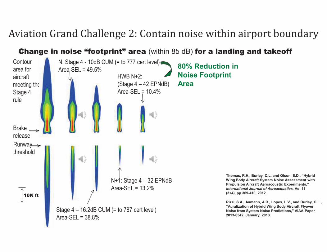
Aviation Grand Challenge 2: Contain noise within airport boundary
CChange in noise “footprint” area (within 85 dB) for a landing and takeoff Contour area for aircraft meeting the Stage 4 rule
N: Stage 4 - 10dB CUM (= to 777 cert level) Area-SEL = 49.5%
N+1: Stage 4 – 32 EPNdB Area-SEL = 13.2%
Runway threshold
Brake release
10K ft
eeeee
t
cert
4 –13.
Stage ea-SEL
(= to
HWB N+2: (Stage 4 – 42 EPNdB) Area-SEL = 10.4%
Stage 4 – 16.2dB CUM (= to 787 cert level) Area-SEL = 38.8%
Thomas, R.H., Burley, C.L, and Olson, E.D., “Hybrid Wing Body Aircraft System Noise Assessment with Propulsion Aircraft Aeroacoustic Experiments,” International Journal of Aeroacoustics, Vol 11 (3+4), pp.369-410, 2012.
Rizzi, S.A., Aumann, A.R., Lopes, L.V., and Burley, C.L., “Auralization of Hybrid Wing Body Aircraft Flyover Noise from System Noise Predictions,” AIAA Paper 2013-0542, January, 2013.
80% Reduction in Noise Footprint Area

N+2 Concepts

N+3 Concepts

NASA N+2 ERA example: hybrid wing body (Nickol, October 2012)
Reference Fuel Burn = 279,800 lbs
“N+1” Composites, High AR WingΔ Fuel Burn = -9.8%
Advanced Stitched CompositesΔ Fuel Burn = -3.4%
Advanced EnginesΔ Fuel Burn = -14.5%
HLFC (Wings, Tails, Nacelles)Δ Fuel Burn = -10.1%
Riblets, ACTE, Δ Fuel Burn = -3.0%
Subsystem Improvements, Δ Fuel Burn = -1.1%
-117,200 lbs(-41.9%)
-41.9% Fuel Burn
Twin Aisle Advanced Conventional Configuration 2020 TRL 6 - 2025 EIS
HWB shape with Sandwich CompositeCenterbody∆ Fuel Burn = -22.7%
-132,500 lbs(-47.3%) Stitched Composite
Centerbody, Outer WingsΔ Fuel Burn = -8.8%
Advanced EnginesΔ Fuel Burn = -10.5%
HLFC on Outer Wings, Nacelles, Δ Fuel Burn = -2.4%
Riblets, ACTE, Δ Fuel Burn = -1.9%Subsystem Improvements, Δ Fuel Burn = -1.1%
Reference Fuel Burn = 279,800 lbs
Hybrid Wing Body (HWB301) Configuration 2020 TRL 6 - 2025 EIS
Subsystem Improvements, � Fuel Burn = -1.1%
Subsystem Improvements, � Fuel Burn = -1.1% Riblets, ACTE, � Fuel Burn = -1.9%
Riblets, ACTE, � Fuel Burn = -3.0% HLFC (Outer Wings, Nacelles), � Fuel Burn = -2.4%
HLFC (Wings, Tails, Nacelles) � Fuel Burn = -2.4%
Advanced Engines � Fuel Burn = -14.5%
Advanced Engines � Fuel Burn = -10.5%
Stitched Composite Centerbody, Outer Wings � Fuel Burn = -8.8%
Advanced Stitched Composites � Fuel Burn = -8.8%
“N+1” Composites, High AR Wing � Fuel Burn = -9.8%
HWB shape with Sandwich Composite Centerbody � Fuel Burn = -22.7%
Reference Fuel Burn = 279,800 lbs Reference Fuel Burn = 279,800 lbs
-117,200 lbs (-41.9%)
-132,500 lbs (-47.3%)
-47.4% Fuel Burn

29 dB, Advanced Technology Conventional (Engine-under-Wing) with BPR 16 UHB(from Berton et al, AIAA 2009-3144)
SOA Conventional with GE-90 like
engines
HWB with GE-90 like engines
Lower noise of baseline HWB from: simple shielding of inlet noise, lower approach speed, absence of flap noise, steeper climb out
Simple shielding of aft fan noise from moving engines 2D upstream on aircraft
Additional noise reduction enabled by PAA technology that reduces both reduces source noise and more effective shielding
Thomas, R.H., Burley, C.L, and Olson, E.D., “Hybrid Wing Body Aircraft System Noise Assessment with Propulsion Aircraft Aeroacoustic Experiments,” International Journal of Aeroacoustics, Vol 11 (3+4), pp.369-410, 2012.

NASA Turboelectric Distributed Propulsion N3X
Large core, low TSFC engines driving superconducting generators Distributed fans ingesting boundary
layer and filling-in center-body wake
Low velocity core exhaust for reduced noise
Electric power from generators distributed to multiple fan motors
Forward and aft fan noise shielded by airframe
Upper surface suction for increased lift coefficient and delayed separation at high AOA
Multiple motor-driven fans with very high effective bypass ratio for reduced fuel burn, noise, and emissions
Reduced induced drag due to wing-tip mounted engine Hyun Dae Kim & Jim Felder

Hybrid Wing Body

Unitized Stitched Composite Structures

Highly Tailored Composite Structures
Tow-Steered CFRP • Fiber winding and automatic tape
placement are industry standards • Fiber tow steering places individual fiber
tows, enabling tighter radii curves and control of fiber distribution • Fiber tow steering equipment exists, but
design and analysis tools to effectively tailor localized laminate properties are lacking • Develop analysis and design tools to
optimize structures through tailored placement of fibers within composite
Fabrication at NCAM/MAF

Weight Reduction and Manufacturing
structural design optimization with curvilinear stiffeners
fabrication & testing of structural designs
lightweight aeroelastically tailored wing structure with integral control surfaces
gddesigns
esigation with
vilinear stiffene
ligh
tailored metallic structures via electron beam free form fabrication (EBF3)
T-stiffened panel designed and optimized using EBF3PanelOpt, in
compression test system
8.30 lb 8.98 lb 9.25 lb 9.89 lb
EBF3PanelOpt Design Candidates Using
Several Variations of Geometry Input Parameters
Virginia Tech, Lockheed Martin,
NASA

Weight Reduction via Advanced
Multifunctional and Tailored Materials
Variable Stiffness Hybrid CNT CFRP/ All CNT
CNT Tapes and Yarns - Nanocomp Technologies
Designer Metallics Functionally Graded Metal Alloys
2 mm
tailored metal alloys vary material properties continuously
throughout a structure nano-structured elements within active polymeric materials for active wing skin
(load bearing + electric conductivity)
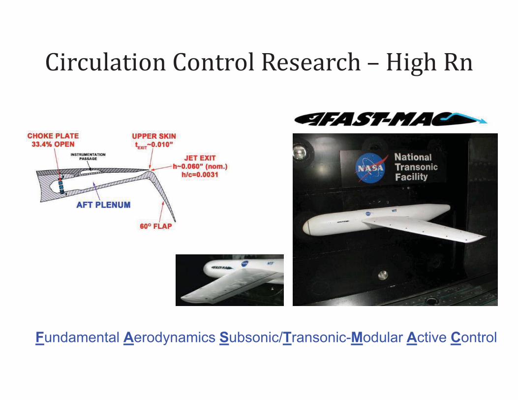
Circulation Control Research – High Rn
Fundamental Aerodynamics Subsonic/Transonic-Modular Active Control

Ultra high BPR engines

DRAG REDUCTION – Via Flow Control
PRSEUS – Pultruded Rod Stitched Efficient Unitized Structure
SFC/NOISE REDUCTION Advanced Cores and Development of Integration of Advanced UHB Engines
WEIGHT REDUCTION

AIRFRAME NOISE High-lift Systems and
Landing Gear
PROPULSION NOISE Fan, Core and Jet Noise
PROPULSION AIRFRAME
AEROACUSTICS Airframe/Propulsion
Interaction & Shielding

CMC COMBUSTOR LINER For higher engine temps
INSTABILITY CONTROL Suppress combustor instabilities
LOW NOX, FUEL FLEXIBLE DESIGN/TEST
Fuel Modulation for high frequency fuel delivery systems
High Temperature SiC electronics circuits and dynamic pressure sensors
Innovative Injector Concept
ASCR Combustion Rig
SIC CMC Concepts
CMC combustor liner

Elastomers – Noise Mitigation & Aero Efficiency
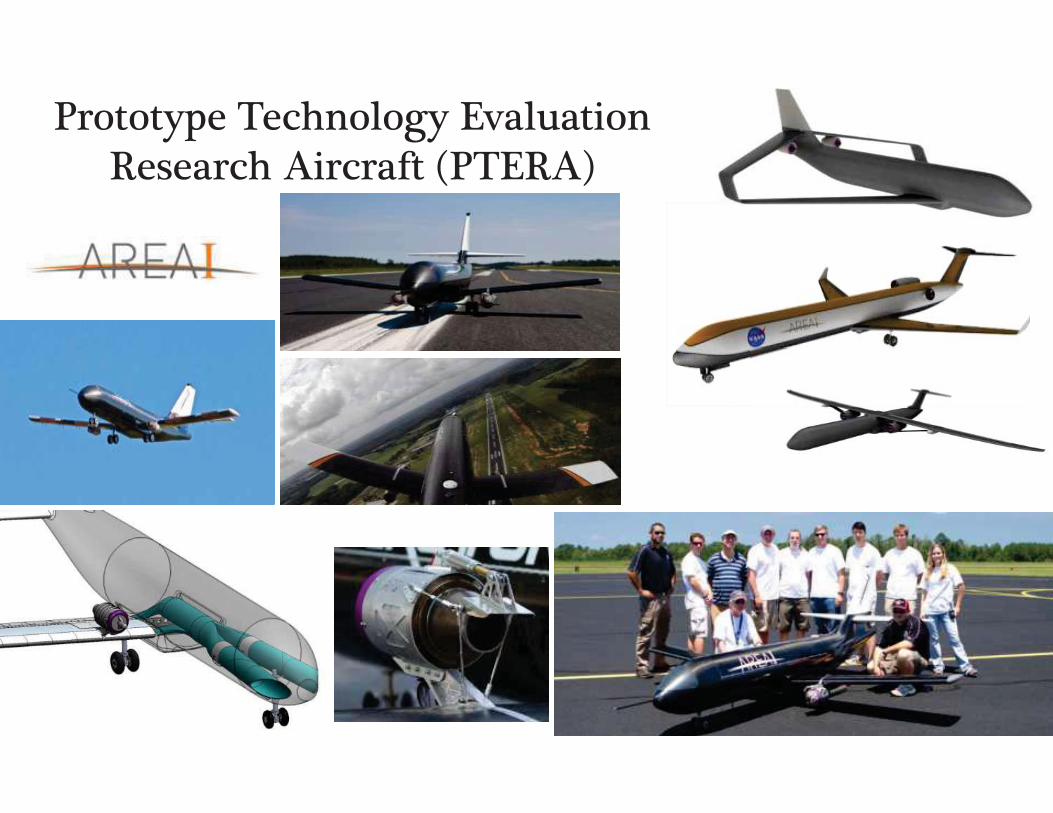
Prototype Technology Evaluation Research Aircraft (PTERA)
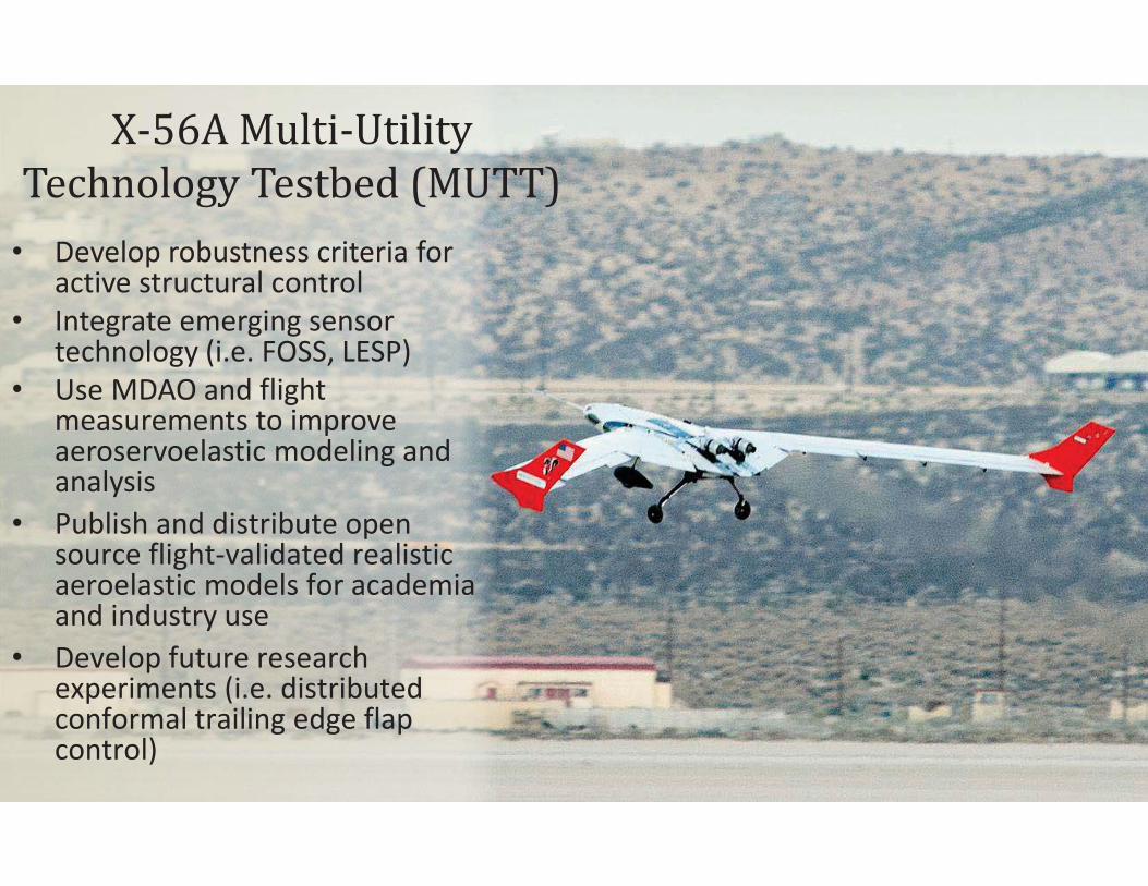
• Develop robustness criteria for active structural control
• Integrate emerging sensor technology (i.e. FOSS, LESP)
• Use MDAO and flight measurements to improve aeroservoelastic modeling and analysis
• Publish and distribute open source flight-validated realistic aeroelastic models for academia and industry use
• Develop future research experiments (i.e. distributed conformal trailing edge flap control)
X-56A Multi-Utility
Technology Testbed (MUTT)

Quiet Supersonic

Downwash
upwash upwash
Formation Flight
upwash
Downwash
upwash

C-17 in Formation Flight
~ 18 wing spans
Not to scale
Approximately to scale
Pahle, et al. “An Initial Flight Investigation of Formation Flight for Drag Reduction on the C-17 Aircraft” AIAA Atmospheric Flight Mechanics Conference, August 2012. AIAA 2012-4802

0 5 10 15 20 25-20
-10
0
10
Sym
met
ric A
ilero
nD
efle
ctio
n (d
eg)
0 5 10 15 20 250
5
10
Trai
ling-
Edg
e Fl
apD
efle
ctio
n (d
eg)
Algorithm Iterations
0 1 2 3 4 5 6 7 8 9 10 11 12 13 14 15 16 17 18 19 20 21 22 23 24 25 26-15
-10
-5
0
5
10
15
20
25
30
Algorithm Iterations
Del
ta F
uel F
low
(per
cent
)
Test 2, 2D, IC:B, M:3, gain:-0.068Test 9, 2D, IC:B, M:3, gain:-0.068Test 14, 2D, IC:B, M:3, gain:-0.068Test 21, 2D, IC:B, M:5, gain:-0.068
Fuel Flow
Ailerons (+TED)
Flaps (+TED)
10~20 minutes
Peak-seeking control: Typical flight results

Effector Position, x (Commanded by Peak-Seeking Controller)
Perf
orm
ance
Mea
sure
men
ts
Performance Function, f(x) (unknown shape)

Effector Position, x (Commanded by Peak-Seeking Controller)
Perf
orm
ance
Mea
sure
men
ts
1 2
3
4 5
6
Initial Excitation
3333333333333
Estimated Gradient
Command (K*gradient)
444444444444444444Command (K*gradient)
5555555
6666666666And so on…

Effector Position, x (Commanded by Peak-Seeking Controller)
Perf
orm
ance
Mea
sure
men
ts
Performance Function, f(x) (unknown shape)
1 2
3
4 5
6 6666666666And so on…

Approach based on work by Ryan and Speyer: Ryan, J.J. and Speyer, J.L., “Peak-Seeking Control Using Gradient and Hessian Estimates”
Proceedings of the 2010 American Control Conference, June 30-July 2, 2010, pp. 611-616. http://hdl.handle.net/2060/20100024511
0
5
10 6 7 8 9 10 11
7.1
7.2
7.3
7.4
7.5
7.6
Symmetric Flaps (deg)
Performance Function Gradient Estimation
Symmetric Aileron (deg)
Fue
l F
low
(Notional)
Vector of control effectors: xk
Pe
rfo
rma
nce
Fu
nct
ion
: f(x
k)
Performance function: fuel flow
Time-Varying Kalman Filter
Persistent
Excitation


Connection to production fuel flow meter
Connection to
Production fuel flow meter New research
fuel flow meter
Inlet Afterburner
Input: from fuel controller
Spare Pickoff (unused)
Research fuel flow meter
Thermocouple

Mode Selection
Surface Positions
Precise Fuel Flow
Stick/Rudder Inputs
Aircraft Sensors
Peak-Seeking Algorithm
Nonlinear Dynamic Inversion
ARTS Output
Alt Hold
Wing Leveler
Speed Hold
+ + Outpuy
Inversion
Alt Hold
++ version
h
��
qc Throttle Command
Symmetric Aileron, TEF, LEF trim positions
Research Fuel Flow Meters
Advanced Research Testbed System (ARTS)


0 200 400 600 800 1000 1200 1400
-5
0
5
10
15
20
25
30
35
40
1 2 3 456 7 8 9 10 111213 1415 16
Time (sec)
Del
ta F
uel F
low
(pe
rcen
t)
2d, IC:C, M:5, gain:-0.068
Raw Sensors20 sec Rolling Average
0 200 400 600 800 1000 1200
-5
0
5
10
15
20
25
30
35
40
1 2 3 4 5 6 7 8 9 1011 12 13141516 1718
Time (sec)
Del
ta F
uel F
low
(pe
rcen
t)
2d, IC:B, M:3, gain:-0.068
Raw Sensors20 sec Rolling Average
0 100 200 300 400 500 600 700 800
-5
0
5
10
15
20
25
30
35
40
1 2 3 4 5 6 7 8 9 10 11 12 13
Time (sec)
Del
ta F
uel F
low
(pe
rcen
t)
2d, IC:D, M:5, gain:-0.101
Raw Sensors20 sec Rolling Average
0 200 400 600 800 1000 1200 1400
-5
0
5
10
15
20
25
30
35
40
123 4 56 7 8 9 10 11 1213 141516171819 20
Time (sec)
Del
ta F
uel F
low
(pe
rcen
t)
3d, IC:F, M:5, gain:-0.068
Raw Sensors20 sec Rolling Average
turn
turn
turn turn

0 1 2 3 4 5 6 7 8 9 10 11 12 13 14 15 16 17 18 19 20 21 22-5
0
5
10
15
20
25
30
35
40
Number of Button Pushes
Del
ta F
uel F
low
(pe
rcen
t)
Algorithm Iterations
2d, IC:C, M:5, gain:-0.0682d, IC:B, M:3, gain:-0.0682d, IC:D, M:5, gain:-0.1013d, IC:F, M:5, gain:-0.068

-20 -15 -10 -5 0 5 10 15 200
2
4
6
8
10
12
14
16
18
20
Symmetric Ailerons (deg)
Trai
ling
Edg
e Fl
aps
(deg
)
Trajectories versus Estimated Performance Function (Flight Data)
-2
-1
0
123456
81012141618202224262830
PF: Fuel Flow (percent)2d, IC:C, M:5, gain:-0.0682d, IC:B, M:3, gain:-0.0682d, IC:D, M:5, gain:-0.1013d, IC:F, M:5, gain:-0.068Approx. Production Trim