
COMMITTEE DRAFT ISO/CD 14692-1 - API...
75
FORM 7 (ISO) Page 1 of 1 Version 2007-04 COMMITTEE DRAFT ISO/CD 14692-1 Date 2013-10-11 Reference number ISO/TC 67 / SC 6 N 1099 Supersedes document WARNING: This document is not an International Standard. It is distributed for review and comment. It is subject to change without notice and may not be referred to as an International Standard. Recipients of this draft are invited to submit, with their comments, notification of any relevant patent rights of which they are aware and to provide supporting documentation. ISO/TC 67 / SC 6 Title Processing equipment and systems Circulated to P- and O-members, and to technical committees and organizations in liaison for: discussion at on [venue/date of meeting] comments by 2014-01-11 [date] approval for registration as a DIS in accordance with 2.5.6 of part 1 of the ISO/IEC Directives, by [date] (P-members vote only: ballot form attached) Secretariat AFNOR P-members of the technical committee or subcommittee concerned have an obligation to vote. English title Petroleum and natural gas industries — Glass-reinforced plastics (GRP) piping — Part 1: Vocabulary, symbols, applications and materials French title Industries du pétrole et du gaz naturel — Canalisations en plastique renforcé de verre (PRV) — Partie 1: Vocabulaire, symboles, applications et matériaux Reference language version: English French Russian Introductory note This project is part of the ISO 14692 series (3rd Edition) developed under ISO/TC 67 SC6 WG5 “Piping systems“ (Convenor : Jorivaldo Medeiros) with Simon Frost as its Project Leader. ISO 14692 series are working under OGP IATF Arrangement, in the frame of Vienna Agreement with CEN/TC 12 (ISO Lead).
Transcript of COMMITTEE DRAFT ISO/CD 14692-1 - API...
FORM 7 (ISO) Page 1 of 1 Version 2007-04
COMMITTEE DRAFT ISO/CD 14692-1
Date
2013-10-11
Reference number
ISO/TC 67 / SC 6 N 1099
Supersedes document
WARNING: This document is not an International Standard. It is distributed for review and comment. It is subject to change
without notice and may not be referred to as an International Standard.
Recipients of this draft are invited to submit, with their comments, notification of any relevant patent rights of which they are aware and to provide supporting documentation.
ISO/TC 67 / SC 6
Title
Processing equipment and
systems
Circulated to P- and O-members, and to technical committees and organizations in liaison for:
discussion at on [venue/date of meeting]
comments by 2014-01-11 [date]
approval for registration as a DIS in accordance with 2.5.6 of
part 1 of the ISO/IEC Directives, by
[date]
(P-members vote only: ballot form attached)
Secretariat AFNOR P-members of the technical committee or subcommittee concerned have an obligation to vote.
English title
Petroleum and natural gas industries — Glass-reinforced plastics (GRP) piping
— Part 1: Vocabulary, symbols, applications and materials
French title
Industries du pétrole et du gaz naturel — Canalisations en plastique renforcé
de verre (PRV) — Partie 1: Vocabulaire, symboles, applications et matériaux
Reference language version: English French Russian
Introductory note
This project is part of the ISO 14692 series (3rd Edition) developed under ISO/TC 67
SC6 WG5 “Piping systems“ (Convenor : Jorivaldo Medeiros) with Simon Frost as its
Project Leader.
ISO 14692 series are working under OGP IATF Arrangement, in the frame of Vienna
Agreement with CEN/TC 12 (ISO Lead).
© ISO 2013 – All rights reserved
Document type: International Standard Document subtype: Document stage: (20) Preparatory Document language: E STD Version 2.5a
ISO/TC 67/SC 6 N Date: 2013-09-23
ISO/WD 14692-1.16
ISO/TC 67/SC 6/WG 5
Secretariat: AFNOR
Petroleum and natural gas industries — Glass-reinforced plastics (GRP) piping — Part 1: Vocabulary, symbols, applications and materials
Industries du pétrole et du gaz naturel — Canalisations en plastique renforcé de verre (PRV) — Partie 1: Vocabulaire, symboles, applications et matériaux
Warning
This document is not an ISO International Standard. It is distributed for review and comment. It is subject to change without notice and may not be referred to as an International Standard.
Recipients of this draft are invited to submit, with their comments, notification of any relevant patent rights of which they are aware and to provide supporting documentation.
ISO/WD 14692-1.16
ii © ISO 2013 – All rights reserved
Copyright notice
This ISO document is a working draft or committee draft and is copyright-protected by ISO. While the reproduction of working drafts or committee drafts in any form for use by participants in the ISO standards development process is permitted without prior permission from ISO, neither this document nor any extract from it may be reproduced, stored or transmitted in any form for any other purpose without prior written permission from ISO.
Requests for permission to reproduce this document for the purpose of selling it should be addressed as shown below or to ISO's member body in the country of the requester:
[Indicate the full address, telephone number, fax number, telex number, and electronic mail address, as appropriate, of the Copyright Manager of the ISO member body responsible for the secretariat of the TC or SC within the framework of which the working document has been prepared.]
Reproduction for sales purposes may be subject to royalty payments or a licensing agreement.
Violators may be prosecuted.
ISO/WD 14692-1.16
© ISO 2013 – All rights reserved iii
Contents Page
Foreword ............................................................................................................................................................ iv
Introduction ......................................................................................................................................................... v
1 Terms, definitions, symbols and abbreviated terms ......................................................................... 1
2 Scope, applications and document structure .................................................................................... 1 2.1 Scope ...................................................................................................................................................... 1 2.2 Applications ........................................................................................................................................... 1 2.3 Document structure .............................................................................................................................. 3
3 Pressure rating ...................................................................................................................................... 3 3.1 MPRxx ...................................................................................................................................................... 3 3.2 Part factors and partial factors ............................................................................................................ 6
4 Classification ......................................................................................................................................... 7 4.1 Joints ...................................................................................................................................................... 7 4.2 Resin matrix ........................................................................................................................................... 8
5 Materials ................................................................................................................................................. 8
6 Dimensions ............................................................................................................................................ 9
Annex A (normative) Terms, definitions, symbols and abbreviated terms ................................................ 11 A.1 General terms ...................................................................................................................................... 11 A.2 Technical terms ................................................................................................................................... 12 A.3 Symbols ................................................................................................................................................ 25 A.4 Abbreviated terms ............................................................................................................................... 29
Annex B (informative) Principle ....................................................................................................................... 31 B.1 General ................................................................................................................................................. 31 B.2 Regression Analysis and Modes of Failure ...................................................................................... 31 B.3 Gradient Choices ................................................................................................................................. 34 B.4 Qualification of prescribed threaded joint ........................................................................................ 35
Annex C (informative) Guidance on Scope Limitations ................................................................................ 36
Annex D (normative) Enquiry Sheet ............................................................................................................... 37
Annex E (normative) Wall Thickness Definitions .......................................................................................... 40
Annex F (informative) Selection of part factor f3,est in the bid process ....................................................... 42
Annex G (informative) Worked example ......................................................................................................... 49
Bibliography ...................................................................................................................................................... 66
ISO/WD 14692-1.16
iv © ISO 2013 – All rights reserved
Foreword
ISO (the International Organization for Standardization) is a worldwide federation of national standards bodies (ISO member bodies). The work of preparing International Standards is normally carried out through ISO technical committees. Each member body interested in a subject for which a technical committee has been established has the right to be represented on that committee. International organizations, governmental and non-governmental, in liaison with ISO, also take part in the work. ISO collaborates closely with the International Electrotechnical Commission (IEC) on all matters of electrotechnical standardization.
International Standards are drafted in accordance with the rules given in the ISO/IEC Directives, Part 2.
The main task of technical committees is to prepare International Standards. Draft International Standards adopted by the technical committees are circulated to the member bodies for voting. Publication as an International Standard requires approval by at least 75 % of the member bodies casting a vote.
Attention is drawn to the possibility that some of the elements of this document may be the subject of patent rights. ISO shall not be held responsible for identifying any or all such patent rights.
ISO 14692-1 was prepared by Technical Committee ISO/TC 67, Materials, equipment and offshore structures for petroleum, petrochemical and natural gas industries, Subcommittee SC 6, Processing equipment and systems.
This second/third/... edition cancels and replaces the first/second/... edition (), [clause(s) / subclause(s) / table(s) / figure(s) / annex(es)] of which [has / have] been technically revised.
ISO 14692 consists of the following parts, under the general title Petroleum and natural gas industries — Glass-reinforced plastics (GRP) piping :
Part 1: Vocabulary, symbols, applications and materials
Part 2: Qualification and manufacture
Part 3: System design
Part 4: Fabrication, installation, inspection and maintenance

ISO/WD 14692-1.16
© ISO 2013 – All rights reserved v
Introduction
The objective of ISO 14692 (all parts) is to provide the oil and gas industry, and the supporting engineering and manufacturing industry, with mutually agreed specifications and recommended practices for the purchase, qualification, manufacturing, design, handling, storage, installation, commissioning and operation of GRP piping systems.
This part, Part 1, provides guidance in the use and interpretation of the other Parts of ISO 14692, namely Parts 2, 3 and 4. Refer to Figure 1. It identifies the 8 basic steps involved:

ISO/WD 14692-1.16
vi © ISO 2013 – All rights reserved
Figure 1 — Guidance on the use of ISO 14692 (all parts)

ISO/WD 14692-1.16
© ISO 2013 – All rights reserved vii
Step 1: The Bid Process. Here, the principal completes an enquiry sheet (refer to Annex D) that defines the design pressures and temperatures of the piping system as well as the application, required pipe sizes and required components (bends, tees, reducers, flanges, etc.). The principal also verifies that the scope of the application is within the limits of ISO 14692 (refer to Annex C). The principal and manufacturer shall also come to an agreement on the value of the estimated value of the part factor f3,est (refer to Annex F).
In some cases, the manufacturer may wish to offer a product that meets or exceeds the requirements in the Enquiry sheet that has already been manufactured, qualified and inspected per ISO 14692-2.In this case, steps 2 thru 4 would not need to be repeated.
Step 2: Manufacturer's Data. Recognizing that long term regression testing can easily take 2 or more years to complete, the manufacturer will most likely have already selected target values for MPRxx, the long term envelope(s) and the minimum reinforced wall thicknesses. The manufacturer shall determine the appropriate gradient and rd1 000,xx can then be calculated to suit the survival test duration. Additional basic data such as pipe sizes, wall thicknesses, SIFs, production processes and jointing instructions shall also be provided.
Step 3: Qualification Process. Here, the manufacturer conducts survival tests to qualify the pressure and temperature. If applicable, the manufacturer shall also qualify fire performance and electrical conductivity properties. Elastic properties, potable water certification, impact and low temperature performance are also addressed in this step. Just as with Step 2, the manufacturer may have already completed part or all of the qualification process prior to Step 1, the bid process.
Step 4: Quality Programme. Step 4 defines the basic requirements for the manufacturer's quality management system.
Step 5: Generate Envelopes. Step 5 is the first major step in Part 3. Here, partial factors and part factors are identified and combinations of these factors are determined. Formulae are then provided to calculate the design envelope(s).
Step 6: Stress Analysis. Step 6 identifies the flexibility factors and SIFs to be used in the stress analysis. It also defines the allowable values for vertical deflection, stresses and buckling. An analytical formula for external pressure is provided.
Step 7: Bonder Qualification. Step 7 is the first major step in Part 4 where the bonder qualification process is defined.
Step 8: Installation, Field Hydrotest. Step 8 is the last major step where installation issues are addressed.

WORKING DRAFT ISO/WD 14692-1.16
© ISO 2013 – All rights reserved 1
Petroleum and natural gas industries — Glass-reinforced plastics (GRP) piping — Part 1: Vocabulary, symbols, applications and materials
1 Terms, definitions, symbols and abbreviated terms
For terms, definitions, symbols and abbreviated terms, refer to Annex A.
2 Scope, applications and document structure
2.1 Scope
This part, Part 1 of ISO 14692, defines the applications, pressure rating methodology, the classification of the products according to application, type of joint and resin matrix and the limitations to both the materials of construction and the dimensions. It also lists the terms, definitions and symbols used and provides guidance in the use and interpretation of the other Parts of ISO 14692, namely Parts 2, 3 and 4.
ISO 14692 (all parts) is applicable to GRP piping systems that 1) utilize joints that are capable of restraining axial thrust from internal pressure, temperature change and fluid hydrodynamic forces and 2) have a trapezoidal shape for its design envelope. It is primarily intended for offshore applications on both fixed and floating topsides facilities, but it may also be used for the specification, manufacture, testing and installation of GRP piping systems in other similar applications found onshore, e.g. produced-water, firewater systems and general industrial use.
2.2 Applications
ISO 14692 (all parts) applies to the specification, manufacture, testing and installation of GRP piping and pipeline systems associated with oil and gas industry production, processing and utility service applications. It is intended for offshore applications on both fixed and floating topsides facilities, but it may also be used as guidance for GRP piping and pipeline systems in oil and gas industry applications found onshore.
For floating installations, reference should be made to the design, construction and certification standards for the hull or vessel, since these may allow alternative codes and standards for GRP piping associated with marine and/or ballast systems. However, it is recommended that ISO 14692 (all parts) be used for such applications to the maximum degree attainable.
ISO 14692 (all parts) may also be used as the general basis for specification of pipe used for pump caissons, stilling tubes, I-tubes, seawater lift risers and other similar items.
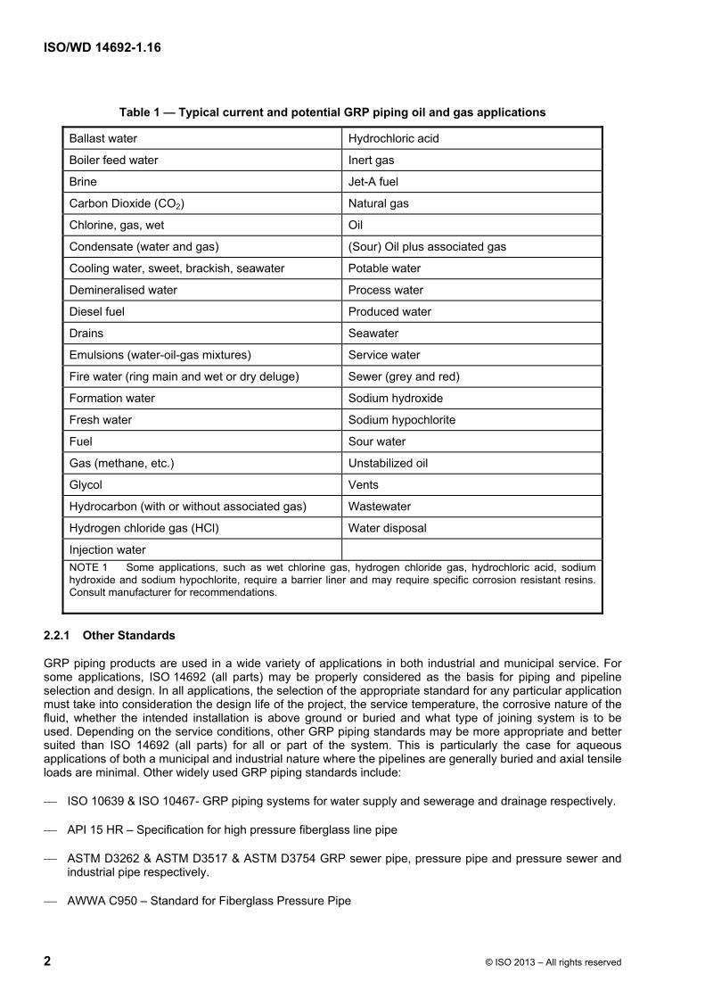
Typical oil and gas industry applications for the use of GRP pipe include those listed in Table 1.
ISO/WD 14692-1.16
2 © ISO 2013 – All rights reserved
Table 1 — Typical current and potential GRP piping oil and gas applications
Ballast water Hydrochloric acid
Boiler feed water Inert gas
Brine Jet-A fuel
Carbon Dioxide (CO2) Natural gas
Chlorine, gas, wet Oil
Condensate (water and gas) (Sour) Oil plus associated gas
Cooling water, sweet, brackish, seawater Potable water
Demineralised water Process water
Diesel fuel Produced water
Drains Seawater
Emulsions (water-oil-gas mixtures) Service water
Fire water (ring main and wet or dry deluge) Sewer (grey and red)
Formation water Sodium hydroxide
Fresh water Sodium hypochlorite
Fuel Sour water
Gas (methane, etc.) Unstabilized oil
Glycol Vents
Hydrocarbon (with or without associated gas) Wastewater
Hydrogen chloride gas (HCl) Water disposal
Injection water
NOTE 1 Some applications, such as wet chlorine gas, hydrogen chloride gas, hydrochloric acid, sodium hydroxide and sodium hypochlorite, require a barrier liner and may require specific corrosion resistant resins. Consult manufacturer for recommendations.
2.2.1 Other Standards
GRP piping products are used in a wide variety of applications in both industrial and municipal service. For some applications, ISO 14692 (all parts) may be properly considered as the basis for piping and pipeline selection and design. In all applications, the selection of the appropriate standard for any particular application must take into consideration the design life of the project, the service temperature, the corrosive nature of the fluid, whether the intended installation is above ground or buried and what type of joining system is to be used. Depending on the service conditions, other GRP piping standards may be more appropriate and better suited than ISO 14692 (all parts) for all or part of the system. This is particularly the case for aqueous applications of both a municipal and industrial nature where the pipelines are generally buried and axial tensile loads are minimal. Other widely used GRP piping standards include:
ISO 10639 & ISO 10467- GRP piping systems for water supply and sewerage and drainage respectively.
API 15 HR – Specification for high pressure fiberglass line pipe
ASTM D3262 & ASTM D3517 & ASTM D3754 GRP sewer pipe, pressure pipe and pressure sewer and industrial pipe respectively.
AWWA C950 – Standard for Fiberglass Pressure Pipe
ISO/WD 14692-1.16
© ISO 2013 – All rights reserved 3
EN 1796 & EN 14364 – GRP piping systems for water supply and sewerage and drainage respectively.
ISO 14692 is not intended to be applied to sewerage and drainage applications though it may provide useful guidance in specific areas not addressed in alternative standards. ISO 14692 is also not specifically intended for non-structural applications such as open drain systems and other low pressure piping applications.
ISO 14692 (all parts) covers all the main components that form part of a GRP pipeline and piping system (pipe, bends, reducers, tees, supports, flanged joints) with the exception of valves and instrumentation.
2.3 Document structure
ISO 14692-2, ISO 14692-3 and ISO 14692-4 follow the individual phases in the life cycle of a GRP piping system, i.e. from qualification and manufacture through design to fabrication, installation, operation and decommissioning.
Each part is therefore aimed at the relevant parties involved in that particular phase.
Part 1: Vocabulary, symbols, applications and materials. It provides guidance in the use of the other 3 parts of ISO 14692, namely Parts 2, 3 and 4. It defines the applications, pressure rating methodology, the classification of the products according to application, type of joint and resin matrix and the limitations to both the materials of construction and the dimensions. It also lists the terms, definitions and symbols used. Main users are envisaged to include all parties in the life cycle of a typical GRP piping system. ISO 14692-1 should be used in conjunction with the part of specific relevance.
Part 2: Qualification and manufacture. Its objective is to enable the supply of GRP components with known and consistent properties from any source. Main users of the document are envisaged to be the principal, the manufacturer, certifying authorities and government agencies.
Part 3: System design. Its objective is to ensure that piping systems, when designed using the components qualified in ISO 14692-2, meet the specified performance requirements. Main users of the document are envisaged to be the principal, the manufacturer, design contractors, certifying authorities and government agencies.
Part 4: Fabrication, installation, inspection and maintenance. Its objective is to ensure that installed piping systems meet the specified performance requirements throughout their service life. Main users of the document are envisaged to be the principal, the manufacturer, fabrication/installation contractors, repair and maintenance contractors, certifying authorities and government agencies.
3 Pressure rating
3.1 MPRxx
MPRxx is the maximum pressure rating at sustained conditions for a 20 year design life at the temperature of xx °C. MPRxx shall be the maximum catalogue value published by the manufacturer. MPRxx shall be defined at 65 °C for GRE (MPR65) and 21 °C for GRUP and GRVE (MPR21). The manufacturer shall also publish MPRxx at other temperatures. Refer to Clause 3.3 of Part 2.
ISO/WD 14692-1.16
4 © ISO 2013 – All rights reserved
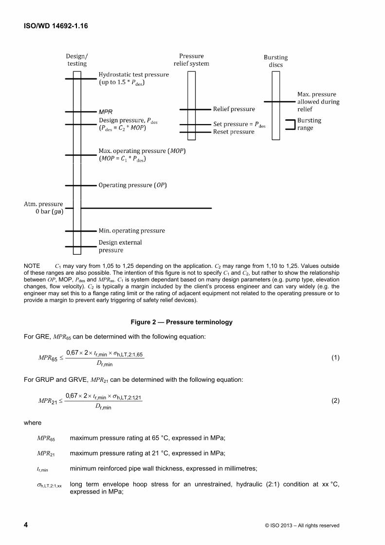
NOTE C1 may vary from 1,05 to 1,25 depending on the application. C2 may range from 1,10 to 1,25. Values outside of these ranges are also possible. The intention of this figure is not to specify C1 and C2, but rather to show the relationship between OP, MOP, Pdes and MPRxx. C1 is system dependant based on many design parameters (e.g. pump type, elevation changes, flow velocity). C2 is typically a margin included by the client’s process engineer and can vary widely (e.g. the engineer may set this to a flange rating limit or the rating of adjacent equipment not related to the operating pressure or to provide a margin to prevent early triggering of safety relief devices).
Figure 2 — Pressure terminology
For GRE, MPR65 can be determined with the following equation:
minr,
1,65:LT,2h,minr,65
2670
D
σt,MPR
(1)
For GRUP and GRVE, MPR21 can be determined with the following equation:
minr,
21,1:2,LTh,minr,21
267,0
D
tMPR
(2)
where
MPR65 maximum pressure rating at 65 °C, expressed in MPa;
MPR21 maximum pressure rating at 21 °C, expressed in MPa;
tr,min minimum reinforced pipe wall thickness, expressed in millimetres;
h,LT,2:1,xx long term envelope hoop stress for an unrestrained, hydraulic (2:1) condition at xx °C, expressed in MPa;
ISO/WD 14692-1.16
© ISO 2013 – All rights reserved 5
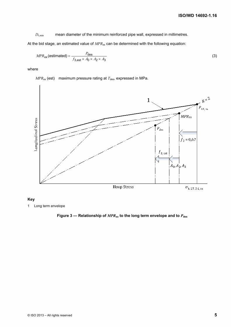
Dr,min mean diameter of the minimum reinforced pipe wall, expressed in millimetres.
At the bid stage, an estimated value of MPRxx can be determined with the following equation:
320est3,
desxx )(estimated
AAAf
PMPR
(3)
where
MPRxx (est) maximum pressure rating at Tdes, expressed in MPa.
Key
1 Long term envelope
Figure 3 — Relationship of MPRxx to the long term envelope and to Pdes
ISO/WD 14692-1.16
6 © ISO 2013 – All rights reserved
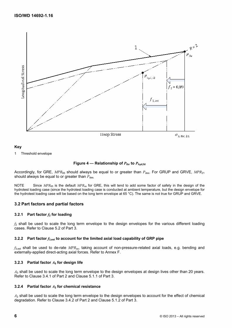
Key
1 Threshold envelope
Figure 4 — Relationship of Pthr to Phyd,fd
Accordingly, for GRE, MPR65 should always be equal to or greater than Pdes. For GRUP and GRVE, MPR21 should always be equal to or greater than Pdes.
NOTE Since MPR65 is the default MPRxx for GRE, this will tend to add some factor of safety in the design of the hydrotest loading case (since the hydrotest loading case is conducted at ambient temperature, but the design envelope for the hydrotest loading case will be based on the long term envelope at 65 °C). The same is not true for GRUP and GRVE.
3.2 Part factors and partial factors
3.2.1 Part factor f2 for loading
f2 shall be used to scale the long term envelope to the design envelopes for the various different loading cases. Refer to Clause 5.2 of Part 3.
3.2.2 Part factor f3,est to account for the limited axial load capability of GRP pipe
f3,est shall be used to de-rate MPRxx, taking account of non-pressure-related axial loads, e.g. bending and externally-applied direct-acting axial forces. Refer to Annex F.
3.2.3 Partial factor A0 for design life
A0 shall be used to scale the long term envelope to the design envelopes at design lives other than 20 years. Refer to Clause 3.4.1 of Part 2 and Clause 5.1.1 of Part 3.
3.2.4 Partial factor A2 for chemical resistance
A2 shall be used to scale the long term envelope to the design envelopes to account for the effect of chemical degradation. Refer to Clause 3.4.2 of Part 2 and Clause 5.1.2 of Part 3.
ISO/WD 14692-1.16
© ISO 2013 – All rights reserved 7
3.2.5 Partial factor A3 for cyclic loading
A3 shall be used to scale the long term envelope to the design envelopes to account for the effects of cyclic loading. Refer to Clause 3.4.3 of Part 2 and Clause 5.1.3 and Annex B of Part 3.
4 Classification
4.1 Joints
4.1.1 Unrestrained Joints
ISO 14692 applies only to those piping systems utilizing joints that can take axial loads, i.e. restrained joints or bi-axially loaded joints. Examples of restrained joints include, but are not limited to, adhesive-bonded joints, laminated joints and prescribed threaded joints.
Unrestrained joints, such as the o-ring bell-and-spigot (without locking strip), are not covered by this standard.
NOTE Restrained joints apply significant axial stress from thrust and therefore must incorporate the concept embodied in the trapezoidal design envelope to be properly specified and analyzed.
4.1.2 Classification of joints
Joints shall be classified as either:
a) prescribed threaded joints;
b) restrained joints other than prescribed threaded joints.
This classification has an effect on the following topics (refer to Table 2):
a) the selection process for the gradient, based on either measured or default gradients, (see 4.1.2.1 and 4.1.2.2);
b) the test pressure for training (Part 4, Annex C);
c) mill hydrostatic testing (Part 2, 6.2.2).
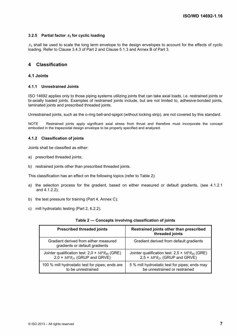
Table 2 — Concepts involving classification of joints
Prescribed threaded joints Restrained joints other than prescribed threaded joints
Gradient derived from either measured gradients or default gradients
Gradient derived from default gradients
Jointer qualification test: 2,0 × MPR65 (GRE) 2,0 × MPR21 (GRUP and GRVE)
Jointer qualification test: 2,5 × MPR65 (GRE) 2,5 × MPR21 (GRUP and GRVE)
100 % mill hydrostatic test for pipes; ends are to be unrestrained
5 % mill hydrostatic test for pipes; ends may be unrestrained or restrained

ISO/WD 14692-1.16
8 © ISO 2013 – All rights reserved
4.1.2.1 Prescribed threaded joints
Recognizing that the gradient of plain pipe may not be representative of prescribed threaded joints, piping systems that utilize prescribed threaded joints (i.e. mechanical joints that meet the requirements of API 15HR) shall be designed using a gradient derived from either 1) measured gradients or 2) default gradients for regression based on industry wide experience. The minimum gradient shall be 0,030 irrespective of the measured gradient.
NOTE Gradients are specified as positive numbers even though the slope of the regression line is negative.
4.1.2.2 Restrained joints other than prescribed threaded joints
Recognizing that the regression analysis from long-term testing, such as ASTM D2992, provides an indication of performance, not an exact, repeatable measure, piping systems utilizing restrained joints other than the prescribed threaded joints shall be designed using a gradient derived from default gradients for regression based on industry wide experience.
While default gradients are used in the selection process, the manufacturer shall still be required to provide a single regression curve data set per Clause 3.1 of Part 1. The manufacturer's gradient shall be compared to the default gradient (see Annex B of ISO 14692-2).
4.2 Resin matrix
The resin matrix for the products shall be classified as:
a) GRE;
b) GRUP;
c) GRVE;
d) other resin system.
This classification has an effect on the following topics (refer to Table 3):
a) the default temperature (65 °C for GRE and 21 °C for GRUP and GRVE);
b) the default gradient (see Part 2 Annex B).
Table 3 — Concepts involving resin system
GRE GRVE GRUP
Default temperature = 65 °C Default temperature = 21 °C Default temperature = 21 °C
5 Materials
Application of ISO 14692 (all parts) shall be limited to the manufacture of rigid components made from fibre-reinforced thermosetting resins. Typical resins are epoxy, polyester, vinyl ester and phenolic. Thermoplastic resins are excluded.
NOTE The resins as listed are generic compounds. Their performance and properties of thermal, mechanical and chemical resistance vary significantly depending on the resin and curing agent used to cure them. The user is cautioned to ascertain that the resin and curing agent are known for the resin system planned to be used.
ISO/WD 14692-1.16
© ISO 2013 – All rights reserved 9
The principal reinforcement material of the component wall shall be glass fibre, e.g. continuous and/or woven rovings. Other types of fibre reinforcement, such as carbon or aramid fibre, may be used to provide local strengthening within joints and fittings. Use of low electrical resistivity fibres, e.g. carbon, for non-structural purposes to provide electrical conductivity shall be permitted.
ISO 14692 (all parts) is not applicable to pipe systems that incorporate internal thermoplastic or elastomeric liners. This is because such materials may introduce significant changes in performance characteristics of the GRP piping.
NOTE The use of a thermoplastic liner will result in change of the failure mode for pressure retention.
The maximum allowable temperature is determined by the resin type and state of cure.
The minimum recommended temperature for GRP regardless of the resin system is – 35 °C, although lower temperatures may be considered.
NOTE GRP materials do not undergo ductile/brittle transition at temperatures as low as –35 °C, hence, there is no significant abrupt change in mechanical properties at low temperatures. A concern is that at temperatures lower than 35 °C, internal residual stresses could become large enough to reduce the safe operating envelope of the piping system. While there is some recent test data at temperatures as low as –65 °C, this data has not been considered in the writing of this document.
ISO 14692 (all parts) is not applicable to pipe systems that incorporate fillers or aggregates except when the additive or filler material is used as a liner on the inside of the pipe to provide enhanced performance, e.g. wear resistance and electrical conductivity. The liner material shall be compatible with the service conditions.
External coatings may be used to provide thermal insulation, fire resistance, UV protection and/or electrical conductivity. Consideration shall be given to identifying how such coatings affect, if at all, the ability to detect possible leakage paths through the wall of the component during hydrotesting, or the effect that the additional mass of external coating may have on the overall stress analysis.
6 Dimensions
For guidance purposes, the typical pressure-diameter range of pipes covered by ISO 14692 (all parts) is indicated by Figure 5, which represents a compromise between the current application experience envelope of GRP pipelines and piping systems and commercial availability.
The curve in Figure 5 can be approximated by
DN × MPRxx = 3 000
where
DN Nominal diameter, expressed in millimetres
MPRxx Maximum pressure rating at xx °C, expressed in MPa
In Figure 5, MPRxx is a maximum of 27,5 and DN is a maximum of 4 000.
There are no restrictions on the thickness to diameter ratios used in the structural calculations given in ISO 14692 (all parts).
NOTE Axial stress calculations in Part 3 are based on thick-wall equations. The use of Dr,min in the hoop stress calculations produces a value very close to thick wall hoop stresses.
ISO 14692 (all parts) covers all the main components that form part of a GRP pipeline and piping system (pipe, bends, reducers, tees, supports, flanged joints) with the exception of valves and instrumentation.

ISO/WD 14692-1.16
10 © ISO 2013 – All rights reserved
Figure 5 — Envelope of pressure/diameter range of GRP pipes and piping systems based on current experience
ISO/WD 14692-1.16
© ISO 2013 – All rights reserved 11
Annex A (normative)
Terms, definitions, symbols and abbreviated terms
Terms and Definitions
For the purposes of this document, the following terms and definitions apply.
A.1 General terms
A.1.1 authority having jurisdiction third-party organization required to be satisfied with the standard of engineering proficiency and safety of a project
EXAMPLE A classification society, verification body or government regulatory body.
A.1.2 contractor party which carries out all or part of the design, engineering, procurement, construction and commissioning for a project or operation of a facility
NOTE The principal (A.1.9) may undertake all or part of the duties of the contractor.
A.1.3 designer party which carries out all or part of the design for a project or facility
A.1.4 installer party which carries out all or part of the construction and commissioning of composite pipe installations and installation work for a project
A.1.5 installation inspector person able to perform satisfactory and independent inspection of composite pipe installations and installation work
A.1.6 installation supervisor tradesman able to perform practical supervision of the installation and joining of composite pipes
A.1.7 manufacturer party which manufactures or supplies composite pipe and piping components to perform the duties specified by the contractor
A.1.8 operator party which assumes ultimate responsibility for the operation and maintenance of the piping system
NOTE The operator may or may not be the same as the principal or principal's agent.

ISO/WD 14692-1.16
12 © ISO 2013 – All rights reserved
A.1.9 principal party that initiates the project and ultimately pays for its design and construction
NOTE The principal generally specifies the technical requirements and is ultimately responsible for ensuring that safety and all other issues are addressed. The principal may also include an agent or consultant, authorized to act for the principal.
A.1.10 site location where piping system is installed
A.2 Technical terms
A.2.1 accelerator substance which, when mixed with a catalyst or a resin, will speed up the chemical reaction between catalyst and resin
NOTE The misuse of a cobalt mixture directly with a peroxide (e.g MEKP -catalyst) might cause an explosion or fire.
A.2.2 active fire protection method of extinguishing fire by application of substances such as halon, water, CO2, foam, etc.
A2.3 adhesive joint adhesive bond glued joint socket joint rigid type of joint between two components made using an adhesive
NOTE Generally consists of a slightly conical (tapered) bell end and a machined (cylindrical or tapered) spigot end.
A.2.4 anisotropic exhibiting different properties when tested along axes in different directions
A.2.5 carbon fibre fibre produced by the pyrolysis of organic precursor fibres, such as rayon, polyacrylonitrile, in an inert environment
A.2.6 cavitation formation of pockets of vapour in a liquid that suddenly collapse, causing very high localized pressures which can lead to serious erosion of boundary surfaces
A.2.7 chemical-resistant glass ECR glass Boron-free glass glass fibre or synthetic veil having a specific chemical resistance against acids
NOTE Such glass may be used as a reinforcement for the resin-rich internal liner of GRP pipe or as a reinforcement in the structural portion of GRP pipe.
ISO/WD 14692-1.16
© ISO 2013 – All rights reserved 13
A.2.8 collapse pressure external pressure differential which causes buckling collapse of a component
A.2.9 chopped roving Strands of glass fibre cut to a desired length from rovings
A.2.10 chopped strand mat CSM reinforcement structure in which short lengths of glass fibre tows, held together by an emulsion or powder binding agent, are dispersed in random directions within a single plane
NOTE Chopped strand mat should not be confused with chopped roving. The latter may not be in mat form and may be loose rovings from a chopper gun.
A.2.11 cure change irreversibly the properties of a thermosetting resin by chemical reaction
NOTE 1 Examples of such chemical reaction are condensation, ring closure and addition.
NOTE 2 Cure may be accomplished by the addition of a curing agent, with or without heat and pressure.
A.2.12 cure cycle polymerization time/temperature/pressure cycle used to cure a thermosetting resin system from a liquid to a solid
A.2.13 curing agent catalytic or reactive agent that, when added to a resin, causes polymerization
NOTE Also called hardener (A.2.51), for epoxies.
A.2.14 delamination separation of two adjacent plies or layers of material in a laminate resulting from lack of adhesion
NOTE May occur either locally or covering a wide area.
A.2.15 design envelope long term envelope reduced by the part factor f2 and the partial factors A0, A2 and A3
A.2.16 design external pressure maximum positive external pressure differential, i.e. external minus internal pressure, intended to be experienced by a component during its service life
ISO/WD 14692-1.16
14 © ISO 2013 – All rights reserved
A.2.17 design pressure Pdes purchaser nominated maximum pressure to which a piping system must be designed to operate at the nominated design temperature (Tdes) and for the nominated design life (Ldes)
NOTE Pdes is typically considered as a sustained pressure though an additional Pdes occasional may also be nominated. Pdes should be selected based on the maximum operating pressure plus a purchaser selected uplift i) to accommodate pressure uncertainty, ii) to avoid triggering of pressure safety devices, iii) to match the rating of attached piping or equipment and iv) to provide a design margin for other purposes.
A.2.18 design temperature Tdes for each design condition, maximum fluid temperature that can be reached during service
A.2.19 differential scanning calorimetry DSC method for determining the glass transition temperature of a polymer
A.2.20 dynamic mechanical thermal analysis DMTA method for determining the glass transition temperature of a polymer or GRP (A.2.44) component
A.2.21 earth, verb, GB ground, verb, US provide electrical contact with earth
A.2.22 E-glass glass fibre normally used to reinforce GRP (A.2.44) pipes, consisting mainly of SiO2, Al2O3 and MgO
A.2.23 elastomeric bell-and-spigot seal lock joint rubber seal lock joint rubber sealed key lock joint joint connection made up of a spigot end and a socket end with “O” or lip-sealing rings and some axial restraining device capable of resisting the full thrust from internal pressure
A.2.24 electrically conductive conductive having a volume resistivity equal to or lower than 104 m
A.2.25 environmental stress cracking ESC formation of cracks in a polymer or composite caused by exposure to a chemical or environment under stress

ISO/WD 14692-1.16
© ISO 2013 – All rights reserved 15
A.2.26 epoxide epoxy compound containing at least two epoxy or oxirane rings
NOTE 1 Chemically, an epoxy ring is a three-membered ring containing two carbon atoms and one oxygen atom.
NOTE 2 The most widely used epoxy resin is termed DGEBA (diglycidyl ether of bisphenol A). Epoxy resins are always used in conjunction with curing agents or hardeners, i.e. substances that react with the epoxy rings, producing hydroxyl groups and other products, and linking the originally linear molecules into a rigid three-dimensional network.
A.2.27 extrados the exterior curve of an elbow or torus
cf. intrados (A.2.60)
A.2.28 failure loss of structural integrity and/or transmission of fluid leakage through the wall of a component or a joint
A.2.29 fibre filamentary material with a finite length that is at least 100 times its diameter and prepared by drawing from a molten bath, spinning or deposition on a substrate
NOTE Filaments are usually of extreme length and very small diameter, usually less than 25 µm. Normally, filaments are assembled as twisted (yarn) or untwisted (tow) bundles comprising hundreds or thousands of filaments.
A.2.30 filament winding process for fabricating a composite structure in which continuous reinforcements, e.g. fibre tows, are either previously impregnated with a matrix material or impregnated during the winding
A.2.31 fire classification code code designation of the fire performance of pipe component in terms of fire endurance and fire reaction properties
A.2.32 fire endurance fire resistance ability to maintain functional performance in a fire
A.2.33 fire-reaction property material property which contributes to spread of fire, heat release and smoke/toxic emissions
A.2.34 fitter jointer pipe bonder tradesman able to perform satisfactory and independent work in the installation and joining of composite pipes
A.2.35 fitting pressure-tight fluid-containing components with a geometry different from straight pipe
EXAMPLES Flanges, tees, elbows, reducers and fabricated branch.
ISO/WD 14692-1.16
16 © ISO 2013 – All rights reserved
A.2.36 flame retardant chemical that is used to reduce or eliminate the tendency of a resin to burn
A.2.37 flange joint mechanical joint with face flanges for which the bolt circle and face dimensions conform to a recognized standard
A.2.38 flexibility factor ratio of the flexibility in bending of a component/fitting to that of the flexibility of a straight pipe of the same lamination, Young's modulus and thickness having a length corresponding to the developed length of the fitting
A.2.39 free-end testing pressure-testing arrangement using pipe end closures of a type such that internal pressure produces axial, as well as hoop and radial, stresses in the component wall
cf. restrained-end testing (A.2.107)
A.2.40 function ability of the piping system to perform its primary purpose, i.e. to deliver a minimum quantity of fluid at a specified minimum pressure
A.2.41 furnace test test in a compartment furnace where the time-temperature curve to be followed is to a defined standard
A.2.42 gel coat quick-setting resin applied either 1) to the surface of a mould and gelled before lay-up or 2) to the exterior of a laminate as part of the external corrosion barrier
NOTE The gel coat becomes an integral part of the finished laminate, and is usually used to provide specific service characteristics (see liner, A.2.69).
A.2.43 glass-fibre-reinforced epoxy GRE epoxy resin-based composite that is reinforced with glass fibre
A.2.44 glass-fibre-reinforced plastic GRP fibreglass composite reinforced plastic reinforced thermosetting resin plastic RTR plastic polymeric resin-based composite that is reinforced with glass fibre
NOTE 1 The predominant glass fibre is E-glass (A.2.22).
NOTE 2 ISO 14692 (all parts) is restricted to the use of thermosetting resins (A.2.116).
NOTE GRE, GRUP and GRVE are types of GRP.

ISO/WD 14692-1.16
© ISO 2013 – All rights reserved 17
A.2.45 glass-fibre-reinforced unsaturated polyster GRUP unsaturated polyester resin-based composite that is reinforced with glass fibre
A.2.46 glass-fibre-reinforced vinyl ester GRVE epoxy vinyl ester resin-based composite that is reinforced with glass fibre
A.2.47 glass transition temperature Tg
temperature at which amorphous polymer undergoes a marked change in properties on passing from the rubbery to glassy state
NOTE This observed change in properties is associated with the virtual cessation of local molecular motion in the polymer. Below their glass-transition temperature, amorphous polymers have many of the properties associated with ordinary inorganic glasses, whilst above this temperature the polymers possess rubbery characteristics.
A.2.48 gradient slope slope of internal pressure over time, on a logarithmic-logarithmic scale, of a static regression curve
NOTE The slope, although negative, is published and used as a positive number.
A.2.49 grounding clamp metal fitting attached to the pipe component to provide an electrical connection to earth
A.2.50 hand lay-up process for fabricating a composite structure in which discontinuous reinforcements, e.g. woven mats, chopped strand mats, are impregnated with a matrix material and are manually applied on a mandrel
A.2.51 hardener substance or mixture added to a plastic composition to promote or control the curing action by taking part in it
NOTE Also called curing agent (A.2.13), for epoxies.
A.2.52 hazardous area three-dimensional space in which a combustible or explolsive atmosphere may be expected to be present frequently enough to require special precautions for the control of potential ignition sources
NOTE Hazardous areas are typically defined by local, national or international standards such as the National Electric Code (NEC) in the United States.
A.2.53 heat-distortion temperature HDT temperature at which a standard test bar deflects a specified amount under a stated load

ISO/WD 14692-1.16
18 © ISO 2013 – All rights reserved
A.2.54 heat flux density of heat flow rate quantity of heat divided by area and time
A.2.55 hydrocarbon pool fire fire caused by ignition of a pool of hydrocarbon liquid
A.2.56 hydrotest pressure test to verify the pressure-retention integrity of a piping system after installation
cf. mill hydrostatic test (A.2.78)
NOTE Also used as a leak test.
A.2.57 impregnate saturate the reinforcement with a resin
A.2.58 incendive discharge electrostatic spark discharge of sufficient energy to ignite a flammable atmosphere
A.2.59 integrity minimum structural capability required to enable the pipe system to fulfil its function
A.2.60 intrados the interior curve of an elbow or torus
A.2.61 intumescent passive fire-protection coating which, in the presence of fire, expands to create an inert insulating “char” layer
A.2.62 jet fire turbulent diffusion flame resulting from the combustion of a fuel continuously released with significant momentum in a particular direction
A.2.63 joint means of connecting two or more components
EXAMPLE Plain pipe to a fitting, or plain pipe to plain pipe.
A.2.64 laminae thin sheets of reinforcing fibres in a resin matrix built up into a flat or curved arrangement
A.2.65 laminate, verb unite laminae with a bonding material, usually using pressure and heat
NOTE Normally used with reference to flat sheets, but can also refer to tubes. A product made by such bonding is referred to as a laminate.
ISO/WD 14692-1.16
© ISO 2013 – All rights reserved 19
A.2.66 laminated joint butt-and-wrap joint butt-and-strap joint butt-welded joint joint consisting of plain-ended pipe and fittings laminated together with reinforcing fibres and resin/hardener mixture
A.2.67 laying length actual length of a line, corresponding to the initial length plus the increase afforded by the fitting or integral joint when installed
A.2.68 leak test pressure test to determine the presence of leaks at joints or within components of a pipe system
NOTE Usually carried out at a pressure lower than the hydrotest and for a longer period.
A.2.69 liner continuous resin-rich coating on the inside surface of a pipe or fitting component, used to protect the laminate from chemical attack or to prevent leakage under stress
NOTE The liner may also be used to provide enhanced abrasion and erosion resistance.
A.2.70 long term envelope envelope that defines the stress levels that are just below that which can potentially cause irreversible damage during continuous or occasional loading conditions at a specified temperature
A.2.71 lower confidence limit LCL 97,5 % lower confidence limit of the nominal long-term regression line for hydrostatic pressure or stress based on a 20 year lifetime
A.2.72 lower prediction limit LPL 97,5 % lower prediction limit for an individual component failure, based on the long-term hydrostatic pressure or stress for a 20 year lifetime
NOTE The LPL will always be lower than the LCL for the nominal regression line (i.e. the prediction interval will always be larger than the confidence interval).
A.2.73 mandrel core tool around which resin-impregnated reinforcement is wound to form pipes, fittings and structural shell shapes
A.2.74 maximum pressure rating MPRxx pressure rating given by manufacturer in product literature
NOTE MPRxx is the maximum pressure rating at sustained conditions for a 20 year design life at the temperature of xx °C. MPRxx is the maximum catalogue value published by the manufacturer.

ISO/WD 14692-1.16
20 © ISO 2013 – All rights reserved
A.2.75 matrix homogeneous resin or polymer material in which the fibre system is imbedded in a laminar arrangement
A.2.76 mechanical joint joint between GRP piping components which can resist thrust from internal pressure and is not made by bonding
NOTE A mechanical joint typically involves use of proprietary devices.
NOTE A prescribed threaded joint (A.2.98) is a type of mechanical joint.
A.2.77 megohmmeter high-voltage instrument used for measuring electrical resistance
A.2.78 mill hydrostatic test short-term hydrotest at the mill, or factory, used as a quality control check which is carried out at a pressure above the design pressure
A.2.79 minor Poisson’s ratio ah
hoop strain resulting from a stress in the axial direction
NOTE GRP pipes will typically contract in the hoop direction when subjected to an axial stress.
A.2.80 modulated differential scanning calorimetry MDSC type of DSC (A.2.19) which enables reversible reactions to be distinguished from irreversible processes such as additional polymerization of the resin during the test
A.2.81 nominal diameter DN numerical designation of size that is common to all components in a piping system, other than components designated by outside diameters or by thread size
NOTE It is a convenient round number for reference purposes and is only loosely related to manufacturing dimensions.
A.2.82 operating pressure normal or anticipated standard internal pressure difference, i.e. internal minus external pressure, to be experienced by the pipe or piping system which should not exceed the design pressure
A.2.83 ovality irregularity of the circular section of a component, quantified by the difference in the largest and smallest cross-sectional axes
A.2.84 part factor f2 derating factor related to confidence in the pipework system, the nature of the application and the consequences of failure
ISO/WD 14692-1.16
© ISO 2013 – All rights reserved 21
A.2.85 part factor f3,est derating factor that de-rates a component, taking account of non-pressure-related axial loads, e.g. bending and externally-applied direct-acting axial forces so that the combined hoop and axial stresses are still within the design envelope for each individual load case
NOTE f3,est is estimated at the bid stage. The f3,est part factor can not be confirmed until a stress analysis is conducted. The f3,est part factor may vary from one load case to another.
A.2.86 passive fire protection method of minimizing fire damage by use of sacrificial or non-combustible coatings
A.2.87 performance standard defined limit placed on characteristics of materials, products or services
A.2.88 phenolic class of polymer resins made from phenol and formaldehyde, and cured by air drying or heat baking
NOTE Chemical resistance can be further increased via heat and catalyst treatment.
A.2.89 pipe support pipe fixture or structural attachment which transfers the load from the pipe or structural attachment to the supporting structure or equipment
NOTE 1 Fixtures include hanging-type fixtures such as hanger rods, spring hangers, sway braces, counterweights, turnbuckles, struts, chains, guides and anchors; and bearing-type fixtures such as saddles, bases, rollers, brackets and sliding supports.
NOTE 2 Structural attachments include elements which are bonded or moulded into the pipe, such as clips, lugs, saddles, rings, clamps, clevises, straps and skirts.
A.2.90 piping assemblies of piping components used to convey, distribute, mix, separate, discharge, meter, control or restrict fluid flows
A.2.91 piping component component mechanical element suitable for joining or assembly into a pressure-tight fluid-containing piping system
EXAMPLES Pipe, fittings, flanges, gaskets, bolting, valves, and devices such as expansion joints, flexible joints, pressure hoses, liquid traps, strainers and in-line separators.
A.2.92 piping system interconnected piping subject to the same set or sets of design conditions
NOTE The piping system also includes pipe supports, but does not include support structures.
A.2.93 pipeline system pipe with components subject to the same design conditions and typically used to transport fluids between wells and field facilities, field facilities and processing plants, processing plants and storage facilities

ISO/WD 14692-1.16
22 © ISO 2013 – All rights reserved
A.2.94 Poisson’s ratio major Poisson’s ratio ha
axial strain resulting from a stress in the hoop direction
NOTE GRP pipes will typically contract in the axial direction when subjected to a hoop stress.
NOTE For GRP pipes wound at a 54 degree winding angle, the Poisson's ratio will typically be smaller in magnitude than the minor Poisson's ratio (A.2.79).
A.2.95 postcure additional elevated-temperature cure, usually without pressure, to improve final resin properties and/or complete the cure or polymerization of the resin matrix, or decrease the percentage of volatiles in the compound
NOTE In certain resins, complete cure and ultimate mechanical properties are attained only by exposure of the cured resins to temperatures higher than those of curing (typically within to 30 °C to 50 °C of the maximum possible Tg).
A.2.96 pot life length of time that a catalysed thermosetting resin system retains a viscosity low enough to enable processing and sufficient reactivity to achieve specified properties after processing
A.2.97 potable water water that is fit to drink
NOTE In most developed countries, water supplied to commerce and industry is fit to drink even though a small amount is actually consumed or used in food preparation.
A.2.98 prescribed threaded joint mechanical joint that complies with API 15HR
NOTE A prescribed threaded joint is a type of mechanical joint (A.2.76).
A.2.99 pressure rating rated pressure rating for a component, relating to its long-term resistance to failure when subjected to either static or standardized cyclic internal pressure loading
A.2.100 proportional limit greatest stress which a material is capable of sustaining without deviation from linear proportionality of stress and strain
NOTE The proportional limit may be different in the axial direction compared to the hoop direction.
A.2.101 qualification process of demonstrating that a component is in accordance with the requirements of ISO 14692-2
ISO/WD 14692-1.16
© ISO 2013 – All rights reserved 23
A.2.102 R-ratio ratio of the hoop stress to the axial stress in a particular test condition
NOTE Data points on the long term envelope (A.2.70), threshold envelope (A.2.117) and design envelope (A.2.15) may be referred to as R=x or Rx or x:y data points where x and y are integers (e.g. R=2, R2 or 2:1) and/or real numbers (R=0,7, R0,7 or 0,7:1). In some cases, the x value may be an approximation of the R-ratio.
EXAMPLE In a hydrostatic test condition where 1) the test sample is unrestrained, 2) the hoop stress component is represented by PD/2t and 3) the axial stress component is represented by PD/4t, the R-ratio would be exactly 2,0. In the same test condition, if the axial stress component is represented by F/A instead of PD/4t, the R-ratio will most likely be slightly higher than 2,0.
A.2.103 rated temperature maximum design temperature at the rated pressure (A.2.99) determined in accordance with ISO 14692-2 and ISO 14692-3
A.2.104 reducer component that allows pipes of different sizes to be connected
A.2.105 reinforcement strong material embedded into a matrix to improve its mechanical properties
NOTE Reinforcements are usually long fibres, whiskers, particulates, etc. The term should not be used synonymously with filler.
A.2.106 roving number of strands, tows or ends collected into a parallel bundle with little or no twist
A.2.107 restrained-end testing axial load-free testing pressure-testing arrangement using a pipe-sealing device or mechanism such that internal pressure produces hoop and radial stresses only in the component wall
A.2.108 sheath an unreinforced external liner or coating
A.2.109 saddle length of an arc of GRP material adhesively bonded to the outside of the pipe
A.2.110 sizing agent coating on glass fibres used to promote bonding of glass-reinforcement to resin
A.2.111 spoolpiece permanent assembly of pipe and fittings fabricated in the factory using laminated or adhesive joints
ISO/WD 14692-1.16
24 © ISO 2013 – All rights reserved
A.2.112 standard laboratory temperature SLT temperature as defined by a recognized standard with standard tolerance
EXAMPLE 23 °C 2 °C.
A.2.113 stress intensification factor SIF ratio of the actual/effective longitudinal stress in a component/fitting under external load to the nominal stress in that component/fitting as determined based on a straight pipe run with the same MPRxx as the component fitting
A.2.114 system assembled section of piping consisting of a representative range of pipes, fittings, connections, attachments, supports, penetrations and associated coatings, e.g. for thermal insulation or fire protection, as would be found in service
A.2.115 thermoset plastic which, when cured by application of heat and/or chemical reaction, changes into a substantially infusible and insoluble material
NOTE Unlike in thermoplastics, the curing process in thermosets creates a chemical bond that prevents the material from being remelted.
A.2.116 thermosetting resin polymer-based liquid that becomes solid upon curing
NOTE Curing is achieved, typically during fabrication, using chemicals, heat and/or radiation.
A.2.117 threshold envelope envelope that defines the short term stress levels to avoid incremental damage to the pipe laminate
NOTE The threshold envelope is set equal to the long-term envelope at 65 °C (for GRE) or 21 °C (for GRUP and GRVE). As the threshold envelopes are set at fixed temperatures, there is no temperature subscript for the threshold envelope. These definitions of threshold envelope are to the best of present knowledge. However, the manufacturer remains responsible and may declare a more conservative threshold envelope.
A.2.118 tow untwisted fibrous bundle
A.2.119 tow tex mass of a fibrous bundle expressed per unit length
NOTE A higher tow tex indicates a heavier roving. Tow tex is inversely proportional to yield. Consequently, a lower yield indicates a heavier roving. Tow tex is typically expressed as grams per kilometer. Yield is typically expressed as yards per pound. Tow tex = 496 054,6 / yield.
A.2.120 tribocharging generation of electrostatic charge caused by moving contact of one insulating material over another
ISO/WD 14692-1.16
© ISO 2013 – All rights reserved 25
A.2.121 type components of common function
NOTE Pipes, prime connections, flanges, reducers, tees and elbows are examples of different component types.
A.2.122 ultraviolet radiation UV electromagnetic radiation in the frequency band just above the visible spectrum
A.2.123 unsaturated polyester class of thermosetting resin formed by the condensation reaction between difunctional acids and glycols
NOTE Cure is accomplished, as with vinyl esters, by copolymerization with other vinyl monomers such as styrene.
A.2.124 vinyl ester class of thermosetting resin containing esters of acrylic and/or methacrylic acids, many of which have been made from epoxy resin
NOTE Cure is accomplished, as with unsaturated polyesters, by copolymerization with other vinyl monomers such as styrene.
A.2.125 water hammer shock load or high-pressure surge caused by sudden halting of flow in a pipeline or piping system
A.2.126 winding angle angle of main reinforcement to pipe axial axis
NOTE The angle can be either positive or negative.
A.2.127 woven roving WR cloth reinforcement structure in which fibre bundle tows are woven together in a single plane to provide reinforcement which is usually orientated to provide strength in the orthogonal 0° and 90° directions
Symbols and abbreviated terms
A.3 Symbols
A0 partial factor for design life
A2 partial factor for chemical resistance
A3 partial factor for cyclic service
Ai pipe inside bore area
Ap pipe wall axial cross section
Ar minimum reinforced pipe wall cross section (used in place of Ar,min)
Ar,min = Ar
ISO/WD 14692-1.16
26 © ISO 2013 – All rights reserved
Ar,act actual reinforced pipe wall cross section area
coefficient of thermal expansion in the axial direction
C installed curve radius
D nominal mean diameter
Dr nominal mean diameter of the reinforced pipe wall
Dr,min mean diameter of the minimum reinforced pipe wall
Dr,act actual mean diameter of the reinforced pipe wall
dL length change
dLp length change due to internal pressure
dLt length change due to temperature
DLT design life time
DN nominal diameter
dT temperature change
E elastic modulus
Ea axial tensile modulus
Eh hoop tensile modulus
Ehb hoop (or circumferential) bending modulus
strain
a,p axial strain from pressure
a,F axial strain from localised axial force
F localised axial force
f2 part factor for loading
f3 part factor to take account of limited axial load capability of GRP pipe
f3,est f3 part factor estimated at the bid stage of the project
Fhyd hydrotest factor
g gravity (acceleration)
G gradient of regression line
G21 gradient of regression line at 21 °C
G65 gradient of regression line at 65 °C

ISO/WD 14692-1.16
© ISO 2013 – All rights reserved 27
Gxx gradient of regression line at xx °C
I moment of inertia
Ir minimum reinforced pipe wall moment of inertia (used in place of Ir,min)
ID inside diameter
IDr inside diameter of the reinforced pipe wall
L length
m mass per unit length
M bending or torsion moment
MPR21 maximum pressure rating at 21 °C
MPR65 maximum pressure rating at 65 °C
MPRxx maximum pressure rating at xx °C
OD outside diameter
ODmin minimum outside diameter of the pipe wall
ODr nominal outside diameter of the reinforced pipe wall
ODr,min minimum outside diameter of the reinforced pipe wall
ODr,act actual outside diameter of the reinforced pipe wall
P internal pressure
Pdes design pressure
Phyd,sh shop hydrotest pressure
Phyd,fd field hydrotest pressure
PLT,xx long term pressure at xx °C
PT1000,xx pressure of 1 000 h test carried out at xx °C
ρ mass density
rd1000 1 000 h to 20 yr scaling ratio
rd1000,xx 1 000 h to 20 yr scaling ratio at xx °C
SIFai axial in-plane stress intensification factor
SIFao axial out-of-plane stress intensification factor
σ stress
σab axial stress from bending moment
ISO/WD 14692-1.16
28 © ISO 2013 – All rights reserved
σac axial stress from roping or other curving effects on the pipe
σaf axial stress from external forces
NOTE An example of axial stress from external forces would be axial compressive stress due to thermal expansion in an anchored piping system or axial tensile stress due to poisson's effect (from internal pressure) in an anchored piping system.
σap axial stress from internal pressure
σat axial stress from thermal loads in a piping system where thermal growth is restrained by external anchors (i.e. a piping system that is fully restrained)
σa,sum sum of all axial stresses
σa,des,2:1 allowable design envelope axial stress for an unrestrained, hydraulic (2:1) condition
σa,des,1:1 allowable design envelope axial stress for a partially restrained, hydraulic (1:1) condition
σa,des,0:1 allowable design envelope axial stress for a pure axial loading condition
σa,des,0:-1 allowable design envelope axial compressive stress for a pure axial loading condition
σa,LT,2:1,xx long term envelope axial stress for an unrestrained, hydraulic (2:1) condition at xx °C
σa,LT,Rtest,xx long term envelope axial stress for a partially restrained, hydraulic (Rtest) condition at xx °C
σa,LT,0:1,xx long term envelope axial stress for a pure axial loading condition at xx °C
σa,LT,0:-1,xx long term envelope axial compressive stress for a pure axial loading condition at xx °C
σa,thr,2:1 threshold envelope axial stress for an unrestrained, hydraulic (2:1) condition
σa,thr,Rtest threshold envelope axial stress for a partially restrained, hydraulic (Rtest) condition
σa,thr,0:1 threshold envelope axial stress for a pure axial loading condition
σa,thr,0:-1 threshold envelope axial compressive stress for a pure axial loading condition
σh,1 000,2:1,xx 1 000 h hoop stress from an unrestrained, hydraulic (2:1) test at xx °C
σhp hoop stress from internal pressure
σhp,avg average hoop stress from internal pressure
σhu hoop stress from soil burial load
σh,sum sum of all hoop stresses
σh,des,2:1 allowable design envelope hoop stress for an unrestrained, hydraulic (2:1) condition
σh,des,1:1 allowable design envelope hoop stress for a partially restrained, hydraulic (1:1) condition
σh,LT,2:1,xx long term envelope hoop stress for an unrestrained, hydraulic (2:1) condition at xx °C
σh,LT,Rtest,xx long term envelope hoop stress for a partially restrained, hydraulic (Rtest) condition at xx °C
σh,thr,2:1 threshold envelope hoop stress for an unrestrained, hydraulic (2:1) condition

ISO/WD 14692-1.16
© ISO 2013 – All rights reserved 29
σh,thr,Rtest threshold envelope hoop stress for a partially restrained, hydraulic (Rtest) condition
σhd short term hoop stress limit to avoid incremental damage to the pipe laminate
σhl,xx 20 yr sustained failure hoop stress from an unrestrained, hydraulic (2:1) test at xx °C
t wall thickness
tl internal liner thickness of the pipe wall
ts outer sheath thickness of the pipe wall
tvar% percentage variation of the reinforced pipe wall thickness
tmin minimum pipe wall thickness
tr nominal reinforced pipe wall thickness
tr,min minimum reinforced pipe wall thickness
tr,act actual reinforced pipe wall thickness
T temperature
Tdes design temperature
ha major Poisson's ratio, axial strain resulting from a stress in the hoop direction
ah minor Poisson's ratio, hoop strain resulting from a stress in the axial direction
W local mass
w distributed mass
Z axial section modulus
Zr minimum reinforced pipe wall axial section modulus (used in place of Zr,min)
Zr,min = Zr
A.4 Abbreviated terms
ANSI American National Standards Institute
API American Petroleum Institute
ASME American Society of Mechanical Engineers
ASTM American Society of Testing and Materials
BSI British Standards Institution
DIN Deutsches Institut für Normung
HSE Health and Safety Executive (UK)
IMO International Maritime Organization

ISO/WD 14692-1.16
30 © ISO 2013 – All rights reserved
NDE non-destructive examination
NDT non-destructive testing
SLT standard laboratory temperature
ISO/WD 14692-1.16
© ISO 2013 – All rights reserved 31
Annex B (informative)
Principle
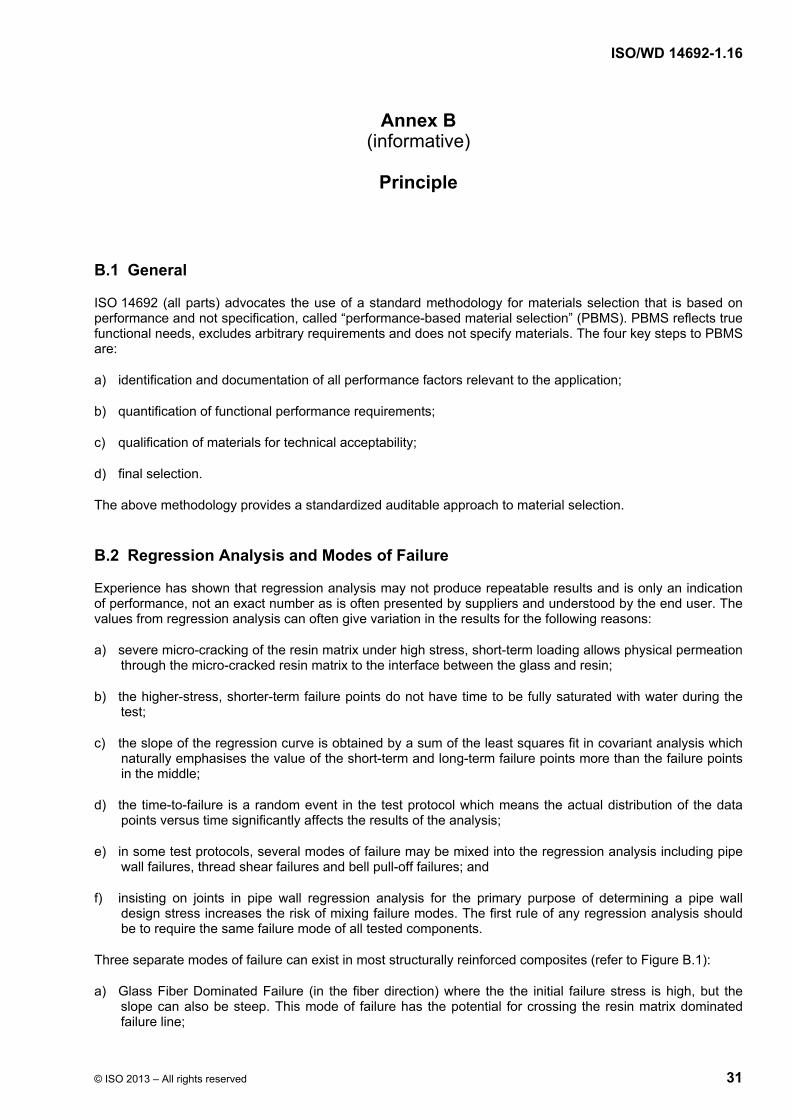
B.1 General
ISO 14692 (all parts) advocates the use of a standard methodology for materials selection that is based on performance and not specification, called “performance-based material selection” (PBMS). PBMS reflects true functional needs, excludes arbitrary requirements and does not specify materials. The four key steps to PBMS are:
a) identification and documentation of all performance factors relevant to the application;
b) quantification of functional performance requirements;
c) qualification of materials for technical acceptability;
d) final selection.
The above methodology provides a standardized auditable approach to material selection.
B.2 Regression Analysis and Modes of Failure
Experience has shown that regression analysis may not produce repeatable results and is only an indication of performance, not an exact number as is often presented by suppliers and understood by the end user. The values from regression analysis can often give variation in the results for the following reasons:
a) severe micro-cracking of the resin matrix under high stress, short-term loading allows physical permeation through the micro-cracked resin matrix to the interface between the glass and resin;
b) the higher-stress, shorter-term failure points do not have time to be fully saturated with water during the test;
c) the slope of the regression curve is obtained by a sum of the least squares fit in covariant analysis which naturally emphasises the value of the short-term and long-term failure points more than the failure points in the middle;
d) the time-to-failure is a random event in the test protocol which means the actual distribution of the data points versus time significantly affects the results of the analysis;
e) in some test protocols, several modes of failure may be mixed into the regression analysis including pipe wall failures, thread shear failures and bell pull-off failures; and
f) insisting on joints in pipe wall regression analysis for the primary purpose of determining a pipe wall design stress increases the risk of mixing failure modes. The first rule of any regression analysis should be to require the same failure mode of all tested components.
Three separate modes of failure can exist in most structurally reinforced composites (refer to Figure B.1):
a) Glass Fiber Dominated Failure (in the fiber direction) where the the initial failure stress is high, but the slope can also be steep. This mode of failure has the potential for crossing the resin matrix dominated failure line;

ISO/WD 14692-1.16
32 © ISO 2013 – All rights reserved
b) Resin Matrix Dominated Failure (perpendicular to the fiber direction) which is the most common mode for ±54 degree laminates and is most often the dominate failure mode in the short term and medium term. The degradation rate is slower than the fiber degradation rate, but the initial failure stress is lower, so this line can cross the glass fiber dominated line;
c) Interlaminar or Intralaminar Shear Failure (parallel to the fiber) which has the potential to occur in any item where shear dominates such as the thread shear for an 8-round joint. The initial value can be low, depending on geometry, but the degradation rate is low. The simple reason for the slow degradation rate is that the load is parallel to the fiber which means there is lot of cross-sectional area, so the shear stress applied to the fiber interface is low and the resulting degradation rate is low (shallow slope).
Key
1 Theoretical Resin Matrix Dominated Failure Regression Line
2 Theoretical Shear Dominated Failure Regression Line
3 Theoretical Glass Fiber Dominated Failure Regression Line
Figure B.1 — Modes of failure
Resin matrix dominated failure will be the limiting design stress for all pipe and fittings for most if not all of the design life. As such, conservative or reasonable regression gradients that are based on resin matrix dominated modes of failure are the most representative for predicting long term performance of the overall pipe and fitting system. Thread shear has a lower gradient than cross ply resin matrix cracking and can be the initial mode of failure for a joint. It is, however, reasonable that this regression will cross over the resin matrix dominated regression long term, but this is dependent on the geometry and ratio of shear to cross ply stress values.
NOTE Although the potential for fiber dominated failure exists for E-glass, it may not exist for boron-free E-glass since the failure stresses for boron-free E-glass would be higher and its fiber dominated failure line may not cross the resin matrix dominated failure line. Note: The gradient, or slope, of the regression line is shallower for boron-free E-glass, not the initial failure stress.

ISO/WD 14692-1.16
© ISO 2013 – All rights reserved 33
NOTE Regression gradients for fittings may be different than for pipe. However, cross ply resin matrix cracking will exist in all joints and fittings, so the gradients may not be that different. The effort to develop regression values for all components at all temperatures is not feasible, especially when mandated for each resin system and each factory. The use of representative default gradients and 1 000 h qualification tests for all components makes the task at least manageable.
B.2.1 Justification for a resin-matrix failure mode
A uni-directionally loaded composite can and will likely demonstrate glass fiber rupture (both long-term and short-term). In fact, a 54-degree pipe will show a fiber dominated “rupture” in short-term testing when loaded in the pure hoop direction, but there is a transition to resin matrix failures at certain R-ratios.
There are many composite “global” failure theories for composite structures. The “global” failure criteria proposed by various researchers are typically quadratic equations with terms for principle stresses, shear and an “interaction factor” . Researchers such as Puck, Halphin, Tsai have proposed various failure criteria. However, “global” failure criteria such as Puppo/Evensen, Puck and others usually only work for part of the trapezoidal failure envelope, because they are anticipating a particular mode of failure. Therefore, the prediction model has to change if a different mode of failure is encountered at different R-ratio’s. Some models accurately predict fiber dominated failure under pure hoop loading, but are not accurate for resin matrix dominated failure between R=0 to R ≈ 3. Other models accurately predict resin matrix dominated failure between R=0 and R ≈ 3, but not fiber dominated failure under pure hoop loading. The simple answer is the prediction model must anticipate the mode of failure. All current laminte plate theory prediction models only predict short term failure and cannot predict long term degradation rates without testing.
The jurisdiction of ISO 14692 has been limited to restrained joint pipe that produces large axial stresses from internal pressure. Bi-directionally loaded pipe will produce resin-matrix dominated failures at R-ratios between R=1 and R=4. The simple reason is the failure strain transverse to the fiber is much lower than the failure strain in the direction of the fiber. There are significant strains transverse to the fibers for loading between R=1 to R=4. Strain in the fiber in the plus ply direction produces strain transverse to the fibers in the adjacent minus ply direction in ±54-degree pipe. If you now imagine a dual angle pipe with hoop glass and longitudinal glass reinforcement, an R-ratio between 1 and 2 will produce large strains transverse to the hoop plies from axial stress and large strains transverse to the longitudinal plies from hoop stress, resulting in transverse cracking in both plies and resulting weep leakage. Only at extreme R-ratios, is it possible to produce fiber dominated failures.
B.2.2 Crack Propagation in Resin Matrix Dominated Failures
A fracture mechanics approach can accurately predict cracking in a ply parallel to the fibers (caused by loading transverse in the fiber direction), resulting in weep on a 54-degree filament wound pipe. The fracture energy balance is the increased stored energy in the cracked composite versus the fracture energy required to crack a ply. If the change in stored strain energy in the cracked composite vs. the un-cracked composite is greater than the fracture energy required to crack the ply from transverse loading, the cracks will generate in the ply. The equations for stored strain energy are similar to stored energy in a deflected spring.
The fracture energy required for a crack to propagate will degrade with time by swelling of the resin matrix and a chemical breakdown of the bond between the resin and fibers (hydrolysis). Water can quickly permeate a resin matrix without any physical cracks. The water molecules can permeate to the interface and attack the bond, so the degradation rate is still there, even at low applied strain levels with little or no cracking. Review of virtually all regression data shows a steeper slope for data points above 1 000 h where the crack density is much lower. The reason is the data points above 1 000 h more closely represent the regression slope from permeation and not from substantial micro cracking for the earlier data points. The micro cracking in the earlier data points (less than 1 000 h) causes the laminate to degrade faster due to high crack density providing physical paths for water permeation and the resulting faster degradation of the remaining laminate.
It is correct that a static load may not cause a crack of a certain size to propagate to failure. However, long term regression per ASTM D2992 with potable water is not a static condition. Thus, within the scope of this document, there is not a strain limit below which cracks can not propagate. Furthermore, the size of the crack is not static. When that crack increases beyond a certain critical length, it can propagate until failure occurs.

ISO/WD 14692-1.16
34 © ISO 2013 – All rights reserved
B.3 Gradient Choices
Default Gradients: Extensive pipe wall regression data (ASTM D2992) was reviewed in drafting this specification and arriving at the tabled Default Gradients. The published default gradients are believed representative of typical plain pipe performance and conservative for components and joints, thus a component qualification program based on all components (pipe, joints, fittings) surviving 1 000 h tests per default gradients is deemed an overall conservative approach. For this approach to be valid, joints, fittings, and components other than plain pipe must have a shallower regression slope than the pipe default values published here. Note the default gradients still allow a supplier to demonstrate superior performance by the absulute pressure used in the 1 000 h qualification tests, thus maintaining the performance based testing fundamental to ISO 14692.
Measured Gradients: ASTM D2992 allows for long term joint and component performance to be measured separately from pipe walls. API 15HR specifies a standard joint API round threads (a prescribed Joint) and allows for component qualification based on the fact that components and joints may have a shallower Gradient than the pipe wall. To qualify the shallower gradient components (joints and fittings) a Pressure Design Basis (PDB) of joints and components must be shown to be greater than the pipe PDB of the pipe wall at maximum temperature and life expectancy. Although more onerous than default gradient survival testing, this qualification method is acceptable if the manufacturer opts to perform the additional testing required per Part 2.
Figure B.2 — Illustration of qualifying components with pre-scribed joints
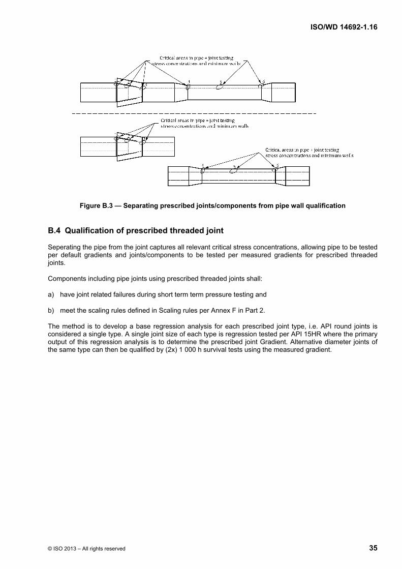
ISO/WD 14692-1.16
© ISO 2013 – All rights reserved 35
Figure B.3 — Separating prescribed joints/components from pipe wall qualification
B.4 Qualification of prescribed threaded joint
Seperating the pipe from the joint captures all relevant critical stress concentrations, allowing pipe to be tested per default gradients and joints/components to be tested per measured gradients for prescribed threaded joints.
Components including pipe joints using prescribed threaded joints shall:
a) have joint related failures during short term term pressure testing and
b) meet the scaling rules defined in Scaling rules per Annex F in Part 2.
The method is to develop a base regression analysis for each prescribed joint type, i.e. API round joints is considered a single type. A single joint size of each type is regression tested per API 15HR where the primary output of this regression analysis is to determine the prescribed joint Gradient. Alternative diameter joints of the same type can then be qualified by (2x) 1 000 h survival tests using the measured gradient.

ISO/WD 14692-1.16
36 © ISO 2013 – All rights reserved
Annex C (informative)
Guidance on Scope Limitations
Guidelines for determining if ISO14692 (all parts) is applicable to a product may be found in Figure C.1.
Figure C.1 — Flowchart for verifying the applicability of ISO 14692
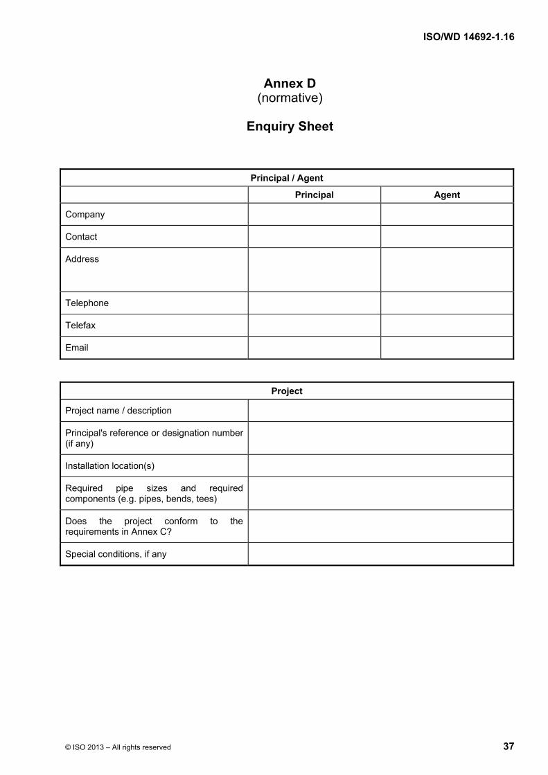
ISO/WD 14692-1.16
© ISO 2013 – All rights reserved 37
Annex D (normative)
Enquiry Sheet
Principal / Agent
Principal Agent
Company
Contact
Address
Telephone
Telefax
Project
Project name / description
Principal's reference or designation number (if any)
Installation location(s)
Required pipe sizes and required components (e.g. pipes, bends, tees)
Does the project conform to the requirements in Annex C?
Special conditions, if any
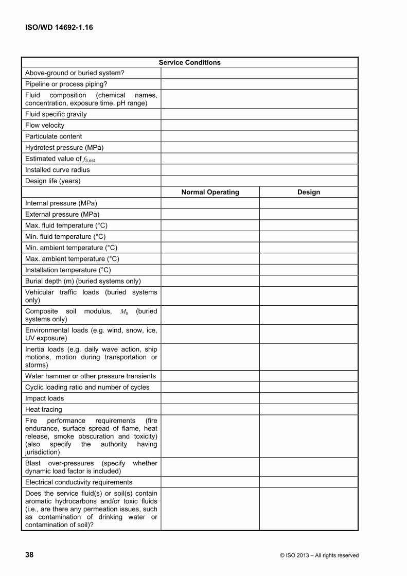
ISO/WD 14692-1.16
38 © ISO 2013 – All rights reserved
Service Conditions
Above-ground or buried system?
Pipeline or process piping?
Fluid composition (chemical names, concentration, exposure time, pH range)
Fluid specific gravity
Flow velocity
Particulate content
Hydrotest pressure (MPa)
Estimated value of f3,est
Installed curve radius
Design life (years)
Normal Operating Design
Internal pressure (MPa)
External pressure (MPa)
Max. fluid temperature (°C)
Min. fluid temperature (°C)
Min. ambient temperature (°C)
Max. ambient temperature (°C)
Installation temperature (°C)
Burial depth (m) (buried systems only)
Vehicular traffic loads (buried systems only)
Composite soil modulus, Ms (buried systems only)
Environmental loads (e.g. wind, snow, ice, UV exposure)
Inertia loads (e.g. daily wave action, ship motions, motion during transportation or storms)
Water hammer or other pressure transients
Cyclic loading ratio and number of cycles
Impact loads
Heat tracing
Fire performance requirements (fire endurance, surface spread of flame, heat release, smoke obscuration and toxicity) (also specify the authority having jurisdiction)
Blast over-pressures (specify whether dynamic load factor is included)
Electrical conductivity requirements
Does the service fluid(s) or soil(s) contain aromatic hydrocarbons and/or toxic fluids (i.e., are there any permeation issues, such as contamination of drinking water or contamination of soil)?
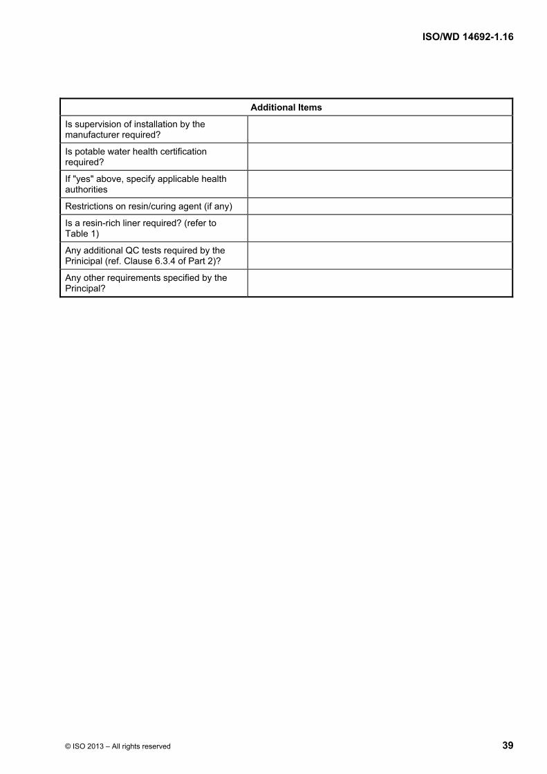
ISO/WD 14692-1.16
© ISO 2013 – All rights reserved 39
Additional Items
Is supervision of installation by the manufacturer required?
Is potable water health certification required?
If "yes" above, specify applicable health authorities
Restrictions on resin/curing agent (if any)
Is a resin-rich liner required? (refer to Table 1)
Any additional QC tests required by the Prinicipal (ref. Clause 6.3.4 of Part 2)?
Any other requirements specified by the Principal?

ISO/WD 14692-1.16
40 © ISO 2013 – All rights reserved
Annex E (normative)
Wall Thickness Definitions
Figure E.1 – Wall thickness definitions
2
IDODt
(E.1)
slr tttt (E.2)
lr 2 tIDID (E.3)
minr,rminr, 2 tIDOD (E.4)
minr,rminr, tIDD (E.5)
r
minr,r%vart
ttt
(E.6)
2i 4
IDA
(E.7)
)(4
2r
2minr,r IDODA
(E.8)
)(64
4r
4minr,r IDODI
(E.9)
minr,
4r
4minr,
r)(
32 OD
IDODZ
(E.10)
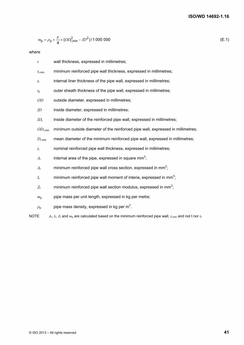
ISO/WD 14692-1.16
© ISO 2013 – All rights reserved 41
0000001/)(4
22minr,pp IDODm
(E.1)
where
t wall thickness, expressed in millimetres;
tr,min minimum reinforced pipe wall thickness, expressed in millimetres;
tl internal liner thickness of the pipe wall, expressed in millimetres;
ts outer sheath thickness of the pipe wall, expressed in millimetres;
OD outside diameter, expressed in millimetres;
ID inside diameter, expressed in millimetres;
IDr inside diameter of the reinforced pipe wall, expressed in millimetres;
ODr,min minimum outside diameter of the reinforced pipe wall, expressed in millimetres;
Dr,min mean diameter of the minimum reinforced pipe wall, expressed in millimetres;
tr nominal reinforced pipe wall thickness, expressed in millimetres;
Ai internal area of the pipe, expressed in square mm2;
Ar minimum reinforced pipe wall cross section, expressed in mm2;
Ir minimum reinforced pipe wall moment of interia, expressed in mm4;
Zr minimum reinforced pipe wall section modulus, expressed in mm3;
mp pipe mass per unit length, expressed in kg per metre;
p pipe mass density, expressed in kg per m3.
NOTE Ar, Ir, Zr and mp are calculated based on the minimum reinforced pipe wall, tr,min and not t nor tr.
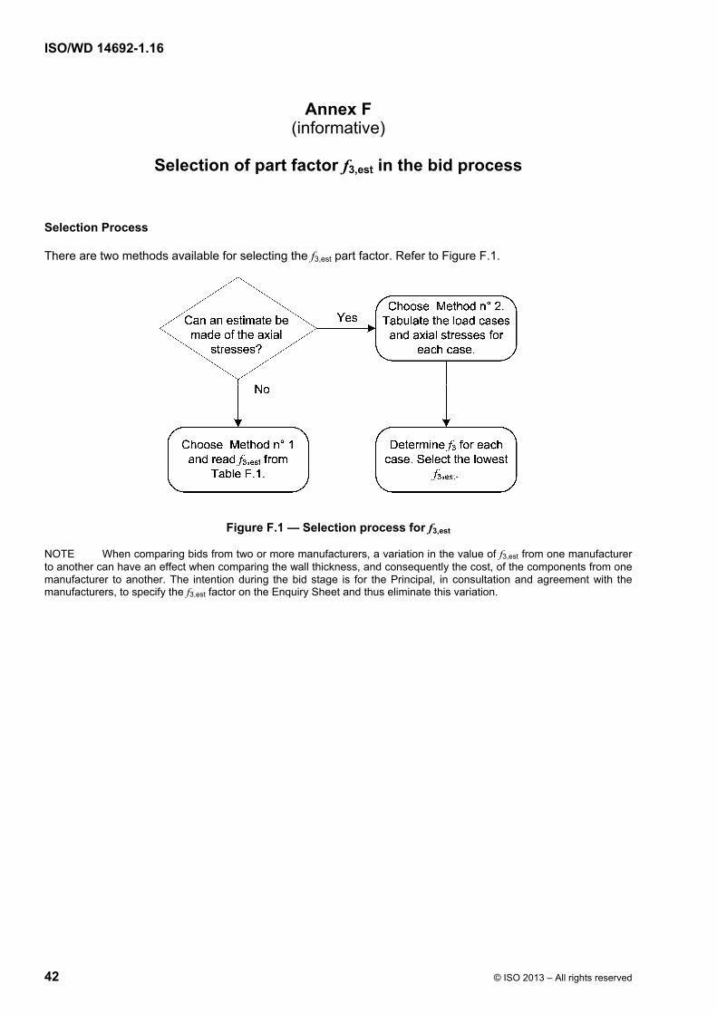
ISO/WD 14692-1.16
42 © ISO 2013 – All rights reserved
Annex F (informative)
Selection of part factor f3,est in the bid process
Selection Process
There are two methods available for selecting the f3,est part factor. Refer to Figure F.1.
Figure F.1 — Selection process for f3,est
NOTE When comparing bids from two or more manufacturers, a variation in the value of f3,est from one manufacturer to another can have an effect when comparing the wall thickness, and consequently the cost, of the components from one manufacturer to another. The intention during the bid stage is for the Principal, in consultation and agreement with the manufacturers, to specify the f3,est factor on the Enquiry Sheet and thus eliminate this variation.
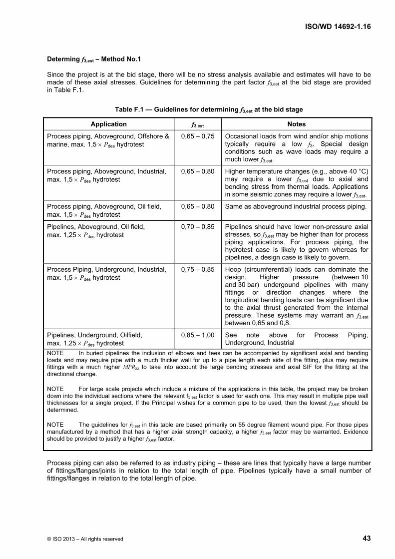
ISO/WD 14692-1.16
© ISO 2013 – All rights reserved 43
Determing f3,est – Method No.1
Since the project is at the bid stage, there will be no stress analysis available and estimates will have to be made of these axial stresses. Guidelines for determining the part factor f3,est at the bid stage are provided in Table F.1.
Table F.1 — Guidelines for determining f3,est at the bid stage
Application f3,est Notes
Process piping, Aboveground, Offshore & marine, max. 1,5 Pdes hydrotest
0,65 – 0,75 Occasional loads from wind and/or ship motions typically require a low f3. Special design conditions such as wave loads may require a much lower f3,est.
Process piping, Aboveground, Industrial, max. 1,5 Pdes hydrotest
0,65 – 0,80 Higher temperature changes (e.g., above 40 °C) may require a lower f3,est due to axial and bending stress from thermal loads. Applications in some seismic zones may require a lower f3,est.
Process piping, Aboveground, Oil field, max. 1,5 Pdes hydrotest
0,65 – 0,80 Same as aboveground industrial process piping.
Pipelines, Aboveground, Oil field, max. 1,25 Pdes hydrotest
0,70 – 0,85 Pipelines should have lower non-pressure axial stresses, so f3,est may be higher than for process piping applications. For process piping, the hydrotest case is likely to govern whereas for pipelines, a design case is likely to govern.
Process Piping, Underground, Industrial, max. 1,5 Pdes hydrotest
0,75 – 0,85 Hoop (circumferential) loads can dominate the design. Higher pressure (between 10 and 30 bar) undergound pipelines with many fittings or direction changes where the longitudinal bending loads can be significant due to the axial thrust generated from the internal pressure. These systems may warrant an f3,est between 0,65 and 0,8.
Pipelines, Underground, Oilfield, max. 1,25 Pdes hydrotest
0,85 – 1,00 See note above for Process Piping, Underground, Industrial
NOTE In buried pipelines the inclusion of elbows and tees can be accompanied by significant axial and bending loads and may require pipe with a much thicker wall for up to a pipe length each side of the fitting, plus may require fittings with a much higher MPRxx to take into account the large bending stresses and axial SIF for the fitting at the directional change.
NOTE For large scale projects which include a mixture of the applications in this table, the project may be broken down into the individual sections where the relevant f3,est factor is used for each one. This may result in multiple pipe wall thicknesses for a single project. If the Principal wishes for a common pipe to be used, then the lowest f3,est should be determined.
NOTE The guidelines for f3,est in this table are based primarily on 55 degree filament wound pipe. For those pipes manufactured by a method that has a higher axial strength capacity, a higher f3,est factor may be warranted. Evidence should be provided to justify a higher f3,est factor.
Process piping can also be referred to as industry piping – these are lines that typically have a large number of fittings/flanges/joints in relation to the total length of pipe. Pipelines typically have a small number of fittings/flanges in relation to the total length of pipe.

ISO/WD 14692-1.16
44 © ISO 2013 – All rights reserved
NOTE In undergound piping systems (both pipelines and process piping) where the soil and live loads can be significant, it may be necessary to select a product with an MPRxx higher than what is needed for internal pressure alone. In this instance, predict the deflection due to the soil and live loads and then calculate the hoop bending stress and hoop pressure stress. Then determine the equivalent pressure necessary to generate the same hoop stress. This can be done in the early stages of the project so that an appropriate MPRxx and product can be selected.
Determing f3,est – Method No.2
The second method for determining f3,est at the bid stage is to consider the non pressure-generated axial stresses that could occur on the piping system. Non pressure-generated axial stresses arise from :
a) ab;
b) ac;
c) af; and
d) at.
It should be possible to estimate typical values for these axial stresses for the proposed pipe installation. The first step is to identify a suitable GRP product type and a typical associated long term axial strength, a,LT,0:1,xx. This can be obtained from published vendor data. A value of 36,0 MPa is used in the example below.
The second step is to identify likely partial factors for critical design cases and the effect these will have on the design strength of the pipe material.
Table F.2 — Example of a summary of critical design cases
Case 1
(sustained)
Case 2
(sustained + self-limiting)
Case 3
(occasional)
Case 4
(hydrotest)
a,LT,0:1,xx 36,0 36,0 36,0 36,0
f2 0,67 0,83 0,89 0,89
A0 1,00 1,00 1,00 1,00
A2 1,00 1,00 1,00 1,00
A3 1,00 1,00 1,00 1,00
a,des,0:1 24,1 29,9 32,0 32,0
Now estimated values must be provided for the non pressure axail stresses for each load case. Values may be obtained through past design experience or through simple manual calculations for pipe support spans, roping curvature, etc.

ISO/WD 14692-1.16
© ISO 2013 – All rights reserved 45
Table F.3 — Descriptions of non pressure-generated axial stresses
Case 1
(sustained)
Case 2
(sustained + self-limiting)
Case 3
(occasional)
Case 4
(hydrotest)
ab Note 1 Note 1 Note 2 Note 1
ac Note 3 Note 4 Note 4 Note 4
af Note 5 Note 6 Note 7 Note 8
at Note 9 Note 10 Note 10 Note 11
NOTE 1 Usually bending from self weight at maximum unsupported span.
NOTE 2 Adds occasional loads such as wind or earthquake.
NOTE 3 Zero, since stresses from roping are not a sustained load.
NOTE 4 Bending stress from roping.
NOTE 5 Externally applied axial forces such as self weight in a vertical run of piping.
NOTE 6 Sustained loads plus other externally applied forces such as a reaction at a thrust block, friction at pipe supports.
NOTE 7 May be different than case 2 because of pressure surges that cause axial expansion.
NOTE 8 Will generally be higher than case 2 or 3 due to the higher pressure from the hydrotest.
NOTE 9 Zero, since stresses from temperature changes are not a sustained load.
NOTE 10 Includes bending in expansion loop or reaction to thrust blocks from temperature changes.
NOTE 11 Typically zero since the hydrotest is at ambient temperature.
Table F.4 — Example of non pressure-generated axial stresses
Case 1
(sustained)
Case 2
(sustained + self-limiting)
Case 3
(occasional)
Case 4
(hydrotest)
ab 8,0 8,0 8,0 8,0
ac 0,0 0,0 0,0 0,0
af 0,0 1,0 1,0 5,0
at 0,0 1,0 3,0 0,0
Values for f3,est can now be calculated for each design case.

ISO/WD 14692-1.16
46 © ISO 2013 – All rights reserved
Table F.5 — Example of a summary of critical design cases
Case 1
(sustained)
Case 2
(sustained + self-limiting)
Case 3
(occasional)
Case 4
(hydrotest)
a,des,0:1 24,1 29,9 32,0 32,0
ab + ac + af + at 8,0 10,0 12,0 13,0
f3,est 0,73 0,73 0,70 0,68
For the purposes of pipe selection use of the lowest of the identified f3,est values should be considered (in this example, 0,68). When selecting a pipe for the project, it is essential that the hydrotest be considered as a design case.
The equation for calculating f3,est in the previous table is:
8,0
11:des,0a,
atafacabest,3
f (F.1)
NOTE The value of 0,8 comes from equation D.10 in Annex D of Part 2. Since the Rtest data is at an R-ratio of 1,0 or less (actually 0,5 and 1,0) and if we expect that f3,est will be 0,5 or larger, then the 0,8 value is required so that we adjust along the slope of the line from R=Rtest to R=2.

ISO/WD 14692-1.16
© ISO 2013 – All rights reserved 47
Background
With isotropic materials, there is no need for an f3,est part factor since ap only uses half of the allowable axial stress on the design envelope. Refer to Figure F.2.
Key
1 Axial stress due to internal pressure, ap
2 Axial stress available for stresses from bending (ab), roping/curving (ac), external forces (af) and thermal loads (at)
Figure F.2 — Typical design envelope for an isotropic material
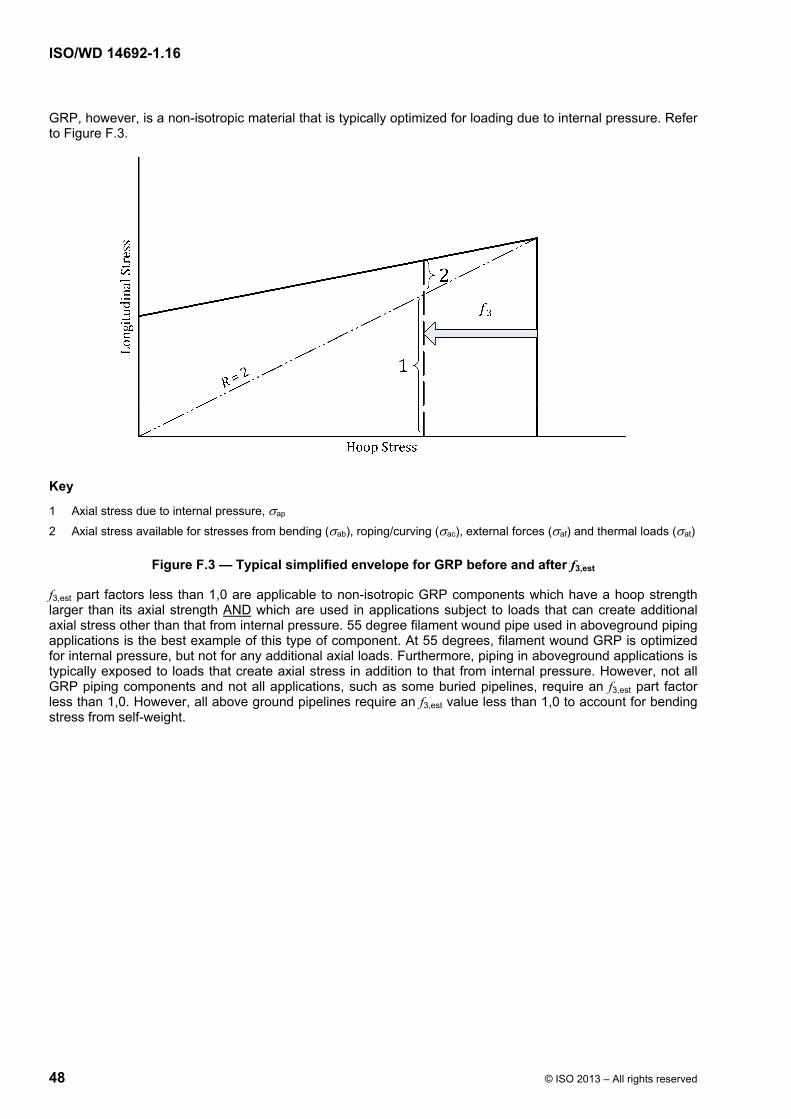
ISO/WD 14692-1.16
48 © ISO 2013 – All rights reserved
GRP, however, is a non-isotropic material that is typically optimized for loading due to internal pressure. Refer to Figure F.3.
Key
1 Axial stress due to internal pressure, ap
2 Axial stress available for stresses from bending (ab), roping/curving (ac), external forces (af) and thermal loads (at)
Figure F.3 — Typical simplified envelope for GRP before and after f3,est
f3,est part factors less than 1,0 are applicable to non-isotropic GRP components which have a hoop strength larger than its axial strength AND which are used in applications subject to loads that can create additional axial stress other than that from internal pressure. 55 degree filament wound pipe used in aboveground piping applications is the best example of this type of component. At 55 degrees, filament wound GRP is optimized for internal pressure, but not for any additional axial loads. Furthermore, piping in aboveground applications is typically exposed to loads that create axial stress in addition to that from internal pressure. However, not all GRP piping components and not all applications, such as some buried pipelines, require an f3,est part factor less than 1,0. However, all above ground pipelines require an f3,est value less than 1,0 to account for bending stress from self-weight.
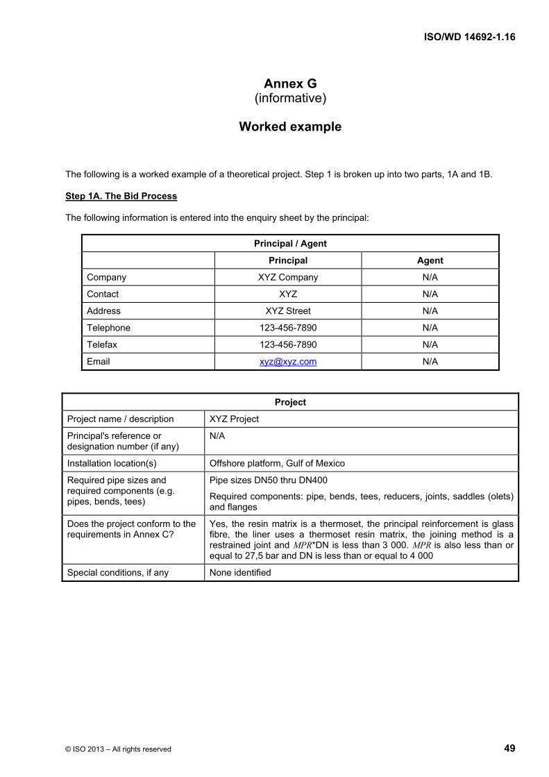
ISO/WD 14692-1.16
© ISO 2013 – All rights reserved 49
Annex G (informative)
Worked example
The following is a worked example of a theoretical project. Step 1 is broken up into two parts, 1A and 1B.
Step 1A. The Bid Process
The following information is entered into the enquiry sheet by the principal:
Principal / Agent
Principal Agent
Company XYZ Company N/A
Contact XYZ N/A
Address XYZ Street N/A
Telephone 123-456-7890 N/A
Telefax 123-456-7890 N/A
Email [email protected] N/A
Project
Project name / description XYZ Project
Principal's reference or designation number (if any)
N/A
Installation location(s) Offshore platform, Gulf of Mexico
Required pipe sizes and required components (e.g. pipes, bends, tees)
Pipe sizes DN50 thru DN400
Required components: pipe, bends, tees, reducers, joints, saddles (olets) and flanges
Does the project conform to the requirements in Annex C?
Yes, the resin matrix is a thermoset, the principal reinforcement is glass fibre, the liner uses a thermoset resin matrix, the joining method is a restrained joint and MPR*DN is less than 3 000. MPR is also less than or equal to 27,5 bar and DN is less than or equal to 4 000
Special conditions, if any None identified

ISO/WD 14692-1.16
50 © ISO 2013 – All rights reserved
Service Conditions Above-ground or buried system? Aboveground Pipeline or process piping? Process piping Fluid composition (chemical names, concentration, exposure time, pH range)
Seawater
Fluid specific gravity 1,03 Flow velocity <= 4 m/s Particulate content None identified Hydrotest pressure (MPa) 2,4 MPa f3,est To be determined with manufacturer Installed curve radius N/A Design life (years) 20 years Normal Operating Design Internal pressure (MPa) 1,0 1,6 External pressure (MPa) 0,074 0,1 (full vacuum) Max. fluid temperature (°C) 50 65 Min. fluid temperature (°C) 10 5 Min. ambient temperature (°C) 10 Max. ambient temperature (°C) 30 Installation temperature (°C) 10 to 30 Burial depth (m) (buried systems only)
N/A
Vehicular traffic loads (buried systems only)
N/A
Composite soil modulus, Ms (buried systems only)
N/A
Environmental loads (e.g. wind, snow, ice)
183 kph wind loads
Inertia loads (e.g. daily wave action, ship motions, motion during transportation or storms)
Not identified at this time, but inertia loads are expected due to platform motions
Water hammer or other pressure transients
Not identified at this time
Cyclic loading ratio and number of cycles
N/A
Impact loads Not quantified at this time; recommend minimum wall thickness of 5,0 mm
Heat tracing Not required Fire performance requirements (fire endurance, surface spread of flame, heat release, smoke obscuration and toxicity) (also specify the authority having jurisdiction)
Products are intended for use in applications requiring fire endurance, surviving a hydrocarbon impinging flame type fire for 30 min filled with stagnant water. During the test, slight weeping is acceptable. After cooling, leakage from the post-fire test shall be less than or equal to 0,2 lpm for a period of 15 min. There are no requirements for surface spread of flame, heat release, smoke obscuration nor toxicity
Blast over-pressures (specify whether dynamic load factor is included)
None identified
Electrical conductivity requirements Not required
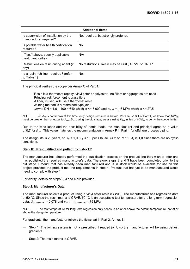
ISO/WD 14692-1.16
© ISO 2013 – All rights reserved 51
Additional Items
Is supervision of installation by the manufacturer required?
Not required, but strongly preferred
Is potable water health certification required?
No
If "yes" above, specify applicable health authorities
N/A
Restrictions on resin/curing agent (if any)
No restrictions. Resin may be GRE, GRVE or GRUP
Is a resin-rich liner required? (refer to Table 1)
No.
The principal verifies the scope per Annex C of Part 1:
Resin is a thermoset (epoxy, vinyl ester or polyester); no fillers or aggregates are used Principal reinforcement is glass fibre A liner, if used, will use a thermoset resin Joining method is a restrained type joint. MPR DN = 1,6 400 = 640 which is <= 3 000 and MPR = 1,6 MPa which is <= 27,5
NOTE MPRxx is not known at this time, only design pressure is known. Per Clause 3.1 of Part 1, we know that MPRxx must be greater than or equal to Pdes. So, during the bid stage, we are using Pdes in lieu of MPRxx to verify the scope limits.
Due to the wind loads and the possibility of inertia loads, the manufacturer and principal agree on a value of 0,7 for f3,est. This value matches the recommendation in Annex F in Part 1 for offshore process piping.
The design life is 20 years, so A0 = 1,0. A2 is 1,0 per Clause 3.4.2 of Part 2. A3 is 1,0 since there are no cyclic conditions.
Step 1B. Pre-qualified and pulled from stock?
The manufacturer has already performed the qualification process on the product line they wish to offer and has published the required manufacturer's data. Therefore, steps 2 and 3 have been completed prior to the bid stage. Product that has already been manufactured and is in stock would be available for use on this project provided the product met the requirements in step 4. Product that has yet to be manufactured would need to comply with step 4.
For clarity, details on steps 2, 3 and 4 are provided.
Step 2. Manufacturer's Data
The manufacturer selects a product using a vinyl ester resin (GRVE). The manufacturer has regression data at 50 °C. Since the resin matrix is GRVE, 50 °C is an acceptable test temperature for the long term regression data. G50,measured = 0,078 and h,LT,2:1,50,measured = 75 MPa.
NOTE The test temperature for long term regression only needs to be at or above the default temperature, not at or above the design temperature.
For gradients, the manufacturer follows the flowchart in Part 2, Annex B:
Step 1: The joining system is not a prescribed threaded joint, so the manufacturer will be using default gradients.
Step 2: The resin matrix is GRVE.
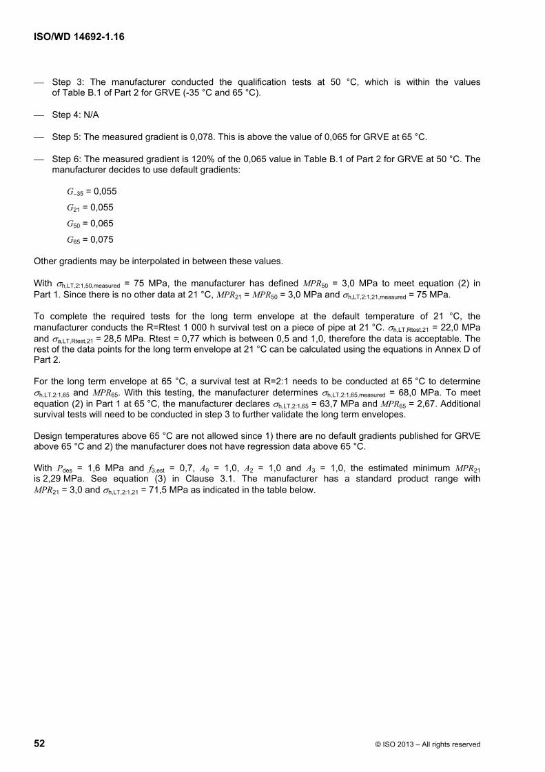
ISO/WD 14692-1.16
52 © ISO 2013 – All rights reserved
Step 3: The manufacturer conducted the qualification tests at 50 °C, which is within the values of Table B.1 of Part 2 for GRVE (-35 °C and 65 °C).
Step 4: N/A
Step 5: The measured gradient is 0,078. This is above the value of 0,065 for GRVE at 65 °C.
Step 6: The measured gradient is 120% of the 0,065 value in Table B.1 of Part 2 for GRVE at 50 °C. The manufacturer decides to use default gradients:
G–35 = 0,055
G21 = 0,055
G50 = 0,065
G65 = 0,075
Other gradients may be interpolated in between these values.
With h,LT,2:1,50,measured = 75 MPa, the manufacturer has defined MPR50 = 3,0 MPa to meet equation (2) in Part 1. Since there is no other data at 21 °C, MPR21 = MPR50 = 3,0 MPa and h,LT,2:1,21,measured = 75 MPa.
To complete the required tests for the long term envelope at the default temperature of 21 °C, the manufacturer conducts the R=Rtest 1 000 h survival test on a piece of pipe at 21 °C. h,LT,Rtest,21 = 22,0 MPa and a,LT,Rtest,21 = 28,5 MPa. Rtest = 0,77 which is between 0,5 and 1,0, therefore the data is acceptable. The rest of the data points for the long term envelope at 21 °C can be calculated using the equations in Annex D of Part 2.
For the long term envelope at 65 °C, a survival test at R=2:1 needs to be conducted at 65 °C to determine h,LT,2:1,65 and MPR65. With this testing, the manufacturer determines h,LT,2:1,65,measured = 68,0 MPa. To meet equation (2) in Part 1 at 65 °C, the manufacturer declares h,LT,2:1,65 = 63,7 MPa and MPR65 = 2,67. Additional survival tests will need to be conducted in step 3 to further validate the long term envelopes.
Design temperatures above 65 °C are not allowed since 1) there are no default gradients published for GRVE above 65 °C and 2) the manufacturer does not have regression data above 65 °C.
With Pdes = 1,6 MPa and f3,est = 0,7, A0 = 1,0, A2 = 1,0 and A3 = 1,0, the estimated minimum MPR21 is 2,29 MPa. See equation (3) in Clause 3.1. The manufacturer has a standard product range with MPR21 = 3,0 and h,LT,2:1,21 = 71,5 MPa as indicated in the table below.
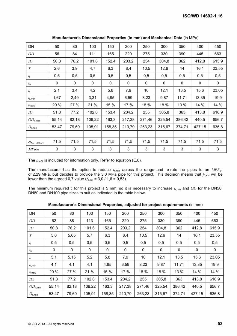
ISO/WD 14692-1.16
© ISO 2013 – All rights reserved 53
Manufacturer's Dimensional Properties (in mm) and Mechanical Data (in MPa)
DN 50 80 100 150 200 250 300 350 400 450
OD 56 84 111 165 220 275 330 390 445 663
ID 50,8 76,2 101,6 152,4 203,2 254 304,8 362 412,8 615,9
T 2,6 3,9 4,7 6,3 8,4 10,5 12,6 14 16,1 23,55
tl 0,5 0,5 0,5 0,5 0,5 0,5 0,5 0,5 0,5 0,5
ts 0 0 0 0 0 0 0 0 0 0
tr 2,1 3,4 4,2 5,8 7,9 10 12,1 13,5 15,6 23,05
tr,min 1,67 2,49 3,31 4,95 6,59 8,23 9,87 11,71 13,35 19,9
tvar% 20 % 27 % 21 % 15 % 17 % 18 % 18 % 13 % 14 % 14 %
IDr 51,8 77,2 102,6 153,4 204,2 255 305,8 363 413,8 616,9
ODr,min 55,14 82,18 109,22 163,3 217,38 271,46 325,54 386,42 440,5 656,7
Dr,min 53,47 79,69 105,91 158,35 210,79 263,23 315,67 374,71 427,15 636,8
h,LT,2:1,21 71,5 71,5 71,5 71,5 71,5 71,5 71,5 71,5 71,5 71,5
MPR21 3 3 3 3 3 3 3 3 3 3
The tvar% is included for information only. Refer to equation (E.6).
The manufacturer has the option to reduce tr,min across the range and re-rate the pipes to an MPR21 of 2,29 MPa, but decides to provide the 3,0 MPa pipe for this project. This decision means that f3,est will be lower than the agreed 0,7 value (f3,est = 3,0 / 1,6 = 0,53).
The minimum required tr for this project is 5 mm, so it is necessary to increase tr,min and OD for the DN50, DN80 and DN100 pipe sizes to suit as indicated in the table below.
Manufacturer's Dimensional Properties, adjusted for project requirements (in mm)
DN 50 80 100 150 200 250 300 350 400 450
OD 62 88 113 165 220 275 330 390 445 663
ID 50,8 76,2 101,6 152,4 203,2 254 304,8 362 412,8 615,9
T 5,6 5,65 5,7 6,3 8,4 10,5 12,6 14 16,1 23,55
tl 0,5 0,5 0,5 0,5 0,5 0,5 0,5 0,5 0,5 0,5
ts 0 0 0 0 0 0 0 0 0 0
tr 5,1 5,15 5,2 5,8 7,9 10 12,1 13,5 15,6 23,05
tr,min 4,1 4,1 4,1 4,95 6,59 8,23 9,87 11,71 13,35 19,9
tvar% 20 % 27 % 21 % 15 % 17 % 18 % 18 % 13 % 14 % 14 %
IDr 51,8 77,2 102,6 153,4 204,2 255 305,8 363 413,8 616,9
ODr,min 55,14 82,18 109,22 163,3 217,38 271,46 325,54 386,42 440,5 656,7
Dr,min 53,47 79,69 105,91 158,35 210,79 263,23 315,67 374,71 427,15 636,8
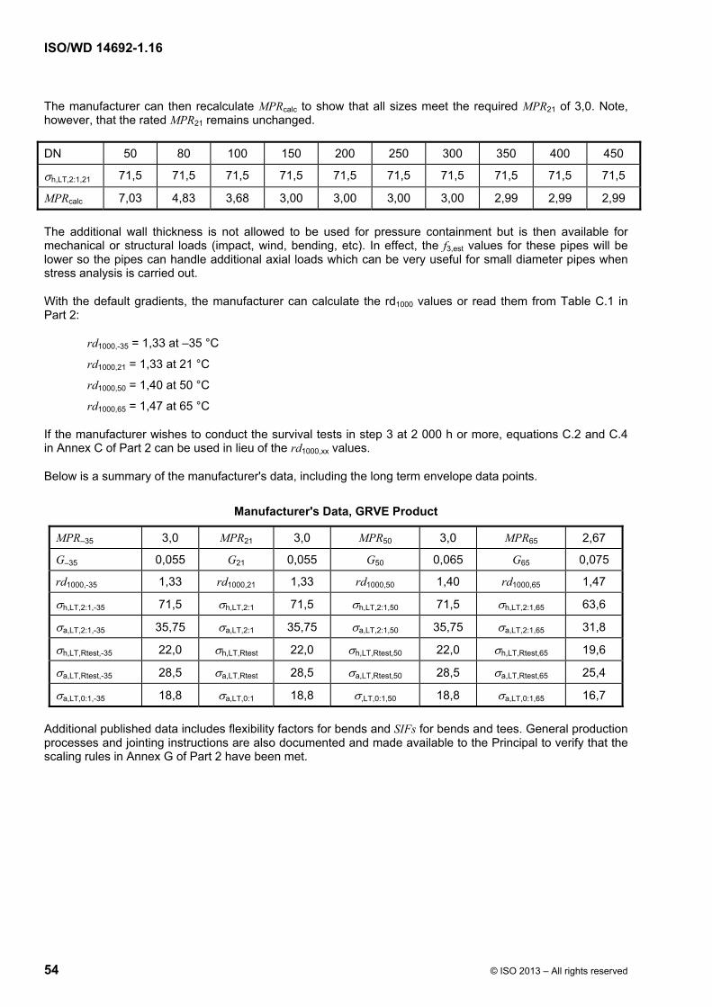
ISO/WD 14692-1.16
54 © ISO 2013 – All rights reserved
The manufacturer can then recalculate MPRcalc to show that all sizes meet the required MPR21 of 3,0. Note, however, that the rated MPR21 remains unchanged.
DN 50 80 100 150 200 250 300 350 400 450
h,LT,2:1,21 71,5 71,5 71,5 71,5 71,5 71,5 71,5 71,5 71,5 71,5
MPRcalc 7,03 4,83 3,68 3,00 3,00 3,00 3,00 2,99 2,99 2,99
The additional wall thickness is not allowed to be used for pressure containment but is then available for mechanical or structural loads (impact, wind, bending, etc). In effect, the f3,est values for these pipes will be lower so the pipes can handle additional axial loads which can be very useful for small diameter pipes when stress analysis is carried out.
With the default gradients, the manufacturer can calculate the rd1000 values or read them from Table C.1 in Part 2:
rd1000,-35 = 1,33 at –35 °C
rd1000,21 = 1,33 at 21 °C
rd1000,50 = 1,40 at 50 °C
rd1000,65 = 1,47 at 65 °C
If the manufacturer wishes to conduct the survival tests in step 3 at 2 000 h or more, equations C.2 and C.4 in Annex C of Part 2 can be used in lieu of the rd1000,xx values.
Below is a summary of the manufacturer's data, including the long term envelope data points.
Manufacturer's Data, GRVE Product
MPR–35 3,0 MPR21 3,0 MPR50 3,0 MPR65 2,67
G–35 0,055 G21 0,055 G50 0,065 G65 0,075
rd1000,-35 1,33 rd1000,21 1,33 rd1000,50 1,40 rd1000,65 1,47
h,LT,2:1,-35 71,5 h,LT,2:1 71,5 h,LT,2:1,50 71,5 h,LT,2:1,65 63,6
a,LT,2:1,-35 35,75 a,LT,2:1 35,75 a,LT,2:1,50 35,75 a,LT,2:1,65 31,8
h,LT,Rtest,-35 22,0 h,LT,Rtest 22,0 h,LT,Rtest,50 22,0 h,LT,Rtest,65 19,6
a,LT,Rtest,-35 28,5 a,LT,Rtest 28,5 a,LT,Rtest,50 28,5 a,LT,Rtest,65 25,4
a,LT,0:1,-35 18,8 a,LT,0:1 18,8 ,LT,0:1,50 18,8 a,LT,0:1,65 16,7
Additional published data includes flexibility factors for bends and SIFs for bends and tees. General production processes and jointing instructions are also documented and made available to the Principal to verify that the scaling rules in Annex G of Part 2 have been met.

ISO/WD 14692-1.16
© ISO 2013 – All rights reserved 55
Step 3. The Qualification Process
The component that was used in the long term regression testing was DN100, 3,5 MPa pipe. The manufacturer also has existing survival test data in the DN100 at 3,5 MPa, the DN300 size at 2,0 MPa and the DN600 size at 1,6 MPa. Per Annex F of Part 2, The DN100, 3,5 MPa data qualify sizes and MPRs per the following:
Data point #1: Per equation F.4 in Part 2, the maximum value for MPR2 is 1,6 × 3,5 or 5,6 bar. Note: equation F.4 applies, not F.3, because MPR1 is greater than 2,5 MPa.
The minimum pipe size is 0 per equation F.1. Note: equation F.1 applies, not F.2, because DN1 is less than or equal to 300 mm.
Data point #2: Per equation F.4 in Part 2, the minimum value for MPR2 is 0,5 3,5 or 1,75 MPa.
DN2 at data point #2 is the same as DN at data point #1.
Data point #3: Per equation F.1, the maximum value of DN2 is 1,6 100 or 160 mm. Note: equation F.1 applies, not F.2, because DN1 is less than or equal to 300 mm. However, there is also equation F.5. Per equation F.5 in Part 2, at MPR2 = 3,5 MPa, DN2 must be less than or equal to 100 3,5 / 1,6 or 218,75 mm. Comparing the two results, equation F.1 is the more restrictive in determining the maximum DN2. Therefore, the maximum pipe size that can be qualified with the DN100 size is 160 mm.
MPR2 at data point #3 is the same as MPR at data point #2.
Data point #4: Per equation F.4 in Part 2, the maximum value of MPR2 is 1,6 3,5 or 5,6 bar. However, there is also equation F.5. Per equation F.5 in Part 2, at DN2 = 160, MPR2 must be less than or equal to 100 3,5 / 160 = 2,1875 MPa.
DN2 at data point #4 is the same as DN at data point #3.
Data point #5: MPR2 at data point #5 is the same as DN at data point #1, which is 5,6 MPa.
To determine DN2, use equation F.5 in Part 2. At MPR2 = 56 bar, the maximum value of DN2 is 100 3,5 / 5,6 or 62,5 mm.
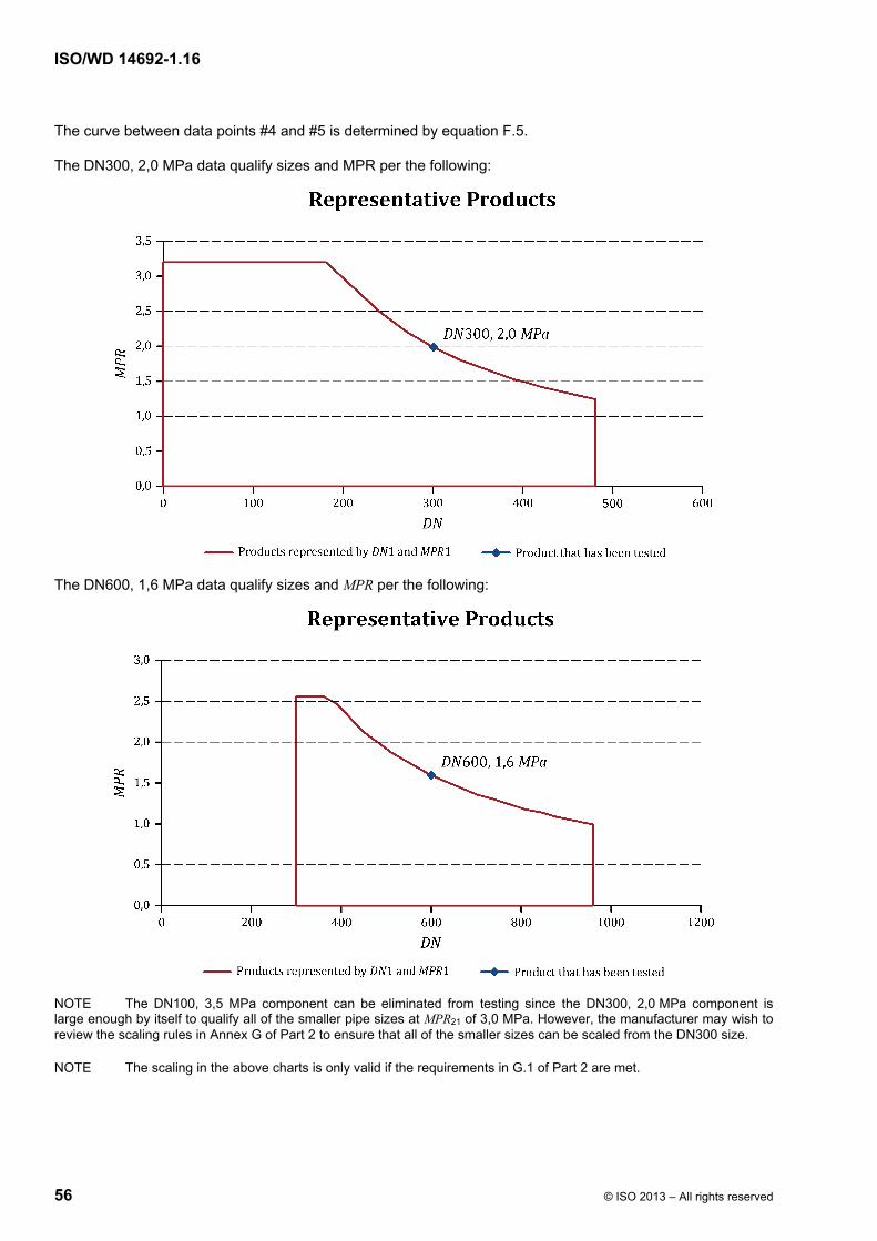
ISO/WD 14692-1.16
56 © ISO 2013 – All rights reserved
The curve between data points #4 and #5 is determined by equation F.5.
The DN300, 2,0 MPa data qualify sizes and MPR per the following:
The DN600, 1,6 MPa data qualify sizes and MPR per the following:
NOTE The DN100, 3,5 MPa component can be eliminated from testing since the DN300, 2,0 MPa component is large enough by itself to qualify all of the smaller pipe sizes at MPR21 of 3,0 MPa. However, the manufacturer may wish to review the scaling rules in Annex G of Part 2 to ensure that all of the smaller sizes can be scaled from the DN300 size.
NOTE The scaling in the above charts is only valid if the requirements in G.1 of Part 2 are met.

ISO/WD 14692-1.16
© ISO 2013 – All rights reserved 57
The manufacturer had conducted the survival tests at the standard 1 000 h time period. Since the design temperature is 65 °C, the manufacturer has the option to conduct only one set of survival tests at 65 °C. However, if this were the only set of tests to be conducted, then MPR21 = MPR50 = MPR65 = 2,67 MPa. The manufacturer wishes to utilize the MPR50 data of 3,0 MPa, therefore, the manufacturer would also need to conduct a set of survival tests at 50 °C.
NOTE Another option would be for the manufacturer to conduct survival tests at both 21 °C and 65 °C. In this case, MPR21 = 3,0, MPR65 = 2,67 and MPR50 = 2,78 MPa (3,0 – (50 – 21) / (65 – 21) * (3,0 – 2,67)).
For joints, bends, flanges, reducers and tees:
PT1 000,50 = 1,47 3,0 / 0,67 = 6,58 MPa = 65,8 bar
PT1 000,65 = 1,47 2,67 / 0,67 = 5,86 MPa = 58,6 bar
For pipes, the survival test pressure needed to be adjusted based on the actual wall thickness of the sample being tested. In the 300mm size, the manufacturer had estimated measurements of tr,min = 9,9 and Dr,min = 315,7. With the manufacturer's data of tr,act = 10,5 and Dr,act = 316,3, the manufacturer used equation C.1 in Part 2 to calculate:
PT1 000,50 = 1,47 3,0 / 0,67 (10,5 315,7) / (9,9 316,3) = 6,97 MPa = 69,7 bar
PT1 000,65 = 1,47 2,67 / 0,67 (10,5 315,7) / (9,9 316,3) = 6,20 MPa = 62,0 bar
If the manufacturer had conducted the survival test for all the 300mm components (pipe+joint, flange, bend, tee) at one time, the survival test pressures would have been 69,7 bar at 50 °C and 62,0 bar at 65 °C, since these are the larger of the pairs of values.
After the successful test, the manufacturer measured the actual wall thickness as tr,act = 10,9 mm. Since this is less than or equal to 105 % of 10,5 mm, the test result is considered acceptable.
In the 400 mm size, the manufacturer had taken dimensions of tr,min = 13,4 and Dr,min = 427,2. With the manufacturer's data of tr,act = 14,0 and Dr,act = 427,8, the manufacturer used equation 16 in Part 2 to calculate:
PT1 000,50 = 1,47 3,0 / 0,67 (14,0 427,2) / (13,4 427,8) = 6,87 MPa = 68,7 bar
PT1 000,65 = 1,47 2,67 / 0,67 (14,0 427,2) / (13,4 427,8) = 6,11 MPa = 61,1 bar
If the manufacturer had conducted the survival test for all the 400mm components (pipe+joint, flange, bend, tee) at one time, the survival test pressures would have been 68,7 bar at 50 °C and 61,1 bar at 65 °C since these are the larger of the pairs of values.
After the successful test, the manufacturer measured the actual wall thickness as tr,act = 14,5 mm. Since this is less than or equal to 105 % of 14,7 mm, the test result is considered acceptable.
Since the design temperature for this project is 65 °C, the manufacturer is required to supply determined elastic properties for the product at two different temperatures. Both temperatures must be 21 °C and one of them must be equal to or greater than the design temperature (65 °C).
The manufacturer has published elastic properties at 21 °C , 50 °C and 65 °C, which meets the requirements of the flowchart in Figure 3 of Part 2:
Ea = 10,0 GPa at 21 °C; 9,7 GPa at 50 °C; 9,2 GPa at 65 °C
Eh = 15,7 GPa at 21 °C; 15,2 GPa at 50 °C; 14,4 GPa at 65 °C
ah = 0,55 at 21 °C; 0,53 at 50 °C; 0,50 at 65 °C
ha = 0,35 at 21 °C; 0,34 at 50 °C; 0,32 at 65 °C
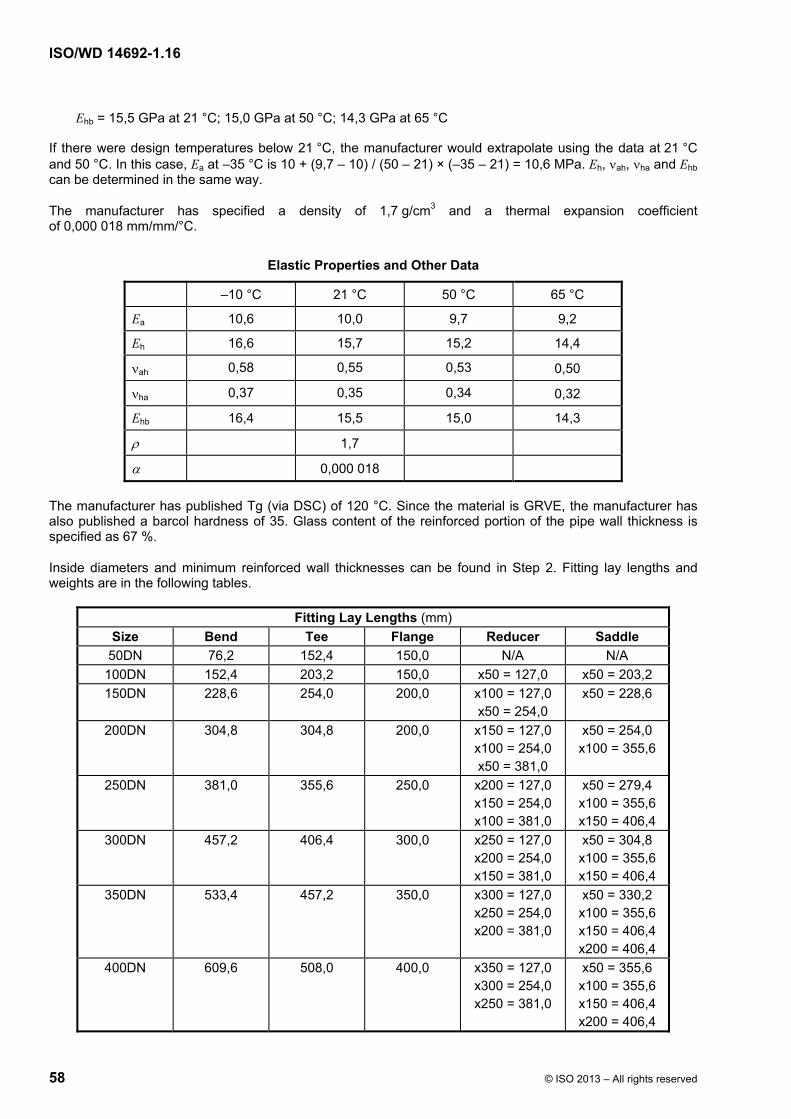
ISO/WD 14692-1.16
58 © ISO 2013 – All rights reserved
Ehb = 15,5 GPa at 21 °C; 15,0 GPa at 50 °C; 14,3 GPa at 65 °C
If there were design temperatures below 21 °C, the manufacturer would extrapolate using the data at 21 °C and 50 °C. In this case, Ea at –35 °C is 10 + (9,7 – 10) / (50 – 21) × (–35 – 21) = 10,6 MPa. Eh, ah, ha and Ehb can be determined in the same way.
The manufacturer has specified a density of 1,7 g/cm3 and a thermal expansion coefficient of 0,000 018 mm/mm/°C.
Elastic Properties and Other Data
–10 °C 21 °C 50 °C 65 °C
Ea 10,6 10,0 9,7 9,2
Eh 16,6 15,7 15,2 14,4
ah 0,58 0,55 0,53 0,50
ha 0,37 0,35 0,34 0,32
Ehb 16,4 15,5 15,0 14,3
1,7
0,000 018
The manufacturer has published Tg (via DSC) of 120 °C. Since the material is GRVE, the manufacturer has also published a barcol hardness of 35. Glass content of the reinforced portion of the pipe wall thickness is specified as 67 %.
Inside diameters and minimum reinforced wall thicknesses can be found in Step 2. Fitting lay lengths and weights are in the following tables.
Fitting Lay Lengths (mm)
Size Bend Tee Flange Reducer Saddle
50DN 76,2 152,4 150,0 N/A N/A
100DN 152,4 203,2 150,0 x50 = 127,0 x50 = 203,2
150DN 228,6 254,0 200,0 x100 = 127,0 x50 = 254,0
x50 = 228,6
200DN 304,8 304,8 200,0 x150 = 127,0 x100 = 254,0 x50 = 381,0
x50 = 254,0 x100 = 355,6
250DN 381,0 355,6 250,0 x200 = 127,0 x150 = 254,0 x100 = 381,0
x50 = 279,4 x100 = 355,6 x150 = 406,4
300DN 457,2 406,4 300,0 x250 = 127,0 x200 = 254,0 x150 = 381,0
x50 = 304,8 x100 = 355,6 x150 = 406,4
350DN 533,4 457,2 350,0 x300 = 127,0 x250 = 254,0 x200 = 381,0
x50 = 330,2 x100 = 355,6 x150 = 406,4 x200 = 406,4
400DN 609,6 508,0 400,0 x350 = 127,0 x300 = 254,0 x250 = 381,0
x50 = 355,6 x100 = 355,6 x150 = 406,4 x200 = 406,4
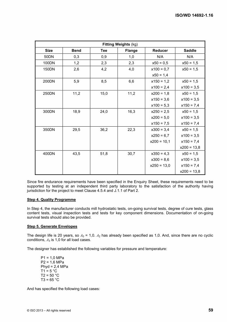
ISO/WD 14692-1.16
© ISO 2013 – All rights reserved 59
Fitting Weights (kg)
Size Bend Tee Flange Reducer Saddle
50DN 0,3 0,9 1,0 N/A N/A
100DN 1,2 2,3 2,3 x50 = 0,5 x50 = 1,5
150DN 2,6 4,2 4,0 x100 = 0,7
x50 = 1,4
x50 = 1,5
200DN 5,9 8,5 6,6 x150 = 1,2
x100 = 2,4
x50 = 1,5
x100 = 3,5
250DN 11,2 15,0 11,2 x200 = 1,8
x150 = 3,6
x100 = 5,3
x50 = 1,5
x100 = 3,5
x150 = 7,4
300DN 18,9 24,0 16,3 x250 = 2,5
x200 = 5,0
x150 = 7,5
x50 = 1,5
x100 = 3,5
x150 = 7,4
350DN 29,5 36,2 22,3 x300 = 3,4
x250 = 6,7
x200 = 10,1
x50 = 1,5
x100 = 3,5
x150 = 7,4
x200 = 13,8
400DN 43,5 51,8 30,7 x350 = 4,3
x300 = 8,6
x250 = 13,0
x50 = 1,5
x100 = 3,5
x150 = 7,4
x200 = 13,8
Since fire endurance requirements have been specified in the Enquiry Sheet, these requirements need to be supported by testing at an independent third party laboratory to the satisfaction of the authority having jurisdiction for the project to meet Clause 4.5.4 and J.1.1 of Part 2.
Step 4. Quality Programme
In Step 4, the manufacturer conducts mill hydrostatic tests, on-going survival tests, degree of cure tests, glass content tests, visual inspection tests and tests for key component dimensions. Documentation of on-going survival tests should also be provided.
Step 5. Generate Envelopes
The design life is 20 years, so A0 = 1,0. A2 has already been specified as 1,0. And, since there are no cyclic conditions, A3 is 1,0 for all load cases.
The designer has established the following variables for pressure and temperature:
P1 = 1,0 MPa P2 = 1,6 MPa Phyd = 2,4 MPa T1 = 5 °C T2 = 50 °C T3 = 65 °C
And has specified the following load cases:

ISO/WD 14692-1.16
60 © ISO 2013 – All rights reserved
Load Cases
Load Case Type f2 Envelope to scale from
W + P2 (W = dead weight, pipe and fluid) SUS 0,67 Long term at 21 °C
W + P2 + T2 SUS+SLD 0,83 Long term at 50 °C
W + P2 + T3 SUS+SLD 0,83 Long term at 65 °C
WW + Phyd (WW = dead weight, pipe and water) OCC 0,89 Long term at 21 °C
W + P2 + T2 + WIN1 (wind in the north direction) OCC 0,89 Long term at 50 °C
W + P2 + T2 + WIN2 (wind in the east direction) OCC 0,89 Long term at 50 °C
W + P2 + T2 – WIN1 (wind in the south direction) OCC 0,89 Long term at 50 °C
W + P2 + T2 – WIN2 (wind in the west direction) OCC 0,89 Long term at 50 °C
SUS = Sustained SUS+SLD = Sustained plus Self-Limiting Displacements OCC = Occasional
The designer can then generate the design envelopes using equations 2 thru 7 in Part 3.
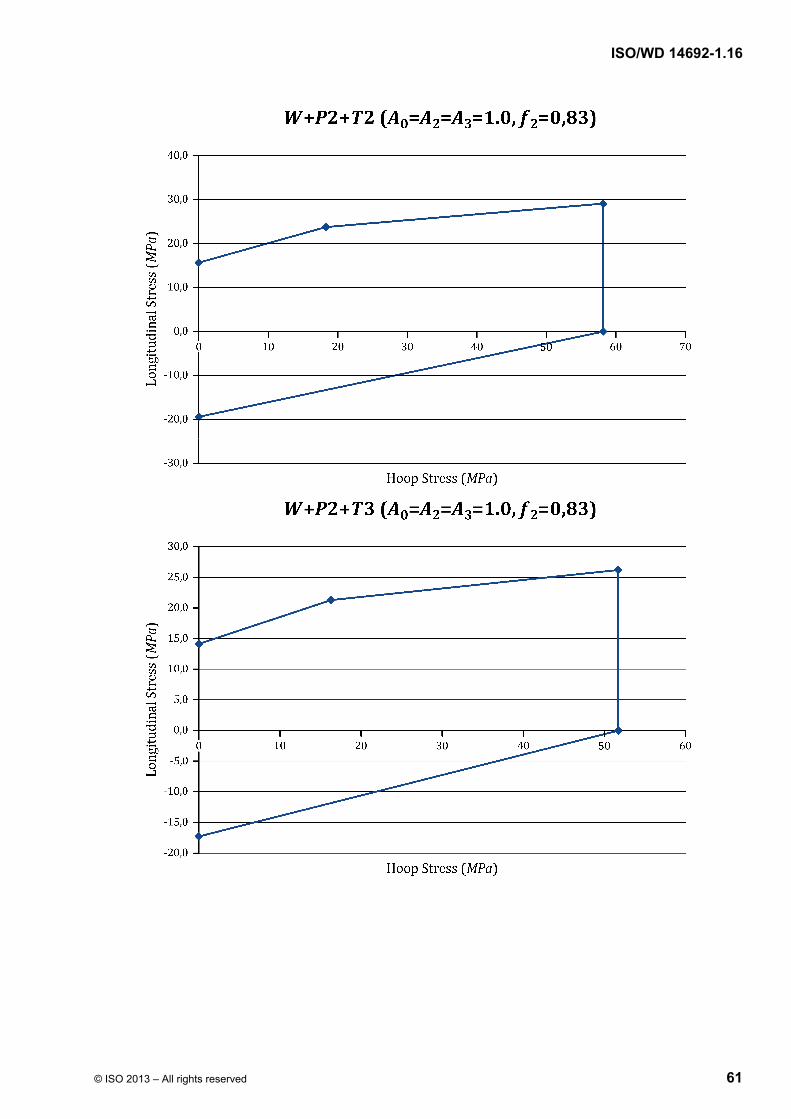
ISO/WD 14692-1.16
© ISO 2013 – All rights reserved 61
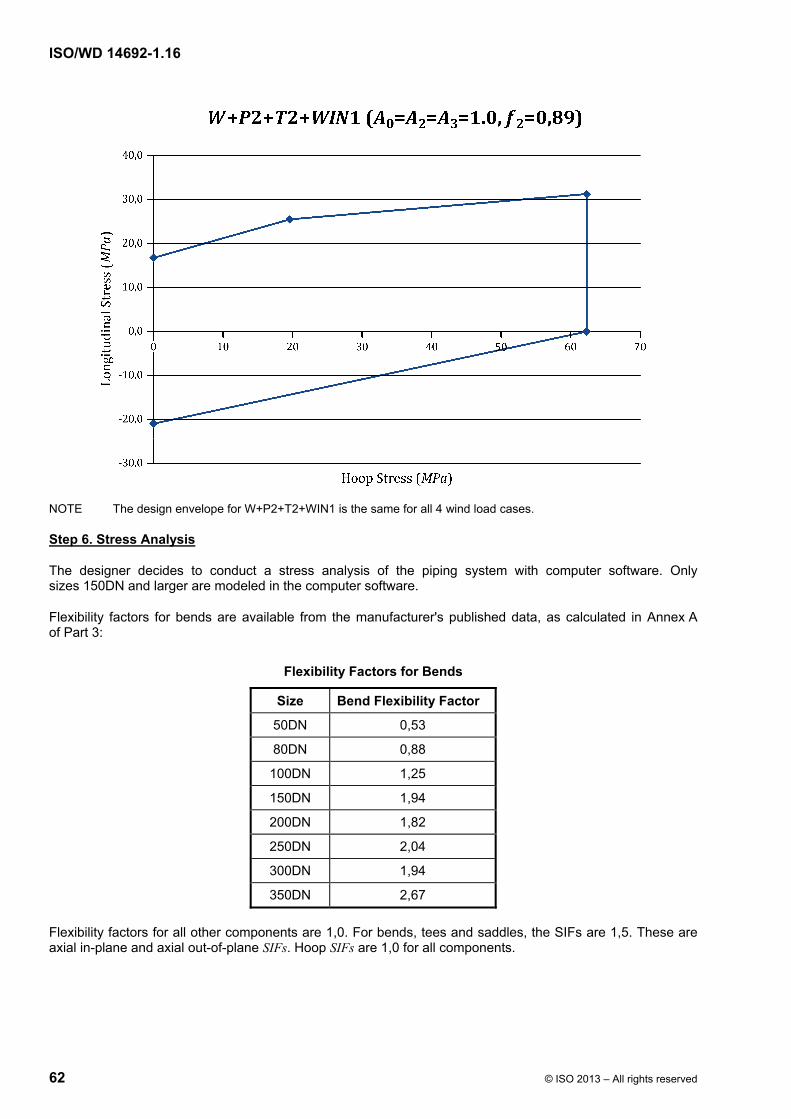
ISO/WD 14692-1.16
62 © ISO 2013 – All rights reserved
NOTE The design envelope for W+P2+T2+WIN1 is the same for all 4 wind load cases.
Step 6. Stress Analysis
The designer decides to conduct a stress analysis of the piping system with computer software. Only sizes 150DN and larger are modeled in the computer software.
Flexibility factors for bends are available from the manufacturer's published data, as calculated in Annex A of Part 3:
Flexibility Factors for Bends
Size Bend Flexibility Factor
50DN 0,53
80DN 0,88
100DN 1,25
150DN 1,94
200DN 1,82
250DN 2,04
300DN 1,94
350DN 2,67
Flexibility factors for all other components are 1,0. For bends, tees and saddles, the SIFs are 1,5. These are axial in-plane and axial out-of-plane SIFs. Hoop SIFs are 1,0 for all components.
ISO/WD 14692-1.16
© ISO 2013 – All rights reserved 63
Since the fittings and the pipe have the same MPRxx rating, the stress analysis calculations use the tr,min values for the pipe, not the fittings. See Annex A from Part 3. However, if the fittings and pipe have different MPRxx values, the fitting is modeled with the values for tr,min for a pipe of the same MPRxx as the fitting (e.g. if 3,0 MPRxx pipe was used with 4,0 MPRxx fittings, then the fittings would be modeled with the tr,min of the 4,0 bar pipe).
Hoop stresses are calculated in accordance with equations 12 and 13 of Part 3. Equation 14 is not used since the system is not a buried system.
Axial stresses are calculated in accordance with equations 15 thru 19 and 21 of Part 3. Equation 20 is not used since this equation is applicable to pipelines, both buried and aboveground, where roping may occur.
With the computer software, the designer plots the hoop and axial stress results on a graph to ensure that the results fall within the design envelope for each particular load case.
External pressure is calculated according to equation 23 of Part 3. Calculations are done as the elastic properties change according to temperature:
External Collapse Pressure in MPa
Size –10 °C 21 °C 50 °C 65 °C
50DN 3,81 3,81 3,73 3,44
80DN 1,24 1,24 1,21 1,12
100DN 0,55 0,55 0,54 0,49
150DN 0,33 0,33 0,32 0,29
200DN 0,32 0,32 0,31 0,29
250DN 0,31 0,31 0,31 0,28
300DN 0,32 0,32 0,31 0,29
350DN 0,31 0,31 0,31 0,28
In all cases, the results are greater than the required design value of 0,1 MPa.
Even though the axial elastic buckling stress is primarily an issue for thin-walled large diameter pipes, it is calculated according to equations 24 thru 26 of Part 3:
Axial Elastic Buckling Stress in MPa
Size Β –10 °C 21 °C 50 °C 65 °C
50DN 1,85 1 192,1 1 192,1 1 156,3 1 096,7
80DN 1,71 757,1 757,1 734,4 696,6
100DN 1,60 539,7 539,7 523,5 496,5
150DN 1,53 433,6 433,6 420,6 398,9
200DN 1,52 429,2 429,2 416,3 394,8
250DN 1,52 426,5 426,5 413,7 392,3
300DN 1,52 430,0 430,0 417,1 395,6
350DN 1,52 427,7 427,7 414,8 393,5
400DN 1,52 430,2 430,2 417,3 395,7
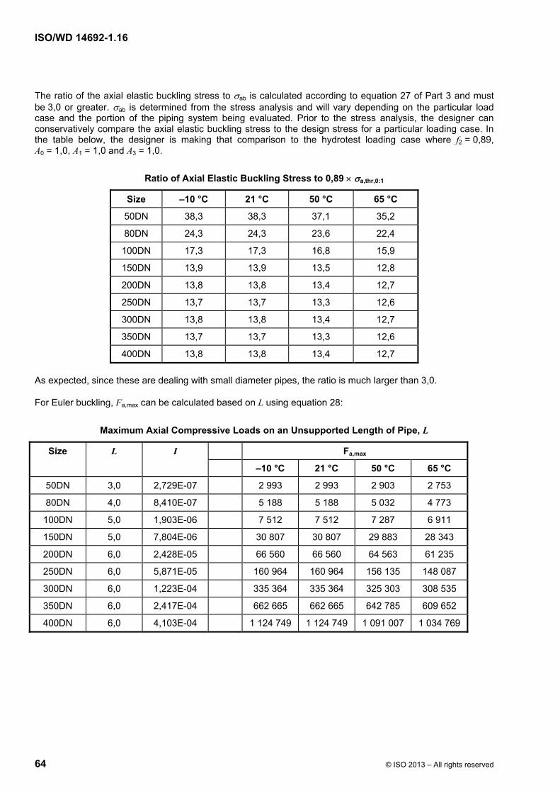
ISO/WD 14692-1.16
64 © ISO 2013 – All rights reserved
The ratio of the axial elastic buckling stress to ab is calculated according to equation 27 of Part 3 and must be 3,0 or greater. ab is determined from the stress analysis and will vary depending on the particular load case and the portion of the piping system being evaluated. Prior to the stress analysis, the designer can conservatively compare the axial elastic buckling stress to the design stress for a particular loading case. In the table below, the designer is making that comparison to the hydrotest loading case where f2 = 0,89, A0 = 1,0, A1 = 1,0 and A3 = 1,0.
Ratio of Axial Elastic Buckling Stress to 0,89 a,thr,0:1
Size –10 °C 21 °C 50 °C 65 °C
50DN 38,3 38,3 37,1 35,2
80DN 24,3 24,3 23,6 22,4
100DN 17,3 17,3 16,8 15,9
150DN 13,9 13,9 13,5 12,8
200DN 13,8 13,8 13,4 12,7
250DN 13,7 13,7 13,3 12,6
300DN 13,8 13,8 13,4 12,7
350DN 13,7 13,7 13,3 12,6
400DN 13,8 13,8 13,4 12,7
As expected, since these are dealing with small diameter pipes, the ratio is much larger than 3,0.
For Euler buckling, Fa,max can be calculated based on L using equation 28:
Maximum Axial Compressive Loads on an Unsupported Length of Pipe, L
Size L I Fa,max
–10 °C 21 °C 50 °C 65 °C
50DN 3,0 2,729E-07 2 993 2 993 2 903 2 753
80DN 4,0 8,410E-07 5 188 5 188 5 032 4 773
100DN 5,0 1,903E-06 7 512 7 512 7 287 6 911
150DN 5,0 7,804E-06 30 807 30 807 29 883 28 343
200DN 6,0 2,428E-05 66 560 66 560 64 563 61 235
250DN 6,0 5,871E-05 160 964 160 964 156 135 148 087
300DN 6,0 1,223E-04 335 364 335 364 325 303 308 535
350DN 6,0 2,417E-04 662 665 662 665 642 785 609 652
400DN 6,0 4,103E-04 1 124 749 1 124 749 1 091 007 1 034 769
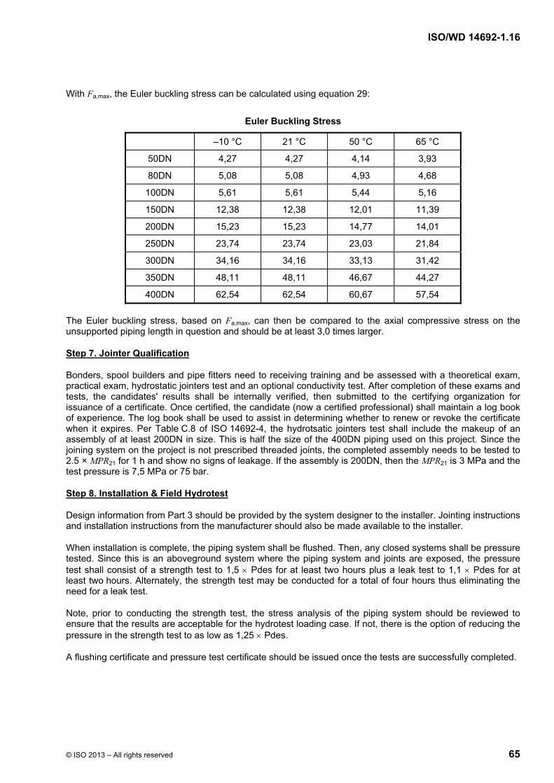
ISO/WD 14692-1.16
© ISO 2013 – All rights reserved 65
With Fa,max, the Euler buckling stress can be calculated using equation 29:
Euler Buckling Stress
–10 °C 21 °C 50 °C 65 °C
50DN 4,27 4,27 4,14 3,93
80DN 5,08 5,08 4,93 4,68
100DN 5,61 5,61 5,44 5,16
150DN 12,38 12,38 12,01 11,39
200DN 15,23 15,23 14,77 14,01
250DN 23,74 23,74 23,03 21,84
300DN 34,16 34,16 33,13 31,42
350DN 48,11 48,11 46,67 44,27
400DN 62,54 62,54 60,67 57,54
The Euler buckling stress, based on Fa,max, can then be compared to the axial compressive stress on the unsupported piping length in question and should be at least 3,0 times larger.
Step 7. Jointer Qualification
Bonders, spool builders and pipe fitters need to receiving training and be assessed with a theoretical exam, practical exam, hydrostatic jointers test and an optional conductivity test. After completion of these exams and tests, the candidates' results shall be internally verified, then submitted to the certifying organization for issuance of a certificate. Once certified, the candidate (now a certified professional) shall maintain a log book of experience. The log book shall be used to assist in determining whether to renew or revoke the certificate when it expires. Per Table C.8 of ISO 14692-4, the hydrotsatic jointers test shall include the makeup of an assembly of at least 200DN in size. This is half the size of the 400DN piping used on this project. Since the joining system on the project is not prescribed threaded joints, the completed assembly needs to be tested to 2.5 × MPR21 for 1 h and show no signs of leakage. If the assembly is 200DN, then the MPR21 is 3 MPa and the test pressure is 7,5 MPa or 75 bar.
Step 8. Installation & Field Hydrotest
Design information from Part 3 should be provided by the system designer to the installer. Jointing instructions and installation instructions from the manufacturer should also be made available to the installer.
When installation is complete, the piping system shall be flushed. Then, any closed systems shall be pressure tested. Since this is an aboveground system where the piping system and joints are exposed, the pressure test shall consist of a strength test to 1,5 Pdes for at least two hours plus a leak test to 1,1 Pdes for at least two hours. Alternately, the strength test may be conducted for a total of four hours thus eliminating the need for a leak test.
Note, prior to conducting the strength test, the stress analysis of the piping system should be reviewed to ensure that the results are acceptable for the hydrotest loading case. If not, there is the option of reducing the pressure in the strength test to as low as 1,25 Pdes.
A flushing certificate and pressure test certificate should be issued once the tests are successfully completed.

ISO/WD 14692-1.16
66 © ISO 2013 – All rights reserved
Bibliography
[1] ISO 14692-2:####, Petroleum and natural gas industries — Glass-reinforced plastics (GRP) piping — Part 2: Qualification and manufacture
[2] ISO 14692-3:####, Petroleum and natural gas industries — Glass-reinforced plastics (GRP) piping — Part 3: System design
[3] ISO 14692-4:####, Petroleum and natural gas industries — Glass-reinforced plastics (GRP) piping — Part 4: Fabrication, installation, inspection and maintenance


