Commercial and Residential Sanitary Sewer System … · Final Commercial and Residential Sanitary...
80
Final Commercial and Residential Sanitary Sewer System Design and Construction Manual Prepared for Jefferson County, Alabama Environmental Services Department November 2015
Transcript of Commercial and Residential Sanitary Sewer System … · Final Commercial and Residential Sanitary...

F i na l
Commercial and Residential Sanitary Sewer System Design and
Construction Manual
Prepared for
Jefferson County, Alabama Environmental Services Department
November 2015
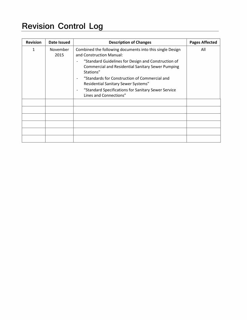
Revision Control Log
Revision Date Issued Description of Changes Pages Affected
1 November 2015
Combined the following documents into this single Design and Construction Manual: - “Standard Guidelines for Design and Construction of
Commercial and Residential Sanitary Sewer Pumping Stations”
- “Standards for Construction of Commercial and Residential Sanitary Sewer Systems”
- “Standard Specifications for Sanitary Sewer Service Lines and Connections”
All

Contents Section Page
1 General Information ................................................................................................................. 1-1 1.1 Purpose .................................................................................................................................. 1-1 1.2 Applicability and Jurisdiction ................................................................................................. 1-1 1.3 Interpretation and Disputes .................................................................................................. 1-2 1.4 Amendments.......................................................................................................................... 1-2 1.5 Contact Information............................................................................................................... 1-2 1.6 Additional Publications .......................................................................................................... 1-2 1.7 Manual Format ...................................................................................................................... 1-3 1.8 Abbreviations and Glossary ................................................................................................... 1-3
2 Permitting ................................................................................................................................ 2-1 2.1 Permits ................................................................................................................................... 2-1
2.1.1 Sewer Connection and Impact .................................................................................. 2-1 2.1.2 Disconnection ........................................................................................................... 2-4 2.1.3 Permit Application Process ....................................................................................... 2-4
2.2 Permit Fees ............................................................................................................................ 2-4 2.3 Time Limit of Permit, Conditions, and Refunds ..................................................................... 2-4
2.3.1 Sewer Impact Permit ................................................................................................ 2-4 2.3.2 Sewer Connection, Repair, or Disconnection Permit ............................................... 2-5 2.3.3 Revocation of Permits ............................................................................................... 2-5
2.4 Additional Permits Required .................................................................................................. 2-5 2.4.1 Alabama Department of Transportation .................................................................. 2-5 2.4.2 Railway ...................................................................................................................... 2-5 2.4.3 Existing Utility ROW .................................................................................................. 2-6 2.4.4 Construction Stormwater Permit ............................................................................. 2-6
2.5 Assurance of Performance ..................................................................................................... 2-6 2.6 Food Service ........................................................................................................................... 2-6 2.7 Disposal of Waste Matter Other than Domestic ................................................................... 2-6 2.8 Document .............................................................................................................................. 2-7
3 System Design – Common Requirements ................................................................................... 3-1 3.1 General ................................................................................................................................... 3-1
3.1.1 Sewer Availability ...................................................................................................... 3-1 3.1.2 Wastewater Quantities ............................................................................................. 3-1 3.1.3 Capacity Analysis ....................................................................................................... 3-2
3.2 Gravity System, Pump Station and Force Main, and Low-Pressure Sewer Systems ............. 3-3 3.3 Standards ............................................................................................................................... 3-3
3.3.1 General...................................................................................................................... 3-3 3.3.2 Materials of Construction, Products, and Equipment .............................................. 3-3 3.3.3 Deviations ................................................................................................................. 3-4
3.4 Calculations, Drawings, and Specifications ............................................................................ 3-4 3.4.1 Calculations ............................................................................................................... 3-4 3.4.2 Drawings ................................................................................................................... 3-4
3.5 Project Submission, Review, and Approval Process .............................................................. 3-7 3.6 Deposits ................................................................................................................................. 3-8
3.6.1 As Constructed Drawings for Main Sewers, Pump Stations, and Force Mains ........ 3-8 3.7 Standard Drawings and Documents ...................................................................................... 3-8
COMMERCIAL-RESIDENTIALSANITARYSEWERSYSTEMDESIGNANDCONSTRUCTIONMANUAL.DOCX III WBG051214112523BHM

CONTENTS, CONT.
3.7.1 Standard Drawings .................................................................................................... 3-8
4 Construction and Closeout ........................................................................................................ 4-1 4.1 Contractor Qualifications ....................................................................................................... 4-1 4.2 Submittals ............................................................................................................................... 4-1 4.3 Start of Construction Notification .......................................................................................... 4-1 4.4 Inspection and Final Project Acceptance ............................................................................... 4-1 4.5 New Easements and Deeds .................................................................................................... 4-2 4.6 Vacating Existing Easement for Construction/Site Improvements ........................................ 4-3 4.7 As-Constructed (Record) Drawings and Other Closeout Documentation .............................. 4-4
4.7.1 As-Constructed (Record) Drawing Standards and Requirements ............................. 4-4 4.7.2 Closed-Circuit Television ........................................................................................... 4-5 4.7.3 Testing Reports .......................................................................................................... 4-5 4.7.4 Equipment Warranties, Operation and Maintenance Manuals ................................ 4-5
4.8 Final Project Acceptance ........................................................................................................ 4-5 4.9 Documents ............................................................................................................................. 4-6
5 Service Lines ............................................................................................................................. 5-1 5.1 General Requirements ........................................................................................................... 5-1 5.2 Design ..................................................................................................................................... 5-2
5.2.1 General ...................................................................................................................... 5-2 5.2.2 Size and Materials ..................................................................................................... 5-3 5.2.3 Diameter and Slope ................................................................................................... 5-3 5.2.4 Main Sewer Connections ........................................................................................... 5-3 5.2.5 Manholes ................................................................................................................... 5-4 5.2.6 Connection Riser ....................................................................................................... 5-4 5.2.7 Force Main ................................................................................................................. 5-4 5.2.8 Standard Drawings and Specifications ...................................................................... 5-4
5.3 Plumbing Contractor .............................................................................................................. 5-5 5.4 Inspection and Testing ........................................................................................................... 5-6 5.5 Miscellaneous ......................................................................................................................... 5-6
5.5.1 Grease Control........................................................................................................... 5-6 5.5.2 Oil Separators/Removal Devices ............................................................................... 5-6 5.5.3 Septic Tank Conversion ............................................................................................. 5-6 5.5.4 Garbage Dumpster Drains and Garbage Can Washing Pads ..................................... 5-6
5.6 Sewer Service Line Replacement and Rehabilitation ............................................................. 5-7 5.6.1 Replacement ............................................................................................................. 5-7 5.6.2 Rehabilitation ............................................................................................................ 5-7
5.7 Disconnection for Building Demolition .................................................................................. 5-7
6 Main Sewers ............................................................................................................................. 6-1 6.1 General Requirements ........................................................................................................... 6-1 6.2 Design ..................................................................................................................................... 6-2
6.2.1 Size and Materials ..................................................................................................... 6-2 6.2.2 Main Sewer Location and Layout .............................................................................. 6-2 6.2.3 Easement ................................................................................................................... 6-4 6.2.4 Wastewater Quantities ............................................................................................. 6-5 6.2.5 Hydraulic Calculations ............................................................................................... 6-5 6.2.6 Velocity and Slope ..................................................................................................... 6-5 6.2.7 Finished Floor Elevation ............................................................................................ 6-5 6.2.8 Manholes ................................................................................................................... 6-6 6.2.9 Standard Drawings and Specifications ...................................................................... 6-7
IV COMMERCIAL-RESIDENTIALSANITARYSEWERSYSTEMDESIGNANDCONSTRUCTIONMANUAL.DOCX WBG051214112523BHM

CONTENTS, CONT.
6.3 Road Bores/Trenchless Crossings, and Casing ....................................................................... 6-7 6.4 Construction and Testing Sequencing ................................................................................... 6-8 6.5 Inspection and Testing ........................................................................................................... 6-8
7 Pump Stations and Force Mains................................................................................................. 7-1 7.1 General Requirements ........................................................................................................... 7-1 7.2 Design .................................................................................................................................... 7-2
7.2.1 Pump Station Location and Layout ........................................................................... 7-2 7.2.2 Easements and Deeds ............................................................................................... 7-3 7.2.3 Wastewater Quantities ............................................................................................. 7-3 7.2.4 Reports ...................................................................................................................... 7-3 7.2.5 Standard Drawings and Specifications ...................................................................... 7-5
7.3 Pump Station ......................................................................................................................... 7-6 7.3.1 Pump Station Classifications ..................................................................................... 7-6 7.3.2 Pumps ....................................................................................................................... 7-6 7.3.3 Standby Pumps and Generator ................................................................................. 7-8 7.3.4 Valves ........................................................................................................................ 7-9 7.3.5 Site Security ............................................................................................................ 7-10 7.3.6 Exposed Pipe and Valve Freeze Protection............................................................. 7-10 7.3.7 Access Road and Area within Fencing .................................................................... 7-10 7.3.8 Water Service .......................................................................................................... 7-10 7.3.9 Electrical .................................................................................................................. 7-10 7.3.10 Controls ................................................................................................................... 7-11 7.3.11 Structural ................................................................................................................ 7-14 7.3.12 Bypass Pumping ...................................................................................................... 7-15
7.4 Force Main ........................................................................................................................... 7-15 7.5 Inspection and Testing ......................................................................................................... 7-16 7.6 Operations and Maintenance Manual ................................................................................. 7-16 7.7 Asset Registry ....................................................................................................................... 7-16
8 Low-Pressure Sewer System ...................................................................................................... 8-1 8.1 Ownership .............................................................................................................................. 8-1 8.2 General Requirements ........................................................................................................... 8-2
8.2.1 Pump Station Location, Layout ................................................................................. 8-2 8.2.2 Easements and Property ........................................................................................... 8-3 8.2.3 Wastewater Quantities ............................................................................................. 8-4 8.2.4 Reports ...................................................................................................................... 8-4 8.2.5 Standard Drawings and Specifications ...................................................................... 8-5
8.3 Design Resources and References ......................................................................................... 8-6 8.4 Force Main ............................................................................................................................. 8-6
8.4.1 Sizing ......................................................................................................................... 8-6 8.4.2 Material of Construction ........................................................................................... 8-7 8.4.3 Installation ................................................................................................................ 8-7 8.4.4 Valves ........................................................................................................................ 8-7 8.4.5 LPSS Pump Stations ................................................................................................... 8-8 8.4.6 Inspection ............................................................................................................... 8-10 8.4.7 Startup and Testing ................................................................................................. 8-10 8.4.8 Operations and Maintenance ................................................................................. 8-11
COMMERCIAL-RESIDENTIALSANITARYSEWERSYSTEMDESIGNANDCONSTRUCTIONMANUAL.DOCX V WBG051214112523BHM

CONTENTS, CONT.
Appendix
1 Abbreviations and Glossary 2 Permitting 3 System Design – Common Requirements 4 Construction and Closeout 5 Service Lines 6 Main Sewers 7 Pump Stations and Force Mains 8 Low-Pressure Sewer System
Table Page
2-1 Permit Requirements .......................................................................................................................... 2-3
3-1 Base Flow Rates Based Upon Type of Facility/Structure ..................................................................... 3-1
6-1 Minimum Sanitary Sewer Slopes for Sanitary Sewer Mains ............................................................... 6-5
Figure
2-1 Permitting and Construction General Process Flow for New Commercial and Residential Connections and Developments ....................................................................................... 2-2
VI COMMERCIAL-RESIDENTIALSANITARYSEWERSYSTEMDESIGNANDCONSTRUCTIONMANUAL.DOCX WBG051214112523BHM

SECTION 1
General Information
1.1 Purpose This Commercial and Residential Sanitary Sewer System Design and Construction Manual (referenced throughout as the “Manual”) details the requirements established by the Jefferson County Environmental Services Department (ESD) for design and construction of commercial and residential sanitary sewer systems. This Manual has been prepared to provide an understanding of the requirements of the ESD Department and to assist in providing the basis for consistent design standards and policies. It sets forth requirements that should be followed to expedite the approval of projects. Also, the Manual addresses the protection of the public health, safety, and welfare by focusing on sound design and construction requirements.
Sanitary sewer system components included in this Manual are sanitary sewer service lines, connections, gravity sewers, force mains, pump stations, and low-pressure sewer systems. The purpose of these requirements is to provide uniform design and construction standards, in addition to establishing a minimum allowed level of quality and performance for commercial and residential sanitary sewer systems. The system components shall be designed and constructed in such a manner to minimize infiltration and inflow (I/I) and to ensure that these added components do not create long-term maintenance problems for ESD. The end result should be public infrastructure that is cost-effective and maintainable by the ESD in the long term.
1.2 Applicability and Jurisdiction This Manual identifies a single set of standards, submittal, and approval procedures to be used in the planning, permitting, design, and construction of commercial and residential sanitary sewer projects within the ESD service area. This Manual is not intended to serve as a step-by-step design methodology guide, nor does this Manual address every situation that may arise. The application of sound engineering/surveying/ construction principles and judgment combined with the information contained herein are necessary to complete the planning, permitting, design, and construction of commercial and residential sanitary sewer system projects. In addition, other Jefferson County departments, as well as state and federal agencies, may have requirements other than those contained herein that must be addressed to obtain approval.
The Manual is primarily intended for use by Owners and Engineers who construct or modify sanitary sewer components as additions or modifications to the System at the Owner’s full or partial cost for eventual acceptance for ownership and maintenance by the County. While County-funded public works projects are intended to be generally consistent with this Manual, they may differ in some material aspects at ESD’s discretion.
The design of the proposed system must be reviewed and approved by the ESD prior to permitting, bidding, and/or construction. Construction and testing are subject to inspection by the ESD to ensure compliance with the design. Approval of the proposed system by the ESD shall not relieve the plumber/designer/ engineer (as applicable) or plumber/construction contractor from compliance with provisions of this Manual unless a written variance is received from ESD. Constructed facilities that deviate from the design without approval of ESD or that fail the testing requirements may be rejected and shall not be allowed to discharge to ESD’s system until compliance is achieved. Achieving compliance may include, but not be limited to:
• Preparation and submission of a revised design to the ESD for review and approval.
• Replacement or components that do not comply with the approved design and the requirements of this Manual.
• Reinstallation of components in a manner (bedding, backfill, slope, etc.) that complies with the approved design and this Manual.
COMMERCIAL-RESIDENTIALSANITARYSEWERSYSTEMDESIGNANDCONSTRUCTIONMANUAL.DOCX 1-1 WBG051214112523BHM

SECTION 1—GENERAL INFORMATION
1.3 Interpretation and Disputes The Director of Environmental Services shall be responsible for the interpretation and application of the Manual. In those cases where significant ambiguity exists or a dispute arises in the Manual’s interpretation or application, the Deputy County Manager for Infrastructure or, in his/her absence, the County Manager’s designee shall render a decision at his/her sole discretion.
1.4 Amendments This Manual is intended to be a dynamic document. As design and construction criteria and technology evolve, the Manual will require revisions and improvements. It is therefore recommended that prior to the start of a project, consultants contact ESD to verify that the designer is using the latest version of the requirements and the associated details and specifications.
1.5 Contact Information The address for ESD is: Environmental Services Department Jefferson County Court House 716 Richard Arrington Jr. Blvd North Suite A 300 Birmingham, AL 35203
The following list provides contact information for applicable offices within the ESD:
• Capacity Analysis and Sewer Availability − Phone (205) 325-1445
• Food Service Applicants, Grease Control and Industrial Compliance − Phone: (205) 238-3876, (205) 238-3878, or (205) 238-3866
• General Information and Environmental Service Administration − Phone: (205) 325-5496
• Service Lines - Plan Reviews, Permits, and Inspections − Phone: (205) 325-5231
• Line Location − Fax (205) 325-5698; email [email protected]
• Right of Way Permit Application − Phone: (205) 521-7515
• Main Sewer, Pump Stations Plan Reviews, Permits and Inspections − Phone: (205) 521-7515
Additional information can be found on the ESD’s web site http://www.jeffcoes.org.
1.6 Additional Publications Listed below are publications referenced in these commercial and residential sewer system design requirements. The designer should ensure that the most recent versions are being used for design and construction.
• Jefferson County Sewer Use Administrative Ordinance (www.jeffcoes.org)
• Jefferson County Sewer Charge Ordinance (www.jeffcoes.org)
• Jefferson County Department of Health: On Site Sewage Disposal Regulations (www.jcdh.org/EH/CEP/CEP08.aspx)
• Recommended Standards for Wastewater Facilities published by Health Education Services, a division of Health Research, Inc. (commonly referred to as the 10-State Standards) (www.10statesstandards.com)
1-2 COMMERCIAL-RESIDENTIALSANITARYSEWERSYSTEMDESIGNANDCONSTRUCTIONMANUAL.DOCX WBG051214112523BHM

SECTION 1—GENERAL INFORMATION
The standards, design, and construction recommendations and requirements within this Manual do not override the Sewer Use Administrative Ordinance approved by the County, separately bid County-funded public works projects, or other state or federal regulatory requirements.
1.7 Manual Format Sections 1 through 4 of this Manual include general information along with permitting, design, construction, and close-out requirements. Sections 5, 6, and 7 address the design of Main Sewers, Service Lines, Pump Stations and Force Mains, respectively. Section 8 addresses Low Pressure Sewer Systems. Appendices are organized as follows:
• Appendix 1 Abbreviations and Glossary • Appendix 2 Permitting • Appendix 3 System Design – Common Requirements • Appendix 4 Construction and Closeout • Appendix 5 Service Lines • Appendix 6 Main Sewers • Appendix 7 Pump Stations and Force Mains • Appendix 8 Low-Pressure Sewer System
1.8 Abbreviations and Glossary Appendix 1 includes a series of abbreviations and a glossary of terms that are used throughout this manual.
COMMERCIAL-RESIDENTIALSANITARYSEWERSYSTEMDESIGNANDCONSTRUCTIONMANUAL.DOCX 1-3 WBG051214112523BHM


SECTION 2
Permitting
2.1 Permits Permits are required by the ESD to ensure that proper requirements, conditions, and standards are used in design and construction and to assist ESD staff in the monitoring of progress and assurance of quality in the constructed projects. Permits or approved plans from ESD are specifically required for:
• Construction of a new sewer service line (lateral)
• Repairs to existing sewer service line and/or connection
• Connection of a service line to the sanitary sewer system
• Construction of a main sewer
• Construction of a pump station and its associated force main
• Disconnection of a sewer service line
• Any plumbing change to a building presently connected to the sewer system that impacts discharge (volume or wastewater characteristics)
• Significant site or construction work performed within a County sanitary sewer easement
• This is applicable for all the ESD service areas including both incorporated and unincorporated areas of Jefferson County and all municipalities served by the ESD. Each permit required is discussed in the following subsections. The discussion of each permit is not meant to provide all information regarding that particular permit. The applicant should refer to the appropriate regulation, ordinance, or code that will describe the permit requirements in more detail. It also is important to note that performing any work without the required and appropriate permit may result in a stop work order and additional fees.
Figure 2-1 provides a general process flow diagram for permitting through construction.
2.1.1 Sewer Connection and Impact The permits issued by the ESD relating to sewer connections include:
1. Sewer Impact 2. Sewer Connection/Disconnection 3. Repair 4. Tap 5. Lateral Extension
The first two permits are required for any new connections to the sanitary sewer system. Only the sewer impact permit is required if the property is already connected to the sewer and all work being performed is limited to the addition or removal of plumbing fixtures or restaurant equipment and/or seating where no work is required on the existing service line and no additional service line(s) are required.
A Sewer Impact Permit is required to be obtained prior to issuance of a building permit.
COMMERCIAL-RESIDENTIALSANITARYSEWERSYSTEMDESIGNANDCONSTRUCTIONMANUAL.DOCX 2-1 WBG051214112523BHM

SECTION 2—PERMITTING
FIGURE 2-1 Permitting and Construction General Process Flow for New Commercial and Residential Connections and Developments
Table 2-1 further expands and details the permit requirements associated with the type of connection.
Is Existing Main Sewer Available?
(Section 3.1.1)
Yes
No
Is volume of Sanitary Sewer Flow Less Then
2,500 gpd?
Yes
No
Complete and Submit Capacity Analysis Review Project Fact Sheet Form
Begin Construction
Obtain Building Permit (Note that this permit is provided by agency(s) other than the ESD)
Is this a Food Service Industry
No
Yes
Comply with Requirements of the Grease Control Program
(Section 2.6) and Submit Utility Plans for Review and Approval
Obtain Impact Permit
(Section 2.3)
Main Sewer (Section 6)
Pump Stations and Force Mains (Section 7)
Service Lines (Section 5)
Complete Required Inspections by the ESD. .
Complete Required Inspections by the ESD. Correct any
Deficiencies.
Complete Required Startup and Testing and Inspections by the ESD. Correct any Deficiencies.
Obtain Connection Permit
Provide As Constructed Drawings and Deeds of
Correction
ESD Accepts Sewer Main, Pump Station and Force Main as
Applicable
Request Return of Deposit(s)
ESD Activates Sewer Billing
Is Capacity is Available?
(Section 3.1.2)
Design, Approval and Permitting of Main Sewer, Pump Station and
Force Main or Low-Pressure Sewer System (Section 6, 7 or 8
Respectively)
Low-Pressure Sewer System(Section 8)
2-2 COMMERCIAL-RESIDENTIALSANITARYSEWERSYSTEMDESIGNANDCONSTRUCTIONMANUAL.DOCX WBG051214112523BHM

SECTION 2—PERMITTING
TABLE 2-1 Permit Requirements
Permit Required
Item # Description Sewer Impact Sewer Connection Comment
1 Buildings that do not/will not contain any internal plumbing, plumbing fixtures, or stubouts
No No No permit required for issuance of building permit.
2 Building contains plumbing, plumbing fixtures, or stubouts; sanitary sewer is not available to service the building; and the Owner has applied for a permit for a septic tank from the Jefferson County Department of Health
No No No permit required for issuance of a building permit.
3 Building contains plumbing, plumbing fixtures, or stubouts, sanitary sewer is available to service the building and the Owner has not applied for a permit for a septic tank from the Jefferson County Department of Health
Yes Yes Impact Permit required prior to issuance of a building permit.
4 Existing building or home is presently on a septic tank system and the Owner desires connection to the sewer system
Yes Yes Septic tank conversion Impact Permit required prior to issuance of a building permit.
5 An existing building or home is presently connected to the ESD sewer system and the Owner is installing additional fixtures that will discharge to the sewer system.
Yes Yes – only if changes to the existing service line are
required. If no changes or additional service lines are required, then permit not
required.
Impact permit required prior to issuance of a building permit.
6 A restaurant or lounge presently connected to the sewer system is adding seats.
Yes Consult ESD Impact permit required prior to issuance of a building permit.
7 A restaurant or lounge is added to a building presently connected to the sewer system
Yes Yes – only if changes to the existing service line are
required. If no changes or additional service lines are required, then permit not
required
Impact permit required prior to issuance of a building permit.
8 An industry presently connected to the sewer system is adding or changing a process that will increase the volume of flow or change the character of the waste discharged to the sewer system
Yes Yes – only if changes to the existing service line are
required. If no changes or additional service lines are required, then permit not
required
Impact permit required prior to issuance of a building permit.
9 Repair or modification to an existing service line connection is needed or required
Consult ESD Yes Site utility drawings may be required.
10 An existing service line is to be disconnected because of demolition of the associated building
No No Disconnection permit is required. A fixture count is required prior to demolition.
COMMERCIAL-RESIDENTIALSANITARYSEWERSYSTEMDESIGNANDCONSTRUCTIONMANUAL.DOCX 2-3 WBG051214112523BHM

SECTION 2—PERMITTING
2.1.2 Disconnection A permit to disconnect or plug a sewer must be obtained by the owner’s plumber/demolition contractor from the ESD Sewer Permitting and Inspection Office as well as an inspection made by the ESD Sewer Service Inspector at the time of discontinuance. The form for obtaining this permit is available from ESD.
2.1.3 Permit Application Process • Sewer Impact:
− Each application and permit fee shall be filed with the ESD Sewer Permitting and Inspections Office on the appropriate form. These forms are available from ESD and have also been included in Appendix 2.
− The Sewer Impact Permit shall be obtained and signed by the owner or owner’s agent.
− The Sewer Impact Permit shall be obtained prior to commencement of construction of any new building, addition to or remodeling of a building, or installation of a service line to an existing building if the Owner desires connection to the sewer system.
− If any fixtures or stubouts for fixtures are installed prior to a permit being obtained, the permit fee shall be double the amount per fixture as established in the Jefferson County Sewer Use Charge Ordinance.
• Sewer Connection:
− The Sewer Connection Permit shall be obtained prior to starting any excavation for the installation, repair, or disconnection of a service line or connection. These forms are available from the ESD Sewer Permitting and Inspection Office and have also been included in Appendix 2.
− The Sewer Connection Permit shall be obtained by the Owner’s plumber from the ESD Sewer Permitting and Inspections Office.
− The Sewer Connection Permit shall be obtained and signed by a Master Plumber or his duly authorized representative provided that a letter is on file with ESD authorizing that person to be the representative for the firm.
− The plumbing company shall have a current Bond with the Jefferson County Commission, and be licensed by the State of Alabama.
2.2 Permit Fees The appropriate sewer impact and sewer connection, repair, tap, or disconnection fees will be calculated in accordance with the current version of the Jefferson County Sewer Use Charge Ordinance (see the ESD’s web site [http://www.jeffcoes.org] for more details and the fee schedule).
2.3 Time Limit of Permit, Conditions, and Refunds 2.3.1 Sewer Impact Permit 2.3.1.1 Time Limit Valid for a period of 2 years from the date of issuance. The owner must renew the permit after this time limit has expired in order to utilize the permit. There is no charge for renewal of a permit unless the quantity of fixtures has changed from that included in the original permit.
2.3.1.2 Conditions Owners of commercial developments are required to submit site utility drawings for review and approval. In some instances, the ESD may also require the submission of plumbing drawings. Drawings are not required for residential developments.
2-4 COMMERCIAL-RESIDENTIALSANITARYSEWERSYSTEMDESIGNANDCONSTRUCTIONMANUAL.DOCX WBG051214112523BHM

SECTION 2—PERMITTING
To finalize an Impact Permit and prior to obtaining a Certificate of Occupancy, the Owner or plumbing contractor shall make arrangements for the building or home to be open at the time of the inspection to allow the ESD Sewer Service Inspector to count the number of plumbing fixtures indicated on the Sewer Impact Permit. Failure to make such arrangements shall cause future permits to be denied until such arrangements are made.
2.3.1.3 Refund A refund will be calculated in accordance with the current version of the Jefferson County Sewer Use Ordinance where deemed to be applicable.
2.3.2 Sewer Connection, Repair, or Disconnection Permit An issued permit shall be construed to be a license to proceed with the work and is subject to the additional conditions provided in the permit. Permits shall be obtained after completion of the “plumbing rough stage” of a structure and/or after the activation/acceptance of a main sewer/main sewer extension.
The cost of a sewer connection, repair, or disconnection permit is non-refundable.
2.3.3 Revocation of Permits In accordance with the Jefferson County Sewer Use Charge Ordinance and Sewer Use Administrative Ordinance, the ESD may revoke a permit if there has been any false statement or misrepresentation as to a material fact in the application, or in the plans on which the permit is based. The ESD may revoke a permit or approval in the event that any part of the construction of the service line is in violation of, or not in conformity with, the requirements of this Manual and/or the Ordinances.
2.4 Additional Permits Required It is not the responsibility of ESD nor the intent of this Manual to inform each Owner/Developer of all permits that may be required in the area the project is to be performed. The applicant may be required to obtain various permits from railroads, utilities, municipalities, county, state, and federal agencies for a particular project. It is the applicant’s responsibility to determine and obtain any and all permits that may be required for a project.
The following subsections summarize several potential permit requirements. The list of required permits should be detailed within the sewer construction drawings and site utility plans.
2.4.1 Alabama Department of Transportation For any sanitary sewer facilities proposed to be installed within State highway right of way, ALDOT requires a Right of Way Accommodation Permit along with a deposit or bond. The Design Engineer or Owner/ Developer shall provide all required information to the ESD for preparation of the Right of Way Accommodation Permit(s). The ESD will prepare the permit(s) for the Jefferson County Commission to approve and execute. A copy of the information form to allow completion of the Right of Way Accommodation Permit is provided in Appendix 2.
The State requires the County, rather than any private party, or Owner/Developer to submit the application for permit agreements. Accordingly, the project Owner/Developer must enter into an agreement with the County accepting responsibilities imposed by the State. The Owner/Developer is responsible for performing certain duties imposed on the County by the State. The Design Engineer, and/or Owner/Developer, is responsible for the accuracy of all information conveyed on the permit application along with all costs associated with preparation of the Permit and the deposit or bond. Further, the County is not responsible for the State revoking an Accommodation Agreement after it has been issued. Any inquiries concerning this matter should be directed to the Environmental Services Department, Sewer Plans Review Office.
2.4.2 Railway In the event a proposed main sewer or force main is to be located within, or cross, property and/or tracks owned by a railway, the Designer/Engineer or Owner/Developer is responsible for providing all required
COMMERCIAL-RESIDENTIALSANITARYSEWERSYSTEMDESIGNANDCONSTRUCTIONMANUAL.DOCX 2-5 WBG051214112523BHM

SECTION 2—PERMITTING
information and a complete application packet as required by the railway to the ESD. The ESD will contact the railway and submit the documents as part of the process to obtain an agreement. The Designer/ Engineer is responsible for designing the sewer or force main in accordance with the requirements of the railway and the ESD. Costs such as crossing fees and application fees imposed by the railway are to be paid by the Owner/Developer.
2.4.3 Existing Utility ROW In the event a proposed main sewer or force main is to be located within, or cross, property owned by a utility, the Designer/Engineer or Owner/Developer is responsible for providing all required information and a complete application packet as required by the utility to the ESD. The ESD will contact the utility and submit the documents as part of the process to obtain an agreement. The Designer/Engineer is responsible for designing the sewer or force main in accordance with the requirements of the utility and the ESD. Costs such as crossing fees and application fees imposed by the utility are to be paid by the Owner/Developer.
2.4.4 Construction Stormwater Permit For many residential and commercial construction projects that include installation of sewers and pump stations, a General National Pollutant Discharge Elimination System (NPDES) construction stormwater permit is required. The Owner/Developer is responsible for preparation, implementation, and maintenance of the Construction Best Management Practices Plan (CBMPP) and when applicable obtaining a permit from the Alabama Department of Environmental Management (ADEM). All fees associated with the permit along with that for preparation, implementation, and maintenance of the CBMPP are the responsibility of the Owner/Developer.
2.5 Assurance of Performance In certain circumstances, ESD may allow certain alternatives to the standard installation and acceptance procedures in the event construction within a housing development/subdivision will be ongoing and connection to an ESD main sewer is needed for completed structures. This includes situations where installation of other utilities is ongoing. As detailed in Section 6.4, all buried utilities (gas, power, fiber, telephone, etc.) that will cross the sewer along with paving shall be complete prior to final CCTV and leak testing of the main sewer. Completion of this final inspection and testing is required for connection to the ESD system.
This process where construction is ongoing and connection to an ESD main sewer is needed requires the execution of an agreement (Assurance of Performance Agreement) and payment of a surety to allow early connection to the system with the understanding that CCTV and leak testing or other activities will be performed in the future after all other required work is completed. A copy of this agreement is included in Appendix 2.
2.6 Food Service All food service projects having the potential to discharge fats, oils, and grease into the sewer system shall obtain a Grease Control Permit. In addition, the facility must be properly reviewed by the authorizing Department of Health for either Jefferson, Shelby, or St. Clair County. Food service facilities may include, but are not limited to, restaurants, school cafeterias, coffee shops, clubs, bars, or any other premise where items may be served or dispensed for human consumption. For questions related to the permit, the Grease Control Program Coordinator can be contacted through the address and phone number provided in Section 1.4.
2.7 Disposal of Waste Matter Other than Domestic Projects that may include discharges to the sewer that are not consistent with domestic sewage must be reviewed and approved by the Barton Laboratory Division of ESD. Contact numbers for industrial compliance can be found in Section 1.5.
2-6 COMMERCIAL-RESIDENTIALSANITARYSEWERSYSTEMDESIGNANDCONSTRUCTIONMANUAL.DOCX WBG051214112523BHM

SECTION 2—PERMITTING
2.8 Document The following documents are provided as part of Appendix 2 for reference:
• Sewer Impact Form • Sewer Connection Permit • Assurance of Performance Agreement
COMMERCIAL-RESIDENTIALSANITARYSEWERSYSTEMDESIGNANDCONSTRUCTIONMANUAL.DOCX 2-7 WBG051214112523BHM


SECTION 3
System Design – Common Requirements
3.1 General This section of the Manual addresses common requirements related to the design of service lines, main sewers, pump stations, and force mains associated with residential and commercial developments. A complete design, which will include drawings, specifications, and calculations, is required to be prepared for all main sewers, pump stations, and force mains that are to be built in Jefferson County and connected to the ESD’s sewer system. Site utility drawings are required for all service lines associated with all non-single family residential connections. Calculations may be required in certain cases to confirm the capacity.
Any costs attributable to permitting, design, and construction of the sewer system shall be the responsibility of the Owner/Developer (see Section 2). The Professional Engineer (PE), employed by the Owner/Developer, is fully responsible for the design and ensuring compliance with the requirements herein. The Engineer is encouraged to discuss each proposed development with the ESD staff prior to start of design and as the work progresses.
3.1.1 Sewer Availability To connect to the ESD’s sewer system, a main sewer, manhole, or pump station must be available and located on the subject property or within an adjacent public easement or right-of-way and within the extended property lines as illustrated on Standard Drawing No. 3305-340 included in Appendix 3. Sewer service lines and force mains may not extend across adjacent private properties. Any exception or waiver of these requirements must be approved by the ESD.
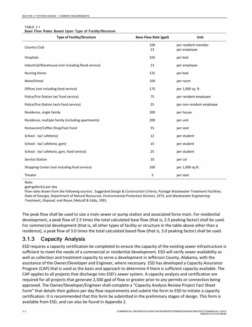
3.1.2 Wastewater Quantities Determining the required main sewer, pump station and associated force main capacity requires consideration of not only the current commercial and/or residential development but potential future growth within the upper reaches of the sewer drainage/ service area as part of the process to develop a long-range plan for sizing and installation of main sewers. The plan must consider the entire drainage area beyond the limits of the subdivision (that is, future development, commercial and residential, must be accounted for in the sizing of the main). A main sewer, pump station, and its associated force main shall be designed to carry the flow from the estimated ultimate tributary population. Table 3-1 provides typical sanitary sewage flow rates by type of facility/structure. These rates shall be used to calculate flow rates unless alternate rates are submitted to and approved by the ESD.
TABLE 3-1 Base Flow Rates Based Upon Type of Facility/Structure
Type of Facility/Structure Base Flow Rate (gpd) Unit
Bar, Tavern 3 13
per customer
per employee
Barber Shop/Beauty Salon 333 per chair
Church (not including food service or day schools) 5 per seat
Coffee Shop 6 10
per customer per employee
Coin Laundries 400 per machine
Commercial Laundries 550 per machine
Commercial/Mercantile Building 75 per 1000 sq. ft.
COMMERCIAL-RESIDENTIALSANITARYSEWERSYSTEMDESIGNANDCONSTRUCTIONMANUAL.DOCX 3-1 WBG051214112523BHM
SECTION 3—SYSTEM DESIGN – COMMON REQUIREMENTS
TABLE 3-1 Base Flow Rates Based Upon Type of Facility/Structure
Type of Facility/Structure Base Flow Rate (gpd) Unit
Country Club 100 13
per resident member per employee
Hospitals 165 per bed
Industrial/Warehouse (not including flood service) 13 per employee
Nursing Home 125 per bed
Motel/Hotel 100 per room
Offices (not including food service) 175 per 1,000 sq. ft.
Police/Fire Station (w/ food service) 75 per resident employee
Police/Fire Station (w/o food service) 25 per non-resident employee
Residence, single family 200 per house
Residence, multiple family (including apartments) 200 per unit
Restaurant/Coffee Shop/Fast Food 55 per seat
School - (w/ cafeteria) 12 per student
School - (w/ cafeteria, gym) 15 per student
School - (w/ cafeteria, gym, food service) 25 per student
Service Station 10 per car
Shopping Center (not including food service) 100 per 1,000 sq.ft.
Theater 3 per seat
Note: gpd=gallon(s) per day Flow rates drawn from the following sources: Suggested Design & Construction Criteria, Package Wastewater Treatment Facilities; State of Georgia, Department of Natural Resources, Environmental Protection Division, 1973, and Wastewater Engineering: Treatment, Disposal, and Reuse; Metcalf & Eddy, 1991.
The peak flow shall be used to size a main sewer or pump station and associated force main. For residential development, a peak flow of 2.5 times the total calculated base flow (that is, 2.5 peaking factor) shall be used. For commercial development (that is, all other types of facility or structure in the table above other than a residence), a peak flow of 3.0 times the total calculated based flow (that is, 3.0 peaking factor) shall be used.
3.1.3 Capacity Analysis ESD requires a capacity certification be completed to ensure the capacity of the existing sewer infrastructure is sufficient to meet the needs of a commercial or residential development. ESD will verify sewer availability as well as collection and treatment capacity to serve a development in Jefferson County, Alabama, with the assistance of the Owner/Developer and Engineer, where necessary. ESD has developed a Capacity Assurance Program (CAP) that is used as the basis and approach to determine if there is sufficient capacity available. The CAP applies to all projects that discharge into ESD’s sewer system. A capacity analysis and certification are required for all projects that generate 2,500 gpd of flow or greater prior to any permits or connection being approved. The Owner/Developer/Engineer shall complete a “Capacity Analysis Review Project Fact Sheet Form” that details their gallons per day flow requirements and submit the form to ESD to initiate a capacity certification. It is recommended that this form be submitted in the preliminary stages of design. This form is available from ESD, and can also be found in Appendix 2.
3-2 COMMERCIAL-RESIDENTIALSANITARYSEWERSYSTEMDESIGNANDCONSTRUCTIONMANUAL.DOCX WBG051214112523BHM

SECTION 3—SYSTEM DESIGN – COMMON REQUIREMENTS
Any upgrades to the existing sewer facilities necessary to provide adequate service to a new development are the responsibility of the developer unless otherwise determined by ESD. However, if the gravity sewer or pump station must be constructed to serve areas outside of the proposed residential or commercial development, the Owner/Developer may contact ESD to determine if County participation may be available. County participation in a project shall require bidding the work in accordance with Alabama State Law. County participation will be in accordance with the County’s Sewer Extension and Expansion Policy.
The developer may be required to financially participate in a capacity analysis in cases where there are potential capacity issues that involve more than one development. If capacity is not available, the developer may be required to participate or fully fund offsite infrastructure upgrades or improvements to obtain sewer service. The amount of developer participation will depend on the number of existing and proposed future developments that could benefit from the system upgrades or improvements and the corresponding need in ESD’s approved capital improvement plan.
Once ESD reviews and approves a development for sewer service, ESD will reserve sewer capacity for the development, and the development will be allowed to connect to the sewer system as shown on the approved plans until the permit expires or is revoked (see Section 2.3.3). If the permit expires or is revoked, resubmission of all documents, forms and payment of appropriate fees will be required unless otherwise approved by the ESD.
3.2 Gravity System, Pump Station and Force Main, and Low-Pressure Sewer Systems
It is the preference of the ESD that new developments be served by and the flow be conveyed and discharged into the ESD system using a gravity system (that is, main sewer(s)). However, commercial and residential developers may propose to construct a pump station and force main system to transport the wastewater from developments in Jefferson County to ESD’s system in lieu of a conventional gravity sewer system. Similarly, a low-pressure sewer system may be proposed to serve a new development. This may be because of the general topography, depth of and/or distance to the ESD main sewer, number of residences to be served, or a combination of reasons. Because of the substantially higher operation and maintenance (O&M) cost of a pump station and force main system versus a gravity system, construction of a pump station and force main or low-pressure sewer system to serve a given area will be considered only after all options for gravity sewer service have been investigated and documented. Before beginning a pump station and force main or low-pressure sewer system design, a Preliminary Design Report (PDR) shall be submitted to ESD for review and approval. The requirements for the PDR, based on the type of system proposed, pump station and force main, or low-pressure sewer system, are detailed in Section 7.2.4.1 and 8.2.4.1, respectively.
Upon approval from ESD to proceed with the design and construction of a pump station and force main or low-pressure sewer system, a Final Design Report shall be submitted. Information to be included in this report is detailed in Section 7.2.4.2 or 8.2.4.2.
3.3 Standards 3.3.1 General Where not specified herein, the designer shall use “Recommended Standards for Wastewater Facilities” published by Health Education Services, a division of Health Research, Inc. (commonly referred to as the 10-State Standards), latest edition for minimum design criteria.
3.3.2 Materials of Construction, Products, and Equipment The design shall be based on the preapproved list of materials of construction, products, and equipment detailed within the technical specifications. Equals and alternates to the preapproved list may be submitted for review and approval by the ESD.
COMMERCIAL-RESIDENTIALSANITARYSEWERSYSTEMDESIGNANDCONSTRUCTIONMANUAL.DOCX 3-3 WBG051214112523BHM

SECTION 3—SYSTEM DESIGN – COMMON REQUIREMENTS
3.3.3 Deviations The Engineer may propose a deviation from the requirements in this Manual. This deviation could be prompted by conflicts in the document with the project requirements, a design concept or feature that the Engineer believes is better or substantially more cost-effective, or a new process or equipment. In such cases, the Engineer shall have a proposed deviation approved by ESD prior to completion of design. If during construction a condition is identified that requires a change to the approved design, the following shall be prepared and submitted to the ESD for review and approval:
• A full description of the element or requirement from which deviation or change is requested.
• A detailed description of proposed change. Provide sketches, specifications, or other applicable material to fully describe the scope of the change.
• Summary of the justification for the deviation request.
The proposed deviation may be accepted as presented, accepted with identified changes, or not accepted. Accepted changes will also be further considered for possible changes to the requirements as a whole. The ESD reserves the right to disallow the deviation from the requirements.
3.4 Calculations, Drawings, and Specifications Drawings and specifications for main sewers, pump stations and force mains, and low-pressure sewer system shall be prepared by or under the direct supervision of a Professional Engineer, licensed in the state of Alabama, contracted by the Owner/Developer. The engineer must be knowledgeable of the minimum design standards, laws, and regulations relating to the project.
Drawings and specifications—signed and sealed by an Engineer licensed in the state of Alabama—shall be submitted and approved by ESD prior to the commencement of construction or application for the Sewer Impact Permit, whichever is earlier.
Calculations shall be prepared for all projects. The calculations do not typically have to be submitted for review by the ESD, however they shall be provided upon request.
3.4.1 Calculations The Engineer shall prepare calculations for the design of the main sewers, pumps stations and associated force mains along with low-pressure sewer systems. Calculations shall detail the flow and criteria for sizing of the main sewers, pump stations, and force mains. Structural and geotechnical calculations shall also be included for all wet wells, overhead structures, and foundations. Groundwater and soil type/conditions shall be accounted for in the calculations. See Sections 6, 7, and 8 for additional details that shall be addressed and considered as part of the design calculations.
The design sewer flow calculations may be used by the ESD to determine if there is sufficient capacity within the ESD sewer system to accept the proposed flow. See Section 3.1.1 and 3.1.2 for more details.
3.4.2 Drawings 3.4.2.1 Surveying An actual ground centerline survey of the route of the proposed main sewer, pumps station and associated force main must be performed. The survey must detail existing topography and existing aerial and underground utilities. Base lines, or reference marks, must be established in the field. Ground profile data must be field surveyed along the actual alignment. Topography may be obtained from either aerial surveys, field measurements, or both methods. Aerial images shall be not more than 6 months old if used for development of topography or if used in the drawings as a background.
A Land Tie stamped, sealed, and dated by an Alabama Registered Land Surveyor shall be provided that shows the location of the center line, or manhole of sanitary sewer in relation to section line, quarter section line, or quarter-quarter section line using two verified monuments along section lines, quarter section lines, or
3-4 COMMERCIAL-RESIDENTIALSANITARYSEWERSYSTEMDESIGNANDCONSTRUCTIONMANUAL.DOCX WBG051214112523BHM

SECTION 3—SYSTEM DESIGN – COMMON REQUIREMENTS
quarter-quarter lines and labeled as applicable. Ties made within platted subdivisions may be made to lot lines when the Land Surveyor deems that this is the best and most reproducible tie that can be made. Properties that rely on meets and bounds descriptions should be tied in a manner similar to their deed calls. Direct ties should be made whenever possible.
The Land Tie shown on Standard Drawing 3305-335 shall be used as an example (see Appendix 3). All work shall be performed in accordance with the Standards of Practice for Surveying in the State of Alabama. See also Section 4.5.
3.4.2.2 Information and Standards The intent of this section is to generally standardize the requirement for preparation of drawings for main sewers, pumps stations and force mains along with low-pressure sewer systems associated with commercial or residential development. Unless otherwise approved by the ESD, drawings shall be prepared in either MicroStation or AutoCAD. Upon completion of the project, these drawings shall be updated and submitted as record (or “as constructed”) drawings in both electronic and hard copy format for incorporation into ESD’s system.
Drawings shall be prepared in accordance with the national CAD standards (NCS) and the general requirements provided in Appendix 3. The drawings for sewer mains and pump stations shall contain at minimum, the following information and comply with the standards below.
1. Each drawing sheet shall contain the name of the project, and the name(s), address, and telephone numbers of:
a. The Owner/ Developer(s) b. The Design Engineer c. The Land Surveyor.
2. Drawings shall be prepared in accordance with National Cad Standards (NCS). A summary of these standards is provided in Appendix 3.
3. Datum shall be
d. Vertical: NAVD 88 e. Horizontal: NAD 83
4. Drawings shall be in 22-inch x 34-inch landscape format. This format allows printing of a half size 11-inch x 17-inch, to scale drawing.
5. The minimum text height shall be 1/8” (0.125) inch and shall be legible when printed at half size.
6. Plan and profile of proposed main sewer or force main shall be on the same sheet, drawn at 1"=50' horizontal and 1"=10' vertical scales.
a. Grades shall be shown in percent (%) and indicated between each manhole. The flowline elevation of each line entering and exiting a manhole shall also be shown. Reference to the line replacement where applicable.
b. Location of air/vacuum valves, check valves, and cleanouts shall be shown and stationed.
c. Stationing shall be based on centerline to centerline of manholes.
d. In profile the existing ground shall be shown as a dashed line, and the proposed ground shall be shown as a solid line.
7. Sheets shall be properly numbered, indicating “Sheet_____ of _____.”
8. All symbols shall conform to the standard symbols indicated on Drawings in Appendix 3.
9. Applicable ESD Standard Drawings shall be included in the project drawings.
COMMERCIAL-RESIDENTIALSANITARYSEWERSYSTEMDESIGNANDCONSTRUCTIONMANUAL.DOCX 3-5 WBG051214112523BHM

SECTION 3—SYSTEM DESIGN – COMMON REQUIREMENTS
10. Stationing shall commence at the left of the sheet and at the lowest point of the main sewer or for a force main at the pump station and continue upstream to the right across the sheet. A maximum of 1,200 ft of sewer may be on each sheet. Match lines shall be included where needed to show where the line starts/ends on a sheet.
11. Standard Notes as shown on the drawing in Appendix 3 shall be included on a general civil drawing sheet for main sewer, pump station, and force main projects.
12. Pipe material shall be shown between each manhole and where a pipe material change occurs.
13. Sections of pipe with restrained joints shall be labeled on the drawings.
14. Any required concrete collars shall be shown on the Drawings.
15. Concrete thrust blocks shall be shown on the drawings.
16. All existing sewers and manholes shall be called out with the County’s facility ID number (for example, MH 1026-059) and/or Asset ID as applicable.
17. Direction of flow for each proposed sewer main shall be shown.
18. At all manholes show:
a. Horizontal station location in feet to two decimal places
b. Deflection angles at manholes in degrees, minutes and seconds, rounded to nearest second Azimuths and bearings
c. Distance between manholes in feet to two decimal places
d. Angles of new pipes from existing sewers in degrees, minutes and seconds, rounded to the nearest second
e. Other system features
Note that azimuths and bearings are not acceptable for showing angles and directions.
19. Existing utilities shall be shown in their approximate location (with Stationing) and depth in the Plan view if the sewer alignment will cross over or under the utility. The utility size and type of material, if available, shall be called out (for example, 2” PE gas line, Sta. 30+22). Stationing shall also be required for overhead power lines that cross over the sewer alignment or other special features (for example, retaining walls) that may be encountered during construction.
20. North arrows shall be shown on each plan sheet. Arrow shall be placed in a consistent location on the drawings.
21. An Alabama-registered Professional Engineer’s seal, signature, and date shall be included on each sheet. An Alabama-registered Land Surveyor’s seal, signature, and date shall be affixed to each sheet that indicates right-of-way or property boundaries. Allow space in a consistent location for the seal.
22. Temporary Bench Mark elevations shall be based on U.S. Geological Survey (USGS) Datum and properly identified on the appropriate sheets.
23. All topographic features, both existing and proposed, shall be shown. Examples include, but are not limited to, storm sewers, drainage ditches, creeks, utilities, and retaining walls.
24. All property lines, subdivision block and lot numbers, rights-of-way, and required or utilized easements shall be shown. All sanitary sewer easements, both those to be dedicated by record map and those to be dedicated by recorded deed shall be shown. Easements dedicated by plat shall contain the following statement on the plat: “Easements for sanitary sewer lines, if not previously dedicated to Jefferson County, AL, are for construction and access in the installation and maintenance of sanitary sewers and their appurtenances only.”
3-6 COMMERCIAL-RESIDENTIALSANITARYSEWERSYSTEMDESIGNANDCONSTRUCTIONMANUAL.DOCX WBG051214112523BHM

SECTION 3—SYSTEM DESIGN – COMMON REQUIREMENTS
25. Section information (quarter section, township, and range) shall be shown on each sheet near the title block.
26. Streets shall be shown and named or numbered.
27. Service lines and connections shall be shown and stationed.
28. Drafting media for submittal of proposed main sewer or pump station and force main shall be premium bond paper.
3.4.2.3 Specifications Applicable standard specifications shall be included in the construction documents. Design engineer will supplement with additional specifications as required.
3.5 Project Submission, Review, and Approval Process Along with the required fees and deposit detailed in Section 3.6, the Owner or the Owner’s Design Engineer shall submit the following to the Jefferson County Land Planning & Development Services Offices, Jefferson County Courthouse, 716 Richard Arrington Jr. Blvd. North, Room 260, Birmingham, AL 35203:
• Preliminary Design Report – Draft and Final
− Three (3) COPIES of the Report − Electronic PDF version of the Report and other required documents
• Construction Documents - Draft
− Three (3) sets of Construction Drawings − Electronic PFD version of Drawings and other required documents − Calculations (if requested by the ESD) − Specifications (if requested by the ESD) − All deeds or descriptions unexecuted − One (1) copy of the complete development (subdivision apartment complex, office complex, etc.)
drawings
• Construction Documents - Final
− Three (3) sets of signed/sealed Construction Drawings − Electronic PDF version of Drawings and other required documents − Calculations (if requested by the ESD) − Specifications (if requested by the ESD) − All deeds or descriptions unexecuted
Preliminary Design Report. For all pump station and low-pressure sewer system projects, a PDR shall be prepared and submitted to the ESD for review and approval. If requested and if necessary due to issues identified as part of the review, the ESD will return one (1) copy of the report and list of comments to the Design Engineer for revision and resubmittal.
Draft Documents. ESD will review the drawings, deeds and other documents such as specifications and calculations, if requested and if necessary due to issues identified as part of the review, the ESD will return one (1) set of markup drawings and list of comments to the Design Engineer for revision and resubmittal. The Design Engineer will then promptly provide the corrected set of original drawings to ESD. Draft documents do not need to bear the signed and dated seal of the Alabama Licensed Design Engineer(s) but shall include the statement “PRELIMINARY, NOT FOR CONSTRUCTION, RECORDING PURPOSES OR IMPLEMENTATION".
Final Documents. Upon approval of the document by the ESD, the Engineer shall provide a set of Drawings deeds and other documents such as specifications and calculations, if requested. The statement “PRELIMINARY, NOT FOR CONSTRUCTION, RECORDING PURPOSES OR IMPLEMENTATION” statement shall be
COMMERCIAL-RESIDENTIALSANITARYSEWERSYSTEMDESIGNANDCONSTRUCTIONMANUAL.DOCX 3-7 WBG051214112523BHM

SECTION 3—SYSTEM DESIGN – COMMON REQUIREMENTS
removed from the documents. The drawings shall bear the signed and dated seal of the Alabama Licensed Design Engineer(s).
In the event of disputes, issues, and where deviations from the requirements of this Manual are determined by the Owner/Engineer to be appropriate and in accordance with good engineering practices, approval of the ESD Director or his/her appointed agent is required.
A deposit amount to guarantee submittal of “As-Constructed Drawings” shall be required before Sewer Construction Drawings can be approved as provided for in Section 3.6.
Upon receipt of the deposit along with the approval of signed and sealed documents, a permit can then be issued for construction (see Section 2).
3.6 Deposits 3.6.1 As Constructed Drawings for Main Sewers, Pump Stations, and Force
Mains Prior to approval of Construction Drawings, a refundable deposit is required to guarantee submittal of the As-Constructed Drawing(s). Deposits must be a banking institution cashier’s check (referred to by some banking institutions as an ‘official check’). No personal or company checks will be accepted. The payee shall be:
“Jefferson County Treasurer or (relative party)”
Relative party is the legal name of the contractor or developer. Both parties to be separated strictly by the word “or”.
Checks will be held by the ESD until the as-constructed drawings are received and approved by the ESD. The ESD reserves the right to deposit the checks to avoid having to store the checks for an extended duration. Upon approval, the check or deposit, as applicable, will be refunded within 90 days.
In the event the Owner/Developer does not submit the As-Constructed Drawings, clear written notification of failure to submit will be given, after which the County reserves the right to use the deposit to perform the survey and prepare As-Constructed Drawings.
3.6.1.1 Main Sewers The amount of deposit shall be $2,000.00 minimum or $2.00 per linear foot of main sewer, as measured station to station (center of manhole to center of manhole), whichever is greater. The total amount of deposit should be verified in advance with the Main Sewer Plans and Pump Stations Plans Permits and Inspection Office (Section 1.5).
3.6.1.2 Pump Stations and Force Mains A $10,000 deposit to guarantee submittal of “As-Constructed Drawings”, Equipment Warranties, and Operation and Maintenance (O&M) Manuals shall be required before Sewer Pumping Station Construction Drawings are approved.
3.7 Standard Drawings and Documents 3.7.1 Standard Drawings Details and specifications listed below and included within Appendix 3 applicable to the project shall be incorporated into the design and construction.
Drawings
− 3305-310, Standard Abbreviations and Symbols
− 3305-315, Standard Abbreviations and Symbols
− 3305-320, Standard Abbreviations and Symbols
3-8 COMMERCIAL-RESIDENTIALSANITARYSEWERSYSTEMDESIGNANDCONSTRUCTIONMANUAL.DOCX WBG051214112523BHM

SECTION 3—SYSTEM DESIGN – COMMON REQUIREMENTS
− 3305-325, Standard Abbreviations and Symbols
− 3305-330, Standard Construction Plans Notes
− 3305-335, Standard Form and Content for Land Tie
− 3304-340, Illustration of Availability of Sewer
Documents
− General AUTOCAD Standards
COMMERCIAL-RESIDENTIALSANITARYSEWERSYSTEMDESIGNANDCONSTRUCTIONMANUAL.DOCX 3-9 WBG051214112523BHM


SECTION 4
Construction and Closeout
4.1 Contractor Qualifications Contractors that construct a sewer system as part of a commercial and residential project for the Owner/ Developer are not required to be pre-qualified by the ESD. It is the responsibility of the Owner/Developer to ensure that the contractor(s) used in the construction of the sewer systems is competent and qualified. If the project includes funding from the ESD, then the construction shall be performed by a contractor who has been pre-qualified by the ESD. Connections to existing live main sewers and manholes shall be performed by contractors that have received pre-qualification approval from ESD. A list of pre-qualified contractors and other information is available from the ESD.
4.2 Submittals The Designer/Engineer employed by the Owner/Developer shall review and approve shop drawings and submittals for all pump stations supplied by the Contractor prior to the start of construction. Submittals are not required for main sewers and force mains.
4.3 Start of Construction Notification The ESD shall be notified prior to the start of construction of an approved project. See Section 1.5 for contact numbers.
4.4 Inspection and Final Project Acceptance The intent and desire of the ESD is that all main sewers, sewer service lines, pump stations and force mains, and low-pressure sewer systems are constructed in accordance with the approved design and the requirements of this Manual. All work is supervised and inspected.
ESD will make inspections during construction. The Contractor, Owner, or Owner’s Agent shall be responsible for contacting ESD for inspection. Advanced notification requirements for ESD required inspections are as follows:
• Service Lines: 24 hours advanced notification • Main Sewers: 48 hours advanced notification • Pump Stations and Force Mains: 48 hours advanced notification
The ESD will make a reasonable effort to provide notification when the Inspector is going to be late arriving on the job site. If an emergency situation occurs associated with a service line, the plumbing contractor shall notify ESD immediately that an inspection is needed.
Inspection requirements are detailed in this Manual based on the type of project as follows:
• Service Lines: Section 5.4 • Main Sewers: Section 6.5 • Pump Stations and Force Mains: Section 7.5 • Low-Pressure Sewer Systems: 8.4.6
The Contractor, Owner, or Owner’s Agent shall be responsible for contacting and coordinating with the ESD for a date for the startup of a pump station. The ESD Sewer Construction Inspector shall witness all testing of pumping and related equipment before the facility is released for use and/or accepted. A factory represe-ntative shall also be present during any pump station equipment testing operations. The factory represe-ntative shall start equipment. The Contractor shall be responsible for establishing and paying for temporary or permanent electrical service to be used during testing operations.
COMMERCIAL-RESIDENTIALSANITARYSEWERSYSTEMDESIGNANDCONSTRUCTIONMANUAL.DOCX 4-1 WBG051214112523BHM
SECTION 4—CONSTRUCTION AND CLOSEOUT
When an inspection report indicates the work does not meet these requirements, ESD will advise the Owner/Developer that the work is being completed at risk of not being accepted. The ESD reserves the right to withhold future permits if the work is not brought up to standards.
4.5 New Easements and Deeds Upon completion of the pump station, force main, and/or main sewer and their acceptance by the ESD, such work shall become the property of Jefferson County and shall be free of any lien or encumbrance. The persons paying the cost of construction shall execute any written instrument required by the County to provide evidence of the County’s title. For main sewers and force mains, the minimum easement width is 20 ft, 10 ft each side of the sewer centerline. For pump stations and the associated pump station access road, a fee simple deed shall be provided. The road shall be a minimum of 14 ft wide. The County reserves the right to require additional property if deemed necessary for maintenance and site access. Requirements are further described within the respective section of this Manual for the project type (Main Sewer, Force Main, etc.).
All easements and/or property required for the pump station, force main, and/or main sewer must be described and deeded to the County. Easements for residential construction can be transferred by Record Map. Easements not within the boundaries of said record map shall be transferred by deed to the County. All property except single-family residential must have deeded easements and cannot be transferred by Record Map. The deed must be complete before final approval will be provided by the ESD.
Property descriptions and record plats (maps) shall be prepared using field surveys (completed by a registered Professional Land Surveyor). All records plats including re-surveys must be submitted to ESD for signature or verification of known or unknown sanitary sewer easements from Unincorporated Jefferson County and all Municipalities that have Jefferson County Sanitary sewers within their city limits. All plats in Unincorporated Jefferson County must be submitted to Land Planning & Development Services, Room 260 – Courthouse, 716 Arrington Blvd. North, Birmingham, AL 35203. Plats from all Municipalities that have Jefferson County Sanitary sewers within their city limits will be submitted directly to ESD.
All plats must be signed by the surveyor and all property owners. The material is determined by the jurisdiction over the plat. If there is a set (more than one sheet), then all sheets must be submitted.
The signature will be as follows:
APPROVED IN FORMAT ONLY:
___________________________________________________ ______________ Director of Environmental Services Date Environmental Services Department approval indicates that this document has been reviewed for provision of future or existing sanitary sewers; however, this does not mean sanitary sewers have been built or will be built in the future. Any change in the Right-of-Way or Easement boundaries after this date may void this approval. For the consideration aforesaid, the undersigned do grant, bargain, sell and convey unto said County the right and privilege of a perpetual use of said lands for such public purpose, together with all rights and privileges necessary or convenient for the full use and enjoyment thereof, including the right of ingress to and egress from said strip and the right to cut and keep clear all trees, undergrowth and other obstructions on the lands of the undersigned adjacent to said strip when deemed reasonably necessary for the avoidance of danger in and about said public use of said strip, and the right to prohibit the construction or maintenance of any improvement or obstruction (except fencing) or the placement of spoil or fill dirt or heavy equipment or heavy objects on, over, across or upon said area herein conveyed without the written permission from Jefferson County.
4-2 COMMERCIAL-RESIDENTIALSANITARYSEWERSYSTEMDESIGNANDCONSTRUCTIONMANUAL.DOCX WBG051214112523BHM

SECTION 4—CONSTRUCTION AND CLOSEOUT
If sanitary sewers are involved in a “Private Roads” plat, the following note must also be included:
RESERVATION OF SANITARY SEWER EASEMENT
AS A CONDITION FOR APPROVAL OF THESE PLANS, JEFFERSON COUNTY, A POLITICAL SUBDIVISION OF THE STATE OF ALABAMA RESERVES A SANITARY SEWER EASEMENT WITHIN THE ENTIRETY OF THE PRIVATE ROADWAYS SHOWN HEREIN TO ENTER UPON, KEEP CLEAR, CROSS OVER AND UNDER FOR THE PURPOSE OF INSTALLING, MAINTAINING AND REPAIRING A SANITARY SEWER PIPELINE, MANHOLES AND ALL APPURTENANCES THERETO WITHIN SAID EASEMENT. IN THE EVENT THAT THE PRIVATE ROADWAYS SHOWN HEREIN SHALL BECOME PUBLIC ROADS IN THE FUTURE, THE EASEMENT RESERVED HEREIN SHALL NOT BE ALTERED, DESTROYED OR REVERT TO THE FEE OWNERS, BUT SHALL REMAIN IN FULL FORCE AND EFFECT. THIS RESERVATION SHALL NOT AFFECT ANY OTHER SANITARY SEWER EASEMENT MORE SPECIFICALLY DESCRIBED HEREIN NOR IS IT INTENDED TO CREATE A PUBLIC ROADWAY EASEMENT IN THE PRIVATE ROADS BY THE COUNTY OR ANY MUNICIPALITY. THE SOLE PURPOSE OF THIS RESERVATION IS TO RESERVE A SANITARY SEWER EASEMENT IN THE PRIVATE ROADWAYS SHOWN HEREIN.
Property descriptions shall locate the property by commencing with a Land Tie, as summarized in Section 3.4.2.1. It shall then traverse from the Land Tie to the centerline of the project sewer alignment, then along the centerline sewer alignment to the point of beginning of the property being described, then along the centerline sewer alignment to the point ending the property being described. Strip deeds for right of way and easements shall indicate the property being described relative to the centerline alignment by indicating the right of way width and offset from the centerline. Property parcels for facility sites shall continue with the above sewer alignment and then with a closed traverse around the boundary of the parcel. Where lines are curved, the significant elements of the curve shall be described.
Deeds shall be prepared on Jefferson County standard deed forms. Copies of the form along with additional information on how to prepare the deeds is provided in Appendix 4 and may also be obtained from the Sewer Plans Review Office, Jefferson County Courthouse, 716 Richard Arrington Jr. Blvd. North, Suite A-300, Birmingham, AL 35203. These forms can also be downloaded from the County’s web site.
The Designer/Engineer will submit one (1) copy of all required easements and deeds for review prior to execution.
4.6 Vacating Existing Easement for Construction/Site Improvements
In the event an existing main sewer or force main sewer main is in a location or alignment that is preventing the construction of a structure or completion of other site improvements, the main and easement must be relocated by the developer. No vacation of easement, impact fees, or construction are allowed until the design of the Main Sewer (Section 6) or Force Main (Section 7) has been completed and approved by the ESD. Construction must be complete and as constructed drawings prepared and accepted by the ESD. New deeds shall be prepared in accordance with Section 4.5 and shall also meet the requirements described in Section 6 for Main Sewers and Section 7 for Force Mains (as applicable).
It is the responsibility of the developer or their engineer to fill out all forms, letters, exhibits, and fees as required by the Jefferson County Right-of-Way department. A deed of correction shall be prepared as required. No deeded easement, prescriptive easements, rights granted by road right-of-ways vacations, or right-of-way can be vacated by a plat.
COMMERCIAL-RESIDENTIALSANITARYSEWERSYSTEMDESIGNANDCONSTRUCTIONMANUAL.DOCX 4-3 WBG051214112523BHM

SECTION 4—CONSTRUCTION AND CLOSEOUT
4.7 As-Constructed (Record) Drawings and Other Closeout Documentation
Final acceptance and closeout of the project requires preparation and submission of:
• As-constructed drawings • Closed-circuit video and records for main sewers • Test Reports for all main sewers, pump stations, and force mains • Equipment Warranties, Operation and Maintenance Manuals for all pump stations
The following sections provide additional information and requirements related to these documents.
4.7.1 As-Constructed (Record) Drawing Standards and Requirements Upon completion of construction, the Owner/Developer shall have the project surveyed by an Alabama Licensed Surveyor to locate the constructed facilities on the As-Constructed Drawing(s) also commonly known as “record drawings.” Information from the survey and from construction records will be incorporated into the approved Construction Drawings (in AutoCAD or MicroStation) to accurately show pump station, force main, and/or main sewer installation.
Drawings shall contain the following information:
1. All changes made to the approved Construction Drawings to include:
− The actual location, kinds, and sizes of all existing and new utility lines, especially underground lines within the construction area.
− GPS coordinates shall be shown for all change of direction points and all surface or underground components such as valves, manholes, drop inlets, clean outs, meters, etc. Accuracy shall be survey grade (1 centimeter).
− Flow line elevation of each main entering/exiting a manhole shall be shown. Accuracy shall be survey grade (1 centimeter).
− Valves, splice boxes, and similar appurtenances shall be located by dimensioning along the utility run from a reference point. The average depth below the surface of each run shall also be recorded.
− Accurate details to include exact coordinates, any field changes during construction, the location and dimensions of any changes within the building structure.
− All above-grade improvements in the immediate vicinity.
− Layout and schematic drawings of electrical circuits and piping.
− Correct dimensions and details transferred from shop drawings.
− Correct grade, elevations, cross section, or alignment of roads, earthwork, structures, or utilities if any changes were made from contract plans.
− Actual location of anchors, construction and control joints, etc., in structural concrete.
− Changes in location of equipment and architectural features.
− The constructed location of all service lines in every sewer reach as measured and recorded from the constructed location of the first manhole immediately downstream.
2. Drawings shall have the same format, excluding notes regarding construction considerations and requirements, etc., as the Approved Construction Drawings.
3. The following certification (statement) in accordance with the Standards of Practice For Surveying in the State of Alabama shall be included on each survey plat or drawing: I hereby certify (or state) that all
4-4 COMMERCIAL-RESIDENTIALSANITARYSEWERSYSTEMDESIGNANDCONSTRUCTIONMANUAL.DOCX WBG051214112523BHM

SECTION 4—CONSTRUCTION AND CLOSEOUT
parts of this survey and drawing have been completed in accordance with the current requirements of the Standards of Practice for Surveying in the State of Alabama to the best of my knowledge, information, and belief. Surveyor's Signature: ______________________________________ Alabama License Number __________________ Date____________
4. A draft set of the as-constructed drawings shall be printed on premium bond paper in 22x34 format for review by the ESD. Note that the draft drawings do not need to be signed by the Alabama Licensed surveyor but shall include the statement and lines for signatures and be marked as “Preliminary, Not for Recording Purposes.”
5. After review by the ESD and incorporation of comments, final drawings shall be submitted in electronic and printed format as follows:
6. Electronic:
• A complete set of the as-constructed drawings shall be provided in AutoCAD or MicroStation, latest version
A Complete combined set of the drawings shall be provided in PDF Format
• Electronic media for submission shall be CD or DVD • The file names on the disc shall correlate with the sheet numbers on the drawings. • Label on the disc and the disc sleeve shall contain the project name and location, designer’s name.
Draft and final drawings shall be submitted to the Environmental Services Department, Sewer Plans Review Office, Jefferson County Courthouse, 716 Richard Arrington Jr. Blvd. North, Suite A-300, Birmingham, AL 35203.
4.7.2 Closed-Circuit Television In accordance with the requirements of the technical specifications for main sewers and prior to acceptance, the sewer shall be video surveyed by closed-circuit television (CCTV). An ESD Inspector shall be present when the CCTV is performed unless otherwise approved by the ESD. A copy this CCTV survey along with the survey log shall be provided to ESD on a DVD with the as-constructed drawings. Label on the disc and the disc sleeve shall contain the project name and location, designer’s name.
4.7.3 Testing Reports Results from vacuum testing of manholes, hydrostatic testing, pneumatic testing, performance testing, startup testing, and certifications shall be provided to the ESD with the as-constructed drawings.
4.7.4 Equipment Warranties, Operation and Maintenance Manuals Equipment Warranties and O&M Manuals shall be submitted to the ESD for acceptance with the as-constructed drawings for all pump station projects.
4.8 Final Project Acceptance ESD will issue a Letter of Acceptance for the project after successful field final inspection, including all required testing, documentation, CCTV, etc. has been provided, and all easements are deeded correctly, and the final set of “As Constructed Drawings” and O&M Manuals for all installed equipment is submitted and accepted.
Owner/Developer upon submission of all documents shall send a letter requesting refund of the “As Constructed Drawing Deposit” (see Section 3.6) to Environmental Services Department, Sewer Plans
COMMERCIAL-RESIDENTIALSANITARYSEWERSYSTEMDESIGNANDCONSTRUCTIONMANUAL.DOCX 4-5 WBG051214112523BHM

SECTION 4—CONSTRUCTION AND CLOSEOUT
Review Office in Jefferson County Courthouse, 716 Richard Arrington Jr. Blvd. North, Suite A-300, Birmingham, AL 35203.
4.9 Documents The documents listed below are included in Appendix 4 for reference. Note that some of these documents are formatted for printing in 8.5x14 but for purposes of this Manual have been modified to print on letter-sized paper.
• Corporation Warranty Deed • Jefferson County Environmental Services Deed Instructions • Quit Claim Deed • Right of Way Deed • Writing Legal Descriptions • Warranty Deed (Without Survivorship)
4-6 COMMERCIAL-RESIDENTIALSANITARYSEWERSYSTEMDESIGNANDCONSTRUCTIONMANUAL.DOCX WBG051214112523BHM
SECTION 5
Service Lines This section summarizes the design and construction requirements for sewer service lines (often called service laterals). Disconnection of existing service lines is also discussed. The ESD recognizes 4- and 6-inch-diameter sewer service lines for gravity installations.
Note that these requirements and the associated details and specifications are not intended to be all-inclusive and address all installation and service conditions. The Owner/Developer and the Designer/Engineer are fully responsible for reviewing these requirements and addressing any special condition for construction that is not covered herein.
Standard installation details and specifications for service lines can be found in Appendix 5. An index of these documents is provided in Section 5.2.8.
5.1 General Requirements All properties except single-family residential developments require submission of a site utility plan. The site utility plan shall be submitted at the time of application for the Sewer Impact Permit.
Utilization of an Engineer/Designer is highly encouraged for the development of the utility plan. The utility plan shall include the following information as a minimum:
1. Location of connection to the main sewer and distance from the nearest manhole for reference.
2. Street names.
3. Location and alignment of the service line.
4. Size and material of the service line.
5. Location of any pipe material changes.
6. Location of cleanouts.
7. Direction of flow for each proposed service line.
8. Depth of cover.
9. Property lines.
10. Location and direction of flow of all existing main sewers.
11. Location of all water meters.
12. All storm sewers, drainage ditches, creeks, and utilities.
13. North arrow.
14. Sheets shall be properly numbered.
15. Plan shall be printed and submitted in 22x34 format and be of reproducible quality.
16. Before commencing construction of a service line for commercial developments, the plumbing contractor must obtain a copy of the utility plan that has been stamped as approved by the ESD. The approved set of drawings is part of the plumbing contractor’s inspection process and should be available on site at the time of inspection.
COMMERCIAL-RESIDENTIALSANITARYSEWERSYSTEMDESIGNANDCONSTRUCTIONMANUAL.DOCX 5-1 WBG051214112523BHM
SECTION 5—SERVICE LINES
5.2 Design 5.2.1 General This section provides the general requirements for service lines along with additional specific requirements associated with the type of facility being serviced. The Jefferson County Sewer Use Administrative Ordinance should be reviewed for discharge prohibitions.
General requirements for the design of service lines are summarized as follows:
• Service lines shall extend directly from where it exits the foundation of a residence or commercial building to a main sewer. The length of service lines shall be minimized to the extent practicable.
• A service line shall only service a single premise. Service lines shall be a minimum of 4 inches. Designer/ Engineer is responsible for appropriately sizing the service line.
• Individual service lines shall be provided for each separate building.
• Plumbing for separate units of an apartment, condominium, and commercial properties shall be connected together under the building footprint.
• A cleanout shall be installed within 30 inches of the building, and every 80 ft thereafter. A cleanout is also required at a change in horizontal direction greater than 45 degrees. Where the cleanout is within 30 inches of the outside wall of the building, it may be constructed of Schedule 40 PVC.
• Under the following installation conditions, the service line shall be constructed of ductile iron pipe (DIP). SCH 40 and C900 PVC are not allowed:
− In an area where fill will be placed to change the grade of the site after installation of the service.
− In areas where the installation depth is less than 18 inches as measured from the top of pipe to final grade.
− Depth is greater than 14 feet.
− Crossing over or under any storm drains, water mains, gas mains, or other utilities.
− Within parking lots, streets, roadways, alleys, or non-single family residential driveways, etc. where the final permanent cover is less than 36 inches as measured from the top of pipe to the permanent cover.
− Crossing any creek, stream, ditch, or any other natural or artificial terrain feature that carries or may carry storm water.
− Installed within a casing pipe.
− Determined to be required by the ESD based upon the installation location and/or conditions.
• Mobile Home/Mobile Home Pads
− An individual service line shall be provided for each mobile home or mobile home pad.
− All mobile home pad service lines shall be capped at the foundation pad with an approved removable cap. The cap shall be connected to the service line with a chain.
− If a mobile home is moved and/or disconnected at any time, the cap shall be installed on the connection.
− A “P” trap is required for each mobile home/mobile home pad.
5-2 COMMERCIAL-RESIDENTIALSANITARYSEWERSYSTEMDESIGNANDCONSTRUCTIONMANUAL.DOCX WBG051214112523BHM

SECTION 5—SERVICE LINES
5.2.2 Size and Materials All gravity flow service lines shall be 4 or 6 inches in diameter. Any larger-diameter service lines must be approved by the ESD on a case-by-case basis.
Services shall be constructed of one of the following pipe materials:
• C-900, DR 18 Pipe shall be green in color. • Ductile Iron, 350 pounds per square inch (psi) pressure rating • Schedule 40 PVC (Solid Wall in accordance with ASTM D1785 and ASTM D2665)
5.2.3 Diameter and Slope The minimum velocity in any service line shall be 2.0 ft per second (fps) when flowing partially full, with a maximum of 10 fps when flowing full. Minimum slope for all services lines shall be 1 percent.
5.2.4 Main Sewer Connections The general requirements for connection of service lines to the main sewer are as follows:
• Connections to the sewer system shall be performed only using Inserta Tee, Romac CB, or pipe tee as approved by the ESD. If the installed connections are not to be used immediately, they shall be closed/sealed with an appropriate restrained cap. For C900 and DIP, the cap shall be a Romac Alpha Restrained End Cap, JMC 214 or equal. For SCH 40 PVC, a PVC end cap shall be solvent-welded onto the end of the pipe.
• No additional tap will be allowed if there is an existing stub-out or connection for a particular property, unless the existing stub-out or connection had been permanently plugged and abandoned.
• Connections to a main sewer 24 inches in diameter and larger is discourage and will require approval on a case by case basis.
• All taps to manholes and pipes shall be machine-made. Work shall be performed by the ESD staff or by a contractor approved by the ESD.
• Excavations for the ESD staff sewer tap shall be completed by the plumbing contractor and shall be sufficiently large to give ample working room for the tapping crew. The excavation shall expose the full circumference of the main sewer. The plumbing contractor is solely responsible for safety and conformance with OSHA and all other applicable safety regulations. If the ESD’s tapping crew, or Sewer Service Inspector deems the excavation to be unsafe, the plumbing contractor shall take the necessary measures to improve the trench conditions to the satisfaction of the County Sewer Service Inspector. The connection shall be left visible for inspection. No backfilling of the connection shall be started until the connection has been inspected and approved by the County Sewer Service Inspector. After approval of the sewer connection, the excavation shall be backfilled in accordance with the Standard Specifications listed in Appendix 5.
• For projects where an existing main sewer is being replaced, in accordance with Section 6.2.1, the main sewer shall be either C-900 or DIP. All existing service lines shall be connected to the new sewer using tees of the same material as the main, except when the main is C-900. In this event, the tees shall be ductile iron (Permox CTF [White], Tnemec Perma-Shield PL Series 431 [Green], or approved equal lining). For large-diameter mains (>18 inches), tapping is acceptable (see Standard Details).
• For projects where a new main sewer is being installed, tees of the same material (C-900 or DIP as applicable) as the sewer main shall be installed to serve each existing premise and each vacant lot facing or abutting the street, alley, or easement along the alignment and at such other locations as may be designated by the ESD. The tees for C-900 shall be ductile iron (Permox CTF [White], Tnemec Perma-Shield PL Series 431 [Green], or approved equal lining). The exact location of each stub out shall be surveyed by the Contractor before backfilling and recorded on an “As-Constructed” drawing.
COMMERCIAL-RESIDENTIALSANITARYSEWERSYSTEMDESIGNANDCONSTRUCTIONMANUAL.DOCX 5-3 WBG051214112523BHM

SECTION 5—SERVICE LINES
• To minimize the number of fittings, bends, joints, and transitions, the plumbing contractor shall make every effort to commence construction at the existing main sewer and proceed up-grade towards the building to be connected. All bell and spigot pipe shall be installed with the bells upstream (facing opposite the direction of flow).
• Excavation, bedding, and backfill shall be performed in accordance with the standard details and specifications.
5.2.5 Manholes Connection of a service line to a manhole is subject to the approval of the ESD. If approval is granted, the following procedures shall be followed:
1. The service line shall enter the manhole at a maximum elevation of 2 ft above the manhole invert.
2. Pipe shall slope at a uniform grade down manhole tie elevation.
3. The existing manhole shall be cored by an ESD-approved contractor.
4. The top of the core shall be, at a minimum, 6 inches below the outside (low side) of any joint of the precast concrete manhole to avoid damaging the joint.
5. The first 10 ft from the manhole connection back to the building shall be DIP.
6. A rubber boot shall be used at the connection to ensure a water-tight connection (see the Details and Specification for approved manufacturers/products). Grout shall not be used to seal a pipe in a manhole unless otherwise approved by the ESD.
7. A manhole that has an internal liner/coating system shall require use of specialized materials to seal the opening and to bond to the existing liner/coating to ensure integrity of the system is maintained (see Specification Section 09 66 01, Monolithic Lining of Manholes and Pump Station Wet Wells in Appendix 6 of this Manual for the various systems used by the ESD). The Designer/Engineer shall provide details on the proposed materials and methods to the ESD for review and approval.
8. An invert shall be formed inside the manhole if one does not exist. If a manhole invert exists, the service line must be brought into the manhole above the invert.
5.2.6 Connection Riser A connecting riser may be allowed when necessary and shall be installed in accordance with Detail 3305-540.
5.2.7 Force Main Approval for connection to an existing ESD force main may be granted on a case-by-case basis. Submittal of drawings and calculations to the ESD for review and approval will be required.
5.2.8 Standard Drawings and Specifications Details and specifications listed below and included within Appendix 5 applicable to the project shall be incorporated into the design and construction.
Drawings
− 3305-001, Typical Trench
− 3305-002, Surface Restoration
− 3305-500, Service Line Standard Symbols and Abbreviations
− 3305-505, Illustration of Number of Service Lines Required for House, Garden Home, Townhouse, Patio Home or Duplex
− 3305-510, Illustration of Number of Service Lines Required for Commercial Developments
5-4 COMMERCIAL-RESIDENTIALSANITARYSEWERSYSTEMDESIGNANDCONSTRUCTIONMANUAL.DOCX WBG051214112523BHM

SECTION 5—SERVICE LINES
− 3305-515, Illustration of Typical Service Line for a Restaurant
− 3305-520, Illustration of Service Line Requirements for Mobile Home Park
− 3305-525, Service Line Detail
− 3305-530, Service Line Connection to an Existing 4” or 6” Sub-Out from Main Sewer
− 3305-535, Service Line Connection to Main Sewer Greater Than 18”
− 3305-540, Main Sewer Connecting Riser
− 3305-545, Manhole Service Line Connection
− 3305-550, Service Line Cleanout for C-900
− 3305-555, Service Line Cleanouts for D.I.P.
− 3305-560, Service Line Cleanout for SCH 40
− 3305-565, Service Line Horizontal Change in Direction
− 3305-570, Mobile Home “P” Trap
− 3305-575, Service Line Permanent Capping for Abandoned Connection to Main Sewer
Specifications
− 03 30 00, Cast-in-Place Concrete
− 31 10 00, Site Clearing
− 31 23 16, Excavation
− 31 23 19, Dewatering
− 31 23 23, Trench Backfill
− 33 05 01, Sewer Service Line Pipe and Fittings
5.3 Plumbing Contractor The contractor to perform the work shall employ a Master Plumber licensed by the State of Alabama and Gas Fitters Board. The Master plumber shall have a Certificate of Competency. The company shall also have a business license issued by the Municipal, County, or State authority as applicable and shall also deposit with the County and continuously maintain a good and sufficient bond in the sum of five thousand dollars ($5,000.00) and made by a surety company duly authorized to do business in Alabama. Said bond shall be conditioned that the person, firm, or corporation, to be known as the Principal in said bond, shall faithfully observe all ordinances and laws of the County, including the sewer service line standards contained herein for connecting to main sewers, whether now or hereafter enacted, together with all rules and regulations established under the authority of said laws or ordinances; and shall perform in a workmanlike manner all work undertaken by said Principal in the installation of said service line and connection to the main sewer. Said bond shall also provide that it may be canceled by the surety by giving the Jefferson County Environmental Services Department 30 days’ notice in writing prior to the date of cancellation. Said notice must be sent to the Environmental Services Department, Sewer Permitting and Inspection Office, Jefferson County Courthouse, 716 Richard Arrington Jr. Blvd. North, Suite A-300, Birmingham, AL 35203.
COMMERCIAL-RESIDENTIALSANITARYSEWERSYSTEMDESIGNANDCONSTRUCTIONMANUAL.DOCX 5-5 WBG051214112523BHM
SECTION 5—SERVICE LINES
5.4 Inspection and Testing The following is a list of the minimum inspection and testing requirements for service lines:
• All service lines, connections, repairs, and disconnections shall be visible for inspection. Inspection shall be made of the pipe material, joints, alignment and grade, pipe bedding, and any other items the inspector deems necessary to ensure full compliance.
• No backfilling shall take place until the bedding and pipe placement has been approved by the ESD Sewer Service Inspector. If any part of the service line has been covered without an inspection, the plumbing contractor shall uncover the pipe for inspection.
• Inspection shall be made after placement of the pipe zone material (aggregate around the pipe).
• Service shall meet all applicable plumbing code requirements and building codes.
• Hydrostatic testing shall be witnessed by the ESD Sewer Service Inspector.
• A wooden sewer ball test shall be witnessed by the ESD Sewer Service Inspector. The test shall consist of a wooden ball, not smaller than ½-inch less in diameter than the inside diameter of the service line that is run from the building cleanout through to the test tee. The test ball shall roll through the service line without the necessity of rodding or assistance of any kind, other than the flushing of 5 gallons of water. Should the test ball hang or become stopped for any reason, the portion of sewer in which the stoppage occurred shall be removed and replaced and the sewer re-tested.
• If the work does not pass the required test(s) or other issues are noted during the inspection associated with faulty materials or workmanship, the contractor shall make the necessary corrections and the work shall be re-inspected and retested. Where more than two inspections are required, there shall be an additional fee. Upon inspection and approval of the sewer service line, the contractor shall immediately backfill the trench.
5.5 Miscellaneous 5.5.1 Grease Control Every food service facility (FSF) that discharges waste into the County sanitary sewer system is required to obtain a Grease Control Program (GCP) Permit or an exemption from GCP Permit. Where a grease control device is required, it shall be designed, installed, and maintained in accordance with the Sewer Use Administrative Ordinance.
5.5.2 Oil Separators/Removal Devices Guidelines for design and approval of the installation of an oil separator/removal device shall be obtained from the Pretreatment Division of Barton Lab (see Section 1.5 for contact numbers).
5.5.3 Septic Tank Conversion When converting from a septic tank to the ESD sewer system, the Owner and plumbing contractor shall be responsible for having the septic tank pumped and demolished in accordance with the Jefferson County Department of Health On-Site Sewage Disposal Regulations or the applicable Health Department with Jurisdiction for the area. The tank shall be pumped by a licensed hauler. The sewer service line installation shall be completed prior to disconnecting a premise from the septic tank.
A Sewer Impact Permit and Sewer Connection Permit are required prior to connecting a premise that is presently on a septic tank to the ESD sewer system.
5.5.4 Garbage Dumpster Drains and Garbage Can Washing Pads All dumpster and can washing pads that have hot and/or cold water outlets as required by the Jefferson County, or the applicable Health Department with Jurisdiction for the area are required to include a curb
5-6 COMMERCIAL-RESIDENTIALSANITARYSEWERSYSTEMDESIGNANDCONSTRUCTIONMANUAL.DOCX WBG051214112523BHM
SECTION 5—SERVICE LINES
and drain to contain “run off” of contaminated water. The dumpster, or can wash enclosure, shall be located under a roof/within a structure to prevent collection of rain water and surface water runoff. This drain shall have a point of grease interception that may be a small unit within the pad, or where feasible, it may be routed through the main grease control device (see Section 5.5.1).
5.6 Sewer Service Line Replacement and Rehabilitation 5.6.1 Replacement It is the policy of the ESD to require the property Owner to repair service lines that are damaged. Where an existing service is deemed damaged and unsuitable the ESD shall require replacement of the service line up to a point where suitable material is found. If it is determined that there is not suitable material available for re-connection, the ESD shall require replacement of the entire service line from the main sewer or manhole to the building plumbing. The cost of this work is the responsibility of the property owner.
5.6.2 Rehabilitation 5.6.2.1 Lining Pipe lining is allowed in sanitary sewer service line applications in circumstances when open trenching is not feasible. Lining shall be utilized only in the rehabilitation of 4-inch and 6-inch sanitary sewer service lines on an approved, case-by-case basis. The current approved methods are Perma-Liner, NuFlow Lateral CIPP, T-Liner Lateral Lining, or approved equal. Applicants must provide a video record of proposed repairs prior to repair permit issuance. Upon completion, lining work shall be approved by the ESD Sewer Service Inspector upon satisfactory review of a camera inspection. The camera equipment must be provided by the plumbing contractor at the appointed inspection time. Usage of the pipe lining process in an unnecessary situation is strictly prohibited.
5.6.2.2 Pipe Bursting Pipe bursting is allowed in sanitary sewer service line rehabilitation applications where neither open trenching nor lining is feasible. Pipe bursting rehabilitation applications shall be approved by the ESD on a case by case basis. Testing and inspection shall be performed of the final line prior to being placed into service.
5.7 Disconnection for Building Demolition ESD requires the sewer service line to be disconnected before any work commences when a building is to be demolished. Disconnection location shall be determined by the ESD Sewer Service Inspector. A permit to disconnect and plug the sewer must be obtained, and an inspection made by an ESD Sewer Service Inspector at the time of the work to disconnect and cap the service. Details are provided in Appendix 3 for the acceptable methods and materials for plugging a service line.
COMMERCIAL-RESIDENTIALSANITARYSEWERSYSTEMDESIGNANDCONSTRUCTIONMANUAL.DOCX 5-7 WBG051214112523BHM


SECTION 6
Main Sewers This section details the general design and construction requirements for main sewers (also commonly called sewer mains) to serve commercial and residential developments. Main sewers are generally considered pipes that are 8 inches in diameter and larger. This Manual addresses main sewers up to 18 inches in diameter. Gravity mains larger than 18 inches in diameter are not considered typical, and should be discussed with ESD.
The requirements and the associated details and specifications included as part of this section are not intended to be all-inclusive and address all installation and service conditions. The Owner/Developer and the Designer/Engineer is fully responsible for reviewing these requirements and for addressing any special condition for construction that are not covered by these requirements. Meeting with ESD to review the project, discuss questions, and solicit guidance at the early stages of the project is encouraged.
Installation details and specifications based upon the requirements and information in this section can be found in Appendix 6. An index of these documents is provided in Section 6.2.9.
6.1 General Requirements In accordance with the requirements of Section 3, the Owner/Developer shall obtain the services of a Professional Engineer, P.E. (Designer/Engineer) and Professional Land Surveyor, P.L.S, registered in the State of Alabama, for completion of the design, overseeing construction, and to develop “as constructed” drawings for Main Sewers. The development of the design for the main sewer shall be completed in steps as follows:
1. Preparation and submission of preliminary Drawings and Specifications (Construction Documents) for review and approval by the ESD. Calculations shall be submitted if requested. Prepared calculations shall detail the design basis and that the main will provide the required capacity and meet the requirements of this Manual (see Section 3.4 for additional information on calculations, drawings, and specifications).
2. Incorporation of comments from the ESD into the final Construction Documents and submission of documents to the ESD for final review and approval.
ESD will review and provide comments only on a complete set Construction Documents.
Upon approval of the final Construction Documents, receipt of permit(s) from ESD along with all other required local and state permits for the project, the Owner/Developer may begin construction. In most situations, the Owner/Developer may use a contractor of their choice to complete the construction. It is not necessary for the contractor to be pre-qualified by the ESD. However, if the ESD is participating in the project as part of its Sewer Extension and Expansion Policy or for other reasons, the project shall be bid in accordance with Alabama State Law. The bidding contractors will need to be on the ESD’s pre-qualified contractor’s list.
It is the responsibility of the contractor or Designer/Engineer, as delegated by the Owner/Developer, to coordinate inspections of the work, prepare as-constructed drawings, deeds, test results, and manuals as required for final acceptance. These requirements are detailed in Section 4.
COMMERCIAL-RESIDENTIALSANITARYSEWERSYSTEMDESIGNANDCONSTRUCTIONMANUAL.DOCX 6-1 WBG051214112523BHM

SECTION 6—MAIN SEWERS
6.2 Design 6.2.1 Size and Materials Unless otherwise approved by the ESD, C900 and DIP are the only allowed materials of construction for main sewers. Specific requirements and properties included:
• AWWA C900, dimension ratio (DR) of 18 • Ductile iron (Permox CTF [White], Tnemec Perma-Shield PL Series 431 [Green], or approved equal lining)
with a minimum pressure rating of: − 350 psi for 8-inch to 12-inch-diameter pipe − 250 psi for 14-inch to 18-inch-diameter pipe
Alternate materials of construction may be submitted on a case-by-case basis for review and approval.
6.2.2 Main Sewer Location and Layout The following provide considerations and requirements related to main sewer location and layout:
• The system layout shall consider selecting the tie in point to the existing ESD sewer system, determining the sewer drainage boundary, locating the main sewers, and determining the need for and location of pumping stations as applicable. Develop preliminary layouts on site topographic maps generally to slope in the same direction as streets and the ground surface.
• Alignment and elevation of the main should afford the ability to provide service to contiguous areas and collect flow from basements by gravity. Proposed street extensions should be considered along with the ability to serve future developments.
• Where the main is to be installed within a roadway, it shall be located in the middle outside lane.
• The main sewer shall be designed to be straight between manholes (that is, no curves due to deflection/pulling of the pipe joints or inclusion of bends between manholes is allowed).
• Sewers shall not run parallel under concrete curbs or gutters. To allow for maintenance, the minimum distance between the edge of the curb and center line of a parallel main shall be 4 ft.
• Any sewer with a slope in excess of 15 percent, or a sewer installed within/along a slope where the stability is considered an issue, shall be anchored. This can be accomplished through the use of concrete blocks places around megalug (or equal) midspan restraints or pipe collars and/or specialized joints or a combination of approaches. Bedding/backfill shall be designed to prevent washout and clay or concrete cutoffs/ditch checks shall be installed to prevent surface/subsurface water from flowing freely through the bedding/backfill. The Designer/Engineer is fully responsible for design of the anchors or restraint system and protection of the sewer and slope along which the pipe is installed.
• To the extent possible, the main shall be routed outside of any environmentally sensitive areas, such as wetlands. Where not possible, the appropriate permits and installation methods shall be utilized to prevent impact to these areas.
• Flood elevation/inundation elevation shall be reviewed and considered. This is further described in Section 6.2.8.3.
• Provide a minimum of 10-ft separation from structures to afford room for maintenance.
• Provide a minimum 15-ft separation from the top of stream bank or banks of other water bodies. Mains shall not be installed in the banks or in the flow path of a creek or other water body.
• Main sewers to be dedicated to the County shall be constructed within the center of the dedicated easement.
6-2 COMMERCIAL-RESIDENTIALSANITARYSEWERSYSTEMDESIGNANDCONSTRUCTIONMANUAL.DOCX WBG051214112523BHM

SECTION 6—MAIN SEWERS
• When serving commercial facilities where the water temperature is expected to be above 90 degrees, the pipe rating/de-rating based on the water temperature shall be reviewed and evaluated to determine if C900 is appropriate for the application in accordance with manufacturer’s recommendations and applicable standards.
• Designer/Engineer shall complete calculations to determine the allowable burial depth (vertical distance from finished ground to top of pipe) and required pipe pressure rating when C900 pipe is proposed for the main for the following installation conditions:
− Depth of burial exceeds 8 ft
− Depth of burial is less than 4 ft and the pipe is subject to live loads (burial at this depth will require special approval of the ESD because 4 ft is the minimum)
− These calculations shall take into account any proposed future grade changes or fill that will be placed within the alignment of the main.
• When the burial depth from top of pipe to finished grade is greater than 15 ft, the main shall be DIP.
• A main that crosses a creek or other water body shall be DIP. The section of the main under the creek or other water body shall be concrete-encased to 5 ft beyond the banks. Top of the concrete shall match or be below the original/natural invert of the creek.
• All mains installed in a casing shall be ductile iron and joints shall be fully restrained.
• Installation within fill:
− To the extent possible, the main sewer shall be located outside of areas that have been built up with fill or are proposed to be built up with fill in the future. In sites where the gravity main will be installed in fill, the services of a Geotechnical Engineer shall be employed by the Designer/Engineer to ensure that the fill and trench is appropriately compacted prior to installation.
− Geotextile and/or flowable fill shall be used if required to improve the base. In areas where fill is to be placed, Designer/Engineer may be required to provide calculations to verify that the loading will not exceed the rating of the pipe and/or cause deflection.
• Design and construction shall ensure no sag within the main sewer exceeds ⅛ inch. Sags that are greater than ⅛ inch are subject to review and acceptance by the ESD. Sections of pipe with sags that exceed the limit and that in the opinion of the ESD may cause long-term issues shall be corrected.
• Changes in main size or materials shall occur only at manholes unless otherwise approved by the ESD.
• When crossing under any retaining wall, existing structures, or where structures are proposed/identified to be completed as part of future projects, the main sewer shall be DIP.
• For utility crossings (gas, electric, cable, telephone, etc. other than water lines):
− Provide a minimum separation between invert of the utility and top of sewer of 24 inches. When a 24-inch separation is not possible, the main sewer shall be DIP.
− Independent of the material of construction, for the section of the main sewer under the utility, plastic-wrap the main and bed and backfill to the invert of the utility with Controlled Low Strength Material (CLSM) (see Trench Backfill Specifications for CLSM). This is to ensure that the utility is properly supported and help prevent long-term issues from settlement of the utility or main sewer.
• Storm Drain Crossings:
− When crossing under a single storm drain/pipe or series of parallel storm drain/pipes larger than 48 inches in diameter, the main sewer shall be DIP. For crossing of smaller-diameter storm drain(s)/pipes(s), the use of C900 is permitted for the crossing.
COMMERCIAL-RESIDENTIALSANITARYSEWERSYSTEMDESIGNANDCONSTRUCTIONMANUAL.DOCX 6-3 WBG051214112523BHM
SECTION 6—MAIN SEWERS
− Provide a minimum separation between invert of storm drain and top of sewer of 24 inches. When a 24-inch separation is not possible, the main sewer shall be ductile iron.
− Crossings under the storm drain/pipes should be performed with a single joint of pipe (that is, no joint shall be under or within 5 ft of either side of the storm drain/pipes) unless otherwise approved by the ESD.
− In the event a new storm sewer drain/pipe is being installed over an existing main sewer, the ESD may require replacement and/or reinforcement of the main sewer to ensure its protection and long-term integrity.
− Independent of the material of construction, for the section of the sewer main under storm drain/pipe, plastic-wrap the main and bed and backfill to the invert of the storm drain with CLSM (see Trench Backfill Specifications for CLSM). This is to ensure that the utility is properly supported and help prevent long-term issues from settlement of the utility or main sewer.
• Water Lines: The following are requirements detailed in ADEM Administrative Code 335-7-7, Distribution of Drinking Water, that impact the installation of main sewers and/or the placement of water mains:
− A minimum horizontal separation of 5 ft shall be maintained between water mains and main sewers. It is the preference of the ESD that a separation of 10 ft be provided.
− When water and main sewer crossings are necessary, place a continuous steel casing around the main sewer and provide a minimum 5-ft separation between the end of the casing and water line. The exception to this rule is if the water main is already cased or will be cased as part of con-struction.
− The top of the sewer main (vertical separation) shall be a minimum of 18 inches below the water main. It is the preference of the ESD that a minimum separation of 24 inches be provided.
6.2.3 Easement All main sewer, manholes, and associated structures are required to be located in a sanitary sewer easement dedicated to the County. Specific requirements and conditions related to easements include:
• Minimum easement width is 20 ft (10 ft on either side of the main sewer alignment).
• Sewers located along back property lines without alleys must provide right-of-way access for construction, inspection, maintenance, and repair.
• Sewer easements must extend to the upper limits of the drainage basin of a particular property where significant potential for upstream sewer service exists.
• When the easement is running parallel with and immediately adjacent to a road right-of-way or property line, the easement shall extend to the right-of-way or property line.
• Where future maintenance of the main may be difficult due to depth, slope, alignment, surface access limitations, etc., an extension of an easement may be required to ensure that ESD can access and maintain the main sewer.
• If the building requires an 8-inch-diameter or larger service line, the line will be considered a service line from the building to the first manhole, at which point it will be considered a main sewer. An easement is required for the main sewer beginning at the first manhole and 10 ft around this manhole on all sides to the connection point with the main sewer. No easement is required upstream along the service line from the 10-ft easement around the first manhole to the building. This easement around the first manhole is to allow maintenance without having to enter private property.
6-4 COMMERCIAL-RESIDENTIALSANITARYSEWERSYSTEMDESIGNANDCONSTRUCTIONMANUAL.DOCX WBG051214112523BHM

SECTION 6—MAIN SEWERS
6.2.4 Wastewater Quantities Wastewater quantities shall be calculated based upon the values and peaking factors detailed in Section 3.1.2.
6.2.5 Hydraulic Calculations The formula used for hydraulic design of gravity sewers shall be Manning’s Equation with a roughness coefficient “n” of 0.013. This value of “n” may be assumed constant in partly full or completely full pipes. Although pipe manufacturers claim lower values for some pipe materials and linings, this conservative value compensates for offset joints, poor alignment, grade settlement, sediment deposition, and the effect of slime and grease build-up.
Main sewer shall be designed to flow half full as the calculated peak flow.
6.2.6 Velocity and Slope The minimum velocity in any main sewer shall be 2.0 fps at half full and a maximum of 8 fps conveying the peak flow. Table 6-1 presents the minimum sanitary sewer slopes. These slopes shall be carried through any manholes or other structures along the main. The goal is to provide a reasonable velocity even at base flow to help minimize the buildup of solids and blockages. It is understood that under certain conditions ex-ceptions to these minimum slopes may be necessary. These exceptions require approval of ESD. All main sewers approved for an exception to the minimum slopes shall be constructed of DIP to minimize sags that could create long-term maintenance issues.
TABLE 6-1 Minimum Sanitary Sewer Slopes for Sanitary Sewer Mains
Diameter (inches)
10 State Standards Minimum Slope Based upon 2.0 fps Criteria
Slope (%) or ft/100 feet
Velocity @ Half Full (fps)
Slope (%) or ft/100 feet
Velocity @ Half Full (fps)
8 0.4 1.76 0.50 2.0
10 0,28 1.71 0.40 2.0
12 0.22 1.71 0.30 2.0
14 0.17 1.66 0.25 2.0
16 0.14 1.65 0.21 2.0
18 0.12 1.65 0.18 2.0
6.2.7 Finished Floor Elevation Main sewers shall be installed at an elevation/depth so that the finished floor elevation (FFE) of structures that are served are at least 12 inches above the rim elevation of the nearest upstream manhole. This is to help reduce the potential for flooding of a structure in the event a main is blocked or damaged and the capacity is reduced. If the FFE is not 12 inches above the manhole rim elevation, a normally open backwater valve (manufactured by Mainline or equal) shall be installed on the service line, and each lot of record shall be noted on the plat as having the potential backflow issue and that the property owner, successors, and assigns shall indemnify, hold harmless and defend the County for any backflows that occur as a result of improper maintenance, repairs, use, or failure to install the backflow device. If the property is not platted, a hold-harmless agreement will be required prior to issuance of a permit.
Deep basements and buildings on land substantially below street level may require individual pumps. If installed, these pumps and appurtenances shall be owned and maintained by the individual property owner.
COMMERCIAL-RESIDENTIALSANITARYSEWERSYSTEMDESIGNANDCONSTRUCTIONMANUAL.DOCX 6-5 WBG051214112523BHM
SECTION 6—MAIN SEWERS
6.2.8 Manholes 6.2.8.1 General Manholes are required on all gravity main sewers for access and maintenance purposes. The minimum manhole size is 48 inches. The Designer/Engineer shall determine/calculate when manholes larger than 48 inches in diameter are required. Manholes shall be provided at all junctions, grade breaks, direction changes, changes in main diameter, and other discontinuities in the main sewer as well as at the beginning of all main sewers. Manholes shall be constructed of precast concrete in accordance with the standard specifications and details included in Appendix 6.
Manhole covers located along a main within a street shall be flush with the final surface. Outside streets and where located above the 100-year flood elevation manholes shall be 2-ft above grade. Manhole locations shall take into consideration the ability to service future development of contiguous areas and adjacent properties that are not currently served by sewer.
6.2.8.2 Direction Changes The maximum direction change of flow within a manhole shall be 90 degrees unless otherwise approved by the ESD. It is the preference of the ESD that 90-degree angles be avoided and all angles be obtuse (more than 90 degrees) between the entrance/exit main to help provide a smooth flow transition and minimize turbulence.
6.2.8.3 100-year Flood Elevation Manholes that are located within a floodplain shall include watertight, gasketed frames/covers with bolt-down lids. Where possible, the manhole rim shall be extended to an elevation of 2 ft above the 100-year flood elevation with a maximum extension of 4 ft above the final ground surface elevation.
6.2.8.4 Spacing Sewer manholes shall be spaced as necessary to accommodate direction changes, grade changes, and sewer main size changes. Sewer manholes shall be spaced a maximum of 400 ft apart.
6.2.8.5 Shape and Dimension Sewer manholes shall be cylindrical in shape. Sewer manholes shall be sized according to the main size, connections, and degree of direction change in the sewer main. Minimum diameter of sewer manholes shall be 48 inches. Cones shall be the concentric type. Flat top slabs and eccentric conical sections shall be approved on a case-by-case basis by the ESD and are generally not allowed.
6.2.8.6 Connections Connections to manholes shall be completed in a manner that minimizes turbulence and flow disruption. Manholes shall include a cast-in-place bench and channel, with an invert to smoothly direct flow from all upstream lines to the downstream main. Slope from upstream pipe shall be carried through the manhole.
Connections of pipes to manholes shall be sealed to prevent groundwater infiltration. The allowed connection methods are detailed in the manhole specification included in Appendix 6.
A drop manhole shall be used whenever the elevation drop of sewer main into a manhole is more than 2 ft. The drop shall be constructed in accordance with the details in Appendix 6. Inside drops are permitted for 8-inch-diameter mains. Larger than 8-inch-diameter shall be outside drops unless otherwise approved by the ESD.
Saddle manhole connections may be used on a case by case basis where a new sewer main is proposed to tie into an existing sewer main between manholes. These are subject to the approval of the ESD. Saddle manholes shall be constructed in accordance the detail in Appendix 6.
6-6 COMMERCIAL-RESIDENTIALSANITARYSEWERSYSTEMDESIGNANDCONSTRUCTIONMANUAL.DOCX WBG051214112523BHM
SECTION 6—MAIN SEWERS
6.2.9 Standard Drawings and Specifications Details and specifications listed below and included within Appendix 6 applicable to the project shall be incorporated into the design and construction.
Drawings
− 3305-001, Typical Trench
− 3305-002, Surface Restoration
− 3305-600, Main Sewer Precast Manhole for Pipes 18” Diameter or Less
− 3305-605, Main Sewer Precast Terminal Manhole
− 3305-610, Main Sewer 48” One Piece Manhole
− 3305-615, Main Sewer Precast Manhole Joint Details
− 3305-620, Main Sewer Minimum Depth Manhole
− 3305-625, Main Sewer Standard Manhole Frame & Cover Detail
− 3305-630, Main Sewer Bolt Down Manhole Frame & Cover Detail
− 3305-635, Main Sewer Drop Manhole, (Memphis Tee) Details for Pipes 8” to 18” Diameter
− 3305-640, Main Sewer Drop Manhole, (Inside Drop) Detail for Pipes 8” Diameter
− 3305-645, Main Sewer Reinforced Concrete Encasement
− 3305-650, Main Sewer Connection of Collector Sewer to Large Diameter Main Sewer
− 3305-655, Main Sewer Connections 8” And Larger to Existing Manholes
− 3305-660, Main Sewer Details of Clay or Flowable Fill Ditch Check
Specifications
− 03 30 00, Cast-in-Place Concrete
− 09 66 01, Monolithic Lining of Manholes and Pump Station Wet Wells
− 31 10 00, Site Clearing
− 31 23 16, Excavation
− 31 23 19, Dewatering
− 31 23 23, Trench Backfill
− 33 01 30, Sanitary Sewer Television Inspection
− 33 01 33, Sewer Line Cleaning
− 33 05 01, Main Sewer Pipe and Fittings
− 33 05 13, Manholes
6.3 Road Bores/Trenchless Crossings, and Casing When crossing collectors, arterials, or streets, road borings/trenchless crossing will often be required. This requirement is often driven by the road surface condition (that it was recently resurfaced or constructed) and the owning agency (Alabama Department of Transportation, County, City, or Private Party).
COMMERCIAL-RESIDENTIALSANITARYSEWERSYSTEMDESIGNANDCONSTRUCTIONMANUAL.DOCX 6-7 WBG051214112523BHM

SECTION 6—MAIN SEWERS
Casings shall extend a minimum of 5 ft beyond edge of pavement unless not possible because of the limits of the easement or right of way.
Manholes should be set back a sufficient distance from the end of the casing to allow access to the casing and associate main sewer without removal of the manhole. A typical set back distance would be 25 ft.
The Engineer/Designer is fully responsible for the completion of all required geotechnical, field work, and calculations as needed to properly design the casing. The steel casing shall be appropriately sized with appropriate spacers to center the pipe in the casing. The carrier pipe (or main sewer) shall be ductile iron with restrained joints. The casing shall be grouted solid with a cellular concrete/grout upon completion of installation and testing of the main. The ends of the casing shall be sealed with a rubber boot.
6.4 Construction and Testing Sequencing Prior to CCTV inspection and leak testing of the new main sewer, all utilities (gas, power, fiber, telephone, etc.) that will cross the main shall be complete. In addition, all paving shall be complete. Timely acceptance of the main sewer by the ESD in some situations, because of scheduling/delays associated with other utilities, may require installation of casings where other utilities will be required to cross the main. This will allow early conditional acceptance of the main upon completion of the required CCTV and leak testing. Where utilities are installed that cross the main sewer by open-cut or trenchless methods, after its inspection and testing, the contractor shall be required to repeat the CCTV and leak testing to confirm that the main sewer was not damaged by the work. See Section 2.5 of this Manual for an alternate approach in the event construction within a development/subdivision is ongoing.
Sections of sewer under construction upstream of an existing or recently accepted sewer shall be kept isolated, by means of a plug, or semi-permanent bulkhead, until the section under construction has been fully tested and accepted by the ESD Inspector. The plug or bulkhead may be removed only with the permission of the ESD Inspector.
New sections of sewer shall be constructed, when feasible, from the lower end to the higher end so that testing and acceptance can go in a logical sequence and new sections placed into service.
Sanitary sewage shall not be discharged into any section of sewer upstream of uncompleted or unaccepted sections unless special arrangements have been approved by the ESD Director before implementation.
6.5 Inspection and Testing The following is a list of the minimum inspection and testing requirements for main sewers:
• Inspection shall be made of the pipe material, joints, alignment and grade, pipe bedding, and any other items the ESD Engineering Inspector deems necessary to ensure full compliance.
• No backfilling shall take place until the bedding and pipe placement has been approved by the ESD Engineering Inspector. If any part of the main has been covered without an inspection, the contractor shall uncover the pipe for inspection.
• Inspection shall be made after placement of the pipe zone material (aggregate around the pipe).
• Air testing and CCTV inspection shall be performed on all mains. Vacuum testing shall be performed on all manholes. ESD Inspector shall be present for this work. See Specification Section 33 05 01, Main Sewer Pipe and Fittings for specific requirements.
6-8 COMMERCIAL-RESIDENTIALSANITARYSEWERSYSTEMDESIGNANDCONSTRUCTIONMANUAL.DOCX WBG051214112523BHM
SECTION 7
Pump Stations and Force Mains This section details the requirements for the design of commercial and residential pump stations and force mains. Commercial and residential Owners/Developers may propose to construct a pumping station and force main to convey the wastewater generated to the ESD Sanitary Sewer System. Because of maintenance, operation, and utility costs, a pump station and force main will be considered by the ESD only after all options for providing gravity service have been investigated and demonstrated to not be feasible or that the options are cost-prohibitive.
The requirements and the associated details and specifications herein are not intended to be all-inclusive and address all installation and service conditions. The Owner/Developer and the Designer/Engineer is fully responsible for reviewing these requirements for addressing any special condition for construction that are not covered by these requirements. Meeting with ESD to review the project, discuss questions, and solicit guidance at the early stages of the project is encouraged.
Installation details and specifications based upon the requirements and information in this section can be found in Appendix 7. An index of these documents is provided in Section 7.2.5.
7.1 General Requirements In accordance with the requirements of Section 3, the Owner/Developer shall obtain the services of a Professional Engineer, P.E. (Designer/Engineer) and Professional Land Surveyor, P.L.S, registered in the State of Alabama, for completion of the design, overseeing construction, and to develop “as constructed” drawings for pump stations and force mains. The development of the design for the pump station and associated force main shall be completed in steps as follows:
1. Preparation and submission of PDR for review and approval by the ESD.
2. Preparation and submission of preliminary Drawings and Specifications (Construction Documents) for review and approval by the ESD. Calculations shall be submitted if requested. Prepared calculations shall detail the design basis and that the main will provide the required capacity and meet the requirements of this Manual (see Section 3.4 for additional information on calculations, drawings, and specifications).
3. Incorporation of comments from the ESD into the final Construction Documents and submission of documents to the ESD for final review and approval.
ESD will review and provide comments only on a complete set Construction Documents.
Upon approval of the final Construction Documents, receipt of permit(s) from ESD along with all other required local and state permits for the project, the Owner/Developer may begin construction. In most situations, the Owner/Developer may use a contractor of their choice to complete the construction. It is not necessary for the contractor to be pre-qualified by the ESD. However, if the ESD is participating in the project as part of its Sewer Extension and Expansion Policy or for other reasons, the project shall be bid in accordance with Alabama State Law. The bidding contractors will need to be on the ESD’s pre-qualified contractor’s list.
It is the responsibility of the contractor or Designer/Engineer, as delegated by the Owner/Developer, to coordinate inspections of the work, prepare as-constructed drawings, deeds, test results, and manuals as required for final acceptance. These requirements are detailed in Section 4.
COMMERCIAL-RESIDENTIALSANITARYSEWERSYSTEMDESIGNANDCONSTRUCTIONMANUAL.DOCX 7-1 WBG051214112523BHM

SECTION 7—PUMP STATIONS AND FORCE MAINS
7.2 Design 7.2.1 Pump Station Location and Layout The following provide considerations and requirements related to the pump station and force main location and layout:
• The system layout begins by selecting the tie in point to the existing ESD sewer system, determining the sewer drainage boundary, locating the main sewers, and determining the location of the pumping station(s). Develop preliminary layouts on site topographic maps generally to slope in the same direction as streets and the ground surface. See Section 6 for additional information and requirements related to main sewers.
• Pump station(s) shall be sited to allow the facility to serve the entire sewer drainage area. Any pump station that does not serve the entire drainage area must be approved by the ESD prior to the beginning of design. It is the intent of ESD to minimize the number of pump stations.
• The proximity of the pump station along with air/vacuum valves along the force main to occupied buildings/houses due and the potential for:
− Odor issues − Noise from pumps, generator, and other associated equipment
• Availability of required electrical service.
• Flood elevation within area. Finished grade elevations of all pumping station appurtenances, including the access road, must be a minimum of 1-ft above the 100-yr flood stage.
• Availability of property and access for maintenance.
• Pump station and associated force main shall be placed within its own easement outside of the street/roadway.
• Force mains to be dedicated to the County shall be constructed within the center of the dedicated easement.
• Where the main is to be installed within a roadway, it shall be located in the middle outside lane.
• Mains shall not run parallel under concrete curbs or gutters. To allow for maintenance, the minimum distance between the edge of the curb and center line of a parallel force main shall be 4 ft.
• To the extent possible, the main shall be routed outside of any environmentally sensitive areas, such as wetlands. Where not possible the appropriate permits and installation methods shall be utilized to prevent impact to these areas.
• Provide a minimum of 10-ft separation from structures to afford room for maintenance.
• Provide a minimum 15-ft separation from the top of stream bank or banks of other water bodies. Mains shall not be installed in the banks or in the flow path of a creek or other water body.
• To the extent possible, the pump station and force main shall be located outside of areas that have been built up with fill or are proposed to be built up with fill in the future. In sites where the pump station or force main will be installed in fill, the services of a Geotechnical Engineer shall be employed by the Designer/Engineer to ensure that the station is supported properly and the force main trench is appropriately compacted and/or the base improved to prevent settlement. Piles, geotextile, flowable fill, or other approaches designed by the Geotechnical Engineer shall be implemented as required to improve the base and support the pump station and force main. In areas where fill is to be placed, Designer/Engineer may be required to provide calculations to verify that the loading will not exceed the rating of the pipe and/or cause excessive deflection.
7-2 COMMERCIAL-RESIDENTIALSANITARYSEWERSYSTEMDESIGNANDCONSTRUCTIONMANUAL.DOCX WBG051214112523BHM

SECTION 7—PUMP STATIONS AND FORCE MAINS
• Water Lines: The following are requirements detailed in ADEM Administrative Code 335-7-7, Distribution of Drinking Water, that impact the installation of main sewers and/or the placement of water mains:
− A minimum horizontal separation of 5 ft shall be maintained between water mains and main sewers. It is the preference of the ESD that a separation of 10 ft be provided.
− When water and main sewer crossings are necessary, place a continuous steel casing around the main sewer and provide a minimum 5-ft separation between the end of the casing and water line. The exception to this rule is if the water main is already cased or will be cased as part of construction.
− The top of the sewer main (vertical separation) shall be a minimum of 18 inches below the water main. It is the preference of the ESD that a minimum separation of 24 inches be provided.
7.2.2 Easements and Deeds For pump stations and the associated pump station access road, a fee simple deed shall be provided. All force mains shall be located within an easement. This is further detailed within Section 4.5 of this Manual. Specific requirements and conditions related to easements and deeds include:
• Minimum easement width is 20 ft (10 ft on either side of the force main).
• Force mains located along back property lines without alleys must provide right-of-way access for construction, inspection, maintenance, and repair.
• Commercial and Residential sewer easements must extend to the upper limits of the drainage basin of a particular property.
• When the easement is running parallel with a road right-of-way or property line, the easement shall extend to the right-of-way or property line.
• Where future maintenance of the main may be difficult due to depth, slope, alignment, surface congestion, etc., an extension of an easement may be required to ensure that ESD can access and maintain the force main.
• The pump station site shall include sufficient space/property within the fenced area for maintenance access, and to facilitate vehicle turnaround. Minimum size shall be 50 x 50 ft.
• In addition to the pump station property, a fee simple deed shall be provided for the access road to the station. The road shall be a minimum of 14 ft wide. The County reserves the right to require additional property if deemed necessary for maintenance and site access.
7.2.3 Wastewater Quantities Wastewater quantities shall be calculated based upon the values and peaking factors detailed in Section 3.1.2.
7.2.4 Reports 7.2.4.1 Preliminary Design Report A PDR shall be submitted to the ESD for review and approval. Requirements and data to be detailed within the PDR include the following:
• Owner/Developer’s name, address, and telephone numbers.
• Designer/Engineer’s name, address, and telephone number and a list of qualifications with design of similar projects.
• A map with a minimum of the detail typical of a 7.5-minute USGS topographic map of the area extending to the limit of the topographic drainage area of the property to be served.
COMMERCIAL-RESIDENTIALSANITARYSEWERSYSTEMDESIGNANDCONSTRUCTIONMANUAL.DOCX 7-3 WBG051214112523BHM

SECTION 7—PUMP STATIONS AND FORCE MAINS
• The Township, Range, and Section.
• An outline of the boundary of the property/basin being served.
• Location and elevations of existing sewers, the proposed pump station, force main, and connection to existing sewer.
• FEMA Flood map for the location of the proposed pump station.
• Justification that the property cannot be served by gravity sewers or that it is in the best interest of the County that a pump station and force main is constructed.
• Reasons the Owner/Developer wishes to provide sewer service to property.
• Information on type of property development and any proposed future commercial and/or residential developments.
• Initial and ultimate sewer flows including average daily and peak daily flows and proposed capacity of main sewer(s), pump station and associated force main.
• Location of existing utilities to serve the requirements of a pumping station. The County requires 480-volt (V), 3-phase, 60-hertz (Hz) electric power service and potable water service. The County requires natural gas service, where available, for a standby backup pump or generator. Alternative fuels will be approved on a case by case basis.
7.2.4.2 Final Design Report Upon acceptance of the PDR and that construction of a pump station rather than a main sewer to convey flow to the ESD system is acceptable, a Final Design Report shall be prepared and submitted that includes:
1. Wastewater quantities (see Section 3.1.2).
2. Performance Pump Curves with system head curve plotted to indicate operating point. The impeller size for the performance curve shall be indicated. Operating points shall be indicated for both initial and ultimate conditions. Include criteria and any assumptions used in performing the calculations.
3. Schematic of wet well
a. Size b. Operating levels
4. Sizing of Force Main indicating minimum velocities. The Hazen-Williams formula shall be used for hydraulic sizing of the force main. The roughness coefficient “C,” varies with velocity, pipe material, size and age. The “C” values to be utilized shall be as follows:
• Design point 8 inches and smaller: C=110 • Design point 10-inch to 18-inch-diameter: C=115 • Boundary condition: C=150 (run-out)
Minor losses from bends, valves, expansions, contractions, pipe entrance, pipe discharge, and other minor losses shall be accounted for as a function of velocity. These losses shall be added to the friction losses.
5. Locations of air/vacuum and check valves.
6. Adequacy of utility service for natural gas fuel, pressure, and quantity at maximum rated output (if required).
7. Buoyancy calculations for Structures for prevention of uplift.
8. Surge analysis to confirm that an emergency shutdown of a pump(s) will not cause water hammer or other vacuum conditions that could cause failure of the force main and/or valves.
7-4 COMMERCIAL-RESIDENTIALSANITARYSEWERSYSTEMDESIGNANDCONSTRUCTIONMANUAL.DOCX WBG051214112523BHM

SECTION 7—PUMP STATIONS AND FORCE MAINS
9. Existing sewer capacity analysis may be required (see Section 3.1.3).
This report shall be submitted with the drawings and specifications.
7.2.5 Standard Drawings and Specifications Details and specifications listed below and included in Appendix 7 applicable to the project shall be incorporated into the design and construction.
Drawings
− 3305-001, Typical Trench
− 3305-002, Surface Restoration
− 3305-710, Typical Building and Base Mounted Self Priming Pump Station with Standby Engine Sectional Elevation
− 3305-715, Thrust Block Notes and Details
− 3305-720, Air and Vacuum Valve Assembly
− 3305-725, Typical Access Road
− 3305-730, Reduced Pressure Principal Backflow Preventer
Specifications
− 03 30 00, Cast-in-Place Concrete
− 03 40 00, Precast Concrete Structures
− 09 66 01, Monolithic Lining of Manhole and Pump Station Wet Wells
− 13 34 23, Factory-Built Fiberglass Modular Pump Station Enclosure
− 26 05 01, Electrical
− 26 32 13, Diesel Engine Generator Set
− 26 32 14, Natural Gas Engine Generator Set
− 26 56 00, Exterior Lighting
− 31 10 00, Site Clearing
− 31 23 16, Excavation
− 31 23 19, Dewatering
− 31 23 23, Trench Backfill
− 32 12 16, Asphalt Paving
− 32 31 13, Chain Link Fences and Gates
− 33 05 13, Manholes
− 40 05 15, Piping Support Systems
− 40 05 33, Pipe Heat Tracing
− 40 27 00, Force Main Piping – General
o 40 27 01, Ductile Iron
o 40 27 02, High Density Polyethylene Pipe and Fittings
COMMERCIAL-RESIDENTIALSANITARYSEWERSYSTEMDESIGNANDCONSTRUCTIONMANUAL.DOCX 7-5 WBG051214112523BHM

SECTION 7—PUMP STATIONS AND FORCE MAINS
− 40 27 10, Piping Specialties
− 40 27 20, Valves and Operators
− 40 42 13, Process Piping Insulation
− 40 80 01, Piping Leakage Testing
− 40 90 01, Instrumentation and Control for Process Systems
− 44 42 35, Sewage Grinders and Appurtenances
− 44 42 50, Submersible Pumps for Small Wastewater Pump Stations (< 200 gpm)
− 44 42 55, Standby Engine Driven Pump
− 44 42 60, Horizontal, Self-Priming, Suction Lift Pumps for Wastewater Pump Stations (200 to 600 gpm)
− 44 42 65, Factory Built, Base Mounted Pump Station with Duplex/Simplex Self-Priming Pumps, Standby Engine and PLC-Based Control.
7.3 Pump Station The following sections provide general requirements for the mechanical, electrical, and structural components associated with commercial and residential pump stations.
7.3.1 Pump Station Classifications Commercial and residential pump stations are grouped into three classifications/types by peak capacity. They are generally described below along with the type of station (submersible, suction lift, dry pit):
• Small Wastewater Pumping Stations; Less than 200 gpm - Small pumping stations shall be based on the use of submersible pumps.
• Intermediate Wastewater Pumping Stations; 200 gpm to 600 gpm - Intermediate pumping stations that serve residential subdivisions, apartment complexes, commercial developments, or small industries shall be based on the use of horizontal, self-priming centrifugal pumps. For stations that the vertical lift from the low level operating elevation to the centerline of the pump is greater than or equal to 15 ft, the design of the station shall be based on the use of submersible pumps rather than self-priming pumps.
• Large Wastewater Pumping Stations; over 600 gpm – Where the peak capacity is projected to be over 600 gpm, a review meeting should be set up with the ESD to review the overall project and concepts prior to the start of preparation of the PDR. These will only be approved on a case-by-case basis by the ESD and approval to proceed with the development of a PDR should be obtained prior to the start of work.
“Canned” type stations that generally consist of a concrete wet well and metal dry pit structure for the pumps and electrical gear are not acceptable and will not be approved for construction. The ESD is currently in the process of replacing their existing canned stations because of access and safety issues. Additional details on the equipment and appurtenances are provided in the following sections.
7.3.2 Pumps 7.3.2.1 General The pump station layout shall include, at a minimum, a duplex pump arrangement with the firm design capacity being met with the largest pump out of service. The firm design capacity shall be equal to the estimated peak hourly flow (PHF). The pumps shall be set up in a lead-lag arrangement, alternating the lead pump with each cycle. A maximum of five starts per hour is allowed for each pump, and a minimum of two starts per hour is required at maximum build out.
7-6 COMMERCIAL-RESIDENTIALSANITARYSEWERSYSTEMDESIGNANDCONSTRUCTIONMANUAL.DOCX WBG051214112523BHM

SECTION 7—PUMP STATIONS AND FORCE MAINS
7.3.2.2 Submersible Type Pumps Submersible pumps shall be at a minimum vertical, double-mechanical-sealed, non-clog, solids handling pumps capable of passing a 3-inch-diameter sphere unless the impeller if fitted with a special cutter (for example, Flygt N impeller; ABS contrabloc impeller). Submersible grinder pumps are not acceptable.
The pump casing and volute shall be constructed of heavy-duty cast iron or stainless steel. The impeller shall be constructed of stainless steel or abrasion-resistant cast iron. The shaft shall be constructed of stainless steel and shall be supported by heavy-duty, sealed, anti-friction bearings. The bearings shall be sized to handle all expected loads and shall have a minimum rating of 50,000 hours. The casing and impeller shall be fitted with removable and replaceable wear rings. The elastomer seals shall be constructed of nitrile rubber.
The submersible pumps shall be equipped with a double mechanical seal to prevent leakage into the pump shaft. The primary (outer) seal shall be constructed of tungsten carbide and/or silicon carbide faces with stainless-steel fittings and shall be equipped with a moisture detection switch to activate a warning alarm in case of seal failure. The secondary (inner) seal shall be constructed of carbon steel. Ceramic faces shall not be acceptable.
Submersible pumps shall be specified based on the site-specific conditions of the pump station. The design shall take into account head conditions, type of waste, flow rate, impeller type, motor size, need for future upgrades, etc. Pump speed (rpm) shall be 1,800 or less unless otherwise approved.
All pump stations shall be equipped with openings in the top slabs, sized by the pump manufacturer to allow removal of the pumps. Openings shall have closeable aluminum or stainless-steel hatches (see Section 7.3.11.3). Guide rails for extracting the pumps from the wet well shall be provided. The sliding guide bracket shall be an integral part of the pump unit. The pump lifting chain shall be sized to accommodate the installed pump weight, but shall in no case be sized smaller than 3/16 of an inch diameter links. All guide rails, lifting chains, clevises, shackles, hook assemblies, guide rail brackets, anchors, bolts, nuts, and other exposed metal shall be ASTM A276 Type 316 stainless steel.
Pumps shall be manufactured by ABS or Flygt.
7.3.2.3 Horizontal, Self-Priming, Centrifugal Pumps Horizontal, self-priming, centrifugal pumps shall be designed to handle raw, unscreened domestic sewage and capable of passing a 3-inch-diameter sphere. Pump suction and discharge openings shall be a minimum of 4 inches in diameter, and each pump shall have an individual intake. Pumps must be capable of re-priming at a lift height of 20 ft at the specified speed and deliver full capacity within 2 minutes after the pump is energized.
The pump casing shall be constructed of heavy-duty cast iron with integral volute scroll. Rotating assembly, which includes the impeller, shaft, mechanical shaft seal, lip seals, bearing housing, must be removable as a single unit without disturbing the pump casing or piping. Impeller shall be ductile iron, two vane, semi-open, non-clog with integral pump out vanes on the back shroud. Bearings shall be anti-friction ball-type sized appropriately to withstand all radial and thrust loads expected during normal operation. Bearing shall be oil lubricated from a dedicated reservoir. Pump shall be v-belt-driven and rated for outdoor installation.
The centrifugal pump shall be specified based on the site-specific conditions of the pump station. The design shall take into account head conditions, type of waste, flow rate, impeller type, motor size, need for future upgrades, etc.
The pumps shall be housed inside of a building. The preference is for the building to be provided as part of the pump package by the pump manufacturer. Example drawings and specifications of these are provided in Appendix 7. Otherwise, it is the responsibility of the Designer/Engineer and their Architect to design the building and meet all code requirements. An example of pump building is also provided in Appendix 7.
Pumps shall be manufactured by Gorman Rupp or approved equal.
COMMERCIAL-RESIDENTIALSANITARYSEWERSYSTEMDESIGNANDCONSTRUCTIONMANUAL.DOCX 7-7 WBG051214112523BHM
SECTION 7—PUMP STATIONS AND FORCE MAINS
7.3.3 Standby Pumps and Generator All small wastewater pump stations shall be equipped with a standby generator. All intermediate wastewater pump station shall be equipped with an engine driven pump unless the vertical lift does not allow the use of self-priming pumps. In this event the station, similar to the small wastewater pump station shall be equipped with a generator. The generator or pump shall be natural gas powered unless natural gas is not available at the site.
7.3.3.1 Standby Engine Driven Pump The standby pump shall be self-priming and capable of solids handling. In some situations, it is acceptable for one of the primary electric-driven pumps to be equipped with an engine backup system (that is, two-drive systems [electric motor and engine connected to the same pump]), eliminating the requirement for an additional pump.
The standby pump shall be sized to handle the firm design capacity of the pump station. Where applicable, a separate intake line for the standby pump shall be extended to the low water level inside the wet well. The standby pump shall operate on a separate float system from the submersible pumps and shall have separate motor controls. Contacts for run status of the standby pump shall be provided for indication in the SCADA system. Engine shall be natural gas unless unavailable at the site. When diesel must be utilized, the fuel capacity of the standby pump shall be sufficient to allow for a 72-hr run time. Provide an access platform when the fuel tank is belly-mounted.
The standby pump shall be equipped with an electric start kit. A battery tender, trickle charging system shall be installed of the appropriate manufacturer size and specification for the motor size, battery voltage, and power requirements of the specific pump.
The standby pump shall be installed in a sound-attenuated enclosure to reduce the operating noise. The standby pump shall be equipped with a silenced muffler and priming exhaust. The enclosure shall be a Godwin Pump, Critically Silenced Enclosure, or an approved equal. A drain line shall be provided from the standby pump enclosure to the wet well.
The standby pump shall be skid-mounted and shall be anchored to a concrete pad with stainless-steel anchor bolts. The concrete pad shall be sized/designed in accordance with the manufacturer’s recommendations.
7.3.3.2 Generator The standby generator shall be of sufficient size to supply power to all loads in the pump station and meet peak pumping capacity. The generator set shall be equipped with an electric start kit, battery tender, trickle charging system, automatic transfer switch, cooling system, exhaust system, and other accessories required for a fully automatic system.
The standby generator shall be installed in a weather-protective, sound-attenuated enclosure. An outdoor, weather-protective housing with critical grade exhaust muffler shall be installed. The housing shall have hinged, side access doors and a rear control door. All doors shall be lockable. All sheet metal shall be primed for corrosion protection and finish painted with the manufacturer’s standard color. Vibration isolators as recommended by the generator set manufacturer shall be provided. The generator must be mounted far enough away from obstructions to allow all doors to be opened 90 degrees.
Generators sets shall be natural gas powered unless natural gas is not available at the site. If it is necessary for the unit to be diesel-powered it shall be provided with a 100 gallons minimum fuel storage capacity or 72-hour operating time, whichever is greater. Fuel storage shall be accomplished by the use of corrosion-resistant, double-wall sub-base fuel tank only; no underground storage will be allowed. Provide an access platform as necessary. A leak detection device shall be provided in the interstitial space for sensing fuel leakage. The device contact shall be connected to the generator control panel terminals for telemetry.
7-8 COMMERCIAL-RESIDENTIALSANITARYSEWERSYSTEMDESIGNANDCONSTRUCTIONMANUAL.DOCX WBG051214112523BHM

SECTION 7—PUMP STATIONS AND FORCE MAINS
7.3.4 Valves 7.3.4.1 Isolation All isolation valves installed at sanitary sewer pump stations and on sanitary sewer force mains shall be eccentric plug valves or resilient seat gate valves, unless otherwise approved by the ESD. Plug valves shall have a port opening equal to 100 percent of the adjacent pipe area, thereby providing maximum passage of solids. The valves shall be rated for a minimum 150-psi working pressure.
Each pump discharge shall have an isolation valve installed after the check valve in the valve vault. The valves shall be the same nominal dimension as the discharge piping.
Valves shall be installed in a concrete vault and shall include a hand wheel for operation. Pipe entering the vault shall be sealed in the wall using a Link Seal or equivalent to prevent groundwater from entering the structure. Buried valves, where required, shall be provided with a cast iron valve box with riser stem to house and protect the valve stem. Ductile iron or cast iron pipe shall not be used as valve box extension unless approved. PVC shall never be used as a valve box extension.
Isolation valves along force mains shall be installed at a maximum spacing of 500 ft between valves and on both sides of all creek crossings.
7.3.4.2 Check A check valve shall be installed on each pump discharge including the submersible pumps, horizontal, self-priming, centrifugal pumps, the standby diesel pump, and the quick connection to the force main for bypass pumping. The check valves shall be swing type with an external arm and counter weight, and shall have flanged ends, a cast iron body, solid bronze hinges, and a stainless-steel hinge shaft. Check valves shall be rated to a minimum 150-psi working pressure and shall be manufactured in compliance with AWWA C508.
7.3.4.3 Air Release Three general types of automatic air release valves (ARVs) are used on sewer force mains:
• Standard ARVs (small orifice valves): Designed for the slow release of air during pumping operations
• Air/Vacuum Valves (large orifice valves): Designed to release large amounts of air during filling operations, and to admit large amounts of air during draining to protect the pipe from operating under a vacuum.
• Combination Air Vacuum/ARVs (small and large orifice): Designed to perform both functions of small and large orifice ARVs. These valves are also designed to protect the pipe from operating under vacuum conditions.
Typically, ARVs used in force main applications shall be Combination Air Vacuum/ARVs capable of releasing small amounts of air during normal pumping operations and admitting large amounts of air to prevent the formation of a vacuum in the pipe when the pumps are turned off and terrain / pipe profile can allow the pipe to drain by gravity. Small-orifice ARVs may be used in certain cases where not much grade change occurs in the force main and air vacuum relief is not necessary. Small-orifice ARVs also may be required on steep sections of a force main to release trapped air intermittently between combination ARVs that are located at the high points.
ARVs, at a minimum, shall be installed at all high points. Additional valves may be required for surge control. The high points shall be field-verified during construction to ensure appropriate placement, and the ARVs shall be installed on a level section of pipe equidistant between the joints. The pipe should continually slope between ARVs except on the joint of pipe where the ARV is installed.
ARVs are also commonly used for surge control to protect the pipe from damage and/or failure in the event of a power failure when pumps shut down immediately rather than ramping down slowly.
COMMERCIAL-RESIDENTIALSANITARYSEWERSYSTEMDESIGNANDCONSTRUCTIONMANUAL.DOCX 7-9 WBG051214112523BHM

SECTION 7—PUMP STATIONS AND FORCE MAINS
ARVs installed on force mains shall be specifically manufactured for use in wastewater applications. The valve body and hardware shall be constructed of Type 316 stainless steel. The large intake and discharge orifice area shall be equal to the nominal size of the valve. The small discharge orifice shall be sized based on the flow of air required to evacuate from the force main during filling operations. ARVs shall be manufactured by Vent-O-Mat, ARI, or an approved equal. An isolation ball valve or gate valve constructed of Type 316 stainless steel shall be provided between the force main and ARV to allow isolation of the ARV for maintenance.
ARVs shall be sized appropriately to vent and admit air when all pumps are in operation and shall be sized and located in accordance with the design criteria provided in the AWWA Manual M51, Air-Release, Air/Vacuum, & Combination Air Valves. ARVs shall be installed in accordance with the standard detail.
7.3.5 Site Security Pump station site shall be fenced. Fencing shall be 6-ft-high, black PVC-coated chain link with three strands of barb wire in accordance with the specification. The chain link fencing shall include privacy slats. Where wood or other fencing is proposed to hide the station from view, detailed drawings and specifications for the fence shall be submitted for review and approval.
Pump station site shall include high-intensity metal halide or high-pressure sodium lighting. Lighting shall fully illuminate the fenced pump station area and allow the safe performance of maintenance activities. An exterior wall-mounted light shall be provided at the entrance(s) to all buildings. Lighting shall be controlled by a photocell with time delay to prevent false switching. Pole(s) to support lighting shall be aluminum designed by the manufacturer for the installation location/pole height.
7.3.6 Exposed Pipe and Valve Freeze Protection All exposed piping and valves shall be heat-traced and insulated to provide freeze protection. Freeze protection system shall be sized/designed by the electrical engineer and/or product manufacturer. Heat trace shall be Raychem; BTV-CR, Thermon; BSX, Nelson; CL1-J1 or L1-J1 or approved equal. Insulation shall be Owens Corning Fiberglass; ASJ/SSL-11, John Manville; Micro-Lok with Jacket or approved equal. Insulation shall be covered with an aluminum jacket. Jacket shall be RPR Products; Insul-Mate, ITW, Pabco-Childers or approved equal.
7.3.7 Access Road and Area within Fencing Full area within the fencing along with the access road to the station shall be either concrete or asphalt. Surface shall be designed to accommodate heavy truck traffic and support crane/hoists as required for the installation and/or removal of equipment from the site.
7.3.8 Water Service Pump station shall have a ¾-inch-diameter domestic water service for general wash down that includes a meter, backflow preventer as required by Birmingham Water Works, along with a freeze-proof hydrant located adjacent to the wet well with connection for ¾-inch hose.
7.3.9 Electrical The electrical design shall be prepared by an Electrical Engineer registered in the State of Alabama for all sewer pump stations. The design shall comply with National Fire Protection Association (NFPA) Article 820, the Institute of Electrical and Electronics Engineers (IEEE), and the National Electrical Code (NEC), as well as all local electrical codes. The standards included in this section shall be considered minimum requirements for the electrical design of a sanitary sewer pump station.
7.3.9.1 Classification The wet well of a sewer pump station is classified as a Class I, Division 1 or 2, Group D hazardous location, per NFPA Article 820. The electrical design shall be suitable for this environment, which shall include, but is
7-10 COMMERCIAL-RESIDENTIALSANITARYSEWERSYSTEMDESIGNANDCONSTRUCTIONMANUAL.DOCX WBG051214112523BHM

SECTION 7—PUMP STATIONS AND FORCE MAINS
not limited to, intrinsically safe, hermetically sealed float switches; explosion-proof motors and junction boxes; rigid galvanized conduit (no PVC); and appropriately sealed wet well penetrations.
7.3.9.2 Power Supply Pump stations shall be served by utility supplied three-phase power.
An Underwriters Laboratories, Inc. (UL)-recognized three-phase power monitor shall be installed in the pump control panel. The power monitor shall interrupt the control power in the event of phase loss, phase reversal, low voltage, and phase unbalance. The power monitor shall have primary fuse protection. The contacts shall be rated for 15A resistance at 120 volts alternating current (VAC).
Where three-phase power is not available and it has been demonstrated to the ESD that extending three-phase power to the site is cost-prohibitive, a variable frequency drive may be used to provide three-phase power.
The design engineer shall contact the electrical utility and determine the utility requirements for motor starting and any soft-start requirements. Correspondence with the electrical utility shall be copied to the ESD, along with design submittals. Unless otherwise approved, for most installations, the standard electrical supply shall be 480 volt (V), and 60 Hertz (Hz). All control panels, circuit breakers, and other electrical equipment shall be located inside the fenced site.
A surge suppressor shall be provided at the service entrance installed to the main service disconnect. The surge protector shall be UL-listed and labeled under UL 1449 and UL1283. The surge protector shall be a Type 1 or type 2 parallel metal oxide varistor (MOV) design and shall provide protection for Category C Transient Surges, as defined in American National Standard Institute (ANSI)/IEEE C62.41 without degradation of components. Protection shall be provided between each phase line and the ground line.
The electrical system also shall be protected by a lightening arrestor capable of handling up to 600 VAC.
A 110V, ground fault interrupter (GFI), two-plug outlet inside a weather enclosure shall be provided and have a dedicated 15A circuit breaker. The outlet shall be located at the electrical control panel.
7.3.9.3 Motors All pump stations shall include three-phase motors, with a maximum speed of 1,800 revolutions per minute (rpm). Rating of motor shall conform to the requirements of NFPA 820. Motors shall be high-efficiency, using copper winding, Class F or H insulation, and heavy varnish. The motor shall be non-overloading for the entire pump curve. The motor electrical design shall comply with NEMA Design B. The motors shall be equipped with thermal overload protectors embedded in each phase of the windings to sense high temperatures.
The pump motor shall be housed in an air-filled or oil-filled water-tight chamber designed to operate continuously in a non-submerged application. The chamber shall be constructed of heavy-duty cast iron. The cable entry shall be sealed to prevent capillary leakage into the motor chamber. The motor and motor housing shall be bolted to the pump body to allow for removal and repair.
Motors shall be supplied with a high-quality, factory-applied epoxy coating system.
7.3.10 Controls The control system for all sewer pump stations shall be designed by an experienced Electrical Engineer or Instrumentation and Controls (I&C) engineer. The design shall comply with National Fire Protection Association (NFPA) Article 820, the Institute of Electrical and Electronics Engineers (IEEE), and the National Electrical Code (NEC), as well as all local electrical codes. The standards included in this section shall be considered minimum requirements for the controls associated with a sanitary sewer pump station.
7.3.10.1 Control Panel The pump control panel system shall be fabricated by a current UL 508A-listed industrial control panel manufacturer. The panel manufacturer shall show its UL follow-up service procedure file number on
COMMERCIAL-RESIDENTIALSANITARYSEWERSYSTEMDESIGNANDCONSTRUCTIONMANUAL.DOCX 7-11 WBG051214112523BHM

SECTION 7—PUMP STATIONS AND FORCE MAINS
submittals. All devices within the panel shall be UL listed and/or recognized where applicable and shall be mounted and wired in accordance with the most current edition of UL 508 and NFPA. The panel shall be factory assembled, wired, and fully tested before shipment. Testing shall include both power and control devices, as well as all control functions. A final inspection shall be performed before shipment and a copy of this form shall be provided with the panel. The panel manufacturer shall supply two sets of as-wired drawings to the ESD upon completion of construction.
The pump controls shall include the following position settings:
• HAND–In this position, the applicable pump shall run without regard for the level sensing commands and will rely on operator discipline to run and stop.
• AUTO–In this position, the pumps shall be controlled by float switches. These switches will sense the appropriate level in the wet well and initiate start and stop commands to the pumps.
• OFF–In this position, the applicable pump will not run under any circumstance.
All electrical enclosures shall be NEMA-4X stainless-steel standard lockable control panel on a stainless-steel frame with an external operating handle to padlock the breaker in the “ON” or “OFF” positions. The enclosure shall be sized sufficiently to contain the required components and shall be designed specifically for municipal wastewater applications. All pump controls shall be located inside the lockable control panel. An equipment data tag shall be permanently affixed on the inside of the exterior door of the control panel with the station designation, power source, pump horsepower, and pump full load amps. In addition to the label requirements of UL 508A, an engraved legend plate shall be permanently affixed on the inside of the exterior door of the control panel with the name, address, and telephone number of the service representative for the pumps and control panel.
All buried conduits and conduits under and within concrete slabs shall be PVC-coated rigid galvanized steel. All exposed conduit shall be rigid aluminum. Electrical equipment shall be appropriately rated for the installation location. Electrical penetrations into the wet well shall be appropriately sealed. To facilitate removal/maintenance activities, a junction box shall be provided at the top of wet wells for all pump instrumentation installed within the wet well.
7.3.10.2 Alarm A weatherproof, red-flashing, incandescent alarm light shall be provided and be mounted in a location visible from the access road. The alarm light shall indicate a high wet well level alarm condition or other emergency condition. Alarm power shall be derived from the 120V control power and battery backup.
7.3.10.3 Liquid Level Controls Level transducers also shall be provided for pump control and SCADA monitoring, in addition to the pump back-up float system. Normal pump operation is controlled by level transducer. In the event the wet well level reached high-level alarm, floats shall signal pumps to engage and provide an alarm to the SCADA system.
The level transducer shall be KPSI Series 750, or approved equal with a 4-20 milliamps (mA) output, bellows, cable termination, and units of measurement in “feet of water.” The level transducer shall be wired per the Manufacturer’s Certification Drawings for Intrinsically Safe Circuits to meet Class I, Division 1, Group D area classification.
The pumps shall be controlled by level transducer at corresponding wet well levels. The design elevations and back up float elevations shall be shown on the pump station drawings. Level transducer control shall be provided for the pump station with the following levels:
1. All Pumps Off; minimum water level 2. Lead Pump On; shall alternate on each call 3. Lag Pump(s) On; lag pump(s) running
7-12 COMMERCIAL-RESIDENTIALSANITARYSEWERSYSTEMDESIGNANDCONSTRUCTIONMANUAL.DOCX WBG051214112523BHM

SECTION 7—PUMP STATIONS AND FORCE MAINS
4. High Level Alarm
Back-up float control shall be provided for the pump station with the following levels:
1. Low Level Alarm, All Pumps Off 2. Lead Pump On 3. Lag Pump(s) On; lag pump(s) running 4. High Level Alarm, stagger start Lead and Lag Pump On/ activate alarm light
The float leads and pump cords shall not be located near the incoming flow or the turbulence of the incoming sewer line. The High Level Alarm float elevation shall be a minimum of 12 inches below the elevation of the incoming gravity sewer line invert. The All Pumps Off float elevation shall be a minimum of 12 inches above the floor of the wet well, or as specified by the pump manufacturer if greater depth is required. The float leads and pump cords shall be suspended with stainless-steel Kellems grips from the bracket supplied by the pump manufacturer. The bracket shall be attached to the wet-well hatch frame or firmly bolted to the concrete immediately below the hatch frame. The bracket shall be positioned so the float leads and pump cords are easily accessible without entering the wet-well.
The float wires shall be neatly routed away from the pump access hatch opening, then through the chamber access conduit, without excessive wire strain or pull. Wire length on all float wires shall be such that each float may be adjusted to the bottom of the station wet-well. The floats shall be hermetically sealed and intrinsically safe, and shall be Roto-Float Type S, or approved equal.
7.3.10.4 SCADA Requirements The engineer shall contact the ESD for information regarding the current SCADA provider to determine the requirements for the pump station. The pump station shall be provided with all necessary SCADA equipment. All costs associated with the SCADA requirements shall be the responsibility of the developer. The developer shall have a representative of the SCADA provider present at the preconstruction meeting.
At a minimum, the SCADA equipment shall provide 16 digital inputs, 8 digital outputs, 8 analog inputs (4-20mA), 1 analog output, and 4 high-speed counters. All SCADA equipment, along with the alarm components, shall be supplied with a minimum 12-hour battery backup.
The SCADA equipment shall provide for the following minimum inputs:
• Monitor submersible pump STATUS for each pump • Monitor submersible pump ISSUED for each pump • Monitor standby pump STATUS • Run time • Number of starts • Pump failure • Monitor main power supply on/off • Monitor phase loss • Monitor high wet well • Monitor low wet well • Monitor wet well level from transducer • Monitor Hand/Off/Auto Switch Status for each pump • Pump seal fail alarms • Pump temperature alarms • Estimated flow totals (based on pump curves) • Motor amps • Station voltage • Run time mismatch alarm
COMMERCIAL-RESIDENTIALSANITARYSEWERSYSTEMDESIGNANDCONSTRUCTIONMANUAL.DOCX 7-13 WBG051214112523BHM

SECTION 7—PUMP STATIONS AND FORCE MAINS
The SCADA equipment shall produce the following minimum outputs:
• Control alarm light
SCADA system includes a Mission System, Mission 110, by Mission Communications, LLC. of Norcross, GA to provide information feedback and alarms to the ESD.
7.3.11 Structural 7.3.11.1 Wet Well The wet well shall be pre-cast concrete or cast-in-place concrete with a protective monolithic lining system to provide protection from corrosion. No fiberglass wet wells will be allowed.
The floor of the wet well shall be sloped toward the pump intakes to facilitate solids removal and shall be designed according to the pump selection. The minimum slope allowed for the floor of the wet well shall be 1 to 1.
The wet well shall provide sufficient volume, based on the design PHF, to allow a maximum filling time of 30 minutes from the All Pumps Off float elevation (low water level) to the High Level Alarm elevation. For establishment of the invert of the pump station, a minimum of 1 ft shall be provided from the high level elevation and the invert of the lowest influent pipe. Pump manufacturer recommendations also will be considered when sizing the wet well.
All penetrations into the wet well shall have gas- and water-tight seals. The wet well shall be vented through a 4-inch-diameter Schedule 40 stainless-steel vent pipe (or equal material) in the top of the wet well. PVC vents are not acceptable. The vent pipe shall be turned down 180 degrees and shall be equipped with a 316 stainless steel screen to prevent animal or pest intrusion.
See the specification section in Appendix 7.
7.3.11.2 Valve and ARV Vault The valve vault shall be pre-cast concrete or cast-in-place concrete and located adjacent to the wet well. The valve vault shall include, at a minimum, a check valve, an isolation valve and a pressure gauge for each pump discharge. The individual pump discharges shall manifold into a single force main inside the valve vault.
Downstream of the valve vault a manhole shall be provided for the ARV. The ARV shall not be installed in the same vault as the valve.
All appurtenances and fittings inside the valve vault shall be flanged and properly supported and restrained. All piping and assemblies should be centered in the valve vault. The valve vault shall be of adequate size to allow a minimum of 2-ft spacing around all appurtenances, and between paralleling appurtenances where possible for maintenance and repair. The depth of the valve vault shall be no greater than necessary to accommodate the necessary piping and assemblies and shall be no more than 6 ft deep from the lid to the floor elevation.
A 3-inch-diameter ductile iron drain pipe shall be installed from the valve vault to the wet well. The drain shall include a flapper-style back-water check valve or similar device to prevent water and gasses from entering the valve pit. The floor of the valve vault shall be sloped as necessary to the drain piping to prevent standing water.
All penetrations into the valve vault shall have gas and water-tight seals.
7.3.11.3 Hatch An aluminum, lockable hatch shall be provided on the wet well and valve vault and shall be rated for a minimum loading of 300 pounds per square foot (psf) with a noncorrosive locking bar with a padlock hole of at least 3/8 inch (10 millimeters [mm]) (Halliday Products, Thompson Fabrication, or approved equal). All hardware shall be ASTM A276 Type 316 Stainless Steel. The frame and cover shall be cast into the concrete
7-14 COMMERCIAL-RESIDENTIALSANITARYSEWERSYSTEMDESIGNANDCONSTRUCTIONMANUAL.DOCX WBG051214112523BHM

SECTION 7—PUMP STATIONS AND FORCE MAINS
and shall be flush with the top of the concrete. The hatch shall be equipped with compression springs, an automatic hold-open arm, a water-tight slamlock device, and a removable key wrench.
The hatch shall be sized sufficiently to allow the maximum opening over the wet well and valve vault for access and maintenance.
7.3.12 Bypass Pumping 7.3.12.1 General All pump stations shall include fittings to allow bypassing of the station in the event that pumps, piping, controls, etc. are out of service. This includes piping and connections to allow withdrawal of water from the wet well using a self-priming suction lift pump and discharge of the flow into the piping system downstream of the isolation valve.
7.3.12.2 Wet Well A 4- or 6-inch-diameter 304 stainless-steel pipe (or equal approved material), as determined by the ESD based on the pump station capacity, shall be installed through the top slab of the wet well that extends to 2 ft off the floor of the wet well for connection of an emergency pump. At a height of 18 inches above the top slab, pipe shall have a female Bauer quick connection.
7.3.12.3 Discharge Piping A 4- or 6-inch-diameter 304 stainless-steel pipe (or equal approved material), as determined by the ESD based on the pump station capacity, shall connect to the discharge piping using a tee for connection of an emergency pump. The pipe shall have a female Bauer quick connection and isolation gate or ball valve.
7.4 Force Main The Engineer shall be responsible for designing the force main to accommodate the head conditions, correlating pump selection, and any necessary surge protection and/or restraint necessary.
Wet well piping, as well as all piping to and through the valve vault and ARV manhole adjacent to the vault, shall be ductile iron. The force main may be ductile iron or HDPE. It is the responsibility of the Designer/ Engineer to select the appropriate pipe type, diameter, and pressure rating.
The force main shall be a minimum of 4 inches in diameter and shall have a minimum flow velocity of 2.5 fps at design flow. Any vertical sections of the pump discharge piping inside the wet well shall have a minimum velocity of 3.5 fps to minimize the potential for settlement of solids and blockages.
All DIP for sanitary sewer force mains shall be manufactured with a suitable corrosion-resistant interior lining (Permox CTF [White], Tnemec Perma-Shield PL Series 431 [Green], or approved equal lining). Flanged ductile iron piping intended for installation in the wet well shall be coated on the exterior with a 100-percent high build epoxy coating, suitable for use in highly corrosive wastewater applications.
The designer shall ensure that the force main and associated bends are appropriately restrained. The use of thrust blocks (or kickers) will not be permitted for use in pipe restraint without approval of the ESD.
Force mains shall be installed at a depth of cover of 36 inches. The maximum depth of force main shall be 8 ft. Bends and other sections of the force main, where required to provide the required restrained length to prevent movement and separation at pipe joints, shall be restrained using mechanical restraint devices or pipe manufacturer proprietary fittings. Calculations shall be submitted upon the request of the ESD detailing the pipe restraint lengths for fittings and bends used.
A green coated 12 gauge tracer wire shall be installed 1 ft above the force main. The tracer wire shall be brought to grade every 500 ft in a standard cast iron valve box.
Pipe marking tape shall be installed at the top of the pipe zone material.
COMMERCIAL-RESIDENTIALSANITARYSEWERSYSTEMDESIGNANDCONSTRUCTIONMANUAL.DOCX 7-15 WBG051214112523BHM

SECTION 7—PUMP STATIONS AND FORCE MAINS
The discharge point of the force main shall terminate in a manhole. The existing or new manhole shall be lined with a monolithic protective liner. The discharge shall be directed into the invert of the manhole to minimize turbulence and odors.
7.5 Inspection and Testing The following is a list of the minimum inspection and testing requirements for force mains:
• Inspection shall be made of the pipe material, joints, alignment and grade, pipe bedding, and any other items the inspector deems necessary to ensure full compliance.
• No backfilling shall take place until the bedding and pipe placement has been approved by the ESD Engineering Inspector. If any part of the main has been covered without an inspection, the contractor shall uncover the pipe for inspection.
• Inspection shall be made after placement of the pipe zone material (aggregate around the pipe).
• Pipe leakage testing shall be performed on all mains. ESD Inspector shall be present for this work. See Specification Section 40 80 01, Pipe Leakage Testing, for specific requirements.
The following is a list of the minimum inspection and testing requirements for pump stations:
• During the course of construction the inspector will make periodic inspections to observe the materials of construction and workmanship. The Designer/Engineer is responsible for providing daily observation/ inspection as required to ensure the station is constructed in accordance with the approved design.
• An ESD representative shall be present for the startup and testing of the pump station. The Designer/ Engineer shall provide a qualified, factory-trained technician(s) for the startup and testing of the pump station. This technician shall also review the operations and maintenance manual with the ESD representative and instruct the ESD in the operation and maintenance of the equipment before the station will be accepted. A flow meter shall be provided (if one is not installed on the station) to demonstrate and verify that the station provides the design capacity. All functions and controls within the station shall be tested and demonstrated as part of the startup in accordance with the requirements of the specifications and the ESD. Startup and testing shall be fully documented by the technician.
7.6 Operations and Maintenance Manual Prior to startup and training, three (3) hard copies and one (1) electronic (PDF format) of the Operations and Maintenance manual for the pump station shall be submitted to the ESD for review. The manual shall detail the overall operation and maintenance of the pump station along with all installed components. Comments from the ESD shall be incorporated into the final manual.
7.7 Asset Registry With the draft Operations and Maintenance Manual, an asset registry shall be submitted for all equipment installed in the pump station. The registry shall include the following:
• Asset Number • Asset Name • Asset Information (Manufacturer, Serial Number, Horsepower, Capacity) • Installation Cost (Labor, Overhead, Profit) • Asset Cost • Initial Value of Asset (Installation Cost plus Asset Cost) • Date Asset Placed into Service • Estimated Life • Asset Replacement Cost
7-16 COMMERCIAL-RESIDENTIALSANITARYSEWERSYSTEMDESIGNANDCONSTRUCTIONMANUAL.DOCX WBG051214112523BHM

SECTION 7—PUMP STATIONS AND FORCE MAINS
• Warranty Information
The registry shall be completed in MS Excel and a hard copy and electronic version in Excel submitted to the ESD. The ESD reserves the right to request/require additional information.
COMMERCIAL-RESIDENTIALSANITARYSEWERSYSTEMDESIGNANDCONSTRUCTIONMANUAL.DOCX 7-17 WBG051214112523BHM


SECTION 8
Low-Pressure Sewer System This section details the requirements for the design and construction of a low-pressure sewer system (LPSS). Generally an LPSS is defined as a system designed to transport wastewater through a small-diameter (<4 inches) force main using pressure derived from individual pumping units located on each premise/ property of land being served by the sewer. Gravity systems consisting of service lines and main sewers and/or a combination of gravity system and a pump station/force main are the preferred methods of the ESD for the collection and conveyance of wastewater to its wastewater treatment plants. However, it is understood that in some circumstances, these preferred methods are not available and/or practical. Situations that may warrant the design and construction of an LPSS include:
• Hilly terrain • Shallow and hard bedrock • Flat terrain • Slow growth areas • Remote premises/properties with failing septic systems
The Owner/Developer shall demonstrate to the satisfaction of the ESD that an LPSS is the best approach for providing service. One or more of the following considerations must be demonstrated:
1. The service area to be considered shall be located in an environmentally sensitive area where the installation of conventional sewer may cause significantly greater environmental impact as compared to LPSS.
2. Cost to serve the proposed service area by conventional sewer vs. LPSS is not economically feasible under a 10-year payback calculation.
3. Any other considerations as determined by ESD that may prove to be physically prohibitive to potential development by conventional service.
It is recommended that the Owner/Developer and their Designer/Engineer meet with the ESD to review the project, discuss questions, and gain preliminary guidance and approval of the concept to construct an LPSS prior to the start of design.
The requirements and the associated details and specifications herein are not intended to be all-inclusive and address all installation and service conditions. The Owner/Developer and the Designer/Engineer is fully responsible for the design of the system, reviewing the requirements, and addressing any special condition for construction that is not covered by the requirements.
Installation details and specifications based upon the requirements and information in this section can be found in Appendix 8. An index of these documents is provided in Section 8.2.5.
8.1 Ownership The parcel/property owner:
• Will remain the owner of and is solely responsible for the operation and maintenance of the LPSS pump station.
• Will remain the owner of and is solely responsible for the operation and maintenance of the LPSS service force main. The LPSS service force main is defined as the main and its associated valving/valve vaults from the pump station up to the location the main either:
− Ties into a manhole or pump station owned by Jefferson County.
COMMERCIAL-RESIDENTIALSANITARYSEWERSYSTEMDESIGNANDCONSTRUCTIONMANUAL.DOCX 8-1 WBG051214112523BHM

SECTION 8—LOW-PRESSURE SEWER SYSTEM
− Tees into a LPSS collector force main within a dedicated easement or right-of-way that serves multiple low-pressure pump stations (that is, a manifolded force main). Upon acceptance, the collector force main will become the property of Jefferson County.
Any property damage, fines, fees, cleanup costs, etc. resulting from the failure or overflow of a low-pressure pump station and/or failure of its associated service force main are solely the responsibility of the parcel/property owner.
8.2 General Requirements In accordance with the requirements of Section 3, the Owner/Developer shall obtain the services of a Professional Engineer, P.E. (Designer/Engineer) and Professional Land Surveyor, P.L.S, registered in the State of Alabama, for completion of the design, overseeing construction, and to develop “as constructed” drawings for the low pressure sewer system. The development of the design for the pump stations and associated force mains shall be completed as follows:
1. Prepare and submit PDR for review and approval by the ESD.
2. Preparation and submission of preliminary Drawings and Specifications (Construction Documents) for review and approval by the ESD. Calculations shall be submitted if requested. Prepared calculations shall detail the design basis and that the main will provide the required capacity and meet the requirements of this Manual (see Section 3.4 for additional information on calculations, drawings, and specifications).
3. Incorporate comments from the ESD into the final Construction Documents and submission of documents to the ESD for final review and approval.
ESD will review and provide comments only on a complete set Construction Documents.
Upon approval of the final Construction Documents, receipt of permit(s) from ESD along with all other required local and state permits for the project, the Owner/Developer may begin construction. In most situations, the Owner/Developer may use a contractor of their choice to complete the construction. It is not necessary for the contractor to be pre-qualified by the ESD. However, if the ESD is participating in the project as part of its Sewer Extension and Expansion Policy or for other reasons, the project shall be bid in accordance with Alabama State Law. The bidding contractors will need to be on the ESD’s pre-qualified contractor’s list.
It is the responsibility of the contractor or Designer/Engineer, as delegated by the Owner/Developer, to coordinate inspections of the work, prepare as-constructed drawings, deeds, test results and manuals as required for final acceptance. These requirements are detailed in Section 4.
8.2.1 Pump Station Location, Layout The following provide considerations and requirements related to the LPSS:
• Select the tie-in point to the ESD sewer system. Determine the LPSS service boundary where going to serve multiple parcels/properties. Determine the location of the low-pressure pumping station(s). Develop preliminary layouts on site topographic maps.
• Review/consider the proximity of the low-pressure pump station to areas where people may gather/ meet along with proximity of air/vacuum valves along the collector force main to occupied buildings/ houses to minimize odor issues and complaints.
• Ensure that finished grade elevations of the wet well and associated controls are a minimum of 1 ft above the 100-yr flood stage. Where this is not possible, approval of the ESD for construction will be required prior to the start of design.
• Do not directly tie LPSS collector force main(s) into an ESD main sewer. LPSS collector force mains must discharge into either a manhole along a main sewer or into the wet well of a pump station.
8-2 COMMERCIAL-RESIDENTIALSANITARYSEWERSYSTEMDESIGNANDCONSTRUCTIONMANUAL.DOCX WBG051214112523BHM

SECTION 8—LOW-PRESSURE SEWER SYSTEM
• Route the main outside of any environmentally sensitive areas, such as wetlands. Where not possible, use the appropriate permits and installation methods to prevent/minimize impact to such areas.
• Provide a minimum of 10-ft separation from structures to allow for maintenance.
• Provide a minimum 15-ft separation from the top of stream bank or banks of other water bodies. Mains shall not be installed in the banks or in the flow path of a creek or other water body.
• Where a gravity service line is required to convey flow into the pump station, the service line shall be designed in accordance with the requirements of Section 5 of this Manual.
• To the extent possible, locate the pump station and force mains outside of areas that have been built up with fill or are proposed to be built up with fill in the future. In sites where the pump station or force mains will be installed in fill, the Designer/Engineer shall have a Geotechnical Engineer ensure that the station is supported properly and that the force main trench is appropriately compacted and/or the base improved to prevent settlement. Piles, geotextile, flowable fill, or other approaches designed by the Geotechnical Engineer shall be implemented as required to improve the base and support the pump station and force main. In areas where fill is to be placed, Designer/Engineer may be required to provide calculations to verify that the loading will not exceed the rating of the pipe and/or cause excessive deflection.
• Design the low-pressure pump stations to be a package type that includes pump, controls/control panel, alarm system, piping and valves. Pump station wet well shall be fiberglass, unless otherwise approved by the ESD. Use of a septic tank as a wet well is not allowed.
• All pump stations and their associated components shall be uniform throughout the development unless otherwise approved by the ESD.
• Designer/Engineer should review and evaluate storage volume in the wet well to accommodate a minimum outage of 24 hours from a power outage, pump or service or collector force main failure, or other issue. Minimum wet well storage volume for a residence is 200 gallons. For commercial applications, the storage requirements will need to be determined by the Designer/Engineer. It is recommended but typically not a requirement of the ESD that all pump stations have a generator for backup power. This is especially critical and should be considered for remote locations where power outages are common and/or outages have been documented to last for an extended period.
• Water Lines: The following are requirements detailed in ADEM Administrative Code 335-7-7, Distribution of Drinking Water, that impact the installation of main sewers and/or the placement of water mains:
− A minimum horizontal separation of 5 ft shall be maintained between water mains and main sewers. It is the preference of the ESD that a separation of 10 ft be provided.
− When water and main sewer crossings are necessary, place a continuous steel casing around the main sewer and provide a minimum 5-ft separation between the end of the casing and water line. The exception to this rule is if the water main is already cased or will be cased as part of construction.
− The top of the sewer main (vertical separation) shall be a minimum of 18 inches below the water main. It is the preference of the ESD that a minimum separation of 24 inches be provided.
8.2.2 Easements and Property Specific requirements and conditions related to collector force main easement(s) dedicated to the County include:
• Construct the collector force mains to be dedicated to the County within the center of the dedicated easement. Where the collector force main is to be installed within a roadway, it shall be located in the middle outside lane.
COMMERCIAL-RESIDENTIALSANITARYSEWERSYSTEMDESIGNANDCONSTRUCTIONMANUAL.DOCX 8-3 WBG051214112523BHM

SECTION 8—LOW-PRESSURE SEWER SYSTEM
• Collector force mains shall not run parallel under concrete curbs or gutters. To allow for maintenance, the minimum distance between the edge of the curb and center line of a parallel force main shall be 4 ft.
• Easement must be clear of trees and other obstructions such as fences that would prevent or limit access.
• Minimum easement width is 20 ft (10 ft on either side of the collector force main).
• Collector force mains located along back property lines without alleys must provide right-of-way access for construction, inspection, maintenance, and repair.
• Commercial and Residential sewer easements must extend to the upper limits of the drainage basin of a particular property.
• When the easement is running parallel with a road right-of-way or property line, the easement shall extend to the right-of-way or property line.
• Where future maintenance of the main may be difficult because of depth, slope, alignment, surface congestion, etc., an extension of an easement may be required to ensure that ESD can access and maintain the main.
8.2.3 Wastewater Quantities Wastewater quantities shall be calculated based upon the values and peaking factors detailed in Section 3.1.2.
8.2.4 Reports 8.2.4.1 Preliminary Design Report A PDR shall be submitted to the ESD for review and approval. Requirements and data to be detailed within the PDR include the following:
• Owner/Developer’s name, address, and telephone numbers.
• Designer/Engineer’s name, address, and telephone numbers and a list of qualifications with design of similar projects.
• A map with a minimum of the detail typical of a 7.5-minute USGS topographic map of the area extending to the limit of the topographic drainage area of the property to be served.
• The Township, Range, and Section.
• An outline of the boundary of the property/basin being served.
• Location and elevations of existing sewers, the proposed pump station(s), collector force main(s), and service force main(s).
• FEMA Flood map for the location of the proposed pump station(s).
• Justification that the property cannot be served by gravity sewers or that it is in the best interest of the County that an LPSS is constructed.
• Reasons the Owner/Developer wishes to provide sewer service to property.
• Information on type of property development and any proposed future commercial and/or residential developments.
• Initial and ultimate sewer flow(s), including average daily and peak daily flows.
8.2.4.2 Final Design Report Upon acceptance of the PDR and that construction of LPSS is acceptable, as determined by the ESD, a Final Design Report shall be prepared and submitted that includes:
8-4 COMMERCIAL-RESIDENTIALSANITARYSEWERSYSTEMDESIGNANDCONSTRUCTIONMANUAL.DOCX WBG051214112523BHM

SECTION 8—LOW-PRESSURE SEWER SYSTEM
1. Flow calculations.
2. Performance Pump Curves with system head curve plotted to indicate operating point.
3. Low-pressure pump station details.
4. Sizing criteria of Force Main(s) and velocities.
5. Locations of air/vacuum and check valves.
6. Buoyancy calculations for all structures for prevention of uplift.
7. Surge analysis to confirm startup/shutdown of pump(s) will not cause water hammer or other vacuum conditions that could cause failure of the force main(s) and/or valves.
8. Existing sewer capacity analysis may be required (see Section 3.1.3).
This report shall be submitted with the drawings and specifications.
8.2.5 Standard Drawings and Specifications Details and specifications listed below and included in Appendix 8 applicable to the project shall be incorporated into the design and construction.
Drawings
− 3305-001, Typical Trench
− 3305-002, Surface Restoration
− 3305-715, Thrust Block Notes and Details
− 3305-720, Air and Vacuum Valve Assembly
− 3305-810, Low Pressure Pump Station General Layout
− 3305-820, LPSS Collector Force Main Branch Connection
− 3308-830 Typical Flushing Detail for LPSS Collector Force Main
Specifications
− 03 30 00, Cast-in-Place Concrete
− 31 10 00, Site Clearing
− 31 23 16, Excavation
− 31 23 19, Dewatering
− 31 23 23, Trench Backfill
− 32 12 16, Asphalt Paving
− 33 05 13, Manholes
− 40 27 00, Force Main Piping – General
o 40 27 01, Ductile Iron
o 40 27 02, High Density Polyethylene Pipe and Fittings
o 40 27 03 Polyvinyl Chloride (PVC) Pipe and Fittings
o 40 27 04 AWWA C900 PVC Pipe and Fittings
o 40 27 05 SDR Pressure Rated Pipe
COMMERCIAL-RESIDENTIALSANITARYSEWERSYSTEMDESIGNANDCONSTRUCTIONMANUAL.DOCX 8-5 WBG051214112523BHM

SECTION 8—LOW-PRESSURE SEWER SYSTEM
− 40 27 20, Valves and Operators
− 40 80 01, Piping Leakage Testing
− 44 42 55A Barnes/Crane Packaged Low Pressure Pump Station
− 44 42 55B E-One Packaged Low Pressure Pump Station
8.3 Design Resources and References The following are references/manuals that may be of assistance to the Designer/Engineer in determining pump station capacities, wet well size, pump type and packaged pump station selection, force main sizing, etc.
• Environment One Corporation, Low Pressure Sewer System Using Environment One Grinder Pumps, http://www.eone.com
• PSS Handbook. Published by ITT Water & Wastewater AB, 2010.
• DESIGN AND SPECIFICATION GUIDELINES FOR LOW PRESSURE SEWER SYSTEMS. PREPARED BY A TECHNICAL ADVISORY COMMITTEE FOR THE STATE OF FLORIDA DEPARTMENT OF ENVIRONMENTAL REGULATION. June 1981.
• Manual: Alternative Wastewater Collection Systems, EPA/625-1-91/024, October 1991.
8.4 Force Main 8.4.1 Sizing Generally there are two force mains that must be designed for an LPSS: 1) service force main from the pump station to the tie-in point to the manifolded force main and 2) the collector force main. The exception to this is the situation where there is no manifolded main and the pump station’s main will discharge directly into an ESD manhole or pump station, as discussed in Section 8.1.
• In determining the required force main size, the following minimum required velocity shall be met:
− Collector Force Main: 2.5 fps with no more than 5 percent (or a minimum of two) pumps operating simultaneously.
− Single Parcel/Residence and Commercial Facility Service Force Main: 3.5 fps
Unless otherwise approved by the ESD and required by the Engineer/Designer to meet capacity/velocity requirements, the minimum diameter for the service force main from the pump station to the tie-in point to the collector main or connection to the ESD system (existing manhole or pump station) as applicable shall be:
• Residential: 1.5 inches • Commercial: 2.0 inches
The collector force main shall not be sized to accommodate simultaneous operation of all connected low-pressure pump stations. This would result in a main that is oversized and not capable of achieving the required 2.5 fps with no more than 5 percent (or a minimum of two) pumps operating simultaneously. There are generally two methods for sizing of the main:
• Probability or “Maximum Simultaneous Operations” method (Environment One Corporation) • Rational Method (EPA/625-1-91/024)
The method used shall be documented and submitted with the final design report. The Designer/Engineer shall be responsible for selecting the appropriate method.
8-6 COMMERCIAL-RESIDENTIALSANITARYSEWERSYSTEMDESIGNANDCONSTRUCTIONMANUAL.DOCX WBG051214112523BHM

SECTION 8—LOW-PRESSURE SEWER SYSTEM
8.4.2 Material of Construction Force mains shall be constructed of one of the following pipe types/materials of construction:
• Ductile Iron • DR 11 HDPE • PVC
− SDR 21 − C-900 − SCH 80
• Approved equal
All ductile iron piping for sanitary sewer force mains shall be manufactured with a suitable corrosion-resistant liner, (Permox CTF [White], Tnemec Perma-Shield PL Series 431 [Green], or approved equal lining).
The Designer/Engineer shall ensure that the force main and associated bends are appropriately restrained. For ductile iron pipe field locking gaskets, mechanical joints and/or restraints such as EBAA Megalug (or equal) shall be utilized.
PVC pipe shall be restrained using solvent-welded joints/fittings, mechanical fittings such as EBAA Megalug (or equal), or manufacturer’s proprietary joint system such as CertainTeed Certa-Lok. Calculations shall be submitted to the ESD upon request detailing the pipe restraint lengths for fittings and bends used.
HDPE shall be a fully fused system providing a fully restrained systems so that use of thrust blocks is not required. Where transitions to other materials or connections to valves are required, restraint shall be provided using mechanical fittings.
The use of thrust blocks (or kickers) will not be permitted for use in pipe and fitting restraint without approval of the ESD.
8.4.3 Installation The force main between the LPSS pump station through its associated valve vault shall be installed at a depth of 12 inches so that they are readily accessible. The remaining section of the service force main(s) shall be installed at a minimum depth of cover of 24 inches, unless otherwise approved by the ESD.
Collector force mains shall be installed at a minimum depth of cover of 36 inches, unless otherwise approved by the ESD. The maximum depth of force main shall be 8 ft.
A flushing connection consisting of wye with isolation gate valve and quick connect shall be provided along the collector force main at a maximum spacing of 1,000 ft. Cleanouts shall be installed in a manhole to provide easy access.
The force main shall be installed in accordance with the standard specification and details.
8.4.4 Valves 8.4.4.1 Isolation and Check Valves Isolation valves associated with the pump station and service force mains shall be full port ball valves with a minimum pressure rating of 150 psi. Ball valves shall have Teflon seats and true union threaded ends or approval equal based on the type of pipe being installed. The small-diameter valves shall be installed in a valve box or manhole. Where a valve box is used, it shall have a minimum H-20 or higher rating as required by the Engineer/Designer to accommodate vehicle loadings. When located within a roadway, all valves shall be installed in a manhole.
Isolation valves shall be provided along the force main at a maximum spacing of 1,000 ft to allow isolation of sections if a repair is required. Valves shall be full port, resilient seat gate valves or plug valves suitable for buried service with a minimum pressure rating of 150 psi. A cast iron, three-piece valve box shall be installed on each valve to provide access for operation. Lid for box shall be marked “SEWER”.
COMMERCIAL-RESIDENTIALSANITARYSEWERSYSTEMDESIGNANDCONSTRUCTIONMANUAL.DOCX 8-7 WBG051214112523BHM
SECTION 8—LOW-PRESSURE SEWER SYSTEM
An isolation and check valve (in addition to the isolation and check valve integral to the low-pressure pump station) shall be installed within a vault at the property line along the service force main to increase the level of protection for backflow and allow isolation for maintenance of the downstream section of force main(s). These valves shall be the same as those installed at the pump station.
Check valves shall be ball-type with cast iron body and epoxy coating suitable for wastewater service. Valves shall be rated for a minimum operating pressure of 150 psi and be suitable for both horizontal and vertical installation.
8.4.4.2 Air Release/Air Vacuum (Automatic Valves) Designer/Engineer shall locate air release/air vacuum (ARAV) valves at all high points to allow the release of accumulated air and where required to prevent the formation of vacuum conditions within the pipe, such as where the force main flows under gravity conditions rather than being full/pressurized. Valves shall also be installed as determined to be needed based on the surge modeling to protect the pipe and pumps. Valves shall be installed in manholes in accordance with the standard details and specifications. Valves shall meet the requirements in Section 7.3.4.3.
8.4.5 LPSS Pump Stations All LPSS pump stations shall be packaged, factory-tested, grinder-type stations. A grinder pump station uses either a submersible centrifugal grinder pump or semi-positive displacement pump with grinder. Solids that flow into the station are reduced in size by the grinder and the pump discharges the flow into the force main(s). The packaged low-pressure grinder systems shall be by:
i. Environment One Corporation Morrow Water Technologies 7440 Cahaba Valley Rd Birmingham, AL 35242 T: 205.408.6680
ii. Barnes / Crane Pumps and Systems Pump and Process Equipment Inc. 300 Shadow Wood Park Birmingham, AL 35244 T: 937-778-8947
8.4.5.1 Pumps, Controls, and Wet Well The Hazen-Williams formula shall be used for hydraulic sizing of the pumps. The roughness coefficient “C,” varies with velocity, pipe material, size, and age. The “C” values to be utilized shall be as follows:
• Design point: C=110 • Boundary condition: C=150 (run-out)
Minor losses from bends, valves, expansions, contractions, pipe entrance, pipe discharge, and other minor losses shall be accounted for as a function of velocity. These losses shall be added to the friction losses. The detailed calculations for sizing of the main shall be submitted with the final design report. The designer/engineer is solely responsible for the accuracy of their calculations and sizing/selection of the pump for the residence or commercial development.
8.4.5.2 Wet Well Features vary by manufacturer. The technical specifications for each of the two systems (Barns/Crane and E-One) detail the specific requirements. Minimum features and requirements for the wet well include:
• The wet well shall be made of fiberglass.
8-8 COMMERCIAL-RESIDENTIALSANITARYSEWERSYSTEMDESIGNANDCONSTRUCTIONMANUAL.DOCX WBG051214112523BHM

SECTION 8—LOW-PRESSURE SEWER SYSTEM
• All piping within the wet well shall be 304 or 316 stainless steel. No PVC piping is allowed. Stainless steel piping shall extend through the valve vault associated with the wet well/pump station. Piping shall be installed to accommodate limited differential settlement without resulting in damage to the wet well or piping. Where differential settlement occurs that results in damage to the wet well and/or piping, the wet well shall be removed from service and reinstalled.
• Wet well shall be designed to prevent flotation in areas with a high groundwater table and/or in areas subject to flooding.
• Wet well shall include a lockable or bolt-down lid to prevent entry. Top shall have a minimum load rating of 150 lbs per square foot or higher based on the installation location and requirements of the Designer/ Engineer.
• The power and control cable shall enter the tank through field or factory-installed watertight connector. An electrical junction box shall not be permitted in the tank.
• To prevent gas buildup, venting of the tank shall be accommodated through the building plumbing in accordance with all relevant codes.
• Field penetrations/connection are acceptable; however, they shall be demonstrated to be watertight. Side wall connections shall be demonstrated to be watertight by filling the wet well prior to backfilling. The ESD shall be present during the testing of connections.
• The pump discharge shall be equipped with a factory installed, integral check valve built into the discharge piping.
• Isolation/check valves shall be installed in a separate vault rather than in the wet well.
8.4.5.3 Pump Panel, Controls, and Alarms Features vary by manufacturer for the pump panel, controls, and alarms. The technical specifications for each of the two systems (Barns/Crane and E-One) detail the specific requirements. Generally features and requirements include:
• Controls shall be housed in a corrosion-proof enclosure with the capability of being padlocked to prevent unauthorized entry.
• All components shall be UL-approved.
• Audible and visual high-level alarms.
• Cables shall be capable of withstanding a minimum pull force of 300 lbs without damage.
• All penetrations into the wet well shall be sealed and watertight. Conduit ends shall be sealed to prevent the entry of gasses from the wet well into the panels/junction boxes.
• An electrical quick disconnect for all power and control function shall be supplied.
• All necessary motor starting controls shall be located in the pump unit.
• Level-sensing controls shall be housed in a separate enclosure from the motor starting controls and shall be attached to the pump so that the full pump/level sensor is removed as a single unit. Level sensor design shall minimize the potential for grease build-up and debris accumulation that could interfere with the operation.
• Manual run feature and run indicator
• Redundant “Start” function with high level alarm
• Control and Alarm Panel shall include:
COMMERCIAL-RESIDENTIALSANITARYSEWERSYSTEMDESIGNANDCONSTRUCTIONMANUAL.DOCX 8-9 WBG051214112523BHM

SECTION 8—LOW-PRESSURE SEWER SYSTEM
− Comprehensive monitoring and control system for the pumping station. All equipment is to be completely factory assembled, wired, and tested prior to shipment. Monitoring system shall be capable of providing the following information:
o Well(s) Level. o Well(s) level high and low alarms. o Low backup battery. o Power Failure. o Pump amp draw. o Pump on/off cycles. o Pump runtime. o Pump failure. o Daily Time stamps of when alarm events occurred.
− Service and lightning arrestor
− Remote monitoring capability. This shall include a remote indoor alarm module with audible and visual alarm and/or capability to be monitored through Wi-Fi network and cellular network.
− Comprehensive diagnostic system
− Low voltage (brownout) protection
− Run dry protection
− High system pressure protection
8.4.6 Inspection The following is a list of the minimum inspection and testing requirements for force mains:
• Inspection shall be made of the pipe material, joints, alignment and grade, pipe bedding, and any other items the inspector deems necessary to ensure full compliance.
• No backfilling shall take place until the bedding and pipe placement has been approved by the ESD Engineering Inspector. If any part of the main has been covered without an inspection, the contractor shall uncover the pipe for inspection.
• Inspection shall be made after placement of the pipe zone material (aggregate around the pipe).
• Pipe leakage testing shall be performed on all mains. ESD Inspector shall be present for this work. See Specification Section 40 80 01, Pipe Leakage Testing, for specific requirements.
The following is a list of the minimum inspection and testing requirements for pump stations:
• During the course of construction the inspector will make periodic inspections to observe the materials of construction and workmanship. The Designer/Engineer is responsible for providing daily observation/ inspection as required to ensure the station is constructed in accordance with the approved design. See the specification sections for the Low-Pressure Pump Stations for additional details and requirements.
8.4.7 Startup and Testing • The Manufacturer shall provide the services of qualified, factory-trained technician(s) who shall inspect
the placement and wiring of each station, perform field tests as specified herein, and instruct the Owner in the operation and maintenance of the equipment before the stations are accepted by the Owner.
• Wet well shall be filled with clean water, submerging all side wall penetrations prior to backfilling and certify that the wet well is watertight. This shall be performed in the presence of an ESD Inspector.
• The authorized factory technician(s) will perform/provide the following on each station:
8-10 COMMERCIAL-RESIDENTIALSANITARYSEWERSYSTEMDESIGNANDCONSTRUCTIONMANUAL.DOCX WBG051214112523BHM

SECTION 8—LOW-PRESSURE SEWER SYSTEM
− Confirm all valving is open.
− Turn ON the alarm power circuit and verify the alarm is functioning properly.
− Turn ON the pump power circuit. Initiate the pump operation to verify automatic “on/off” controls are operative.
− Confirm all monitor controls are operating properly.
− Manufacturer shall submit detailed results of the tests and a certificate of proper installation. Final acceptance of the system will not occur until forms have been received for each pump station installed and any installation deficiencies corrected.
8.4.8 Operations and Maintenance The Manufacturer shall supply a copy of Operation and Maintenance Manuals to the Owner. The manual shall detail the overall operation and maintenance of the pump station along with all installed components. In addition to the manual, a placard shall be affixed to the control panel with an emergency phone number for the local pump station representative on the placard for the owner’s use in an emergency situation. A schematic wiring diagram shall be permanently affixed to the inside of the panel door.
COMMERCIAL-RESIDENTIALSANITARYSEWERSYSTEMDESIGNANDCONSTRUCTIONMANUAL.DOCX 8-11 WBG051214112523BHM