Commercial 7 to 25 Tons - WaterFurnace
76
SPECIFICATION CATALOG Commercial 7 to 25 Tons Geothermal/Water Source Heat Pump
Transcript of Commercial 7 to 25 Tons - WaterFurnace

SP
EC
IFIC
AT
ION
CA
TA
LO
G
Commercial 7 to 25 TonsGeothermal/Water Source Heat Pump

ENVISION COMMERCIAL 7-25 TONS SPECIFICATION CATALOG
Table of Contents
Model Nomenclature. . . . . . . . . . . . . . . . . . . . . . . . . . . . . . . . . . . . . . . . . . . . . . . . . . . . . . . . . . . 4
AHRI Data . . . . . . . . . . . . . . . . . . . . . . . . . . . . . . . . . . . . . . . . . . . . . . . . . . . . . . . . . . . . . . . . . . .5-6
The Envision Series . . . . . . . . . . . . . . . . . . . . . . . . . . . . . . . . . . . . . . . . . . . . . . . . . . . . . . . . . . 7-11
Inside the Envision Series. . . . . . . . . . . . . . . . . . . . . . . . . . . . . . . . . . . . . . . . . . . . . . . . . . . . 12-13
Envision Controls. . . . . . . . . . . . . . . . . . . . . . . . . . . . . . . . . . . . . . . . . . . . . . . . . . . . . . . . . . .14-26
Hot Gas Reheat/ Hot Gas Bypass . . . . . . . . . . . . . . . . . . . . . . . . . . . . . . . . . . . . . . . . . . . . 27-30
Envision Application Notes . . . . . . . . . . . . . . . . . . . . . . . . . . . . . . . . . . . . . . . . . . . . . . . . . . 31-33
Water Quality . . . . . . . . . . . . . . . . . . . . . . . . . . . . . . . . . . . . . . . . . . . . . . . . . . . . . . . . . . . . . . . . 33
Installation Notes. . . . . . . . . . . . . . . . . . . . . . . . . . . . . . . . . . . . . . . . . . . . . . . . . . . . . . . . . . 34-37
Vertical Dimensional Data . . . . . . . . . . . . . . . . . . . . . . . . . . . . . . . . . . . . . . . . . . . . . . . . . . 38-39
Horizontal Dimensional Data . . . . . . . . . . . . . . . . . . . . . . . . . . . . . . . . . . . . . . . . . . . . . . . . . . . 40
Hanger Bracket Locations . . . . . . . . . . . . . . . . . . . . . . . . . . . . . . . . . . . . . . . . . . . . . . . . . . . . . .41
Physical Data . . . . . . . . . . . . . . . . . . . . . . . . . . . . . . . . . . . . . . . . . . . . . . . . . . . . . . . . . . . . . . . . .41
Electrical Data . . . . . . . . . . . . . . . . . . . . . . . . . . . . . . . . . . . . . . . . . . . . . . . . . . . . . . . . . . . . . . . 42
Blower Performance Data . . . . . . . . . . . . . . . . . . . . . . . . . . . . . . . . . . . . . . . . . . . . . . . . . 43-52
Selection Example. . . . . . . . . . . . . . . . . . . . . . . . . . . . . . . . . . . . . . . . . . . . . . . . . . . . . . . . . 53-54
Antifreeze Correction . . . . . . . . . . . . . . . . . . . . . . . . . . . . . . . . . . . . . . . . . . . . . . . . . . . . . . . . . 55
Reference Calculations . . . . . . . . . . . . . . . . . . . . . . . . . . . . . . . . . . . . . . . . . . . . . . . . . . . . . . . . 56
Legend and Notes . . . . . . . . . . . . . . . . . . . . . . . . . . . . . . . . . . . . . . . . . . . . . . . . . . . . . . . . . . . . 56
Correction Factor Tables . . . . . . . . . . . . . . . . . . . . . . . . . . . . . . . . . . . . . . . . . . . . . . . . . . . . . . 57
Operating Limits . . . . . . . . . . . . . . . . . . . . . . . . . . . . . . . . . . . . . . . . . . . . . . . . . . . . . . . . . . . . . 58
Pressure Drop. . . . . . . . . . . . . . . . . . . . . . . . . . . . . . . . . . . . . . . . . . . . . . . . . . . . . . . . . . . . . . . . 58
Performance Data . . . . . . . . . . . . . . . . . . . . . . . . . . . . . . . . . . . . . . . . . . . . . . . . . . . . . . . . . 59-68
Wiring Schematics. . . . . . . . . . . . . . . . . . . . . . . . . . . . . . . . . . . . . . . . . . . . . . . . . . . . . . . . . 69-73
Engineering Guide Specifications. . . . . . . . . . . . . . . . . . . . . . . . . . . . . . . . . . . . . . . . . . . . .74-75

4
ENVISION COMMERCIAL 7-25 TONS SPECIFICATION CATALOG
Model Nomenclature
NL V
1-2 4-6 7 8 9
Model Type NL – Envision Series (Standard Range) NX – Envision Series (Extended Range)
Cabinet Configuration H – Horizontal, Unpainted V – Vertical, Painted
Unit Capacity (MBTUH) 080, 095, 120, 160 180, 240, 300
Discharge Configuration T – Top Upflow (Vertical) E – End Discharge (Horizontal) S – Discharge Side (Horizontal)
Return Air Configuration L – Left R – Right
Voltage 3 – 208-230/60/3 4 – 460/60/3 5 – 575/60/3
Future Option 0 – Future
Blower Options A – Standard Static, Standard Motor B – Low Static, Standard Motor1
C – High Static, Standard Motor2
D – Standard Static, Large Motor2,3
E – High Static, Large Motor3
Vintage * - Factory Use Only
Non-Standard Options SS – Standard QP – 2" MERV 13 Filter SF – Stainless Steel Drain Pan4
SG – 2" MERV 13 Filter, Stainless Steel Drain Pan4
Air Coil/Insulation Option 3 – Uncoated 4 – AlumiSealTM
Control Option A – AuroraTM Base Control (ABC) E – Aurora UPC DDC Controller F – Aurora UPC DDC Controller with LON
Water Control Option5, 6
N – None V – Two-Way Valve W – Waterside Economizer
Hot Gas Bypass/Reheat Option N – None G – Hot Gas Bypass R – Hot Gas Reheat B – Hot Gas Bypass w/Hot Gas Reheat
Sound Kit Option A – None B – Sound Kit
Water Coil Option C – Copper N – CuproNickel
Rev.: 24 April 2015D
10 11 12 14
120 T L 3 0 A C A N
13
N
15
A
16
3
17
SS
18-19
*
20
Notes: 1 – Not available on vertical NL/NX095, 180, horizontal NL/NX0802 – Not available on vertical NL/NX080, 1603 – Not available on horizontal NL/NX120, vertical NL/NX3004 – Not available on vertical NL/NX160-300. Stainless steel is standard on vertical NL/NX160-3005 – Waterside economizer option must be ordered with stainless steel drain pan6 – Internal two-way valve not available with waterside economizer option
3
All Envision Series product is Safety listed under UL1995 thru ETL and performance listedwith AHRI in accordance with standard 13256-1.
5
ENVISION COMMERCIAL 7-25 TONS SPECIFICATION CATALOG
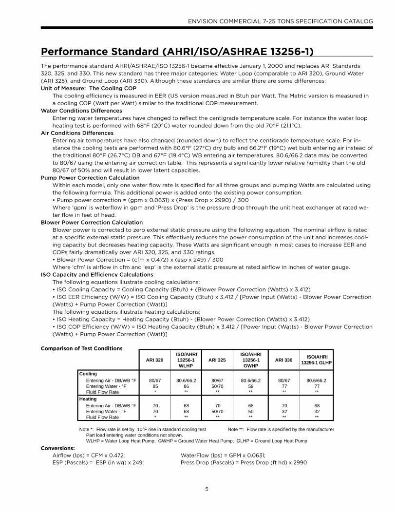
The performance standard AHRI/ASHRAE/ISO 13256-1 became effective January 1, 2000 and replaces ARI Standards
320, 325, and 330. This new standard has three major categories: Water Loop (comparable to ARI 320), Ground Water
(ARI 325), and Ground Loop (ARI 330). Although these standards are similar there are some differences:
Unit of Measure: The Cooling COPThe cooling efficiency is measured in EER (US version measured in Btuh per Watt. The Metric version is measured in
a cooling COP (Watt per Watt) similar to the traditional COP measurement.
Water Conditions DifferencesEntering water temperatures have changed to reflect the centigrade temperature scale. For instance the water loop
heating test is performed with 68°F (20°C) water rounded down from the old 70°F (21.1°C).
Air Conditions DifferencesEntering air temperatures have also changed (rounded down) to reflect the centigrade temperature scale. For in-
stance the cooling tests are performed with 80.6°F (27°C) dry bulb and 66.2°F (19°C) wet bulb entering air instead of
the traditional 80°F (26.7°C) DB and 67°F (19.4°C) WB entering air temperatures. 80.6/66.2 data may be converted
to 80/67 using the entering air correction table. This represents a significantly lower relative humidity than the old
80/67 of 50% and will result in lower latent capacities.
Pump Power Correction CalculationWithin each model, only one water flow rate is specified for all three groups and pumping Watts are calculated using
the following formula. This additional power is added onto the existing power consumption.
• Pump power correction = (gpm x 0.0631) x (Press Drop x 2990) / 300
Where ‘gpm’ is waterflow in gpm and ‘Press Drop’ is the pressure drop through the unit heat exchanger at rated wa-
ter flow in feet of head.
Blower Power Correction CalculationBlower power is corrected to zero external static pressure using the following equation. The nominal airflow is rated
at a specific external static pressure. This effectively reduces the power consumption of the unit and increases cool-
ing capacity but decreases heating capacity. These Watts are significant enough in most cases to increase EER and
COPs fairly dramatically over ARI 320, 325, and 330 ratings.
• Blower Power Correction = (cfm x 0.472) x (esp x 249) / 300
Where ‘cfm’ is airflow in cfm and ‘esp’ is the external static pressure at rated airflow in inches of water gauge.
ISO Capacity and Efficiency CalculationsThe following equations illustrate cooling calculations:
• ISO Cooling Capacity = Cooling Capacity (Btuh) + (Blower Power Correction (Watts) x 3.412)
• ISO EER Efficiency (W/W) = ISO Cooling Capacity (Btuh) x 3.412 / [Power Input (Watts) - Blower Power Correction
(Watts) + Pump Power Correction (Watt)]
The following equations illustrate heating calculations:
• ISO Heating Capacity = Heating Capacity (Btuh) - (Blower Power Correction (Watts) x 3.412)
• ISO COP Efficiency (W/W) = ISO Heating Capacity (Btuh) x 3.412 / [Power Input (Watts) - Blower Power Correction
(Watts) + Pump Power Correction (Watt)]
Comparison of Test Conditions
Conversions: Airflow (lps) = CFM x 0.472; WaterFlow (lps) = GPM x 0.0631; ESP (Pascals) = ESP (in wg) x 249; Press Drop (Pascals) = Press Drop (ft hd) x 2990
Performance Standard (AHRI/ISO/ASHRAE 13256-1)( / / )
ARI 320ISO/AHRI 13256-1 WLHP
ARI 325ISO/AHRI 13256-1 GWHP
ARI 330 ISO/AHRI 13256-1 GLHP
CoolingEntering Air - DB/WB °F 80/67 80.6/66.2 80/67 80.6/66.2 80/67 80.6/66.2Entering Water - °F 85 86 50/70 59 77 77Fluid Flow Rate * ** ** ** ** **
HeatingEntering Air - DB/WB °F 70 68 70 68 70 68Entering Water - °F 70 68 50/70 50 32 32Fluid Flow Rate * ** ** ** ** **
Note *: Flow rate is set by 10°F rise in standard cooling test Note **: Flow rate is specified by the manufacturerPart load entering water conditions not shown.WLHP = Water Loop Heat Pump; GWHP = Ground Water Heat Pump; GLHP = Ground Loop Heat Pump

6
ENVISION COMMERCIAL 7-25 TONS SPECIFICATION CATALOG
AHRI/ISO 13256-1 Performance Ratings/ gEnglish (IP) Units
Model
Flow Rate
Water Loop Heat Pump Ground Water Heat Pump Ground Loop Heat Pump
CoolingEWT 86°F
HeatingEWT 68°F
CoolingEWT 59°F
HeatingEWT 50°F
CoolingEWT 77°F
HeatingEWT 32°F
gpm cfm Capacity
BtuhEER
Btuh/W Capacity
BtuhCOP
CapacityBtuh
EERBtuh/W
Capacity Btuh
COP Capacity
BtuhEER
Btuh/W Capacity
BtuhCOP
NLH080 22.0 2600 73,000 15.5 77,700 4.7 79,000 22.5 65,800 4.2 76,000 17.7 51,300 3.5
NLH095 24.0 3200 85,500 15.6 91,000 4.8 95,000 23.0 78,000 4.3 91,200 18.1 61,600 3.5
NLH120 28.0 3600 113,000 13.8 140,600 4.6 129,000 21.9 115,000 4.1 119,500 16.2 89,000 3.4
NLV080 22.0 2600 76,000 16.5 85,000 5.0 84,000 24.2 71,000 4.4 83,000 19.7 55,000 3.7
NLV095 24.0 2800 91,000 17.2 100,000 5.2 101,000 25.7 83,000 4.6 95,000 19.6 65,000 3.8
NLV120 28.0 3600 115,000 15.5 136,000 5.1 135,000 24.3 107,500 4.4 122,000 18.0 83,000 3.6
NLV160* 35.0 5000 166,000 18.9 154,000 5.1 178,000 25.3 130,000 4.6 171,000 21.0 97,000 3.7
NLV180* 45.0 5600 180,000 17.1 190,000 5.0 187,000 22.2 149,000 4.3 185,000 18.5 109,000 3.4
NLV240* 60.0 7600 240,000 16.3 296,000 5.2 264,000 22.5 237,000 4.6 246,000 17.4 184,000 3.8
NLV300* 75.0 9500 284,000 17.3 353,000 5.4 314,000 24.5 286,000 4.8 291,000 19.0 224,000 4.2
Cooling capacities based upon 80.6°F DB, 66.2°F WB entering air temperatureHeating capacities based upon 68°F DB, 59°F WB entering air temperatureAll ratings based upon 208V operation.* Ratings for models NLV/NXV160-300 are outside the scope of the AHRI Water to Air/Brine to Air Heat Pumps Certification Program.
12/9/08

7
ENVISION COMMERCIAL 7-25 TONS SPECIFICATION CATALOG
The Envision SeriesNearly 25 years ago WaterFurnace led the way by designing and manufacturing watersource heat pumps for use in geo-
thermal closed loop applications. In 2003 WaterFurnace developed the first R410A watersource heat pump product line.
Now the Envision Series breaks ground again by providing the first 30 EER and 5 COP (ISO 13256-1 GLHP) and the first
20 EER 6 COP (ISO 13256-1 WLHP) rated water-source heat pump on the market. Higher efficiency also means less heat
rejected and ultimately shorter earth loops. WaterFurnace quality is well known and respected and is a result of quality
engineering and manufacturing in the state of the art Fort Wayne, Indiana plant. The Envision Series provides:
• Highest efficiencies and lowest operating costs.
• Broadest R410A product line.
• Standard or extended range (geothermal) operation.
• Blower packages for low static applications.
• Oversized motors for high static applications.
• IAQ features.
• Quiet operation.
• Flexible control options.
• WaterFurnace Quality.
Vertical ModelsNLV080-300 (7-25 tons)
NXV080-300 (7-25 tons)
Horizontal ModelsNLH080-120 (7-10 tons)
NXH080-120 (7-10 tons)

8
ENVISION COMMERCIAL 7-25 TONS SPECIFICATION CATALOG
The Envision Series cont.
Product Features: Vertical CabinetEnvision Vertical units are designed for high efficiency, maximum flexibility and primary servicing from the front and side.
These cabinets are field convertible top and side discharge, and are available in two sizes.
A true left and right return option is available.
Powder coated and fully
insulated heavy gauge
steel cabinet
Permanently-lubricated
blower motor All-Aluminum oversized
rifled tube lanced fin air
coil (optional AlumiSealTM
coating)
Adjustable motor mounts
Microprocessor Controls:
ABC - Standard
UPC - Optional
Easily removable
access panels
Fully insulated
refrigerant and
water lines
Environmentally friendlyEnvironmentally friendly
R-410A Refrigerant
Adjustable blower
sheaves
Scroll compressors (2)
Internally trapped
condensate line
Flush mount water connectionsFlush mo
(back up wrench not needed)
Left hand return Right hand return

9
ENVISION COMMERCIAL 7-25 TONS SPECIFICATION CATALOG
Reversing valve
Scroll Compressors (2)
Product Features: Horizontal CabinetThe Envision Horizontal units provide high efficiency, maximum flexibility, and primary servicing from the front. These
units are available in one cabinet size.
Four blower deck options are available. Factory or field conversion option of end or side discharge using switchable access panels and a factory only option of true left or right return air coil.
The Envision Series cont.
Right hand return
with end discharge
Right hand return
with side discharge
Bidi i l
expansion valve
Dynamically balanced
forward curved
centrifugal blower
acterial resistant Ba
omposite drain panco
Flush mount water
connections (backup
wrench not required)
vy duty galvanized Hea
steel cabinet w/factory
mounted support rails
Easy adjustment motor mmount
Left hand return
with end discharge with side discharge
10
ENVISION COMMERCIAL 7-25 TONS SPECIFICATION CATALOG
High Efficiency
Envision Series is the highest efficiency units available. Large oversized air coils, water to refrigerant heat exchangers and scroll compressors provide extremely efficient operationand produce the first 30 EER and 5 COP (ISO 13256-1 GLHP)water-source heat pump on the market. This efficiency means the Envision Series requires less loop than any product on the market. This can mean significant savings on commercialprojects.
Quiet OperationAll Envision Series product is AHRI 260 sound rated using third party sound testing. Room Noise Criteria Curves (NC Curve) may be calculated using data from the AHRI 260 ratings giving the engineer total flexibility in assuring a quiet environment. Please refer to our separate catalog WaterFurnace SoundRatings and Performance Catalog concerning this standardand Envision sound performance data.
Standard Features
• Large low rpm blower.
• Heavy gauge cabinet and rails on horizontals to hang
for vibration isolation.
• Quiet scroll compressors in all models
• 2-dimension refrigerant piping vibration loops to isolate
the compressor.
• All interior cabinet surfaces including the compressor
compartment are insulated with 1/2 in. [12.7 mm] thick
1-1/2lb [681 g] density, surface coated, acoustic type
glass fiber insulation.
Super Quiet Option
An optional SuperQuiet Sound Package is also available for a modest cost features:
• Multi-density laminate lined compressor blanket
designed to completely surround the compressor on all
six sides and suppress low frequency noise.
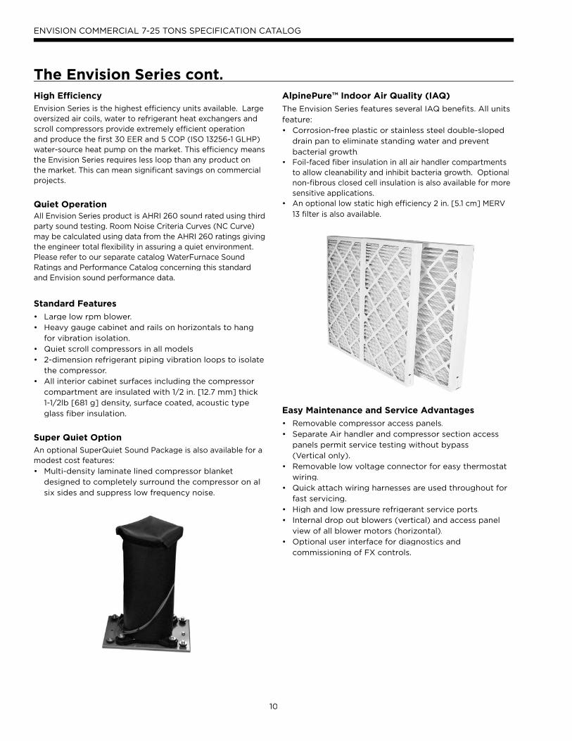
AlpinePure™ Indoor Air Quality (IAQ)
The Envision Series features several IAQ benefits. All units
feature:
• Corrosion-free plastic or stainless steel double-sloped
drain pan to eliminate standing water and prevent
bacterial growth.• Foil-faced fiber insulation in all air handler compartments to allow cleanability and inhibit bacteria growth. Optional non-fibrous closed cell insulation is also available for more sensitive applications.• An optional low static high efficiency 2 in. [5.1 cm] MERV
13 filter is also available.
Easy Maintenance and Service Advantages
• Removable compressor access panels.
• Separate Air handler and compressor section access
panels permit service testing without bypass
(Vertical only).
• Removable low voltage connector for easy thermostat
wiring.
• Quick attach wiring harnesses are used throughout for
fast servicing.
• High and low pressure refrigerant service ports.
• Internal drop out blowers (vertical) and access panel
view of all blower motors (horizontal).
• Optional user interface for diagnostics and
commissioning of FX controls.
The Envision Series cont.

11
ENVISION COMMERCIAL 7-25 TONS SPECIFICATION CATALOG
Secondary Drain Option (Special)
Some local building authority’s interpretation of codes
require more condensate overflow protection than standard
microprocessor based condensate sensors offer. In these
areas a full secondary drain pan might be required causing
both increased cost and unit service access issues. In many
of these cases a secondary drain option can be added to
the unit to pass this local interpretation of condensate
drain redundancy. This option adds a second PVC drain
connection to the drain pan at a higher level. This can be
ordered as a special and is only availabe in plastic.
Factory Quality• All refrigerant brazing is performed in a nitrogen
environment.
• Computer controlled deep vacuum and refrigerant
charging system.
• All joints are leak detected for maximum leak rate of
less than 1/4 oz. per year.
• Computer bar code equipped assembly line insures all
components are correct.
• All units are computer run-tested with water to verify
both function and performance.
The Envision Series cont.

12
ENVISION COMMERCIAL 7-25 TONS SPECIFICATION CATALOG
Inside the Envision SeriesRefrigerant
Envision products all feature zero ozone depletion and low
global warming potential R-410A refrigerant.
Cabinet
All vertical units are all constructed of corrosion resistant
galvanized sheet metal with optional white polyester
powder coat paint rated for more than 1000 hours of salt
spray. Large lift-out access panels provide access to the
compressor section from four sides. Refrigerant circuit is
designed to allow primary serviceability from the front. 1
horizontal and 2 vertical cabinets are provided for applica-
tion flexibility. Air handler access panels allow servicing
of the blower motor, blower, and drain pan. The blower
motor and blower can be completely serviced or replaced
without removal of the unit. Side or top discharge option
is available on vertical units
Flexible configurations include 4 blower deck options for
horizontals and a true left and right return on both hori-
zontal and vertical.
Filter Rack
A 2 in. [5.1 cm] disposable filter is standard. An optional 2
in. MERV 13 for high efficiency filtration is available.
Compressors
High efficiency R410A scroll compressors are used on every model. Scrolls provide both the highest efficiency available and great reliability.
Electrical Box
Unit controls feature quick con-nect wiring harnesses for easyservicing. Separate knockouts for LV, and two for power on two sides allow easy access tothe control box. Large 75VAtransformer assures adequate controls power for accessories.
Water ConnectionsFlush mount FPT water connection fittings allow one wrench leak-free connections and do not require a backup wrench.
Drain Pan
Bacteria resistant composite drain pan is sloped to pro-
mote complete drainage and will never rust or corrode.
Complete drainage helps to inhibit bacterial or microbial
growth. Vertical units feature an internally trapped con-
densate line using clear pvc hose for easy inspection and
reduced installation cost. Stainless steel drain pans are
available for 7-25 ton units.
Thermostatic Expansion Valve
All Envision models utilize a balanced port bi-directional
thermostatic expansion valve (TXV) for refrigerant meter-
ing. This allows precise refrigerant flow in a wide range of
entering water variation (20 to 120°F [-7 to 49°C]) found
in geothermal systems. The TXV is located in the com-
pressor compartment for easy access.
13
ENVISION COMMERCIAL 7-25 TONS SPECIFICATION CATALOG
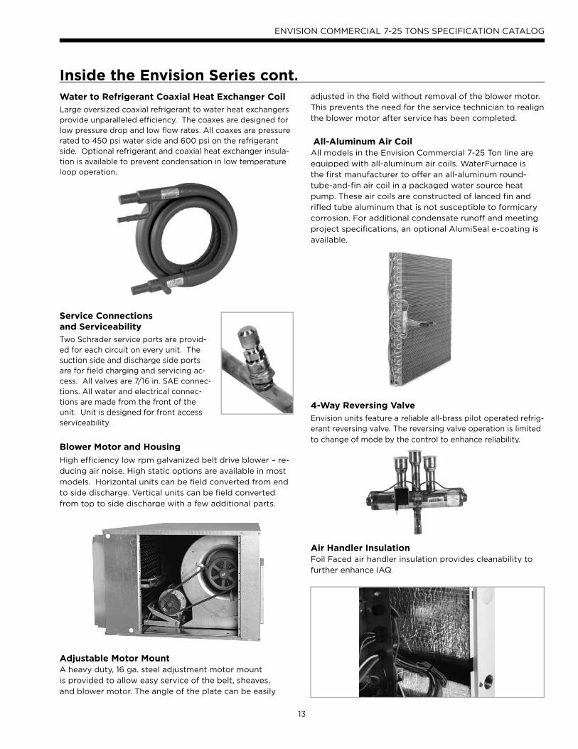
Water to Refrigerant Coaxial Heat Exchanger Coil
Large oversized coaxial refrigerant to water heat exchangers provide unparalleled efficiency. The coaxes are designed for low pressure drop and low flow rates. All coaxes are pressure rated to 450 psi water side and 600 psi on the refrigerant side. Optional refrigerant and coaxial heat exchanger insula-tion is available to prevent condensation in low temperature loop operation.
Service Connectionsand Serviceability
Two Schrader service ports are provid-ed for each circuit on every unit. The suction side and discharge side portsare for field charging and servicing ac-cess. All valves are 7/16 in. SAE connec-tions. All water and electrical connec-tions are made from the front of theunit. Unit is designed for front accessserviceability.
Blower Motor and Housing
High efficiency low rpm galvanized belt drive blower – re-
ducing air noise. High static options are available in most
models. Horizontal units can be field converted from end
to side discharge. Vertical units can be field converted
from top to side discharge with a few additional parts.
Adjustable Motor MountA heavy duty, 16 ga. steel adjustment motor mount
is provided to allow easy service of the belt, sheaves,
and blower motor. The angle of the plate can be easily
adjusted in the field without removal of the blower motor.
This prevents the need for the service technician to realign
the blower motor after service has been completed.
All-Aluminum Air CoilAll models in the Envision Commercial 7-25 Ton line are
equipped with all-aluminum air coils. WaterFurnace is
the first manufacturer to offer an all-aluminum round-
tube-and-fin air coil in a packaged water source heat
pump. These air coils are constructed of lanced fin and
rifled tube aluminum that is not susceptible to formicary
corrosion. For additional condensate runoff and meeting
project specifications, an optional AlumiSeal e-coating is
available.
4-Way Reversing Valve
Envision units feature a reliable all-brass pilot operated refrig-erant reversing valve. The reversing valve operation is limited
to change of mode by the control to enhance reliability.
Air Handler InsulationFoil Faced air handler insulation provides cleanability to
further enhance IAQ.
Inside the Envision Series cont.

14
ENVISION COMMERCIAL 7-25 TONS SPECIFICATION CATALOG
Controls - Aurora Base Control
Aurora ‘Base’ Control
NOTE: Refer to the Aurora Base Control Application and
Troubleshooting Guide and the Instruction Guide: Aurora
Interface and Diagnostics (AID) Tool for additional information.
Control FeaturesSoftware ABC Standard Version 2.0
Single or Dual Capacity CompressorsEither single or dual capacity compressors can be operated.
Variable Speed ECM
Blower Motor Option (If Applicable)A Variable Speed ECM blower motor can be driven directly using the onboard PWM output. Four blower speeds are available based upon the G, Y1, Y2, and W input signals to the board. The blower speeds can be changed either by the ECM manual configurations mode method or by using theAurora AID Tool directly. All four blower speeds can be set to the same speed if desired.
5-Speed ECM Blower Motor Option (If Applicable)A 5-Speed ECM blower motor will be driven directly usingthe thermostat connections. Any of the G, Y1, or Y2/W signals can drive any of the 5 available pre-programmed blower speeds on the motor. All 5 Series "G" vintage unitswill be wired this way at the factory.
Other Control Features• Random start at power up• Anti-short cycle protection• High and low pressure cutouts• Loss of charge• Water coil freeze detection• Air coil freeze detection• Over/under voltage protection• Condensate overflow sensor• Load shed• Dehumidification (where applicable)• Emergency shutdown• Hot gas reheat operation (where applicable)• Diagnostic LED• Test mode push button switch• Two auxiliary electric heat outputs• Alarm output• Accessory output with N.O. and N.C.• Modbus communication (master)• Modbus communication (slave)
Field Selectable Options via HardwareDIP Switch (SW1) – Test/Configuration Button (See SW1 Operation Table)
Test ModeThe control is placed in the test mode by holding the push button switch SW1 for 2 - 5 seconds. In test mode most of the control timings will be shortened by a factor of sixteen(16). LED3 (green) will flash at 1 second on and 1 secondoff. Additionally, when entering test mode LED1 (red) will flash the last lockout one time. Test mode will automaticallytime out after 30 minutes. Test mode can be exited by pressing and holding the SW1 button for 2 to 5 seconds orby cycling the power. NOTE: Test mode will automatically be exited after 30 minutes.
ECM Configuration Mode (If Applicable)The control is placed in the ECM configuration mode by holding the pushbutton switch SW1 for 5 to 10 seconds, thehigh, low, and “G” ECM speeds can be selected by following the LED display lights. LED2 (yellow) will fast flash when entering the ECM configuration. When setting “G” speedLED3 (green) will be continuously lit, for low speed LED1(red) will be continuously lit, and for high speed both LED3(green) and LED1 (red) will be continuously lit. During theECM configuration mode LED2 (yellow) will flash each of the 12 possible blower speeds 3 times. When the desired speed is flashed press SW1, LED2 will fast flash until SW1 is released. “G” speed has now been selected. Next selectlow speed, and high speed blower selections following the same process above. After third selection has been made, the control will exit the ECM configuration mode. Aux fanspeed will remain at default or current setting and requiresthe AID Tool for adjustment.
Reset Configuration ModeThe control is placed in reset configuration mode by holding the push button switch SW1 for 50 to 60 seconds.This will reset all configuration settings and the EEPROM back to the factory default settings. LED3 (green) will turn off when entering reset configuration mode. Once LED3(green) turns off, release SW1 and the control will reset.
DIP Switch (SW2)SW2-1 FP1 Selection – Low water coil temperature limit
setting for freeze detection. On = 30°F; Off = 15°F.SW2-2 FP2 Selection – On = 30°F; Off = N/ASW2-3 RV – O/B - thermostat type. Heat pump
thermostats with “O” output in cooling or “B”output in Heating can be selected. On = O; Off = B.
SW2-4 Access Relay Operation (P2)and 2-5
Access Relay Operation SW2-4 SW2-5
Cycle with Blower ON ON
Cycle with Compressor OFF OFF
Water Valve Slow Opening ON OFF
Cycle with Comm. T-stat Hum Cmd OFF ON

15
ENVISION COMMERCIAL 7-25 TONS SPECIFICATION CATALOG
Controls - Aurora Base Control cont. Cycle with Blower - The accessory relay will cycle withrthe blower output.
Cycle with Compressor - The accessory relay will cycle rwith the compressor output.
Water Valve Slow Opening - The accessory relay willgcycle and delay both the blower and compressor output for 90 seconds.
SW2-6 CC Operation – selection of single or dual capacity compressor. On = Single Stage; Off = Dual Capacity
SW2-7 Lockout and Alarm Outputs (P2) – selection of a continuous or pulsed output for both the LO andALM Outputs. On = Continuous; Off = Pulsed
SW2-8 Future Use
Alarm Jumper Clip SelectionFrom the factory, ALM is connected to 24 VAC via JW2. By cutting JW2, ALM becomes a dry contact connected to ALG.
ECM Blower SpeedsThe blower speeds can be changed either by using the ECM manual configurations mode method or by using theAurora AID Tool directly (see Instruction Guide: Aurora Interface and Diagnostics (AID) Tool topic).
Field Selectable Options via Software(Selectable via the Aurora AID Tool)ECM Blower SpeedsAn ECM blower motor can be driven directly using the onboard PWM output. Four blower speeds are available, based upon the “G”, Y1 (low), Y2 (high), and Aux inputsignals to the board. The blower speeds can be changed either by the ECM manual configurations mode method (see ECM Configuration Mode topic) or by using the Aurora AID Tool directly. All four blower speeds can be set to the same speed if desired. Aux blower speed will remain at default orcurrent setting and requires the AID Tool for adjustment.
Safety FeaturesThe following safety features are provided to protect the compressor, heat exchangers, wiring and other componentsfrom damage caused by operation outside of design conditions.
Fuse – a 3 amp automotive type plug-in fuse providesprotection against short circuit or overload conditions.
Anti-Short Cycle Protection – 4 minute anti-short cycle protection for the compressor.
Random Start – 5 to 80 second random start upon power up.
Fault Retry – in the fault condition, the control will stage off ythe outputs and then “try again” to satisfy the thermostat Y input call. Once the thermostat input calls are satisfied,the control will continue on as if no fault occurred. If 3consecutive faults occur without satisfying the thermostat Y input call, then the control will go to Lockout mode.
Lockout – when locked out, the blower will operate continuously in “G” speed, and PSC blower motor output will remain on. The Alarm output (ALM) and Lockout output (L) will be turned on. The fault type identification displayLED1 (Red) shall flash the fault code. To reset lockoutconditions with SW2-8 On, thermostat inputs “Y1”, “Y2”, and “W” must be removed for at least 3 seconds. To resetlockout conditions with SW2-8 Off, thermostat inputs “Y1”,“Y2”, “W”, and “DH” must be removed for at least 3 seconds. Lockout may also be reset by turning power off for at least 30 seconds or by enabling the emergency shutdown input for at least 3 seconds.
Lockout With Emergency Heat - if the control is locked outin the heating mode, and a Y2 or W input is received, the control will operate in the emergency heat mode while thecompressor is locked out. The first emergency heat output will be energized 10 seconds after the W input is received, and theblower will shift to high speed. If the control remains locked out, and the W input is present, additional stage of emergency heat will stage on after 2 minutes. When the W input is removed, all of the emergency heat outputs will turn off, and the ECM blower will shift to “G” speed and PSC blower motor output will remain on.
High Pressure – fault is recognized when the Normally Closed High Pressure Switch, P4-9/10 opens, no matter how momentarily. The High Pressure Switch is electrically in series with the Compressor Contactor and serves as a hard-wired limit switch if an overpressure condition should occur.
Low Pressure - fault is recognized when the Normally Closed Low Pressure Switch, P4-7/8 is continuously open for 30 seconds. Closure of the LPS any time during the 30 second recognition time restarts the 30 second continuous open requirement. A continuously open LPS shall not berecognized during the 2 minute startup bypass time.
Loss of Charge – fault is recognized when the NormallyClosed Low Pressure Switch, P4-7/8 is open prior to thecompressor starting.
Condensate Overflow - fault is recognized when thewimpedance between this line and 24 VAC common or chassisground drops below 100K ohms for 30 seconds continuously.
Freeze Detection (Coax) - set points shall be either 30°For 15°F. When the thermistor temperature drops below the selected set point, the control shall begin countingdown the 30 seconds delay. If the thermistor value rises above the selected set point, then the count should reset.The resistance value must remain below the selected set point for the entire length of the appropriate delay to berecognized as a fault. This fault will be ignored for the initial 2 minutes of the compressor run time.
Freeze Detection (Air Coil) - uses the FP2 input to protect against ice formation on the air coil. The FP2 input willoperate exactly like FP1 except that the set point is 30 degrees and is not field adjustable.

16
ENVISION COMMERCIAL 7-25 TONS SPECIFICATION CATALOG
Controls - Aurora Base Control cont. Over/Under Voltage Shutdown - An over/under voltagecondition exists when the control voltage is outside therange of 18 VAC to 30 VAC. If the over/under voltage shutdown lasts for 15 minutes, the lockout and alarm relay will be energized. Over/under voltage shutdown is self-resetting in that if the voltage comes back within range of 18 VAC to 30 VAC for at least 0.5 seconds, then normal operation is restored.
Operation DescriptionPower Up - The unit will not operate until all the inputs andsafety controls are checked for normal conditions. The unit has a 5 to 80 second random start delay at power up. Then the compressor has a 4 minute anti-short cycle delay afterthe random start delay.
Standby In standby mode, Y1, Y2, W, DH, and G are not yactive. Input O may be active. The blower and compressorwill be off.
Heating OperationSingle Compressor Heating, 2nd Stage (Y1, Y2)The compressor will be staged to full capacity 20 seconds after Y2 input is received. The ECM blower will shift to high speed seconds after the Y2 input is received.
Dual Compressor Heating, 2nd Stage (Y1, Y2)In dual compressor operation, two ABC boards used in 24 VAC operation, there will be a Y2 call to the Y1 input on the second ABC. The compressor will stage to full capacity 30 seconds after Y1 input is received to the second board.
Single Compressor Heating, 3rd Stage (Y1, Y2, W)The hot water pump is de-energized and the first stage of electric heat is energized 10 seconds after the W command is received. If the demand continues the second stage of electric heat will be energized after 5 minutes.
Dual Compressor Heating, 3rd Stage (Y1, Y2, W) - The first stage of electric heat is energized 10 seconds after the W command is received. If the demand continuesthe second stage of electric heat will be energized after 5 minutes
Emergency Heat (W) - The blower will be started on “G” speed, 10 seconds later the first stage of electric heat will be turned on. 5 seconds after the first stage of electric heat is energized the blower will shift to Aux speed. If theemergency heat demand is not satisfied after 2 minutes the second electric heat stage will be energized.
Blower (G) - The blower will start immediately uponreceiving a thermostat G command. If there are no other commands from the thermostat the ECM will run on “G”speed until the G command is removed. Regardless of blower input (G) from the thermostat, the blower will remain on for 30 seconds at the end of each heating cycle.
Cooling OperationIn all cooling operations, the reversing valve directly tracks the O input. Thus, anytime the O input is present, the reversing valve will be energized.
Single Compressor Cooling, 2nd Stage (Y1, Y2, 0)The compressor will be staged to full capacity 20 secondsafter Y2 input was received. The ECM blower will shift to high speed 15 seconds after the Y2 input was received.
Dual Compressor Cooling, 2nd Stage (Y1, Y2, O)In dual compressor operation, two ABC boards used in 24 VAC operation, there will be a Y2 call to the Y1 input on thesecond ABC. The compressor will stage to full capacity 30 seconds after Y1 input is received to the second board.
Blower (G) - The blower will start immediately uponreceiving a thermostat G command. If there are no other commands from the thermostat the ECM will run on “G”speed until the G command is removed. Regardless ofblower input (G) from the thermostat, the blower will remain on for 30 seconds at the end of each heating, cooling, and emergency heat cycle.
Dehumidification (Y1, O, DH or Y1, Y2, O, DH) - When a DH command is received from the thermostat during a compressor call for cooling the ECM blower speed will bereduced by 15% to increase dehumidification.
Emergency Shutdown - Four (4) seconds after a valid ESinput, P2-7 is present, all control outputs will be turned offand remain off until the emergency shutdown input is no longer present. The first time that the compressor is startedafter the control exits the emergency shutdown mode, there will be an anti-short cycle delay followed by a random start delay. Input must be tied to common to activate.
Continuous Blower Operation - The blower output will be energized any time the control has a G input present, unless the control has an emergency shutdown inputpresent. The blower output will be turned off when G input is removed.
Load Shed - The LS input disables all outputs with the exception of the blower output. When the LS input has been cleared, the anti-short cycle timer and random start timerwill be initiated. Input must be tied to common to activate.

17
ENVISION COMMERCIAL 7-25 TONS SPECIFICATION CATALOG
Controls - Aurora Base Control cont.
CC2
Fact
ory
Fault
ALG
ALM
LSES
ACC
c
Status
AuroraTM BaseControl
RV – K1
CC
2
CC – K2
CC Hi – K3
Fan – K4
Alarm – K5
Acc – K6
ACC
no
ACC
nc
O/BCRLO G Y1 Y2 W DH
3A-F
use
O/BCRLO G Y1 Y2 W DH
LOG
HICCGCCFGFR
HPHPLP
FP2FP2FP1
REVREV
CFM
PWM
ECM PWM
Fact
ory
Factory Fan Connection
R R
CC
C
C
R
(-)
(+)
RS
485
EH2C
EH1C
CO
(+)(-)RC
RS4
85Ex
pFa
ctor
y
Com1
Com2
Config
G
G
G
YR
SW1 Test
FP1 – 15oF/30oF
JW2 - Alarm
P11
P5
P2 P1
P8
P7
P9
P6
P3
SW2
P13P4 FP2 – 15oF/30oF
RV – B/O
ACC – Dip 1
ACC – Dip 2
CC – Dual/SingleL – Pulse/Continuous
Reheat/Normal
Fact
ory
Use
Field ConnectionsField Connections
C
LP
FP1
F
CC
G
Y1
1
2
3
4
5
6
7
8
Off On
N/A
RS4
85 N
ET
EH1LED 1
LED 3
LED 2
LED 5
LED 4
5.0 in.
6.25
in.
5.5 in.5.
75 in
.
Aurora Interface and Diagnostics (AID) ToolThe Aurora Interface and Diagnostics (AID) Tool isa device that is a memberof the Aurora network.The AID Tool is used totroubleshoot equipment which uses the Auroracontrol via Modbus RTU communication. The AID Tool provides diagnostics, fault management, ECM setup, and system configuration capabilities to the Aurora family of controls. An AID Tool is recommended, althoughnot required, for ECM airflow settings. The AID Tool simplyplugs into the exterior of the cabinet in the AID Tool port.
ABC Control Board Layout
Aurora ‘Base’ Control LED DisplaysThese three LEDs display the status, configuration, and fault codes for the control. These can also be read in plainEnglish via the Aurora AID Tool.
Status LED (LED3, Green)
Description of Operation Fault LED, Green
Normal Mode ON
Control is Non-functional OFF
Test Mode Slow Flash
Lockout Active Fast Flash
Dehumidification Mode Flash Code 2
(Future Use) Flash Code 3
(Future Use) Flash Code 4
Load Shed Flash Code 5
ESD Flash Code 6
(Future Use) Flash Code 7
Configuration LED (LED2, Yellow)
Description of Operation Configuration LED, Yellow
No Software Overwritten Flashing ECM Setting
DIP Switch was Overwritten Slow Flash
ECM Configuration Mode Fast Flash
Fault LED (LED1, Red)
Red Fault LEDLED Flash
Code*Lockout
Reset/Remove
AB
C B
asi
c F
au
lts
Normal - No Faults OFF –
Fault - Input 1 No Auto
Fault - High Pressure 2 Yes Hard or Soft
Fault - Low Pressure 3 Yes Hard or Soft
Fault - Freeze Detection FP2 4 Yes Hard or Soft
Fault - Freeze Detection FP1 5 Yes Hard or Soft
Fault - Condensate Overflow 7 Yes Hard or Soft
Fault - Over/Under Voltage 8 No Auto
Fault - FP1 & FP2 Sensor Error 11 Yes Hard or Soft
NOTE: All codes >11 use long flash for tens digit and short flash for the ones digit. 20, 30, 40, 50, etc. are skipped.
18
ENVISION COMMERCIAL 7-25 TONS SPECIFICATION CATALOG
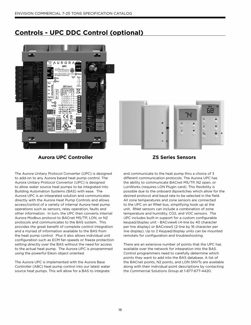
Controls - UPC DDC Control (optional)( p )
The Aurora Unitary Protocol Converter (UPC) is designedto add-on to any Aurora based heat pump control. The Aurora Unitary Protocol Convertor (UPC) is designed to allow water source heat pumps to be integrated into Building Automation Systems (BAS) with ease. The Aurora UPC is an integrated solution and communicatesdirectly with the Aurora Heat Pump Controls and allowsaccess/control of a variety of internal Aurora heat pumpoperations such as sensors, relay operation, faults and other information. In turn, the UPC then converts internal Aurora Modbus protocol to BACnet MS/TP, LON, or N2 protocols and communicates to the BAS system. This provides the great benefit of complete control integrationand a myriad of information available to the BAS fromthe heat pump control. Plus it also allows individual unitconfiguration such as ECM fan speeds or freeze protection setting directly over the BAS without the need for accessto the actual heat pump. The Aurora UPC is programmed using the powerful Eikon object oriented.
The Aurora UPC is implemented with the Aurora Base Controller (ABC) heat pump control into our latest water source heat pumps. This will allow for a BAS to integrate
and communicate to the heat pump thru a choice of 3different communication protocols. The Aurora UPC hasthe ability to communicate BACnet MS/TP, N2 open, orLonWorks (requires LON Plugin card). This flexibility is possible due to the onboard dipswitches which allow for thedesired protocol and baud rate to be selected in the field. All zone temperatures and zone sensors are connectedto the UPC on an RNet bus, simplifying hook up at the unit. RNet sensors can include a combination of zonetemperature and humidity, CO2, and VOC sensors. TheUPC includes built-in support for a custom configurablekeypad/display unit - BACview6 (4-line by 40 characterper line display) or BACview5 (2-line by 16 character per line display). Up to 2 Keypad/display units can be mountedremotely for configuration and troubleshooting.
There are an extensive number of points that the UPC has available over the network for integration into the BAS. Control programmers need to carefully determine whichpoints they want to add into the BAS database. A list of the BACnet points, N2 points, and LON SNVTs are availablealong with their individual point descriptions by contacting the Commercial Solutions Group at 1-877-677-4420.
Aurora UPC Controller ZS Series Sensors

19
ENVISION COMMERCIAL 7-25 TONS SPECIFICATION CATALOG
Controls - UPC DDC Control (optional) cont.( p )
Aurora UPC Features• Rugged enclosure made of GE C2950 Cycoloy plastic
• Built-in surge transient protection circuitry
• Operating range of -20° to 140°F; 10 to 95% relative hu-
midity, non-condensing
• Onboard CR123A battery has a life of 10 years with 720
hours of cumulative power outage
• Multi-Protocol field selectable communication port
that supports:
• EIA-485 BACnet MS/TP @ 9600, 19.2k, 38.4k, 76.8k baud
• Metasys N2 Open
• LonWorks TP/FT-10 (Requires optional LON plug-in
communication card)
• Status of all unit operating conditions and fault lockouts
• Visual LED’s for status of power, network communication,
processor operation, and errors
• Provides gateway into Aurora heat pump controls for
unsurpassed control flexibility
• Network point for commanding unit into load shed
• Network point for commanding unit into
emergency shutdown
• Network points to assist in fan speed selection
• Network points for freeze protection settings
• Heating and cooling control from a remotely located
zone sensor
• Rnet communication port which allows for multiple Rnet
zone sensors (5) to be connected for space temperature
averaging if desired.
• Local laptop or BACview connection for field service
• FCC, UL and CE listed. BTL Certification is pending
N2
BACnetB t
onWorkLo ks
BAS
Rnet
ModbusM s
Aurora UPC Optional Features• BACview handheld display, needed for field configuration
of fan speeds, set points, etc.
• AID Tool for Aurora ABC configuration
and troubleshooting.
• Aurora Advanced Control adds the Aurora AXB
expansion board and provides added I/O and
standard features
• Optional Sensor Kits (requires Aurora Advanced
Control with AXB - Future Availability on Select
Models/Configurations)
• Refrigeration Monitoring – provides Suction and
discharge pressure, Suction, liquid line temps and
superheat and subcooling.
• Performance Monitoring – provides entering and
leaving loop water temperatures, loop flow rate as well
as heat of extraction or rejection rate into the loop.
• Energy Monitoring – provides real-time power
measurement (Watt) of compressor, fan, auxiliary heat
and zone pump.
• Graphics packages available in the future

20
ENVISION COMMERCIAL 7-25 TONS SPECIFICATION CATALOG
Port 1a is used to
communicate to the
Building Automation
System (BAS). This
port’s settings are
configured through
the onboard dip
switches.
Port 2 is used to com-
municate to the Au-
rora Base Controller
(ABC).
Port 1b is used for the
LonWorks plugin.
Rnet port is used
for communicating
zone sensors.
BACview or local
laptop connection.
24Vac
Dip switches for
configuring the
communication
port protocol
and baud rate
for the BAS port.
Mac address
is set by 2
rotary dials.
Aurora Touch InterfaceUtilizing a touch-screen interface, the UPC provides a
technician the ability to configure and diagnose equipment
at the unit or from any room sensor for added accessibility
and simpler troubleshooting. The technician will have
full access to equipment status, parameter values,
temperature, and humidity sensing as well as access to
alarm and trend history. With website-like navigation,
the Aurora Touch Interface is easy to use and provides
important insight into the system so your building can
operate as efficiently as possible.
Controls - UPC DDC Control (optional) cont.( p )

21
ENVISION COMMERCIAL 7-25 TONS SPECIFICATION CATALOG
1. Leaving Air Temperature (LAT) Sensor – This 10 kOhm
NTC sensor is factory installed on all UPC equipped
heat pumps. It typically is attached to wiring inside
the blower cabinet on the suction side of the blower.
This sensor is attached on ABC FP2 pins available as
LAT AU-30.
1. Compressor Proving Sensors – This optional factory
installed current sensor is connected to confirm
compressor operation via the power wires. The sensor
is attached at ABC Y1 and available at point BV-65.
1. Valve End Switch – This optional input is setup for a field
installed flow valve end switch. This end switch input is
attached at ABC Y2 and available at point BV-67.
1. Fan Proving Sensors – This optional factory installed
current sensor is connected to confirm fan operation
via the power wires. The sensor is attached at ABC G
and available at point BV-33.
1. Occupancy Sensor - This standard feature includes a
field installed and wired room sensor with occupancy
sensor typically found in DDC systems. The RNet
room sensors can be found thru your commercial
representative. The occupancy Sensors are attached at
ABC 0 and can be found at point BV-49.
1. Dirty Filter Switch – This optional field installed switch
is connected to confirm dirty filter operation. The
dirty filter switch can be found thru your commercial
representative. The sensor is attached at ABC W and
available at point BV-63.
2. Fault, Configuration, and Status Codes – The codes
can be visible to the BAS if desired
Fault LED (LED1, Red)
Red Fault LEDLED Flash
Code *Lockout
Reset/ Remove
Fault Condition Summary
AB
C B
asi
c F
au
lts
Normal - No Faults Off -
Fault-Input 1 No Auto Tstat input error. Autoreset upon condition removal.
Fault-High Pressure 2 Yes Hard or Soft HP switch has tripped (>600 psi)
Fault-Low Pressure 3 Yes Hard or Soft Low Pressure Switch has tripped (<40 psi for 30 continuous sec.)
Fault-Freeze Detection FP2 4 Yes Hard or Soft Freeze protection sensor has tripped (<15 or 30 degF for 30 continuous sec.)
Fault-Freeze Detection FP1 5 Yes Hard or Soft Freeze protection sensor has tripped (<15 or 30 degF for 30 continuous sec.)
Fault-Condensate Overflow 7 Yes Hard or Soft Condensate switch has shown continuity for 30 continuous sec.
Fault-Over/Under Voltage 8 No Auto Instantaneous voltage is out of range. **Controls shut down until resolved.
Fault-FP1 & 2 Snsr Error 11 Yes Hard or Soft If FP1 or 2 Sensor Error
AB
C &
AX
B A
dvan
ce
d F
au
lts Fault-Compressor Monitor 10 Yes Hard or Soft Open Crkt, Run, Start or welded cont
Non-CriticAXBSnsrErr 13 No Auto Any Other Sensor Error
CriticAXBSnsrErr 14 Yes Hard or Soft Sensor Error for EEV or HW
Alert-HotWtr 15 No Auto HW over limit or logic lockout. HW pump deactivated.
Fault-VarSpdPump 16 No Auto Alert is read from PWM feedback.
Not Used 17 No Auto IZ2 Com Fault. Autoreset upon condition removal.
Non-CritComErr 18 No Auto Any non-critical com error
Fault-CritComErr 19 No Auto Any critical com error. Auto reset upon condition removal
Alarm - Low Loop Pressure 21 No Auto Loop pressure is below 3 psi for more than 3 minutes
Alarm - Home Automation 1 23 No Auto Closed contact input is present on Dig 2 input - Text is configurable
Alarm - Home Automation 2 24 No Auto Closed contact input is present on Dig 3 input - Text is configurable
NOTES:*All codes >11 use long flash for tens digit and short flash for the ones digit. 20, 30, 40, 50 etc. are skipped!Alert’ is a noncritical sensor or function that has failed. Normal operation of the heat pump is maintained but service is desired at some point.
Fault LED (LED1, Red)
Red Fault LEDLED Flash
Code*Lockout
Reset/Remove
AB
C B
asi
c F
au
lts
Normal - No Faults OFF –
Fault - Input 1 No Auto
Fault - High Pressure 2 Yes Hard or Soft
Fault - Low Pressure 3 Yes Hard or Soft
Fault - Freeze Detection FP2 4 Yes Hard or Soft
Fault - Freeze Detection FP1 5 Yes Hard or Soft
Fault - Condensate Overflow 7 Yes Hard or Soft
Fault - Over/Under Voltage 8 No Auto
Fault - FP1 & FP2 Sensor Error 11 Yes Hard or Soft
NOTE: All codes >11 use long flash for tens digit and short flash for the ones digit. 20, 30, 40, 50, etc. are skipped.
Aurora Base Fault Codes (ABC Only)
Aurora Advanced Fault Codes (ABC + AXB Expansion Board)
Controls - UPC DDC Control (optional) cont.( p )

22
ENVISION COMMERCIAL 7-25 TONS SPECIFICATION CATALOG
Status LED (LED3, Green)
Description of Operation Fault LED, Green
Normal Mode ON
Control is Non-functional OFF
Test Mode Slow Flash
Lockout Active Fast Flash
Dehumidification Mode Flash Code 2
Load Shed Flash Code 5
Emergency Shutdown Flash Code 6
On Peak Mode Flash Code 7
(Future Use) Flash Code 8
(Future Use) Flach Code 9
Configuration LED (LED2, Yellow)
Description of Operation Configuration LED, Yellow
No Software Overwritten ECM Setting
DIP Switch Overwritten Slow Flash
ECM Configuration Mode Fast Flash
Reset Configuration Mode OFF
Aurora Base or Advanced Control Configuration andStatus Codes
9. Alarm Relay – The Alarm relay (ALM) is factory
connected to 24 VAC via jumper JW2. By cutting JW2,
ABC ALM becomes a dry contact connected to ABC
ALG. The Relay is field switchable between Factory
setting as an Alarm output or available for other uses.
10. Accessory Relay1 – A configurable, accessory relay
on the ABC is provided that can be cycled with the
compressor, blower, or the Dehumidifier (DH) input.
A third (factory) setting cycles the relay with the
compressor but delays the compressor and blower
output for 90 sec. Source pump or slow opening
solenoid valves in well systems or variable speed
primary pumping systems would be a prime use of
this feature.
Access Relay Operation SW2-4 SW2-5
Cycle with Blower ON ON
Cycle with Compressor OFF OFF
Water Valve Slow Opening ON OFF
Cycle with Comm. T-stat Hum Cmd OFF ON
11. Electric Heat EH1 – A digital 24VDC output is provided
for electric heat powering. UPC’s Default programming
has EH1 set for AUX/ELEC Heat operation and will be
controlled using the UPC’s internal P.I.D. logic. However
it can be changed by the BAS to be network controlled.
12. Electric Heat EH2 – A digital VDC output is provided
for field options converted from the original EH2
output. Default UPC program has the EH2 output set
for Network Control but can be changed by the BAS
to be controlled by the UPC’s internal P.I.D. logic.
Controls - UPC DDC Control (optional) cont.( p )

23
ENVISION COMMERCIAL 7-25 TONS SPECIFICATION CATALOG
1. Accessory Relay2 – A second, configurable, accessory
relay on the AXB is provided that can be cycled with
the compressor 1 or 2 , blower, or the Dehumidifier (DH)
input. This is to complement the Accessory 1 Relay on
the ABC board.
2. Analog Out – A standard 0-10VDC analog output is
provided. This output can be used to drive modulat-
ing dampers etc.
3. Variable Speed Pump or Modulating Water Valve- This input and output are provided to drive and
monitor a variable speed pump. The VS pump output
is a PWM signal to drive the variable speed pump. The
minimum and maximum level are set using the AID
Tool. 75% and 100% are the default settings respec-
tively. The VS data input allows a separate PWM signal
to return from the pump giving fault and performance
information. Fault received from the variable speed
pump will be displayed as E16. Modulating Water Valve - This Variable speed PWM output is provided to
optionally drive a modulating water valve. Through ad-
vanced design a 0-10VDC valve can be driven directly
from the VS pump output. The minimum and maxi-
mum level are set in the same way as the VS pump
using the AID Tool. 75% and 100% are the default set-
tings respectively.
4. Loop Pump Slaving - This input and output are pro-
vided so that two units can be slaved together with a
common flow center. When either unit has a call for
loop pump, both unit’s loop pump relays and variable
speed pumps are energized. The flow center then can
simply be wired to either unit. The output from one
unit should be routed to the input of the other. If daisy
chained up to 16 heat pumps can be wired and slaved
together in this fashion.
Position DIP 4 DIP 5 Description
1 ON ON Cycles with Fan or ECM (or G)
2 OFF ONCycles with CC1 first stage of compressor
or compressor spd 1-12
3 ON OFFCycles with CC2 second stage of
compressor or compressor spd 7-12
4 OFF OFF Cycles with DH input from ABC board
Aurora Advanced Control Configuration and Options (Future Availability on Select Models/Configurations)
Controls - UPC DDC Control (optional) cont.( p )

24
ENVISION COMMERCIAL 7-25 TONS SPECIFICATION CATALOG
1. Energy Monitoring (Standard Sensor Kit on ‘Advanced’ models) - The Energy Monitoring Kit
includes two current transducers (blower and electric
heat) added to the existing two compressor sensors so
that the complete power usage of the heat pump can
be measured. The BACview Tool provides configuration
detail for the type of blower motor and a line voltage
calibration procedure to improve the accuracy. This
real time power usage information can be displayed on
the AID Tool and is available thru network points when
using BACnet or N2 Open.
• Compressor Current 1
• Compressor Current 2
• Fan Current
• Aux Heat Current
• Pump Selection
• Voltage
• Compressor Watts
• Fan Watts
• Aux Heat Watts
• Pump Watts (VS Only)
2. Refrigerant Monitoring (optional sensor kit) - The
optional Refrigerant Monitoring Kit includes two
pressure transducers, and three temperature sensors,
heating liquid line, suction temperature and existing
cooling liquid line (FP1). These sensors allow the
measurement of discharge and suction pressures,
suction and liquid line temperatures as well as
superheat and subcooling. This information can be
displayed on the BACview Tool, or the network when
using BACnet and N2.
• Htg Liquid Line
• Clg Liquid Line
• Discharge pressure
• Suction Pressure
• Discharge Saturated Temp
• Suction Saturated Temperature
• Superheat
• SubCooling
3. Performance Monitoring (optional sensor kit) - The
optional Performance Monitoring Kit includes: three
temperature sensors, entering and leaving water,
leaving air temperature and a water flow rate sensor.
With this kit, heat of extraction and rejection will
be calculated. This requires configuration using the
BACview Tool for selection of water or antifreeze.
• Leaving Air Temperature (supply)
• Alt Leaving Air Temperature (Supply)
• Entering Water Temperature
• Leaving Water Temperature
• Water Flow Meter
• Entering Air Temperature (from zone sensor)
• Brine Selection (water/antifreeze)
• Heat of Extraction/Rejection
Aurora Advanced Control Optional Sensor Kits (Future Availability on Select Models/Configurations)
Controls - UPC DDC Control (optional) cont.( p )

25
ENVISION COMMERCIAL 7-25 TONS SPECIFICATION CATALOG
ZS Series RNet Sensor Overview
The ZS Series line of intelligent zone sensors provides the
function and flexibility you need to manage the conditions
important to the comfort and productivity of the zone
occupants. The ZS sensors are available in a variety of
zone sensing combinations to address your application
needs. These combinations include temperature, relative
humidity, and indoor air quality (carbon dioxide or VOCs
(Volatile Organic Compounds)). They are built to be
flexible allowing for easy customization of what the user/
technician sees. Designed to work with the Aurora UPC
controllers the ZS sensor line includes the ZS Base, ZS
Plus, ZS Pro and ZS Pro-F.
The UPC uses a proprietary communication called Rnet
to receive the space temperature from the zone sensor.
This is done using (2) 18 AWG twisted pair unshielded
cables for a total of 4 wires connected to the Rnet port.
The sensor gets its power from the UPC controller and
connecting multiple sensors to one UPC will allow for space
temperature averaging. The UPC can support one ZS Pro
or ZS Pro F with up to four ZS standard sensors wired to
the Rnet port on the UPC for a total of 5 zone sensors.
The sensors use a precise 10k ohm thermistor with less
than 0.18°F drift over a ten year span, this allows for less
maintenance or re-calibration after installation. The sensors
also have a hidden communication port for connecting
a BACview or local laptop that provides access to the
equipment for commissioning and maintenance. The table
below shows the features of each of the four sensors that
are currently available.
ZS BaseZS Base
ZS Plus ZS Pro
ZS Pro-FZS Pro-F
Features ZS Base ZS Plus ZS Pro ZS Pro-F
Temp, CO2, Humidity, and VOC Options √ √ √ √
Neutral Color √ √ √ √
Addressable/supports daisy chaining √ √ √ √
Hidden communication port √ √ √ √
Mounts on a standard 2” by 4” electrical box √ √ √ √
Occupancy Status indicator LED √ √ √
Push button occupancy override √ √ √
Setpoint adjust √ √ √
Large, easy to read LCD √ √
Alarm indicator √ √
°F to °C conversion button √
Options Part Number Part Number Part Number Part Number
Temperature Only ZSU ZSUPL ZSUP ZSUPF
Temp with CO2 ZSU-C ZSUPL-C ZSUP-C ZSUPF-C
Temp with Humidity ZSU-H ZSUPL-H ZSUP-H ZSUPF-H
Temp with Humidity, CO2 ZSU-HC ZSUPL-HC ZSUP-HC ZSUPF-HC
Temp, Humidity, VOC ZSU-HV ZSUPL-HV ZSUP-HV ZSUPF-HV
Temp with VOC ZSU-V ZSUPL-V ZSUP-V ZSUPF-V
Controls - UPC DDC Control (optional) cont.( p )

26
ENVISION COMMERCIAL 7-25 TONS SPECIFICATION CATALOG
RNet Sensor Physical and Electrical Data
Sensing Element Range Accuracy
Temperature (on non-Humidity models) -4° to 122° F (-20° C to 50° C) ±0.35° F (0.2° C)
Temperature (on Humidity models) 50° F to 104° F (10° C to 40° C) ±0.5° F (0.3° C)
Humidity 10% to 90% ±1.8% typical
CO2 400 to 1250 PPM
1250 to 2000 PPM
±30PPM or +/-3% of reading (greater of two)
±5% of reading plus 30 PPM
VOC 0 to 2,000 PPM ±100 PPM
Power Requirements Sensor Type Power Required
Temperature Only All Models 12 Vdc @ 8 mA
Temperature with Humidity All Models 12 Vdc @ 15 mA (idle) to 190 mA
(CO2 measurement cycle)
Temp with VOC, or Temp/VOC/Humidity All Models 12 Vdc @ 60 mA
Temp with CO2 , or Temp/ CO2/Humidity All Models12 Vdc @ 15 mA (idle) to 190 mA
(CO2 measurement cycle)
Power Supply A controller supplies the Rnet sensor network with 12 Vdc @ 210 mA. Additional
power may be required for your application. See sensor ZS Installation Guide
Communication 115 kbps Rnet connection between sensor(s) and controller
15 sensors max per Rnet network; 5 sensors max per control program
Local Access Port For connecting a laptop computer to the local equipment for maintenance and commissioning
Environmental Operating Range 32° to 122° F (0° - 50° C), 10% to 90% relative humidity, non-condensing
Mounting Dimensions Standard 4”x 2” electrical box using provided 6/32” x 1/2” mounting screws
Controls - UPC DDC Control (optional) cont.( p )

27
ENVISION COMMERCIAL 7-25 TONS SPECIFICATION CATALOG
Hot Gas Reheat DescriptionThe refrigerant flows in normal heat pump path in heating
and cooling mode. During the Reheat mode, the operation
begins with superheated vapor leaving the compressor
going through the reheat valve to the reheat air coil. In the
reheat coil the high temperature high pressure gas reheats
the air exiting the unit to near neutral. Next, the refrigerant
exits the reheat coil and passes through a check valve,
which is used to prevent refrigerant flow into the reheat
coil during normal heating and cooling operation. The
refrigerant passes through the check valve and is then
diverted to the coaxial heat exchanger by the four way
reversing valve. The hot gas enters the coaxial heat
exchanger which will condense the gas to a high pressure
liquid due to heat being rejected to the loop fluid. The
high pressure liquid leaves the coax and enters the inlet of
the TXV. After passing through the TXV the low pressure
mixture of liquid/vapor refrigerant expands in the air coil
evaporating into a low pressure low temperature gas
and moves back through the reversing valve and into
the compressor suction. The cycle then starts again by
compressing the low pressure low temperature gas into
a superheated vapor. A small copper bleed line is located
on the reheat/reclaim valve to allow refrigerant that has
migrated to the reheat coil to escape.
Hot Gas Bypass DescriptionThe hot gas bypass (HGB) option is designed to limit
the minimum evaporating pressure in the cooling mode
to prevent the air coil from icing. The HGB valve senses
pressure at the outlet of the evaporator by an external
equalizer. If the evaporator pressure decreases to 115
psig the HGB valve will begin to open and bypass hot
discharge gas into the inlet of the evaporator. The
valve will continue to open as needed until it reaches
its maximum capacity. Upon a rise of suction pressure,
the valve will begin to close back off and normal cooling
operation will resume.
Hot Gas Reheat/Hot Gas Bypass/ yp

28
ENVISION COMMERCIAL 7-25 TONS SPECIFICATION CATALOG
Hot Gas Reheat DehumidificationOverviewDehumidification - The Need for Reheat
With tighter construction and more and more ventilation
air being introduced into buildings, there is more need
now than ever for proper humidity control. Ensuring
dehumidification can provide consistent employee
comfort, a reduction in mold liability, a reduction in
cooling costs. Reduced humidity also provides an
improvement in indoor air quality (IAQ) thru lower
humidity levels which can reduce allergen levels, inhibit
mold and bacterial growth, and provide an improved
computer environment. ASHRAE 90.1 speaks of an
acceptable humidity range in all commercial buildings.
Typical Reheat Applications
Reheat can be used wherever moisture is a problem.
Schools, high latent auditorium and theaters, makeup
air units*, and computer rooms are typical applications.
Although reheat equipped water source heat pumps
(wshp’s) can condition limited amounts of outdoor air, the
percentage of this outdoor air should never exceed 50%
of the return air to the unit limiting the mixed return air
temperature to a minimum of 50°F. When cold entering air
conditions are anticipated, hot gas bypass option should
be considered to prevent air coil freeze up.
*A dedicated outdoor air system (DOAS) should be
investigated for 100% outdoor air applications.
The Design of Reheat Equipmentt
Hot gas reheat can help maintain specific humidity levels m
and neutral air in a building. ASHRAE recommends a in
relative humidity range of 30-60% with levels greater o
than 65% making mold growth a possibility. Theg
dehumidification relative humidity set points of 57% e
(on) and 52% (off) are recommended. During reheat theec
leaving air temperature (LAT) will approximate neutral air.(L
The included chart (Leaving Air Temperature vs. Enteringv
Water and Air Conditions Chart) shows the LAT vs s
entering water temperature (EWT) to the unit at differing u
entering air conditions. At 86-90°F EWT the unit will
provide nearly neutral air.
Moisture Removal Capacity
The amount of moisture removal may be calculated by
subtracting the sensible cooling capacity from the total
cooling capacity in the equipment performance data of
the specifications catalog or submittal data. An example
is shown below:
Model NLV*080, 2600 cfm, 22 gpm, 90°F EWT
TC – SC = LC
78.0 – 57.8 MBtu/h = 20.2 MBtu/h
Where TC = total cooling capacity, SC=sensible capacity, LC=latent capacity
Leaving Air Temperature vs. Entering Water and Air Conditions Chart
Hot Gas Reheat/Hot Gas Bypass cont./ yp

29
ENVISION COMMERCIAL 7-25 TONS SPECIFICATION CATALOG
Hot Gas Reheat DehumidificationOverview cont.Btu/hr may be converted to lbs/hr or grains per hour as
shown in the equations below.
20,200 Btu/h / 1,069 Btu/lb of water vapor
at 80/67 DB/WB°F = 18.90 lbs/hr
18.90 lbs/hr x 7,000 grains/lb = 132,300 grains/hr
External Static Pressure AdjustmentWith a reheat coil option installed an adjustment for
external static pressure (ESP) needs to be made. The
following table will show the reduction in ESP for any
model relating coil air velocity and ESP.
Model NLV080, 2600 cfm,
H x W = SA
28 x 25 x 2 = 1400 in.2 = 9.72 ft.2
Where H=fin height of air coil, W=fin length of air coil, SA=fin surface area
Calculate air velocity, fpm, cfm / SA
2600 cfm / 9.72 ft.2 = 267 fpm
Refer to the ESP vs. Coil Velocity Table and look up the
fpm to find ESP increase. If air velocity is below 250 cfm
assume 0.10 increase in ESP. Interpolation of data within
the table is permitted.
ESP vs. Coil Velocity Table
Coil Velocity (fpm) 250 300 350 400
ESP Increase (in. wg.) 0.10 0.14 0.17 0.20
Hot Gas Bypass with Hot Gas Reheat Layout
Compressor
ReheatValve
RV
TXV
Suction
Discharge
CheckValve
Coax
AirCoil
Reh
eat
Co
il
Hot GasBypass Valve
Hot Gas Reheat/Hot Gas Bypass cont./ yp
30
ENVISION COMMERCIAL 7-25 TONS SPECIFICATION CATALOG
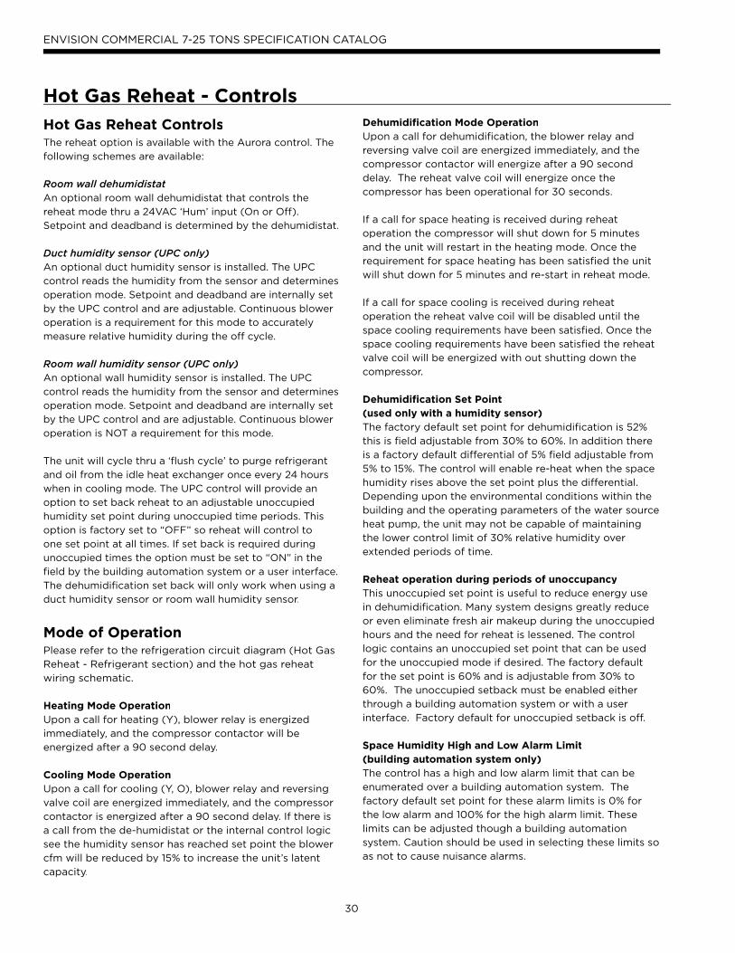
Hot Gas Reheat ControlsThe reheat option is available with the Aurora control. The
following schemes are available:
Room wall dehumidistatAn optional room wall dehumidistat that controls the
reheat mode thru a 24VAC ‘Hum’ input (On or Off).
Setpoint and deadband is determined by the dehumidistat.
Duct humidity sensor (UPC only)An optional duct humidity sensor is installed. The UPC
control reads the humidity from the sensor and determines
operation mode. Setpoint and deadband are internally set
by the UPC control and are adjustable. Continuous blower
operation is a requirement for this mode to accurately
measure relative humidity during the off cycle.
Room wall humidity sensor (UPC only)An optional wall humidity sensor is installed. The UPC
control reads the humidity from the sensor and determines
operation mode. Setpoint and deadband are internally set
by the UPC control and are adjustable. Continuous blower
operation is NOT a requirement for this mode.
The unit will cycle thru a ‘flush cycle’ to purge refrigerant
and oil from the idle heat exchanger once every 24 hours
when in cooling mode. The UPC control will provide an
option to set back reheat to an adjustable unoccupied
humidity set point during unoccupied time periods. This
option is factory set to “OFF” so reheat will control to
one set point at all times. If set back is required during
unoccupied times the option must be set to “ON” in the
field by the building automation system or a user interface.
The dehumidification set back will only work when using a
duct humidity sensor or room wall humidity sensor.
Mode of OperationPlease refer to the refrigeration circuit diagram (Hot Gas
Reheat - Refrigerant section) and the hot gas reheat
wiring schematic.
Heating Mode OperationUpon a call for heating (Y), blower relay is energized
immediately, and the compressor contactor will be
energized after a 90 second delay.
Cooling Mode OperationUpon a call for cooling (Y, O), blower relay and reversing
valve coil are energized immediately, and the compressor
contactor is energized after a 90 second delay. If there is
a call from the de-humidistat or the internal control logic
see the humidity sensor has reached set point the blower
cfm will be reduced by 15% to increase the unit’s latent
capacity.
Dehumidification Mode OperationUpon a call for dehumidification, the blower relay and
reversing valve coil are energized immediately, and the
compressor contactor will energize after a 90 second
delay. The reheat valve coil will energize once the
compressor has been operational for 30 seconds.
If a call for space heating is received during reheat
operation the compressor will shut down for 5 minutes
and the unit will restart in the heating mode. Once the
requirement for space heating has been satisfied the unit
will shut down for 5 minutes and re-start in reheat mode.
If a call for space cooling is received during reheat
operation the reheat valve coil will be disabled until the
space cooling requirements have been satisfied. Once the
space cooling requirements have been satisfied the reheat
valve coil will be energized with out shutting down the
compressor.
Dehumidification Set Point(used only with a humidity sensor)The factory default set point for dehumidification is 52%
this is field adjustable from 30% to 60%. In addition there
is a factory default differential of 5% field adjustable from
5% to 15%. The control will enable re-heat when the space
humidity rises above the set point plus the differential.
Depending upon the environmental conditions within the
building and the operating parameters of the water source
heat pump, the unit may not be capable of maintaining
the lower control limit of 30% relative humidity over
extended periods of time.
Reheat operation during periods of unoccupancyThis unoccupied set point is useful to reduce energy use
in dehumidification. Many system designs greatly reduce
or even eliminate fresh air makeup during the unoccupied
hours and the need for reheat is lessened. The control
logic contains an unoccupied set point that can be used
for the unoccupied mode if desired. The factory default
for the set point is 60% and is adjustable from 30% to
60%. The unoccupied setback must be enabled either
through a building automation system or with a user
interface. Factory default for unoccupied setback is off.
Space Humidity High and Low Alarm Limit(building automation system only)The control has a high and low alarm limit that can be
enumerated over a building automation system. The
factory default set point for these alarm limits is 0% for
the low alarm and 100% for the high alarm limit. These
limits can be adjusted though a building automation
system. Caution should be used in selecting these limits so
as not to cause nuisance alarms.
Hot Gas Reheat - Controls

31
ENVISION COMMERCIAL 7-25 TONS SPECIFICATION CATALOG
The Closed Loop Heat Pump Concept
The basic principle of a water source heat pump is the
transfer of heat into water from the space during cooling,
or the transfer of heat from water into the space during
heating. Extremely high levels of energy efficiency are
achieved as electricity is used only to move heat, not to
produce it. Using a typical WaterFurnace Envision Series,
one unit of electricity will move four to five units of heat.
When multiple water source heat pumps are combined
on a common circulating loop, the ultimate in energy
efficiency is created: The WaterFurnace units on
cooling mode are adding heat to the loop which the
units in heating mode can absorb, thus removing heat
from the area where cooling is needed, recovering and
redistributing that heat for possible utilization elsewhere
in the system. In modern commercial structures, this
characteristic of heat recovery from core area heat
generated by lighting, office equipment, computers,
solar radiation, people or other sources, is an important
factor in the high efficiency and low operating costs of
WaterFurnace closed source heat pump systems.
In the event that a building's net heating and cooling
requirements create loop temperature extremes,
Envision Series units have the extended range capacity
and versatility to maintain a comfortable environment
for all building areas. Excess heat can be stored for
later utilization or be added or removed in one of three
ways; by ground-source heat exchanger loops: plate
heat exchangers connected to other water sources,
or conventional cooler/boiler configurations. Your
WaterFurnace representative has the expertise and
computer software to assist in determining optimum
system type for specific applications.
The Closed Loop Advantage
A properly applied water source heat pump system
offers many advantages over other systems. First costs
are low because units can be added to the loop on an
"as needed basis"- perfect for speculative buildings.
Installed costs are low since units are self-contained
and can be located adjacent to the occupied space,
requiring minimal ductwork. Maintenance can be done
on individual units without system shut-down. Conditions
remain comfortable since each unit operates separately,
allowing cooling in one area and heating in another.
Tenant spaces can be finished and added as needed.
Power billing to tenants is also convenient since each unit
can be individually metered: each pays for what each
uses. Nighttime and/or weekend uses of certain areas are
possible without heating or cooling the entire facility. A
decentralized system also means if one unit should fault,
the rest of the system will continue to operate normally,
as well as eliminating air cross-contamination problems
and expensive high pressure duct systems requiring an
inefficient electric resistance reheat mode.
The Envision Approach
There are a number of proven choices in the type of
Envision Series system which would be best for any given
application. Most often considered are:
• Closed Loop/Ground-Source Systems utilize the stable
temperatures of the earth to maintain proper water source
temperatures (via vertical or horizontal closed loop heat
exchangers) for Envision Series extended range heat
pump system. Sizes range from a single unit through many
hundreds of units. When net cooling requirements cause
closed loop water temperatures to rise, heat is dissipated
into the cooler earth through buried high strength plastic
pipe "heat exchangers." Conversely if net space heating
demands cause loop heat absorption beyond that heat
Envision Application Notespp
Supply Water
Return Water
Pumps
EnvisionUnit
EnvisionUnit
EnvisionUnit
EnvisionUnit
EnvisionUnit
EnvisionUnit
Heater/Rejector
Closed Loop/Ground Source
Vertical

32
ENVISION COMMERCIAL 7-25 TONS SPECIFICATION CATALOG
In cooling dominated structures, the ground-source
surface water systems can be very cost effective
especially where local building codes require water
retention ponds for short term storage of surface run-off.
Sizing requirements for the surface water is a minimum of
500 sq. ft./ton of surface area at a minimum depth of 8
feet. WaterFumace should be contacted when designs for
heating dominated structures are required.
• Closed Loop/Ground Water Plate Heat ExchangerSystems utilize lake, ocean, well water or other water
sources to maintain closed loop water temperatures in
multi-unit Envision systems. A plate frame heal exchanger
isolates the units from any contaminating effects of the
water source, and allows periodic cleaning of the heat
exchanger during off peak hours.
Operation and benefits are similar to those for ground-
source systems. Due to the extended loop temperatures,
AHRI/ISO 13256-1 Ground Loop Heat Pumps are required
for this application. Closed loop plate heat exchanger
systems are applicable in commercial, marine, or industrial
structures where the many benefits of a water source heat
pump system are desired, regardless of whether the load
is heating or cooling dominated.
recovered from building core areas, the loop temperature
will fall causing heat to be extracted from the earth. Due
to the extended loop temperatures, AHRI/ISO 13256-1
Ground Loop Heat Pumps are required for this application.
Because auxiliary equipment such as a fossil fuel boiler
and cooling tower are not required to maintain the loop
temperature, operating and maintenance costs are very low.
Ground-source systems are most applicable in residential
and light commercial buildings where both heating and
cooling are desired, and on larger envelope dominated
structures where core heat recovery will not meet overall
heating loads. Both vertical and horizontally installed
closed-loops can be used. The land space required
for the "heat exchangers" is 100-250 sq. ft./ton on
vertical (drilled) installations and 750-1500 sq. ft./ton
for horizontal (trenched) installations. Closed loop heat
exchangers can be located under parking areas or even
under the building itself.
On large multi-unit systems, sizing the closed loop
heat exchanger to meet only the net heating loads and
assisting in the summer with a closed circuit cooling tower
may be the most cost effective choice.
• Closed Loop/Ground-Source Surface Water Systems also utilize the stable temperatures of Surface Water to
maintain proper water source temperatures for Envision
Series extended range heat pump systems. These
systems have all of the advantages of horizontal and
vertical closed loop systems. Due to the extended loop
temperatures, AHRI/ISO 13256-1 Ground Water or Ground
Loop Heat Pumps are required for this application.
Envision Application Notes cont.pp
Closed Loop/Ground SourceSurface Water
Closed Loop/Ground WaterPlate Heat Exchanger

33
ENVISION COMMERCIAL 7-25 TONS SPECIFICATION CATALOG
In ground water situations where scaling could be heavy
or where biological growth such as iron bacteria will be
present, a closed loop system is recommended. The heat
exchanger coils in ground water systems may, over a period
of time, lose heat exchange capabilities due to a buildup
of mineral deposits inside. These can be cleaned, but only
by a qualified service mechanic, as special solutions and
pumping equipment are required. Hot water generator coils
Water Qualityy
Material Copper 90/0 10 Cupronickel 316 Stainless SteelpH Acidity/yy Al// kalinity 7 - 9 7 - 9 7 - 9
ScalingCalcium and
Magnesium Carbonate(Total HaTT rdness)
less than 350 ppm(Total HaTT rdness)
less than 350 ppm(Total HaTT rdness)
less than 350 ppm
Corrosion
Hydrogen SulfideLess than 0.5 ppm (rotten egg
smell appears at 0.5 ppm)10 - 50 ppm Less than 1 ppm
Sulfates Less than 125 ppm Less than 125 ppm Less than 200 ppm
Chlorine Less than 0.5 ppm Less than 0.5 ppm Less than 0.5 ppm
Chlorides Less than 20 ppm Less than 125 ppm Less than 300 ppm
Carbon Dioxide Less than 50 ppm 10 - 50 ppm 10 - 50 ppm
Ammonia Less than 2 ppm Less than 2 ppm Less than 20 ppm
Ammonia Chloride Less than 0.5 ppm Less than 0.5 ppm Less than 0.5 ppm
Ammonia Nitrate Less than 0.5 ppm Less than 0.5 ppm Less than 0.5 ppm
Ammonia Hydroxide Less than 0.5 ppm Less than 0.5 ppm Less than 0.5 ppm
Ammonia Sulfate Less than 0.5 ppm Less than 0.5 ppm Less than 0.5 ppm
Total DiTT ssolved Solids (TDS) Less than 1000 ppm 1000 - 1500 ppm 1000 - 1500 ppm
LSI Index +0.5 to -0.5 +0.5 to -0.5 +0.5 to -0.5
Iron Fouling(Biological Growth)
Iron, FE2+ (Ferrous)Bacterial Iron Potential
< 0.2 ppm < 0.2 ppm < 0.2 ppm
Iron OxideLess than 1 ppm, above this level deposition will occur
Less than 1 ppm, above this level deposition will occur
Less than 1 ppm, above this level deposition will occur
ErosionSuspended Solids
Less than 10 ppm and filtered for max. of 600 micron size
Less than 10 ppm and filtered for max. of 600 micron size
Less than 10 ppm and filtered for max. of 600 micron size
Threshold Velocity(Fresh Water)
< 6 ft/sec// < 6 ft/sec// < 6 ft/sec//
NOTES: Grains = ppm divided by 17mg/L is equivalent to ppm
2/22/12
can likewise become scaled and possibly plugged. In areas
with extremely hard water, the owner should be informed
that the heat exchanger may require occasional flushing.
Units with cupronickel heat exchangers are recommended
for open loop applications due to the increased resistance
to build-up and corrosion, along with reduced wear caused
by acid cleaning.
Envision Application Notes cont.ppClosed LoopCooler - Boiler
• Closed Loop /Cooler-Boiler Systems utilize a closed heat
recovering loop with multiple water source heat pumps
in the more conventional manner. Typically a boiler is
employed to maintain closed loop temperatures above
60°F and a cooling tower to maintain loop temperatures
below 90°F. These systems are applicable in medium
to large buildings regardless of whether the load is
heating or cooling dominated. Due to the moderate loop
temperatures, AHRI/ISO 13256-1 Water Loop Heat Pumps
are required for this application.

34
ENVISION COMMERCIAL 7-25 TONS SPECIFICATION CATALOG
Typical Unit InstallationUnit Location
Locate the unit in an indoor area that allows for easy
removal of the filter and access panels. Location should
have enough space for service personnel to perform
maintenance or repair. Provide sufficient room to make
water, electrical and duct connection(s). If the unit is
located in a confined space, such as a closet, provisions
must be made for return air to freely enter the space
by means of a louvered door, etc. Any access panel
screws that would be difficult to remove after the unit
is installed should be removed prior to setting the unit.
On horizontal units, allow adequate room below the unit
for a condensate drain trap and do not locate the unit
above supply piping. Care should be taken when units are located in unconditioned spaces to prevent damage fromfrozen water lines and excessive heat that could damage electrical components.
Installing Vertical Units
Vertical units are available in left or right air return
configurations. Top flow vertical units should be mounted
level on a vibration absorbing pad slightly larger than the
base to provide isolation between the unit and the floor. It
is not necessary to anchor the unit to the floor.
WARNING: Before performing service or maintenanceoperations on a system, turn off main power switches to the indoor unit. If applicable, turn off the accessory heater power switch. Electrical shock could causepersonal injury.
Installing and servicing heating and air conditioning
equipment can be hazardous due to system pressure and
electrical components. Only trained and qualified service
personnel should install, repair or service heating and air
conditioning equipment. Untrained personnel can perform
the basic maintenance functions of cleaning coils and
cleaning and replacing filters.
All other operations should be performed by trained
service personnel. When working on heating and air
conditioning equipment, observe precautions in the
literature, tags and labels attached to the unit and other
safety precautions that may apply. Follow all safety codes.
Wear safety glasses and work gloves. Use a quenching
cloth for brazing operations and have a fire extinguisher
available.
90 deg elbow with vanes on supply
Sealed low velocity ductwork
Canvas connector
Flexible water and electrical connections
Vibration absorbing pad
Acoustic liningto elbow
Installation Notes

35
ENVISION COMMERCIAL 7-25 TONS SPECIFICATION CATALOG
Installing Horizontal Units
Horizontal units are available with side or end discharge
and may be field converted from one to the other.
Horizontal units are normally suspended from a ceiling by
four 1/2 in. diameter threaded rods. The rods are usually
attached to the unit by hanger bracket kits furnished with
each unit. Lay out the threaded rods per the dimensions
below. Assemble the hangers to the unit as shown. When
attaching the hanger rods to the bracket, a double nut is
required since vibration could loosen a single nut.
NOTE: The unit should be pitched approximately 1/4-inch towards the drain in both directions to facilitate the removal of condensate.
Some installations requIre placing a horizontal unit on an
attic floor. In this case, the unit should be set in a full size
secondary drain pan on top of a vibration absorbing pad.
The secondary drain pan prevents possible condensate
overflow or water leakage damage to the ceiling. The
secondary drain pan is usually placed on a plywood base
isolated from the ceiling joists by additional layers of
vibration absorbing material. Insulate supply plenum and
use at least one 90° elbow to reduce noise.
CAUTION: Do not use rods smaller than 1/2-inch diameter since they may not be strong enough to support the unit. The rods must be securely anchored to the ceiling.
NEED PHOTOHose Kit Illustration
Installation Notes cont.
NNNNNEEEEEEDDDD PPPPHHHHHOOOOOTTTTTOOOOOOOOOOOOOOOOOHosesesee KKKKititititit IIIIIllllususususustrtrtratatatioioionnn

36
ENVISION COMMERCIAL 7-25 TONS SPECIFICATION CATALOG
Water Piping
Piping is usually designed as ‘reverse return’ to equalize
flow paths through each unit. A short flexible pressure
rated hose is used to make connection to the fixed
building piping system. This hose is typically stainless
steel braid and includes a swivel fitting on one end
for easy removal and is flexible to help isolate the unit
for quieter operation . Isolation valves for servicing,
y-strainers for filtering and memory-stop flow valve or a
balancing valve can be provided for consistent water flow
through the unit.
All unit source water connections are fittings that accept
a male pipe thread (MPT). Insert the connectors by
hand, then tighten the fitting with a wrench to provide
a leakproof joint. The open and closed loop piping
system should include pressure/temperature ports for
serviceability. The proper water flow must be provided to
each unit whenever the unit operates. To assure proper
flow, use pressure/temperature ports to determine the
flow rate. These ports should be located at the supply
and return water connections on the unit. The proper
flow rate cannot be accurately set without measuring the
water pressure drop through the refrigerant-to-water heat
exchanger. Limit hose length to 10 feet per connection.
Check carefully for water leaks.
Condensate Drain
On vertical units, the internal condensate drain assembly
consists of a drain tube which is connected to the drain
pan, a 3/4 in. or 1 in. copper female adapter and a flexible
connecting hose. On vertical upflow units, a condensate
hose is inside all cabinets as a trapping loop; therefore, an
external trap is not necessary. On horizontal units, a PVC
stub is provided for condensate drain piping connection.
An external trap is required (see below). If a vent is
necessary, an open stand pipe may be applied to a tee
in the field-installed condensate piping. In order to work
properly, the vent must be after the trap and away from
the unit.
Installation Notes cont.
1.5 in. 1.5 in.3/4 in. PVC tube stub
3/4 in. PVCCoupling
Vent (if needed)
3/4 in. PVC
1/8 in. per foot

37
ENVISION COMMERCIAL 7-25 TONS SPECIFICATION CATALOG
Acoustical Considerations and Equipment Sound Performance
Sound Performance
The Envision Series is third party sound rated in ac-
cordance with AHRI 260. Please consult WaterFurnace
Sound Performance Data Catalog for details on the AHRI
standard and sound performance data.
Recommendations for Noise ReductionHorizontal Unit Location
• Specify equipment with quietest sound power ratings
• Do not locate units above areas with a required NC 40
or less
• Space WSHP at least 10 ft (3m) apart to avoid noise
summing of multiple units in a space.
• Maximize the height of the unit above the ceiling
(horizontal).
• Suspend unit with isolation grommets that are
appropriately rated to reduce vibrations (horizontal).
Vertical Unit Location• Specify equipment with quietest sound power ratings
• Space WSHP at least 10 ft (3m) apart to avoid noise
summing of multiple units in a space.
• Acoustic ceiling coatings can greatly reduce noise levels
in mechanical rooms.
• Mount unit on a sound absorbing pad, extruded
polystyrene, rubber or cork pad.
Ductwork• Insure return air grilles will not allow line of site noise to
transfer to adjacent space. Use a sound barrier or some
other material to isolate the grille from the unit. A
supply grille, boot and short piece of flex duct pointed
away from the unit can greatly attenuate equipment
noise.
• Use a canvas isolation duct connector at the supply and
return duct connection of the unit.
• Internally line the discharge and return duct within the
first 4-8 feet of unit with acoustic insulation. Install an
internally lined ‘L’ shaped return duct elbow at return
grille. Face the elbow away from adjacent units.
• Always install at least one 90° elbow in the discharge
duct to eliminate line of sight noise transmission of the
blower.
• Use turning vanes at all elbows and tees to reduce
turbulence.
• Limit supply duct velocities to less than 1000 fpm
• Design and install ductwork as stiff as possible
• Allow 3 duct diameters both up and down stream of
the unit before any fittings or transitions are installed.
• Use duct sealant on all duct joints.
• Install a short (2-4’) of flex duct on all branch ducts just
prior to discharge boot or diffuser to reduce vibration
and duct sound prior to delivery in the room.
• Locate the branch duct balancing damper as far away
from the diffuser as possible.
• In ceiling plenum systems, install an internally lined ‘L’
shaped return duct elbow at unit. Face the elbow away
from adjacent units (horizontal).
Installation Notes cont.
Insulated Return(optional)
90 deg elbowon supply
Flexible waterand electricalconnections
Acoustic liningto elbow
Turning vanesat elbows and
Tees
Branchdamper
upstreamFlex ductat diffuser
2-4 ft
Sealed lowvelocity
ductwork
Supply grillewith 2-3 ft offlex left openfor return air
Locate units overhallways where
possible
Canvasconnector
Locate return grille6 ft from unit

38
ENVISION COMMERCIAL 7-25 TONS SPECIFICATION CATALOG
Vertical Dimensional Data7-10 Tons
CONTROL BOXRIGHT RETURN
CONTROL BOX AND WATERLEFT RETURN
2’ PRIMARYSERVICE ACCESSFOR LEFT RETURN
2’ PRIMARY
CONTROL BOXRIGHT RETURN
SERVICE ACCESSFOR RIGHT RETURN
2’ SECONDARYSERVICE ACCESS
CONTROL BOXAND WATERLEFT RETURN
TOP DISCHARGE
2’ PRIMARYSERVICE ACCESSFOR LEFT RETURN
2’ PRIMARYSERVICE ACCESSFOR RIGHT RETURN
2’ SECONDARYSERVICE ACCESS
SIDE DISCHARGE
56 in[142.2 cm]
2 in [5.1 cm]
1 in [2.5 cm]
2 in [5.1 cm]
18.1 in [46 cm]
1.8 in [4.6 cm]
56 in[142.2 cm]
22.6 in[57.4 cm]
TOP PANELCOVER
58.1 in [147.6 cm]61.3 in [155.7 cm]
34.1 in[86.6 cm]
2.9 in[7.4 cm]
16.1 in[40.9 cm]
TOP VIEWLeft or Right Return
SIDE VIEWLeft or Right Return
34.1 in[86.6 cm]
58.1 in [147.6 cm]61.3 in [155.8 cm]
21.6 in[54.9 cm]
18.1 in[46.0 cm]
1.42 in[3.6 cm]
16.1 in[40.9 cm]
2.9 in[7.4 cm]
15.6 in[39.6 cm]12.5 in [31.8 cm]
36.3 in[92.2 cm]
2.6 in [6.6 cm]
DRAIN CONNECTION
WATER OUTWATER IN
ELECTRICALCONNECTIONS
ELECTRICALCONNECTIONS
AIR COILS
34.4 in[87.4 cm]
4.0 in [10.2 cm]2.2 in [5.6 cm]
10.1 in [25.7 cm]2.0 in
[5.1 cm]
2.2 in[5.6 cm]
7.2 in[18.3 cm]
LEFT RETURN RIGHT RETURN
15.6 in[39.6 cm]
4.0 in [10.2 cm]2.2 in [5.6 cm]
10.1 in [25.7 cm]
2.2 in[5.6 cm]
12.5 in [31.8 cm]
36.3 in[92.2 cm]
2.6 in [6.6 cm]
DRAIN CONNECTION
WATER OUTWATER IN
AIR COILS
34.4 in[87.4 cm]
7.2 in[18.3 cm]
2.0 in[5.1 cm]
TOP OR SIDE DISCHARGE
Legend AP = Alternate Service Panel BP = Blower Service Panel CP = Control Access Panel CMP = Compressor Service Panel
APCMP
APCMP
CPCP
CP CP
REV 2/11/08

39
ENVISION COMMERCIAL 7-25 TONS SPECIFICATION CATALOG
13-25 Tons
Vertical Dimensional Data cont.
LEFT RETURN
6.0 in15.2 cm
13.0 in33.0 cm
15.2 in38.7 cm
19.0 in48.2 cm
24.5 in62.2 cm
18.0 in45.7 cm
18.0 in45.7 cm
16.0 in40.6 cm
16.0 in40.6 cm
16.0 in40.6 cm
16.0 in40.6 cm
1.5 in3.7 cm
1.5 in3.7 cm
2.0 in5.1 cm
2.0 in5.1 cm
34.0 in86.4 cm
14.2 in36.1 cm
14.2 in36.1 cm
2.6 in6.5 cm
6.5 in16.5 cm
88.1 in223.8 cm
RIGHT RETURN
TOP DISCHARGESIDE DISCHARGE
88.1 in223.8 cm86.3 in219.1 cm
1.0 in2.5 cm
66.0 in167.5 cm
2.0 in5.1 cm
1.0 in2.5 cm
34.0 in86.4 cm
2.9 in7.3 cm
86.3 in219.1 cm
88.1 in223.8 cm
18.0 in45.8 cm
13.8 in35.1 cm
18.0 in45.8 cm
13.8 in35.1 cm
TOP PANEL COVER
2.9 in7.3 cm
66.0 in167.5 cm
2.0 in5.1 cm
DRAIN CONNECTION
ELECTRICAL CONNECTIONS
40.4 in102.6 cm
41.8 in106.2 cm
AIR COILSAIR COILS
41.8 in106.2 cm
40.4 in102.6 cm
15.2 in38.7 cm
19.0 in48.2 cm
24.5 in62.2 cm
2.6 in6.5 cm
6.5 in16.5 cm
6.0 in15.2 cm
13.0 in33.0 cm
1.7 in4.4 cm
1.7 in4.4 cm
DRAIN CONNECTION WATER OUT
WATER IN
WATER OUT
WATER IN
ELECTRICAL CONNECTIONS
2’ PRIMARYSERVICE ACCESS
2’ SECONDARYSERVICE ACCESS
2’ PRIMARYSERVICE ACCESS
2’ PRIMARYSERVICE ACCESS
Legend AP = Alternate Service Panel BP = Blower Service Panel CP = Control Access Panel CMP = Compressor Service Panel
CONTROL BOXAND WATER
RIGHT RETURN
CONTROL BOXAND WATER
LEFT RETURN
CONTROL BOXLEFT RETURN
APCMP
APCMP
CP CP
CPCP
CONTROL BOXRIGHT RETURN
TOP VIEWL or R Return
SIDE VIEWL or R Return
TOP OR SIDE DISCHARGE
REV 8/16/07
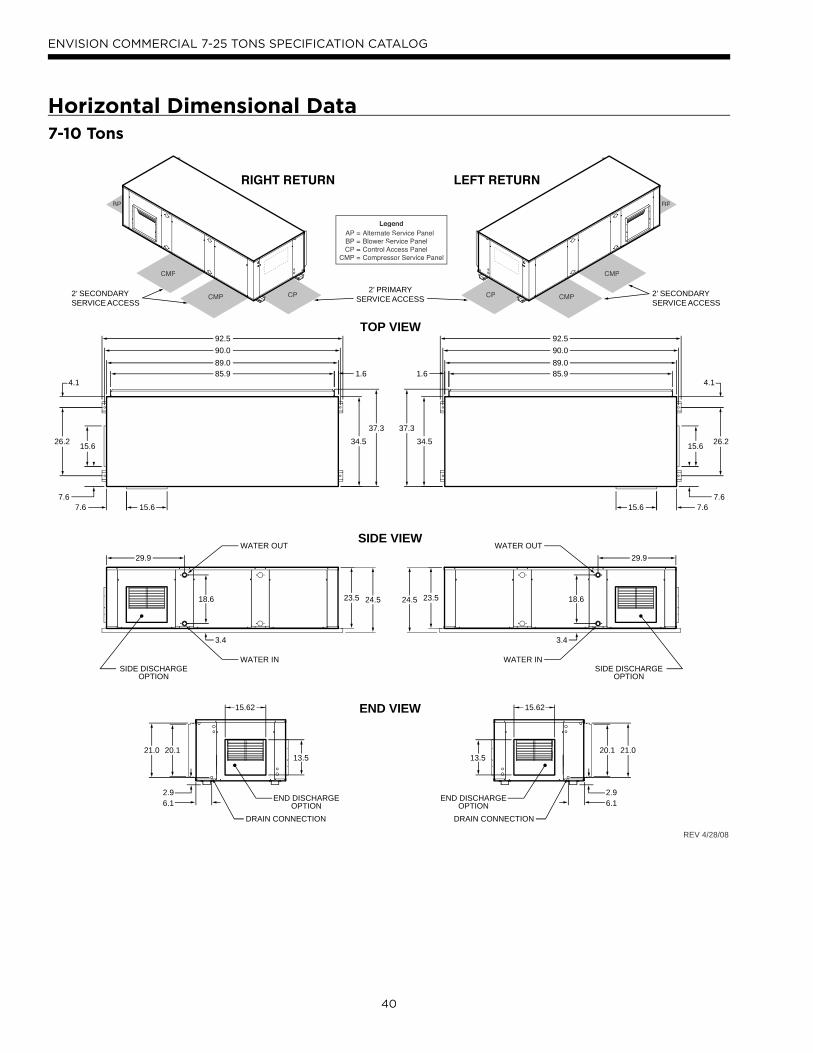
40
ENVISION COMMERCIAL 7-25 TONS SPECIFICATION CATALOG
Horizontal Dimensional Data
RIGHT RETURN LEFT RETURN
26.2
4.1
15.6
89.0
34.5
90.0
37.3
92.5
7.67.615.6
85.91.6
TOP VIEW
26.2
4.1
15.6
89.0
34.5
90.0
37.3
92.5
7.67.6 15.6
85.9 1.6
DRAIN CONNECTION
END DISCHARGEOPTION
15.62
13.5
2.96.1
20.121.0
END VIEW
DRAIN CONNECTION
END DISCHARGEOPTION
15.62
2.96.1
20.1 21.0
SIDE DISCHARGEWATER IN
WATER OUT
OPTION
SIDE VIEW
18.6
3.4
29.929.9
24.523.5
SIDE DISCHARGEWATER IN
WATER OUT
OPTION
18.6
3.4
29.929.9
24.5 23.5
13.5
Legend AP = Alternate Service Panel BP = Blower Service Panel CP = Control Access Panel CMP = Compressor Service Panel
CMP
CMP
CMP
CMP CPCP
BP BP
2’ PRIMARYSERVICE ACCESS
2’ SECONDARYSERVICE ACCESS
2’ SECONDARYSERVICE ACCESS
REV 4/28/08
7-10 Tons

41
ENVISION COMMERCIAL 7-25 TONS SPECIFICATION CATALOG
Hanger Bracket Locationsg
Top View
90.5
26.244.13
Mounting HardwareMounting Rod Layout - Left or Right Return 1/2 in. Threaded Rod
(not included)
Vibration Isolator
Washer (not included)
Hex Nuts (not included)
A B C DFront Front Back Back
Model Return / Discharge Left Right Right Left
Left / Side or End 30% 26% 22% 22%
Right / Side or End 26% 30% 22% 22%
Approximate
080 - 120
A B
CD
Controls
Horizontal Unit Corner Weight Distribution
Physical Datay
Horizontal Vertical
Model 080 095 120 080 095 120 160 180 240 300
Compressor (2 each) Copeland Scroll Copeland Scroll
Factory Charge R410A,
oz [kg] (per circuit)74 [2.10] 84 [2.38] 92 [2.61] 78 [2.21] 86 [2.44] 100 [2.83] 176 [4.99] 178 [5.05] 236 [6.69] 240 [6.80]
PSC Fan Motor & Blower
Fan Motor- hp [W] 1.5 [1120] 2.0 [1492] 3.0 [2238] 1.0 (746) 1.5 (1120) 2.0 (1492) 1.0 (746) 1.5 (1120) 2.0 (1492) 3.0 (2238)
Blower Wheel Size (Dia x
W), in. [mm]
12 x 12
[305 x 305]
12 x 12
[305 x 305]
12 x 12
[305 x 305]
15 x 11
[381 x 280]
15 x 11
[381 x 280]
15 x 11
[381 x 280]
15 x 11 (2)
[381 x 280]
15 x 11 (2)
[381 x 280]
15 x 11 (2)
[381 x 280]
15 x 11 (2)
[381 x 280]
Coax and Water Piping
Water Connections Size -
FPT - in [mm]
1 1/4
[31.75]
1 1/4
[31.75]
1 1/4
[31.75]
1 1/4
[31.75]
1 1/4
[31.75]
1 1/4
[31.75]
2
[50.8]
2
[50.8]
2
[50.8]
2
[50.8]
HWG Connection Size -
FPT - in [mm]N/A N/A N/A N/A N/A N/A N/A N/A N/A N/A
Coax & Piping Water
Volume - gal [l]2.87 [10.85] 3.20 [12.13] 3.46 [13.11] 2.87 [10.85] 3.20 [12.13] 3.46 [13.11] 6.50 [24.61] 6.50 [24.61] 7.00 [26.50] 7.00 [26.50]
Air Coil & Filters
Air Coil Dimensions (H x
W), in. [mm]
20 x 35
[508 x 889]
20 x 40
[508 x 1016]
20 x 40
[508 x 1016]
28 x 25
(711 x 635)
32 x 25
(813 x 635)
36 x 25
(915 x 635)
40 x 40 (2)
[1016 x 1016]
40 x 40 (2)
[1016 x 1016]
40 x 40 (2)
[1016 x 1016]
40 x 40 (2)
[1016 x 1016]
Air Coil Total Face Area,
ft2 [m2]9.74 [0.91] 11.11 [1.03] 11.11 [1.03] 9.72 (0.90] 11.10 (1.03) 12.50 (1.16) 22.22 [2.06] 22.22 [2.06] 22.22 [2.06] 22.22 [2.06]
Air Coil Tube Size, in [mm] 3/8 (9.52) 3/8 (9.52) 3/8 (9.52) 3/8 (9.52) 3/8 (9.52) 3/8 (9.52) 3/8 (9.52) 3/8 (9.52) 3/8 (9.52) 3/8 (9.52)
Air Coil Number of rows 3 3 3 3 3 4 3 3 3 3
Filter Standard - 2” [50.8],
in [mm]
20 x 20 (3)
[508 x 508]
20 x 25 (1)
[508 x 635]
20 x 20 (3)
[508 x 508]
20 x 25 (1)
[508 x 635]
20 x 20 (3)
[508 x 508]
20 x 25 (1)
[508 x 635]
28 x 36 (1)
(711 x 914)
30 x 36 (1)
(762 x 914)
28 x 36 (1)
(711 x 914)
30 x 36 (1)
(762 x 914)
28 x 36 (1)
(711 x 914)
30 x 36 (1)
(762 x 914)
40 x 42 (2)
(1016 x 1067)
40 x 42 (2)
(1016 x 1067)
40 x 42 (2)
(1016 x 1067)
40 x 42 (2)
(1016 x 1067)
Weight - Operating, lb
[kg]700 [318] 796 [361] 843 [382] 644 [292] 762 [346] 849 [385] 1175 [533] 1195 [542] 1350 [612] 1400 [635]
Weight - Packaged, lb
[kg]690 [313] 785 [356] 830 [376] 620 [281] 735 [333] 820 [372] 1180 [535] 1200 [544] 1355 [614] 1405 [637]
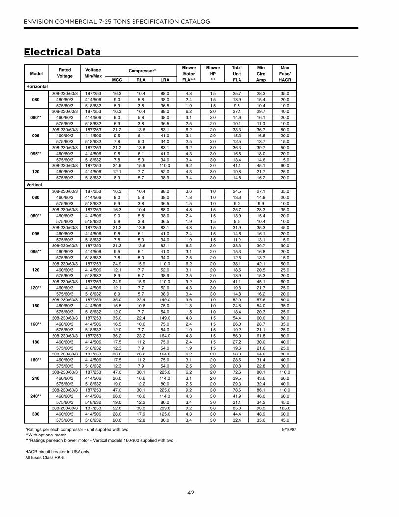
42
ENVISION COMMERCIAL 7-25 TONS SPECIFICATION CATALOG
Electrical Data
Rated Voltage Blower Blower Total Min Max
Voltage Min/Max Motor HP Unit Circ Fuse/MCC RLA LRA FLA*** *** FLA Amp HACR
Horizontal
208-230/60/3 187/253 16.3 10.4 88.0 4.8 1.5 25.7 28.3 35.0080 460/60/3 414/506 9.0 5.8 38.0 2.4 1.5 13.9 15.4 20.0
575/60/3 518/632 5.9 3.8 36.5 1.9 1.5 9.5 10.4 10.0208-230/60/3 187/253 16.3 10.4 88.0 6.2 2.0 27.1 29.7 40.0
080** 460/60/3 414/506 9.0 5.8 38.0 3.1 2.0 14.6 16.1 20.0575/60/3 518/632 5.9 3.8 36.5 2.5 2.0 10.1 11.0 10.0
208-230/60/3 187/253 21.2 13.6 83.1 6.2 2.0 33.3 36.7 50.0095 460/60/3 414/506 9.5 6.1 41.0 3.1 2.0 15.3 16.8 20.0
575/60/3 518/632 7.8 5.0 34.0 2.5 2.0 12.5 13.7 15.0208-230/60/3 187/253 21.2 13.6 83.1 9.2 3.0 36.3 39.7 50.0
095** 460/60/3 414/506 9.5 6.1 41.0 4.3 3.0 16.5 18.0 20.0575/60/3 518/632 7.8 5.0 34.0 3.4 3.0 13.4 14.6 15.0
208-230/60/3 187/253 24.9 15.9 110.0 9.2 3.0 41.1 45.1 60.0120 460/60/3 414/506 12.1 7.7 52.0 4.3 3.0 19.8 21.7 25.0
575/60/3 518/632 8.9 5.7 38.9 3.4 3.0 14.8 16.2 20.0
Vertical
208-230/60/3 187/253 16.3 10.4 88.0 3.6 1.0 24.5 27.1 35.0080 460/60/3 414/506 9.0 5.8 38.0 1.8 1.0 13.3 14.8 20.0
575/60/3 518/632 5.9 3.8 36.5 1.5 1.0 9.0 9.9 10.0208-230/60/3 187/253 16.3 10.4 88.0 4.8 1.5 25.7 28.3 35.0
080** 460/60/3 414/506 9.0 5.8 38.0 2.4 1.5 13.9 15.4 20.0575/60/3 518/632 5.9 3.8 36.5 1.9 1.5 9.5 10.4 10.0
208-230/60/3 187/253 21.2 13.6 83.1 4.8 1.5 31.9 35.3 45.0095 460/60/3 414/506 9.5 6.1 41.0 2.4 1.5 14.6 16.1 20.0
575/60/3 518/632 7.8 5.0 34.0 1.9 1.5 11.9 13.1 15.0208-230/60/3 187/253 21.2 13.6 83.1 6.2 2.0 33.3 36.7 50.0
095** 460/60/3 414/506 9.5 6.1 41.0 3.1 2.0 15.3 16.8 20.0575/60/3 518/632 7.8 5.0 34.0 2.5 2.0 12.5 13.7 15.0
208-230/60/3 187/253 24.9 15.9 110.0 6.2 2.0 38.1 42.1 50.0120 460/60/3 414/506 12.1 7.7 52.0 3.1 2.0 18.6 20.5 25.0
575/60/3 518/632 8.9 5.7 38.9 2.5 2.0 13.9 15.3 20.0208-230/60/3 187/253 24.9 15.9 110.0 9.2 3.0 41.1 45.1 60.0
120** 460/60/3 414/506 12.1 7.7 52.0 4.3 3.0 19.8 21.7 25.0575/60/3 518/632 8.9 5.7 38.9 3.4 3.0 14.8 16.2 20.0
208-230/60/3 187/253 35.0 22.4 149.0 3.6 1.0 52.0 57.6 80.0160 460/60/3 414/506 16.5 10.6 75.0 1.8 1.0 24.8 54.0 35.0
575/60/3 518/632 12.0 7.7 54.0 1.5 1.0 18.4 20.3 25.0208-230/60/3 187/253 35.0 22.4 149.0 4.8 1.5 54.4 60.0 80.0
160** 460/60/3 414/506 16.5 10.6 75.0 2.4 1.5 26.0 28.7 35.0575/60/3 518/632 12.0 7.7 54.0 1.9 1.5 19.2 21.1 25.0
208-230/60/3 187/253 36.2 23.2 164.0 4.8 1.5 56.0 61.8 80.0180 460/60/3 414/506 17.5 11.2 75.0 2.4 1.5 27.2 30.0 40.0
575/60/3 518/632 12.3 7.9 54.0 1.9 1.5 19.6 21.6 25.0208-230/60/3 187/253 36.2 23.2 164.0 6.2 2.0 58.8 64.6 80.0
180** 460/60/3 414/506 17.5 11.2 75.0 3.1 2.0 28.6 31.4 40.0575/60/3 518/632 12.3 7.9 54.0 2.5 2.0 20.8 22.8 30.0
208-230/60/3 187/253 47.0 30.1 225.0 6.2 2.0 72.6 80.1 110.0240 460/60/3 414/506 26.0 16.6 114.0 3.1 2.0 39.5 43.6 60.0
575/60/3 518/632 19.0 12.2 80.0 2.5 2.0 29.3 32.4 40.0208-230/60/3 187/253 47.0 30.1 225.0 9.2 3.0 78.6 86.1 110.0
240** 460/60/3 414/506 26.0 16.6 114.0 4.3 3.0 41.9 46.0 60.0575/60/3 518/632 19.0 12.2 80.0 3.4 3.0 31.1 34.2 45.0
208-230/60/3 187/253 52.0 33.3 239.0 9.2 3.0 85.0 93.3 125.0300 460/60/3 414/506 28.0 17.9 125.0 4.3 3.0 44.4 48.9 60.0
575/60/3 518/632 20.0 12.8 80.0 3.4 3.0 32.4 35.6 45.0
*Ratings per each compressor - unit supplied with two 9/10/07**With optional motor***Ratings per each blower motor - Vertical models 160-300 supplied with two.
HACR circuit breaker in USA onlyAll fuses Class RK-5
Compressor*Model

43
ENVISION COMMERCIAL 7-25 TONS SPECIFICATION CATALOG
Airflow in CFM with dry coil and clean air filter.
Rated CFMExternal Static Pressure (in. w.g.)
0.0 0.1 0.2 0.3 0.4 0.5 0.6 0.7 0.8 0.9 1.0 1.1 1.2 1.3 1.4 1.5MTR/SHEAVE 1.0 1.0 1.0 1.0 1.0 4.0 4.0 4.0 4.0 5.0 5.0 5.0 5.0
2200 BHP 0.37 0.40 0.43 0.47 0.52 0.59 0.65 0.71 0.75 0.78 0.81 0.86 0.90RPM 583 624 665 706 747 770 791 821 865 911 957 986 1015TURNS OPEN 5.0 4.0 3.0 2.0 1.0 3.0 2.0 1.0 0.0 3.5 3.0 2.5 2.0MTR/SHEAVE 1.0 1.0 1.0 1.0 1.0 4.0 4.0 4.0 4.0 5.0 5.0 5.0 5.0 5.0
2400 BHP 0.45 0.49 0.53 0.59 0.62 0.67 0.70 0.74 0.79 0.85 0.88 0.91 0.95 1.08RPM 582 623 664 705 746 765 790 820 861 906 938 970 1004 1030TURNS OPEN 5.0 4.0 3.0 2.0 1.0 3.0 2.0 1.0 0.0 4.0 3.0 2.5 2.0 1.5MTR/SHEAVE 1.0 1.0 1.0 1.0 3.0 3.0 3.0 3.0 3.0 5.0 5.0 5.0 5.0 5.0
2600 BHP 0.51 0.56 0.62 0.66 0.69 0.73 0.76 0.84 0.90 0.93 0.96 1.04 1.12 1.17RPM 602 643 684 726 760 783 805 853 877 916 954 988 1021 1051TURNS OPEN 4.5 3.5 2.5 1.5 4.0 3.5 2.5 2.0 1.5 3.5 3.0 2.5 1.5 1.0MTR/SHEAVE 1.0 1.0 1.0 1.0 1.0 3.0 3.0 3.0 3.0 3.0 5.0 5.0 5.0 5.0
2800 BHP 0.53 0.58 0.64 0.69 0.76 0.79 0.80 0.94 0.99 1.03 1.15 1.16 1.17 1.27RPM 581 622 663 704 744 776 802 851 876 900 951 976 1001 1033TURNS OPEN 5.0 4.0 3.0 2.0 1.0 3.5 3.0 2.0 1.5 1.0 3.0 2.5 2.0 1.5MTR/SHEAVE 1.0 1.0 1.0 1.0 1.0 3.0 3.0 3.0 3.0 3.0 5.0 5.0 5.0 5.0 5.0
3000 BHP 0.59 0.66 0.73 0.80 0.87 0.90 0.92 1.07 1.08 1.10 1.30 1.33 1.35 1.40 1.44RPM 580 621 662 702 743 775 801 848 873 898 949 973 997 1022 1046TURNS OPEN 5.0 4.0 3.0 2.0 1.0 3.5 3.0 2.0 1.5 1.0 3.0 2.5 2.0 1.5 1.0MTR/SHEAVE 1.0 1.0 1.0 1.0 3.0 3.0 3.0 3.0 3.0 5.0 5.0 5.0 5.0 5.0
3200 BHP 0.72 0.81 0.90 0.98 1.02 1.04 1.19 1.21 1.23 1.44 1.47 1.51 1.54 1.57RPM 620 661 701 741 773 799 846 871 895 946 970 994 1019 1043TURNS OPEN 4.0 3.0 2.0 1.0 3.5 3.0 2.0 1.5 1.0 3.0 2.5 2.0 1.5 1.0MTR/SHEAVE 1.0 1.0 1.0 3.0 3.0 3.0 3.0 3.0 5.0 5.0 5.0 5.0 5.0
3400 BHP 0.87 0.98 1.08 1.12 1.16 1.31 1.34 1.36 1.58 1.62 1.65 1.69 1.73RPM 660 700 740 772 797 844 869 893 944 968 992 1016 1040TURNS OPEN 3.0 2.0 1.0 3.5 3.0 2.0 1.5 1.0 3.0 2.5 2.0 1.5 1.0
Bold Face Requires Larger 2 HP MotorA=Std Static/Std Mtr;B=Low Static/Std. Mtr;C=High Static/Std. Mtr;D=Std Static/Large Mtr;E=High Static/Large MtrUnits factory shipped with standard static sheave and drive at 2.5 turns open (2600 cfm @ 0.4 in. ESP). Other speeds require field selection. ISO/AHRI rating point with standard static sheave and drive at 1.5 turns open (2600 cfm @ 0.5 in. ESP). Other speeds require field selection. For applications requiring higher static pressures, contact your local representative.Performance data does not include drive losses and is based on sea level conditions.Do not operate in gray region. "na" = information not available at time of printing.All airflow is rated at lowest Voltage if unit is dual Voltage rated, i.e. 208V for 208-230V units.For wet coil performance first calculate the face velocity of the air coil (Face Velocity [fpm] = Airflow [cfm] / Face Area [sq ft]). Then for velocities of 200 fpm reduce the static capability by 0.03 in. wg, 300 fpm by 0.08 in. wg, and 400 fpm by 0.12in. wg.
A
D
C E
07/25/07
NLH080 - Blower Performance DataBelt Drive

44
ENVISION COMMERCIAL 7-25 TONS SPECIFICATION CATALOG
Airflow in CFM with dry coil and clean air filter.
Rated CFMExternal Static Pressure (in. w.g.)
0.0 0.1 0.2 0.3 0.4 0.5 0.6 0.7 0.8 0.9 1.0 1.2 1.4 1.6 1.8 2.0MTR/SHEAVE 2.0 2.0 2.0 2.0 1.0 1.0 1.0 1.0 1.0 4.0 4.0 4.0 4.0 5.0
2600 BHP 0.44 0.47 0.52 0.57 0.66 0.78 0.79 0.80 0.92 0.97 1.08 1.18 1.37 1.56RPM 584 625 667 708 757 806 831 856 905 960 1021 1082 1142 1202TURNS OPEN 5.0 4.0 3.0 2.0 4.0 3.0 2.5 2.0 1.0 3.0 2.0 1.0 0.0 3.0MTR/SHEAVE 2.0 2.0 2.0 2.0 1.0 1.0 1.0 1.0 1.0 4.0 4.0 4.0 4.0 5.0 5.0
2800 BHP 0.51 0.56 0.61 0.67 0.77 0.89 0.90 0.91 1.06 1.11 1.14 1.38 1.44 1.59 1.73RPM 583 625 665 707 756 804 829 854 902 933 982 1055 1100 1156 1212TURNS OPEN 5.0 4.0 3.0 2.0 4.0 3.0 2.5 2.0 1.0 3.5 2.5 1.5 0.5 3.5 2.5MTR/SHEAVE 2.0 2.0 2.0 2.0 1.0 1.0 1.0 1.0 1.0 4.0 4.0 4.0 4.0 4.0 5.0 5.0
3000 BHP 0.57 0.64 0.70 0.76 0.87 1.00 1.01 1.03 1.19 1.25 1.28 1.33 1.59 1.64 1.68 1.91RPM 582 624 665 705 754 802 827 852 900 930 955 1005 1078 1110 1169 1228TURNS OPEN 5.0 4.0 3.0 2.0 4.0 3.0 2.5 2.0 1.0 3.5 3.0 2.0 0.5 0.0 3.0 2.0MTR/SHEAVE 2.0 2.0 2.0 1.0 1.0 1.0 1.0 1.0 3.0 3.0 3.0 3.0 3.0 5.0 5.0
3200 BHP 0.70 0.78 0.86 0.97 1.11 1.13 1.15 1.31 1.31 1.38 1.44 1.61 1.69 1.80 2.02RPM 623 664 704 753 801 826 851 899 919 949 978 1036 1086 1137 1196TURNS OPEN 4.0 3.0 2.0 4.0 3.0 2.5 2.0 1.0 4.0 3.5 3.0 2.5 1.5 3.5 2.5MTR/SHEAVE 2.0 2.0 1.0 1.0 1.0 1.0 1.0 3.0 3.0 3.0 3.0 3.0 3.0 5.0 5.0
3400 BHP 0.85 0.94 1.07 1.21 1.24 1.26 1.42 1.43 1.50 1.57 1.65 1.71 1.76 2.10 2.35RPM 663 703 752 800 825 849 896 917 947 976 1020 1057 1094 1164 1223TURNS OPEN 3.0 2.0 4.0 3.0 2.5 2.0 1.0 4.0 3.5 3.0 2.5 1.8 1.0 3.0 2.0MTR/SHEAVE 2.0 1.0 1.0 1.0 1.0 1.0 3.0 3.0 3.0 3.0 3.0 3.0 5.0 5.0
3600 BHP 1.01 1.16 1.31 1.34 1.37 1.54 1.55 1.63 1.70 1.78 1.87 2.06 2.15 2.40RPM 702 751 798 823 848 894 915 945 974 1003 1031 1088 1133 1191TURNS OPEN 2.0 4.0 3.0 2.5 2.0 1.0 4.0 3.5 3.0 2.5 2.0 1.5 3.5 2.5MTR/SHEAVE 1.0 1.0 1.0 1.0 1.0 3.0 3.0 3.0 3.0 3.0 3.0 5.0 5.0
3800 BHP 1.23 1.40 1.44 1.48 1.66 1.67 1.75 1.83 1.91 2.00 2.10 2.19 2.44RPM 750 797 821 845 893 913 942 971 1000 1029 1086 1102 1160TURNS OPEN 4.0 3.0 2.5 2.0 1.0 4.0 3.5 3.0 2.5 2.0 1.5 4.0 3.0
Bold Face Requires Larger 2 HP MotorA=Std Static/Std Mtr;B=Low Static/Std. Mtr;C=High Static/Std. Mtr;D=Std Static/Large Mtr;E=High Static/Large MtrUnits factory shipped with standard static sheave and drive at 2 turns open (3200 cfm @ 0.6 in. ESP). Other speeds require field selection. ISO/AHRI rating point with standard static sheave and drive at 2 turns open (3200 cfm @ 0.6 in. ESP). Other speeds require field selection. For applications requiring higher static pressures, contact your local representative.Performance data does not include drive losses and is based on sea level conditions.Do not operate in gray region. "na" = information not available at time of printing.All airflow is rated at lowest Voltage if unit is dual Voltage rated, i.e. 208V for 208-230V units.For wet coil performance first calculate the face velocity of the air coil (Face Velocity [fpm] = Airflow [cfm] / Face Area [sq ft]). Then for velocities of 200 fpm reduce the static capability by 0.03 in. wg, 300 fpm by 0.08 in. wg, and 400 fpm by 0.12in. wg.
A
B
C
D
E
07/25/07
NLH095 - Blower Performance DataBelt Drive

45
ENVISION COMMERCIAL 7-25 TONS SPECIFICATION CATALOG
Airflow in CFM with dry coil and clean air filter.
External Static Pressure (in. w.g.)
0.0 0.1 0.2 0.3 0.4 0.5 0.6 0.7 0.8 0.9 1.0 1.2 1.4 1.6 1.8 2.0MTR/SHEAVE 2.0 2.0 2.0 2.0 1.0 1.0 1.0 1.0 1.0 1.0 3.0 3.0BHP 0.80 0.88 0.96 1.07 1.09 1.11 1.13 1.28 1.36 1.48 1.67 1.86RPM 707 748 789 830 857 882 907 931 956 1032 1115 1198TURNS OPEN 5.0 4.0 3.0 2.0 5.0 4.5 4.0 3.5 2.5 1.0 4.5 3.5MTR/SHEAVE 2.0 2.0 2.0 2.0 1.0 1.0 1.0 1.0 1.0 1.0 3.0 3.0 3.0BHP 0.90 0.99 1.09 1.16 1.22 1.25 1.27 1.34 1.49 1.63 1.77 1.98 2.08RPM 707 747 788 830 855 880 905 930 955 1031 1107 1166 1210TURNS OPEN 5.0 4.0 3.0 2.0 5.0 4.5 4.0 3.5 2.5 1.0 4.0 3.0 2.5MTR/SHEAVE 2.0 2.0 2.0 2.0 1.0 1.0 1.0 1.0 1.0 1.0 3.0 3.0 3.0 3.0BHP 0.99 1.09 1.20 1.19 1.35 1.38 1.41 1.44 1.47 1.55 1.76 2.06 2.15 2.24RPM 706 747 787 829 854 879 904 929 954 1004 1070 1137 1180 1224TURNS OPEN 5.0 4.0 3.0 2.0 5.0 4.5 4.0 3.5 3.0 2.0 4.5 3.5 2.5 2.0MTR/SHEAVE 2.0 2.0 2.0 2.0 1.0 1.0 1.0 1.0 1.0 1.0 3.0 3.0 3.0 3.0 3.0BHP 1.05 1.18 1.30 1.32 1.47 1.51 1.54 1.58 1.61 1.85 1.90 2.12 2.22 2.32 2.51RPM 706 746 787 828 853 878 903 928 953 1001 1044 1103 1134 1184 1233TURNS OPEN 5.0 4.0 3.0 2.0 5.0 4.5 4.0 3.5 3.0 2.0 5.0 4.0 3.5 2.5 1.5MTR/SHEAVE 2.0 2.0 2.0 2.0 1.0 1.0 1.0 1.0 1.0 1.0 1.0 3.0 3.0 3.0 3.0 3.0BHP 1.11 1.25 1.39 1.53 1.59 1.63 1.67 1.71 1.75 1.99 2.08 2.16 2.27 2.37 2.64 2.75RPM 705 756 786 827 853 878 902 927 951 999 1037 1075 1118 1161 1219 1255TURNS OPEN 5.0 4.0 3.0 2.0 5.0 4.5 4.0 3.5 3.0 2.0 1.0 4.5 3.5 3.0 2.0 1.5MTR/SHEAVE 2.0 2.0 2.0 1.0 1.0 1.0 1.0 1.0 1.0 1.0 3.0 3.0 3.0 3.0 3.0 3.0BHP 1.31 1.46 1.61 1.68 1.74 1.79 1.84 1.89 2.13 2.17 2.20 2.43 2.68 2.76 2.84 2.94RPM 745 786 826 852 877 901 926 950 998 1023 1047 1100 1157 1188 1231 1275TURNS OPEN 4.0 3.0 2.0 5.0 4.5 4.0 3.5 3.0 2.0 1.0 5.0 4.0 3.0 2.5 1.5 1.0MTR/SHEAVE 2.0 2.0 1.0 1.0 1.0 1.0 1.0 1.0 1.0 3.0 3.0 3.0 3.0 3.0 3.0BHP 1.52 1.69 1.85 1.88 1.90 1.96 2.02 2.26 2.30 2.34 2.57 2.84 2.91 2.97 3.28RPM 785 825 851 876 900 925 949 997 1018 1039 1098 1155 1184 1214 1270TURNS OPEN 3.0 2.0 5.0 4.5 4.0 3.5 3.0 2.0 1.0 5.0 4.5 3.5 2.5 2.0 1.0
A=Std Static/Std Mtr;B=Low Static/Std. Mtr;C=High Static/Std. Mtr;D=Std Static/Large Mtr;E=High Static/Large MtrUnits factory shipped with standard static sheave and drive at 3.0 turns open (3600 cfm @ 0.9 in. ESP). Other speeds require field selection. ISO/AHRI rating point with standard static sheave and drive at 2.0 turns open (3600 cfm @ 1.0 in. ESP). Other speeds require field selection. For applications requiring higher static pressures, contact your local representative.Performance data does not include drive losses and is based on sea level conditions.Do not operate in gray region. "na" = information not available at time of printing.All airflow is rated at lowest Voltage if unit is dual Voltage rated, i.e. 208V for 208-230V units.For wet coil performance first calculate the face velocity of the air coil (Face Velocity [fpm] = Airflow [cfm] / Face Area [sq ft]). Then for velocities of 200 fpm reduce the static capability by 0.03 in. wg, 300 fpm by 0.08 in. wg, and 400 fpm by 0.12in. wg.
3600
3800
4000
4200
Rated CFM
3000
3200
3400
AB
C
07/23/07
NLH120 - Blower Performance DataBelt Drive

46
ENVISION COMMERCIAL 7-25 TONS SPECIFICATION CATALOG
Airflow in CFM with dry coil and clean air filter.
External Static Pressure (in. w.g.)
0.0 0.1 0.2 0.3 0.4 0.5 0.6 0.7 0.8 0.9 1.0 1.1 1.2 1.3 1.4 1.5MTR/SHEAVE 2.0 2.0 2.0 2.0 1.0 1.0 1.0 1.0 1.0 1.0 1.0 5.0 5.0 5.0 5.0 5.0BHP 0.29 0.33 0.38 0.37 0.45 0.47 0.50 0.54 0.58 0.64 0.69 0.71 0.73 0.84 0.95 1.05RPM 437 478 518 539 586 617 647 677 707 736 765 775 809 843 876 909TURNS OPEN 4.0 3.0 2.0 1.5 5.0 4.5 4.0 3.5 3.0 2.5 2.0 3.5 3.0 2.5 2.0 1.5MTR/SHEAVE 2.0 2.0 2.0 1.0 1.0 1.0 1.0 1.0 1.0 1.0 5.0 5.0 5.0 5.0 5.0 5.0BHP 0.38 0.44 0.43 0.52 0.56 0.59 0.63 0.68 0.73 0.78 0.81 0.83 0.94 1.05 1.13 1.20RPM 477 517 538 585 615 645 675 704 734 763 774 807 841 874 907 940TURNS OPEN 3.0 2.0 1.5 5.0 4.5 4.0 3.5 3.0 2.5 2.0 3.5 3.0 2.5 2.0 1.5 1.0MTR/SHEAVE 2.0 2.0 1.0 1.0 1.0 1.0 1.0 1.0 1.0 5.0 5.0 5.0 5.0 5.0 5.0BHP 0.49 0.50 0.59 0.63 0.67 0.72 0.77 0.83 0.89 0.91 0.94 1.05 1.17 1.24 1.32RPM 516 537 584 614 643 673 702 732 761 772 806 839 871 905 938TURNS OPEN 2.0 1.5 5.0 4.5 4.0 3.5 3.0 2.5 2.0 3.5 3.0 2.5 2.0 1.5 1.0MTR/SHEAVE 2.0 1.0 1.0 1.0 1.0 1.0 1.0 1.0 5.0 5.0 5.0 5.0 5.0 5.0BHP 0.56 0.66 0.71 0.75 0.81 0.86 0.92 0.99 1.02 1.05 1.17 1.29 1.37 1.44RPM 536 582 612 642 671 700 729 758 770 804 837 869 903 936TURNS OPEN 1.5 5.0 4.5 4.0 3.5 3.0 2.5 2.0 3.5 3.0 2.5 2.0 1.5 1.0MTR/SHEAVE 1.0 1.0 1.0 1.0 1.0 1.0 1.0 5.0 5.0 5.0 5.0 5.0 5.0BHP 0.72 0.78 0.83 0.89 0.95 1.02 1.09 1.12 1.16 1.29 1.41 1.49 1.57RPM 581 611 640 669 698 727 756 768 802 835 867 900 933TURNS OPEN 5.0 4.5 4.0 3.5 3.0 2.5 2.0 3.5 3.0 2.5 2.0 1.5 1.0MTR/SHEAVE 1.0 1.0 1.0 1.0 1.0 1.0 5.0 5.0 5.0 5.0 5.0 5.0BHP 0.83 0.90 0.97 1.03 1.11 1.18 1.14 1.27 1.40 1.53 1.61 1.70RPM 610 639 668 697 726 754 767 800 833 865 898 930TURNS OPEN 4.5 4.0 3.5 3.0 2.5 2.0 3.5 3.0 2.5 2.0 1.5 1.0MTR/SHEAVE 1.0 1.0 1.0 1.0 5.0 5.0 5.0 5.0 5.0 5.0 5.0BHP 0.97 1.04 1.11 1.19 1.23 1.30 1.37 1.51 1.64 1.73 1.82RPM 637 666 695 725 731 765 798 830 862 895 927TURNS OPEN 4.0 3.5 3.0 2.5 4.0 3.5 3.0 2.5 2.0 1.5 1.0
Bold Face Requires 1.5 HP MotorA=Std Static/Std Mtr;B=Low Static/Std. Mtr;C=High Static/Std. Mtr;D=Std Static/Large Mtr;E=High Static/Large MtrUnits factory shipped with standard static sheave and drive at 3 turns open (2600 cfm @ 0.6 in. ESP). Other speeds require field selection. ISO/AHRI rating point with standard static sheave and drive at 3 turns open (2600 cfm @ 0.6 in. ESP). Other speeds require field selection. For applications requiring higher static pressures, contact your local representative.Performance data does not include drive losses and is based on sea level conditions.Do not operate in gray region. "na" = information not available at time of printing.All airflow is rated at lowest Voltage if unit is dual Voltage rated, i.e. 208V for 208-230V units.For wet coil performance first calculate the face velocity of the air coil (Face Velocity [fpm] = Airflow [cfm] / Face Area [sq ft]). Then for velocities of 200 fpm reduce the static capability by 0.03 in. wg, 300 fpm by 0.08 in. wg, and 400 fpm by 0.12in. wg.
2800
3000
3200
3400
Rated CFM
2200
2400
2600
A
B
E
07/25/07
NLV080 - Blower Performance DataBelt Drive

47
ENVISION COMMERCIAL 7-25 TONS SPECIFICATION CATALOG
Airflow in CFM with dry coil and clean air filter.
External Static Pressure (in. w.g.)
0.0 0.1 0.2 0.3 0.4 0.5 0.6 0.7 0.8 0.9 1.0 1.2 1.4 1.6 1.8 2.0MTR/SHEAVE 1.0 1.0 1.0 1.0 1.0 1.0 1.0 1.0 4.0 4.0BHP 0.61 0.64 0.66 0.68 0.76 0.81 0.87 0.89 0.94 1.05RPM 581 601 621 663 703 739 774 784 827 867TURNS OPEN 5.0 4.5 4.0 3.0 2.0 1.5 1.0 0.0 2.0 1.0MTR/SHEAVE 1.0 1.0 1.0 1.0 1.0 1.0 1.0 1.0 4.0 4.0 4.0BHP 0.65 0.66 0.68 0.75 0.86 0.87 0.88 1.02 1.05 1.14 1.23RPM 580 600 621 662 701 722 742 782 805 855 905TURNS OPEN 5.0 4.5 4.0 3.0 2.0 1.5 1.0 0.0 2.5 1.5 0.0MTR/SHEAVE 1.0 1.0 1.0 1.0 1.0 1.0 1.0 1.0 3.0 3.0 3.0 3.0 3.0 5.0 5.0BHP 0.72 0.73 0.74 0.84 0.96 0.98 0.99 1.13 1.14 1.17 1.23 1.36 1.48 1.59 1.69RPM 579 600 620 660 700 721 741 780 797 813 845 890 940 960 991TURNS OPEN 5.0 4.5 4.0 3.0 2.0 1.5 1.0 0.0 3.0 2.5 2.0 1.0 0.0 3.0 2.5MTR/SHEAVE 1.0 1.0 1.0 1.0 1.0 1.0 1.0 1.0 3.0 3.0 3.0 3.0 3.0 5.0 5.0 5.0BHP 0.79 0.80 0.82 0.93 1.06 1.08 1.10 1.25 1.26 1.31 1.36 1.49 1.62 1.67 1.85 2.03RPM 578 599 619 659 699 719 739 778 795 819 843 890 937 942 967 991TURNS OPEN 5.0 4.5 4.0 3.0 2.0 1.5 1.0 0.0 3.0 2.5 2.0 1.0 0.0 3.0 2.5 2.0MTR/SHEAVE 1.0 1.0 1.0 1.0 1.0 1.0 1.0 3.0 3.0 3.0 3.0 3.0 5.0 5.0 5.0 5.0BHP 0.84 0.89 1.01 1.15 1.17 1.20 1.35 1.36 1.42 1.48 1.52 1.61 1.82 1.90 1.99 2.03RPM 597 619 658 697 718 738 776 794 818 841 857 888 940 963 986 1034TURNS OPEN 4.5 4.0 3.0 2.0 1.5 1.0 0.0 3.0 2.5 2.0 1.5 1.0 3.0 2.5 2.0 1.0MTR/SHEAVE 1.0 1.0 1.0 1.0 1.0 1.0 3.0 3.0 3.0 3.0 3.0 5.0 5.0 5.0 5.0 5.0BHP 0.97 1.09 1.23 1.26 1.29 1.45 1.47 1.53 1.60 1.67 1.74 1.95 2.05 2.14 2.19 2.41RPM 618 657 696 716 736 775 792 815 838 862 885 937 960 983 1031 1077TURNS OPEN 4.0 3.0 2.0 1.5 1.0 0.0 3.0 2.5 2.0 1.5 1.0 3.0 2.5 2.0 1.0 0.0MTR/SHEAVE 1.0 1.0 1.0 1.0 1.0 3.0 3.0 3.0 3.0 3.0 5.0 5.0 5.0 5.0 5.0BHP 1.17 1.32 1.35 1.38 1.55 1.57 1.64 1.71 1.78 1.86 2.09 2.18 2.28 2.34 2.57RPM 656 695 715 735 773 790 814 837 860 883 935 958 981 1029 1074TURNS OPEN 3.0 2.0 1.5 1.0 0.0 3.0 2.5 2.0 1.5 1.0 3.0 2.5 2.0 1.0 0.0
Bold Face Requires Larger 2 HP Motor7/25/07
A=Std Static/Std Mtr;B=Low Static/Std. Mtr;C=High Static/Std. Mtr;D=Std Static/Large Mtr;E=High Static/Large MtrUnits factory shipped with standard static sheave and drive at 2 turns open (2800 cfm @ 0.6 in. ESP). Other speeds require field selection. ISO/AHRI rating point with standard static sheave and drive at 1 turns open (2800 cfm @ 0.7 in. ESP). Other speeds require field selection. For applications requiring higher static pressures, contact your local representative.Performance data does not include drive losses and is based on sea level conditions.Do not operate in gray region. "na" = information not available at time of printing.All airflow is rated at lowest Voltage if unit is dual Voltage rated, i.e. 208V for 208-230V units.For wet coil performance first calculate the face velocity of the air coil (Face Velocity [fpm] = Airflow [cfm] / Face Area [sq ft]). Then for velocities of 200 fpm reduce the static capability by 0.03 in. wg, 300 fpm by 0.08 in. wg, and 400 fpm by 0.12in. wg.
3200
3400
3600
3800
Rated CFM
2600
2800
3000
A
C
E
D
NLV095 - Blower Performance DataBelt Drive

48
ENVISION COMMERCIAL 7-25 TONS SPECIFICATION CATALOG
Airflow in CFM with dry coil and clean air filter.
External Static Pressure (in. w.g.)
0.0 0.1 0.2 0.3 0.4 0.5 0.6 0.7 0.8 0.9 1.0 1.2 1.4 1.6 1.8 2.0MTR/SHEAVE 2.0 2.0 2.0 2.0 2.0 1.0 1.0 1.0 1.0 1.0 1.0 1.0 3.0 3.0 3.0BHP 0.50 0.51 0.59 0.68 0.68 0.79 0.92 0.92 0.92 1.08 1.16 1.30 1.31 1.41 1.59RPM 418 438 480 521 541 582 623 644 665 705 732 787 826 867 932TURNS OPEN 4.5 4.0 3.0 2.0 1.0 5.0 4.0 3.5 3.0 2.0 1.5 0.5 2.0 1.0 0.0MTR/SHEAVE 2.0 2.0 2.0 2.0 1.0 1.0 1.0 1.0 1.0 1.0 1.0 3.0 3.0 3.0BHP 0.58 0.67 0.77 0.78 0.90 1.04 1.05 1.07 1.16 1.26 1.28 1.37 1.47 1.65RPM 438 480 520 541 582 622 643 664 694 724 746 795 843 888TURNS OPEN 4.0 3.0 2.0 1.0 5.0 4.0 3.5 3.0 2.5 1.5 1.0 3.0 1.5 0.5MTR/SHEAVE 2.0 2.0 2.0 1.0 1.0 1.0 1.0 1.0 1.0 1.0 3.0 3.0 3.0 3.0BHP 0.74 0.86 0.88 1.00 1.02 1.17 1.20 1.22 1.24 1.44 1.47 1.52 1.82 1.90RPM 479 519 540 581 602 643 663 684 704 745 765 806 866 906TURNS OPEN 3.0 2.0 1.0 5.0 4.5 3.5 3.0 2.5 2.0 1.0 3.5 2.5 1.0 0.0MTR/SHEAVE 2.0 2.0 1.0 1.0 1.0 1.0 1.0 1.0 1.0 3.0 3.0 3.0 3.0BHP 0.94 0.96 1.10 1.15 1.24 1.32 1.35 1.38 1.41 1.62 1.66 1.91 2.06RPM 519 539 581 622 642 662 683 704 723 764 784 823 884TURNS OPEN 2.0 1.0 5.0 4.0 3.5 3.0 2.5 2.0 1.5 3.5 3.0 2.0 0.5MTR/SHEAVE 2.0 1.0 1.0 1.0 1.0 1.0 1.0 1.0 1.0 3.0 3.0 3.0 3.0 5.0 5.0 5.0BHP 1.04 1.20 1.26 1.35 1.44 1.47 1.51 1.55 1.58 1.81 1.86 1.96 2.17 2.25 2.39 2.66RPM 539 580 621 641 661 682 703 724 744 783 803 843 893 933 970 1017TURNS OPEN 1.0 5.0 4.0 3.5 3.0 2.5 2.0 1.5 1.0 3.0 2.5 1.5 0.0 3.5 2.5 1.5MTR/SHEAVE 1.0 1.0 1.0 1.0 1.0 1.0 1.0 1.0 4.0 4.0 4.0 4.0 4.0 5.0 5.0 5.0BHP 1.28 1.36 1.45 1.54 1.59 1.63 1.67 1.72 1.95 2.01 2.06 2.19 2.31 2.48 2.75 3.03RPM 580 620 641 661 682 702 722 742 782 802 822 863 902 944 991 1037TURNS OPEN 5.0 4.0 3.5 3.0 2.5 2.0 1.5 1.0 3.0 2.5 2.0 1.0 0.0 3.0 2.0 1.0MTR/SHEAVE 1.0 1.0 1.0 1.0 1.0 1.0 1.0 4.0 4.0 4.0 4.0 4.0 5.0 5.0 5.0BHP 1.46 1.55 1.65 1.70 1.75 1.80 1.85 2.09 2.15 2.21 2.28 2.41 2.54 2.80 3.08RPM 620 640 660 681 701 722 742 781 801 821 841 881 919 965 1012TURNS OPEN 4.0 3.5 3.0 2.5 2.0 1.5 1.0 3.0 2.5 2.0 1.5 0.5 3.5 2.5 1.5
Bold Face Requires Larger 3 HP MotorA=Std Static/Std Mtr;B=Low Static/Std. Mtr;C=High Static/Std. Mtr;D=Std Static/Large Mtr;E=High Static/Large MtrUnits factory shipped with standard static sheave and drive at 3 turns open (3600 cfm @ 0.6 in. ESP). Other speeds require field selection. ISO/AHRI rating point with standard static sheave and drive at 1 turns open (3600 cfm @ 0.9 in. ESP). Other speeds require field selection. For applications requiring higher static pressures, contact your local representative.Performance data does not include drive losses and is based on sea level conditions.Do not operate in gray region. "na" = information not available at time of printing.All airflow is rated at lowest Voltage if unit is dual Voltage rated, i.e. 208V for 208-230V units.For wet coil performance first calculate the face velocity of the air coil (Face Velocity [fpm] = Airflow [cfm] / Face Area [sq ft]). Then for velocities of 200 fpm reduce the static capability by 0.03 in. wg, 300 fpm by 0.08 in. wg, and 400 fpm by 0.12 in. wg.
3800
4000
4200
4400
Rated CFM
3200
3400
3600
D
A
B
C
E
07/25/07
NLV120 - Blower Performance DataBelt Drive

49
ENVISION COMMERCIAL 7-25 TONS SPECIFICATION CATALOG
Airflow in CFM with dry coil and clean air filter.
External Static Pressure (in. w.g.)
0.0 0.1 0.2 0.3 0.4 0.5 0.6 0.7 0.8 0.9 1.0 1.1 1.2 1.3 1.4 1.5MTR/SHEAVE 2.0 2.0 2.0 2.0 1.0 1.0 1.0 1.0 1.0 1.0 1.0 5.0 5.0 5.0 5.0 5.0BHP 0.29 0.33 0.38 0.37 0.45 0.47 0.50 0.54 0.58 0.64 0.69 0.71 0.73 0.84 0.95 1.05RPM 437 478 518 539 586 617 647 677 707 736 765 775 809 843 876 909TURNS OPEN 4.0 3.0 2.0 1.5 5.0 4.5 4.0 3.5 3.0 2.5 2.0 3.5 3.0 2.5 2.0 1.5MTR/SHEAVE 2.0 2.0 2.0 2.0 1.0 1.0 1.0 1.0 1.0 1.0 1.0 5.0 5.0 5.0 5.0 5.0BHP 0.33 0.38 0.41 0.44 0.50 0.53 0.57 0.61 0.66 0.71 0.75 0.77 0.84 0.95 1.04 1.13RPM 457 498 528 562 601 631 661 691 720 750 770 791 825 858 892 925TURNS OPEN 3.5 2.5 1.5 0.5 4.5 4.0 3.5 3.0 2.5 2.0 1.0 3.0 2.5 2.0 1.5 1.0MTR/SHEAVE 2.0 2.0 2.0 1.0 1.0 1.0 1.0 1.0 1.0 1.0 5.0 5.0 5.0 5.0 5.0 5.0BHP 0.38 0.44 0.43 0.52 0.56 0.59 0.63 0.68 0.73 0.78 0.81 0.83 0.94 1.05 1.13 1.20RPM 477 517 538 585 615 645 675 704 734 763 774 807 841 874 907 940TURNS OPEN 3.0 2.0 1.5 5.0 4.5 4.0 3.5 3.0 2.5 2.0 3.5 3.0 2.5 2.0 1.5 1.0MTR/SHEAVE 2.0 2.0 2.0 1.0 1.0 1.0 1.0 1.0 1.0 1.0 5.0 5.0 5.0 5.0 5.0 5.0BHP 0.44 0.47 0.51 0.58 0.62 0.66 0.70 0.75 0.81 0.85 0.87 0.94 1.05 1.15 1.22 0.60RPM 497 527 561 599 629 659 688 718 747 768 790 823 856 889 923 470TURNS OPEN 2.5 1.5 1.0 4.5 4.0 3.5 3.0 2.5 2.0 1.5 3.0 2.5 2.0 1.5 1.0 0.5MTR/SHEAVE 2.0 2.0 1.0 1.0 1.0 1.0 1.0 1.0 1.0 5.0 5.0 5.0 5.0 5.0 5.0BHP 0.49 0.50 0.59 0.63 0.67 0.72 0.77 0.83 0.89 0.91 0.94 1.05 1.17 1.24 1.32RPM 516 537 584 614 643 673 702 732 761 772 806 839 871 905 938TURNS OPEN 2.0 1.5 5.0 4.5 4.0 3.5 3.0 2.5 2.0 3.5 3.0 2.5 2.0 1.5 1.0MTR/SHEAVE 2.0 2.0 1.0 1.0 1.0 1.0 1.0 1.0 1.0 5.0 5.0 5.0 5.0 5.0 5.0BHP 0.53 0.58 0.65 0.69 0.74 0.79 0.85 0.91 0.95 0.98 1.05 1.17 1.27 1.34 0.66RPM 526 560 598 628 657 686 716 745 766 788 821 854 887 920 469TURNS OPEN 1.5 1.0 4.5 4.0 3.5 3.0 2.5 2.0 1.5 3.0 2.5 2.0 1.5 1.0 0.5MTR/SHEAVE 2.0 1.0 1.0 1.0 1.0 1.0 1.0 1.0 5.0 5.0 5.0 5.0 5.0 5.0BHP 0.56 0.66 0.71 0.75 0.81 0.86 0.92 0.99 1.02 1.05 1.17 1.29 1.37 1.44RPM 536 582 612 642 671 700 729 758 770 804 837 869 903 936TURNS OPEN 1.5 5.0 4.5 4.0 3.5 3.0 2.5 2.0 3.5 3.0 2.5 2.0 1.5 1.0
Bold Face Requires Larger 1.5 HP MotorA=Std Static/Std Mtr;B=Low Static/Std. Mtr;C=High Static/Std. Mtr;D=Std Static/Large Mtr;E=High Static/Large MtrUnits factory shipped with standard static sheave and drive at 3 turns open (5000 cfm @ 0.6 in. ESP). Other speeds require field selection. ISO/AHRI rating point with standard static sheave and drive at 2.0 turns open (5000 cfm @ 0.7 in. ESP). Other speeds require field selection. For applications requiring higher static pressures, contact your local representative.Performance data does not include drive losses and is based on sea level conditions.Do not operate in gray region. "na" = information not available at time of printing.All airflow is rated at lowest Voltage if unit is dual Voltage rated, i.e. 208V for 208-230V units.For wet coil performance first calculate the face velocity of the air coil (Face Velocity [fpm] = Airflow [cfm] / Face Area [sq ft]). Then for velocities of 200 fpm reduce the static capability by 0.03 in. wg, 300 fpm by 0.08 in. wg, and 400 fpm by 0.12 in. wg.BHP is given for each blower. Multiply BHP x 2 for unit BHP.
7/25/07
5000
5200
5400
5600
Rated CFM
4400
4600
4800
A
B
E
NLV160 - Blower Performance DataBelt Drive

50
ENVISION COMMERCIAL 7-25 TONS SPECIFICATION CATALOG
NLV180 - Blower Performance Data
Airflow in CFM with dry coil and clean air filter.
External Static Pressure (in. w.g.)
0.0 0.1 0.2 0.3 0.4 0.5 0.6 0.7 0.8 0.9 1.0 1.2 1.4 1.6 1.8 2.0MTR/SHEAVE 1.0 1.0 1.0 1.0 1.0 1.0 1.0 1.0 4.0 4.0BHP 0.61 0.64 0.66 0.68 0.76 0.81 0.87 0.89 0.94 1.05RPM 581 601 621 663 703 739 774 784 827 867TURNS OPEN 5.0 4.5 4.0 3.0 2.0 1.5 1.0 0.5 2.0 1.0MTR/SHEAVE 1.0 1.0 1.0 1.0 1.0 1.0 1.0 1.0 4.0 4.0BHP 0.64 0.66 0.71 0.77 0.82 0.85 0.94 0.97 1.04 1.14RPM 591 611 642 682 712 740 778 795 841 886TURNS OPEN 4.5 4.0 3.5 2.5 1.5 1.0 0.5 0.0 1.5 0.5MTR/SHEAVE 1.0 1.0 1.0 1.0 1.0 1.0 1.0 1.0 4.0 4.0 4.0BHP 0.65 0.66 0.68 0.75 0.86 0.87 0.88 1.02 1.05 1.14 1.23RPM 580 600 621 662 701 722 742 782 805 855 905TURNS OPEN 5.0 4.5 4.0 3.0 2.0 1.5 1.0 0.0 2.5 1.5 0.0MTR/SHEAVE 1.0 1.0 1.0 1.0 1.0 1.0 1.0 1.0 3.0 3.0 3.0 3.0 5.0 5.0BHP 0.69 0.70 0.76 0.86 0.92 0.93 1.01 1.08 1.11 1.19 1.30 0.74 0.80 0.85RPM 590 610 641 681 711 731 761 790 809 850 898 470 480 496TURNS OPEN 4.5 4.0 3.5 2.5 1.5 1.0 0.5 0.0 3.0 2.5 2.0 1.0 3.0 2.5MTR/SHEAVE 1.0 1.0 1.0 1.0 1.0 1.0 1.0 1.0 3.0 3.0 3.0 3.0 3.0 5.0 5.0BHP 0.72 0.73 0.74 0.84 0.96 0.98 0.99 1.13 1.14 1.17 1.23 1.36 1.48 1.59 1.69RPM 579 600 620 660 700 721 741 780 797 813 845 890 940 960 991TURNS OPEN 5.0 4.5 4.0 3.0 2.0 1.5 1.0 0.0 3.0 2.5 2.0 1.0 0.0 3.0 2.5MTR/SHEAVE 1.0 1.0 1.0 1.0 1.0 1.0 1.0 1.0 3.0 3.0 3.0 3.0 5.0 5.0 5.0BHP 0.76 0.77 0.84 0.95 1.02 1.04 1.12 1.20 1.23 1.27 1.36 1.49 1.58 1.72 1.86RPM 589 609 640 680 710 730 760 788 808 828 868 914 941 963 991TURNS OPEN 4.5 4.0 3.5 2.5 1.5 1.0 0.5 0.0 2.5 2.0 1.5 0.5 3.5 2.5 2.0MTR/SHEAVE 1.0 1.0 1.0 1.0 1.0 1.0 1.0 1.0 3.0 3.0 3.0 3.0 3.0 5.0 5.0 5.0BHP 0.79 0.80 0.82 0.93 1.06 1.08 1.10 1.25 1.26 1.31 1.36 1.49 1.62 1.67 1.85 2.03RPM 578 599 619 659 699 719 739 778 795 819 843 890 937 942 967 991TURNS OPEN 5.0 4.5 4.0 3.0 2.0 1.5 1.0 0.0 3.0 2.5 2.0 1.0 0.0 3.0 2.5 2.0
Bold Face Requires Larger 2.0 HP MotorA=Std Static/Std Mtr;B=Low Static/Std. Mtr;C=High Static/Std. Mtr;D=Std Static/Large Mtr;E=High Static/Large MtrUnits factory shipped with standard static sheave and drive at 3 turns open (5600 cfm @ 0.6 in. ESP). Other speeds require field selection. ISO/AHRI rating point with standard static sheave and drive at 1.5 turns open (5600 cfm @ 0.7 in. ESP). Other speeds require field selection. For applications requiring higher static pressures, contact your local representative.Performance data does not include drive losses and is based on sea level conditions.Do not operate in gray region. "na" = information not available at time of printing.All airflow is rated at lowest Voltage if unit is dual Voltage rated, i.e. 208V for 208-230V units.For wet coil performance first calculate the face velocity of the air coil (Face Velocity [fpm] = Airflow [cfm] / Face Area [sq ft]). Then for velocities of 200 fpm reduce the static capability by 0.03 in. wg, 300 fpm by 0.08 in. wg, and 400 fpm by 0.12 in. wg.BHP is given for each blower. Multiply BHP x 2 for unit BHP.
7/25/07
5800
6000
6200
6400
Rated CFM
5200
5400
5600
DA
C
E
Belt Drive

51
ENVISION COMMERCIAL 7-25 TONS SPECIFICATION CATALOG
NLV240 - Blower Performance Data
Airflow in CFM with dry coil and clean air filter.
External Static Pressure (in. w.g.)
0.0 0.1 0.2 0.3 0.4 0.5 0.6 0.7 0.8 0.9 1.0 1.2 1.4 1.6 1.8 2.0MTR/SHEAVE 2.0 2.0 2.0 2.0 2.0 1.0 1.0 1.0 1.0 1.0 1.0 1.0 3.0 3.0 3.0BHP 0.50 0.51 0.59 0.68 0.68 0.79 0.92 0.92 0.92 1.08 1.16 1.30 1.31 1.41 1.59RPM 418 438 480 521 541 582 623 644 665 705 732 787 826 867 932TURNS OPEN 4.5 4.0 3.0 2.0 1.0 5.0 4.0 3.5 3.0 2.0 1.5 0.5 2.0 1.0 0.0MTR/SHEAVE 2.0 2.0 2.0 2.0 1.0 1.0 1.0 1.0 1.0 1.0 1.0 3.0 3.0 3.0BHP 0.58 0.67 0.77 0.78 0.90 1.04 1.05 1.07 1.16 1.26 1.28 1.37 1.47 1.65RPM 438 480 520 541 582 622 643 664 694 724 746 795 843 888TURNS OPEN 4.0 3.0 2.0 1.0 5.0 4.0 3.5 3.0 2.5 1.5 1.0 3.0 1.5 0.5MTR/SHEAVE 2.0 2.0 2.0 1.0 1.0 1.0 1.0 1.0 1.0 1.0 3.0 3.0 3.0 3.0BHP 0.74 0.86 0.88 1.00 1.02 1.17 1.20 1.22 1.24 1.44 1.47 1.52 1.82 1.90RPM 479 519 540 581 602 643 663 684 704 745 765 806 866 906TURNS OPEN 3.0 2.0 1.0 5.0 4.5 3.5 3.0 2.5 2.0 1.0 3.5 2.5 1.0 0.0MTR/SHEAVE 2.0 2.0 1.0 1.0 1.0 1.0 1.0 1.0 1.0 3.0 3.0 3.0 3.0BHP 0.94 0.96 1.10 1.15 1.24 1.32 1.35 1.38 1.41 1.62 1.66 1.91 2.06RPM 519 539 581 622 642 662 683 704 723 764 784 823 884TURNS OPEN 2.0 1.0 5.0 4.0 3.5 3.0 2.5 2.0 1.5 3.5 3.0 2.0 0.5MTR/SHEAVE 2.0 1.0 1.0 1.0 1.0 1.0 1.0 1.0 1.0 3.0 3.0 3.0 3.0 5.0 5.0 5.0BHP 1.04 1.20 1.26 1.35 1.44 1.47 1.51 1.55 1.58 1.81 1.86 1.96 2.17 2.25 2.39 2.66RPM 539 580 621 641 661 682 703 724 744 783 803 843 893 933 970 1017TURNS OPEN 1.0 5.0 4.0 3.5 3.0 2.5 2.0 1.5 1.0 3.0 2.5 1.5 0.0 3.5 2.5 1.5MTR/SHEAVE 1.0 1.0 1.0 1.0 1.0 1.0 1.0 1.0 4.0 4.0 4.0 4.0 4.0 5.0 5.0 5.0BHP 1.28 1.36 1.45 1.54 1.59 1.63 1.67 1.72 1.95 2.01 2.06 2.19 2.31 2.48 2.75 3.03RPM 580 620 641 661 682 702 722 742 782 802 822 863 902 944 991 1037TURNS OPEN 5.0 4.0 3.5 3.0 2.5 2.0 1.5 1.0 3.0 2.5 2.0 1.0 0.0 3.0 2.0 1.0MTR/SHEAVE 1.0 1.0 1.0 1.0 1.0 1.0 1.0 4.0 4.0 4.0 4.0 4.0 5.0 5.0 5.0BHP 1.46 1.55 1.65 1.70 1.75 1.80 1.85 2.09 2.15 2.21 2.28 2.41 2.54 2.80 3.08RPM 620 640 660 681 701 722 742 781 801 821 841 881 919 965 1012TURNS OPEN 4.0 3.5 3.0 2.5 2.0 1.5 1.0 3.0 2.5 2.0 1.5 0.5 3.5 2.5 1.5
Bold Face Requires Larger 3.0 HP MotorA=Std Static/Std Mtr;B=Low Static/Std. Mtr;C=High Static/Std. Mtr;D=Std Static/Large Mtr;E=High Static/Large MtrUnits factory shipped with standard static sheave and drive at 2.5 turns open (7600 cfm @ 0.6 in. ESP). Other speeds require field selection. ISO/AHRI rating point with standard static sheave and drive at 2 turns open (7600 cfm @ 0.7 in. ESP). Other speeds require field selection. For applications requiring higher static pressures, contact your local representative.Performance data does not include drive losses and is based on sea level conditions.Do not operate in gray region. "na" = information not available at time of printing.All airflow is rated at lowest Voltage if unit is dual Voltage rated, i.e. 208V for 208-230V units.For wet coil performance first calculate the face velocity of the air coil (Face Velocity [fpm] = Airflow [cfm] / Face Area [sq ft]). Then for velocities of 200 fpm reduce the static capability by 0.03 in. wg, 300 fpm by 0.08 in. wg, and 400 fpm by 0.12 in. wg.BHP is given for each blower. Multiply BHP x 2 for unit BHP.
7/25/07
7600
8000
8400
8800
Rated CFM
6400
6800
7200
D
A
B
C
E
Belt Drive

52
ENVISION COMMERCIAL 7-25 TONS SPECIFICATION CATALOG
NLV300 - Blower Performance Data
Airflow in CFM with dry coil and clean air filter.
External Static Pressure (in. w.g.)
0.0 0.1 0.2 0.3 0.4 0.5 0.6 0.7 0.8 0.9 1.0 1.2 1.4 1.6 1.8 2.0MTR/SHEAVE 2.0 2.0 2.0 2.0 2.0 1.0 1.0 1.0 1.0 1.0 1.0 3.0BHP 1.46 1.49 1.77 1.94 2.11 2.29 2.32 2.39 2.65 2.72 2.80 2.36RPM 677 696 745 778 810 841 858 878 912 932 951 994TURNS OPEN 5.0 4.0 3.0 2.0 1.0 4.0 3.5 3.0 2.0 1.5 1.0 4.5MTR/SHEAVE 2.0 2.0 2.0 2.0 2.0 1.0 1.0 1.0 1.0 1.0 1.0 3.0 3.0BHP 1.55 1.70 1.86 2.03 2.21 2.39 2.42 2.50 2.75 2.83 2.91 2.63 2.61RPM 674 708 742 774 806 837 853 873 907 926 945 981 1010TURNS OPEN 5.0 4.0 3.0 2.0 1.0 4.0 3.5 3.0 2.0 1.5 1.0 4.5 4.0MTR/SHEAVE 2.0 2.0 2.0 2.0 2.0 1.0 1.0 1.0 1.0 1.0 1.0 3.0 3.0 3.0BHP 1.63 1.79 1.96 2.13 2.31 2.49 2.52 2.60 2.85 2.93 3.01 2.87 2.87 2.86RPM 671 705 738 771 802 833 849 869 903 922 940 969 997 1025TURNS OPEN 5.0 4.0 3.0 2.0 1.0 4.0 3.5 3.0 2.0 1.5 1.0 4.5 4.0 3.5MTR/SHEAVE 2.0 2.0 2.0 2.0 2.0 1.0 1.0 1.0 1.0 1.0 1.0 3.0 3.0 3.0BHP 1.72 1.88 2.04 2.22 2.40 2.58 2.62 2.70 2.95 3.03 3.11 3.09 3.10 3.11RPM 668 702 735 767 799 829 845 864 898 917 935 959 985 1012TURNS OPEN 5.0 4.0 3.0 2.0 1.0 4.0 3.5 3.0 2.0 1.5 1.0 4.5 4.0 3.5MTR/SHEAVE 2.0 2.0 2.0 2.0 1.0 1.0 1.0 1.0 1.0 1.0 3.0 3.0 3.0BHP 1.96 2.13 2.31 2.49 2.68 2.71 2.79 3.05 3.13 3.21 3.29 3.31 3.33RPM 699 732 764 795 825 841 860 894 912 931 949 975 1001TURNS OPEN 4.0 3.0 2.0 1.0 4.0 3.5 3.0 2.0 1.5 1.0 4.5 4.0 3.5MTR/SHEAVE 2.0 2.0 2.0 1.0 1.0 1.0 1.0 1.0 1.0 3.0 3.0 3.0 3.0BHP 2.21 2.39 2.58 2.77 2.81 2.89 3.13 3.22 3.31 3.39 3.51 3.54 3.56RPM 729 761 792 821 837 856 890 908 926 944 965 990 1016TURNS OPEN 3.0 2.0 1.0 4.0 3.5 3.0 2.0 1.5 1.0 4.5 4.0 3.5 3.0MTR/SHEAVE 2.0 2.0 1.0 1.0 1.0 1.0 1.0 1.0 3.0 3.0 3.0 3.0BHP 2.48 2.66 2.85 2.90 2.98 3.23 3.32 3.40 3.48 3.61 3.73 3.76RPM 758 788 818 833 852 885 904 922 939 960 980 1005TURNS OPEN 2.0 1.0 4.0 3.5 3.0 2.0 1.5 1.0 4.5 4.0 3.5 3.0
A=Std Static/Std Mtr;B=Low Static/Std. Mtr;C=High Static/Std. Mtr;D=Std Static/Large Mtr;E=High Static/Large MtrUnits factory shipped with standard static sheave and drive at 3.0 turns open (9500 cfm @ 0.7 in. ESP). Other speeds require field selection. ISO/AHRI rating point with standard static sheave and drive at 3.0 turns open (9500 cfm @ 0.7 in. ESP). Other speeds require field selection. For applications requiring higher static pressures, contact your local representative.Performance data does not include drive losses and is based on sea level conditions.Do not operate in gray region. "na" = information not available at time of printing.All airflow is rated at lowest Voltage if unit is dual Voltage rated, i.e. 208V for 208-230V units.For wet coil performance first calculate the face velocity of the air coil (Face Velocity [fpm] = Airflow [cfm] / Face Area [sq ft]). Then for velocities of 200 fpm reduce the static capability by 0.03 in. wg, 300 fpm by 0.08 in. wg, and 400 fpm by 0.12 in. wg.BHP is given for each blower. Multiply BHP x 2 for unit BHP.
7/25/07
9600
10000
10400
10800
Rated CFM
8400
8800
9200
AB
C
Belt Drive

53
ENVISION COMMERCIAL 7-25 TONS SPECIFICATION CATALOG
Selection ExamplepTo achieve optimal performance, proper selection of each
heat pump is essential. A building load program should
be used to determine the heating and cooling load of
each zone. A computer software selection program can
then be used to develop an accurate and complete heat
pump schedule. Software can be obtained from your local
WaterFurnace representative.
While software is the easiest and most accurate method
to size and select equipment, however, selection can still
be accomplished manually using this manual and the
following selection procedure. Sizing so that the actual
sensible capacity of the equipment will satisfy the sensible
capacity of the zone is the recommended method for best
results.
Boiler/Tower Application
Typical boiler/tower application will result in entering
water temperatures of 60-90°F with 70°F for heating and
90°F for cooling. Water to refrigerant insulation option
would not be required. Flow rates are 2.5 to 3 gpm per ton
with 2.5 gpm per ton often representing an economical
design point.
Geothermal Application
Typical geothermal application can result in a wide enter-
ing water temperature range of 30-100°F. Typically mini-
mum heating entering water temperatures can range from
30 to 50°F depending upon loop type and geographical
location. Cooling performance should be calculated using
a maximum loop temperature of 100°F in most loop appli-
cations. Water flow is typically 2.5 to 3 gpm per ton with
3 gpm per ton recommended with the more extreme loop
temperatures. PLEASE NOTE THAT WATER COIL INSULA-TION OPTION SHOULD BE SELECTED WHEN ENTERING WATER TEMPERATURES ARE EXPECTED TO BE BELOW 45-50°F.
Geothermal Selection ExampleUnit Model Number DesignationNLH/NXH = Horizontal Heat Pump
NLV/NXV = Vertical Heat Pump
Capacity TablesNL/NX H/V 080-300
Selection ProcedureI. Determine Unit Requirements
Zone Design Conditions: Total Cooling Load .............................................82,000 BTUH
Sensible Cooling Load ...................................... 63,800 BTUH
Total Heating Load .............................................91,000 BTUH
Required Airflow ......................................................... 2700 cfm
Required External Static........................................ 0.60 in wg
System Design Conditions:Entering water conditions will vary depending upon
system type. A boiler/tower system will typically have
different entering water conditions then a closed loop
system. Refer to the performance data tables for
maximum and minimum entering water temperatures.
Contact a WaterFurnace technical representative if
you have questions regarding a specific application.
The following design example is for a commercial
ground source vertical closed loop.
Unit Selection Parameters: Ent Water Temperature (EWT) – Max Clg ..................95°F
Ent Water Temperature (EWT) – Min Htg ...................45°F
Ent Air Temperature Dry-Bulb (Summer) ................... 75°F
Ent Air Temperature Wet-Bulb (Summer) ..................63°F
Ent Air Temperature Dry-Bulb (Winter) ......................65°F
Water Flow Per Ton ......................................................3.0 gpm
Unit Electrical...............................................................460/60/3
II. Initial Selection
Refer to performance data table, and pick a unit that
has a capacity rating close to the design total cooling
load and sensible cooling load. Multiple units may need
selected in order to find the best match.
Unit Possibility #1 NLV080, 7 ton unit
@ 90°F EWT, 22.0 gpm and 80/67 EA conditions
TC = 78,000 BTUH and SC = 57,800 BTUH
This unit does not meet required capacity.
Unit Possibility #2 NLV095, 8 ton unit
@ 90°F EWT, 24.0 gpm and 80/67 EA conditions
TC = 90,800 BTUH and SC = 66,600 BTUH
This unit is within 10% of needed total cooling
performance and of sensible cooling performance.
III. Correction Factors:
After the initial selection has been made we must
determine our correction factors for entering water
temperature, water flow, entering air, and airflow.
A. Entering Water Corrections: Corrections for capacity based on different
entering water temperatures can be made by
interpolation of the performance table. The
following interpolation will be used to find the capacity
of an NLV095 at 95°F EWT. Extrapolation of the
performance table is not permitted.
TC @ 95°F = 90,800 + x (86,300 - 90,800)
TC @ 95°F = 88,550 BTUH
(95-90)
(100-90)

54
ENVISION COMMERCIAL 7-25 TONS SPECIFICATION CATALOG
Using the same methodology for sensible cooling.
SC @ 95°F = 66,600 BTUH
B. Water flow Corrections: Water flow corrections for capacity can be made by
interpolation of the performance table. In this example,
we are using a flow rate that is listed in the table,
therefore interpolation is not necessary.
C. Entering Air (EA) and Airflow (AF) Corrections: The capacity is corrected using the equations below.
It might be necessary to use interpolation in the tables
to find the right correction factor. Once the correct
factor is determined, use the equations below to find
the final capacity of the unit at the design conditions.
CORRECTED TC = TC x EA x AF
CORRECTED SC = SC x EA x AF
The nominal cfm per ton of cooling can be determined by the following equation:
1 ton = BTUH ÷ 12,000 BTUH/ton Tons of cooling = 88,550 ÷ 12,000 = 7.38 tons cfm = 2700 cfm/ton of clg = 2700 ÷ 7.38 nominal cfm/ton of clg = 365
For an NLV095 at 75°F DB/ 63°F WB and 2700 cfm:
CORRECTED TC = 88,550 x 0.937 x 0.998
CORRECTED TC = 82,105 BTUH
CORRECTED SC = 66,600 x 0.958 x 0.992
CORRECTED SC = 63,290 BTUH
IV. Blower Performance
Refer to blower performance data table to determine
cfm capability at required external static pressure.
Different blower packages are available to offer a large
range of static capabilities. Sheave adjustments maybe
necessary to get the desired airflow at the external
static pressure level.
For an NLV095 with Package A:
At 2.0 turns open, the unit is capable of 2800 cfm
at 0.60 in. w.g. This is within 5% of the design
airflow. The drive sheave can be adjusted in 0.5 turn
increments.
V. Cooling RatingsA. General ratings:
It is important to note that both the total cooling
and sensible load must be met for the zone by the
equipment. The actual unit capacity is within 5%
of the design load which is acceptable.
VI. Heating Ratings
A. General ratings: Refer to heating capacity table and interpolate the
capacity at 45°F EWT, 24.0 gpm and 2800 cfm at 70°F
entering air conditions.
Total Heating Capacity = 83,100 BTUH
B. Dry Bulb and Airflow Corrections: Find entering air dry bulb values in Entering Air
Correction table. The correction factor for a dry bulb
of 65°F is shown to be 1.011. In order to determine the
correction factor for airflow, one must use the value
based on nominal cfm/ton of cooling. It was deter-
mined in a previous step that the nominal cfm wa
approximately 365 cfm/ton of cooling. The correction
factor for this was found to be 0.996. The total
corrected heating capacity can be determined by
the following equation:
CORRECTED HC = HC x EA x AF
For an NLV095 at 65°F DB and 2700 cfm:
CORRECTED HC = 83,100 x 1.011 x 0.996
CORRECTED HC = 83,700 BTUH
The design heating load was 91,000 BTUH and the actual
capacity of the unit is only 83,700 BTUH. This unit will
require a source of auxiliary heat to make up for the 7,300
BTUH that will be needed at the heating design point.
Typically, a small 5 kW electric heat strip would be used to
supplement the unit at this condition.
VII. Final Results
NLV095 (refer to model nomenclature):
Total Cooling Capacity = 82,105 Btu/hr
Sensible Cooling Capacity = 63,290 Btu/hr
Total Heating Capacity = 83,700 Btu/hr
Selection Example cont.p

55
ENVISION COMMERCIAL 7-25 TONS SPECIFICATION CATALOG
Catalog performance can be corrected for antifreeze use. Please use the following table and note the example given.
Antifreeze Correction ExampleAntifreeze solution is Propylene Glycol 20% by weight. Determine the corrected heating and cooling performance at 30°F
and 90°F respectively as well as pressure drop at 30°F for an Envision Series NLV080.
The corrected cooling capacity at 90°F would be:
78,000 MBtuh x 0.969 = 75,582 MBtuh
The corrected heating capacity at 30°F would be:
60,300 MBtuh x 0.913 = 55,054 MBtuh
The corrected pressure drop at 30°F and 22 GPM would be:
23.1 feet of head x 1.433 = 33.10 feet of head
Antifreeze TypeAntifreeze% by wt
Cooling Capacity
Heating Capacity
Pressure Drop
EWT - degF [DegC] 90 [32.2] 30 [-1.1] 30 [-1.1]
Water 0 1.000 1.000 1.000
10 0.991 0.973 1.075
20 0.979 0.943 1.163
Ethylene Glycol 30 0.965 0.917 1.225
40 0.955 0.890 1.324
50 0.943 0.865 1.419
10 0.981 0.958 1.130
20 0.969 0.913 1.270
Propylene Glycol 30 0.950 0.854 1.433
40 0.937 0.813 1.614
50 0.922 0.770 1.816
10 0.991 0.927 1.242
20 0.972 0.887 1.343
Ethanol 30 0.947 0.856 1.383
40 0.930 0.815 1.523
50 0.911 0.779 1.639
10 0.986 0.957 1.127
20 0.970 0.924 1.197
Methanol 30 0.951 0.895 1.235
40 0.936 0.863 1.323
50 0.920 0.833 1.399
Warning:Gray area represents antifreeze concentrations greater than 35% by weight and should be avoided due to the extreme performance penalty they represent.
Antifreeze Correction
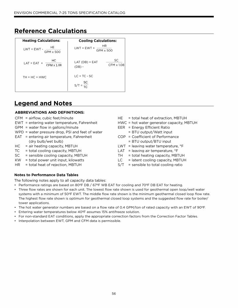
56
ENVISION COMMERCIAL 7-25 TONS SPECIFICATION CATALOG
Reference Calculations
Heating Calculations: Cooling Calculations:
LWT = EWT +
LAT (DB) = EAT
(DB) -
LC = TC - SC
S/T =
HR
GPM x 500
SC
CFM x 1.08
SCTC
LWT = EWT -
LAT = EAT +
TH = HC + HWC
HE
GPM x 500
HCCFM x 1.08
Legend and NotesgABBREVIATIONS AND DEFINITIONS:
CFM = airflow, cubic feet/minuteEWT = entering water temperature, FahrenheitGPM = water flow in gallons/minuteWPD = water pressure drop, PSI and feet of waterEAT = entering air temperature, Fahrenheit (dry bulb/wet bulb)HC = air heating capacity, MBTUHTC = total cooling capacity, MBTUHSC = sensible cooling capacity, MBTUHKW = total power unit input, kilowattsHR = total heat of rejection, MBTUH
HE = total heat of extraction, MBTUHHWC = hot water generator capacity, MBTUHEER = Energy Efficient Ratio = BTU output/Watt inputCOP = Coefficient of Performance = BTU output/BTU inputLWT = leaving water temperature, °FLAT = leaving air temperature, °FTH = total heating capacity, MBTUHLC = latent cooling capacity, MBTUHS/T = sensible to total cooling ratio
Notes to Performance Data Tables
The following notes apply to all capacity data tables:• Performance ratings are based on 80ºF DB / 67ºF WB EAT for cooling and 70ºF DB EAT for heating.
• Three flow rates are shown for each unit. The lowest flow rate shown is used for geothermal open loop/well water
systems with a minimum of 50ºF EWT. The middle flow rate shown is the minimum geothermal closed loop flow rate.
The highest flow rate shown is optimum for geothermal closed loop systems and the suggested flow rate for boiler/
tower applications.
• The hot water generator numbers are based on a flow rate of 0.4 GPM/ton of rated capacity with an EWT of 90ºF.
• Entering water temperatures below 40ºF assumes 15% antifreeze solution.
• For non-standard EAT conditions, apply the appropriate correction factors from the Correction Factor Tables.
• Interpolation between EWT, GPM and CFM data is permissible.

57
ENVISION COMMERCIAL 7-25 TONS SPECIFICATION CATALOG
Correction Factor TablesAir Flow Corrections (Dual Circuit)
Airflow Cooling Heating
CFM Per Tonof Clg
% of Nominal Total Cap Sens Cap Power Heat of Rej Htg Cap Power Heat of Ext
281 75% 0.981 0.910 0.956 0.976 0.956 1.049 0.947
299 80% 0.985 0.928 0.965 0.981 0.970 1.034 0.959
318 85% 0.988 0.947 0.975 0.986 0.977 1.027 0.968
337 90% 0.990 0.965 0.990 0.990 0.985 1.021 0.977
355 95% 0.996 0.985 0.995 0.997 0.992 1.014 0.986
374 100% 1.000 1.000 1.000 1.000 1.000 1.000 1.000
393 105% 1.005 1.030 1.012 1.014 1.010 0.993 1.005
412 110% 1.007 1.044 1.025 1.013 1.014 0.991 1.014
430 115% 1.010 1.065 1.035 1.018 1.021 0.987 1.024
449 120% 1.014 1.086 1.046 1.024 1.029 0.981 1.033
468 125% 1.017 1.106 1.059 1.027 1.040 0.980 1.039
07/25/07
Heating Capacity Corrections
Ent Air DB °FHeating Corrections
Htg Cap Power Heat of Ext
45 1.062 0.739 1.158
50 1.050 0.790 1.130
55 1.037 0.842 1.096
60 1.025 0.893 1.064
65 1.012 0.945 1.030
68 1.005 0.976 1.012
70 1.000 1.000 1.000
75 0.987 1.048 0.970
80 0.975 1.099 0.930
11/10/09
Cooling Capacity CorrectionsEntering
Air WB ºFTotal
Clg CapSensible Cooling Capacity Multipliers - Entering DB ºF Power
InputHeat of
Rejection60 65 70 75 80 80.6 85 90 95 100
55 0.898 0.723 0.866 1.048 1.185 * * * * * * 0.985 0.913
60 0.912 0.632 0.880 1.078 1.244 1.260 * * * * 0.994 0.927
65 0.967 0.694 0.881 1.079 1.085 1.270 * * * 0.997 0.972
66.2 0.983 0.655 0.842 1.040 1.060 1.232 * * * 0.999 0.986
67 1.000 0.616 0.806 1.000 1.023 1.193 1.330 * * 1.000 1.000
70 1.053 0.693 0.879 0.900 1.075 1.250 1.404 * 1.003 1.044
75 1.168 0.687 0.715 0.875 1.040 1.261 1.476 1.007 1.141
11/10/09NOTE: *Sensible capacity equals total capacity at conditions shown.

58
ENVISION COMMERCIAL 7-25 TONS SPECIFICATION CATALOG
Pressure Dropp
30°F 50°F 70°F 90°F 110°F10.0 2.48 2.36 2.29 2.21 2.14
080 16.0 5.96 5.62 5.22 4.89 4.6922.0 10.91 10.38 9.73 9.12 8.50
12.0 2.22 2.00 1.92 1.83 1.67095 18.0 4.62 4.02 3.80 3.75 3.65
24.0 7.31 6.81 5.80 5.60 5.19
16.0 2.03 1.93 1.88 1.80 1.50120 22.0 3.69 3.58 3.40 3.19 2.99
28.0 5.58 5.50 5.32 5.00 4.84
20.0 1.20 1.19 1.18 1.17 1.16160 28.0 2.64 2.50 2.37 2.24 2.12
35.0 3.72 3.65 3.41 3.36 3.21
22.0 1.50 1.50 1.50 1.50 1.50180 34.0 3.95 3.90 3.85 3.80 3.75
45.0 6.40 6.10 6.00 5.80 5.70
30.0 0.90 0.82 0.75 0.69 0.63240 45.0 2.22 2.06 1.91 1.77 1.64
60.0 3.47 3.29 3.06 2.88 2.40
35.0 1.84 1.60 1.39 1.21 1.05300 56.0 4.09 3.88 3.69 3.51 3.33
75.0 6.10 5.95 5.77 5.45 5.10
Model GPM Pressure Drop (psi)
Operating Limitsp g
Operating LimitsCooling Heating
(°F) (°C) (°F) (°C)
Air Limits
Min. Ambient Air 45 7.2 45 7.2
Rated Ambient Air 80 26.7 70 21.1
Max. Ambient Air 100 37.8 85 29.4
Min. Entering Air 50 10.0 40 4.4
Rated Entering Air db/wb 80.6/66.2 27/19 68 20.0
Max. Entering Air db/wb 110/83 43/28.3 80 26.7
Water Limits
Min. Entering Water 30 -1.1 20 -6.7
Normal Entering Water 50-110 10-43.3 30-70 -1.1
Max. Entering Water 120 48.9 90 32.2
NOTE: Minimum/maximum limits are only for start-up conditions, andare meant for bringing the space up to occupancy temperature. Units are not designed to operate at the minimum/maximum conditions on a regular basis. The operating limits are dependant upon three primary factors: 1) water temperature, 2) return air temperature, and 3) ambienttemperature. When any of the factors are at the minimum or maximumlevels, the other two factors must be at the normal level for proper and reliable unit operation.
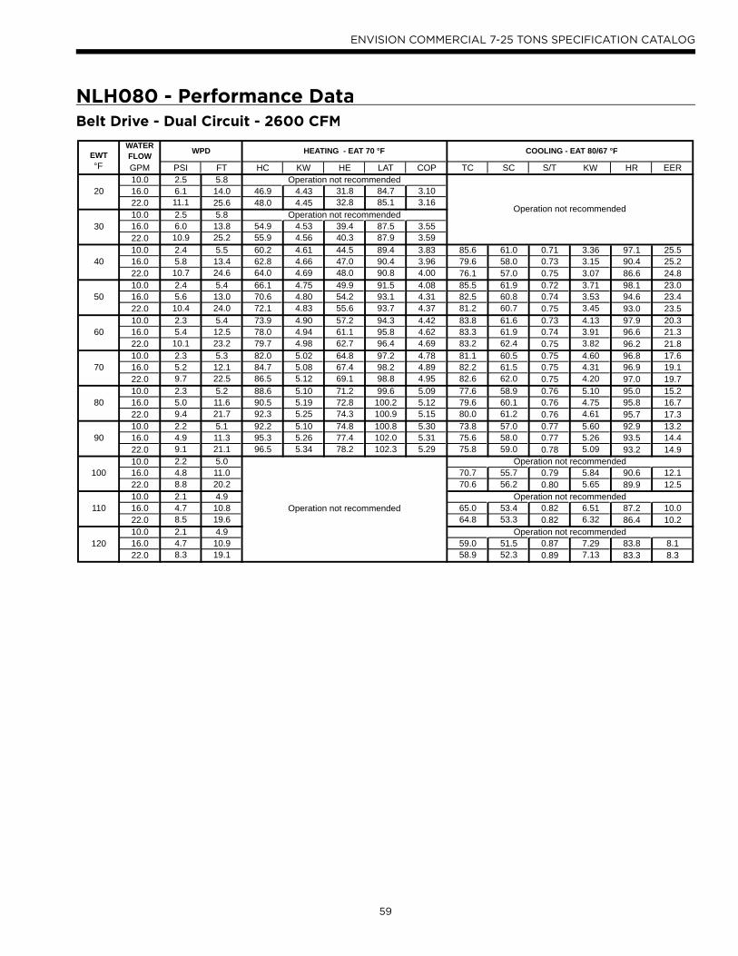
59
ENVISION COMMERCIAL 7-25 TONS SPECIFICATION CATALOG
Belt Drive - Dual Circuit - 2600 CFM
NLH080 - Performance Data
EWTWATER FLOW
°F GPM PSI FT HC KW HE LAT COP TC SC S/T KW HR EER10.0 2.5 5.8
20 16.0 6.1 14.0 46.9 4.43 31.8 84.7 3.1022.0 11.1 25.6 48.0 4.45 32.8 85.1 3.1610.0 2.5 5.8
30 16.0 6.0 13.8 54.9 4.53 39.4 87.5 3.5522.0 10.9 25.2 55.9 4.56 40.3 87.9 3.5910.0 2.4 5.5 60.2 4.61 44.5 89.4 3.83 85.6 61.0 0.71 3.36 97.1 25.5
40 16.0 5.8 13.4 62.8 4.66 47.0 90.4 3.96 79.6 58.0 0.73 3.15 90.4 25.222.0 10.7 24.6 64.0 4.69 48.0 90.8 4.00 76.1 57.0 0.75 3.07 86.6 24.810.0 2.4 5.4 66.1 4.75 49.9 91.5 4.08 85.5 61.9 0.72 3.71 98.1 23.0
50 16.0 5.6 13.0 70.6 4.80 54.2 93.1 4.31 82.5 60.8 0.74 3.53 94.6 23.422.0 10.4 24.0 72.1 4.83 55.6 93.7 4.37 81.2 60.7 0.75 3.45 93.0 23.510.0 2.3 5.4 73.9 4.90 57.2 94.3 4.42 83.8 61.6 0.73 4.13 97.9 20.3
60 16.0 5.4 12.5 78.0 4.94 61.1 95.8 4.62 83.3 61.9 0.74 3.91 96.6 21.322.0 10.1 23.2 79.7 4.98 62.7 96.4 4.69 83.2 62.4 0.75 3.82 96.2 21.810.0 2.3 5.3 82.0 5.02 64.8 97.2 4.78 81.1 60.5 0.75 4.60 96.8 17.6
70 16.0 5.2 12.1 84.7 5.08 67.4 98.2 4.89 82.2 61.5 0.75 4.31 96.9 19.122.0 9.7 22.5 86.5 5.12 69.1 98.8 4.95 82.6 62.0 0.75 4.20 97.0 19.710.0 2.3 5.2 88.6 5.10 71.2 99.6 5.09 77.6 58.9 0.76 5.10 95.0 15.2
80 16.0 5.0 11.6 90.5 5.19 72.8 100.2 5.12 79.6 60.1 0.76 4.75 95.8 16.722.0 9.4 21.7 92.3 5.25 74.3 100.9 5.15 80.0 61.2 0.76 4.61 95.7 17.310.0 2.2 5.1 92.2 5.10 74.8 100.8 5.30 73.8 57.0 0.77 5.60 92.9 13.2
90 16.0 4.9 11.3 95.3 5.26 77.4 102.0 5.31 75.6 58.0 0.77 5.26 93.5 14.422.0 9.1 21.1 96.5 5.34 78.2 102.3 5.29 75.8 59.0 0.78 5.09 93.2 14.910.0 2.2 5.0
100 16.0 4.8 11.0 70.7 55.7 0.79 5.84 90.6 12.122.0 8.8 20.2 70.6 56.2 0.80 5.65 89.9 12.510.0 2.1 4.9
110 16.0 4.7 10.8 65.0 53.4 0.82 6.51 87.2 10.022.0 8.5 19.6 64.8 53.3 0.82 6.32 86.4 10.210.0 2.1 4.9
120 16.0 4.7 10.9 59.0 51.5 0.87 7.29 83.8 8.122.0 8.3 19.1 58.9 52.3 0.89 7.13 83.3 8.3
WPD HEATING - EAT 70 °F
Operation not recommended
Operation not recommended
Operation not recommended
Operation not recommended
Operation not recommended
Operation not recommended
COOLING - EAT 80/67 °F
Operation not recommended

60
ENVISION COMMERCIAL 7-25 TONS SPECIFICATION CATALOG
Belt Drive - Dual Circuit - 3200 CFM
NLH095 - Performance Data
EWT WATER FLOW
°F GPM PSI FT HC KW HE LAT COP TC SC S/T KW HR EER12.0 2.1 4.9
20 18.0 5.1 11.9 55.2 5.46 36.6 84.0 2.9624.0 7.2 16.6 56.8 5.52 38.0 84.4 3.0212.0 2.1 4.9
30 18.0 4.6 10.7 71.6 5.57 52.6 88.7 3.7724.0 7.1 16.5 73.3 5.66 54.0 89.2 3.7912.0 2.0 4.7 74.5 5.57 55.5 89.6 3.92 97.0 74.0 0.76 4.33 111.8 22.4
40 18.0 4.3 9.8 82.6 5.70 63.2 91.9 4.25 93.5 72.5 0.78 4.05 107.3 23.124.0 7.0 16.2 84.3 5.81 64.5 92.4 4.25 90.0 71.4 0.79 3.87 103.2 23.312.0 2.0 4.7 79.5 5.71 60.0 91.0 4.08 98.7 73.5 0.74 4.63 114.5 21.3
50 18.0 4.0 9.3 89.6 5.83 69.7 93.9 4.50 99.6 71.1 0.71 4.27 114.2 23.324.0 6.8 15.6 91.3 5.96 71.0 94.4 4.49 94.3 70.4 0.75 4.28 108.9 22.012.0 2.0 4.5 85.6 5.84 65.7 92.8 4.30 97.8 72.5 0.74 5.05 90.8 19.4
60 18.0 3.9 9.0 94.1 5.97 73.8 95.2 4.62 101.3 70.0 0.69 4.64 117.1 21.824.0 6.5 14.9 95.9 6.09 75.1 95.7 4.61 95.8 69.7 0.73 4.71 111.9 20.312.0 1.9 4.4 92.3 5.96 72.0 94.7 4.54 94.9 71.2 0.75 5.56 113.9 17.1
70 18.0 3.8 8.8 97.7 6.09 77.0 96.3 4.71 99.5 69.0 0.69 5.14 117.1 19.424.0 6.1 14.2 99.5 6.21 78.3 96.8 4.70 94.9 69.3 0.73 5.18 112.6 18.312.0 1.8 4.2 98.7 6.06 78.0 96.6 4.78 90.7 69.6 0.77 6.12 111.5 14.8
80 18.0 3.8 8.7 102.0 6.19 80.8 97.5 4.83 95.1 68.0 0.72 5.75 114.7 16.624.0 5.8 13.4 103.7 6.31 82.2 98.0 4.82 92.1 68.5 0.74 5.69 111.5 16.212.0 1.7 4.0 104.0 6.12 83.1 98.1 4.98 85.8 68.0 0.79 6.70 108.6 12.8
90 18.0 3.8 8.7 108.3 6.26 87.0 99.3 5.07 88.9 67.0 0.75 6.43 110.9 13.824.0 5.5 12.7 110.0 6.37 88.3 99.8 5.06 87.7 67.8 0.77 6.26 109.1 14.012.0 1.7 3.9
100 18.0 3.7 8.6 81.9 65.8 0.80 7.16 106.3 11.424.0 5.3 12.3 82.2 67.0 0.81 6.91 105.7 11.912.0 1.7 3.9
110 18.0 3.6 8.4 74.9 64.4 0.86 7.93 101.9 9.424.0 5.2 12.0 75.9 65.9 0.87 7.65 102.0 9.912.0 1.7 3.9
120 18.0 3.5 8.1 68.8 62.6 0.91 8.69 98.4 7.924.0 5.2 12.0 69.2 63.3 0.91 8.49 98.2 8.2
WPD HEATING - EAT 70 °F
Operation not recommended
Operation not recommended
Operation not recommended
Operation not recommended
Operation not recommended
COOLING - EAT 80/67 °F
Operation not recommended
Operation not recommended

61
ENVISION COMMERCIAL 7-25 TONS SPECIFICATION CATALOG
Belt Drive - Dual Circuit - 3600 CFM
NLH120 - Performance Data
EWT WATER FLOW
°F GPM PSI FT HC KW HE LAT COP TC SC S/T KW HR EER16.0 2.7 6.2
20 22.0 4.2 9.7 74.2 6.13 53.3 87.1 3.5528.0 6.4 14.8 75.7 6.13 54.8 87.5 3.6216.0 2.6 6.0
30 22.0 4.1 9.4 88.0 6.25 66.7 90.6 4.1328.0 6.2 14.3 90.1 6.21 68.9 91.2 4.2516.0 2.5 5.7 97.5 6.41 75.6 93.1 4.46 136.3 85.6 0.63 5.50 155.1 24.8
40 22.0 4.0 9.1 100.9 6.39 79.0 93.9 4.62 131.8 84.8 0.64 5.74 151.4 23.028.0 6.0 13.8 102.8 6.39 81.0 94.4 4.72 129.7 84.0 0.65 5.82 149.6 22.316.0 2.4 5.6 106.7 6.55 84.4 95.5 4.78 133.6 84.0 0.63 6.36 155.3 21.0
50 22.0 3.9 8.9 113.2 6.56 90.9 97.1 5.06 133.0 83.7 0.63 6.34 154.6 21.028.0 5.8 13.4 114.8 6.62 92.3 97.5 5.08 133.4 83.9 0.63 6.29 154.8 21.216.0 2.3 5.3 119.6 6.69 96.8 98.8 5.24 129.0 82.1 0.64 7.22 153.6 17.9
60 22.0 3.8 8.7 125.8 6.73 102.8 100.4 5.48 130.9 82.5 0.63 6.97 154.7 18.828.0 5.7 13.1 127.2 6.86 103.7 100.7 5.43 132.0 83.3 0.63 6.84 155.3 19.316.0 2.2 5.0 134.2 6.82 111.0 102.5 5.77 123.3 80.0 0.65 8.07 150.8 15.3
70 22.0 3.7 8.5 139.0 6.88 115.6 103.8 5.92 126.4 81.0 0.64 7.66 152.5 16.528.0 5.5 12.7 140.8 7.07 116.7 104.2 5.84 126.9 82.0 0.65 7.48 152.4 17.016.0 2.0 4.6 148.8 6.94 125.1 106.3 6.28 117.0 77.7 0.66 8.90 147.4 13.1
80 22.0 3.5 8.2 153.6 7.01 129.7 107.5 6.43 120.0 79.2 0.66 8.43 148.8 14.228.0 5.4 12.4 156.7 7.20 132.2 108.3 6.38 119.4 80.3 0.67 8.22 147.4 14.516.0 1.8 4.2 161.5 7.07 137.4 109.5 6.70 110.8 75.5 0.68 9.71 143.9 11.4
90 22.0 3.4 7.8 170.0 7.09 145.8 111.7 7.03 112.6 77.0 0.68 9.29 144.3 12.128.0 5.2 12.0 176.0 7.20 151.4 113.3 7.16 110.8 78.0 0.70 9.06 141.7 12.216.0 1.6 3.8
100 22.0 3.2 7.4 104.9 74.4 0.71 10.25 139.8 10.228.0 5.0 11.6 102.5 75.2 0.73 10.02 136.7 10.216.0 1.5 3.5
110 22.0 3.0 6.9 97.5 71.2 0.73 11.34 136.2 8.628.0 4.8 11.2 95.8 71.8 0.75 11.10 133.7 8.616.0 1.5 3.5
120 22.0 2.7 6.3 91.3 67.5 0.74 12.56 134.2 7.328.0 4.6 10.6 92.0 68.2 0.74 12.31 134.0 7.5
WPD HEATING - EAT 70 °F
Operation not recommended
COOLING - EAT 80/67 °F
Operation not recommended
Operation not recommended
Operation not recommended
Operation not recommended
Operation not recommendedOperation not recommended
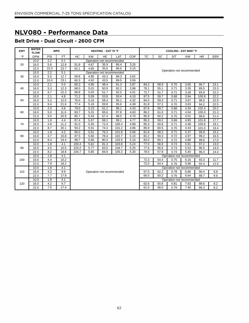
62
ENVISION COMMERCIAL 7-25 TONS SPECIFICATION CATALOG
Belt Drive - Dual Circuit - 2600 CFM
NLV080 - Performance Data
EWT WATER FLOW
°F GPM PSI FT HC KW HE LAT COP TC SC S/T KW HR EER10.0 2.2 5.1
20 16.0 5.6 12.9 51.8 4.67 35.9 86.4 3.2522.0 10.3 23.7 52.1 4.85 35.6 86.6 3.1510.0 2.2 5.1
30 16.0 5.5 12.7 59.8 4.85 43.3 89.3 3.6222.0 10.0 23.1 60.3 4.92 43.5 89.5 3.5910.0 2.1 5.0 65.3 4.95 48.4 91.3 3.87 84.2 58.9 0.70 3.65 96.7 23.1
40 16.0 5.3 12.3 68.0 5.01 50.9 92.2 3.98 78.1 55.1 0.71 3.35 89.5 23.322.0 9.7 22.3 68.8 5.03 51.7 92.5 4.01 72.7 51.7 0.71 3.28 83.9 22.210.0 2.1 4.8 71.2 5.09 53.8 93.4 4.10 87.5 59.7 0.68 3.94 100.9 22.2
50 16.0 5.2 12.0 76.0 5.16 58.4 95.1 4.32 84.0 59.3 0.71 3.67 96.5 22.922.0 9.4 21.6 77.4 5.18 59.8 95.6 4.38 81.8 57.2 0.70 3.63 94.2 22.510.0 2.0 4.6 79.0 5.23 61.2 96.1 4.43 87.6 59.7 0.68 4.34 102.4 20.2
60 16.0 5.0 11.6 83.7 5.31 65.6 97.8 4.63 86.2 61.0 0.71 4.04 100.0 21.322.0 9.0 20.9 85.7 5.34 67.4 98.5 4.70 85.9 60.2 0.70 4.01 99.6 21.410.0 1.9 4.4 87.4 5.37 69.1 99.1 4.77 85.3 59.2 0.69 4.83 101.8 17.7
70 16.0 4.9 11.2 91.0 5.45 72.4 100.4 4.89 85.3 60.8 0.71 4.48 100.6 19.122.0 8.7 20.1 93.2 5.51 74.4 101.2 4.96 85.9 60.5 0.70 4.43 101.0 19.410.0 1.8 4.2 95.0 5.51 76.2 101.8 5.06 81.6 58.2 0.71 5.37 99.9 15.2
80 16.0 4.7 10.8 97.5 5.60 78.4 102.7 5.10 82.2 59.3 0.72 4.97 99.2 16.522.0 8.4 19.4 99.7 5.66 80.3 103.5 5.16 83.0 60.1 0.72 4.88 99.6 17.010.0 1.8 4.1 100.4 5.62 81.3 103.8 5.24 77.0 56.9 0.74 5.91 97.2 13.0
90 16.0 4.5 10.5 103.2 5.77 83.5 104.7 5.25 77.6 56.9 0.73 5.53 96.5 14.022.0 8.2 18.8 104.7 5.80 84.9 105.3 5.30 78.0 57.8 0.74 5.40 96.4 14.410.0 1.8 4.1
100 16.0 4.4 10.2 72.3 54.4 0.75 6.16 93.3 11.722.0 7.9 18.2 72.0 54.4 0.76 5.98 92.4 12.010.0 1.8 4.1
110 16.0 4.3 9.9 67.0 52.2 0.78 6.86 90.4 9.822.0 7.7 17.8 66.0 50.2 0.76 6.64 88.7 9.910.0 1.8 4.1
120 16.0 4.2 9.7 62.6 50.8 0.81 7.63 88.6 8.222.0 7.5 17.4 61.0 48.0 0.79 7.40 86.3 8.2
WPD HEATING - EAT 70 °F
Operation not recommended
Operation not recommended
Operation not recommended
Operation not recommended
COOLING - EAT 80/67 °F
Operation not recommended
Operation not recommended
Operation not recommended

63
ENVISION COMMERCIAL 7-25 TONS SPECIFICATION CATALOG
NLV095 - Performance Data
EWT WATER FLOW
°F GPM PSI FT HC KW HE LAT COP TC SC S/T KW HR EER12.0 2.2 5.1
20 18.0 4.7 10.9 56.8 5.42 38.3 86.8 3.0724.0 8.0 18.6 57.8 5.47 39.1 87.1 3.1012.0 2.1 4.9
30 18.0 4.7 10.9 66.4 5.60 47.3 89.9 3.4724.0 8.0 18.5 67.5 5.61 48.4 90.3 3.5312.0 2.0 4.6 73.5 5.72 54.0 92.3 3.77 101.6 70.9 0.70 4.14 115.8 24.5
40 18.0 4.6 10.7 76.4 5.78 56.7 93.3 3.88 97.5 66.1 0.68 3.80 110.4 25.724.0 7.8 18.1 77.9 5.77 58.2 93.8 3.96 93.6 62.7 0.67 3.71 106.3 25.212.0 2.0 4.7 80.9 5.88 60.9 94.8 4.03 101.1 70.5 0.70 4.44 116.2 22.8
50 18.0 4.4 10.3 86.5 5.95 66.2 96.6 4.26 98.6 68.1 0.69 4.19 112.9 23.524.0 7.6 17.6 88.3 5.95 68.0 97.2 4.35 96.2 65.6 0.68 4.06 110.1 23.712.0 2.0 4.6 91.0 6.06 70.3 98.1 4.40 98.8 69.8 0.71 4.89 115.5 20.2
60 18.0 4.2 9.8 96.4 6.13 75.5 99.9 4.61 97.8 68.8 0.70 4.62 113.6 21.224.0 7.3 16.9 98.5 6.14 77.5 100.6 4.70 97.1 67.5 0.69 4.48 112.4 21.712.0 1.9 4.5 101.7 6.24 80.4 101.6 4.78 95.2 68.8 0.72 5.46 113.8 17.4
70 18.0 4.0 9.3 105.7 6.30 84.2 102.9 4.91 95.4 68.4 0.72 5.10 112.8 18.724.0 7.0 16.2 107.9 6.33 86.3 103.7 4.99 96.4 68.1 0.71 4.96 113.3 19.412.0 1.9 4.3 111.4 6.41 89.5 104.8 5.10 90.8 67.6 0.74 6.08 111.6 14.9
80 18.0 3.8 8.9 114.0 6.48 91.9 105.7 5.16 91.9 67.3 0.73 5.65 111.1 16.324.0 6.7 15.5 116.1 6.52 93.9 106.4 5.22 94.2 68.3 0.72 5.50 113.0 17.112.0 1.8 4.1 118.0 6.56 95.6 107.0 5.28 86.2 66.2 0.77 6.69 109.0 12.9
90 18.0 3.7 8.5 121.0 6.65 98.3 108.0 5.33 87.5 65.5 0.75 6.26 108.9 14.024.0 6.5 15.0 122.7 6.69 99.9 108.6 5.38 90.8 67.4 0.74 6.10 111.6 14.912.0 1.7 4.0
100 18.0 3.6 8.3 82.8 63.4 0.77 6.95 106.5 11.924.0 6.3 14.5 86.3 65.8 0.76 6.76 109.4 12.812.0 1.7 3.8
110 18.0 3.6 8.3 78.0 61.3 0.79 7.73 104.4 10.124.0 6.2 14.2 80.8 63.5 0.79 7.48 106.4 10.812.0 1.6 3.7
120 18.0 3.7 8.5 73.6 59.4 0.81 8.60 103.0 8.624.0 6.2 14.3 74.6 61.4 0.82 8.26 102.8 9.0
WPD HEATING - EAT 70 °F
Operation not recommended
Operation not recommended
COOLING - EAT 80/67 °F
Operation not recommended
Operation not recommended
Operation not recommended
Operation not recommended
Operation not recommended
Belt Drive - Dual Circuit - 2800 CFM

64
ENVISION COMMERCIAL 7-25 TONS SPECIFICATION CATALOG
NLV120 - Performance Data
EWT WATER FLOW
°F GPM PSI FT HC KW HE LAT COP TC SC S/T KW HR EER16.0 2.1 4.9
20 22.0 4.0 9.2 69.6 7.41 44.3 85.9 2.7528.0 5.8 13.4 72.1 7.42 46.8 86.5 2.8516.0 2.1 4.9
30 22.0 3.8 8.8 82.3 7.60 56.4 89.2 3.1728.0 5.7 13.1 84.2 7.61 58.3 89.7 3.2416.0 2.0 4.7 92.6 7.69 66.4 91.8 3.53 140.9 100.0 0.71 6.04 161.5 23.3
40 22.0 3.7 8.5 96.3 7.83 69.5 92.8 3.60 138.5 99.0 0.71 5.75 158.1 24.128.0 5.6 12.9 98.0 7.86 71.2 93.2 3.66 137.2 98.0 0.71 5.59 156.3 24.516.0 1.9 4.5 103.4 7.94 76.3 94.6 3.82 136.9 97.3 0.71 6.47 158.9 21.2
50 22.0 3.6 8.3 110.8 8.10 83.2 96.5 4.01 137.0 97.8 0.71 6.24 158.3 22.028.0 5.5 12.7 112.8 8.14 85.0 97.0 4.06 135.5 97.1 0.72 6.07 156.2 22.316.0 1.9 4.4 118.3 8.24 90.1 98.4 4.21 130.9 94.2 0.72 7.08 155.1 18.5
60 22.0 3.5 8.1 125.4 8.39 96.8 100.3 4.38 132.8 95.6 0.72 6.81 156.0 19.528.0 5.4 12.5 128.0 8.45 99.2 100.9 4.44 131.6 95.5 0.73 6.63 154.2 19.916.0 1.9 4.3 134.2 8.58 104.9 102.5 4.58 123.7 90.8 0.73 7.83 150.4 15.8
70 22.0 3.4 7.9 139.6 8.71 109.8 103.9 4.70 126.6 92.5 0.73 7.47 152.1 16.928.0 5.3 12.3 142.9 8.78 113.0 104.8 4.77 126.1 93.0 0.74 7.27 150.8 17.316.0 1.9 4.3 148.2 8.95 117.6 106.1 4.85 116.1 87.3 0.75 8.65 145.6 13.4
80 22.0 3.3 7.6 152.6 9.05 121.7 107.2 4.94 119.1 88.9 0.75 8.22 147.1 14.528.0 5.2 12.0 157.0 9.12 125.9 108.4 5.04 119.3 90.4 0.76 8.00 146.6 14.916.0 1.8 4.2 157.2 9.36 125.3 108.4 4.92 108.7 83.9 0.77 9.48 141.1 11.5
90 22.0 3.2 7.4 164.0 9.41 131.9 110.2 5.11 111.0 85.0 0.77 9.07 142.0 12.228.0 5.0 11.6 169.5 9.47 137.2 111.6 5.25 112.0 87.0 0.78 8.83 142.1 12.716.0 1.7 3.9
100 22.0 3.1 7.1 103.1 81.1 0.79 10.02 137.2 10.328.0 4.8 11.1 104.5 83.1 0.79 9.77 137.9 10.716.0 1.4 3.3
110 22.0 2.9 6.7 95.9 77.3 0.81 11.07 133.7 8.728.0 4.5 10.4 97.5 78.7 0.81 10.81 134.4 9.016.0 1.4 3.3
120 22.0 2.7 6.2 90.4 74.1 0.82 12.23 132.1 7.428.0 4.1 9.5 91.3 75.0 0.82 11.98 132.2 7.6
WPD HEATING - EAT 70 °F
Operation not recommended
Operation not recommended
Operation not recommended
Operation not recommended
COOLING - EAT 80/67 °F
Operation not recommended
Operation not recommended
Operation not recommended
Belt Drive - Dual Circuit - 3600 CFM
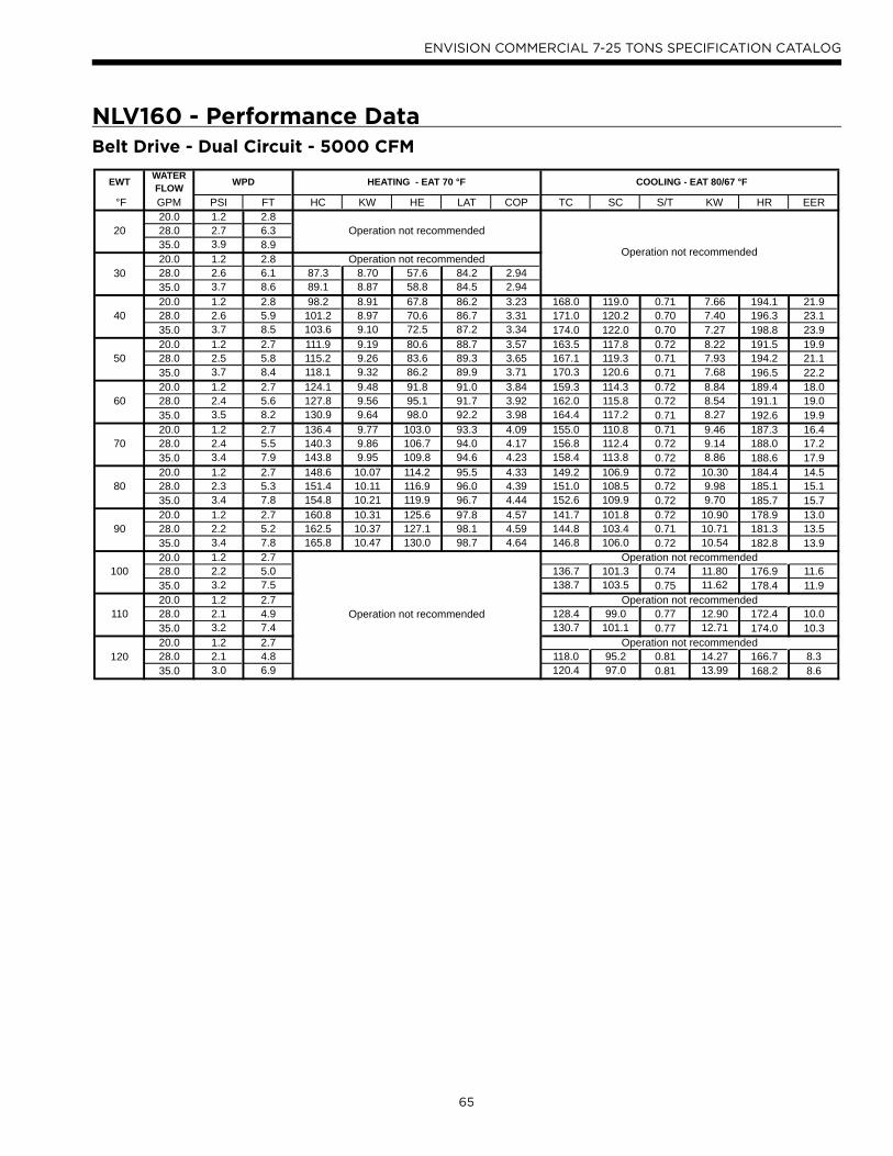
65
ENVISION COMMERCIAL 7-25 TONS SPECIFICATION CATALOG
NLV160 - Performance Data
EWT WATER FLOW
°F GPM PSI FT HC KW HE LAT COP TC SC S/T KW HR EER20.0 1.2 2.8
20 28.0 2.7 6.335.0 3.9 8.920.0 1.2 2.8
30 28.0 2.6 6.1 87.3 8.70 57.6 84.2 2.9435.0 3.7 8.6 89.1 8.87 58.8 84.5 2.9420.0 1.2 2.8 98.2 8.91 67.8 86.2 3.23 168.0 119.0 0.71 7.66 194.1 21.9
40 28.0 2.6 5.9 101.2 8.97 70.6 86.7 3.31 171.0 120.2 0.70 7.40 196.3 23.135.0 3.7 8.5 103.6 9.10 72.5 87.2 3.34 174.0 122.0 0.70 7.27 198.8 23.920.0 1.2 2.7 111.9 9.19 80.6 88.7 3.57 163.5 117.8 0.72 8.22 191.5 19.9
50 28.0 2.5 5.8 115.2 9.26 83.6 89.3 3.65 167.1 119.3 0.71 7.93 194.2 21.135.0 3.7 8.4 118.1 9.32 86.2 89.9 3.71 170.3 120.6 0.71 7.68 196.5 22.220.0 1.2 2.7 124.1 9.48 91.8 91.0 3.84 159.3 114.3 0.72 8.84 189.4 18.0
60 28.0 2.4 5.6 127.8 9.56 95.1 91.7 3.92 162.0 115.8 0.72 8.54 191.1 19.035.0 3.5 8.2 130.9 9.64 98.0 92.2 3.98 164.4 117.2 0.71 8.27 192.6 19.920.0 1.2 2.7 136.4 9.77 103.0 93.3 4.09 155.0 110.8 0.71 9.46 187.3 16.4
70 28.0 2.4 5.5 140.3 9.86 106.7 94.0 4.17 156.8 112.4 0.72 9.14 188.0 17.235.0 3.4 7.9 143.8 9.95 109.8 94.6 4.23 158.4 113.8 0.72 8.86 188.6 17.920.0 1.2 2.7 148.6 10.07 114.2 95.5 4.33 149.2 106.9 0.72 10.30 184.4 14.5
80 28.0 2.3 5.3 151.4 10.11 116.9 96.0 4.39 151.0 108.5 0.72 9.98 185.1 15.135.0 3.4 7.8 154.8 10.21 119.9 96.7 4.44 152.6 109.9 0.72 9.70 185.7 15.720.0 1.2 2.7 160.8 10.31 125.6 97.8 4.57 141.7 101.8 0.72 10.90 178.9 13.0
90 28.0 2.2 5.2 162.5 10.37 127.1 98.1 4.59 144.8 103.4 0.71 10.71 181.3 13.535.0 3.4 7.8 165.8 10.47 130.0 98.7 4.64 146.8 106.0 0.72 10.54 182.8 13.920.0 1.2 2.7
100 28.0 2.2 5.0 136.7 101.3 0.74 11.80 176.9 11.635.0 3.2 7.5 138.7 103.5 0.75 11.62 178.4 11.920.0 1.2 2.7
110 28.0 2.1 4.9 128.4 99.0 0.77 12.90 172.4 10.035.0 3.2 7.4 130.7 101.1 0.77 12.71 174.0 10.320.0 1.2 2.7
120 28.0 2.1 4.8 118.0 95.2 0.81 14.27 166.7 8.335.0 3.0 6.9 120.4 97.0 0.81 13.99 168.2 8.6
WPD HEATING - EAT 70 °F
Operation not recommended
Operation not recommended
Operation not recommended
Operation not recommended
Operation not recommended
COOLING - EAT 80/67 °F
Operation not recommendedOperation not recommended
Belt Drive - Dual Circuit - 5000 CFM

66
ENVISION COMMERCIAL 7-25 TONS SPECIFICATION CATALOG
NLV180 - Performance Data
EWT WATER FLOW
°F GPM PSI FT HC KW HE LAT COP TC SC S/T KW HR EER22.0 1.5 3.5
20 34.0 4.0 9.245.0 6.4 14.922.0 1.5 3.5
30 34.0 4.0 9.1 119.7 10.20 84.9 87.8 3.4445.0 6.4 14.8 123.0 10.33 87.8 88.3 3.4922.0 1.5 3.5 129.6 10.43 94.1 89.4 3.64 176.8 122.3 0.69 8.78 206.8 20.1
40 34.0 3.9 9.1 134.9 10.64 98.6 90.3 3.72 179.7 127.8 0.71 8.42 208.4 21.345.0 6.3 14.4 140.0 10.82 103.1 91.1 3.79 182.8 129.7 0.71 8.03 210.2 22.822.0 1.5 3.5 146.0 10.89 108.8 92.1 3.93 172.5 121.3 0.70 9.49 204.9 18.2
50 34.0 3.9 9.0 151.7 11.10 113.9 93.1 4.01 175.7 124.7 0.71 9.11 206.8 19.345.0 6.1 14.1 157.0 11.30 118.4 94.0 4.07 178.7 127.8 0.72 8.77 208.6 20.422.0 1.5 3.5 166.1 11.39 127.2 95.5 4.27 168.4 120.3 0.71 10.30 203.5 16.3
60 34.0 3.9 8.9 172.3 11.60 132.7 96.5 4.35 172.1 123.2 0.72 9.91 205.9 17.445.0 6.1 14.0 178.0 11.79 137.8 97.4 4.42 175.4 125.8 0.72 9.55 208.0 18.422.0 1.5 3.5 186.1 11.89 145.5 98.8 4.59 164.3 119.3 0.73 11.11 202.2 14.8
70 34.0 3.8 8.9 192.8 12.09 151.6 99.9 4.67 168.4 121.6 0.72 10.70 204.9 15.745.0 6.0 13.9 199.0 12.28 157.1 100.9 4.75 172.1 123.8 0.72 10.33 207.3 16.722.0 1.5 3.5 210.6 12.43 168.2 102.8 4.97 161.0 117.6 0.73 11.98 201.9 13.4
80 34.0 3.8 8.8 217.9 12.62 174.8 104.0 5.06 165.1 119.9 0.73 11.57 204.5 14.345.0 5.9 13.6 224.0 12.79 180.4 105.0 5.13 168.8 122.1 0.72 11.20 207.0 15.122.0 1.5 3.5 237.8 12.99 193.5 107.3 5.37 159.7 115.5 0.72 13.02 204.1 12.3
90 34.0 3.8 8.8 245.6 13.18 200.7 108.6 5.46 163.2 117.3 0.72 12.54 206.0 13.045.0 5.8 13.4 249.0 13.30 203.6 109.2 5.49 165.5 120.3 0.73 12.06 206.6 13.722.0 1.5 3.5
100 34.0 3.8 8.7 159.2 115.7 0.73 13.63 205.7 11.745.0 5.7 13.2 161.7 118.4 0.73 13.23 206.8 12.222.0 1.5 3.5
110 34.0 3.7 8.7 155.1 114.0 0.73 14.78 205.5 10.545.0 5.7 13.2 157.8 116.4 0.74 14.40 206.9 11.022.0 1.5 3.5
120 34.0 3.7 8.6 151.9 112.8 0.74 16.01 206.5 9.545.0 5.6 12.9 155.0 115.0 0.74 15.75 208.7 9.8
Operation not recommended
Operation not recommended
Operation not recommended
COOLING - EAT 80/67 °F
Operation not recommended
Operation not recommended
WPD HEATING - EAT 70 °F
Operation not recommended
Operation not recommended
Belt Drive - Dual Circuit - 5600 CFM

67
ENVISION COMMERCIAL 7-25 TONS SPECIFICATION CATALOG
NLV240 - Performance Data
EWT WATER FLOW
°F GPM PSI FT HC KW HE LAT COP TC SC S/T KW HR EER30.0 0.9 2.2
20 45.0 2.3 5.360.0 3.7 8.630.0 0.9 2.1
30 45.0 2.2 5.1 178.9 10.81 142.0 89.8 4.8560.0 3.5 8.0 192.0 10.93 154.7 91.4 5.1530.0 0.9 2.0 192.4 11.12 154.5 91.4 5.07 267.0 178.0 0.67 9.13 298.1 29.3
40 45.0 2.1 4.9 200.6 11.22 162.3 92.4 5.24 268.7 182.7 0.68 8.82 298.8 30.560.0 3.4 7.8 212.9 11.35 174.1 93.9 5.50 273.3 185.5 0.68 8.73 303.1 31.330.0 0.8 1.9 215.1 11.51 175.9 94.2 5.48 266.3 180.4 0.68 9.69 299.4 27.5
50 45.0 2.1 4.7 224.4 11.64 184.7 95.3 5.65 268.2 182.2 0.68 9.39 300.2 28.660.0 3.3 7.6 233.7 11.78 193.5 96.5 5.82 270.0 184.0 0.68 9.08 301.0 29.730.0 0.8 1.8 242.6 11.92 201.9 97.6 5.96 258.2 175.7 0.68 10.32 293.4 25.0
60 45.0 2.0 4.6 253.3 12.10 212.0 98.9 6.14 260.3 177.8 0.68 10.02 294.5 26.060.0 3.2 7.3 264.0 12.27 222.1 100.2 6.31 262.4 180.0 0.69 9.72 295.5 27.030.0 0.8 1.7 270.1 12.34 228.0 100.9 6.42 250.2 171.0 0.68 10.94 287.5 22.9
70 45.0 1.9 4.4 282.2 12.55 239.4 102.4 6.59 252.4 173.5 0.69 10.65 288.8 23.760.0 3.1 7.1 294.3 12.77 250.8 103.9 6.76 254.7 175.9 0.69 10.35 290.0 24.630.0 0.7 1.7 303.3 12.77 259.7 104.9 6.96 235.4 168.2 0.71 11.67 275.3 20.2
80 45.0 1.8 4.2 317.2 13.03 272.7 106.6 7.13 237.7 170.7 0.72 11.38 276.5 20.960.0 3.0 6.9 327.2 13.22 282.0 107.9 7.25 240.0 173.2 0.72 11.08 277.8 21.730.0 0.7 1.6 339.8 13.22 294.7 109.4 7.53 217.3 163.6 0.75 12.36 259.5 17.6
90 45.0 1.8 4.1 355.6 13.53 309.5 111.3 7.70 222.0 166.1 0.75 12.12 263.4 18.360.0 2.9 6.7 360.0 13.68 313.3 111.9 7.71 225.2 170.4 0.76 11.81 265.5 19.130.0 0.7 1.5
100 45.0 1.7 3.9 209.2 160.0 0.76 12.87 253.1 16.360.0 2.7 6.3 212.4 163.6 0.77 12.84 256.2 16.530.0 0.6 1.4
110 45.0 1.6 3.8 196.1 153.4 0.78 13.70 242.9 14.360.0 2.4 5.5 199.5 156.7 0.79 13.86 246.8 14.430.0 0.6 1.4
120 45.0 1.6 3.6 182.1 147.2 0.81 14.59 231.9 12.560.0 2.4 5.5 185.9 150.0 0.81 14.91 236.7 12.5
Operation not recommended
Operation not recommended
Operation not recommended
COOLING - EAT 80/67 °F
Operation not recommended
Operation not recommended
Operation not recommended
WPD HEATING - EAT 70 °F
Operation not recommended
Belt Drive - Dual Circuit - 7600 CFM

68
ENVISION COMMERCIAL 7-25 TONS SPECIFICATION CATALOG
NLV300 - Performance Data
EWT WATER FLOW
°F GPM PSI FT HC KW HE LAT COP TC SC S/T KW HR EER35.0 2.0 4.6
20 56.0 4.2 9.775.0 6.3 14.735.0 1.8 4.3
30 56.0 4.1 9.4 218.4 17.07 160.2 89.3 3.7575.0 6.1 14.1 225.0 17.15 166.5 89.9 3.8535.0 1.7 4.0 233.3 17.71 172.9 90.7 3.86 305.4 209.0 0.68 12.95 349.6 23.6
40 56.0 4.0 9.2 244.1 17.74 183.6 91.8 4.03 314.6 211.1 0.67 12.36 356.7 25.475.0 6.0 13.9 254.7 17.87 193.7 92.8 4.18 320.0 214.3 0.67 11.84 360.4 27.035.0 1.6 3.7 259.0 18.25 196.7 93.2 4.16 297.0 207.8 0.70 14.25 345.6 20.8
50 56.0 3.9 9.0 272.3 18.42 209.5 94.5 4.33 303.8 210.5 0.69 13.60 350.2 22.375.0 6.0 13.7 284.4 18.58 221.0 95.7 4.49 310.0 213.0 0.69 13.02 354.4 23.835.0 1.5 3.5 289.6 18.82 225.4 96.2 4.51 289.4 206.6 0.71 15.77 343.2 18.3
60 56.0 3.8 8.7 306.3 19.16 240.9 97.9 4.68 296.6 209.2 0.71 15.06 348.0 19.775.0 5.9 13.5 321.4 19.47 255.0 99.3 4.84 303.1 211.5 0.70 14.41 352.3 21.035.0 1.4 3.2 320.2 19.39 254.0 99.2 4.84 281.7 205.4 0.73 17.30 340.7 16.3
70 56.0 3.7 8.5 340.2 19.90 272.3 101.2 5.01 289.3 207.8 0.72 16.51 345.7 17.575.0 5.8 13.3 358.4 20.36 288.9 102.9 5.16 296.3 210.0 0.71 15.80 350.2 18.735.0 1.3 3.0 356.7 19.98 288.5 102.8 5.23 274.6 204.5 0.74 18.82 338.8 14.6
80 56.0 3.6 8.3 381.1 20.68 310.5 105.1 5.40 282.2 206.9 0.73 18.03 343.7 15.775.0 5.6 13.0 399.2 21.18 326.9 106.9 5.52 289.1 209.1 0.72 17.32 348.2 16.735.0 1.2 2.8 396.7 20.59 326.4 106.7 5.65 267.4 199.9 0.75 21.03 339.2 12.7
90 56.0 3.5 8.1 426.0 21.49 352.6 109.5 5.81 275.4 202.9 0.74 19.87 343.2 13.975.0 5.5 12.6 440.0 22.00 364.9 110.9 5.86 282.0 208.1 0.74 18.84 346.3 15.035.0 1.1 2.6
100 56.0 3.4 7.9 268.7 199.5 0.74 22.12 344.2 12.175.0 5.3 12.2 275.0 204.0 0.74 20.85 346.2 13.235.0 1.0 2.4
110 56.0 3.3 7.7 263.4 195.6 0.74 24.38 346.6 10.875.0 5.1 11.8 268.0 199.8 0.75 22.87 346.0 11.735.0 1.0 2.3
120 56.0 3.2 7.5 252.8 193.6 0.77 26.86 344.5 9.475.0 5.0 11.6 258.0 197.3 0.76 25.33 344.4 10.2
Operation not recommended
Operation not recommended
Operation not recommended
COOLING - EAT 80/67 °F
Operation not recommended
Operation not recommended
Operation not recommended
WPD HEATING - EAT 70 °F
Operation not recommended
Belt Drive - Dual Circuit - 9500 CFM

69
ENVISION COMMERCIAL 7-25 TONS SPECIFICATION CATALOG
Wiring Schematic - Aurora UPC Dual Compressorg p
To ABC-A - P8
Yellow
Brown
Green
Blue
White
Black
Orange
Red
Devices Must Be Wired in Daisy Chain Configuration
GNDRNET+RNET-
+12V
GNDRNET+RNET-
+12V
GNDRNET+RNET-
+12V
ZS Sensor 1Addr: 0
1 2 3 4 5 6 7 8
ZS Sensor 2Addr: 1
ZS Sensor 3Addr: 2
BACnet or N2 Network
Connections
2W
4W
RNET LOCAL ACCESS
POWER
GND
24 VAC
FORM AT BATT
TEN’S
ONE’S
TXLED1
RXLED2
TXLED6
RXLED7
POWERLE D3
RUNLED4
E RRLED5
0
5
23
87
1
4
9
6
0
5
23
87
1
4
9
6
LON DAPTER PORT
NET+
NET-
COM
NET+
NET-
Signal
GNDRNET+RNET-+12V
GNDLN+LN-+12
/S
ON
12
34
56
78
Optional LON Add-On Module
Signann l
Service
ECH
ELON
12
Net
LED1
LED2
LED3
LED4
Tx
Rx
LON OC
MAC Address Setting
Communication Options
NET
+
NET
-
CO
M
NET
+
NET
-
CO
M
12
1 2
LON Network Connections
Devices Must Be Wired in Daisy Chain Configuration
Page 1
DIP Switch Value
1248
ON
12
34
ZS Sensor Information
Each ZS sensor must have a unique address, but the addresses do not need to be sequential. Use the DIP switches on the back of the ZS sensor to set an address from 0 to 4. (0 is the factory default.) Each DIP switch has the value shown in the figure to the left. Turn on as many DIP switches as you need so that their total value equals the address.
Zone Sensors can be wired in daisy chain as show or in a star or hybrid configuration. Maximum of 5 sensors per UPC. Maximum allowable load 210mA. See the UPC install manual for possible sensor combinations.
LegendFactory Low Voltage WiringField Low Voltage Wiring
12345678 RJ45 Connector
Notes
NOTE 1
1. Use DIP Switches 5 – 8 to change communication protocol and DIP switches 1 – 2 to change BACnet baud rate
To ABC-B - P8
1 2 3 4 5 6 7 8
Yellow
Brown
Green
Blue
White
Black
Orange
Red

70
ENVISION COMMERCIAL 7-25 TONS SPECIFICATION CATALOG
Wiring Schematic - Dual Compressor with Aurorag p460/-575/60/3
CCAViolet (14)Black (15)
Orange (01)Orange (02)
Condensate
Brown (23)
RVA
HPALPA
T
FDARVABlue (07)Blue (08)Black (09)Black (10)
YellowYellow
CFM
P13
P4
SW1
P5JW2
P9
LO
O/B
Y2WDH
P8 P7
RS485 NET RS485 NET
P6
RS485 EXP
P3
SW2
On
Reheat L Output Type
CC – Dual/SingleAcc – Dip 5Acc – Dip 4
RV – B/OFP2 – 15°F/30°FFP1 – 15°F/30°F
Com1LED5
Com2LED5
Test Mode
F1-3A
P9
C
PWM
12345678
ALMALGACC COMACC NOACC NC
RC
GY1
EH2CEH1CCOC R - +C R - +
Off
Faul tLED1
R
StatusLED3
ConfigLED2
CC2 CC F C R F FG CC CCGCC2HI
CC2LO
CC2G REVREVFP1 FP1 FP2 FP2 LPS LPSHPSHPS
Aurora Base Control A(ABC - A)
K1-RV Relay
K2-CC Relay
K3-CC2 Relay
K4-Fan RelayK5-Alarm Relay
K6-Acc Relay
F
R
C
CCGY1C
R
ESLS
P2EH1
YG G
G
LATThermistor Array
BlackBlack
CCBViolet (14)Black (15)
RVB
HPBLPB
T
FDBRVB
YellowYellow
CFM
P13
P4
SW1
P5JW2
P9
LO
O/B
Y2WDH
P8 P7
RS485 NET RS485 NET
P6
RS485 EXP
P3
SW2
On
Reheat L Output Type
CC – Dual/SingleAcc – Dip 5Acc – Dip 4
RV – B/OFP2 – 15°F/30°FFP1 – 15°F/30°F
Com1LED5
Com2LED5
Test Mode
F1-3A
P1
C
PWM
12345678
ALMALGACC COMACC NOACC NC
RC
GY1
EH2CEH1CCOC R - +C R - +
Off
Faul tLED1
R
StatusLED3
ConfigLED2
CC2 CC F C R F FG CC CCGCC2HI
CC2LO
CC2G REVREVFP1 FP1 FP2 FP2 LPS LPSHPSHPS
Aurora Base Control B(ABC - B)
K1-RV Relay
K2-CC Relay
K3-CC2 Relay
K4-Fan RelayK5-Alarm Relay
K6-Acc Relay
F
R
C
CCGY1C
R
ESLS
P2EH1
YG G
G
Condensate
Brown (23)
T T
T T
GrayGray
RB
White
Green
470
470Resistor
TB
ESEmerg Shutdown
LSLoad Shed
LO1Lockout Circuit A
R24VAC
C24VAC Common
OReversing Valve
GFan
Y1Compressor A
WElectric Heat
DHDehumidi ca on
LO2Lockout Circuit B
Y2Compressor B
White (12)
Black (13)
White (12)
Whit
e (12
)
Orange/White (21)
Orange/Wht (22)
Blue/White (27)
Blue/White (28)
Black/White (29)
Black/White (30)
Class 2

71
ENVISION COMMERCIAL 7-25 TONS SPECIFICATION CATALOG
Wiring Schematic - Dual Compressor with Aurora cont.g p460-575/60/3
Compressor A
CC1T1
L1
T2
L2
T3
L3
T1T3
T2
Compressor B
CC2T1
L1
T2
L2
T3
L3
T1T3
T2
Green
Yellow (78) Brown (79)
Gray (80)Green
Belt DriveBlowerMotor
Gray (83)Brown (82)Yellow (81)
RBT2 T1T3
L2 L1L3
Red (69)Red (66) Yellow (63)
Brown (64)
NOTE 2
Yellow (70)Black (71) Yellow (67)
Black (68) Gray (65)
Unit Power Supply
460-575/60/3
L3L1 L2G
Red (84)Yellow (85)
Black (86) Red (87)Yellow (88)
Black (89)
Belt DriveBlowerMotor
PB1
2
1
3
TransformerBlack
Blue
Yellow
Black/White
Accessory Relay
Cycle with BlowerCycle with CompressorWater Valve Slow OpenOutdoor Air Damper
SW2-4 SW2-5On OnOff OffOn OffOff On
Operation
Event Normal Mode Test ModeRandom Start DelayCompressor On DelayCompressor Minimum On TimeCompressor Short Cycle DelayBlower Off DelayFaul t Recogn ition Delay – High PressureStart-Up Bypass – Low PressureFaul t Recogn ition Delay – Low PressureStart-Up Bypass – Low Water/Air Coil LimitFaul t Recogn ition Delay – Low Water/Air Coil LimitFaul t Recogn ition Delay – Condensate OverflowThermostat Call Recognition TimeAuxi liary Heat Staging DelayEmergency Heat Staging Delay
Less than 1 second
5 to 80 seconds 1 second5 seconds < 1 second
30 seconds 2 secondsLess than 1 second
2 minutes 5 seconds4 minutes 15 seconds
2 minutes
2 minutes
30 seconds30 seconds 30 seconds
30 seconds30 seconds
30 seconds30 seconds30 seconds
2 seconds 2 seconds5 minutes2 minutes
20 seconds7.5 seconds
Aurora Timing Events
Reheat Delay 30 seconds 30 secondsWater Valve Slow Open Delay 90 seconds 90 seconds
Slow FlashFast FlashFlash Code
Status LED (LED1, Green)Configuration LED (LED2, Yellow)Faul t LED (LED3, Red)
Sta tus LED (LED1, Green)Normal ModeControl is Non-FunctionalTest ModeLockout ActiveDehumidification ModeReservedReservedLoad ShedESD
1 second on and 1 second off
Random Start DelayFast Flash
OFFON
Slow FlashFast Flash
Flash Code 2Flash Code 3
Flash Code 6
Flash Code 4Flash Code 5
Aurora LED Flash Codes
100 milliseconds on and 100 milliseconds off100 milliseconds on and 400 milliseconds off with a 2 second pause before repeating
Reserved Flash Code 7
Configuration LED (LED2, Yellow) Fault LED (LED3, Red)
Fast FlashFast Flash
No Software Overide Flash ECM Settin gDIP Switch Overide Slow Flash
Normal ModeInput Fault LockoutHigh Pressure LockoutLow Pressure Lockout
Low Water Coil Limi t Lockout - FP1Low Air Coil Limi t Lockout - FP2
ReservedCondensate Overflow LockoutOver/Under Voltage ShutdownReservedReservedAir/Water Coil Limit Sensor Error
Flash Code 1OFF
Flash Code 2Flash Code 3Flash Code 4Flash Code 5
Flash Code 8
Flash Code 6Flash Code 7
Flash Code 9Flash Code 10Flash Code 11
ECM Configu re Mode Fast FlashReset Configure Mode Off
CC2
EH1
Fact
ory
Faul t
ALG
ALMLSES ACC
c
Status
AURORA BASE CONTROL™
RV – K1
CC2
CC – K2
CC Hi – K3
Fan – K4
Alarm – K5
Acc – K6
ACC
no
ACC
nc
O/BCRLO G Y1 Y2 W DH
3A-Fu
se
O/BCRLO G Y1 Y2 W DH
LOG
HICCGCCFGFR
HPHPLP
FP2FP2FP1
REVREV
CFM
PWM
ECM PWM
Fact
ory
Factory Fan Connection
R R
CC
C
RS 48
5
EH2C
EH1C
CO
(+)(-)RCRS
485 E
xpFa
ctory
Com1
Com2
Config
G
G
G
YR
SW1 Test
FP1 – 15oF/30oF
JW2 - Alarm
P11
P5
P2 P1
P8
P7
P9
P6
P3
SW2
P13P4 FP2 – 15oF/30oF
RV – B/OACC – Dip 4
ACC – Dip 5CC – Dual/Single
L – Pulse/ContinuousReheat/Normal
Fact
ory U
se
Field ConnectionsField Connections
C
LP
FP1
F
CC
G
Y1
1
2
3
4
5
6
7
8
Off On
N/ARS
485 N
ET
LED3
LED2LED1
Thermistor
Relay Coi l
Switch - Condensate OverflowSwitch - High pressure
Switch - Low pressure
Polarized connector
Factory Low Voltage WiringFactory Line Vol tage WiringField Low Voltage WiringField Line Voltage Wi ringOptional BlockDC Voltage PCB Traces
Internal JunctionQuick Connect Terminal
Field Wiring Lug
Ground
Relay Con tacts – N.O., N.C.
Field Zone Sensor Wi ring
Legend
L1
Capacitor
T
123
CCA – Compressor Contactor ACCB – Compressor Contactor BCO – Condensate Overflow SensorES – Emergency ShutdownHPA – High Pressure Switch AHPB – High Pressure Switch BLPA – Low Pressure Switch ALPB – Low Pressure Switch BFDA – Freeze De tection Sensor AFDB – Freeze De tection Sensor BF1 – Fuse
Fuse
Light Emitti ng Diode - GreenG
Light Emitti ng Diode - YellowY
Light Emitti ng Diode - RedR
SW1 – Push buttonSW2 – DIP package 8 positionRB – Blower RelayRVA – Reversing Valve Coi l ARVB – Reversing Valve Coi l BPGM – Phase Guard Moni torRH – Reheat Valve Coi l
1/23/1597P876-02
1 – Only on units equipped with two fan motors.
Notes:
Black/White (16)
Black/White (17)
Yellow (18)
Yellow (19)

72
ENVISION COMMERCIAL 7-25 TONS SPECIFICATION CATALOG
Wiring Schematic - Dual Compressor with UPCg p208-230/60/3
CCAViolet (14)Black (15)
Orange (01)Orange (02)
Condensate
Brown (23)
RVA
HPALPA
T
FDARVA
Blue (07)Blue (08)Black (09)Black (10)
YellowYellow
CFM
P13
P4
SW1
P5JW2
P9
LO
O/B
Y2WDH
P8 P7
RS485 NET RS485 NET
P6
RS485 EXP
P3
SW2
On
ReheatL Output Type
CC – Dual/SingleAcc – Dip 5Acc – Dip 4
RV – B/OFP2 – 15°F/30°FFP1 – 15°F/30°F
Com1LED5
Com2LED5
Test Mode
F1-3A
P9
C
PWM
12345678
ALMALGACC COMACC NOACC NC
RC
GY1
EH2CEH1CCOC R - +C R - +
Off
Faul tLED1
R
StatusLED3
ConfigLED2
CC2 CC F C R F FG CC CCGCC2HI
CC2LO
CC2G REVREVFP1 FP1 FP2 FP2 LPS LPSHPSHPS
Aurora Base Control A(ABC - A)
K1-RV Relay
K2-CC Relay
K3-CC2 Relay
K4-Fan RelayK5-Alarm Relay
K6-Acc Relay
F
R
C
CCGY1C
R
ESLS
P2EH1
YG G
G
From UPC
LATThermistor Array
BlackBlack
CCBViolet (14)Black (15)
Orange/White (21)
Orange/Wht (22)
RVB
HPBLPB
T
FDBRVB
Blue/White (27)
Blue/White (28)
Black/White (29)
Black/White (30)
YellowYellow
CFM
P13
P4
SW1
P5JW2
P9
LO
O/B
Y2WDH
P8 P7
RS485 NET RS485 NET
P6
RS485 EXP
P3
SW2
On
Reheat L Output Type
CC – Dual/SingleAcc – Dip 5Acc – Dip 4
RV – B/OFP2 – 15°F/30°FFP1 – 15°F/30°F
Com1LED5
Com2LED5
Test Mode
F1-3A
P1
C
PWM
12345678
ALMALGACC COMACC NOACC NC
RC
GY1
EH2CEH1CCOC R - +C R - +
Off
Faul tLED1
R
StatusLED3
ConfigLED2
CC2 CC F C R F FG CC CCGCC2HI
CC2LO
CC2G REVREVFP1 FP1 FP2 FP2 LPS LPSHPSHPS
Aurora Base Control B(ABC - B)
K1-RV Relay
K2-CC Relay
K3-CC2 Relay
K4-Fan RelayK5-Alarm Relay
K6-Acc Relay
F
R
C
CCGY1C
R
ESLS
P2EH1
YG G
G
Condensate
Brown (23)
From UPC
T T
T T
GrayGray
RB
White
Green
470
470Resistor
Whit
e (12
)
White (12)
Brown (12)Brown (13)
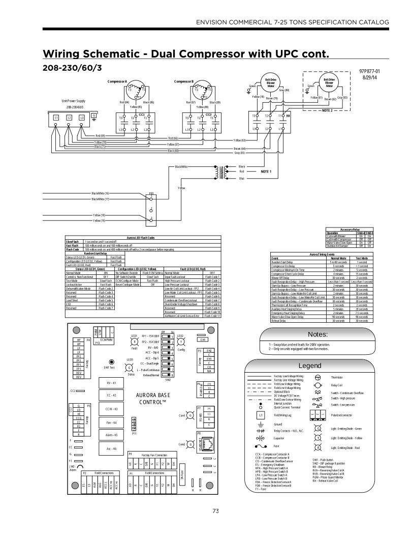
73
ENVISION COMMERCIAL 7-25 TONS SPECIFICATION CATALOG
Wiring Schematic - Dual Compressor with UPC cont.g p208-230/60/3
Compressor A
CC1T1
L1
T2
L2
T3
L3
T1T3
T2
Compressor B
CC2T1
L1
T2
L2
T3
L3
T1T3
T2
Green
Yellow (78) Brown (79)
Gray (80)Green
Belt DriveBlowerMotor
Gray (83)Brown (82)Yellow (81)
RBT2 T1T3
L2 L1L3
Red (69)Red (66) Yellow (63)
Brown (64)
NOTE 2
Yellow (70)Black (71) Yellow (67)
Black (68) Gray (65)
Unit Power Supply
208-230/60/3
L3L1 L2G
Red (84)Yellow (85)
Black (86) Red (87)Yellow (88)
Black (89)
Belt DriveBlowerMotor
PB1
2
1
3
Transformer
Black
Blue
Red
Yellow
Black/White
Accessory Relay
Cycle with BlowerCycle with CompressorWater Valve Slow OpenOutdoor Air Damper
SW2-4 SW2-5On OnOff OffOn OffOff On
Operation
Event Normal Mode Test ModeRandom Start DelayCompressor On DelayCompressor Minimum On TimeCompressor Short Cycle DelayBlower Off DelayFaul t Recogn ition Delay – High PressureStart-Up Bypass – Low PressureFaul t Recogn ition Delay – Low PressureStart-Up Bypass – Low Water/Air Coil LimitFaul t Recogn ition Delay – Low Water/Air Coil LimitFaul t Recogn ition Delay – Condensate OverflowThermostat Call Recognition TimeAuxi liary Heat Staging DelayEmergency Heat Staging Delay
Less than 1 second
5 to 80 seconds 1 second5 seconds < 1 second
30 seconds 2 secondsLess than 1 second
2 minutes 5 seconds4 minutes 15 seconds
2 minutes
2 minutes
30 seconds30 seconds 30 seconds
30 seconds30 seconds
30 seconds30 seconds30 seconds
2 seconds 2 seconds5 minutes2 minutes
20 seconds7.5 seconds
Aurora Timing Events
Reheat Delay 30 seconds 30 secondsWater Valve Slow Open Delay 90 seconds 90 seconds
Slow FlashFast FlashFlash Code
Status LED (LED1, Green)Configuration LED (LED2, Yellow)Faul t LED (LED3, Red)
Sta tus LED (LED1, Green)Normal ModeControl is Non-FunctionalTest ModeLockout ActiveDehumidification ModeReservedReservedLoad ShedESD
1 second on and 1 second off
Random Start DelayFast Flash
OFFON
Slow FlashFast Flash
Flash Code 2Flash Code 3
Flash Code 6
Flash Code 4Flash Code 5
Aurora LED Flash Codes
100 milliseconds on and 100 milliseconds off100 milliseconds on and 400 milliseconds off with a 2 second pause before repeating
Reserved Flash Code 7
Configuration LED (LED2, Yellow) Fault LED (LED3, Red)
Fast FlashFast Flash
No Software Overide Flash ECM Settin gDIP Switch Overide Slow Flash
Normal ModeInput Fault LockoutHigh Pressure LockoutLow Pressure Lockout
Low Water Coil Limi t Lockout - FP1Low Air Coil Limi t Lockout - FP2
ReservedCondensate Overflow LockoutOver/Under Voltage ShutdownReservedReservedAir/Water Coil Limit Sensor Error
Flash Code 1OFF
Flash Code 2Flash Code 3Flash Code 4Flash Code 5
Flash Code 8
Flash Code 6Flash Code 7
Flash Code 9Flash Code 10Flash Code 11
ECM Configu re Mode Fast FlashReset Configure Mode Off
CC2
EH1
Fact
ory
Faul t
ALG
ALMLSES ACC
c
Status
AURORA BASE CONTROL™
RV – K1
CC2
CC – K2
CC Hi – K3
Fan – K4
Alarm – K5
Acc – K6
ACC
no
ACC
nc
O/BCRLO G Y1 Y2 W DH
3A-Fu
se
O/BCRLO G Y1 Y2 W DH
LOG
HICCGCCFGFR
HPHPLP
FP2FP2FP1
REVREV
CFM
PWM
ECM PWM
Fact
ory
Factory Fan Connection
R R
CC
C
RS 48
5
EH2C
EH1C
CO
(+)(-)RCRS
485 E
xpFa
ctory
Com1
Com2
Config
G
G
G
YR
SW1 Test
FP1 – 15oF/30oF
JW2 - Alarm
P11
P5
P2 P1
P8
P7
P9
P6
P3
SW2
P13P4 FP2 – 15oF/30oF
RV – B/OACC – Dip 4
ACC – Dip 5CC – Dual/Single
L – Pulse/ContinuousReheat/Normal
Fact
ory U
se
Fi eld ConnectionsField Connections
C
LP
FP1
F
CC
G
Y1
1
2
3
4
5
6
7
8
Off On
N/A
RS48
5 NET
LED3
LED2LED1
Thermistor
Relay Coi l
Switch - Condensate OverflowSwitch - High pressure
Switch - Low pressure
Polarized connector
Factory Low Voltage WiringFactory Line Vol tage WiringField Low Voltage WiringField Line Voltage Wi ringOptional BlockDC Voltage PCB Traces
Internal JunctionQuick Connect Terminal
Field Wiring Lug
Ground
Relay Con tacts – N.O., N.C.
Field Zone Sensor Wi ring
Legend
L1
Capacitor
T
123
CCA – Compressor Contactor ACCB – Compressor Contactor BCO – Condensate Overflow SensorES – Emergency ShutdownHPA – High Pressure Switch AHPB – High Pressure Switch BLPA – Low Pressure Switch ALPB – Low Pressure Switch BFDA – Freeze De tection Sensor AFDB – Freeze De tection Sensor BF1 – Fuse
Fuse
Light Emitti ng Diode - GreenG
Light Emitti ng Diode - YellowY
Light Emitting Diode - RedR
SW1 – Push buttonSW2 – DIP package 8 positionRB – Blower RelayRVA – Reversing Valve Coi l ARVB – Reversing Valve Coi l BPGM – Phase Guard Moni torRH – Reheat Valve Coi l
1 – Swap blue and red leads for 208V operation.2 – Only on units equipped with two fan motors.
Notes:
NOTE 1
8/29/1497P877-01
Black/White (16)
Black/White (17)
Yellow (18)
Yellow (19)
74
ENVISION COMMERCIAL 7-25 TONS SPECIFICATION CATALOG
Engineering Guide Specifi cationsg g pGeneral
Furnish and install WaterFurnace Water Source Heat
Pumps, as indicated on the plans. Equipment shall be
completely assembled, piped and internally wired.
Capacities and characteristics as listed in the schedule
and the specifications that follow. The reverse cycle
heating/cooling units shall be either suspended type
with horizontal air inlet and discharge or floor mounted
type with horizontal air inlet and vertical upflow/side air
discharge. Units shall be AHRI/ISO 13256-1 certified (080-
120) and listed by a nationally recognized safety-testing
laboratory or agency, such as ETL Testing Laboratory.
Each unit shall be computer run-tested at the factory with
conditioned water and operation verified to catalog data.
The units shall be designed to operate with entering liquid
temperature between 20°F and 120°F [-6.7°C and 48.9°C].
Refer to the performance data tables actual operating
range.
Casing and Cabinet
The cabinet shall be fabricated from heavy-gauge
galvanized steel and finished with corrosion-resistant
powder coating (vertical units). This corrosion protection
system shall meet the stringent 1000 hour salt spray test
per ASTM B117. The interior shall be insulated with 1/2-
inch thick, multi-density, Cleanable aluminum foil coated
glass fiber with edges sealed or tucked under flanges to
prevent the introduction of glass fibers into the discharge
air. Standard cabinet panel insulation must meet NFPA
90A requirements, air erosion and mold growth limits of
UL-181, stringent fungal resistance test per ASTM-C1071
and ASTM G21, and shall meet zero level bacteria growth
per ASTM G22. Unit insulation must meet these stringent
requirements or unit(s) will not be accepted.
Blower and compressor compartment access panels shall
be ‘lift-out’ removable with supply and return ductwork in
place.
A duct collar shall be provided on the supply air opening.
Standard size 2 in. [5.1 cm] disposable filters shall be
provided with each unit. The upflow vertical units shall
have a removable insulated divider panel between the air
handling section and the compressor section to minimize
the transmission of compressor noise and to permit
operational service testing without air bypass. Vertical
units shall be supplied with left or right horizontal air
inlet and top or side air discharge. Horizontal units shall
be supplied with left or right air inlet and end or side air
discharge.
Option: A 2 in. [5.1 cm] wide MERV 13 filter shall be installed In filter rack for high efficiency filter applications.
The compressor shall be double isolation mounted (160-
300) using selected durometer grommets to provide
vibration free compressor mounting. The compressor
mounting bracket shall be acoustically deadened
galvanized steel to prevent vibration transmission to the
cabinet.
Option: A Super Quiet Sound package shall include multi-density full coverage compressor blanket.
The drain pan shall be of plastic (080-120) or stainless
steel (080-300) construction to inhibit corrosion inhibit
bacterial growth. Drain outlet shall be located on pan as to
allow complete and unobstructed drainage of condensate.
The unit as standard will be supplied with solid-state
electronic condensate overflow protection. Mechanical
float switches WILL NOT be accepted. Vertical units
shall be furnished with a copper FPT condensate drain
connection and an internal factory installed condensate
trap. Horizontal units shall have a pipe drain connection
suitable for standard 3/4 in. PVC glue fittings.
Refrigerant Circuit
All units shall utilize the non-ozone depleting and low
global warming potential refrigerant R-410A. All units shall
contain a sealed refrigerant circuit including a hermetic
motor-compressor, bidirectional thermostatic expansion
valve, finned tube air-to-refrigerant heat exchanger,
reversing valve, coaxial tube water-to-refrigerant heat
exchanger, optional hot water generator coil, and service
ports.
Compressors shall be high-efficiency single scroll type
designed for heat pump duty and mounted on vibration
isolators.
The air coil shall be sized for low-face velocity and
constructed of lanced aluminum fins bonded to rifled
aluminum tubes in a staggered pattern not less than three
rows deep for enhanced performance. AlumiSeal™ electro-
coated air coil for maximum protection against formicary
corrosion.
The coaxial water-to-refrigerant heat exchanger shall be
designed for low water pressure drop and constructed of
a convoluted copper inner tube and a steel outer tube.
Refrigerant to air heat exchangers shall utilize enhanced
corrugated lanced aluminum fins and rifled copper tube
construction rated to withstand 600 PSIG (4135 kPa)
refrigerant working pressure. Refrigerant to water heat
exchangers shall be of copper inner water tube and steel
refrigerant outer tube design, rated to withstand 600
PSIG (4135 kPa) working refrigerant pressure and 450
PSIG (3101 kPa) working water pressure. The thermostatic
expansion valve shall provide proper superheat over the

75
ENVISION COMMERCIAL 7-25 TONS SPECIFICATION CATALOG
entire liquid temperature range with minimal “hunting.”
The valve shall operate bi-directionally without the use of
check valves.
Option: Cupronickel refrigerant to water heat exchangers shall be of copper-nickel inner water tube and steel refrigerant outer tube design, rated to withstand 600 PSIG (4135 kPa) working refrigerant pressure and 450 PSIG (3101 kPa) working water pressure. Water lines shall also be of cupronickel construction.
Option: Insulated water-to-refrigerant heat exchanger and refrigerant suction lines shall be insulated to prevent condensation at low liquid temperatures.
Option: Insulated water-to-refrigerant heat exchanger,water lines and refrigerant suction lines shall be insulated to prevent condensation at low liquid temperatures below 50 °F.
Blower and Motor Assembly
All units shall have belt-driven centrifugal blowers. Blower
motors shall be permanently lubricated with thermal
overload protection. Units supplied without permanently
lubricated motors must provide external oilers for easy
service. The blower shall be double-width double inlet
forward curved with dynamically balanced wheels. Blower
motors shall be 1725 rpm, 56 frame sealed ball bearing
type. The drive shall include fixed pitch blower sheave and
variable pitch motor sheave sized for 115% of the blower
brake horsepower. The blower and motor assembly must
be capable of overcoming the external static pressures as
shown on the schedule. Airflow / Static pressure rating
of the unit shall be based on a wet coil and a clean filter
in place. Ratings based on a dry coil and/or no filter, or
on an ESP less than 0.25 in. (6.35 mm w.g.) shall NOT be
acceptable.
Option: Various blower drive packages for selectable static pressure/airflow.
Option: High static blower motors available on select models.
Electrical
A control box shall be located within the unit compressor
compartment and shall contain a 75VA transformer, 24
Volt activated, 2 pole compressor contactor, terminal
block for thermostat wiring and solid-state controller for
complete unit operation. Electro-mechanical operation
WILL NOT be accepted. Units shall be name-plated for
use with time delay fuses or HACR circuit breakers. Unit
controls shall be 24 Volt and provide heating or cooling as
required by the remote thermostat/sensor.
An Aurora microprocessor-based controller that interfaces
with a multi-stage electronic thermostat to monitor and
control unit operation shall be provided. The control shall
provide operational sequencing, blower speed control,
high and low pressure switch monitoring, freeze detection,
condensate overflow sensing, lockout mode control, LED
status and fault indicators, fault memory, field selectable
options and accessory output. The control shall provide
fault retry three times before locking out to limit nuisance
trips.
A detachable terminal block with screw terminals will
be provided for field control wiring. All units shall have
knockouts for entrance of low and line voltage wiring. The
blower motor and control box shall be harness plug wired
for easy removal.
Option: An Aurora Unitary Protocol Converter (UPC) shall be included that communicates directly with the AuroradHeat Pump Controls and allows access/control of a variety
of internal Aurora heat pump operations such as sensors,
relay operation, faults and other information. In turn, the
UPC shall convert the internal Aurora Modbus protocol to
BACnet MS/TP, or N2 protocols for communication over a
BAS system. Additional individual unit configuration items
such as ECM fan speeds or freeze protection settings shall
be directly available over the BAS without the need for
access to the actual heat pump.
Option: Aurora UPC DDC communication protocols: LonWorks
Piping
Supply and return water connections shall be copper
fittings which eliminate the need for backup wrenches
when making field connections. Optionally, all water
piping shall be insulated to prevent condensation at low
liquid temperatures.
Engineering Guide Specifi cations cont.g g p

Revision Guide:
Pages: Description: Date: By:
4, 12-24 Added Waterside Economizer option into Nomenclature, removed FX10 Control
Option, Added ABC and UPC Controls
18 May 2015 MA
70 Revision table added 10 Nov 2014 MA
4,30 Updated Nomenclature and Physical Data table 10 Nov 2014 MA

Product: Envision Series
Type: Geothermal/Water Source Heat Pump
Size: Commercial 7-25 Tons
Document: Specification Catalog
Manufactured by
WaterFurnace International, Inc.
9000 Conservation Way
Fort Wayne, IN 46809
www.waterfurnace.com
©2015 WaterFurnace International, Inc., 9000 Conservation Way, Fort Wayne, IN 46809-9794. WaterFurnace has a policy of continual product research and development
and reserves the right to change design and specifi cations without notice.
SC1021ANB 05/15
*SC1021ANB*