24V Specifi - WaterFurnace
34
Design Features Description of Operation Damper Specifications System Application and Design SC1678EW 05/17 IntelliZone2 ● 24V Specification Catalog and Design Four Zone Capability Comfort Zoning System
Transcript of 24V Specifi - WaterFurnace

Design Features
Description of Operation
Damper Specifi cations
System Application and Design
SC1678EW 05/17
Inte
lliZ
on
e2 ●
24
V S
pecifi c
ati
on
Cata
log
an
d D
esi
gn
Four Zone Capability
Comfort Zoning System


INTELLIZONE2 ● 24V SPECIFICATION CATALOG
Table of Contents
Introduction . . . . . . . . . . . . . . . . . . . . . . . . . . . . . . . . . . . . . . . . . . . . . . . . . . . . . . . . . . . . . . . . . . . . . . 5
IntelliZone2 Features. . . . . . . . . . . . . . . . . . . . . . . . . . . . . . . . . . . . . . . . . . . . . . . . . . . . . . . . . . . . . . . 6
Design Features . . . . . . . . . . . . . . . . . . . . . . . . . . . . . . . . . . . . . . . . . . . . . . . . . . . . . . . . . . . . . . . . . . . 7
IntelliZone2 ● 24V Components . . . . . . . . . . . . . . . . . . . . . . . . . . . . . . . . . . . . . . . . . . . . . . . . . . . . . 8
IntelliZone2 ● 24V Configuration . . . . . . . . . . . . . . . . . . . . . . . . . . . . . . . . . . . . . . . . . . . . . . . . . . . . 9
Description of Operation - Package Unit . . . . . . . . . . . . . . . . . . . . . . . . . . . . . . . . . . . . . . . . . . . . 14
Wiring Schematic. . . . . . . . . . . . . . . . . . . . . . . . . . . . . . . . . . . . . . . . . . . . . . . . . . . . . . . . . . . . . . . . . 16
Damper Specifications . . . . . . . . . . . . . . . . . . . . . . . . . . . . . . . . . . . . . . . . . . . . . . . . . . . . . . . . . . . . .18
Zone Selection . . . . . . . . . . . . . . . . . . . . . . . . . . . . . . . . . . . . . . . . . . . . . . . . . . . . . . . . . . . . . . . . . . . 19
IntelliZone 2 Design Software . . . . . . . . . . . . . . . . . . . . . . . . . . . . . . . . . . . . . . . . . . . . . . . . . . . . . . 20
Special Zoning Applications . . . . . . . . . . . . . . . . . . . . . . . . . . . . . . . . . . . . . . . . . . . . . . . . . . . . . . . .21
Peak Heating and Cooling Demands . . . . . . . . . . . . . . . . . . . . . . . . . . . . . . . . . . . . . . . . . . . . . . . . 22
System Sizing . . . . . . . . . . . . . . . . . . . . . . . . . . . . . . . . . . . . . . . . . . . . . . . . . . . . . . . . . . . . . . . . . . . . 23
IntelliZone2 ● 24V with SAH Air Handler . . . . . . . . . . . . . . . . . . . . . . . . . . . . . . . . . . . . . . . . . . . . 25
Description of Operation - Split System . . . . . . . . . . . . . . . . . . . . . . . . . . . . . . . . . . . . . . . . . . . . . 26
SAH 5 Speed ECM (SAH Option A) . . . . . . . . . . . . . . . . . . . . . . . . . . . . . . . . . . . . . . . . . . . . . . . . . 28
Wiring Schematic. . . . . . . . . . . . . . . . . . . . . . . . . . . . . . . . . . . . . . . . . . . . . . . . . . . . . . . . . . . . . . . . . 29
Revision Guide . . . . . . . . . . . . . . . . . . . . . . . . . . . . . . . . . . . . . . . . . . . . . . . . . . . . . . . . . . . . . . . . . . . 33

4
INTELLIZONE2 ● 24V SPECIFICATION CATALOG
The IntelliZone2 ● 24V Comfort Zoning System is a
residential and/or commercial zone control system
which works with traditional 24V non-communicating
geothermal heat pumps to condition up to 4 zones.
Each zone is controlled by its own space thermostat and
damper motor(s) using a maximum 1-inch W.G. inlet static
pressure at zone dampers. The IntelliZone2 ● 24V monitors
the thermostats, puts the system in the proper mode of
operation, and energizes the correct number of stages of
heating or cooling.
The IntelliZone2 ● 24V was designed to solve problems
that are inherent with the concept of HVAC zoning by:
• Using “Multiple Level” zone calls (Heating 0-3,
Cooling 0-2), allowing the controller to better
estimate the demand of each zone and thus
condition space most efficiently
• Designed a high value control which is both
easy to install and service
The IntelliZone2 ● 24V System is a perfect match for basic geothermal systems, extending comfort and energy savings.
By choosing or specifying IntelliZone2 ● 24V Series products, you can be assured that your customer is investing in an
exceptional comfort system and peace of mind for many years to come.

5
INTELLIZONE2 ● 24V SPECIFICATION CATALOG
IntroductionThe IntelliZone2•24V Comfort Zoning system is to be used
with heat pumps/air handlers equipped with Aurora Base
Controls (ABC) or Premier Controls. If the heat pump/air
handler has Aurora AXB or AHB controls you must use the
IntelliZone2 Comfort Zoning system.
Zoning is a method of ensuring that all areas of a home or
building receive the right amount of heating or cooling.
Zoning allows the occupant to independently control the
temperature in each area of the building. If desired, all
areas can be adjusted for occupancy patterns and uses.
ThermostatIntelliZone2 • 24V
Zone Damper Supply Register
Geothermal UnitIntellizone2 • 24V
IntelliZone2 Control
BasementZone
Main Living Area Zone
Master Suite Zone
Bedrooms Zone
The above illustration is representational and is not intended as a guide for IntelliZone2 ● 24V system installation.
Zoning is particularly useful where normal heat distribution
patterns result in uneven temperature control. For example,
a building that is partly below grade can use zoning
to eliminate uneven temperature control between the
basement and the rest of the building. Large buildings that
might have long, unequal length duct runs can use zoning
to equalize the delivery of conditioned air. Buildings with
many large windows can use zoning to compensate for
solar heat gain and radiation losses at night.
Along with providing comfort, zoning can provide energy
savings by keeping various zones at desired set points
without over-cooling or overheating. In effect, zoning
mandates that the heating/cooling system condition only
the portions (or zones) of the building which need to be
conditioned. This translates into shorter compressor run
times and ultimately lower space conditioning bills.

6
INTELLIZONE2 ● 24V SPECIFICATION CATALOG
IntelliZone2 ● 24V Features
IntelliZone2 ● 24V Features• Up to 4 zones possible in dual capacity units and 2 zones
for single speed units• 4.3 in. Color touchscreen MasterStat for ease of use• TPCC32U01, SensorStat-Remote-Kit, ZoneStat, or
SensorStat options for zones 2-4• Communicating thermostat features:
- Full zone setback programming from each zone.- Dealer configuration mode- Full color touchscreen display
• Full text Faults/Alarms from IntelliZone2 ● 24V System• Adjust zone setpoints from MasterStat, TPCC32U01 or
ZoneStat• 2 (spring) or 3 wire damper options.• Central Zone option operates all dampers open
on temperature measurement from MasterStat for construction or service operation.
• Economy/comfort settings for each zone to reduce operating costs In less important rooms.
• Zones are 'sized' to provide more proper compressor and blower staging.
• Staging flexibility allows several up/down staging options for customization to your application.
Flexibility in Zone Comfort ControlThe IntelliZone2 ● 24V allows comfort or economy mode selections for each zone.
In ‘Comfort Mode’ a single zone call for conditioning will engage the compressor and allow a minimal set point variation, thus providing ultimate comfort. However in ‘Economy Mode’ a single zone call for conditioning will be ignored until either a next level call for that zone or a second zone call occurs. This will allow slightly greater temperature fluctuations in these zones allowing lower operating costs in areas such as rec rooms, unused bedrooms where slightly higher temperature variation would not be noticeable.
Flexibility in System Staging(single or dual capacity equipment)The IntelliZone2 ● 24V System allows four different staging options. Once the compressor call has been initiated by a zone, the compressor will be upstaged using one of four staging options in single or dual capacity equipment. Separate staging options are available for heating and cooling. The modes are Normal, Quicker, Faster1 and Faster2. More detail is listed later in this document.
Eliminating Bypass DamperBy utilizing the full functionality of the ECM blower motor, the bypass damper can be eliminated from the zone system. In effect, the ECM replaces the bypass damper.
In conventional systems, the air handling device can deliver airflow only at one or two levels, which means a significant amount of excess air must be “bypassed” to the return. By looking at which zones are calling, the IntelliZone2 ● 24V determines the most efficient compressor speeds. The heat pump will control the blower speeds and as long as there are 3-4 blower speeds online for G (continuous fan), Y1, Y2, and W the system has the ability to deliver the correct amount of airflow that the structure is calling for, there is no need for bypass.
By varying the airflow level per the needed output capacity of the heat pump, bypass is eliminated and the correct amount of air is delivered to the house. Consult the heat pump technical literature for more information on airflow setup.
Efficient Space ConditioningTraditional zone control systems control single-speed compressors and single-speed blowers and typically use single heating and cooling calls to determine space conditioning needs. By operating at only one capacity level, these traditional systems are seriously handicapped in their ability to handle the varying load of the structure.
The IntelliZone2 ● 24V control system controls the single and dual-capacity equipment with multiple level zone calls allows the IntelliZone2 ● 24V to better match the demands of the space.
One of the goals of the IntelliZone2 ● 24V system is to minimize operation by operating at the lowest, most efficient speed possible. The IntelliZone2 ● 24V makes logic decisions which minimize compressor run-times and help decrease energy cost. For example: If one or more zones have Y1 demand calls, the thermostat has determined that the particular zones need conditioning, but the demand is at a low level. The IntelliZone2 ● 24V control algorithm will take these low level calls and determine what compressor capacity will satisfy the zone calls. Thus, the system operates in lower capacity most of the time and intelligently provides cost-efficient space conditioning control.
Many times, as in any structure, the space conditioning peak load for each zone can happen at a different time throughout the day. This may be due to sun, wind, or even the zone use. This diversity can sometimes allow slightly smaller capacity equipment to condition one zone during its morning peak and then condition another during its afternoon peak, whereas an unzoned structure would have to be sized with larger capacity equipment to condition both areas at once.

7
INTELLIZONE2 ● 24V SPECIFICATION CATALOG
Design Features
Full Color Touchscreen Display and Diagnostic LEDs With traditional zone control systems, the installer typically
has a difficult time determining the status of the inputs
and outputs of the zone control board. The IntelliZone2
Panel employs an LED for each output and the color
display shows all inputs and outputs. With just a glance,
the installer is able to quickly determine what inputs the
IntelliZone2 is receiving and what outputs the IntelliZone2
is sending to the unit via the IntelliZone2 ● 24V relay board.
Application Flexibility• Multiple level zone calls communicate exact zone load
requirements for intelligent equipment control.
• Controls up to four zones with dual capacity compressor
and two zones with single-speed compressor
• Zone size as small as 25% of whole house with
dual capacity compressor and 50% single speed
• Individual zone-selectable economy or comfort modes.
• Four staging options (normal, quicker, Faster1 and
Faster2) to allow a wide range of comfort and energy
consumption solutions.
• Separate staging options available for heating and
cooling
• Simple, reliable thermostat operation; simple
programming for the homeowner.
• Individual zone-selectable continuous or
intermittent blower.
• Smart algorithm serves simultaneous heating and
cooling demands.
• Reduces blower power consumption.
IntelliZone2's Sophisicated Microprocessor Controlwith LEDs to Display Inputs and Outputs
• Installation and Service Advantages
• Bypass damper not needed (minimal oversizing of
ductwork may be desired).
• All low voltage wiring (24VAC).
• Central mode control for temporary conditioning of the
whole house using one thermostat.
• Low cost communicating zone thermostats.
• Three-wire or two-wire damper actuators for maximum
performance and reliability.
• Transformer with integrally mounted circuit breaker.
• LED indicators (damper operation, mode, fault) and
troubleshooting screens displayed on MasterStat for
easy diagnostics.

8
INTELLIZONE2 ● 24V SPECIFICATION CATALOG
IntelliZone2 ● 24V Components
IntelliZone2 ● 24V Conversion BoardThe IntelliZone2 ● 24V conversion board communicates via Modbus with
the IntelliZone2 relay board and converts the Modbus communication into
typical 24VAC signals to be sent to the ABC or Premier heat pump control.
This zoning system is designed for use with non-communicating heat pump
controls.
IntelliZone2 Relay Board (Firmware Version 2.01 or Later)
The IntelliZone2 relay board provides basic relay logic for the damper
operation and serves as a common connection point for all IntelliZone2
thermostats and the heat pump.
IntelliZone2 MasterStatThe IntelliZone2 MasterStat is the master control for the system and has all
of the programming for operation. It is a 4.3 in. communicating color touch
screen device that also functions as a zone thermostat for Zone 1. Optional
remote sensor capability is also available.
IntelliZone2 ZoneStat
The IntelliZone2 ZoneStat is a zone thermostat option for any of Zones 2
through 4. It has full setback capability and communicates to the
IntelliZone2 system.
IntelliZone2 SensorStat
The IntelliZone2 SensorStat is a zone thermostat option for any of Zones 2
through 4. It has full setback capability (through the MasterStat interface
only) and communicates to the IntelliZone2 system.
IntelliZone2 Outdoor Sensor
The IntelliZone2 Outdoor Sensor measures the outdoor temperature and
communicates to the IntelliZone2 system. This temperature is displayed on
the MasterStat, and also used to balance response as well as auxiliary electric
heat use. The Outdoor Sensor is included in every kit.
TPCC32U01 (Optional) (Firmware Version 3.01 or Later)
The TPCC32U01 is a 4.3 in. communicating color touch screen device that
can be used as a zone thermostat for zones 2 through 6. It has full set back
capability and communicates to the IntelliZone2 System.
SensorStat-Remote-Kit (Optional)
The SensorStat-Remote-Kit is an option for an invisible thermostat installation
and communicates with the IntelliZone2 relay panel. The kit will include
the SensorStat-Remote, TSU03 (mud in sensor) and wire nuts. This kit will
monitor the zone temperature in zones 2 through 6. All set point adjustments
are made at the MasterStat.

9
INTELLIZONE2 ● 24V SPECIFICATION CATALOG
IntelliZone2 ● 24V Confi guration
Communication Basics and CommunicationAlthough some components of this zoning system
communicate with each other the IntelliZone2 ● 24V is
designed for non-communicating heat pump controls.
Communication between the thermostats, IntelliZone2
relay board and IntelliZone2 ● 24V board is a 4-Wire
Modbus protocol. The IntelliZone2 ● 24V board converts
the Modbus communication into 24VAC signals which
are delivered to the heat pump control. These 24VAC
signals will turn on compressor, blower, reversing valve and
auxiliary heat.
The 4-wire Modbus communication lines are comprised
of an R (+24VAC), C (common), a ‘+’ and ‘-‘. The terminals
marked with a ‘+’ and ‘-‘ should not be switched, although
damage may not occur to the boards, communication is
not possible. The communication voltage and current
are small therefore 24 awg wire is adequate for these
communication lines.
Software VersionsSoftware versions of the IntelliZone2 MasterStat can be found in the startup screen or in the AID Tool Aurora Config screen. The software version on the TPCC32U01 can be found on the settings screen. Firmware can be uploaded to the MasterStat or TPCC32U01 via the USB port on the thermostat. Consult your local representative or tech service for details.
NOTE: When updating the firmware on the TPCC32U01 each thermostat will need to be updated. Firmware for the MasterStat and TPCC32U01 are NOT the same. After the TPCC32U01 firmware is updated to v3.01, or later, go into the installers screen and select restore defaults. If you do not restore the default setting the zone will not be displayed on the TPCC32U01.
Wiring and Configuring the Thermostats/SensorsThe Zone Sensors should be wired with the MasterStat on Zone 1 using standard 4-wire thermostat cable (if issues with EMI, shielded cable should be used and grounded at the ‘–‘ terminal on one end). The other zones should be added sequentially on the relay board until complete. The dip switch on the back of each ZoneStat or SensorStat should be selected for the appropriate zone number; for instance, Zone 2 stat should be selected using the DIP switch on the back for ‘off, off, off’.
The TPCC32U01 will auto detect that it is attached to the IntelliZone2 relay panel and will display the screen below.
Use the up/down arrows ▲▼ to select the zone.If more than one zone is assigned the same zone number an error will be displayed on the TPCC32U01 and Master-Stat. After the initial confi guration, to change the zone numbers enter the confi guration mode by holding a fi nger over the Zone number in the upper left hand corner of the Main screen for 5 sec. Select zone number and use the up/down arrow▲▼ to adjust.
ZoneStats/SensorStats PCB
A+RCB- P
14 –
Zon
e 4
A+RCB- P
15 –
Zon
e 5
A+RCB-Zo
ne 4
Sta
t
On32 1
Zone 4 code shown
A+RCB-Zo
ne 5
Sta
tOn32 1
Zone 5 code shown
ZoneStat
SensorStat
Zone ID must be set for each Zone 2-6. ID can beconfirmed on ZoneStat by pressing cancel button for
5 sec. ID shown on display. See Zone ID Codes.
Zone ID must be set for each Zone 2-6. ID cannot beconfirmed on Zone SensorStat. See Zone ID Codes.
Relay Board
A+
R
C
B- P16
– Z
one
6DX+
R
C
DX-
S1
S2
Opt
iona
lR
emot
eS
enso
r
IntelliZone2Relay Board
TPCC32U01
On
32 1
On
32 1
On
32 1
Zone 4 Zone 5Zone 3On
32 1
Zone 2On
32 1
Zone 6Zone ID Codes
NOTES:1) Zone ID must be set for each Zone 2-6. ID can be confirmed on ZoneStat by pressing cancel button for 5 sec. ID shown on display.2) Small screw driver can be used to set ID thru protective plastic skin!3) MasterStat always Zone 1. Zone ID not necessary. 4) TPCC32U01 zone is set through its touchscreen.
Zones 5 & 6 are not applicable with the IntelliZone2•24V System
(Note 4)
10
INTELLIZONE2 ● 24V SPECIFICATION CATALOG
The setup and configuration mode should be entered at the MasterStat by holding a finger over the IntelliZone2 ● 24V logo for 5 sec. The Configuration and Setup mode will appear automatically.
NOTE: These options are intended to be used by the installer. End users are not advised to change or modify any of these settings. Doing so may make your equipment stop workingproperly and/or may void the warranty of the zoning system
as well as the equipment connected to the thermostat.
It should be noted that the MasterStat Z2TK troubleshooting harness can be useful during setup by allowing the temporary connection of the MasterStat directly at the IntelliZone2 relay
board for ease of configuration or servicing.
Equipment and Number of ZonesThe first screen is Equipment and # of Zones. Here the total number of desired zones and the type of equipment is selected. Select either Single Speed or Dual Capacity. Press the up and down arrows until the desired number of zones appears. The zones should always be installed sequentially starting with the MasterStat always in Zone 1.
• Single speed equipment is limited to a maximum of
2 zones
• Dual Capacity equipment is limited to a maximum of
4 zones
NOTE: If the number of zones selected is less than 4, the
remaining zones will be disabled.
DamperThe Damper screen allows the selection of either 2 wire
(spring closed) or 3 wire (power open/power closed) type.
StagingStaging allows custom selection of staging for cooling and
heating, independently.
The IntelliZone2 ● 24V system allows separate staging
options for cooling and heating. There are four options
for each mode which are explained below. As an example,
staging for cooling can be set for ‘Normal’ while staging for
heating is set for ‘Faster2’. Allowing heating and cooling
staging to be independent of each other will provide better
comfort all year long. Once the compressor call has been
initiated by a zone, the compressor will be upstaged using
one of the four staging options.
CB-
A+R
Use the Z2TK Harness kit to temporarily connect the IntelliZone2 MasterStatdirectly to the IntelliZone2 Relay Panel for ease of setup or troubleshooting.
IntelliZone2Relay Panel
Z2TK
Kit
P3 -
Maste
rStat
Loca
l
IntelliZone2 ● 24V Confi guration cont.

11
INTELLIZONE2 ● 24V SPECIFICATION CATALOG
Single and Dual Staging
Normal - This “as shipped” mode will upstage the blower
and compressor normally.
Quicker - This mode will upstage the blower, compressor
and auxiliary electric heat more expediently than “normal”
mode for increased comfort.
Faster1 - This mode allows for a timed element in compressor (heating and cooling) and electric heat (heating) upstaging in 45% and 70% zones for situations in which ‘Quicker’ upstaging is inadequate. If the heat pump is already operating in first stage and a 45% or 70% zone has had a demand for 30 continuous minutes then second stage will be activated. If after another continuous 30 minutes the H3 demand is still present from a 45% or 70% zone, third stage will be activated until the zone call is reduced to a H2. Airflow will increase with compressor staging/EH during this period. If the heat pump is already operating in second stage and a 45% or 70% zone has had a demand for 30 continuous minutes then third stage will be activated until the demand is reduced to H2. Airflow will be increased to EH selection during this period.
Faster2 - This mode allows for a timed element in compressor (heating and cooling) and electric heat (heating) upstaging in 45% and 70% zones for situations in which ‘Quicker’ upstaging is inadequate. If the heat pump is already operating in first stage and a 45% or 70% zone has had a demand for 15 continuous minutes then second stage will be activated. If after another continuous 15 minutes the H3 demand is still present from a 45% or 70% zone, third stage will be activated until the zone call is reduced to a H2. Airflow will increase with compressor staging/EH during this period. If the heat pump is already operating in second stage and a 45% or 70% zone has had a demand for 15 continuous minutes then third stage will be activated until the demand is reduced to H2. Airflow will be increased to EH selection during this period.
Zone ConfigurationZone configuration allows the selection of the zone size and the zone priority. The zone can be selected by touching the upper right screen text noting the zone. In this way you can cycle thru all of the active zones to view the configuration.
Zone PercentageSelecting the zone percentage can also be calculated by using the IntelliZone2 Design software. This percentage represents an approximation of the maximum heating or cooling load percentage of the zone and thus to a certain extent volume of airflow. The IntelliZone2 ● 24V allows 0, 25, 45, and 70% selections. Some general rules to follow in this selection procedure are as follows:• Pick the larger percentage for major living areas such
as family rooms, etc.• Pick the smaller percentage for minor living areas such
as dens or bedrooms.• Pick a larger percentage if more branches are required
than the load indicates due to large area per load (i.e. unfinished insulated basement).
• The IntelliZone2 Design software should be used to aid in the selection and calculation of design cfm.
• The IntelliZone2 determines modes as a proportion of the total demand. A simple example of this to begin with is a two-zone system in the cooling mode. If each zone is set at 70% we have the following scenario:
Zone 1 = 50% Zone 2 = 50%
NOTE: All Zone % calculations are ‘normalized using the following process: We now must determine what percentage of the total load each zone represents. To perform this operation, add the two zones together 70 + 70 = 140. One zone would then be 70/140 or 50%.
The IntelliZone2 ● 24V then reduces the total demand based upon thermostat demand. A “Y1” call in the above example will result in one half of the zone demand in this case 1/2 of 50% for a 25% system demand. A common complaint is insufficient cooling when only one zone is calling for cooling. The IntelliZone2 will not initiate a “Y2” output to the unit until it senses a 51% total system demand (This is when the IntelliZone2 is set for normal upstaging). If the IntelliZone2 is set for quicker upstaging it drops the total system demand required to 41% to initiate a Y2 output.
By this example, it will require a “Y2” call from one zone (50%) and a “Y1” call from the second zone (25%). This will give us a total system demand of 50% + 25% = 75%. System demand for three-zone and four-zone systems are computed in the same manner.
Heating demand is determined in the same manner, but we now have a third stage instead of two for cooling. The IntelliZone2 assigns values as follows: Y1 = 40% Y2 = 80% Y3 = 100%
We know from the previous example that the IntelliZone2 ● 24V will initiate a “Y2” output to the compressor when it is set to normal upstaging and 51% of total demand is needed. It will issue a “W” call to the unit when there is a 90% total demand.
IntelliZone2 ● 24V Confi guration cont.

12
INTELLIZONE2 ● 24V SPECIFICATION CATALOG
It is a common assumption that if you have a house with two zones equally divided each zone should be set at an equal amount, usually 70%. As can be seen in the above example, it will take a “Y3” call from one zone as well as a “Y2” call from the second zone to obtain auxiliary heat.
This is a simple example, but three-zone and four-zone systems are calculated in the same manner. Blower speeds are not set or regulated by the zoning system. Blower speeds are set at the heat pump. As a serviceman, the temptation arises, in some instances, to influence the logic of the board by jumping “Y1” and “Y2”. While this will create a quicker response, the ductwork of that zone must be capable of handling the cfm delivered by the unit (i.e., if a “Y2” signal is given to the unit, can the ductwork handle the total cfm of the unit).
When setting up a new system remember that if you have unused zones they must be set to zero. If they are not, the setting that they have will be included in the total demand preventing the other zones from operating correctly, as there will be no inputs on those zones.
The IntelliZone2 ● 24V allows the selection of either comfort or economy mode in each individual zone to provide maximum savings in areas that allow it (such as workshops and basements), while maintaining perfect comfort in the zones where accurate temperature is most desired (such as bedrooms and baths).
Zone Priority
Comfort Mode - A single zone call (Y1) for conditioning will engage the compressor and allow a minimal set point variation, thus providing ultimate comfort.
Economy Mode - A single zone call (Y1) for conditioning will be ignored by the IntelliZone2 ● 24V until either a Y2 call is initiated from the same zone or another zone calls for conditioning (Y1). This allows a slightly greater set point variation than in comfort mode. This setting prevents less important zones from energizing the compressor
unless it is really needed, thus saving money. As a bonus in this mode, upon a Y1 call, the IntelliZone2 may try to precondition the zone with return air from other zones already satisfied and, in some cases, can preclude the need for energizing the compressor.
Zones - Displays the inputs that the Intellizone2 ● 24V is
receiving.
Status - Displays the outputs that the IntelliZone2 ● 24V is sending to the equipment.
Test Mode - In Test mode ‘Central Zone’ mode can be selected. In Central mode all dampers are opened and thermostat readings are taken ONLY from the Zone 1 MasterStat. This will approximate operation without a zone system (all dampers open and Masterstat controls temperature) and can be useful during initial construction of the home or during service etc.
Also in ‘Central Zone’ mode each damper can be individually cycled off/on to verify operation during Installation or service. It should be noted that the MasterStat Z2TK troubleshooting harness can be useful here by allowing the temporary connection of the MasterStat directly at the IntelliZone2 relay board for ease of configuration or servicing.
IntelliZone2 ● 24V Confi guration cont.

13
INTELLIZONE2 ● 24V SPECIFICATION CATALOG
IntelliZone2 ● 24V Confi guration cont.Thermostat Type
NORMAL/DUAL FUEL Normal - Used for normal operation Dual Fuel - Not Applicable - Operation is not available with IntelliZone2 ● 24V since it is a non communicating system
Fan with Heat Option - Not Applicable
Aux Heat Lockout - Allows the configuration to lockout electric heat above a selected outdoor temperature. The outdoor sensor (OAT) must be installed on the IntelliZone2 Relay Board. This setting is adjustable in 5°F increments from NONE to 40°F. This will provide full heat pump capacity without electric heat above the selected temperature. When the outdoor temperature drops below the selected temperature, then electric heat will be energized when the demand is present.
Differential- This adjustment will vary the number of degrees, from the set point, before a call for heating or cooling is made. Adjustments can range between 0.2° and 4° differential. Default is 0.5° differential. (If your set point is 70° in heating, your thermostat will not call for heat until the temperature is 69.5°, with a 0.5° differential setting).
OffsetsTemperature Offsets – This option allows calibration
(or deliberate miscalibration) of the room temperature sensor. The Offset function only works on the MasterStat. There are various reasons why the displayed temperature would be adjusted to a higher or lower value. NOTE: Do not adjust for 30 minutes after installation because board may be heated by handling. The selected number is the number of degrees, plus or minus, which will be added to actual temperature. The numbers can range between -5˚ and +5˚. Default values are set to 0˚ offset.
Temperature Offset Remote Indoor Offset (if sensor is attached) Outdoor Offset (if sensor is attached)
Humidity Offset – This option allows calibration of the humidity sensor. Adjustments can range between -10% and +10%. Default is 0% offset.
Humidity - Not Applicable
Temperature Sensors - Allows the configuration of the remote sensor to be remote only, average of remote and internal, or no remote sensor. Allows the configuration of the outdoor sensor to be zone panel, MasterStat, or no outdoor sensor. Because IntelliZone2 ● 24V ships standard with an outdoor sensor this option needs to be selected.
NOTE: LAS on IntelliZone2 relay board = OAT
Accessories - Each of these options has settings for Cumulative Run Time and Calendar Time. Messages will flash at the top of the Main screen when these events are met to alert the owner that it is time service these options.
Air Filter - Cumulative Run Time default is 1000 hours and Calendar Time is 3 months. Values can range from NONE-2500 hours for Cumulative Run Time (in 100 hour increments), or Calendar Time can be set to NONE to 12 months (in 3 month increments).
Humidifier - Cumulative Run Time default is NONE hours (OFF) and Calendar Time is NONE Values can range from NONE, 400-2500 hours for Cumulative Run Time (in 100 hour increments), or Calendar Time can be set to NONE, to 12 months (in 3 month increments).

14
INTELLIZONE2 ● 24V SPECIFICATION CATALOG
IntelliZone2 ● 24V Confi guration cont.UV Lamp - Cumulative Run Time default is NONE
hours (OFF) and Calendar Time is NONE. Values can range from NONE, 400-3600 hours for Cumulative Run Time (in 100 hour increments), or Calendar Time can be set to NONE to 48 months (in 3 month increments).
Air Cleaner - Cumulative Run Time default is 0 hours (NONE) and Calendar Time is NONE. Values can range from NONE, 400-2500 hours for Cumulative Run Time (in 100 hour increments), or Calendar Time can be set to NONE to 12 months (in 3 month increments)
Dealer Information - Allows the input of the dealer name, phone, address, e-mail and website. Simply press the screen segment where you want to enter information and a keypad will appear.
Fault Status - Shows the last 10 IntelliZone2 ● 24V system Faults (heat pump fault history is displayed at the heat pump). The faults can be cleared or refreshed from this screen.
Restore Defaults - This will allow you to revert to the factory default settings.
Restart Thermostat/Upgrade Software - This allows a convenient way to restart the thermostat or upload the latest software using the USB port without killing power to the whole system.
USB - Allows the import and export of data using the USB port. Importation of: Installer settings, User Settings, Program, Dealer DetailsExportation of: Installer settings, User Settings, Program, Dealer Details
Data Logging - Allows the USB thumb drive to record the data from the zoning system every 5 seconds. Do not collect data for more than 5 days otherwise file will be too large to open.
F°/C° - Allows selection of either Fahrenheit or Celsius temperature scale
Residential/Commercial - Future Use.
Photo Upload - The MasterStat will allow personal photo upload to be displayed once the thermostat goes into sleep mode. The MasterStat can only accept photos that are TCI format. Common photo formats can be converted to the TCI format, which is used by the thermostat, by using our photo converter software. Once the photos have been converted and uploaded to the MasterStat they will be displayed as a slide show when the thermostat goes into sleep mode. Sleep mode occurs after 5 minutes of inactivity (no screen touches). The photo conversion software and instructions for uploading the photos can be found at www.auroracontrols.com
AWL Status - Not applicable.
Description of Operation - Package Unit
IntelliZone2 ● 24V OperationUpon a call (or calls) from the zones, the IntelliZone2 ● 24V “weighs” each zone based upon two components: 1) the level of call (Y1, Y2, Y3) coming from the zone; and 2) the size of the zone (zone % selected). This gives a very accurate picture of not only overall heating or cooling requirements (as in other control methods), but also how much heating or cooling is really required for each separate zone.
This, in turn, defines how much compressor (1st or 2nd stage), blower and auxiliary heat should be engaged for each particular situation. The result is a system that utilizes lower compressor speed more often for improved comfort and energy savings, while relying upon auxiliary heat less often for more energy savings than non-zoned systems.
Heating, Unit 1st stage (Single/Dual Capacity Compressor and Variable Speed ECM)
Operation as stated above with separate zone call levels of YI, Y2, and W being translated into unit call 1st stage (Y1). Blower speed will be the ‘L’ setting of the ECM which is set up at the heat pump control.
Heating, Unit 1st stage (Single/Dual Capacity Compressor and 5-Speed ECM)
Operation as stated above with separate zone call levels of YI, Y2, and W being translated into unit call 1st stage (Y1). Blower speed will be the ‘Y1’ setting of the 5-Speed ECM which is set at the motor.
Heating, Unit 2nd stage(Single/Dual Capacity Compressor and Variable Speed ECM)
Operation as stated above with separate zone call levels of YI, Y2, and W being translated into unit call 2nd stage (Y1, Y2). Blower speed will be the ‘H’ setting of the ECM which
is set up at the heat pump control.
Heating, Unit 2nd stage(Single/Dual Capacity Compressor and 5-Speed ECM)
Operation as stated above with separate zone call levels of YI, Y2, and W being translated into unit call 2nd stage (Y1, Y2). Blower speed will be the ‘Y2’ setting of the 5-Speed
ECM which is set at the motor.

15
INTELLIZONE2 ● 24V SPECIFICATION CATALOG
Description of Operation - Package Unit cont.Heating, Unit 3rd Stage(Single/Dual Capacity Compressor and Variable Speed ECM)
Operation as stated above with separate zone call levels of YI, Y2, and W being translated into unit call 3rd stage (Y1, Y2, W). Blower speed will be the ‘H’ (Premier control) or ‘Aux’ (ABC control) setting of the ECM which is set up at
the heat pump control.
Heating, Unit 3rd Stage(Single/Dual Capacity Compressor and 5-Speed ECM)
Operation as stated above with separate zone call levels of YI, Y2, and W being translated into unit call 3rd stage (Y1, Y2, W). Blower speed will be the ‘W’ setting of the 5-Speed
ECM which is set at the motor.
Cooling, Unit 1st stage(Single/Dual Capacity Compressor and Variable Speed ECM)
Operation as stated above with separate zone call levels of YI, Y2, and O being translated into unit call 1st stage (Y1, O). Blower speed will be the ‘L’ setting of the ECM which is set up at the heat pump control.
Cooling, Unit 1st stage(Single/Dual Capacity Compressor and 5-Speed ECM)
Operation as stated above with separate zone call levels of YI, Y2, and O being translated into unit call 1st stage (Y1, O). Blower speed will be the ‘Y1’ setting of the 5-Speed ECM which is set at the motor.
Cooling, Unit 2nd stage(Single/Dual Capacity Compressor and Variable Speed ECM)
Operation as stated above with separate zone call levels of YI, Y2, and O being translated into unit call 2nd stage (Y1, Y2, O). Blower speed will be the ‘H’ setting of the ECM which is set up at the heat pump control.
Cooling, Unit 2nd stage(Single/Dual Capacity Compressor and 5-Speed ECM)
Operation as stated above with separate zone call levels of YI, Y2, and O being translated into unit call 2nd stage (Y1, Y2, O). Blower speed will be the ‘Y2’ setting of the 5-Speed ECM which is set at the motor.
Dehumidification (Variable Speed ECM)If dehumidification is desired it is set via the AID Tool on the ABC control by selecting -5% to -15% in the cooling airflow setup or by setting SW2-4 to OFF on the Premier control (85% of normal CFM). Not available with 5-Speed ECM
Emergency HeatEmergency heat mode may be engaged by selecting at the MasterStat. All zone thermostat fault LED's begin to flash two quick flashes, followed by a pause, indicating that emergency heat mode has been activated. The temperature of the structure will be controlled by the zone 1 MasterStat while other zones are ignored. When
a demand for heat occurs at the MasterStat all zone dampers are opened and emergency heat is energized. Emergency heat will continue to operate until the MasterStat demand is satisfied.
Emergency heat mode may be exited by selecting OFF (or one of the other mode selections) at the MasterStat, as well as all zone thermostat fault LED's stop flashing, indicating emergency heat mode has been deactivated and normal IntelliZone2 operation may resume.
Continuous BlowerAll dampers are open and the unit's blower will be operated while heating or cooling is suspended for any zone(s) selected for continuous blower operation at the zone thermostat. Upon any heating or cooling call to the unit, all continuous blower operation ceases.
Lockout Mode(Single/Dual Speed Compressor)
During the unit lockout mode, the appropriate Fault code will be communicated to the MasterStat and the blower will operate continuously. If the collective zones translate into a > 24% heating call, emergency heat operation will
occur and all zone dampers will open. Blower speed will be
highest selected speed setting at the heat pump.

16
INTELLIZONE2 ● 24V SPECIFICATION CATALOG
Wiring Schematic
NOTE: This drawing is for visual reference for wiring and
configuring a zone. Do not skip zones as shown here. Zones
MUST be wired in numerical sequence.
PP
P
CR
DX-DX+
P2
(Orange)
Harness supplied with
IntelliZone2. Cut off
connector, strip wires and
wire nut to conversion board.
DX+RC
DX-
Zone
1Ma
sterS
tat
IntelliZone2 MasterStat
A+RCB-Zo
ne 3
StatOn
32 1
Zone 3 code shown
IntelliZone2 ZoneStat or SensorStat
MasterStat is always Zone 1
S1S2 Op
tiona
l Re
mote
Sens
or
or
Zone ID must be set for each Zone 2-4. ID cannot be confirmed on Zone SensorStat. See Fig 1.
DX+RC
DX-TPCC32U01 See Fig 1
S1S2 Op
tiona
l Re
mote
Sens
or
Zone
2 St
at
8(Red)
(Green)(White)
(Black)
-Zone ID must be set for each Zone 2-4. ID can be confirmed on
ZoneStat by pressing cancel button for 5 sec. ID shown on display.
-Small screw driver can be used to set ID thru protective
plastic skin!
-MasterStat always Zone 1. Zone ID not necessary.
-TPCC32U01 zone is set through its touchscreen.
IntelliZone2 Wiring System with Conversion Module

17
INTELLIZONE2 ● 24V SPECIFICATION CATALOG
Wiring Schematic cont.
2
3
3-Wire Damper
2-Wire Damper
(Red)(Green)
(White)(Black)

18
INTELLIZONE2 ● 24V SPECIFICATION CATALOG
Damper Specifi cations
GeneralModel ZDRT3 and ZDCT3 are “3-wire” motorized
rectangular and circular dampers utilizing a 24VAC
actuator to power open and power close the damper in
a period of 95 seconds or less. The ZDRT2 and ZDCT2
are “2-wire” motorized rectangular and circular that use a
dampers 2-wire actuator to power close and spring open
the damper. All dampers are constructed of heavy gauge
G90 galvanized steel.
Damper/Actuator FeaturesThe IntelliZone2 system utilizes a “3-wire” power open/
power close damper actuator featuring:
• Brushless DC Motor (3-wire only)
• Adjustable open position (3-wire only)
• Manual damper release lever (3-wire only)
• No-stall brushless motor for long life
• Up to 2 in. W.G. differential pressure capability
• Magnetic Clutch (3-wire only)
• Quick replacement
• Low power draw
• Capable of 45 in. lbs. of torque minimum (45 in. lbs.
running or breakaway)
• 95 second opening (3-wire only)
• 95 second closing (3-wire only)
ZDR - Rectangular Damper Features• 18-gauge G90 galvanized sheet steel using the
“toggle lock” fastening system to increase corrosion
resistance
• Damper position indicator
• Integral cable strain relief
• Available in sizes 8” H x 8” W through 14-inch
H x 30-inch W
• Air leakage less than 6% @ 2 in. W.G. (AMCA 500-75)
• Nylon bearing to prevent binding
ZDC - Circular Damper Features• 18-gauge G90 galvanized sheet steel using the
“toggle tab lock” fastening system to increase
corrosion resistance.
• Double beading to maintain roundness and rigidity.
• One straight and one crimp end.
• Nylon end bearing to prevent binding.
• Damper blades which close against a 1” foam seal for
air tightness.
• Damper position indicator.
• Integral cable strain relief.
• Available in 5-inch through 18-inch diameters.
• Air leakage less than 6% @ 2 in. W.G. (AMCA 500-75)
Model ZDR Rectangular Dampers
WIDTH IN INCHES 8" HIGH 10" HIGH 12" HIGH 14" HIGH
8 ZDR0808T2, T3 ZDR1008T2, T3 ZDR1208T2, T3 ZDR1408T2, T310 ZDR0810T2, T3 ZDR1010T2, T3 ZDR1210T2, T3 ZDR1410T2, T312 ZDR0812T2, T3 ZDR1012T2, T3 ZDR1212T2, T3 ZDR1412T2, T314 ZDR0814T2, T3 ZDR1014T2, T3 ZDR1214T2, T3 ZDR1414T2, T316 ZDR0816T2, T3 ZDR1016T2, T3 ZDR1216T2, T3 ZDR1416T2, T318 ZDR0818T2, T3 ZDR1018T2, T3 ZDR1218T2, T3 ZDR1418T2, T320 ZDR0820T2, T3 ZDR1020T2, T3 ZDR1220T2, T3 ZDR1420T2, T322 ZDR0822T2, T3 ZDR1022T2, T3 ZDR1222T2, T3 ZDR1422T2, T324 ZDR0824T2, T3 ZDR1024T2, T3 ZDR1224T2, T3 ZDR1424T2, T326 ZDR0826T2, T3 ZDR1026T2, T3 ZDR1226T2, T3 ZDR1426T2, T328 ZDR0828T2, T3 ZDR1028T2, T3 ZDR1228T2, T3 ZDR1428T2, T330 ZDR0830T2, T3 ZDR1030T2, T3 ZDR1230T2, T3 ZDR1430T2, T3
Model ZDRRectangular Damper
Model ZDC Circular Dampers Selection*
Diameter Part No. Length6" Round ZDC06T2, T3 9''8" Round ZDC08T2, T3 10''
10" Round ZDC10T2, T3 11''12" Round ZDC12T2, T3 12''14" Round ZDC14T2, T3 14''16" Round ZDC16T2, T3 16''18" Round ZDC18T2, T3 18''
Model ZDCCircular Damper
Damper Pressure Drop
400
200
300
500
600
700
800
900
1000
1100
1200
1300
1400
1500
1600
0.01
0.02
0.03
0.04
0.05
0.06
0.07
0.08
0.09
0.10
Velocity (fpm)
Pre
ssur
e D
rop
(in w
.c.)
Typical Circular
Typical Rectangular
0.00
NOTES: Actuators mounted on “H” dimension.*T2 indicates 2 wire (power close, spring open) dampers.T3 indicates 3 wire (power close, power open) dampers.
NOTES: *T2 indicates 2 wire (power close, spring open) dampers. T3 indicates 3 wire (power close, power open) dampers.

19
INTELLIZONE2 ● 24V SPECIFICATION CATALOG
Zone SelectionSelecting zoning areas of a home or office is the first step required for successful IntelliZone2 ● 24V setup. IntelliZone2 ● 24V allows four independent zones of operation on dual capacity equipment and two independent zones of operation on single-speed equipment. Clearly, most homes and offices have more than four rooms. What must be decided is, “Given a maximum of four or two different zones of operation, which rooms in the house or office will be best suited under the control of the same sensor?” There are two basic ways to accomplish this:
1. Zoning by Use and Occupancy, or2. Zoning by Outside Exposure
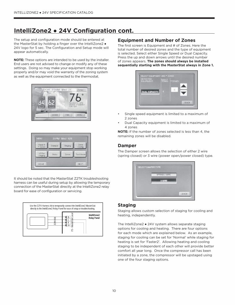
Zoning by Use and OccupancyFor a typical residence, different rooms in the house are used or occupied at different times during the day. A typical single story home has three bedrooms, a kitchen, a living room , a dining area, bathroom(s), and a family room as shown below in Figure 1.
Never place more than one zone in a single room. Notethat the type of use in each room or group of similarly used rooms determines the assigned zone. Figure 1 illustrates a four zone example of zoning by use.
The kitchen, dining, living, family, and utility rooms areexcellent choices for a separate zone because they are commonly occupied during the same time of day and share common exposures. IntelliZone2 ● 24V will provide more conditioned air to these areas when they are in use and less to other areas of the house when unoccupied.
It is doubtful that the living room, family room, kitchen, and bedrooms will all be occupied at the same time. For most of the year, the family room will be occupied at different times of the day than the living room and bedrooms.
The master suite and bedrooms should almost always be on separate zones than the main living areas because each area tends to be occupied at different times. Obviously, bedrooms are usually occupied during the night, not during the day when the living area of the house is occupied. With IntelliZone2 ● 24V, the bedrooms can be “setback” during the day and the main living areas “setback” at night. This allows the HVAC equipment to concentrate on the kitchen and living areas when occupied and on the bedrooms at night when the rest of the house may be unoccupied.
A feature in a residence which can dictate zoning is multiple stories or floors. In a two story structure, the upper and lower floors will have different heating or cooling demands. These differences can be attributed to heat migration (the tendency of heat to rise), types of use, occupancy, and the roof heat load.
Another example is a small doctor’s office. The zones to consider would be the waiting room, patient rooms, lab,and office areas. The waiting room is an excellent zonebecause the number of people will vary during the day; usually, an exterior door is opened frequently, and these rooms require large amounts of air for ventilation.
Patient rooms are another good choice for a zone; usually occupied by one to three people with tight requirements on temperature needed to ensure comfort. A lab or similar area could be a separate zone because of the different type of use as compared to the rest of the building.Other good commercial candidates might include small to medium size dentist offices, retail stores with employee lounges and offices, general commercial offices with computer rooms or conference rooms, car dealerships with show rooms, general offices, and parts rooms.
Zoning by Outside ExposureZoning by the exterior exposure considers the time of day when the peak cooling and heating loads occur. Zoning by exterior exposure should be considered when the following two conditions exist:
1. There are distinctly different rooms or areas along the south and west exposures, and the building has a large area of glass on those exposures. An example is a room where over half of the cooling load is due to transmission through the glass alone.
2. There are a relatively small number of people in the building and a small number of people occupying offices or spaces along the south or west sides of the building. In short, the heat gain due to people and the ventilation required for the occupants is small when compared to the overall cooling requirements for the building.
Zoning by exposure is not the normal method of zoning for most residences. The exceptions to this rule are rooms along the south or west which have large amounts of glass. Generally bedrooms on the southwest exposure require similar levels of heating or cooling because the time of use precludes heat gain from the sun as a major factor in occupant comfort. Exceptions include large windows or other features.
Using the zoning by exposure method in an office can be more difficult than in a home. If the predominant load in the building is people, the IntelliZone2 ● 24V should follow the major occupancies in the building as determined by the occupants. If there are few people in the building, then zoning by exposure becomes prevalent since the heat load applied to the individual offices or rooms is dominated by the exposure and time of day. In all cases, judgement is required due to variations in climate, floor plan, type and time of use, glass areas, and glass orientation.
If still unsure which areas or offices to place in a particular zone, the best method is to use load calculations such as ASHRAE or another reliable method. Once this is done, compare the hours to peak load (both heating and cooling) and group offices together that have approximately the same time of day for the peak loads.
20
INTELLIZONE2 ● 24V SPECIFICATION CATALOG
Zone Selection cont.
IntelliZone2 Design Software
General Zone Selection Rules• Minimum of three branch runs per zone.• Zone together areas of like uses, but separate areas
based on differing uses• Avoid grouping rooms of different levels or floors into the
same zone.• Avoid grouping rooms with opposite sun or weather
exposures in the same zone.
NOTE: Ensure zone duct is designed to handle cfm required
Locating the ThermostatsThe thermostats must be located in the room or zone that
each controls. Locate a thermostat about five feet above
the floor. Do not locate a thermostat where it may be
exposed to direct sunlight, drafts or direct supply air. Do
not place a thermostat on an outside wall. Follow the same
guidelines that apply with standard thermostat installation.
If two or more rooms are on a single zone, locate the
thermostat in a hallway or area where it can sense the
return air from all rooms.
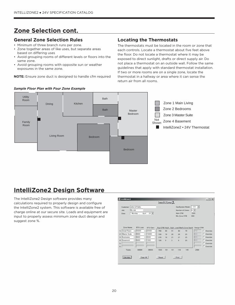
The IntelliZone2 Design software provides many
calculations required to properly design and configure
the IntelliZone2 system. This software is available free of
charge online at our secure site. Loads and equipment are
input to properly assess minimum zone duct design and
suggest zone %.
Sample Floor Plan with Four Zone Example
MasterBedroom
Bath
Bedroom
Bedroom
Kitchen
Living Room
UtilityRoom
Dining
Zone 2 Bedrooms
Zone 1 Main Living
Zone 3 Master Suite
Zone 4 Basement
IntelliZone2 • 24V Thermostat
NotShownFamily
Room
Bath

21
INTELLIZONE2 ● 24V SPECIFICATION CATALOG
Special Zoning Applications
ResidentialUnfinished Basement
• Return air ducts are required to all zones.• Careful design of ductwork, including return air, for future
finishing is crucial.• Insulated basements, in general, require very little space
conditioning. However, the floor space can be substantial. To provide adequate air movement, more air flow will be required than the space conditioning load would indicate.
• In the North, an unfinished basement can be difficult to raise above 65° F in the winter due to its large mass of exposed concrete and typically minimal supply and return ductwork. In the summer, damper leakage occurring from cooling calls in other zones, along with cool basement temperatures, can actually produce a heating call in the basement. Use a “cooling only” mode on the basement zone thermostat in the summer If this becomes an issue.
• Continuous blower selection on the zone thermostat can help circulate some of the cooler air to other zones in the
summer and help dehumidify the basement area.
Open Entry/Stairwell in a Multi-Story Home
• Large open areas between two floors allow a tremendous volume of air to rise to the upper floor causing overheating in the winter and undercooling in the summer. Although running a continuous blower can help recirculate the air between floors, a zone system will provide the conditioning exactly to the zone that needs it. Be careful that the system doesn't cool the upper level
while heating the lower level in the winter.
Garage, Unused or Unconditioned Zone
• Conditioned garages should be insulated and sealed as tightly as possible to avoid excessive energy use. Although a dedicated space conditioning unit installed specifically for the garage is the best choice, this is not always possible. If the garage zone is being conditioned by the main system, typically only the supply air is ducted. The thermostat setpoints, and thus the amount of supply air, should be limited to avoid increasing air infiltration to the home due to the negative pressure. Main unit return air ducts are not allowed by most building codes due to the chance of recirculating fumes from the garage throughout the home.
• Unused zones can include guest bedrooms. Unconditioned zones may include unfinished areas. Both of these represent areas in which reduced setpoints are desired to limit energy use. In these zones, a continuous blower speed should not be selected. Due to the common return system with other zones, the setpoint should be no more than 4° F off from other zone setpoints. If a larger setback is desired, a return duct damper system should be installed in the zone to
more fully isolate the zone from the rest of the home.
In combination with return air dampers in scenarios
where large setbacks or unconditioned zones are desired
that zone must also be isolated from the conditioned
structure with doors, partitions, etc. to avoid air mixing.
Small Zone
• If a group of rooms is zoned but constitutes less than
25% of the total system load, the duct system needs
to be designed to handle the minimum 25% of the
system air flow (25% in dual and 50% in single-speed
equipment). For example, an 049 system (1500 cfm max
and 600 cfm minimum) would have a minimum design
zone of 375 cfm (25% x 1500 cfm = 375 cfm). When
this zone calls, the unit will push 700 cfm through the
ductwork designed for 375 cfm. Although higher velocity
will be encountered here, the noise level and throw
should not be objectionable or even noticeable. This also
eliminates the need for a bypass damper. A minimum of
three branch runs should be employed in any zone to
limit the effects of one branch duct being blocked by
shoes, furniture, etc.
Sun Room
• A sunroom can present a tremendous cooling load and
will likely require a higher cooling setpoint. Such rooms
represent areas in which reduced setpoints would be
desired to limit energy use. In these zones, continuous
blower should not be selected and, due to the common
return system with other zones, the setpoint should be
no more than 4° F off other zone setpoints. If a >4° F
setback is desired, a return duct damper system should
be installed in the zone to more fully isolate it from the
rest of the home.
CommercialConference Room/Office
• Frequently, conference room(s) and office(s) are grouped
together on the same zone due to the direction of
exposure. However, when a closed-door conference is
held with 12 people, it frequently becomes uncomfortable
for either the conference room occupants or one of the
office occupants (due to the tremendous difference in
loads present within the zone). Here, zoning can solve
the problem easily by providing the exact cooling where
and when needed.

22
INTELLIZONE2 ● 24V SPECIFICATION CATALOG
Peak Heating and Cooling Demands
Cooling-Dominated StructuresIn cooling-dominated structures such as commercial
buildings and southern residential homes (where electric
heat is rarely needed as an auxiliary heat source), up to
five load calculations need to be performed. Commercial
hourly peak load calculations on all of the four zones under
control of the IntelliZone2 ● 24V System are required. This
information sizes the supply air ductwork and the zone
damper properly. The fifth load is the entire building (all four
zones). Why perform this step? Because the different zones
have different times of day when they need peak cooling or
heating. The actual peak cooling or heating load is usually
less than the sum of the peak loads for the four zones.
The load calculation for the entire structure is used to size
the HVAC equipment only. Ductwork branches and zone
dampers are sized using the peak zone conditions for each
particular zone. The difference between the sum of the
peak loads for the individual zones and the peak load for
the entire building is called “diversity”.
Diversity is a measurement of the effective cooling or
heating capacity added to the system due to zoning. The
physical heating or cooling capacity is not increased, but
because it is more effective, HVAC equipment can be
sized smaller using zoning diversity. This represents the
first cost savings of the IntelliZone2 ● 24V Comfort Zoning
System. Secondary savings are attributed to the lower
operating costs.
Many popular software packages or HVAC residential
loads now calculate peak zone loads; check your software
package for its capability.
Heating-Dominated StructuresIn heating-dominated structures, such as northern
residential homes (where units are generally sized with
a small amount of electric heat installed as an auxiliary
heat source), diversity may be present in cooling; however,
the unit size is dictated by the heating load and diversity
is rarely present. In this application, a simple room-by-
room or zone-by-zone analysis can be performed with the
resultant sum of the rooms or zones taken as the whole
house load. The table below lists the four zone loads of this
example home.
NOTE: Dual Capacity unit has a 70% low capacity output,
therefore minimum cfm required per zone is 40% of
nominal cfm.
Example Four Zone Load Summary
Htg Btu/h
Htgcfm
Total Clg
SensClg
Clgcfm
Maxcfm
Adjusted100% cfm
Min cfmReq’d.
Designcfm
# ofBranch
Actualcfm %
ActualLoad %
ZoneDIP %
Zone 1 Main Living
Kitchen 2259 73 3128 2400 145 145 118 1
Family 4264 138 6660 5128 311 311 252 2
Utility 3002 97 1614 1243 75 97 78 1
Living/Dining 6351 205 7158 5511 334 334 271 3
Total 15876 512 18560 14282 866 887 718 600 718 29% 34% 45%
Zone 2 Bedrooms
Bdrm 1 3224 104 1939 1752 106 106 240 2
Main Bath 892 29 284 407 25 65 147 1
Bdrm 2 2708 87 1692 1550 94 94 213 1
Total 6824 220 3915 3709 225 265 215 600 600 24% 15% 45%
Zone 3 Master Suite
Mstr Bdrm 2806 91 2294 1766 107 107 351 2
Mstr Bath 2350 76 1504 1158 70 76 249 1
Total 5156 166 3798 2924 177 183 148 600 600 24% 11% 45%
Zone 4 Basement
Total 19123 617 5007 3967 240 517 419 600 600 4 24% 41% 45%
Total Zones 46979 1515 31280 24882 1508 1852 1500 2518
Total House 46290 @ 70°F 32822 @ 20°F 123% 100% 168%
Unit DataNom Hi cfm Min Lo cfm 40% Nom cfm
Model
049 1500 1350 600

23
INTELLIZONE2 ● 24V SPECIFICATION CATALOG
System Sizing
HVAC EquipmentThe HVAC equipment size should always be determined by
performing a load calculation on the entire building or the
area of the building that will be serviced by the equipment.
Most of the time, this peak load will be less than the sum
of the peak loads from the four zones. Remember that
each of the peak loads for the individual zones will usually
occur during different times of the day. The building peak
load or “block” load takes this into account and is the most
accurate means of sizing the HVAC equipment. Performing
load calculations helps eliminate much of the guesswork
involved with equipment sizing.
TransformersProviding adequate transformer power (VA) to supply
the system is an important requirement. Each IntelliZone2
3-wire damper requires 3.0VA at nominal voltage (7.0VA
for 2-wire). The standard available transformer is a 75VA
with circuit breaker (Part # ZTK240). The Transformer 'VA'
Calculation table shows a sample sizing procedure that
should be carried out for each installation. If the total VA
is greater than 75VA, then a second transformer should
be wired in parallel to provide a total power capability of
150VA. Maximum recommended dampers are 12.
Transformer ‘VA’ Calculation (3-wire actuator)
Zone 1 Dampers Power to 2 IZ2 Dampers 6.0 VA
Zone 2 Dampers Power to 1 IZ2 Dampers 3.0 VA
Zone 3 Dampers Power to 2 IZ2 Dampers 6.0 VA
Zone 4 Dampers Power to 3 IZ2 Dampers 9.0 VA
Total VA Draw 24.0 VA
Ductwork If the installed ductwork is not large enough to handle
the peak zone loads, the HVAC system will fail to maintain
comfort in these zones. This will defeat the purpose of
the IntelliZone2 ● 24V System. An analogy to this is the
water supply piping to a residence. In many cases, the
pipe supplying the entire home is a one-inch diameter
pipe. This pipe supplies all of the lavatories, showers, tubs,
kitchen, spigots, and clothes washer. There may be three
outdoor spigots and two showers in the house, but virtually
never are the pipes to these devices found to be less than
1/2-inch diameter. Once again, the reason is diversity. The
HVAC ductwork must be sized properly so when any one of
the IntelliZone2 ● 24V System's zones demands capacity,
the ductwork has the ability to supply it. Using the
IntelliZone2 Design software can help limit the ductwork
oversizing.
Supply Ductwork
When sizing the supply air system and the return air
system (if applicable), the diversity used to size the HVAC
equipment plays a role here as well. The supply air duct-
work should be of sufficient size to handle the HVAC air
handler cfm before any branching occurs. After branching
the ductwork to one or more of the zones, the supply or
return air ductwork cannot be reduced in size to the extent
that normally would be expected in a HVAC system. The
reason is the diversity and peak zone.
NOTE: Dual Capacity unit has a 70% low capacity output,
therefore minimum cfm required per zone is 40% of
nominal cfm.
IntelliZone2 ● 24V CFM Design
Capacity ModelMaxCFM
Zone Design CFM
CFMPercentage
Single Speed
030 1000 700 50
036 1200 850 50
042 1300 900 50
048 1500 1000 50
060 1800 1100 50
070 2000 1100 50
Dual Capacity
024/026 800 600 40
036/038 1200 600 40
048/049 1500 800 40
060/064 1800 950 40
072 2000 1100 40
Return Ductwork
Return air ductwork should be adequate in each zone
to return the same amount of air delivered to the zone.
In certain rooms, returns are not allowed by code or not
desirable (kitchens and baths, respectively). Returns in other
rooms in that zone should be sized larger to compensate.
General Rules:
• Minimize the number of dampers and plan to install the
dampers as close to the main trunk as possible to limit
duct leakage. CAUTION: When installing the IntelliZone2
● 24V in a structure with fossil fuel (oil, gas, propane)
appliances, it is important that both supply and return
dampers are used in each zone to avoid potential
backdrafting of fossil-fueled appliances.
• The IntelliZone2 Design software should be used to aid in
the selection and calculation of design cfm.

24
INTELLIZONE2 ● 24V SPECIFICATION CATALOG
System Sizing cont.Four Zone Ductwork Example (Delivery cfm)
MasterBedroom
Bath
Bath
Bedroom
Bedroom
Kitchen
Living Room
FamilyRoom
UtilityRoom
Dining ToBasement
DamperSupply Ductwork
78 90 118 249 175
120
120
2139090
147600
126
126175
General Installation Guidelines General rules to follow when installing a zone system:
CAUTION: When installing the IntelliZone2 ● 24V in a structure with fossil fuel (oil, gas, propane) appliances, it is important that both supply and return dampers are used in each zone to avoid potential backdrafting of fossil-fueled appliances.
• Up to four zones with dual capacity (two with single-
speed units)
• All dampers should be located as close to the main trunk
as possible to limit the amount of pressurized trunkline
and thus limit air leakage.
• No less than three branch runs in a zone to prevent a
single branch obstruction (curtains or clothes etc.) from
affecting unit airfow.
• Insulate and seal around rectangular dampers to
prevent leakage.
• All dampers must be wired with 18-gauge wire. (Note:
Crimp connections should never be used on solid
conductor wire.)
• Ensure that the transformer can handle the power
requirements of the system.
• No more than three dampers per zone.
• Ductboard-mounted dampers should be supported
within six inches of the damper due to the weight and
stress on the ductboard.

25
INTELLIZONE2 ● 24V SPECIFICATION CATALOG
IntelliZone2•24V with SAH Air Handler

26
INTELLIZONE2 ● 24V SPECIFICATION CATALOG
IntelliZone2•24V Split OperationFor the split system to be compatible with IntelliZone2 there must be either an ABC or Premier controls in the compressor section.
Upon a call (or calls) from the zones, the IntelliZone2 “weighs” each zone based upon two components: 1) the level of call (Y1, Y2, Y3) coming from the zone; and 2) the size of the zone (zone % selected). This gives a very accurate picture of not only overall heating or cooling requirements (as in other control methods), but also how much heating or cooling is really required for each separate zone.
This, in turn, defines how much compressor (1st or 2nd stage), blower and auxiliary heat should be engaged for each particular situation. The result is a system that utilizes lower compressor speed more often for improved comfort and energy savings, while relying upon auxiliary heat less often for more energy savings than non-zoned systems.
Heating, Unit 1st stage (Single/Dual Capacity Compressor and 5-Speed ECM)
Operation as stated above with separate zone call levels of YI, Y2, and W being translated into unit call 1st stage (Y1). Blower speed will be the ‘Y1’ setting of the 5-Speed ECM
which is set at the motor.
Heating, Unit 2nd stage(Single/Dual Capacity Compressor and 5-Speed ECM)
Operation as stated above with separate zone call levels of YI, Y2, and W being translated into unit call 2nd stage (Y1, Y2). Blower speed will be the ‘Y2’ setting of the 5-Speed
ECM which is set at the motor.
Heating, Unit 3rd Stage(Single/Dual Capacity Compressor and 5-Speed ECM)
Operation as stated above with separate zone call levels of YI, Y2, and W being translated into unit call 3rd stage (Y1, Y2, W). Blower speed will be the ‘W’ setting of the 5-Speed ECM which is set at the motor.
Cooling, Unit 1st stage(Single/Dual Capacity Compressor and 5-Speed ECM)
Operation as stated above with separate zone call levels of YI, Y2, and O being translated into unit call 1st stage (Y1, O). Blower speed will be the ‘Y1’ setting of the 5-Speed ECM which is set at the motor.
Cooling, Unit 2nd stage(Single/Dual Capacity Compressor and 5-Speed ECM)
Operation as stated above with separate zone call levels of YI, Y2, and O being translated into unit call 2nd stage (Y1, Y2, O). Blower speed will be the ‘Y2’ setting of the 5-Speed ECM which is set at the motor.
Description of Operation - Split System

27
INTELLIZONE2 ● 24V SPECIFICATION CATALOG
Description of Operation - Split System cont.Emergency HeatEmergency heat mode may be engaged by selecting at the MasterStat. All zone thermostat fault LED's begin to flash two quick flashes, followed by a pause, indicating that emergency heat mode has been activated. The temperature of the structure will be controlled by the zone 1 MasterStat while other zones are ignored. When a demand for heat occurs at the MasterStat all zone dampers are opened and emergency heat is energized. Emergency heat will continue to operate until the MasterStat demand is satisfied.
Emergency heat mode may be exited by selecting OFF (or one of the other mode selections) at the MasterStat, as well as all zone thermostat fault LED's stop flashing, indicating emergency heat mode has been deactivated and normal IntelliZone2 operation may resume.
Continuous BlowerAll dampers are open and the unit's blower will be operated while heating or cooling is suspended for any zone(s) selected for continuous blower operation at the zone thermostat. Upon any heating or cooling call to the unit, all continuous blower operation ceases.
Lockout Mode(Single/Dual Speed Compressor)
During the unit lockout mode, the appropriate Fault code will be communicated to the MasterStat and the blower will operate continuously. If the collective zones translate into a > 24% heating call, emergency heat operation will
occur and all zone dampers will open. Blower speed will be
highest selected speed setting at the heat pump.
28
INTELLIZONE2 ● 24V SPECIFICATION CATALOG
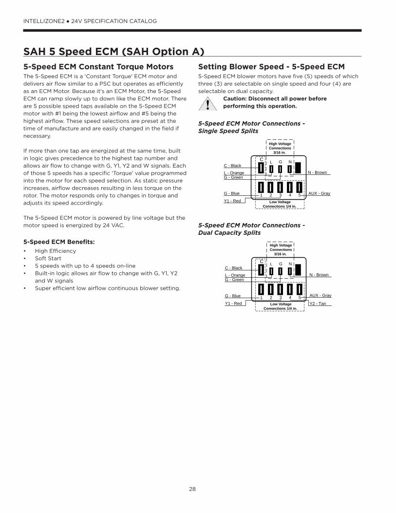
SAH 5 Speed ECM (SAH Option A)5-Speed ECM Constant Torque MotorsThe 5-Speed ECM is a 'Constant Torque' ECM motor and
delivers air flow similar to a PSC but operates as efficiently
as an ECM Motor. Because it's an ECM Motor, the 5-Speed
ECM can ramp slowly up to down like the ECM motor. There
are 5 possible speed taps available on the 5-Speed ECM
motor with #1 being the lowest airflow and #5 being the
highest airflow. These speed selections are preset at the
time of manufacture and are easily changed in the field if
necessary.
If more than one tap are energized at the same time, built
in logic gives precedence to the highest tap number and
allows air flow to change with G, Y1, Y2 and W signals. Each
of those 5 speeds has a specific 'Torque' value programmed
into the motor for each speed selection. As static pressure
increases, airflow decreases resulting in less torque on the
rotor. The motor responds only to changes in torque and
adjusts its speed accordingly.
The 5-Speed ECM motor is powered by line voltage but the
motor speed is energized by 24 VAC.
5-Speed ECM Benefits:
• High Efficiency
• Soft Start
• 5 speeds with up to 4 speeds on-line
• Built-in logic allows air flow to change with G, Y1, Y2
and W signals
• Super efficient low airflow continuous blower setting.
Setting Blower Speed - 5-Speed ECM5-Speed ECM blower motors have five (5) speeds of which
three (3) are selectable on single speed and four (4) are
selectable on dual capacity.
Caution: Disconnect all power before performing this operation.
L G NC
High VoltageConnections
3/16 in.
1 2 3 4 5G - Blue
Y1 - Red
AUX - Gray
C - Black
L - OrangeG - Green
N - Brown
Low VoltageConnections 1/4 in.
L G NC
1 2 3 4 5 AUX - GrayG - Blue
Y1 - Red Y2 - Tan
C - Black
L - OrangeG - Green
N - Brown
High VoltageConnections
3/16 in.
Low VoltageConnections 1/4 in.
5-Speed ECM Motor Connections - Single Speed Splits
5-Speed ECM Motor Connections - Dual Capacity Splits

29
INTELLIZONE2 ● 24V SPECIFICATION CATALOG
Wiring SchematicSplit Units
75VA kit mounted in heat pump
A+
R
C
B-
P11 –
Zon
e 1Ma
sterS
tat
A+
R
C
B-
P12 –
Zon
e 2
A+
R
C
B-
P13 –
Zon
e 3
A+
R
C
B-
P14 –
Zon
e 4
A+
R
C
B-
P15 –
Zon
e 5A+
R
C
B-
P16 –
Zon
e 6
A+
R
C
B-
P3 –
Maste
rStat
Loca
l
C
B-
A+
R
P17 –
Hea
t Pum
p
NO NO
NCCom
Close
Zone 1 Dmpr
Open
P5
NO NO
NCCom
Close
Zone 2 Dmpr
Open
P6
NO NO
NCCom
Close
Zone 3 Dmpr
Open
P7
NO NO
NCCom
Close
Zone 4 Dmpr
Open
P8
NO NO
NCCom
Close
Zone 5 Dmpr
Open
P9
NO NO
NCCom
Close
Zone 6 Dmpr
Open
P10
LAS – Outdoor Air Sensor
P1
G G G
RR B Y
G G G
Zone 1
Zone 2
Heating Cooling
Zone 3
Zone 4 Zone 6
Zone 5
FanAlarm/Status
R
C
P18Damper Power
F1 DamperFuse
IntelliZone2 Relay Board
DX+
R
C
DX-
Zone
1Ma
sterS
tat
IntelliZone2 MasterStat
A+
R
C
B-
Zone
3 St
atOn32 1
Zone 3 code shown
A+
R
C
B-
Zone
5 St
atOn32 1
Zone 5 code shown
IZ2 ZoneStat
IZ2 SensorStat
MasterStat is always Zone 1
Conversion Module
ABC in Compressor
Section
Split Heat Pump
For Temporary Config or T-ShootZ2TK Kit
Damper Transformer
24V
Blue – 240V
Black - Com
Red – 208V
2-Wire Damper
1-Com
2-Close
3-Open
Drive Close/Spring Open
Drive Open/Drive Close
3-Wire Damper
Zone ID must be set for each Zone 2-6. ID can be confirmed on ZoneStat by pressing cancel button for 5 sec. ID shown on display. See Fig 1.
Zone ID must be set for each Zone 2-6. ID cannot be confirmed on Zone Sensor Stat. See Fig 1.
TSU02Optional Outdoor
Temp Sensor
YellowBlack/White
5A Fuse
Light emitting diode - Green
Polarized connector
Low voltage wiring
Internal junction
Fuse
Legend
Relay Contacts-N.O., N.C.
G
132PScrew Terminal Strip
Com
Close
Open
On32 1
On32 1
On32 1
Zone 4 Zone 5Zone 3On
32 1
Zone 2On
32 1
Zone 6
Fig 1 - Zone ID Codes
- MasterStat always Zone 1. Zone ID not necessary.
-Zone ID must be set for each Zone 2-6. ID can be confirmed on ZoneStat bypressing cancel button for 5 sec. ID shown on display.
NOTES:
-Small screw driver can be used to set ID thru protective plastic skin!
C
R
DX-
DX+
Wire nut
1-Com
2-Close
S1
S2 Optio
nal
Remo
te Se
nsor
Ther
mosta
t
YGW
W2Y2
O
RC
OLo
GY1Y2
W
CR
P8
L
On321
Zone 5On
32 1
Zone 6
Zones 5 and 6 are not applicable with the IntelliZone2 • 24V System
F2 Relay Board Fuse
3A Fuse
Microprocessor and other
ComponentsNote: Shorting a
thermostat R/C input will blow the ABC fuse not this fuse
Harness Supplied with IZ2 then wire nut to conversion
module

30
INTELLIZONE2 ● 24V SPECIFICATION CATALOG
Wiring Schematic cont.Split Units AXB and 5 Speed ECM
CFM
P13
P4
SW1
P5JW2
P9
LO
O/B
Y2WDH
P8 P7
RS485 NET RS485 NET
P6
RS485 EXP
P3
SW2
On
Future Use L Output Type
CC – Dual/SingleAcc – Dip 5Acc – Dip 4
RV – B/OFP2 – 15°F/30°FFP1 – 15°F/30°F
Com1LED5
Com2LED5
Test Mode
F1-3A
P1
C
PWM
12345678
ALMALGACC COMACC NOACC NC
RC
GY1
EH2CEH1CCOC R - +C R - +
Off
FaultLED1
R
StatusLED3
ConfigLED2
CC2 CC F C R F FG CC CCGCC2HI
CC2LO
CC2G REV REV FP1 FP1 FP2 FP2 LPS LPS HPS HPS
Aurora Base Control(ABC) in Compressor Section
K1-RV Relay
K2-CC Relay
K3-CC2 Relay
K4-Fan RelayK5-Alarm Relay
K6-Acc Relay
F
R
C
CCGY1C
R
ESLS
P2
EH1
YG G
G
To TB RTo TB C
To TB W1
To TB Y2
To TB Y1
To TB G
Conversion Module
C
R
DX-
DX+
Thermostat
YGW
W2Y2
O
RC
P8
LC
B-P17 –
Hea
t Pum
p
IntelliZone2 Relay Panel
A+
R
Harness Suppliedwith IZ2 then wirenut to conversion
module

31
INTELLIZONE2 ● 24V SPECIFICATION CATALOG
GL2L1
208-230/60/1
Light emitting diode - Green
208-230V Relay coil
Electric Heat Contactor
Polarized connector
Factory Low voltage wiringFactory Line voltage wiringField low voltage wiringField line voltage wiringOptional blockDC Voltage PCB tracesInternal junctionQuick connect terminal
Thermal Limit Switch
Field wire lug
Ground
HE -
PB -
Heater element
Power block
Legend
N.O., N.C.
G
L1
ER1 to ER4 - Aux heat stage relays
1 2 3P
EHC
EHC
Breaker
TS
Notes:1 – To operate in 208V mode replace the blue transformer wire connected to PB-L2 with red transformer wire.
2 – Low voltage wiring CLASS 2.
SAH Air Handler Section
Transformer
Blk/WhYellow
24V
L2L1
PB
Black
Blue
Red NOTE 1 Orange
Brown
1
2
3
L N G
5 SpeedECM
BlowerMotor
C
4
5
O
C
Y1
G
S
W1
L
X2
X1
R
Y2
TB
Black
Blue
Red
Tan
Grey
`
Wiring Schematic cont.Split Units AXB and 5 Speed ECM

32
INTELLIZONE2 ● 24V SPECIFICATION CATALOG
Notes

33
INTELLIZONE2 ● 24V SPECIFICATION CATALOG
Revision Guide
Pages: Description: Date: By:
Misc. Updated Schematics, Added new Air Handler information 10 Apr 2017 JM
Misc. Updated, Added TPCC32U01 and SensorStat 14 Dec 2016 MA
All First Published 12 Mar 2015 MA

SC1678EW 05/17
Product: IntelliZone2
Type: Comfort Zoning System
Size: Four Zone Capability
Document: Specification Catalog and Design Guide