COMMANDER TX2100 for INDUSTRY - gasdetekcija.rs · • The Trolex team of system design engineers...
167
P R O D U C T I N S T A L L A T I O N & O P E R A T I N G D A T A C O N T R O L & D I S P L A Y TROLEX LIMITED Newby Road Hazel Grove, Stockport, Cheshire SK7 5DY, UK. +44 (0)161-483 1435 [email protected] www.trolex.com tel: e-mail: internet: 1 I N S T A L L A T I O N & O P E R A T I N G D A T A COMMANDER TX2100 for INDUSTRY of 170 ISSUE F: 12/06 Further copies of this document are available from trolex.com
-
Upload
hoangquynh -
Category
Documents
-
view
220 -
download
1
Transcript of COMMANDER TX2100 for INDUSTRY - gasdetekcija.rs · • The Trolex team of system design engineers...

P R O D U C T
I N S T A L L A T I O N & O P E R A T I N G D A T A
C O N T R O L & D I S P L A Y
TROLEX LIMITEDNewby Road
Haze l Grove, Stockport ,Chesh i re SK7 5DY, UK.
+44 (0)161-483 1435sa les@tro lex .comwww.tro lex .com
t e l :e - m a i l :i n t e r n e t :
1
I N S T A L L A T I O N & O P E R A T I N G D A T A
COMMANDER TX2100for INDUSTRY
of 170 ISSUE F: 12/06
Further copies of this document are available from
trolex.com
2 of 165
P R O D U C T
ISSUE F: 12/06
I N S T A L L A T I O N & O P E R A T I N G D A T A
C O N T R O L & D I S P L A Y
T X 2 1 0 0
PART 1
PART 2
PART 3
Page
commander
1 Commander Profile 4
2 TX2101 Command Module 9
3 TX2102 Terminal Module 14
4 TX2141 Channel Cards and Accessories 21
5 TX2131 Commandbus Convertor ModuleTX2121 Commandbus Repeater Module 47
6 Power Supplies 60
7 NOT USED
8 Commandbus Cables 63
9 Navigator Map 66
10 Readout Zone 68
11 Security Barrier 73
12 Setup Zone 75
13 Special Control and Monitoring Functions 137
14 Adding an Operator Interface or PC 139
distr ibuted commander systems
15 Data Communications 141
16 NOT USED
assembling systems 143
17 System Planning 147
18 Which Channel Card? 155
19 Conformity Check 163
20 Approvals and Certification 165

3 of 165
P R O D U C T
ISSUE F: 12/06
I N S T A L L A T I O N & O P E R A T I N G D A T A
C O N T R O L & D I S P L A Y
T X 2 1 0 0
PART 1 c o m m a n d e r

P R O D U C T
ISSUE F: 12/06
I N S T A L L A T I O N & O P E R A T I N G D A T A
C O N T R O L & D I S P L A Y
T X 2 1 0 0
PART 11. COMMANDER
PROFILE
4 of 165
1 commander prof i le
SENSOR INPUTS
CONTROL OUTPUTS
SENSOR INPUTS
CONTROL OUTPUTS
COMMAND MODULE TERMINAL MODULE TERMINAL MODULE
I/O FIELD TERMINALS I/O FIELD TERMINALS
COMMANDBUS COMMANDBUS
LOCAL AREANETWORKDATACOMMS

P R O D U C T
ISSUE F: 12/06
I N S T A L L A T I O N & O P E R A T I N G D A T A
C O N T R O L & D I S P L A Y
T X 2 1 0 0
PART 11. COMMANDER
PROFILE
5 of 165
I/O COMMAND AND CONTROL SYSTEM FOR
SENSORS, CONTROL DEVICES AND ALARMS
Modular Bus Configuration for simple compilation of local monitoring and
control systems or large scale distributed Minewide monitoring installations.
•••••••••••••••• Bus expandable I/O up to a possible maximum of 960 addresses:
analogue inputs, pulse/frequency inputs, switch inputs, output
switching, analogue output control.
•••••••••••••••• User Configurable input signals and output drivers by simple channel
card insertion.
••••••••••••••• Programmable sensor response functions.
•••••••••••••••• Programmable monitoring and control functions.
•••••••••••••••• Data logging, up to 4000 readings for each I/O.
•••••••••••••••• Datacomms for distributed Minewide systems.
•••••••••••••••• Bus architecture for minimal cabling and wiring connections.
•••••••••••••••• Easy-to-use direct input programming through the navigator keypad.
Complete versat i l i ty of sensor and control device management with a vast
range of operating opt ions giv ing unparal le led s impl ic i ty of appl icat ion.

P R O D U C T
ISSUE F: 12/06
I N S T A L L A T I O N & O P E R A T I N G D A T A
C O N T R O L & D I S P L A Y
T X 2 1 0 0
PART 11. COMMANDER
PROFILE
6 of 165
1 . 1 AREA APPL ICAT ION
GENERAL PURPOSE APPLICATION
• General Purpose industrial applications operating at 24V dc supply.
• Sensors and control devices are generally 24V dc supply.
SERIES
.03

P R O D U C T
ISSUE F: 12/06
I N S T A L L A T I O N & O P E R A T I N G D A T A
C O N T R O L & D I S P L A Y
T X 2 1 0 0
PART 11. COMMANDER
PROFILE
7 of 165
1 .2 COMMANDER PROFILE
DESIGN INTEGRITY
Operational safety to eliminate the possibility of incorrect plant output for a given input state is
largely dependent upon correct software operation. Commander is designed within rigorous quality
control techniques to ensure maximum reliability.
CHECKING AND SYSTEM MONITORING.
• All system communications links incorporate error checking and retry routines.
• All processor functions are ‘watchdogged’ against malfunction.
• Built-in self-test routines implement functional checks on all systems at system bootup, prior to
permitting outputs to be changed under software control.
• All outputs are held in hardware-defined default states until all systems have been validated and will
retain the ‘last command’ condition.
• Wherever practicable all input and output circuits are continuously monitored for short circuit and
open circuit conditions. Output control relays have failsafe configuration. Fault conditions identified
are individually alerted on the Command module and selective alarms can be initiated.
SYSTEM INTEGRITY
High levels of system security can be configured into a Commander system by adopting various design options.
• All I/O channel cards can be individually replaced without interrupting the normal function of the
system.
• Additional I/O channel cards can be added without interrupting the normal function of the system.
• Input command signals can be ‘voted’ in any combination and I/O channels can be ‘paralleled’ for
added security.
• Dual power supplies may be connected onto the Commandbus for standby failure protection where
safety parameters permit.
Commander is a software-based system and relies on a single communications backbone and non-
redundant processors. Safety critical installations where system multiple redundancy is required, must
be combined with systems incorporating hard-wired safety circuits to provide redundancy capacity.

P R O D U C T
ISSUE F: 12/06
I N S T A L L A T I O N & O P E R A T I N G D A T A
C O N T R O L & D I S P L A Y
T X 2 1 0 0
PART 11. COMMANDER
PROFILE
8 of 165
SAFETY INTEGRITY
• All modules and elements of the Commander system are
individually coded to prevent incompatible or unsafe
combinations.
• All Commander modules and their combinations are
manufactured in compliance with European EMC protection
requirements for both radiated and received electromagnetic
influence.
DIAGNOSTICS
Protected access is available to built-in menu based fault
diagnostics. Various levels of software and function routines can be
examined in detail for system analysis.
Access is also available to comms monitoring
intelligence data.Diagnostics
Entry into these facilities is protected by an individual security keycode. This is available, together
with user information, from the Trolex Commander application department.
TECHNICAL SUPPORT AND TRAINING
• The Trolex team of system design engineers is available to assist
with Commander applications. Alternatively, we can design and
configure a complete functioning system including sensors,
software and final commissioning to specification.
COMMANDER TRAINING
One day training courses in Commander applications including a free Commander
Configuration Software Package and hands-on practical system design examples.
CONTACT
HELPLINE
+44 161 285 8866

P R O D U C T
ISSUE F: 12/06
I N S T A L L A T I O N & O P E R A T I N G D A T A
C O N T R O L & D I S P L A Y
T X 2 1 0 0
PART 12. TX2101
COMMANDMODULE
9 of 165
2 TX2101command module

P R O D U C T
ISSUE F: 12/06
I N S T A L L A T I O N & O P E R A T I N G D A T A
C O N T R O L & D I S P L A Y
T X 2 1 0 0
PART 12. TX2101
COMMANDMODULE
10 of 165
The COMMAND MODULE is the hub of the Commander System.
A powerful data processor with a graphical data display, data
communications and navigator programming.
••••••••••••••• Standard rail mounting modules to DIN 43 880
or panel mounting option.
••••••••••••••• Commandbus communications to field I/O Terminal Modules
up to a possible maximum of 960 I/O.
••••••••••••••• Power distribution through the Commandbus:
••••••••••••••• Navigator keypad for convenient direct user programming of
all functions:
• Sensor input signal response characterisation.
• Control output driver characteristics.
• Data logging.
• System diagnostics.
••••••••••••••• Graphical LCD readout:
• Sensor input signal display with selectable display format
or trending.
• Output driver status display.
• Menu driven programming.
••••••••••••••• LAN 1 datacomms port for local area networks,
distributed Commander systems, external comms repeaters,
PLC or PC user interface and data downloading.
Screw terminals format for plant cable connections.
••••••••••••••• LAN 2 datacomms port.
Same as LAN 1 but outputted on a plug and socket connection
for direct interface with data downloading devices.

P R O D U C T
ISSUE F: 12/06
I N S T A L L A T I O N & O P E R A T I N G D A T A
C O N T R O L & D I S P L A Y
T X 2 1 0 0
PART 12. TX2101
COMMANDMODULE
11 of 165
Connections:
Supply Voltage: 24V dc from the COMMANDBUS if a TX2171 power supply is fitted on the COMMANDBUS or from an external power supply through terminals +V and 0V (section 6).
Current Consumption: 60mA.
LAN 1 DATACOMMS LAN 2 DATACOMMS COMMANDBUS
Physical Layer: RS485 RS485 Trolex proprietary
Speed: 300...115k Baud 300...115k Baud 153k Baud
Protocol Modbus Modbus Trolex proprietary
Maximum Comms Points 30 30 30 Terminal ModulesMaximum I/O – – 960 locations
Recommended Cable (with power) 2 twisted pair • Individually Screened • Collectively Screened • B5308 pt1Recommended Cable (no power) 1 twisted pair • Collectively Screened • B5308 pt1
Max Cable Length: 1000m 1000m 1000/2000m(Dependent upon cable type & baud rate)
Isolation: – – Galvanically isolated
Max Permitted Supply Current (+V & 0V): – – 6 Amps
Dimensions:
Order Reference:
2.1 TX2101.03 COMMAND MODULE
•••••••••••••••• System command and control centre.
•••••••••••••••• Expandable COMMANDBUS for I/O data up to 960 points of I/O.
•••••••••••••••• Same COMMANDBUS distributes the power.
•••••••••••••••• Programmable sensor response characteristics and output control functions.
•••••••••••••••• Integral LCD readout for I/O status and function programming.
•••••••••••••••• LAN 1 datacomms with screw terminal connections.
•••••••••••••••• LAN 2 datacomms with plug & socket connection.
•••••••••••••••• DIN rail mounting.
•••••••••••••••• Galvanically isolated Commandbus data.
GENERAL PURPOSE
COMMAND MODULE GENERAL PURPOSET X 2 1 0 1 . 0 3
All dimensions in mm.
LAN 2DATACOMMS
LAN 1DATACOMMS
COMMANDBUS
10558
AlternativeFixing Holesø4mm
99 90
90 C
TRS
DIN RailMounting
LAN 1DATACOMMS
(RS485)
COMMANDBUS
FF
LAN 2DATACOMMS
(RS485)
A1 B1
ABSc 0V+V
A1
A2B2Sc
B1
+24
V 0V Supply(Not required if a TX2171 power supply is connecteddirectly onto the Commandbus).
0V+V
0V+V
SecureEarth
E
E
• The screen on the LAN 1/LAN 2 data cable is internally connected to the 0V terminal and may be connected to a secure earth if required.
The module must be mounted in a protective metal housing (eg: TX9202 or TX9204).
• The screen on the Commandbus is internallyconnected to the 0V terminal. Connect 0V to a secure earth at this point ONLY if required.

P R O D U C T
ISSUE F: 12/06
I N S T A L L A T I O N & O P E R A T I N G D A T A
C O N T R O L & D I S P L A Y
T X 2 1 0 0
PART 12. TX2104
COMMANDMODULE
12 of 165
2.3 TX2104 COMMAND MODULE.PANEL MOUNTING OPTION
The TX2104 series of Command modules has the same function as
the TX2101 Command module. It is suitable for flush mounting
into panel and control desks for convenient integration into
control layouts.
••••••••••••••• Connect the TX2104 Command module directly to the
COMMANDBUS using a COMMANDBUS cable (section 8).
••••••••••••••• The TX2104 Command module can also be connected to the
COMMANDBUS through a TX2131 convertor module where
screw terminal connections are preferred (section 5). This method
is also useful when the Command module is located some
distance away.

P R O D U C T
ISSUE F: 12/06
I N S T A L L A T I O N & O P E R A T I N G D A T A
C O N T R O L & D I S P L A Y
T X 2 1 0 0
PART 12. TX2104
COMMANDMODULE
13 of 165
Connections:
Supply Voltage: 24V dc from the COMMANDBUS if a TX2171 power supply is fitted on the COMMANDBUS or from an external power supply through terminals +V and 0V (section 6).
Current Consumption: 60mA.
LAN 1 DATACOMMS LAN 2 DATACOMMS COMMANDBUS
Physical Layer: RS485 RS485 Trolex proprietary
Speed: 300...115k Baud 300...115k Baud 153k Baud
Protocol Modbus Modbus Trolex proprietary
Maximum Comms Points 30 30 30 Terminal ModulesMaximum I/O – – 960 locations
Recommended Cable (with power) 2 twisted pair • Individually Screened • Collectively Screened • B5308 pt1Recommended Cable (no power) 1 twisted pair • Collectively Screened • B5308 pt1
Max Cable Length: 1000m 1000m 1000/2000m(Dependent upon cable type & baud rate)
Isolation: – – Galvanically isolated
Max Permitted Supply Current (+V & 0V): – – 6 Amps
Dimensions:
All dimensions in mm.
Order Reference:
2.4 TX2104.03 COMMAND MODULE
•••••••••••••••• System command and control centre.
•••••••••••••••• Expandable COMMANDBUS for I/O data up to 960 points of I/O.
•••••••••••••••• Same COMMANDBUS distributes the power.
•••••••••••••••• Programmable sensor response characteristics and output control functions.
•••••••••••••••• Integral LCD readout for I/O status and function programming.
•••••••••••••••• LAN 1/LAN 2 datacomms output.
•••••••••••••••• Panel mounting.
•••••••••••••••• Galvanically isolated Commandbus data.
GENERAL PURPOSE
COMMAND MODULE GENERAL PURPOSET X 2 1 0 4 . 0 3
14471.8
Panel thickness 4 max
130.5
90.5
cut-out
The front of panelis environment
proof to IP65
LAN 2DATACOMMS
LAN 1DATACOMMS
COMMANDBUS
LAN 1DATACOMMS
(RS485)
COMMANDBUS
FF
LAN 2DATACOMMS
(RS485)
A1 B1
ABSc 0V+V
A1
A2B2Sc
B1
+24
V 0V Supply(Not required if a TX2171 power supply is connecteddirectly onto the Commandbus).
0V+V
0V+V
SecureEarth
E
E• Supplied with two six way connectors:
• Commandbus connector.• LAN 2 datacomms connector.
See page 85 for corresponding 6 core connecting cable.
The rear of the module must be mounted in aprotective metal housing(eg: TX9202 or TX9204).
• The screen on the LAN 1/LAN 2 data cable is internally connected to the 0V terminal and may be connected to a secure earth if required.
• The screen on the Commandbus is internallyconnected to the 0V terminal. Connect 0V to a secure earth at this point ONLY if required.

P R O D U C T
ISSUE F: 12/06
I N S T A L L A T I O N & O P E R A T I N G D A T A
C O N T R O L & D I S P L A Y
T X 2 1 0 0
PART 13. TX2102TERMINAL
MODULE
14 of 165
3 TX2102terminal module

P R O D U C T
ISSUE F: 12/06
I N S T A L L A T I O N & O P E R A T I N G D A T A
C O N T R O L & D I S P L A Y
T X 2 1 0 0
PART 13. TX2102TERMINAL
MODULE
15 of 165
SENSOR INPUTS
CONTROL OUTPUTS
Address TerminalModule
Channel CardLocation
Type
A terminal module with a reference number set at 00 will bedisregarded by the Commandbus - useful for maintenance purposes.
T 01 A1 01 A1 single
T 01 E1 01 E1 dualT 01 E2 E2
T 01 H1 H1 T 01 H2 H2T 01 H3
01H3
quad
T 01 H4 H4
The TERMINAL MODULE accommodates up to
8 CHANNEL CARDS in any combination of I/O functions.
••••••••••••••• SINGLE, DUAL or QUAD function channel cards can be fitted
in any position (section 4).
••••••••••••••• Each I/O function on a channel card is called a LOCATION.
The ADDRESS of a location is determined by the position it takes up
in the TERMINAL MODULE, eg:
ADDRESS ALLOCATION
Each terminal module must be allocated with a unique address
number - T01 up to T30. (A self adhesive label is provided for marking
the appropriate terminal module reference).
• Remove the cover panel to reveal the setup switches and set a
module reference number : 01 to 30.
• Numbers may be allocated in any order of distribution on the Commandbus.
A B C D E F G HTØ1 A B C D E F G HTØ2
Loca
tion
Cha
nnel
Car
d
Cha
nnel
Car
d
Cha
nnel
Car
d
Cha
nnel
Car
d
Dua
lC
hann
el C
ard
Cha
nnel
Car
d
Cha
nnel
Car
d
Loca
tion
Loca
tion
Loca
tion
Loca
tion
Loca
tion
Loca
tion
Loca
tion
Qua
dC
hann
el C
ard
A B C D E F G HTØ1
A1E1
E2
H1H2H3 H4
3.1 CHANNEL CARD ADDRESS
10
1

P R O D U C T
ISSUE F: 12/06
I N S T A L L A T I O N & O P E R A T I N G D A T A
C O N T R O L & D I S P L A Y
T X 2 1 0 0
PART 1TX2101
COMMANDMODULE
16 of 165
••••••••••••••• Up to 30* TERMINAL MODULES can be combined on one Commandbus permitting
a total maximum of 240 channel cards.
Any of the channel cards may be SINGLE, DUAL or QUAD location types (section 4).
(Theoretical maximum locations: 240 x QUAD = 960).
(*Subject to certification limitations).
TØ2
••••••••••••••• Power is also distributed via the COMMANDBUS.
••••••••••••••• The power source that provides power to the COMMAND MODULE will also
power the TERMINAL MODULES of a close-coupled Commander system,
through the connector.
••••••••••••••• The same power can also be supplied to dispersed TERMINAL MODULES
through the Commandbus data cable, when the power connecting cores of the
cable are utilised (section 8.1).
••••••••••••••• If the power demand of a Commander system exceeds the current capability of
a single power supply, additional power supplies can be added at selected
TERMINAL MODULES or COMMANDER STATIONS (section 5.4).
••••••••••••••• The internal power supply system within each TERMINAL MODULE also provides
power at the appropriate voltage for energising sensors and field devices that
are connected to the channel cards (section 3.10).
3.2 TERMINAL MODULES couple direct ly to the COMMANDMODULE through the COMMANDBUS.
3.3 SYSTEM POWER DISTRIBUTION
Processor
Field I/O
Bus Power
Processor
Field I/O
Individual Power

P R O D U C T
ISSUE F: 12/06
I N S T A L L A T I O N & O P E R A T I N G D A T A
C O N T R O L & D I S P L A Y
T X 2 1 0 0
PART 13. TX2102TERMINAL
MODULE
17 of 165
Incoming cable connections from remote sensors
and plant control devices can be connected directly
to the connecting terminals of each terminal module.
The heavy duty, clamp type terminals will easily accommodate cable conductors up to 2.5mm2, so
the terminal modules can, in effect, be used as the incoming termination port of the system.
This completely eliminates the additional internal wiring that is normally necessary to interconnect
with a conventional terminal rail.
Similarly, the individual through wiring is not needed from the terminal rail as the I/O data is now
carried in a single COMMANDBUS cable to the control or display system employed.
SENSOR INPUTS
CONTROL OUTPUTS
A B C D E F G HTØ1
+V
3.4 CONNECTING SENSORS & PLANT DEVICESTO A TX2102 TERMINAL MODULE

P R O D U C T
ISSUE F: 12/06
I N S T A L L A T I O N & O P E R A T I N G D A T A
C O N T R O L & D I S P L A Y
T X 2 1 0 0
PART 13. TX2102TERMINAL
MODULE
18 of 165
3.5 GENERAL PURPOSE SYSTEMS (SERIES 03)
A typical 2 wire 4...20mA sensor connected to a terminal module.
The system voltage is 24V dc and the sensor is powered from the
signal line.
A similar sensor that is also certified Intrinsically Safe can be
mounted in a hazardous area if a standard safety barrier or
isolator is connected in the signal line.
A B C D E F G H
TX2101.03Command Module
TX2102.03Terminal Module
TØ1
+V
1 2
A B C D E F G H
TX2101.03Command Module
Isolator
Safe AreaHazardous Area
TX2102.03Terminal Module
TØ1
+V
1 2
3.8 FAILURE MODE
The system is designed to ensure that data will continue to pass
through the Commandbus, in the unlikely event that a Terminal
Module processor should fail. The remainder of the Commandbus
will be fully supported and a ‘Fail’ status report will appear at the
Command Module.
If there is a total loss of data on the Commandbus, all outputs will
retain the ‘last command’ condition and a ‘loss of data’ report will
be given at the Command Module.

P R O D U C T
ISSUE F: 12/06
I N S T A L L A T I O N & O P E R A T I N G D A T A
C O N T R O L & D I S P L A Y
T X 2 1 0 0
PART 1TX2101
COMMANDMODULE
19 of 165
••••••••••••••• All the power consumed by a Terminal Module is derived from the power rail of the Commandbus that
runs through the Commandbus connectors situated at each end of the module (section 5.4).
The total aggregate power taken by an individual Terminal Module comprises three main elements:
1. Processor Current (PI): The nominal current required to drive the main processor of the Terminal Module (section 3.10).
2. Channel Card Current (CI): The current required to drive the processor of each individual channel card. This is a variable value related to the quantity and types of channel card fitted in the Terminal Module (section 4).
3. Field Device Current (FI): Auxiliary current is made available at each channel card to power up sensors and field devices. On some channel cards the power for the field device (FI) is a pre-determined or insignificant value. On others the field device current (FI) is dependent upon the type of device connected and the method of connection (section 4).
Terminal Module Current (TI) = PI+ CIA + CIB + CIC + CID + CIE + CIF + CIG + CIH (as applicable)
+ FIA + FIB + FIC + FID + FIE + FIF + FIG + FIH (as applicable)
3.9 POWER DISTRIBUTION with in the TERMINAL MODULE and CURRENT AUDITING.
ChannelCards
FICI
TI
PI
Power
MainProcessor
Data
Power
Data
GalvanicIsolator
A B C D E F G H
Field Devices

P R O D U C T
ISSUE F: 12/06
I N S T A L L A T I O N & O P E R A T I N G D A T A
C O N T R O L & D I S P L A Y
T X 2 1 0 0
PART 13. TX2102TERMINAL
MODULE
20 of 165
Connections:
Individual terminal connections are appropriate to each channel (section 4).
Supply Voltage: 24V dc direct from the Commandbus (section 6). (NOT isolated between Commandbus ports).
Processor Current (PI): 30mA (excluding channel cards).
Isolation: Galvanically isolated Commandbus on both data ports.
Max Cable Length: 1000/2000m (dependent upon installation parameters).Each Terminal Module is equipped with a comms repeater so the data is refreshed for onward retransmissionto other DISPERSED Terminal Modules on the network.
Limit: 30 Terminal Modules on one Commandbus.
Dimensions:
Order Reference:
3.10 TX2102.03 TERMINAL MODULE
•••••••••••••••• Accommodates 8 single, dual or quad location channel cards.
•••••••••••••••• Terminal modules couple together using integral Commandbus connectors.
•••••••••••••••• Power distribution on the same COMMANDBUS.
•••••••••••••••• Bus expandable up to 30 similar Terminal Modules on one Commandbus.
•••••••••••••••• DIN rail mounting.
•••••••••••••••• Galvanically isolated channel cards and Commandbus.
•••••••••••••••• Integral comms repeater for transmission to dispersed Terminal Modules
on the network.
GENERAL PURPOSE
TERMINAL MODULE GENERAL PURPOSET X 2 1 0 2 . 0 3
All dimensions in mm.
CHANNEL CARDS
A B C D E F G H
14076
58
AlternativeFixing Holesø4mm
99 90
90 C
TRS
DIN RailMounting
M F
TX2101.03Command Module
TX2102.03Terminal Module
TX2102.03Terminal Module
TØ1 TØ2
M F
P R O D U C T
ISSUE F: 12/06
I N S T A L L A T I O N & O P E R A T I N G D A T A
C O N T R O L & D I S P L A Y
T X 2 1 0 0
PART 14. TX2141
CHANNEL CARDS
21 of 165
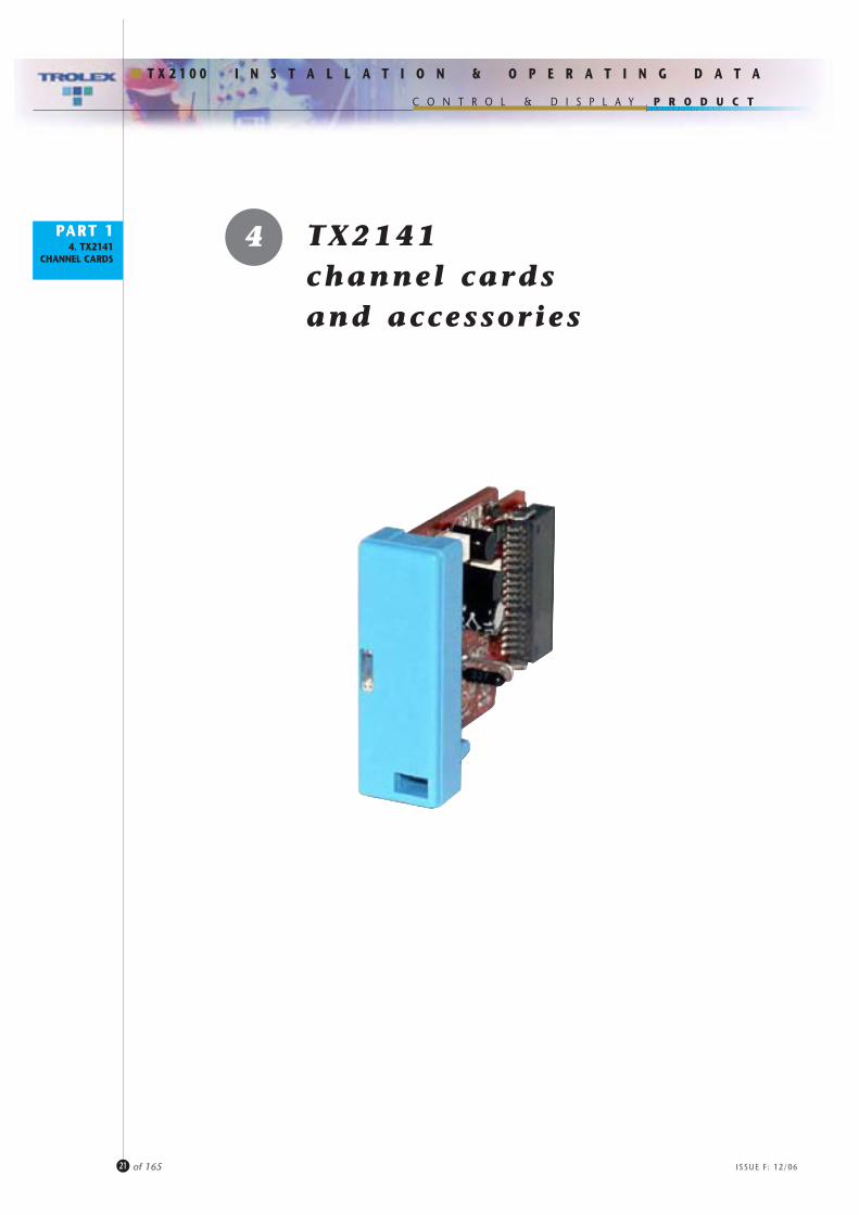
4 TX2141channel cardsand accessories
P R O D U C T
ISSUE F: 12/06
I N S T A L L A T I O N & O P E R A T I N G D A T A
C O N T R O L & D I S P L A Y
T X 2 1 0 0
PART 14. TX2141
CHANNEL CARDS
22 of 165
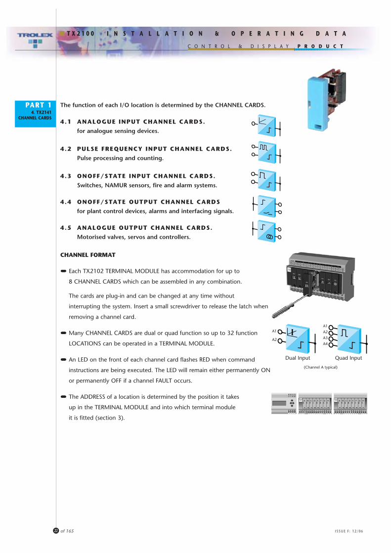
The function of each I/O location is determined by the CHANNEL CARDS.
4.1 ANALOGUE INPUT CHANNEL CARDS.
for analogue sensing devices.
4.2 PULSE FREQUENCY INPUT CHANNEL CARDS.
Pulse processing and counting.
4.3 ONOFF/STATE INPUT CHANNEL CARDS.
Switches, NAMUR sensors, fire and alarm systems.
4.4 ONOFF/STATE OUTPUT CHANNEL CARDS
for plant control devices, alarms and interfacing signals.
4.5 ANALOGUE OUTPUT CHANNEL CARDS.
Motorised valves, servos and controllers.
CHANNEL FORMAT
••••••••••••••• Each TX2102 TERMINAL MODULE has accommodation for up to
8 CHANNEL CARDS which can be assembled in any combination.
The cards are plug-in and can be changed at any time without
interrupting the system. Insert a small screwdriver to release the latch when
removing a channel card.
••••••••••••••• Many CHANNEL CARDS are dual or quad function so up to 32 function
LOCATIONS can be operated in a TERMINAL MODULE.
••••••••••••••• An LED on the front of each channel card flashes RED when command
instructions are being executed. The LED will remain either permanently ON
or permanently OFF if a channel FAULT occurs.
••••••••••••••• The ADDRESS of a location is determined by the position it takes
up in the TERMINAL MODULE and into which terminal module
it is fitted (section 3).
A B C D E F G HTØ1 A B C D E F G HTØ2
A1
A2
A1
A2
A3
A4
(Channel A typical)
Dual Input Quad Input
P R O D U C T
ISSUE F: 12/06
I N S T A L L A T I O N & O P E R A T I N G D A T A
C O N T R O L & D I S P L A Y
T X 2 1 0 0
PART 14. TX2141
CHANNEL CARDS
23 of 165
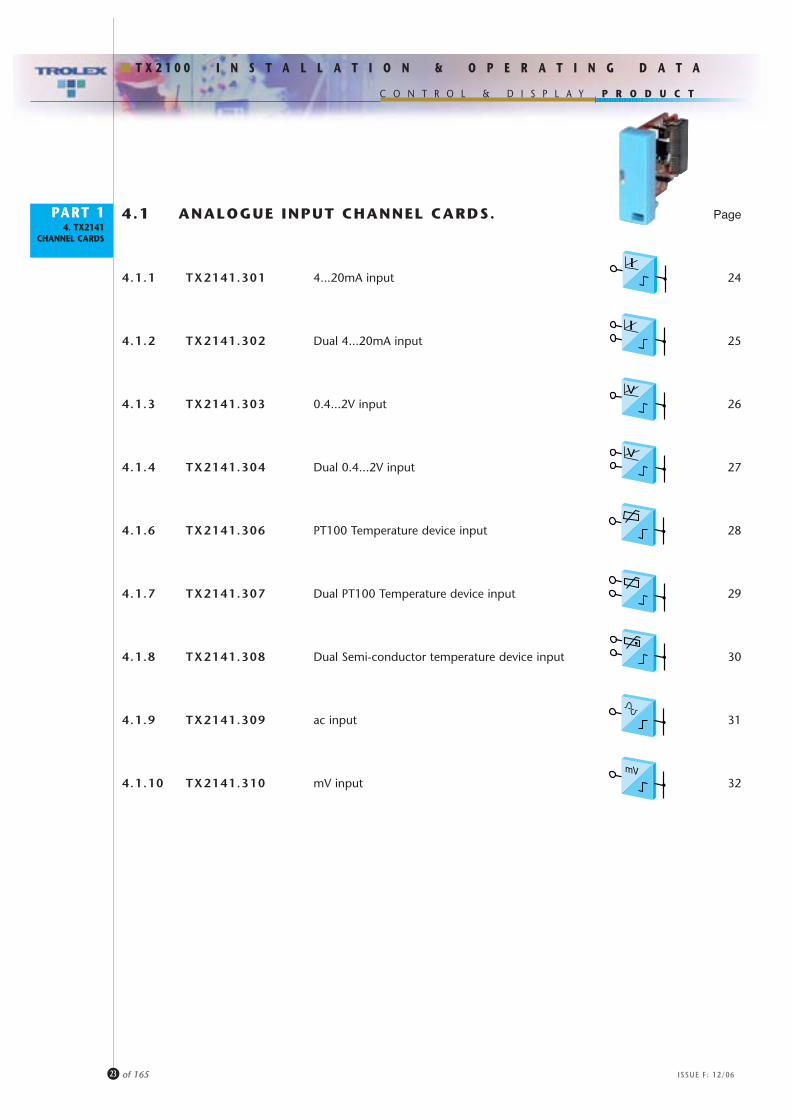
4.1 ANALOGUE INPUT CHANNEL CARDS. Page
4.1.1 TX2141.301 4...20mA input 24
4.1.2 TX2141.302 Dual 4...20mA input 25
4.1.3 TX2141.303 0.4...2V input 26
4.1.4 TX2141.304 Dual 0.4...2V input 27
4.1.6 TX2141.306 PT100 Temperature device input 28
4.1.7 TX2141.307 Dual PT100 Temperature device input 29
4.1.8 TX2141.308 Dual Semi-conductor temperature device input 30
4.1.9 TX2141.309 ac input 31
4.1.10 TX2141.310 mV input 32

P R O D U C T
ISSUE F: 12/06
I N S T A L L A T I O N & O P E R A T I N G D A T A
C O N T R O L & D I S P L A Y
T X 2 1 0 0
PART 14. TX2141
CHANNEL CARDS
24 of 165
4.1.1 TX2141.301 CHANNEL CARD
•••••••••••••••• 2, 3 or 4 wire current regulated process input signals.
•••••••••••••••• Power supply output available for sensor.
•••••••••••••••• Configurable to other current sensing ranges
i.e. 0...20mA, 0...10mA, etc. to specification.
ANALOGUE INPUT
4...20mA signal
TX2141.301.03 TX2141.301.02
Sensor Voltage: 24V dc
Channel Card Current (CI): 15mA
Maximum Cable Length:
1mm2 4000m 10000m2.5mm2 10000m 10000m
Max External Loop Resistance: 600 ohms
Recommended Cable: 2, 3 or 4 core.
Order Reference: CHANNEL CARD GENERAL PURPOSET X 2 1 4 1 . 3 0 1 . 0 3
Connections: 2 wire 3 wire 4 wire
• 2 wire signal loop• Line powered sensor
• 2 wire signal loop• Additional wire for sensor power 0V
• 2 wire signal loop• 2 wires for power +V, 0V
2a 4a
1a 3a
A1
+V
A1
2a 4a
1a 3a
+V
0V
A1
+V
2a 4a
1a 3a
0V0V
Please specify: • Specific current measuring range.
(Channel A)
Field Device Current (FI): 20mA for the signal loop. 20mA for the signal loop + additional current to power the sensor.

P R O D U C T
ISSUE F: 12/06
I N S T A L L A T I O N & O P E R A T I N G D A T A
C O N T R O L & D I S P L A Y
T X 2 1 0 0
PART 14. TX2141
CHANNEL CARDS
25 of 165
4.1.2 TX2141.302 CHANNEL CARD
•••••••••••••••• Two independent inputs.
•••••••••••••••• 2 wire current regulated process input signals.
•••••••••••••••• Line powered sensors.
•••••••••••••••• Configurable to other current sensing ranges
i.e. 0...20mA, 0...10mA, etc. to specification.
DUAL ANALOGUE INPUT
4...20mA signals
Order Reference: CHANNEL CARD GENERAL PURPOSET X 2 1 4 1 . 3 0 2 . 0 3
Connections:
2a 4a
1a 3a
A2A1+
V
+V
TX2141.302.03 TX2141.302.02
Sensor Voltage: 24V dc
Channel Card Current (CI): 15mA
Maximum Cable Length:
1mm2 4000m 10000m2.5mm2 10000m 10000m
Max External Loop Resistance: 600 ohms
Recommended Cable: 2, 3 or 4 core.
Please specify: • Specific current measuring ranges (For A1 and A2 locations).
(Channel A)
Field Device Current (FI): 20mA for each connected sensor.
P R O D U C T
ISSUE F: 12/06
I N S T A L L A T I O N & O P E R A T I N G D A T A
C O N T R O L & D I S P L A Y
T X 2 1 0 0
PART 14. TX2141
CHANNEL CARDS
26 of 165
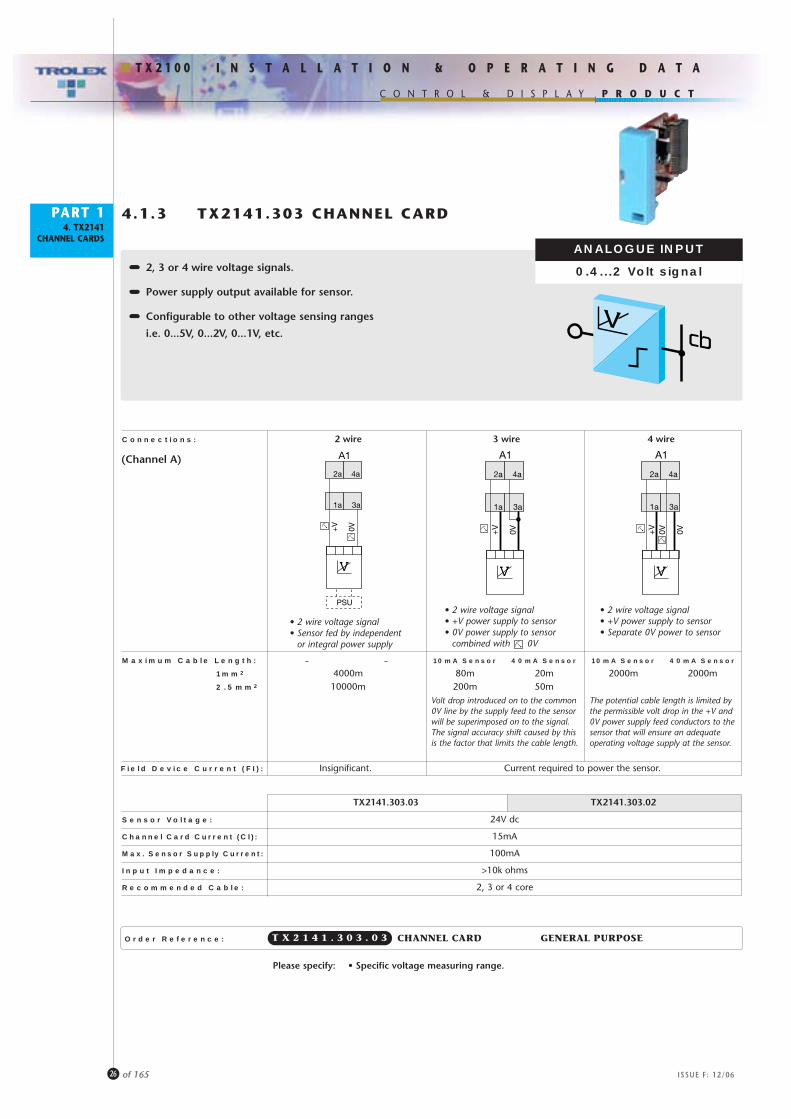
4.1.3 TX2141.303 CHANNEL CARD
•••••••••••••••• 2, 3 or 4 wire voltage signals.
•••••••••••••••• Power supply output available for sensor.
•••••••••••••••• Configurable to other voltage sensing ranges
i.e. 0...5V, 0...2V, 0...1V, etc.
ANALOGUE INPUT
0.4...2 Volt signal
Order Reference: CHANNEL CARD GENERAL PURPOSET X 2 1 4 1 . 3 0 3 . 0 3
Connections: 2 wire 3 wire 4 wire
2a 4a
1a 3a
A1
+V
0V
PSU
Maximum Cable Length: – – 10mA Sensor 40mA Sensor 10mA Sensor 40mA Sensor
1mm2 4000m 80m 20m 2000m 2000m2.5mm2 10000m 200m 50m
Volt drop introduced on to the common0V line by the supply feed to the sensorwill be superimposed on to the signal.The signal accuracy shift caused by thisis the factor that limits the cable length.
• 2 wire voltage signal• Sensor fed by independent
or integral power supply
• 2 wire voltage signal• +V power supply to sensor• 0V power supply to sensor
combined with 0V
• 2 wire voltage signal• +V power supply to sensor• Separate 0V power to sensor
The potential cable length is limited bythe permissible volt drop in the +V and0V power supply feed conductors to thesensor that will ensure an adequateoperating voltage supply at the sensor.
2a 4a
1a 3a
A1
+V
0V
2a 4a
1a 3a
A1
+V
0V 0V
Please specify: • Specific voltage measuring range.
(Channel A)
Field Device Current (FI): Insignificant. Current required to power the sensor.
TX2141.303.03 TX2141.303.02
Sensor Voltage: 24V dc
Channel Card Current (CI): 15mA
Max. Sensor Supply Current: 100mA
Input Impedance: >10k ohms
Recommended Cable: 2, 3 or 4 core

P R O D U C T
ISSUE F: 12/06
I N S T A L L A T I O N & O P E R A T I N G D A T A
C O N T R O L & D I S P L A Y
T X 2 1 0 0
PART 14. TX2141
CHANNEL CARDS
27 of 165
Maximum Cable Length: 10mA Sensor 40mA Sensor
1mm2 4000m 80m 20m2.5mm2 10000m 200m 50m
4.1.4 TX2141.304 CHANNEL CARD
•••••••••••••••• Two independent inputs.
•••••••••••••••• Power supply output available for sensors.
DUAL ANALOGUE INPUT
0.4...2 Volt signals
Order Reference: CHANNEL CARD GENERAL PURPOSET X 2 1 4 1 . 3 0 4 . 0 3
Connections: 2 wire 3 wire
• Dual 2 wire voltage signals• Sensors have independent or integral power supply
• Dual 2 wire voltage signals• +V power supply to sensors• 0V power supply to sensors combined with 0V
2a 4a
1a 3a
A2A1
0V 0V
TX2141.304.03 TX2141.304.02
Sensor Voltage: 24V dc
Channel Card Current (CI): 30mA
Max. Sensor Supply Current: 100mA
Input Impedance: >10k ohms
Recommended Cable: 2, 3 or 4 core
Isolation: Group isolated from the Commandbus.
Volt drop introduced on to the common 0V line by the supplyfeed to the sensor will be superimposed on to the signal.The signal accuracy shift caused by this is the factor thatlimits the cable length.
2a 4a
1a 3a
A2A1
+V 0V
Please specify: • Specific voltage measuring ranges (For A1 and A2 locations).
(Channel A)
Field Device Current (FI): Insignificant. Current required to power the sensor.
P R O D U C T
ISSUE F: 12/06
I N S T A L L A T I O N & O P E R A T I N G D A T A
C O N T R O L & D I S P L A Y
T X 2 1 0 0
PART 14. TX2141
CHANNEL CARDS
28 of 165
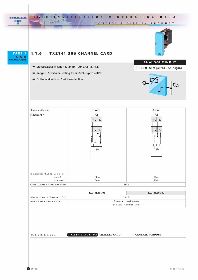
4.1.6 TX2141.306 CHANNEL CARD
•••••••••••••••• Standardised to DIN 43760, BS 1904 and IEC 751.
•••••••••••••••• Ranges: Selectable scaling from –50°C. up to 400°C.
•••••••••••••••• Optional 4 wire or 2 wire connection.
ANALOGUE INPUT
PT100 temperature signal
Order Reference: CHANNEL CARD GENERAL PURPOSET X 2 1 4 1 . 3 0 6 . 0 3
Connections:
2a 4a
1a 3a
A1
TX2141.306.03 TX2141.306.02
Channel Card Current (CI): 15mA
Recommended Cable: 2 core • overall screenor 4 core • overall screen
Maximum Cable Length:
1mm2 100m 10m2.5mm2 100m 25m
2a 4a
1a 3a
A1
2 wire4 wire
(Channel A)
Field Device Current (FI): 1mA

P R O D U C T
ISSUE F: 12/06
I N S T A L L A T I O N & O P E R A T I N G D A T A
C O N T R O L & D I S P L A Y
T X 2 1 0 0
PART 14. TX2141
CHANNEL CARDS
29 of 165
4.1.7 TX2141.307 CHANNEL CARD
•••••••••••••••• Two independent inputs.
•••••••••••••••• Standardised to DIN 43760 and BS 1904.
•••••••••••••••• Ranges: Selectable scaling from –50°C. up to 400°C.
DUAL ANALOGUE INPUT
PT100 temperature signals
Order Reference: CHANNEL CARD GENERAL PURPOSET X 2 1 4 1 . 3 0 7 . 0 3
Connections:
2a 4a
1a 3a
A1 A2
TX2141.307.03 TX2141.307.02
Channel Card Current (CI): 15mA
Maximum Cable Length:
1mm2 10m2.5mm2 25m
Recommended Cable: 2 core • overall screen per input
(Channel A)
Field Device Current (FI): 1mA per location

P R O D U C T
ISSUE F: 12/06
I N S T A L L A T I O N & O P E R A T I N G D A T A
C O N T R O L & D I S P L A Y
T X 2 1 0 0
PART 14. TX2141
CHANNEL CARDS
30 of 165
4.1.8 TX2141.308 CHANNEL CARD
•••••••••••••••• Two independent inputs.
•••••••••••••••• Linearised input.
••••••••••••••••••••• Selectable scaling from –50°C up to 200°C.
(KTY21: –50°C...100°C) (KTY84: –50°C...200°C)
DUAL ANALOGUE INPUT
semiconductor temperature signals
Order Reference: CHANNEL CARD GENERAL PURPOSET X 2 1 4 1 . 3 0 8 . 0 3
Connections:
2a 4a
1a 3a
A1 A2
TX2141.308.03 TX2141.308.02
Channel Card Current (CI): 15mA
Maximum Cable Length: 200m
Recommended Cable: 2 core
(Channel A)
Field Device Current (FI): 1mA per location
P R O D U C T
ISSUE F: 12/06
I N S T A L L A T I O N & O P E R A T I N G D A T A
C O N T R O L & D I S P L A Y
T X 2 1 0 0
PART 14. TX2141
CHANNEL CARDS
31 of 165
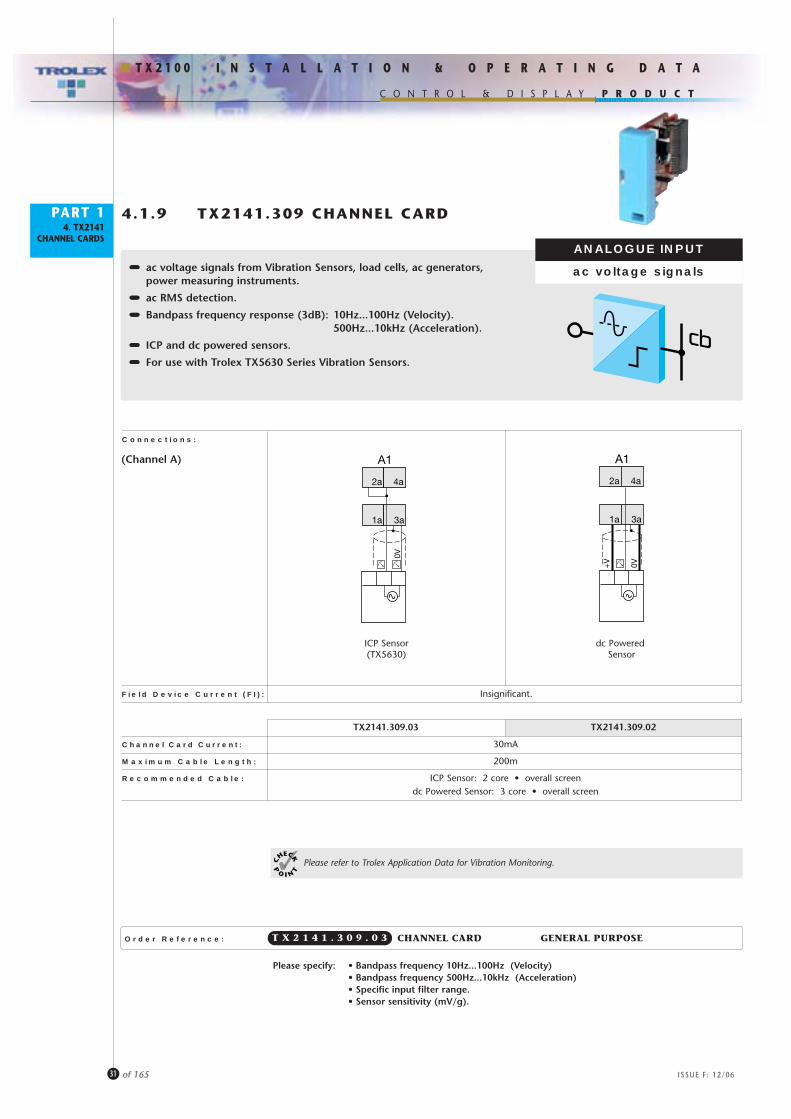
4.1.9 TX2141.309 CHANNEL CARD
•••••••••••••••• ac voltage signals from Vibration Sensors, load cells, ac generators,power measuring instruments.
•••••••••••••••• ac RMS detection.
•••••••••••••••• Bandpass frequency response (3dB): 10Hz...100Hz (Velocity).500Hz...10kHz (Acceleration).
•••••••••••••••• ICP and dc powered sensors.
•••••••••••••••• For use with Trolex TX5630 Series Vibration Sensors.
ANALOGUE INPUT
ac voltage signals
Order Reference: CHANNEL CARD GENERAL PURPOSET X 2 1 4 1 . 3 0 9 . 0 3
Connections:
Please specify: • Bandpass frequency 10Hz...100Hz (Velocity)• Bandpass frequency 500Hz...10kHz (Acceleration)• Specific input filter range.• Sensor sensitivity (mV/g).
2a 4a
1a 3a
A1
0V
TX2141.309.03 TX2141.309.02
Channel Card Current: 30mA
Maximum Cable Length: 200m
Recommended Cable: ICP Sensor: 2 core • overall screendc Powered Sensor: 3 core • overall screen
Please refer to Trolex Application Data for Vibration Monitoring.
2a 4a
1a
0V+V
3a
A1
ICP Sensor(TX5630)
dc PoweredSensor
(Channel A)
Field Device Current (FI): Insignificant.

P R O D U C T
ISSUE F: 12/06
I N S T A L L A T I O N & O P E R A T I N G D A T A
C O N T R O L & D I S P L A Y
T X 2 1 0 0
PART 14. TX2141
CHANNEL CARDS
32 of 165
4.1.10 TX2141.310 CHANNEL CARD
•••••••••••••••• Low level inputs from balanced bridges, load cells, strain gauges,pressure sensors and gas sensors.
•••••••••••••••• Measuring range options.
•••••••••••••••• Current regulated sensor energising supply output.
•••••••••••••••• Zero offset and span calibration.
•••••••••••••••• Accepts input signals from TX6250 series Infra-Red Temperature Sensors.Application specific ranges from –20°C up to 400°C.
ANALOGUE INPUT
mV signals
Order Reference: CHANNEL CARD GENERAL PURPOSET X 2 1 4 1 . 3 1 0 . 0 3
Connections:
2a 4a
1a
+V
0V+V
0V
3a
A1
Balanced Bridge
TX6250 seriesInfra Red
Temperature Sensor
2a 4a
1a
+V
0V
3a
A1
TX2141.310.03 TX2141.310.02
Channel Card Current (CI): 15mA
Measuring Ranges: 0...2mV / 0...5mV / 0...10mV / 0...50mV / 0...100mV / 0...1000mV / 0...2000mV
Sensor Current Regulation: 0...50mA
Input Impedance: 100k ohms
Max Sensor Supply Current: 100mA
Maximum Cable Length: 200m
Recommended Cable: 4 core • overall screen
Please specify: • Measuring range 0...2mV• Measuring range 0...5mV• Measuring range 0...10mV• Measuring range 0...50mV• Measuring range 0...100mV
• Measuring range 0...1V• Measuring range 0...2V• Measuring range Specific Voltage
(Channel A)
Field Device Current (FI): Current required to power the sensor.

P R O D U C T
ISSUE F: 12/06
I N S T A L L A T I O N & O P E R A T I N G D A T A
C O N T R O L & D I S P L A Y
T X 2 1 0 0
PART 14. TX2141
CHANNEL CARDS
33 of 165
4.2 PULSE FREQUENCY INPUT CHANNEL CARD.
4.2.1 TX2141.401 Pulse/frequency input

P R O D U C T
ISSUE F: 12/06
I N S T A L L A T I O N & O P E R A T I N G D A T A
C O N T R O L & D I S P L A Y
T X 2 1 0 0
PART 14. TX2141
CHANNEL CARDS
34 of 165
4.2.1 TX2141.401 CHANNEL CARD
•••••••••••••••• Pulse frequency signals from switches, proximity sensors,photocells and pulse wheels, frequency generators.
•••••••••••••••• Two independent inputs for function options.
•••••••••••••••• Frequency range: 0...10kHz.
•••••••••••••••• Programmable for: counting, pulse interval, pulse frequency, differentialfrequency, percentage pulse comparison, slip frequency, differential slip.
DIGITAL INPUT
pulse/frequency signals
Order Reference: CHANNEL CARD GENERAL PURPOSET X 2 1 4 1 . 4 0 1 . 0 3
Connections:
• Input switches(section 12.2.2 ).
• NAMUR proximity sensorsDIN 19234
• Discrete fault alarm generated for OPEN CIRCUIT and SHORT CIRCUIT line condition.(section 12.2.2 ).
• Solid state or photocell input(section 12.2.2 ).
TX2141.401.03 TX2141.401.02
Channel Card Current (CI): 30mA
Maximum Cable Length: 500m
Recommended Cable: 2 core • overall screen (per input)
Sensor Voltage: 8.2V
Frequency Range: 0...10kHz
2a 4a
1a 3a
A1
P1 P2
+V
+V
P1 P2
2a 4a
1a 3a
A1
+V
+V
P1 P2
2a 4a
1a 3a
A1
+V
+V+V
0V
Present
Absent
Input Signal
(Channel A)
Field Device Current (FI): Insignificant 2mA per NAMUR Insignificant

P R O D U C T
ISSUE F: 12/06
I N S T A L L A T I O N & O P E R A T I N G D A T A
C O N T R O L & D I S P L A Y
T X 2 1 0 0
PART 14. TX2141
CHANNEL CARDS
35 of 165
4.3 ONOFF/STATE INPUT CHANNEL CARD.
4.3.1 TX2141.501 Dual NAMUR inputs
4.3.2 TX2141.502 Dual Switch inputs with line monitoring
4.3.3 TX2141.503 Dual Current state change inputs
4.3.4 TX2141.504 Quad Switch inputs

P R O D U C T
ISSUE F: 12/06
I N S T A L L A T I O N & O P E R A T I N G D A T A
C O N T R O L & D I S P L A Y
T X 2 1 0 0
PART 14. TX2141
CHANNEL CARDS
36 of 165
4.3.1 TX2141.501 CHANNEL CARD
•••••••••••••••• Change of state signals.
•••••••••••••••• Two independent inputs for NAMUR sensor inputs.
•••••••••••••••• Two independent inputs for simple ON/OFF switches.
DUAL DIGITAL INPUT
NAMUR inputs
Order Reference: CHANNEL CARD GENERAL PURPOSET X 2 1 4 1 . 5 0 1 . 0 3
Connections:
• 2 x NAMUR proximity sensors to DIN 19234.
• Discrete FAULT alarm generated for OPEN CIRCUIT and SHORT CIRCUIT line condition (section 12.2.3 ).
TX2141.501.03 TX2141.501.02
Channel Card Current (CI): 30mA
Maximum Cable Length: 500m
Recommended Cable: 2 core • overall screen (per input)
Supply Voltage: 8.2V
Max Switch Frequency: 10Hz
2a 4a
1a 3a
A1 A2
+V
+V
2a 4a
1a 3a
A1 A2
+V
+V
• Can also be used with 2 x conventional ON/OFF switches. (section 12.2.3 ).
+V
0V
Present
Absent
Input Signal
(Channel A)
Field Device Current (FI): 2mA max per NAMUR

P R O D U C T
ISSUE F: 12/06
I N S T A L L A T I O N & O P E R A T I N G D A T A
C O N T R O L & D I S P L A Y
T X 2 1 0 0
PART 14. TX2141
CHANNEL CARDS
37 of 165
4.3.2 TX2141.502 CHANNEL CARD
•••••••••••••••• Change of state signals.
•••••••••••••••• Two independent inputs for simple ON/OFF switches
with sensor line monitoring.
DUAL DIGITAL INPUT
Switch inputs with line monitoring
Order Reference: CHANNEL CARD GENERAL PURPOSET X 2 1 4 1 . 5 0 2 . 0 3
Connections:
• Switches with series diode• Detection of SHORT CIRCUIT switch line, with series diode• Detection of OPEN CIRCUIT switch line also, when contact
shunt resistor is added• Discrete FAULT alarms generated for OPEN CIRCUIT and
SHORT CIRCUIT line condition (section 12.2.3 )
TX2141.502.03 TX2141.502.02
Channel Card Current (CI): 15mA
Maximum Cable Length: 500m
Recommended Cable: 2 core • overall screen (per input)
A1 A2
2a 4a
1a 3a
+V
+V
+V
0V
Present
Absent
Input Signal
(Channel A)
Field Device Current (FI): 1mA per location

P R O D U C T
ISSUE F: 12/06
I N S T A L L A T I O N & O P E R A T I N G D A T A
C O N T R O L & D I S P L A Y
T X 2 1 0 0
PART 14. TX2141
CHANNEL CARDS
38 of 165
4.3.3 TX2141.503 CHANNEL CARD
•••••••••••••••• Change of state signals.
•••••••••••••••• Two independent inputs for sensors with current
STATE CHANGE for fire and gas applications, smoke, flame,
breakglass, etc.
DUAL DIGITAL INPUT
Current state inputs
Order Reference: CHANNEL CARD GENERAL PURPOSET X 2 1 4 1 . 5 0 3 . 0 3
Connections:
• Discrete FAULT alarms generated for OPEN CIRCUIT or SHORT CIRCUIT condition (section 12.2.3 )
• Current level state change. Normal: Less than 8mAAlarm: More than 20mA
• Maximum number of loop devices: 25
TX2141.503.03 TX2141.503.02
Channel Card Current (CI): 30mA
Maximum Cable Length: 500m
Recommended Cable: 2 core • overall screen (per input)
A1 A2
2a 4a
1a 3a
+V
0V
Present
Absent
Input Signal
(Channel A)
Field Device Current (FI): Insignificant.

P R O D U C T
ISSUE F: 12/06
I N S T A L L A T I O N & O P E R A T I N G D A T A
C O N T R O L & D I S P L A Y
T X 2 1 0 0
PART 14. TX2141
CHANNEL CARDS
39 of 165
4.3.4 TX2141.504 CHANNEL CARD
•••••••••••••••• Change of state signals.
•••••••••••••••• Four independent inputs for simple ON/OFF switches.
•••••••••••••••• Limit switches, pressure switches, level switches, etc.
QUAD DIGITAL INPUT
Switch inputs
Order Reference: CHANNEL CARD GENERAL PURPOSET X 2 1 4 1 . 5 0 4 . 0 3
Connections:
TX2141.504.03
Channel Card Current (CI): 15mA
Maximum Cable Length: 500m
Recommended Cable: 2 core
Max Switch Input Voltage: 30V dc.• May be sourced from a separate power supply.
• The 0V of both systems must be common.
Max Switch Frequency: 10Hz
A1 A3A2 A4
2a 4a
1a
+V
3a
+V
0V
Present
Absent
Input Signal
(Channel A)
Field Device Current (FI): Insignificant.

P R O D U C T
ISSUE F: 12/06
I N S T A L L A T I O N & O P E R A T I N G D A T A
C O N T R O L & D I S P L A Y
T X 2 1 0 0
PART 14. TX2141
CHANNEL CARDS
40 of 165
4.4 ONOFF/STATE OUTPUT CHANNEL CARDS.
4.4.3 TX2141.603 Quad Solid State Output
4.4.4 TX2141.604 Dual Relay Output
P R O D U C T
ISSUE F: 12/06
I N S T A L L A T I O N & O P E R A T I N G D A T A
C O N T R O L & D I S P L A Y
T X 2 1 0 0
PART 14. TX2141
CHANNEL CARDS
41 of 165
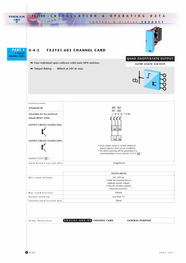
4.4.3 TX2141.603 CHANNEL CARD
•••••••••••••••• Four individual open collector solid state NPN switches.
•••••••••••••••• Output Rating: 400mA at 24V dc max.
QUAD ONOFF/STATE OUTPUT
solid state switch
Order Reference: CHANNEL CARD GENERAL PURPOSET X 2 1 4 1 . 6 0 3 . 0 3
Connections:
TX2141.603.03
Max Load Voltage: 10...25V dc• May be sourced from aseparate power supply.
• The 0V of both systemsmust be common.
Max Load Current: 100mA.
Output Voltdrop: Less than 1V.
Channel Card Current (CI): 30mA
2a 4a
0V
1a 3a
A1 A3A2 A4
• Each output circuit is current limited to protect against short circuit conditions.
• An alarm warning will be generated if a switching failure occurs (section 12.2.4 )
(Channel A)
Field Device Current (FI): Insignificant.
Selectable for the preferred
failsafe RESET STATE:
OUTPUT CIRCUIT CLOSED (ON)
OUTPUT CIRCUIT CLOSED (OFF)
(section 12.2.4 )

P R O D U C T
ISSUE F: 12/06
I N S T A L L A T I O N & O P E R A T I N G D A T A
C O N T R O L & D I S P L A Y
T X 2 1 0 0
PART 14. TX2141
CHANNEL CARDS
42 of 165
4.4.4 TX2141.604 CHANNEL CARD
•••••••••••••••• Two individual medium duty relays.
•••••••••••••••• Voltage free output contacts.
•••••••••••••••• Contact Rating: 2A 30V ac/dc.
•••••••••••••••• Contact Format: 1 N/O on each relay.
•••••••••••••••• Galvanically isolated output from the Commandbus.
DUAL ONOFF/STATE OUTPUT
relay
Order Reference: CHANNEL CARD GENERAL PURPOSET X 2 1 4 1 . 6 0 4 . 0 3
Connections:
• Relay shown de-energised – no power• FAULT alarm generated if a relay operation
failure is detected (12.2.4 )
TX2141.604
Max Contact Voltage: 30V ac/dc
Max Contact Current: 2A (resistive load)
Contact Format: 1 normally open
Channel Card Current (CI): 30mA
Isolation: Output contacts are galvanically isolated
2a 4a
1a 3a
A1 A2(Channel A)
Field Device Current (FI): Insignificant.
Programmable in the SETUP
section for the preferred failsafe
RESET STATE:
(section 12.2.4 )
OUTPUT CIRCUIT CLOSED (ON)
OUTPUT CIRCUIT CLOSED (OFF)
Standard contacts are wiredNORMALLY OPEN
NB: Contacts can also be supplied wired as NORMALLY CLOSED to specification.

P R O D U C T
ISSUE F: 12/06
I N S T A L L A T I O N & O P E R A T I N G D A T A
C O N T R O L & D I S P L A Y
T X 2 1 0 0
PART 14. TX2141
CHANNEL CARDS
43 of 165
4.5 ANALOGUE OUTPUT CHANNEL CARD.
4.5.1 TX2141.701 Dual 4...20mA Output

• Must only be interconnected with approved field apparatus when used in hazardous area applications.
TX2141.701.03 TX2141.701.02
Channel Card Current (CI): 15mA
Output Signal: 4...20mA
Maximum Load: 450 ohms
P R O D U C T
ISSUE F: 12/06
I N S T A L L A T I O N & O P E R A T I N G D A T A
C O N T R O L & D I S P L A Y
T X 2 1 0 0
PART 14. TX2141
CHANNEL CARDS
44 of 165
4.5.1 TX2141.701 CHANNEL CARD
•••••••••••••••• Two independent outputs.
•••••••••••••••• Output control for motorised valves, controllers, servo devices, process loops, inverters, recorders, speed controllers, heat controllers.
•••••••••••••••• 4...20mA repeater when driven from an analogue channel card.
•••••••••••••••• Can be data code driven when a specific program is installedin the Command module (LAN 1/LAN 2).
DUAL ANALOGUE OUTPUT
4...20mA
Connections:
Order Reference: CHANNEL CARD GENERAL PURPOSET X 2 1 4 1 . 7 0 1 . 0 3
2a 4a
1a 3a
+V
+V
A1 A2
• UNDER RANGE/OVER RANGE will be indicated (section 10.2).• LOW FAULT/HIGH FAULT will be indicated (section 10.2 and section 12.2.4 )
(Channel A)
Field Device Current (FI): 20mA for each field device connected.
P R O D U C T
ISSUE F: 12/06
I N S T A L L A T I O N & O P E R A T I N G D A T A
C O N T R O L & D I S P L A Y
T X 2 1 0 0
PART 14. TX2141
CHANNEL CARDS
45 of 165
4.6 ACCESSORIES.
TX2141.08 Blank Channel Card to cover unused locations.
TX2141.09 Marking tag bar
Self-adhesive fixing to the
TX2102 Terminal Module.
Supplied complete with 8 white tags
for marking the specific duty reference
of each channel.
4.7 COMMANDER CONNECTING TERMINALS.
Commander modules are fitted with large size, high integrity screw terminals, housing captive
spring clamping washers for ease of access, and security of connection even in conditions
where vibration in present.
• Direct Connection
Two 2.5mm2 conductors side by side.
• Crimp Connection
Two Bootlace crimps side by side
or single Fork crimps: 6.5mm wide.
• Screwdriver
4mm Flatblade or size 1 Pozidrive.

P R O D U C T
ISSUE F: 12/06
I N S T A L L A T I O N & O P E R A T I N G D A T A
C O N T R O L & D I S P L A Y
T X 2 1 0 0
PART 14. TX2141
CHANNEL CARDS
46 of 165
4.8 HOUSINGS FOR COMMANDER SYSTEMS.
TX9200 Series stainless steel Commander housings.
• Robust welded stainless steel construction.
• Mounting rails fitted.
• Observation window.
• Hinged cover with lockable fastening.
• Wall fixing facilities.
• IP66 environmental protection.
Moulded Polycarbonate weatherproof housings in a range of sizes.
• Transparent waterproof hinged covers.
• Wall fixing kit.
• Mounting rails fitted.
• Masking plates provided.
• Choice of cable entry facilities.
300.
0
100.0
Entry holes Ø22.0for M20 cable glands
TX9204TX9202
400.020.0
20.0
200.0
Stand-aloneWall Mounting
CommandModule.
Terminal Modulewith Commandbus
ConvertorCompilation Commander Station
• Command Module• Comms Repeater• Terminal Module• Commandbus Convertor

P R O D U C T
ISSUE F: 12/06
I N S T A L L A T I O N & O P E R A T I N G D A T A
C O N T R O L & D I S P L A Y
T X 2 1 0 0
PART 15. TX2131
COMMANDBUSCONVERTOR
MODULES
47 of 165
5 TX2131commandbusconvertor module
TX2121commandbusrepeater module
48 of 165
P R O D U C T
ISSUE F: 12/06
I N S T A L L A T I O N & O P E R A T I N G D A T A
C O N T R O L & D I S P L A Y
T X 2 1 0 0
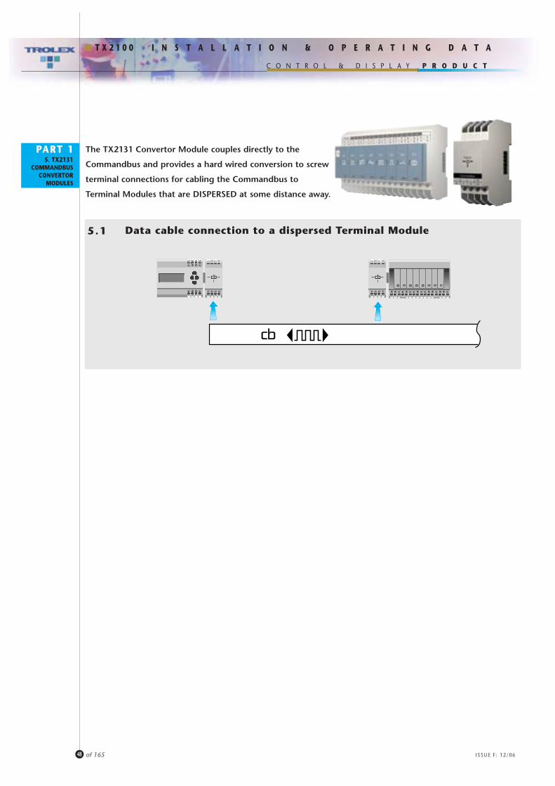
The TX2131 Convertor Module couples directly to the
Commandbus and provides a hard wired conversion to screw
terminal connections for cabling the Commandbus to
Terminal Modules that are DISPERSED at some distance away.
Data cable connection to a dispersed Terminal Module5.1
PART 15. TX2131
COMMANDBUSCONVERTOR
MODULES

P R O D U C T
ISSUE F: 12/06
I N S T A L L A T I O N & O P E R A T I N G D A T A
C O N T R O L & D I S P L A Y
T X 2 1 0 0
PART 1
49 of 165
Locally dispersed Commander system communicating data to andfrom a central Command Module
5.25. TX2131
COMMANDBUSCONVERTOR
MODULES
Power supply considerations (section 5.4)
• Total line length (without repeaters) can be up to 1000m dependent upon application condition,or a maximum of
30 Terminal Modules.

50 of 165
P R O D U C T
ISSUE F: 12/06
I N S T A L L A T I O N & O P E R A T I N G D A T A
C O N T R O L & D I S P L A Y
T X 2 1 0 0
I/O signals and data entering at one end of the system are directly replicated as I/O at the other end, using
a single data cable.
5.3 A Commander System programmed to function inComplementary Mode.
SENSOR INPUTS
CONTROL OUTPUTS
SENSOR INPUTS
CONTROL OUTPUTS
A Commander system in complementary mode exchanging data and control signals along a tunnel.
The transmission distance of the Commandbus may be increased at any point by using a TX2121
comms repeater module (section 5).
PART 15. TX2131
COMMANDBUSCONVERTOR
MODULES

51 of 165
P R O D U C T
ISSUE F: 12/06
I N S T A L L A T I O N & O P E R A T I N G D A T A
C O N T R O L & D I S P L A Y
T X 2 1 0 0
The dc power supply to energise a Commander System is normally an integral part of the Commandbus.
• Both data and power can be transmitted to dispersed Commander Stations.
• Recommended cable (with power): 2 twisted pairs • Individually screened pairs, Collectively screened •BS 5308 pt1.
• The screen of the Commandbus is ultimately internally connected to the 0V terminal on the Command Module ONLY.Connect the Command Module 0V to a secure Earth at this point ONLY if required.
If independent power supplies are installed at EACH dispersed Commander station it means that the Commandbus
cable can be reduced to 2 cores (1 twisted pair), as the +V and 0V power conductors are now eliminated. This fact
can also, potentially, increase the transmitting distance because the supply voltage delivered to the Commander
modules will be no longer influenced by volt drop in the run of interconnecting cable.
Larger scale systems can also be assembled now that the total power supply capability is not limited by the current
capacity of the power supply at the Commander base station.
5.4 Power Supply distribution to dispersed Commander Stations.
Commander TerminalModule
TerminalModule
ConvertorModule
ConvertorModule
dat
a
pow
er
dat
a
pow
er
PowerSupply
ABSc Screen 0V+V
DATA
POWER
PART 15. TX2131
COMMANDBUSCONVERTOR
MODULES
CommanderTX2101.03 TX2102.03 TX2131.03 TX2171 TX2131.03 TX2102.03 TX2171
TerminalModule
TerminalModule
ConvertorModule
ConvertorModule
PowerSupply
PowerSupply
dat
a
dat
a
only
only
Data only
52 of 165
P R O D U C T
ISSUE F: 12/06
I N S T A L L A T I O N & O P E R A T I N G D A T A
C O N T R O L & D I S P L A Y
T X 2 1 0 0
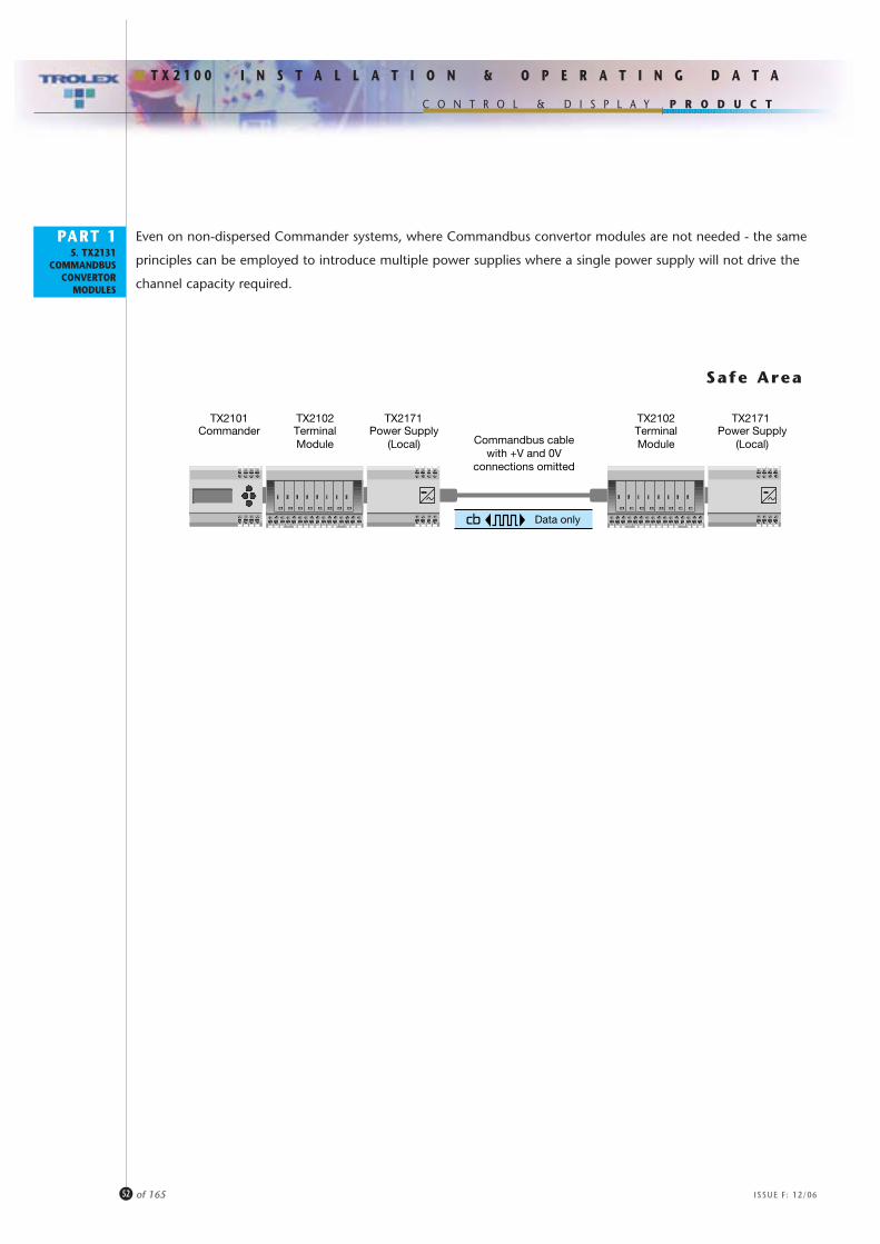
Even on non-dispersed Commander systems, where Commandbus convertor modules are not needed - the same
principles can be employed to introduce multiple power supplies where a single power supply will not drive the
channel capacity required.
CommanderTX2101 TX2102 TX2171 TX2102 TX2171
TerminalModule
TerminalModule
Power Supply(Local)
Power Supply(Local)Commandbus cable
with +V and 0Vconnections omitted
Data only
PART 15. TX2131
COMMANDBUSCONVERTOR
MODULES
Safe Area
53 of 165
P R O D U C T
ISSUE F: 12/06
I N S T A L L A T I O N & O P E R A T I N G D A T A
C O N T R O L & D I S P L A Y
T X 2 1 0 0
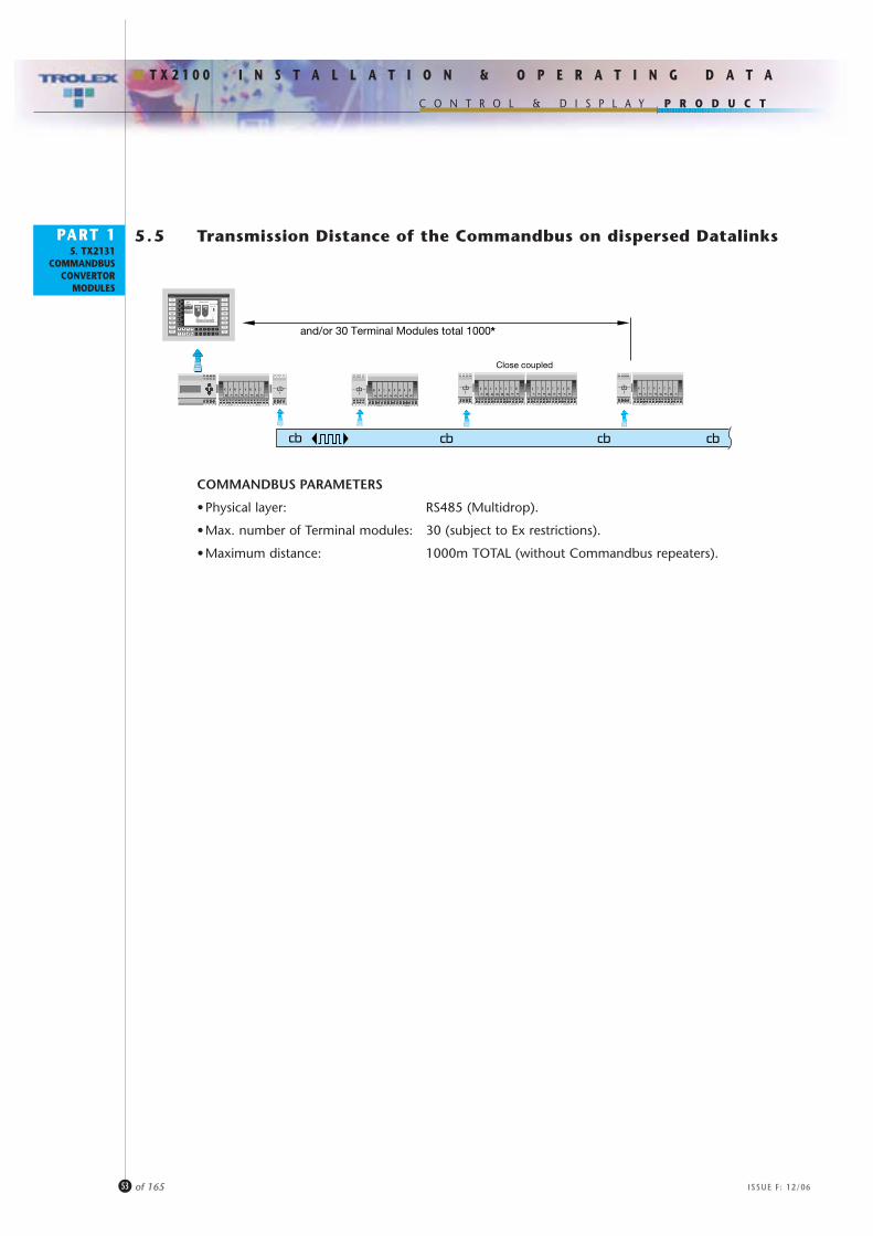
5.5 Transmission Distance of the Commandbus on dispersed DatalinksPART 15. TX2131
COMMANDBUSCONVERTOR
MODULES
and/or 30 Terminal Modules total 1000*
Close coupled
COMMANDBUS PARAMETERS
•Physical layer: RS485 (Multidrop).
•Max. number of Terminal modules: 30 (subject to Ex restrictions).
•Maximum distance: 1000m TOTAL (without Commandbus repeaters).
P R O D U C T
ISSUE F: 12/06
I N S T A L L A T I O N & O P E R A T I N G D A T A
C O N T R O L & D I S P L A Y
T X 2 1 0 0
54 of 165
PART 15. TX2131
COMMANDBUSCONVERTOR
MODULES
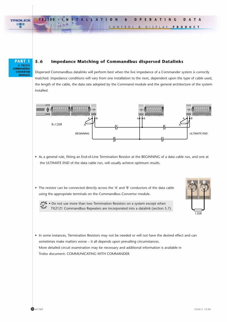
5 .6 Impedance Matching of Commandbus dispersed Datalinks
Dispersed Commandbus datalinks will perform best when the live impedance of a Commander system is correctly
matched. Impedance conditions will vary from one installation to the next, dependent upon the type of cable used,
the length of the cable, the data rate adopted by the Command module and the general architecture of the system
installed.
• As a general rule, fitting an End-of-Line Termination Resistor at the BEGINNING of a data cable run, and one at
the ULTIMATE END of the data cable run, will usually achieve optimum results.
• The resistor can be connected directly across the 'A' and 'B' conductors of the data cable
using the appropriate terminals on the Commandbus Convertor module.
• In some instances, Termination Resistors may not be needed or will not have the desired effect and can
sometimes make matters worse – it all depends upon prevailing circumstances.
More detailed circuit examination may be necessary and additional information is available in
Trolex document: COMMUNICATING WITH COMMANDER.
A B A BA B
R R
BEGINNING ULTIMATE END
R=120R
A B
120R
• Do not use more than two Termination Resistors on a system except when TX2121 Commandbus Repeaters are incorporated into a datalink (section 5.7).

P R O D U C T
ISSUE F: 12/06
I N S T A L L A T I O N & O P E R A T I N G D A T A
C O N T R O L & D I S P L A Y
T X 2 1 0 0
55 of 165
PART 15. TX2131
COMMANDBUSCONVERTOR
MODULES
5 .7 Using a TX2121 Commandbus Repeater
In most applications where a TX2121 Commandbus Repeater is incorporated into a dispersed Commandbus, it will
be necessary to connect Termination Resistors to BOTH ports of the Repeater in addition to the ones at the
BEGINNING and ULTIMATE END of the datalink.
Here again, this may need further expert analysis where unusual conditions prevail.
A1
TX2121Commandbus
Repeater
A2
B1 B2
R R

56 of 165
P R O D U C T
ISSUE F: 12/06
I N S T A L L A T I O N & O P E R A T I N G D A T A
C O N T R O L & D I S P L A Y
T X 2 1 0 0
Order Reference: COMMANDBUS CONVERTOR MODULE
Connections:
Recommended Cable (with power): 2 twisted pair • Individually Screened • Collectively Screened • B5308 pt1
Recommended Cable (no power): 1 twisted pair • Collectively Screened • B5308 pt1
Maximum Power Supply Current: 6 Amps (system total).
Dimensions:
5.6 TX2131 COMMANDBUS CONVERTOR MODULE
•••••••••••••••• Converts the Commandbus to screw terminal connections to enable
cable connection runs to locally dispersed Commander systems.
•••••••••••••••• Internally hard-wired passive device.
T X 2 1 3 1
All dimensions in mm.
M F Sc
A B +V 0V
ABSc 0V+V
AB
Sc
0V+V
Commandbusconnection
for close couplingto the FEMALE
port of aTerminal Module.
F/M F/M
Commandbusconnectionfor close couplingto the MALEport of aTerminal Module.
3658
AlternativeFixing Holesø4mm
99 90
90 C
TRS
DIN RailMounting
PART 15. TX2131
COMMANDBUSCONVERTOR
MODULES
• The screen of the Commandbus is ultimately internally connected to the 0V terminal on the Command Module ONLY.Connect the Command Module 0V to a secureEarth at this point ONLY if required.
• The Commandbus Convertor MUST only beconnected to one port (M or F).Do not use it as a ‘branch’ connection.
57 of 165
P R O D U C T
ISSUE F: 12/06
I N S T A L L A T I O N & O P E R A T I N G D A T A
C O N T R O L & D I S P L A Y
T X 2 1 0 0
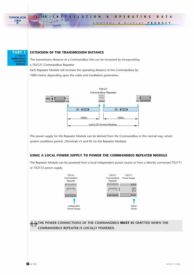
EXTENSION OF THE TRANSMISSION DISTANCE
The transmission distance of a Commandbus link can be increased by incorporating
a TX2121 Commandbus Repeater.
Each Repeater Module will increase the operating distance of the Commandbus by
1000 metres depending upon the cable and installation parameters.
PART 15. TX2131
COMMANDBUSCONVERTOR
MODULES
1000m
TX2121Commandbus Repeater
1000m
and/or 30 Terminal Modules
The power supply for the Repeater Module can be derived from the Commandbus in the normal way, where
system conditions permit. (Terminals +V and 0V on the Repeater Module).
USING A LOCAL POWER SUPPLY TO POWER THE COMMANDBUS REPEATER MODULE
The Repeater Module can be powered from a local independent power source or from a directly connected TX2171
or TX2172 power supply.
THE POWER CONNECTIONS OF THE COMMANDBUS MUST BE OMITTED WHEN THE
COMMANDBUS REPEATER IS LOCALLY POWERED.
TX2171Power Supply
TX2121Commandbus
Repeater
TX2121Commandbus
Repeater
MainsPower
IndependentPower Supply

P R O D U C T
ISSUE F: 12/06
I N S T A L L A T I O N & O P E R A T I N G D A T A
C O N T R O L & D I S P L A Y
T X 2 1 0 0
PART 15. TX2121
COMMANDBUSREPEATERMODULES
58 of 165
Power Supply: •24V on terminals +V and 0V(Can be derived from the Commandbus cable where operating conditions permit).
•Power can also be supplied locally from an approved 24V dc supply connected to terminals +V and 0V.THE POWER CONNECTIONS OF THE COMMANDBUS MUST BE OMITTED.
•Power can also be supplied locally from a directly connected TX2171 24V dc power supply through the bus power connection.THE POWER CONNECTIONS OF THE COMMANDBUS MUST BE OMITTED.
Current Consumption: 30mA
Physical Layer: RS485.
Protocol: Trolex proprietary.
Additional 1000m (Dependent upon cable and installation parameters).
Distance:
Recommended Cable: Twisted pair • Collectively Screened • B5308 pt1
Dimensions:
Connections:
•••••••••••••••• Commandbus repeater with galvanic isolation.
•••••••••••••••• Increase distance on Commandbus networks.
All dimensions in mm.
TX2121.03 COMMANDBUS REPEATER MODULE
GENERAL PURPOSE
isolated datacomms
Order Reference: COMMANDBUS REPEATER MODULE. GENERAL PURPOSET X 2 1 2 1 . 0 3
7258
AlternativeFixing Holesø4mm
99 90
90 C
TRS
DIN RailMounting
FScSc
0V+V
Bus connection forpower only when closecoupled to aTX2171 Power Supply.
The data ports are bipolar and data flow can be either direction
0V+VA1 B1 0V+VA2 B2
The module must be mounted in a protective metal housing (eg: TX9202 or TX9204).
• The screen of the Commandbus is ultimately internally connected to the 0V terminal on the Command Module ONLY.Connect the Command Module 0V to a secureEarth at this point ONLY if required.

P R O D U C T
ISSUE F: 12/06
I N S T A L L A T I O N & O P E R A T I N G D A T A
C O N T R O L & D I S P L A Y
T X 2 1 0 0
PART 15. TX2121
COMMANDBUSREPEATERMODULES
59 of 165
Commandbus System Capacity
• Maximum TERMINAL MODULES : 30
• Maximum CHANNEL CARDS : 30 x 8 = 240
• Maximum LOCATIONS : 240 x Single = 240
240 x Dual = 480
240 x Quad = 960
Maximum Cable Distance : 1000m total line length without Commandbus repeaters
(dependent upon installation parameters)
A TX2121Commandbus Repeater will give a further
1000m distance.
} (or any combination of these)
Commandbus Response Time
Response time of a given Commander system configuration is a function of the number of Terminal
Modules in the network.
Response Time = TERMINAL MODULES x 100 milliseconds
System ArchitectureIn practice, the structural architecture and operating distribution of a Commander system are both influenced by related technical parameters:
• The topology and distribution of the plant.• The type of sensors and plant devices.• System power requirements and power distribution.• The type of cable used for the databus.• The overall resultant time response of the system.
Our Commander system application engineers can provide technical assessment of individual installation designs.
COMMANDER SYSTEM DESIGN
• Power supply considerations (section 5.4).
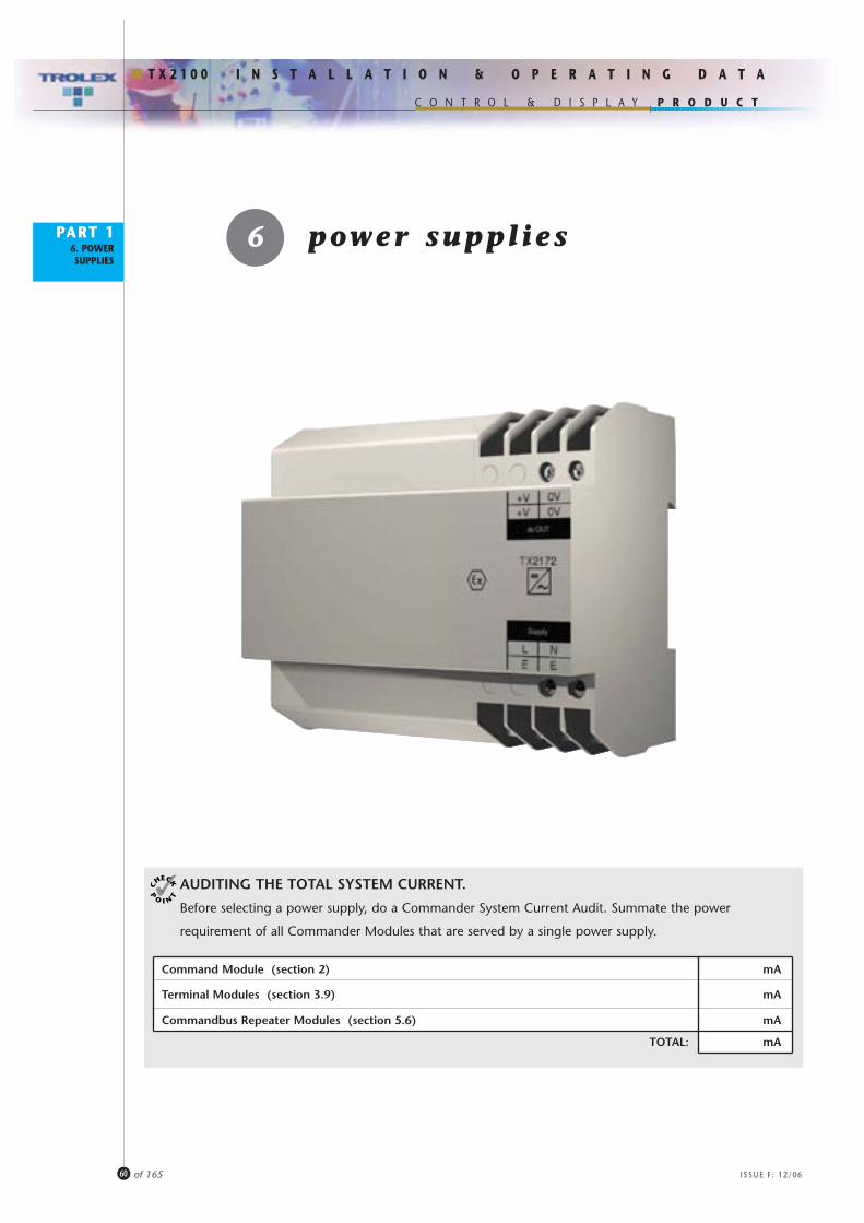
AUDITING THE TOTAL SYSTEM CURRENT.
Before selecting a power supply, do a Commander System Current Audit. Summate the power
requirement of all Commander Modules that are served by a single power supply.
P R O D U C T
ISSUE F: 12/06
I N S T A L L A T I O N & O P E R A T I N G D A T A
C O N T R O L & D I S P L A Y
T X 2 1 0 0
PART 16. POWER SUPPLIES
60 of 165
6 power suppl ies
Command Module (section 2) mA
Terminal Modules (section 3.9) mA
Commandbus Repeater Modules (section 5.6) mA
TOTAL: mA

P R O D U C T
ISSUE F: 12/06
I N S T A L L A T I O N & O P E R A T I N G D A T A
C O N T R O L & D I S P L A Y
T X 2 1 0 0
PART 16. POWER SUPPLIES
61 of 165
6.1 GENERAL PURPOSE 24V dc.
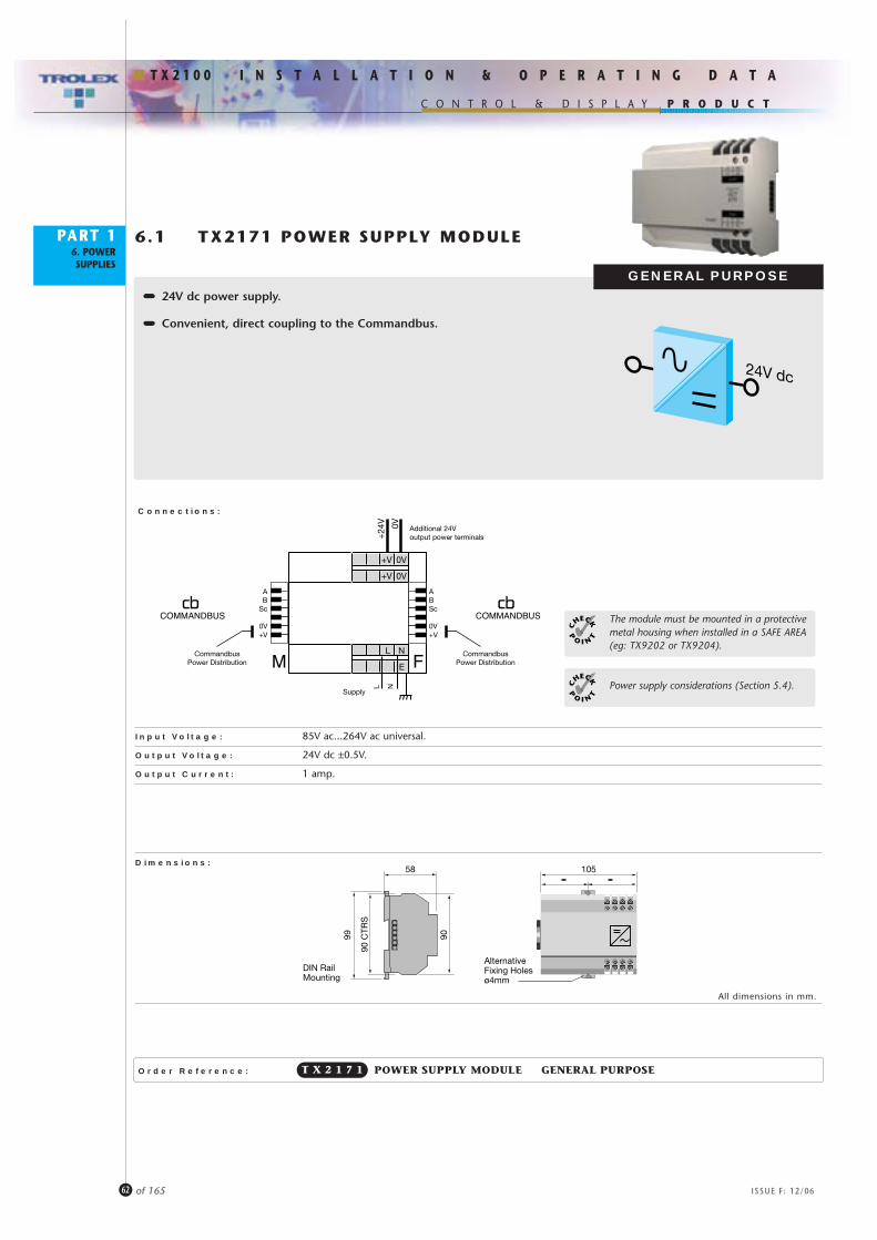
••••••••••••••• General purpose systems may be powered from a proprietaryexternal stabilised 24V dc power supply. It is only necessary to feed the power to the COMMAND MODULE as power is distributed to the remainder of the system through the COMMANDBUS.(Maximum total COMMANDBUS current: 6 Amps).
••••••••••••••• The TX2171 Power Supply provides a very convenient method of powering General Purpose systems. It couples directly onto the COMMANDBUS distributing a stabilised 24V dcsupply to the complete system through the Commandbus.
Several options are available to power Commander systems, the choice is dependent upon the type of
system being installed:
TX217124V dc 24V dc
acPower
P R O D U C T
ISSUE F: 12/06
I N S T A L L A T I O N & O P E R A T I N G D A T A
C O N T R O L & D I S P L A Y
T X 2 1 0 0
PART 16. POWER SUPPLIES
62 of 165
Order Reference:
6.1 TX2171 POWER SUPPLY MODULE
•••••••••••••••• 24V dc power supply.
•••••••••••••••• Convenient, direct coupling to the Commandbus.
GENERAL PURPOSE
POWER SUPPLY MODULE GENERAL PURPOSET X 2 1 7 1
Connections:
Input Voltage: 85V ac...264V ac universal.
Output Voltage: 24V dc ±0.5V.
Output Current: 1 amp.
Dimensions:
All dimensions in mm.
10558
AlternativeFixing Holesø4mm
99 90
90 C
TRS
DIN RailMounting
E
L N
0V+V
0V+V
L N
Supply
M F
ABSc 0V+V
AB
Sc
0V+V
+24
V 0V Additional 24Voutput power terminals
CommandbusPower Distribution
CommandbusPower Distribution
COMMANDBUSCOMMANDBUS
Power supply considerations (Section 5.4).
The module must be mounted in a protective metal housing when installed in a SAFE AREA(eg: TX9202 or TX9204).

P R O D U C T
ISSUE F: 12/06
I N S T A L L A T I O N & O P E R A T I N G D A T A
C O N T R O L & D I S P L A Y
T X 2 1 0 0
PART 18. COMMANDBUS
CABLES
63 of 165
8 commandbuscables

P R O D U C T
ISSUE F: 12/06
I N S T A L L A T I O N & O P E R A T I N G D A T A
C O N T R O L & D I S P L A Y
T X 2 1 0 0
PART 18. COMMANDBUS
CABLES
64 of 165
••••••••••••••• Commander modules are designed to be conveniently
close coupled together on a standard DIN rail using
the integral Commandbus connecting system.
••••••••••••••• Commandbus cables may be used to extend to locally
dispersed Commandbus groups:
••••••••••••••• Control panel wiring can be almost eliminated by connecting
incoming field cables directly to the Commander terminal modules.
Control room cabling can also be simplified by using the
Commandbus communication to interface with display systems.
SENSOR INPUTS
CONTROL OUTPUTS
• Power Supply Considerations (Section 5.4).

P R O D U C T
ISSUE F: 12/06
I N S T A L L A T I O N & O P E R A T I N G D A T A
C O N T R O L & D I S P L A Y
T X 2 1 0 0
PART 18. COMMANDBUS
CABLES
65 of 165
Order Reference:
8.1 COMMANDBUS CABLES
•••••••••••••••• Interconnecting cables and connectors for locally dispersed
Commandbus systems.
COMMANDBUS CABLE HEADER • FEMALE(Internal screw terminal connections)
T X 2 1 5 2
COMMANDBUS CABLE HEADER • MALE(Internal screw terminal connections)
T X 2 1 5 3
6 CORE (5 used) COMMANDBUS CABLE per metre(For use with TX2151, TX2152 and TX2153)
T X 2 1 5 4
DIN RAIL END CLAMPT X 2 1 5 8
END CLAMP WITH CABLE ANCHORCommandbus cable headers can be secured in positionby using the retainer provided on this end clamp
T X 2 1 5 9
ABSc 0V+V
AB
Sc
0V+V
F M
40.0
COMMANDBUS CABLE HEADER. MALE(Internal screw terminal connections).The housing of the connector is fitted with two retainingscrews for anchoring to the TX2104 Series CommandModules, panel mounting version.
T X 2 1 5 1
P R O D U C T
I N S T A L L A T I O N & O P E R A T I N G D A T A
C O N T R O L & D I S P L A Y
T X 2 1 0 0
PART 19. NAVIGATOR
MAP
66 of 165 ISSUE F: 12/06
9 navigator map
P R O D U C T
I N S T A L L A T I O N & O P E R A T I N G D A T A
C O N T R O L & D I S P L A Y
T X 2 1 0 0
PART 19. NAVIGATOR
MAP
67 of 165 ISSUE F: 12/06
•••••••••••••••A
t p
ow
er u
p,
the
Tro
lex
log
o w
ill p
rog
ress
ivel
y ap
pea
r o
n t
he
com
man
d m
od
ule
dur
ing
th
e p
roce
sso
r se
lf-t
est
and
init
ialis
ing
ro
utin
e, f
ollo
wed
imm
edia
tely
by
the
BA
SE d
isp
lay
in t
he
read
out
zo
ne
(sec
tio
n 1
0.1)
.
•••••••••••••••Tr
aver
se t
he
Nav
igat
or
Map
usi
ng
th
e N
AV
IGA
TOR
KEY
PAD
.
Each
key
op
erat
ion
will
clic
k:
BASE
(Sec
tion
10.1
)
SECU
RITY
BAR
RIER
(Sec
tion
11)
READ
OUT
ZO
NE (S
ectio
n 10
)SE
TUP
ZONE
(Sec
tion
12)
COM
MAN
D M
ODU
LESE
TUP
(Sec
tion
12.1
)
INDI
VIDU
ALLO
CATI
ON
SETU
P(S
ectio
n 12
.2)
INDI
VIDU
ALDA
TA(S
ectio
n 10
.5)
INDI
VIDU
ALRE
ADO
UT(S
ectio
n 10
.2)
INDI
VIDU
ALTR
END
(Sec
tion
10.4
)
INDI
VIDU
ALM
INM
AX(S
ectio
n 10
.3)

P R O D U C T
I N S T A L L A T I O N & O P E R A T I N G D A T A
C O N T R O L & D I S P L A Y
T X 2 1 0 0
PART 110. READOUT
ZONE
68 of 165 ISSUE F: 12/06
10 readout zone
P R O D U C T
I N S T A L L A T I O N & O P E R A T I N G D A T A
C O N T R O L & D I S P L A Y
T X 2 1 0 0
PART 110. READOUT
ZONE
69 of 165 ISSUE F: 12/06
: Scroll N/S to a selected location.
: Key and hold for rapid auto keying.
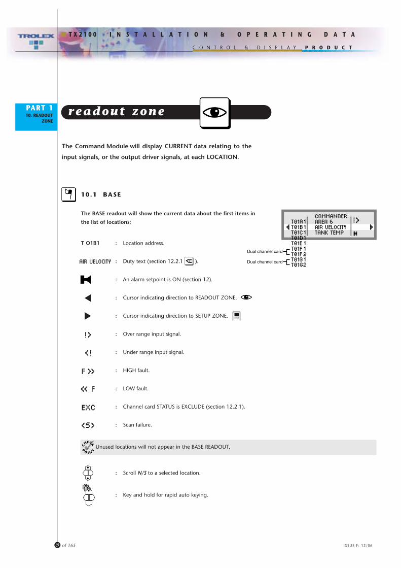
The Command Module will display CURRENT data relating to the
input signals, or the output driver signals, at each LOCATION.
readout zone
10.1 BASE
The BASE readout will show the current data about the first items in
the list of locations:
T O1B1 : Location address.
: Duty text (section 12.2.1 ).
: An alarm setpoint is ON (section 12).
: Cursor indicating direction to READOUT ZONE.
: Cursor indicating direction to SETUP ZONE.
: Over range input signal.
: Under range input signal.
: HIGH fault.
: LOW fault.
: Channel card STATUS is EXCLUDE (section 12.2.1).
: Scan failure.
Unused locations will not appear in the BASE READOUT.
Dual channel card
Dual channel card

P R O D U C T
I N S T A L L A T I O N & O P E R A T I N G D A T A
C O N T R O L & D I S P L A Y
T X 2 1 0 0
PART 110. READOUT
ZONE
70 of 165 ISSUE F: 12/06
10.2 INDIVIDUAL READOUT
Step W for a more detailed readout of a selected location.
T 01B1 : Location address (Terminal module '01'/LOCATION 'B1').
: Duty text (section 12.2.1 ).
: Type of channel card (section 4).
25m/s : Signal status with units (section 12.2.1).
: Bar graph of input signal STATIC.
: Bar graph of input signal INCREASING TENDENCY.
: Bar graph of input signal DECREASING TENDENCY.
: Setpoint 1 marker (section 12.2.1) denoting an UNDER alarm.: Setpoint 2 marker (section 12.2.1) denoting an OVER alarm.
: SETPOINT 1 activated (ON) (section 12.2.1).
: SETPOINT 2 activated (ON) (section 12.2.1).
: LOWER SCALE MEASURING value (section 12.2.1 ).
: UPPER SCALE MEASURING value (section 12.2.1 ).
: SETPOINT 1 value (section 12.2.1 ).
: SETPOINT 2 value (section 12.2.1 ).
: Channel card STATUS is EXCLUDE (section 12.2.1).
: Scan failure.
Scroll N/S to other individual locations.

P R O D U C T
I N S T A L L A T I O N & O P E R A T I N G D A T A
C O N T R O L & D I S P L A Y
T X 2 1 0 0
PART 110. READOUT
ZONE
71 of 165 ISSUE F: 12/06
UNDER RANGE/OVER RANGE INPUT
Indication will be given if the input signal on a particular channel location
transgresses beyond the normal operating range:
••••••••••••••••••• The Analogue input signal level is UNDER RANGE.
••••••••••••••••••• The Analogue input signal level is OVER RANGE.
FAULT INPUT
Indication will be given if the input signal on a particular channel location
transgresses beyond 10% above or below the normal operating range.
A FAULT alarm state will also be initiated
(section 12.2.1 / 12.2.2 / 12.2.3 / 12.2.4 / 12.2.5 ):
••••••••••••••••••• The Analogue input signal level is LOW FAULT.
••••••••••••••••••• The Analogue input signal level is HIGH FAULT.
eg: Below 4mA
eg: Above 20mA
eg: Below 3.6mA
eg: Above 22mA

P R O D U C T
I N S T A L L A T I O N & O P E R A T I N G D A T A
C O N T R O L & D I S P L A Y
T X 2 1 0 0
PART 110. READOUT
ZONE
72 of 165 ISSUE F: 12/06
10.4 INDIVIDUAL TREND
Step W for historical trend graph (Hold for accelerated stepping).
: Duty text (section 12.2.1).
: Log number.
: Setpoint 2 (section 12.2.1).
: Setpoint 1 (section 12.2.1).
: Cursor (section 10.5).
: Zero baseline.
: Century marker. The display graph represents 100 logged
readings. Each increment represent the next 100 readings.
Total maximum logged readings: 4000.
Scroll N/S to TRAVERSE the cursor (Key and hold for self scrolling).
10.5 INDIVIDUAL DATA
Step W for details of the data present at the cursor
position selected (section 10.4).
This data is recorded in the log (section 12.1.5).
Additional EVENT data is also displayed and recorded as shown.
: Fault condition.
: Alarm event.
10.3 INDIVIDUAL MINMAX
Step W for details of the MINIMUM and MAXIMUM measured values
attained since last reset (section 12.2.1 ).
: Duty text (section 12.2.1).
: Maximum.
: Minimum.
• Setpoint 1 and Setpoint 2 are PRESENT values only.
• When the cursor reaches one of the extremities of a display field it will transfer to the mid-point of thesucceeding display field.
F
Step E to return.
(Key and hold for scroll).

P R O D U C T
I N S T A L L A T I O N & O P E R A T I N G D A T A
C O N T R O L & D I S P L A Y
T X 2 1 0 0
PART 111. SECURITY
BARRIER
73 of 165 ISSUE F: 12/06
11 security barrier

P R O D U C T
I N S T A L L A T I O N & O P E R A T I N G D A T A
C O N T R O L & D I S P L A Y
T X 2 1 0 0
PART 111. SECURITY
BARRIER
74 of 165 ISSUE F: 12/06
Attempts to step EAST into the SETUP ZONE will be halted if the security
barrier is closed. Enter the KEYCODE to open the barrier:
security barrier
Scroll E/W to TRAVERSE the digits.
Scroll N/S to CHANGE the digits.
Step E to PASS into the setup zone.
This routine will not appear if the security barrier is open (section 12.1.1).

P R O D U C T
I N S T A L L A T I O N & O P E R A T I N G D A T A
C O N T R O L & D I S P L A Y
T X 2 1 0 0
PART 112. SETUP ZONE
75 of 165 ISSUE F: 12/06
12 setup zone

P R O D U C T
I N S T A L L A T I O N & O P E R A T I N G D A T A
C O N T R O L & D I S P L A Y
T X 2 1 0 0
PART 112. SETUP ZONE
76 of 165 ISSUE F: 12/06
Conventions during the SETUP routines:
Step E to CONFIRM data (followed by AUTOMATIC RETURN to menu).
Step W to EXIT data.
Step W to RETURN to BASE.
setup zone
ENTER THE REQUIRED SETUPS BY USING THE COMMAND
MODULE NAVIGATOR KEYPAD
The complete setup can also be installed directly into the
Command Module through the LAN 1 or LAN 2
data ports, using the TX2199 Commander Configuration
Software Package (section 13).
The fundamental operating characteristics of the Commander System can
be SETUP as preferred.
The first SETUP task is:
12.1 COMMAND MODULE SETUP
followed by
12.2 INDIVIDUAL LOCATION SETUPS

P R O D U C T
I N S T A L L A T I O N & O P E R A T I N G D A T A
C O N T R O L & D I S P L A Y
T X 2 1 0 0
PART 112. SETUP ZONE
77 of 165 ISSUE F: 12/06
12.1 COMMAND MODULE SETUP
Start ing from BASE (section 10.1).
The security barrier may be closed at this point and deny access.(section 11).
Scroll N/S to COMMANDER.
Step E to the COMMAND MODULE setup.
Scroll the cursor E/W to SELECT.
Step N to CONFIRM.
12.1.1
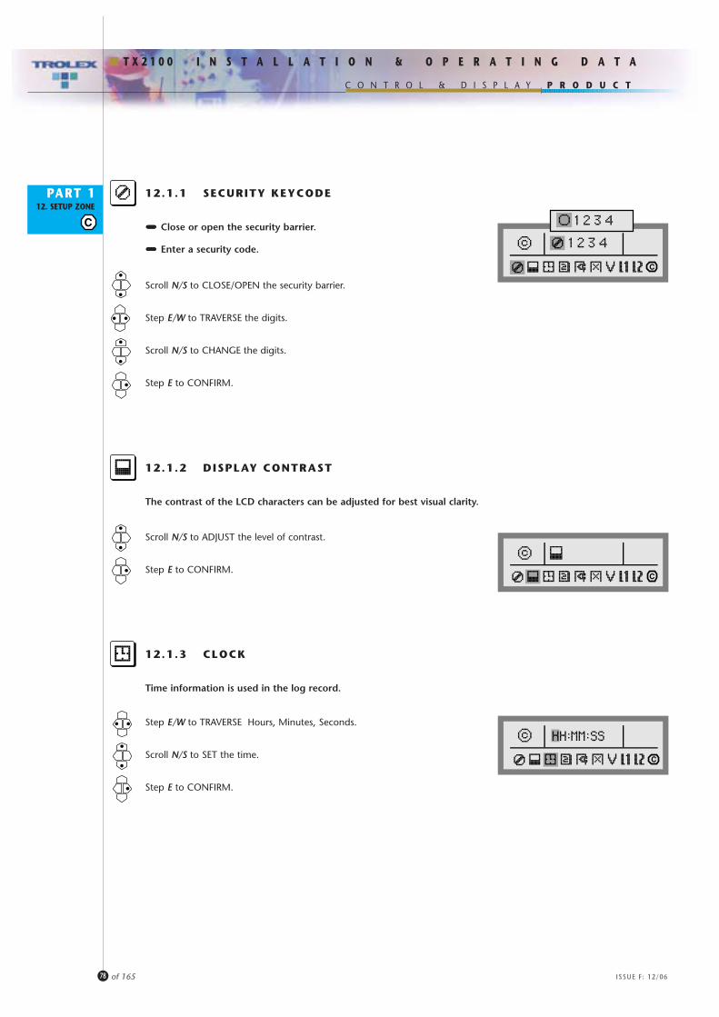
P R O D U C T
I N S T A L L A T I O N & O P E R A T I N G D A T A
C O N T R O L & D I S P L A Y
T X 2 1 0 0
PART 112. SETUP ZONE
78 of 165 ISSUE F: 12/06
12.1.1 SECURITY KEYCODE
Scroll N/S to CLOSE/OPEN the security barrier.
Step E/W to TRAVERSE the digits.
Scroll N/S to CHANGE the digits.
Step E to CONFIRM.
••••••••••••••••••• Close or open the security barrier.
••••••••••••••••••• Enter a security code.
12.1.2 DISPLAY CONTRAST
Scroll N/S to ADJUST the level of contrast.
Step E to CONFIRM.
The contrast of the LCD characters can be adjusted for best visual clarity.
12.1.3 CLOCK
Step E/W to TRAVERSE Hours, Minutes, Seconds.
Scroll N/S to SET the time.
Step E to CONFIRM.
Time information is used in the log record.
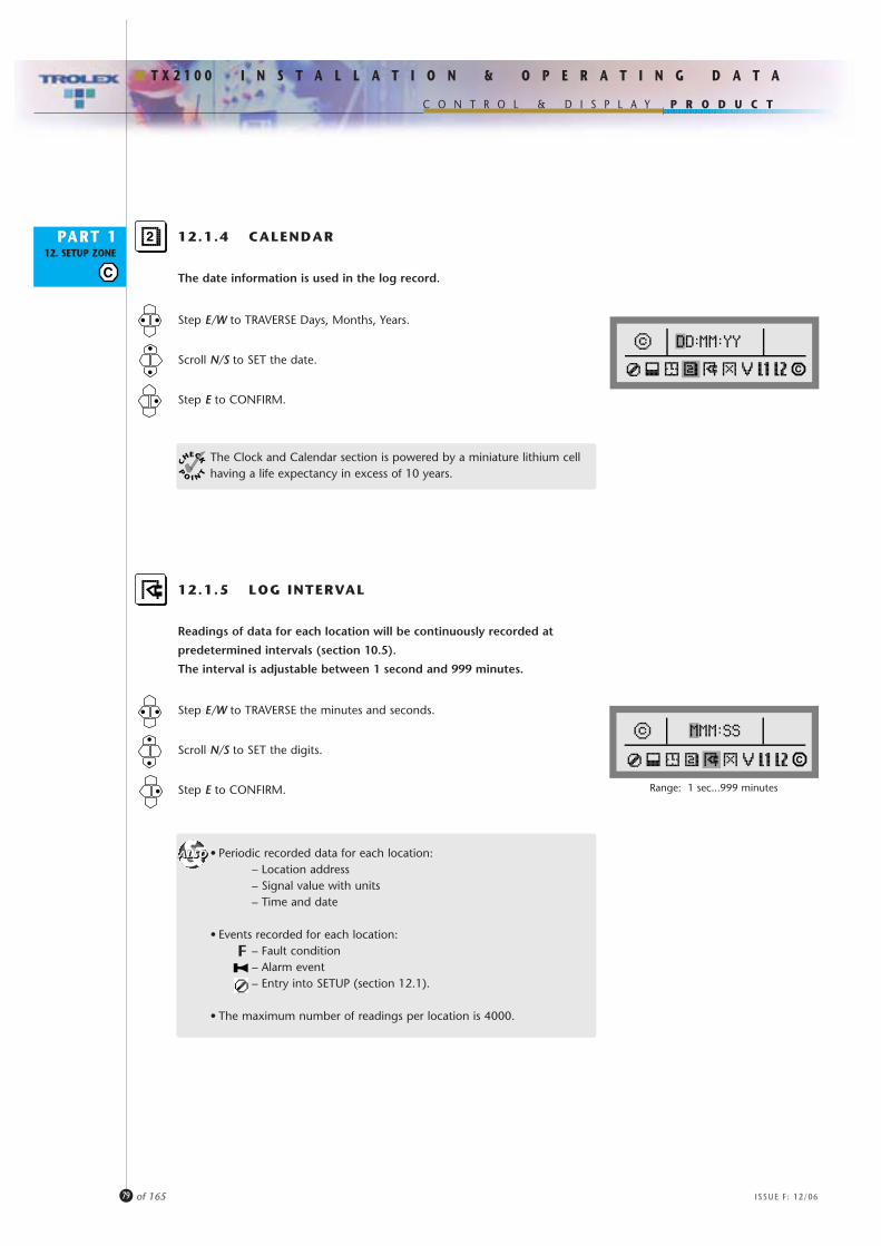
P R O D U C T
I N S T A L L A T I O N & O P E R A T I N G D A T A
C O N T R O L & D I S P L A Y
T X 2 1 0 0
PART 112. SETUP ZONE
79 of 165 ISSUE F: 12/06
12.1.4 CALENDAR
Step E/W to TRAVERSE Days, Months, Years.
Scroll N/S to SET the date.
Step E to CONFIRM.
The date information is used in the log record.
The Clock and Calendar section is powered by a miniature lithium cell having a life expectancy in excess of 10 years.
12.1.5 LOG INTERVAL
Step E/W to TRAVERSE the minutes and seconds.
Scroll N/S to SET the digits.
Step E to CONFIRM.
Readings of data for each location will be continuously recorded at
predetermined intervals (section 10.5).
The interval is adjustable between 1 second and 999 minutes.
• Periodic recorded data for each location:– Location address– Signal value with units– Time and date
• Events recorded for each location:– Fault condition– Alarm event– Entry into SETUP (section 12.1).
• The maximum number of readings per location is 4000.
Range: 1 sec...999 minutes
F
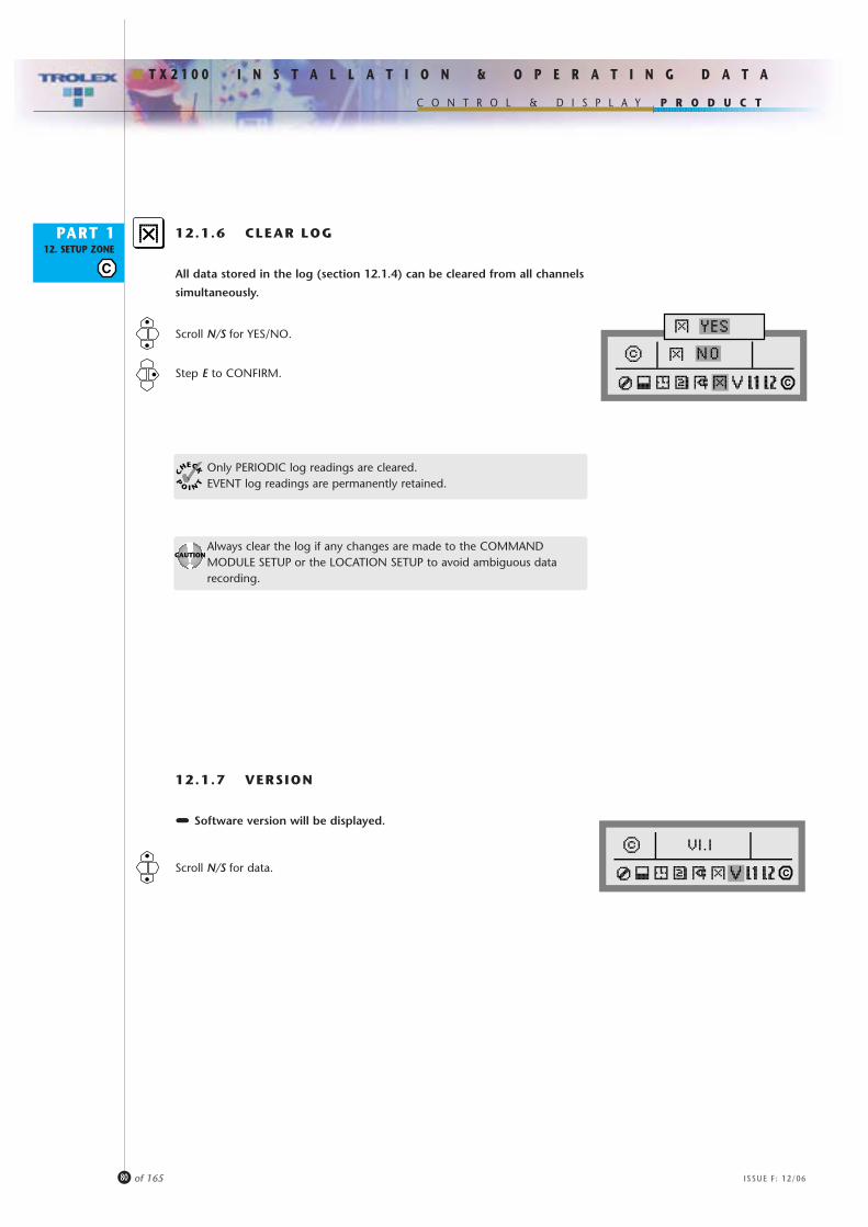
P R O D U C T
I N S T A L L A T I O N & O P E R A T I N G D A T A
C O N T R O L & D I S P L A Y
T X 2 1 0 0
PART 112. SETUP ZONE
80 of 165 ISSUE F: 12/06
12.1.6 CLEAR LOG
Scroll N/S for YES/NO.
Step E to CONFIRM.
All data stored in the log (section 12.1.4) can be cleared from all channels
simultaneously.
Always clear the log if any changes are made to the COMMANDMODULE SETUP or the LOCATION SETUP to avoid ambiguous data recording.
12.1.7 VERSION
••••••••••••••••••• Software version will be displayed.
Scroll N/S for data.
Only PERIODIC log readings are cleared.EVENT log readings are permanently retained.

P R O D U C T
I N S T A L L A T I O N & O P E R A T I N G D A T A
C O N T R O L & D I S P L A Y
T X 2 1 0 0
PART 112. SETUP ZONE
81 of 165 ISSUE F: 12/06
PROTOCOL MODBUS COMMANDER CONTROL
Stopbits: 1/2
Parity: None/Odd/Even
Baud Rate: 300/600/1200/2400/4800/9600 / 14K4/19K2/28K8/38K4/57K6/115K2
Address 1 to 250 (protocol dependent)
TX On: 0.1 – 99ms
TX Off: 0.1 – 99ms
Monitor Timeout: OFF/1sec/5sec/10sec/30sec/60sec
Monitor Assign:
12.1.8 LAN 1 DATACOMMS
12.1.9 LAN 2 DATACOMMS
Scroll N/S to SELECT.
Step E to ENTER.
The protocol characteristics required for the LAN 1 and LAN 2 datacomms
can be individually setup. This is only necessary where Commander is being
integrated into a wider communication network, to interface with a PC or
user display.
Step E to CONFIRM
Scroll N/S to
DEFINE values
PROTOCOL SELECTION
The standard communication protocol is MODBUS (BINARY).
A COMMANDER CONTROL option is also available for use with the TX2199
Commander Configuration Software Package (section 13) or for interfacing
with special control programmes which may be installed in the Command
Module.
There is also an option to disable the LAN input completely when required.
Scroll N/S to SELECT.
Step E to CONFIRM.

P R O D U C T
I N S T A L L A T I O N & O P E R A T I N G D A T A
C O N T R O L & D I S P L A Y
T X 2 1 0 0
PART 1
82 of 165 ISSUE F: 12/06
12. SETUP ZONECOMMUNICATIONS MONITOR
The integrity of the LAN1/LAN2 MODBUS communication link can be
monitored over successive periods. The period can be selected from 1 second
up to 60 seconds or OFF.
If a communications failure is detected, an alarm can be assigned to any
selected channel card location.
ASSIGNING A COMMS MONITOR FAILURE ALARM
AssignationIdentity
ChannelAddress
Executionat the assigned
destination
�B
�:GO
✘:RESET
10T 1Destination
Address
0...30
Constant
(Terminal module)
C(The setpoint isassigned to the
Command Modulefor use in a specific
program).
Input location atthe channel
address
Single
Dual
1
1
1
2
234
Quad
CONFIGURE
Scroll N/S for YES/NO.
Step E to CONFIRM.
When a Commander system has been assembled and loaded with channel cards,
the Command Module must be instructed to scan the system to automatically
identify (REFRESH) the type of card at each location and number of Terminal
Modules fitted in that system.
The same goes for a system that has been modified.
To avoid confusion, this function is only executed when instructed to do so by
the user.
FIXED: No REFRESH at any time.
REFRESH NOW: REFRESH when CONFIRMED from the keypad.
RFSH AT BOOT: REFRESH whenever the Commander system is switched ON.
A latchedoutput relay
(section12.2.4 )

P R O D U C T
I N S T A L L A T I O N & O P E R A T I N G D A T A
C O N T R O L & D I S P L A Y
T X 2 1 0 0
PART 112. SETUP ZONE
83 of 165 ISSUE F: 12/06
Start ing from BASE (section 10.1).
The security barrier may be closed at this pointand deny access (section 11).
Scroll N/S to selected LOCATION.
Step E to LOCATION setup.
The SETUP menu offered will vary depending upon which type of channel card is present at the location selected.
• A SINGLE FUNCTION channel cardLOCATION ADDRESS(section 3).
• A DUAL FUNCTION channel cardLOCATION ADDRESSES, (section 3).
• A QUAD FUNCTION channel cardLOCATION ADDRESSES, (section 3).
12.2 INDIVIDUAL LOCATION SETUPS
ANALOGUE INPUTCHANNEL CARDS
12.2.1 12.2.2 12.2.3 12.2.4 12.2.5
PULSE FREQUENCY INPUTCHANNEL CARDS
ONOFF/STATE INPUTCHANNEL CARDS
ONOFF/STATE OUPUTCHANNEL CARDS
ANALOGUE OUTPUTCHANNEL CARDS
Dual channel card
CONFIGURATION OF CHANNEL CARDSChannel card locations are automatically identified and addressed by the Command Module dependent, upon the position that they take up in a Commander System (section 4).To avoid confusion, this function is only executed when instructed to do so by the user (section 12 ).

P R O D U C T
I N S T A L L A T I O N & O P E R A T I N G D A T A
C O N T R O L & D I S P L A Y
T X 2 1 0 0
PART 112. SETUP ZONE
12.2.1
84 of 165 ISSUE F: 12/06
12.2.1 ANALOGUE INPUT CHANNEL CARDS
Scroll E/W to SELECT.
Step N to CONFIRM.
Units
Channel Card Type
Setpoint 2
Setpoint 2 activated (ON)
Setpoint 2 ON State
Upper Scale
Decimal Point
Text
Location AddressSetpoint 1 activated (ON)
Signal
Setpoint 1
Setpoint 1 ON State
Signal Bargraph
Lower Scale
FAULT conditions will also be displayed (section 10.2).

P R O D U C T
I N S T A L L A T I O N & O P E R A T I N G D A T A
C O N T R O L & D I S P L A Y
T X 2 1 0 0
PART 112. SETUP ZONE
12.2.1
85 of 165 ISSUE F: 12/06
CURRENT & VOLTAGECHANNEL CARDS
TX2141.301 (4...20mA)
TX2141.302(Dual 4...20mA)
TX2141.303(0.4...2V)
TX2141.304(Dual 0.4...2V)
TX2141.309 (ac)
SCALING
Step N/S to SELECT.
Step E to CONFIRM.
••••••••••••••••••• The various characteristics of the analogue input scale values can be determined.
••••••••••••••••••• The setup menu offered will vary depending upon which ANALOGUE channel card is present at the location
selected.
TEMPERATURECHANNEL CARDS
TX2141.306(PT100)
TX2141.307 (Dual PT100.)
TX2141.308 (Dual semicon.)
mVCHANNEL CARDS
TX2141.310 (mV)

P R O D U C T
I N S T A L L A T I O N & O P E R A T I N G D A T A
C O N T R O L & D I S P L A Y
T X 2 1 0 0
PART 112. SETUP ZONE
12.2.1
86 of 165 ISSUE F: 12/06
Lower
Independently adjustable, these two items are closely inter-related. They set the
desired LOWER limit and UPPER limit of the display reading for a given
magnitude of input signal span. This can be any numeric value and the polarity
can be any negative value through to any positive value. The indicating 'range'
from zero to full scale of the display can be programmed to show 'true' unit
values incorporating multiplication factors or zero offset values.
Upper
InputSignal 20mA
4mA
50barPressure0
Step E/W to TRAVERSE the cursor.
Scroll N/S to SCROLL the digits.
Step E to CONFIRM.
Independently adjustable, these two items are closely inter-related. They set the
desired LOWER limit and UPPER limit of the display reading for a given
magnitude of input signal span. This can be any numeric value and the polarity
can be any negative value through to any positive value. The indicating 'range'
from zero to full scale of the display can be programmed to show 'true' unit
values incorporating multiplication factors or zero offset values.
This relates engineering units to the basic measured signal range.
• The signal response between LOWER and UPPER will be assumed to be linear.
• Signals from non-conforming devices such as temperature sensors willbe automatically linearised to the appropriate standard.
Range: –9999.9 ... +9999.9with decimal point
Temperature channel cards, TX2141.306 / TX2141.307 / TX2141.308 will always measure the specified range. The VISIBLE DISPLAY range can be 'offset' if required (sections 4.1.6, 4.1.7 and 4.1.8).

P R O D U C T
I N S T A L L A T I O N & O P E R A T I N G D A T A
C O N T R O L & D I S P L A Y
T X 2 1 0 0
PART 112. SETUP ZONE
12.2.1
87 of 165 ISSUE F: 12/06
Scroll N/S to SELECT.
Step E to CONFIRM.
A menu of standard engineering units is available for adding on to the signal
value display to define the actual parameter being measured,
eg. bar, mA, m/sec, °C, etc.
UNITS
Step E/W to TRAVERSE the characters.
Scroll N/S to SET.
Step E to CONFIRM.
An option called USER will appear in the units menu choice.
Specific user defined units can be configured. Up to 4 digits of text can be
entered into the display and there is a menu of letters, numbers and symbols
to choose from.
The INPUT SIGNAL is sampled at pre-determined intervals and the update
time period is adjustable. Signal values are AVERAGED between samples.
A low setting will give rapid reaction to the input signal and higher settings
may be entered where damping of a fluctuating input is necessary, or simply
as a means of applying a delay to the input. This is particularly appropriate in
electrically noisy environments.
UPDATE
Magnitude comparisons of each successive UPDATE will determine the status of the input signal.
Step E/W to TRAVERSE the cursor.
Scroll N/S to SET the value.
Step E to CONFIRM.
STABLE
INCREASING
DECREASING
UPDATETIME
Menu:V, mV, A, mA, °C, °F, °K, g, kg, mbar,bar, Pa, kPa, PSI, %, ppm, %RH, mm,m, mm/s, m/s, m3/s, m3/m, m3/h, l/s,l/m, l/h, g/s, g/m, g/h, kg/s, kg/m,kg/h, rpm, pps, Hz, kHz, secs, mins, hrs,USER.
Range: 0.1 ... 60 seconds
For temperature cards only °C, °F and °K are offered.

P R O D U C T
I N S T A L L A T I O N & O P E R A T I N G D A T A
C O N T R O L & D I S P L A Y
T X 2 1 0 0
PART 112. SETUP ZONE
12.2.1
88 of 165 ISSUE F: 12/06
Step E/W to TRAVERSE the digits.
Scroll N/S to SET the digits.
Step E to CONFIRM.
This additional item will appear in the menu when a mV input location is
selected for SETUP.
The TX2141.312 channel card provides a regulated variable output
current for powering sensors and strain gauges.
The output current may be set to concur with that of the sensing device
being used (section 4.1.10).
OUTPUT VOLTAGE
Adjust the current to the correct value using a suitable meter BEFORE connecting the sensor.
Range: 0...50mA
The output of the mV supply card is self regulating and will automatically limit if it is operated beyond its rated parameters.

P R O D U C T
I N S T A L L A T I O N & O P E R A T I N G D A T A
C O N T R O L & D I S P L A Y
T X 2 1 0 0
PART 112. SETUP ZONE
12.2.1
89 of 165 ISSUE F: 12/06
Step E/W to TRAVERSE the characters.
Scroll N/S to SET the characters.
Step E to CONFIRM.
Duty Text can be entered to denote the Input duty, the location or the
tag reference of the input device.
Up to 12 digits of text can be entered into the display and there is a
menu of Letters, Numbers and Symbols to choose from.
TEXT
A default message will appear if no user text is entered.

P R O D U C T
I N S T A L L A T I O N & O P E R A T I N G D A T A
C O N T R O L & D I S P L A Y
T X 2 1 0 0
PART 112. SETUP ZONE
12.2.1
90 of 165 ISSUE F: 12/06
SETPOINT 1
Step N/S to SELECT.
Step E to CONFIRM.
SETPOINT 2
••••••••••••••••••• Each input channel location has two individual SETPOINTS (SP1 and
SP2) which can be activated ON for ALARM or CONTROL functions.
••••••••••••••••••• The various operating response characteristics of each setpoint can
be individually setup.
••••••••••••••••••• Setpoint ON states are transferred onto the Commandbus and can
be assigned to selected output driver channel locations to INITIATE
field output actions.
••••••••••••••••••• A setpoint that is activated ON = ALARM or CRITICAL condition.
Input
P R O D U C T
I N S T A L L A T I O N & O P E R A T I N G D A T A
C O N T R O L & D I S P L A Y
T X 2 1 0 0
PART 112. SETUP ZONE
12.2.1
91 of 165 ISSUE F: 12/06
Scroll E/W to TRAVERSE the cursor.
Scroll N/S to SET the digit.
Step E to CONFIRM.
The ON level of the setpoint can be setup. This can be set for any numerical
value and the polarity can be positive or negative as required.
LEVEL
Scroll E/W to TRAVERSE the cursor.
Scroll N/S to SET the digit.
Step E to CONFIRM.
The Hysteresis is the DEADBAND between the setpoint ACTIVATING ON and
ACTIVATING OFF as the input signal increases and decreases.
The OFF level can be defined with respect to the ON setpoint (section 12.2.1 ).
• OFF level values less than the ON level.
• OFF level values greater than the ON level.
HYSTERESIS
A low value of hysteresis, is often used to override fluctuating signal levels and
to prevent 'hunting' in closed loop control systems.
A high value of hysteresis can also be used as a control function as when
controlling the operation of pumps. The pump will start at high level and
continue pumping until low level is reached at the bottom of the hysteresis
band.
Setpoint
0
–
+
ON
OFFInput Signal
OVER setpoint
High
Low
Range limited to the LOWER and UPPERvalues setup (section )
OFF
ON
Input Signal
UNDER setpoint

P R O D U C T
I N S T A L L A T I O N & O P E R A T I N G D A T A
C O N T R O L & D I S P L A Y
T X 2 1 0 0
PART 112. SETUP ZONE
12.2.1
92 of 165 ISSUE F: 12/06
The setpoint can be setup to be ON when the input signal is OVER the
setpoint level or ON when the input signal is UNDER the setpoint level.
For example; when monitoring overspeed on a conveyor, the setpoint can be
set to be ON when the level of the input signal from the sensor is OVER the
setpoint value to give a failsafe alarm function.
Conversely, when monitoring underspeed, the setpoint can be set to be ON
when the input signal from the sensor is UNDER the setpoint.
ON ACTIVATE
Step N/S to SELECT.
Step E to CONFIRM.
Both modes can be combined using the two setpoints (SP1 and SP2) toprovide boundary protection.
ON DELAY
Step E/W to TRAVERSE the digits.
Scroll N/S to SET the time t.
Step E to CONFIRM.
The activation ON of the setpoint can be delayed by an adjustable time period
(t ON). This is useful for alarm verification, to apply time delay in a process
control action, or to override a spurious fluctuation of the input signal.
The activation OFF of the setpoint can also be delayed by an adjustable time
period (t OFF).
If the input signal recedes from the setpoint level before the time has elapsed,
the timer will reset to zero, ready to start again.
OFF DELAY
Both t ON and t OFF can be Combined.
Setpoint
ON
ONONUNDER activate
OVER activate
OFF
ON
ON
OFF
ON
OFF
OFF ON OFF
ON
OFF
Range: 0 ... 255 seconds
OVERUNDER
P R O D U C T
I N S T A L L A T I O N & O P E R A T I N G D A T A
C O N T R O L & D I S P L A Y
T X 2 1 0 0
PART 112. SETUP ZONE
12.2.1
93 of 165 ISSUE F: 12/06
Scroll N/S to SELECT the address identities available.
Step E/W to TRAVERSE the address.
Scroll N/S to SET � or ✘.
Step E to CONFIRM.
••••••••••••••••••• A SETPOINT ON state is transferred onto the Commandbus.
••••••••••••••••••• It can be SETUP to be ASSIGNED to a choice of up to 8 ONOFF/STATE
output channel card location addresses to initiate action.
••••••••••••••••••• All potential destination addresses available in the Commander system
(including the Command Module) can be sequentially presented on
the display and selected as desired.
ASSIGN
��
InputSignal
OutputAlarm
ASSIGNATIONS
AssignationIdentity
ChannelAddress
Executionat the assigned
destination
�B
�:GO
✘:RESET
10T 1Destination
Address
0...30
Constant
(Terminal module)
C(The setpoint isassigned to the
Command Modulefor use in a specific
program).
Input location atthe channel
address
Single
Dual
1
1
1
2
234
QuadA latched
output relay(section
12.2.4 )

P R O D U C T
I N S T A L L A T I O N & O P E R A T I N G D A T A
C O N T R O L & D I S P L A Y
T X 2 1 0 0
PART 112. SETUP ZONE
12.2.1
94 of 165 ISSUE F: 12/06
Scroll N/S to SELECT the address identities available.
Step E/W to TRAVERSE the address.
Scroll N/S to SET � or ✘.
Step E to CONFIRM.
••••••••••••••••••• Each channel card location will give a common FAULT output state for:
• Analogue input signal UNDER RANGE (section 10.2).
• Analogue input signal OVER RANGE (section 10.2).
• Analogue signal LOW FAULT (section 10.2).
• Analogue signal HIGH FAULT (section 10.2).
• Sensor fault.
• Channel card fault.
••••••••••••••••••• The FAULT state is transferred onto the Commandbus.
••••••••••••••••••• It can be SETUP to be ASSIGNED to a choice of up to 8 ONOFF/ output
channel card location addresses to initiate action.
••••••••••••••••••• All potential destination addresses available in the Commander system
(including the Command Module) can be sequentially presented on
the display and selected as desired.
ASSIGN FAULT
Fault
OutputAlarm
ASSIGNATIONS
AssignationIdentity
ChannelAddress
Executionat the assigned
destination
�A
�:GO
✘:RESET
16T 1Destination
Address
0...30
Constant
(Terminal module)
C(The setpoint isassigned to the
Command Modulefor use in a specific
program).
Input location atthe channel
address
Single
Dual
1
1
1
2
234
QuadA latched
output relay(section
12.2.4 )

P R O D U C T
I N S T A L L A T I O N & O P E R A T I N G D A T A
C O N T R O L & D I S P L A Y
T X 2 1 0 0
PART 112. SETUP ZONE
12.2.1
95 of 165 ISSUE F: 12/06
Scroll N/S to SELECT.
Step E to CONFIRM.
As a result of plant maintenance, it may be necessary to temporarily
disable a particular channel card location.
The location can be properly EXCLUDED to prevent false alarm states
occurring.
STATUS
Reinstate INCLUDE after the interruption is over.
•Always EXCLUDE a channel card location when changing a channel card otherwise the Command module will perceive a FAULT.
•Remember that where a channel card that has been EXCLUDED and replaced, the new card will need to be first SETUP, INCLUDED and REFRESHED (section 12.2.1 )
P R O D U C T
I N S T A L L A T I O N & O P E R A T I N G D A T A
C O N T R O L & D I S P L A Y
T X 2 1 0 0
PART 112. SETUP ZONE
12.2.1
96 of 165 ISSUE F: 12/06
Scroll N/S for YES/NO.
Step E to CONFIRM.
The maximum value and minimum value that the signal has reached since the
last RESET, is stored.
Dangerously HIGH or LOW sensor conditions may have occurred previously
and this feature enables historic trends to be examined (section 10.3).
Stored values of previous MIN and MAX can be RESET to the current value.
MINMAX
Data will be recorded in the log(section 12.1.5 and section 9).

P R O D U C T
I N S T A L L A T I O N & O P E R A T I N G D A T A
C O N T R O L & D I S P L A Y
T X 2 1 0 0
PART 112. SETUP ZONE
12.2.2
97 of 165 ISSUE F: 12/06
12.2.2 PULSE FREQUENCY INPUT CHANNEL CARDS
Step E/W to SELECT.
Step N to CONFIRM.
UnitsChannel Card Type
Setpoint 2
Setpoint 2 ON State
Setpoint 2 activated (ON)Setpoint 1 activated (ON)Upper Scale
Mode Selected
Decimal Point
Text
Location Address
Setpoint 1
Setpoint 1 ON State
Signal Bargraph
Lower Scale
Signal

P R O D U C T
I N S T A L L A T I O N & O P E R A T I N G D A T A
C O N T R O L & D I S P L A Y
T X 2 1 0 0
PART 112. SETUP ZONE
12.2.2
98 of 165 ISSUE F: 12/06
Scroll N/S to SELECT.
Step E to CONFIRM.
••••••••••••••••••• This item will appear in the menu where a PULSE/FREQUENCY digital
input channel card is present at a location.
••••••••••••••••••• Each channel card has two inputs, P1 and P2, which are used in
different ways depending upon which PULSE mode is selected.
••••••••••••••••••• A pulse/frequency channel card can be setup into a choice of four
different pulse processing modes. The first task is to determine which
one is required before continuing with the SETUP.
••••••••••••••••••• Also setup for NAMUR input devices or simple SWITCHING input
devices . The input signal threshold voltage level can
also be setup on simple switch inputs to eliminate spurious signals
where background ‘noise’ levels are high.
MODE
P R O D U C T
I N S T A L L A T I O N & O P E R A T I N G D A T A
C O N T R O L & D I S P L A Y
T X 2 1 0 0
PART 112. SETUP ZONE
12.2.2
99 of 165 ISSUE F: 12/06
••••••••••••••••••• The FREQUENCY level or pulse rate on P1 is measured.
••••••••••••••••••• P2 is not used.
••••••••••••••••••• Speed monitoring, flow rates, etc.
••••••••••••••••••• Each SETPOINT is determined as an ABSOLUTE frequency value.
FREQUENCY
P1
0
••••••••••••••••••• The FREQUENCY level or pulse rate on P1 is compared with a FIXED
frequency value that is entered .
••••••••••••••••••• P2 is not used.
••••••••••••••••••• Each SETPOINT is determined as a PERCENTAGE frequency value.
••••••••••••••••••• The PERCENTAGE FREQUENCY mode is most often used for monitoring
the rotational speed of a machine shaft or speed measuring device by
determining the pulse rate from a toothed wheel attached to the shaft and
comparing it to a fixed reference speed.
••••••••••••••••••• Overspeed or underspeed can be detected and is assessed as a
percentage related to the NORMAL running speed (ie. 5% SLIP
FREQUENCY or 5% UNDERSPEED).
% FREQUENCY
P1
+ % S
lip
Normal R
unning Speed
– % Slip
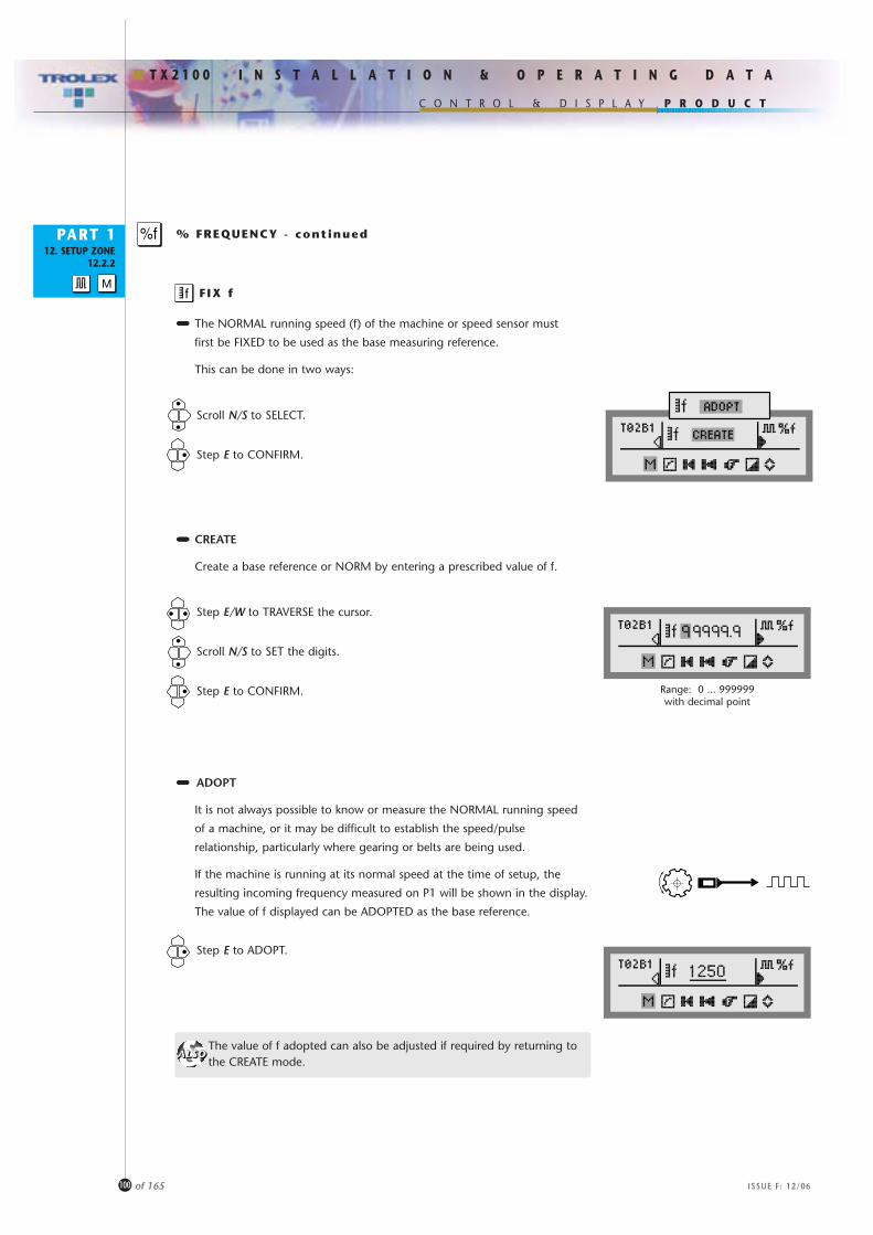
P R O D U C T
I N S T A L L A T I O N & O P E R A T I N G D A T A
C O N T R O L & D I S P L A Y
T X 2 1 0 0
PART 112. SETUP ZONE
12.2.2
100 of 165 ISSUE F: 12/06
FIX f
Scroll N/S to SELECT.
Step E to CONFIRM.
••••••••••••••••••• CREATE
Create a base reference or NORM by entering a prescribed value of f.
Step E/W to TRAVERSE the cursor.
Scroll N/S to SET the digits.
Step E to CONFIRM. Range: 0 ... 999999with decimal point
••••••••••••••••••• The NORMAL running speed (f) of the machine or speed sensor must
first be FIXED to be used as the base measuring reference.
This can be done in two ways:
••••••••••••••••••• ADOPT
It is not always possible to know or measure the NORMAL running speed
of a machine, or it may be difficult to establish the speed/pulse
relationship, particularly where gearing or belts are being used.
If the machine is running at its normal speed at the time of setup, the
resulting incoming frequency measured on P1 will be shown in the display.
The value of f displayed can be ADOPTED as the base reference.
Step E to ADOPT.
The value of f adopted can also be adjusted if required by returning to the CREATE mode.
% FREQUENCY - continued
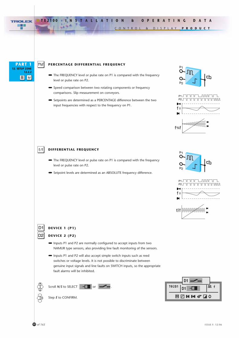
P R O D U C T
I N S T A L L A T I O N & O P E R A T I N G D A T A
C O N T R O L & D I S P L A Y
T X 2 1 0 0
PART 112. SETUP ZONE
12.2.2
101 of 165 ISSUE F: 12/06
••••••••••••••••••• The FREQUENCY level or pulse rate on P1 is compared with the frequency
level or pulse rate on P2.
••••••••••••••••••• Speed comparison between two rotating components or frequency
comparisons. Slip measurement on conveyors.
••••••••••••••••••• Setpoints are determined as a PERCENTAGE difference between the two
input frequencies with respect to the frequency on P1.
PERCENTAGE DIFFERENTIAL FREQUENCY
••••••••••••••••••• The FREQUENCY level or pulse rate on P1 is compared with the frequency
level or pulse rate on P2.
••••••••••••••••••• Setpoint levels are determined as an ABSOLUTE frequency difference.
DIFFERENTIAL FREQUENCY
0
P2P1
0
P2P1
••••••••••••••••••• Inputs P1 and P2 are normally configured to accept inputs from two
NAMUR type sensors, also providing line fault monitoring of the sensors.
••••••••••••••••••• Inputs P1 and P2 will also accept simple switch inputs such as reed
switches or voltage levels. It is not possible to discriminate between
genuine input signals and line faults on SWITCH inputs, so the appropriate
fault alarms will be inhibited.
DEVICE 1 (P1)
DEVICE 2 (P2)
Scroll N/S to SELECT or .
Step E to CONFIRM.

P R O D U C T
I N S T A L L A T I O N & O P E R A T I N G D A T A
C O N T R O L & D I S P L A Y
T X 2 1 0 0
PART 112. SETUP ZONE
12.2.2
102 of 165 ISSUE F: 12/06
Scroll N/S to SET the value.
Step E to CONFIRM.
••••••••••••••••••• When a simple switch input is selected, voltage THRESHOLD
adjustment will next be offered.
••••••••••••••••••• The input signal threshold voltage level can be set so that only pulse
amplitudes above a preset magnitude will be accepted by the input.
••••••••••••••••••• Background noise or spurious interference can be eliminated in this
way. This is particularly useful in a high speed, pulse processing system
where a simple time delay on the pulse would be unacceptably slow.
••••••••••••••••••• The default setting is 3.3V.
THRESHOLD
Threshold
Range: 0.5 ... 7.1V

P R O D U C T
I N S T A L L A T I O N & O P E R A T I N G D A T A
C O N T R O L & D I S P L A Y
T X 2 1 0 0
PART 112. SETUP ZONE
12.2.2
103 of 165 ISSUE F: 12/06
SCALING
Step N/S to SELECT.
Step E to CONFIRM.
••••••••••••••••••• The various characteristics of the DIGITAL input scale values can be determined.
••••••••••••••••••• The setup menu offered will also vary depending upon which PULSE MODE is selected for a channel card.
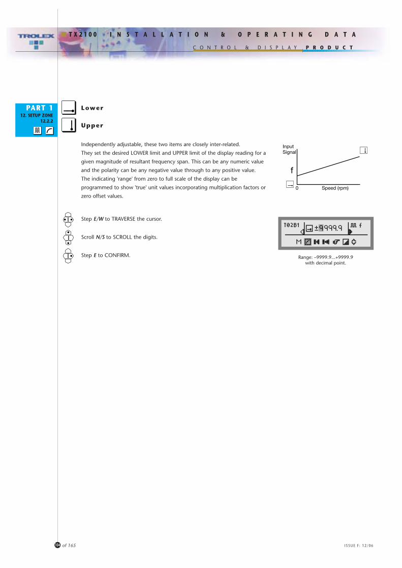
P R O D U C T
I N S T A L L A T I O N & O P E R A T I N G D A T A
C O N T R O L & D I S P L A Y
T X 2 1 0 0
PART 112. SETUP ZONE
12.2.2
104 of 165 ISSUE F: 12/06
Lower
Step E/W to TRAVERSE the cursor.
Scroll N/S to SCROLL the digits.
Step E to CONFIRM.
Independently adjustable, these two items are closely inter-related.
They set the desired LOWER limit and UPPER limit of the display reading for a
given magnitude of resultant frequency span. This can be any numeric value
and the polarity can be any negative value through to any positive value.
The indicating 'range' from zero to full scale of the display can be
programmed to show 'true' unit values incorporating multiplication factors or
zero offset values.
Upper
InputSignal
f
Speed (rpm)0
Range: –9999.9...+9999.9with decimal point.

P R O D U C T
I N S T A L L A T I O N & O P E R A T I N G D A T A
C O N T R O L & D I S P L A Y
T X 2 1 0 0
PART 112. SETUP ZONE
12.2.2
105 of 165 ISSUE F: 12/06
Scroll N/S to SELECT.
Step E to CONFIRM.
A menu of standard engineering units is available for adding on to the signal
value display to represent the actual parameter being measured, ie. Hz, l/m,
m/sec, etc.
UNITS
Step E/W to TRAVERSE the characters.
Scroll N/S to SET.
Step E to CONFIRM.
An option called USER will appear in the units menu choice. Specific user
defined units can be configured. Up to 4 digits of text can be entered into the
display and there is a menu of letters, numbers and symbols to choose from.
Automatic dual measuring mode is employed for optimum accuracy.
At low frequency rates the processor will determine the frequency by
measuring the period between successive pulses. It calculates an average over
the selected update period.
At higher frequencies the processor counts the pulses and calculates the mean
over the selected update period. The longer the update period, the more
accurate the displayed reading.
UPDATE
Magnitude comparisons of each successive UPDATE will determine the status of the input signal.
Step E/W to TRAVERSE the cursor.
Scroll N/S to SET the value.
Step E to CONFIRM.
STABLE
INCREASING
DECREASING
Update
Frequency
Range: 0.1 ... 60 seconds
Menu:V, mV, A, mA, °C, °F, °K, g, kg, mbar,bar, Pa, kPa, PSI, %, ppm, %RH, mm,m, mm/s, m/s, m3/s, m3/m, m3/h, l/s,l/m, l/h, g/s, g/m, g/h, kg/s, kg/m,kg/h, rpm, pps, Hz, kHz, secs, mins, hrs,USER.

P R O D U C T
I N S T A L L A T I O N & O P E R A T I N G D A T A
C O N T R O L & D I S P L A Y
T X 2 1 0 0
PART 112. SETUP ZONE
12.2.2
106 of 165 ISSUE F: 12/06
Step E/W to TRAVERSE the characters.
Scroll N/S to SET the characters.
Step E to CONFIRM.
Duty Text can be entered to denote the Input duty, the location or the
tag reference of the input device.
Up to 12 digits of text can be entered into the display and there is a
menu of Letters, Numbers and Symbols to choose from.
TEXT
A default message will appear if no user text is entered.
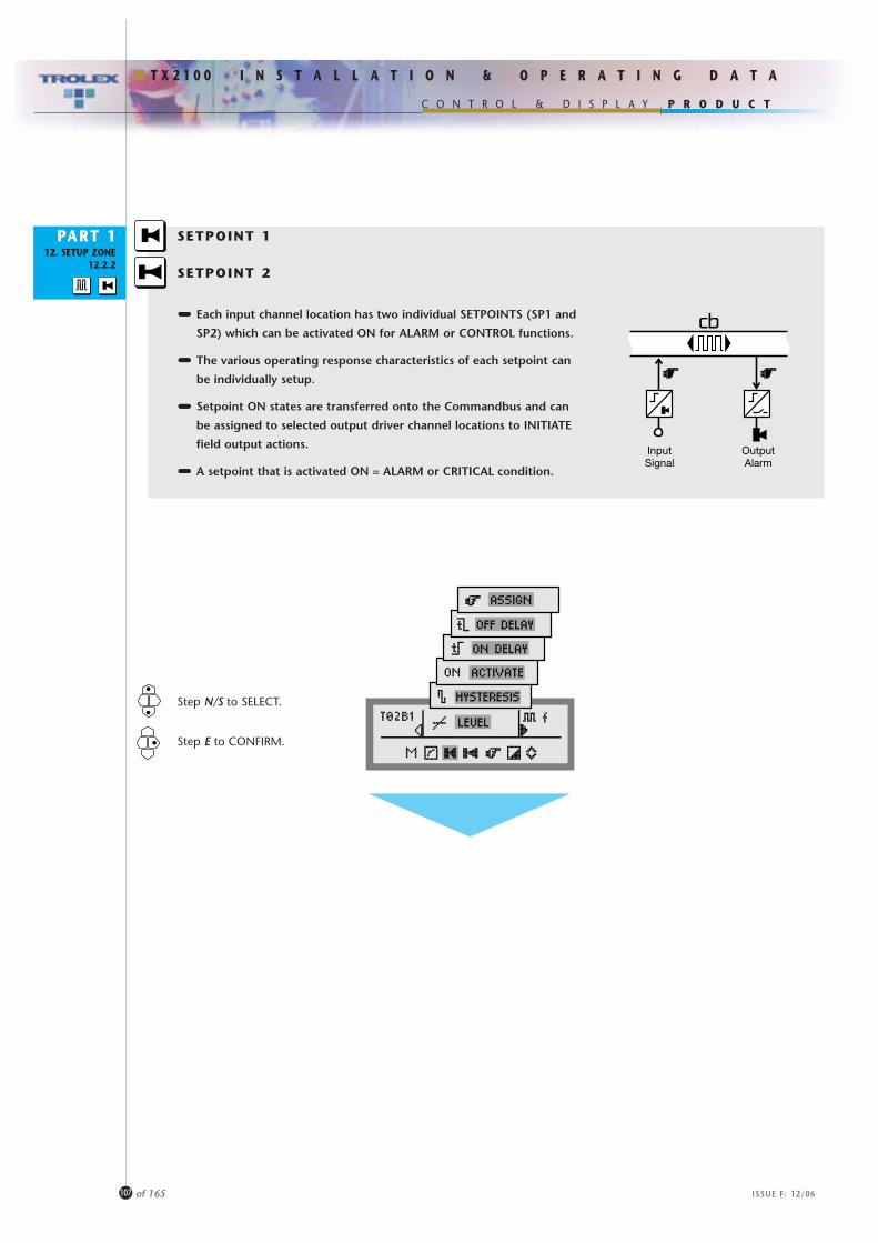
P R O D U C T
I N S T A L L A T I O N & O P E R A T I N G D A T A
C O N T R O L & D I S P L A Y
T X 2 1 0 0
PART 112. SETUP ZONE
12.2.2
107 of 165 ISSUE F: 12/06
SETPOINT 1
SETPOINT 2
••••••••••••••••••• Each input channel location has two individual SETPOINTS (SP1 and
SP2) which can be activated ON for ALARM or CONTROL functions.
••••••••••••••••••• The various operating response characteristics of each setpoint can
be individually setup.
••••••••••••••••••• Setpoint ON states are transferred onto the Commandbus and can
be assigned to selected output driver channel locations to INITIATE
field output actions.
••••••••••••••••••• A setpoint that is activated ON = ALARM or CRITICAL condition.
Step N/S to SELECT.
Step E to CONFIRM.
InputSignal
OutputAlarm
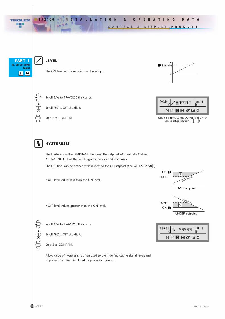
P R O D U C T
I N S T A L L A T I O N & O P E R A T I N G D A T A
C O N T R O L & D I S P L A Y
T X 2 1 0 0
PART 112. SETUP ZONE
12.2.2
108 of 165 ISSUE F: 12/06
Scroll E/W to TRAVERSE the cursor.
Scroll N/S to SET the digit.
Step E to CONFIRM.
The ON level of the setpoint can be setup.
LEVEL
Scroll E/W to TRAVERSE the cursor.
Scroll N/S to SET the digit.
Step E to CONFIRM.
The Hysteresis is the DEADBAND between the setpoint ACTIVATING ON and
ACTIVATING OFF as the input signal increases and decreases.
The OFF level can be defined with respect to the ON setpoint (Section 12.2.2 ).
• OFF level values less than the ON level.
• OFF level values greater than the ON level.
HYSTERESIS
A low value of hysteresis, is often used to override fluctuating signal levels and
to prevent 'hunting' in closed loop control systems.
0
–
+Setpoint
ON
OFFInput Signal
OVER setpoint
Range is limited to the LOWER and UPPERvalues setup (section )
OFF
ON
Input Signal
UNDER setpoint

P R O D U C T
I N S T A L L A T I O N & O P E R A T I N G D A T A
C O N T R O L & D I S P L A Y
T X 2 1 0 0
PART 112. SETUP ZONE
12.2.2
109 of 165 ISSUE F: 12/06
The setpoint can be setup to be activated ON when the input signal is OVER
the setpoint value or activated ON when the input signal is UNDER the
setpoint value.
For example; when monitoring excess speed or high frequency, the setpoint
can be set to be activated ON when the level of the input signal from the
sensor is OVER the setpoint value to give a failsafe alarm function.
Conversely, when monitoring flow failure or under speed, the setpoint can be
set to be activated ON when the input signal from the sensor is UNDER the
setpoint.
ON ACTIVATE
Step N/S to SELECT.
Step E to CONFIRM.
Both modes can be combined using the two setpoints (SP1 and SP2) toprovide boundary protection.
ON DELAY
Step E/W to TRAVERSE the digits.
Scroll N/S to SET the time t.
Step E to CONFIRM.
The activation ON of the setpoint can be delayed by an adjustable time period
(t ON). This is useful for alarm verification, to apply time delay in a process
control action, or to override a spurious fluctuation of the input signal.
The activation OFF of the setpoint can also be delayed by an adjustable time
period (t OFF).
If the input signal recedes from the setpoint level before the time has elapsed,
the timer will reset to zero, ready to start again.
Both t ON and t OFF can be Combined.
OFF DELAY
ON
ONONUNDER activate
OVER activate
OFF
ON
ON
OFF
ON
OFF
OFF ON OFF
ON
OFF
Range: 0 ... 255 seconds

P R O D U C T
I N S T A L L A T I O N & O P E R A T I N G D A T A
C O N T R O L & D I S P L A Y
T X 2 1 0 0
PART 112. SETUP ZONE
12.2.2
110 of 165 ISSUE F: 12/06
••••••••••••••••••• A SETPOINT ON state is transferred onto the Commandbus.
••••••••••••••••••• It can be SETUP to be ASSIGNED to a choice of up to 8 ONOFF/STATE
output channel card location addresses to initiate action.
••••••••••••••••••• All potential destination addresses available in the Commander system
(including the Command Module) can be sequentially presented on
the display and selected as desired.
ASSIGN
InputSignal
OutputAlarm
Scroll N/S to SELECT the address identities available.
Step E/W to TRAVERSE the address.
Scroll N/S to SET � or ✘.
Step E to CONFIRM.
ASSIGNATIONS
AssignationIdentity
ChannelAddress
Executionat the assigned
destination
�A
�:GO
✘:RESET
12T 1Destination
Address
0...30
Constant
(Terminal module)
C(The setpoint isassigned to the
Command Modulefor use in a specific
program).
Input location atthe channel
address
Single
Dual
1
1
1
2
234
QuadA latched
output relay(section
12.2.4 )

P R O D U C T
I N S T A L L A T I O N & O P E R A T I N G D A T A
C O N T R O L & D I S P L A Y
T X 2 1 0 0
PART 112. SETUP ZONE
12.2.2
111 of 165 ISSUE F: 12/06
Scroll N/S to SELECT the address identities available.
Step E/W to TRAVERSE the address.
Scroll N/S to SET � or ✘.
Step E to CONFIRM.
••••••••••••••••••• Each channel card location will give a common FAULT output state for:
• Pulse/frequency signal UNDER RANGE (section 10.2).
• Pulse/frequency signal OVER RANGE (section 10.2).
• Sensor fault.
• Channel card fault.
• OPEN CIRCUIT switch line. NAMUR inputs only (section 12.2.2 ).
• SHORT CIRCUIT switch line. NAMUR inputs only (section 12.2.2 ).
••••••••••••••••••• The FAULT state is transferred onto the Commandbus.
••••••••••••••••••• It can be SETUP to be ASSIGNED to a choice of up to 8 ONOFF/ output
channel card location addresses to initiate action.
••••••••••••••••••• All potential destination addresses available in the Commander system
(including the Command Module) can be sequentially presented on
the display and selected as desired.
ASSIGN FAULT
Fault
OutputAlarm
ASSIGNATIONS
AssignationIdentity
ChannelAddress
Executionat the assigned
destination
�A
�:GO
✘:RESET
16T 1Destination
Address
0...30
Constant
(Terminal module)
C(The setpoint isassigned to the
Command Modulefor use in a specific
program).
Input location atthe channel
address
Single
Dual
1
1
1
2
234
QuadA latched
output relay(section
12.2.4 )

P R O D U C T
I N S T A L L A T I O N & O P E R A T I N G D A T A
C O N T R O L & D I S P L A Y
T X 2 1 0 0
PART 112. SETUP ZONE
12.2.2
112 of 165 ISSUE F: 12/06
Scroll N/S to SELECT.
Step E to CONFIRM.
As a result of plant maintenance, it may be necessary to temporarily
disable a particular channel card location.
The location can be properly EXCLUDED to prevent false alarm states
occurring.
STATUS
Reinstate INCLUDE after the interruption is over.
•Always EXCLUDE a channel card location when changing a channel card otherwise the Command module will perceive a FAULT.
•Remember that where a channel card that has been first EXCLUDED and replaced, the new card will need to be SETUP, INCLUDED and REFRESHED (section 12.2.1 )

P R O D U C T
I N S T A L L A T I O N & O P E R A T I N G D A T A
C O N T R O L & D I S P L A Y
T X 2 1 0 0
PART 112. SETUP ZONE
12.2.2
113 of 165 ISSUE F: 12/06
The maximum value and minimum value that the signal has reached since last
RESET is stored.
Dangerously HIGH or LOW sensor conditions may have occurred previously
and this feature enables historic trends to be examined (section 10.2).
Stored values of previous MIN and MAX can be RESET to the current value.
MINMAX
Scroll N/S for YES/NO.
Step E to CONFIRM.
Data will be recorded in the log(section 12.1.5 and section 9).
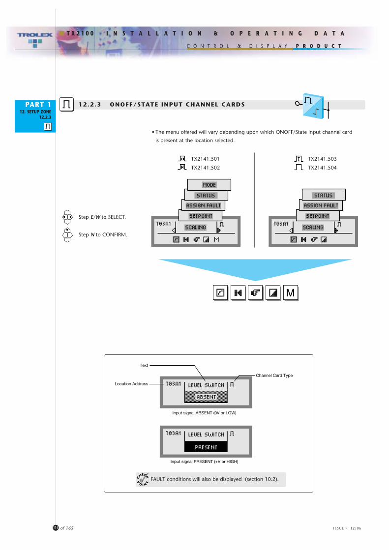
P R O D U C T
I N S T A L L A T I O N & O P E R A T I N G D A T A
C O N T R O L & D I S P L A Y
T X 2 1 0 0
PART 112. SETUP ZONE
12.2.3
114 of 165 ISSUE F: 12/06
Channel Card Type
Text
Location Address
Input signal PRESENT (+V or HIGH)
Input signal ABSENT (0V or LOW)
12.2.3 ONOFF/STATE INPUT CHANNEL CARDS
Step E/W to SELECT.
Step N to CONFIRM.
FAULT conditions will also be displayed (section 10.2).
• The menu offered will vary depending upon which ONOFF/State input channel card
is present at the location selected.
TX2141.501
TX2141.502
TX2141.503
TX2141.504

P R O D U C T
I N S T A L L A T I O N & O P E R A T I N G D A T A
C O N T R O L & D I S P L A Y
T X 2 1 0 0
PART 112. SETUP ZONE
12.2.3
115 of 165 ISSUE F: 12/06
SCALING
Step N/S to SELECT.
Step E to CONFIRM.
••••••••••••••••••• The update period and text can be determined.

P R O D U C T
I N S T A L L A T I O N & O P E R A T I N G D A T A
C O N T R O L & D I S P L A Y
T X 2 1 0 0
PART 112. SETUP ZONE
12.2.3
116 of 165 ISSUE F: 12/06
Step E/W to traverse the cursor.
Scroll N/S to SET the value.
Step E to CONFIRM.
The INPUT STATE is sampled at pre-determined intervals and the update time
period is adjustable.
A low setting will give rapid reaction to the input signal and higher settings
may be entered as a means of applying a delay to the input.
UPDATE
Step E/W to TRAVERSE the characters.
Scroll N/S to SET the characters.
Step E to CONFIRM.
Duty Text can be entered to denote the Input duty, the location or the
tag reference of the input device.
Up to 12 digits of text can be entered into the display and there is a
menu of Letters, Numbers and Symbols to choose from.
TEXT
Update
Range: 0.1 ... 60 seconds
A default message will appear if no user text is entered.
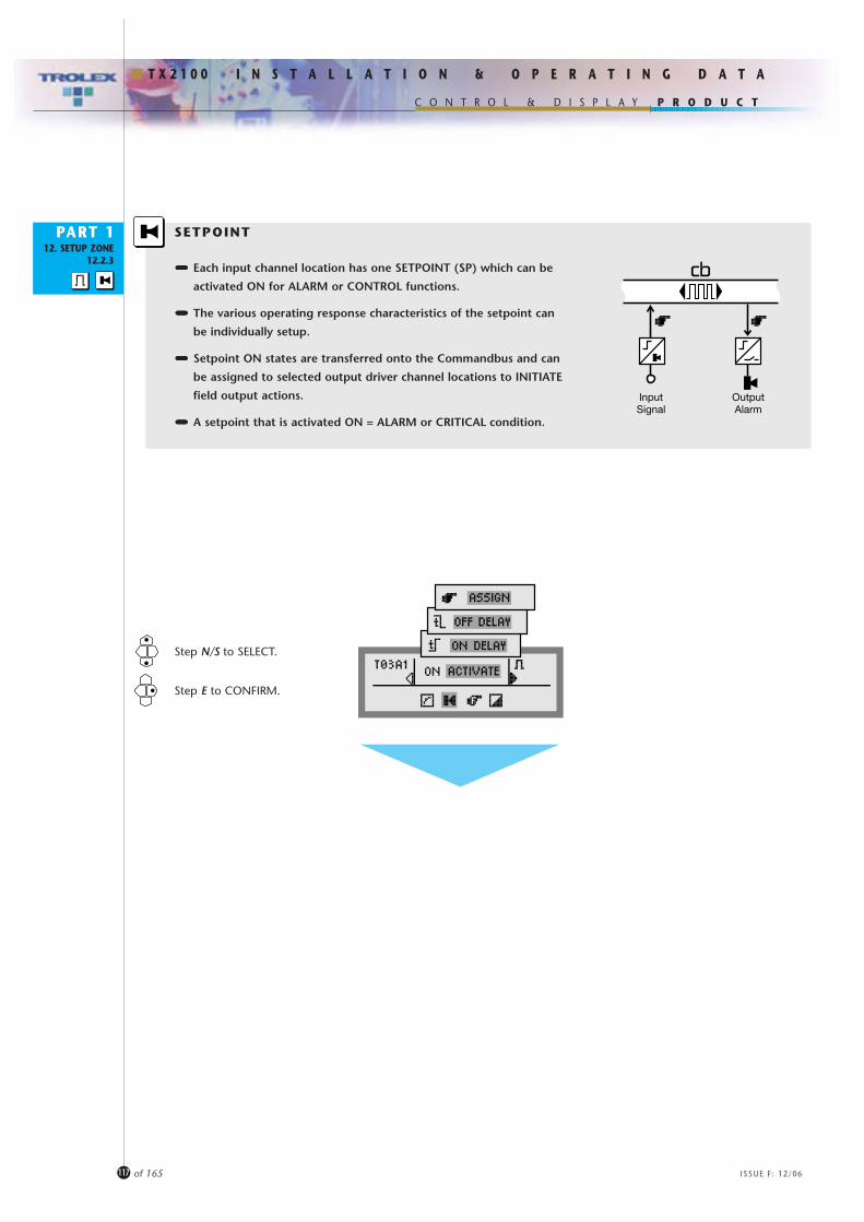
P R O D U C T
I N S T A L L A T I O N & O P E R A T I N G D A T A
C O N T R O L & D I S P L A Y
T X 2 1 0 0
PART 112. SETUP ZONE
12.2.3
117 of 165 ISSUE F: 12/06
SETPOINT
••••••••••••••••••• Each input channel location has one SETPOINT (SP) which can be
activated ON for ALARM or CONTROL functions.
••••••••••••••••••• The various operating response characteristics of the setpoint can
be individually setup.
••••••••••••••••••• Setpoint ON states are transferred onto the Commandbus and can
be assigned to selected output driver channel locations to INITIATE
field output actions.
••••••••••••••••••• A setpoint that is activated ON = ALARM or CRITICAL condition.
Step N/S to SELECT.
Step E to CONFIRM.
InputSignal
OutputAlarm

P R O D U C T
I N S T A L L A T I O N & O P E R A T I N G D A T A
C O N T R O L & D I S P L A Y
T X 2 1 0 0
PART 112. SETUP ZONE
12.2.3
118 of 165 ISSUE F: 12/06
The setpoint can be setup to be activated ON when the input signal is
PRESENT or activated ON when the input signal is ABSENT.
ON ACTIVATE
Step N/S to SELECT.
Step E to CONFIRM.
ON DELAY
Scroll N/S to SET the time t.
Step E to CONFIRM.
The activation ON of the setpoint can be delayed by an adjustable time period
(t ON). This is useful for alarm verification, to apply time delay in a process
control action, or to override a spurious fluctuation of the input signal.
The activation OFF of the setpoint can also be delayed by an adjustable time
period (t OFF).
If the setpoint goes to OFF before the time has elapsed, the timer will reset to
zero, ready to start again.
OFF DELAY
Both t ON and t OFF can be Combined.
OFF
ON
ON
OFF
ON
OFF
OFF ON OFF
ON
OFF
ON
ONABSENT activate.........
PRESENT activate.......
Input Signal State: Absent
Present
Range: 0 ... 255 seconds
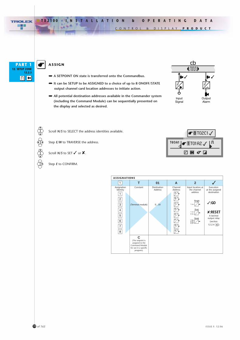
P R O D U C T
I N S T A L L A T I O N & O P E R A T I N G D A T A
C O N T R O L & D I S P L A Y
T X 2 1 0 0
PART 112. SETUP ZONE
12.2.3
119 of 165 ISSUE F: 12/06
Scroll N/S to SELECT the address identities available.
Step E/W to TRAVERSE the address.
Scroll N/S to SET � or ✘.
Step E to CONFIRM.
••••••••••••••••••• A SETPOINT ON state is transferred onto the Commandbus.
••••••••••••••••••• It can be SETUP to be ASSIGNED to a choice of up to 8 ONOFF/STATE
output channel card location addresses to initiate action.
••••••••••••••••••• All potential destination addresses available in the Commander system
(including the Command Module) can be sequentially presented on
the display and selected as desired.
ASSIGN
��
InputSignal
OutputAlarm
ASSIGNATIONS
AssignationIdentity
ChannelAddress
Executionat the assigned
destination
�A
�:GO
✘:RESET
01T 2Destination
Address
0...30
Constant
(Terminal module)
C(The setpoint isassigned to the
Command Modulefor use in a specific
program).
Input location atthe channel
address
Single
Dual
1
1
1
2
234
QuadA latched
output relay(section
12.2.4 )
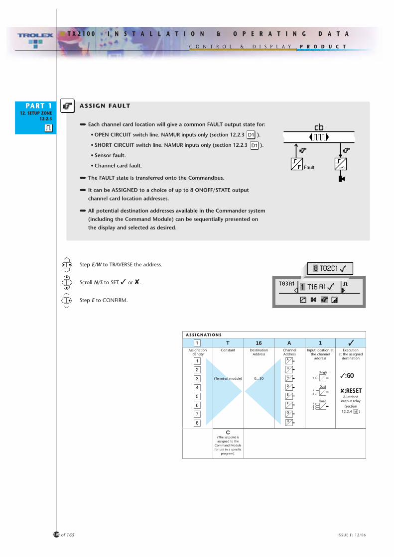
P R O D U C T
I N S T A L L A T I O N & O P E R A T I N G D A T A
C O N T R O L & D I S P L A Y
T X 2 1 0 0
PART 112. SETUP ZONE
12.2.3
120 of 165 ISSUE F: 12/06
••••••••••••••••••• Each channel card location will give a common FAULT output state for:
• OPEN CIRCUIT switch line. NAMUR inputs only (section 12.2.3 ).
• SHORT CIRCUIT switch line. NAMUR inputs only (section 12.2.3 ).
• Sensor fault.
• Channel card fault.
••••••••••••••••••• The FAULT state is transferred onto the Commandbus.
••••••••••••••••••• It can be ASSIGNED to a choice of up to 8 ONOFF/STATE output
channel card location addresses.
••••••••••••••••••• All potential destination addresses available in the Commander system
(including the Command Module) can be sequentially presented on
the display and selected as desired.
ASSIGN FAULT
Fault
Step E/W to TRAVERSE the address.
Scroll N/S to SET � or ✘.
Step E to CONFIRM.
ASSIGNATIONS
AssignationIdentity
ChannelAddress
Executionat the assigned
destination
�A
�:GO
✘:RESET
16T 1Destination
Address
0...30
Constant
(Terminal module)
C(The setpoint isassigned to the
Command Modulefor use in a specific
program).
Input location atthe channel
address
Single
Dual
1
1
1
2
234
QuadA latched
output relay(section
12.2.4 )

P R O D U C T
I N S T A L L A T I O N & O P E R A T I N G D A T A
C O N T R O L & D I S P L A Y
T X 2 1 0 0
PART 112. SETUP ZONE
12.2.3
121 of 165 ISSUE F: 12/06
Scroll E/W to SELECT.
Step S to CONFIRM.
As a result of plant maintenance, it may be necessary to temporarily
disable a particular channel card location.
The location can be properly EXCLUDED to prevent false alarm states
occurring.
STATUS
Reinstate INCLUDE after the interruption is over.
•Always EXCLUDE a channel card location when changing a channel card otherwise the Command module will perceive a FAULT.
•Remember that where a channel card that has been first EXCLUDED and replaced, the new card will need to be SETUP, INCLUDED and REFRESHED (section 12.2.3 )
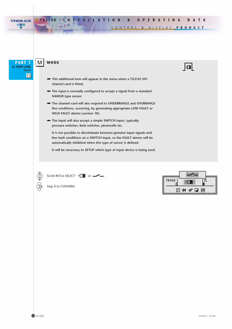
Scroll N/S to SELECT or .
Step E to CONFIRM.
P R O D U C T
I N S T A L L A T I O N & O P E R A T I N G D A T A
C O N T R O L & D I S P L A Y
T X 2 1 0 0
PART 1
122 of 165 ISSUE F: 12/06
MODE12. SETUP ZONE
12.2.3
••••••••••••••••••• This additional item will appear in the menu when a TX2141.501
channel card is fitted.
••••••••••••••••••• The input is normally configured to accept a signal from a standard
NAMUR type sensor.
••••••••••••••••••• The channel card will also respond to UNDERRANGE and OVERRANGE
line conditions, occurring, by generating appropriate LOW FAULT or
HIGH FAULT alarms (section 10).
••••••••••••••••••• The input will also accept a simple SWITCH input, typically;
pressure switches, limit switches, photocells etc.
It is not possible to discriminate between genuine input signals and
line fault conditions on a SWITCH input, so the FAULT alarms will be
automatically inhibited when this type of sensor is defined.
It will be necessary to SETUP which type of input device is being used.

Scroll N/S to SELECT or .
Step E to CONFIRM.
PART 1 MODE12. SETUP ZONE
12.2.3
••••••••••••••••••• This additional item will appear in the menu when a TX2141.502
channel card is fitted.
••••••••••••••••••• The input is configured to accept an input from switching devices such
as pressure switches, limit switches and thermostats, etc. with a diode
connected in SERIES at the remote point.
••••••••••••••••••• The channel card will also respond to a SHORT-CIRCUIT condition,
occurring, by generating a HIGH FAULT alarm (section 10).
••••••••••••••••••• Also connect a shunt resistor in PARALLEL with the switching device at
the remote point and the channel card will also be able to
DISCRIMINATE between a normal contact opening function and an
OPEN-CIRCUIT line condition. An OPEN-CIRCUIT condition will generate
a LOW FAULT alarm (section 10).
••••••••••••••••••• It will be necessary to SETUP the fact that a shunt resistor is being used.
P R O D U C T
I N S T A L L A T I O N & O P E R A T I N G D A T A
C O N T R O L & D I S P L A Y
T X 2 1 0 0
123 of 165 ISSUE F: 12/06
D
D
R
D = IN4001 or similar
D = IN4001 or similarR = 10K ohms
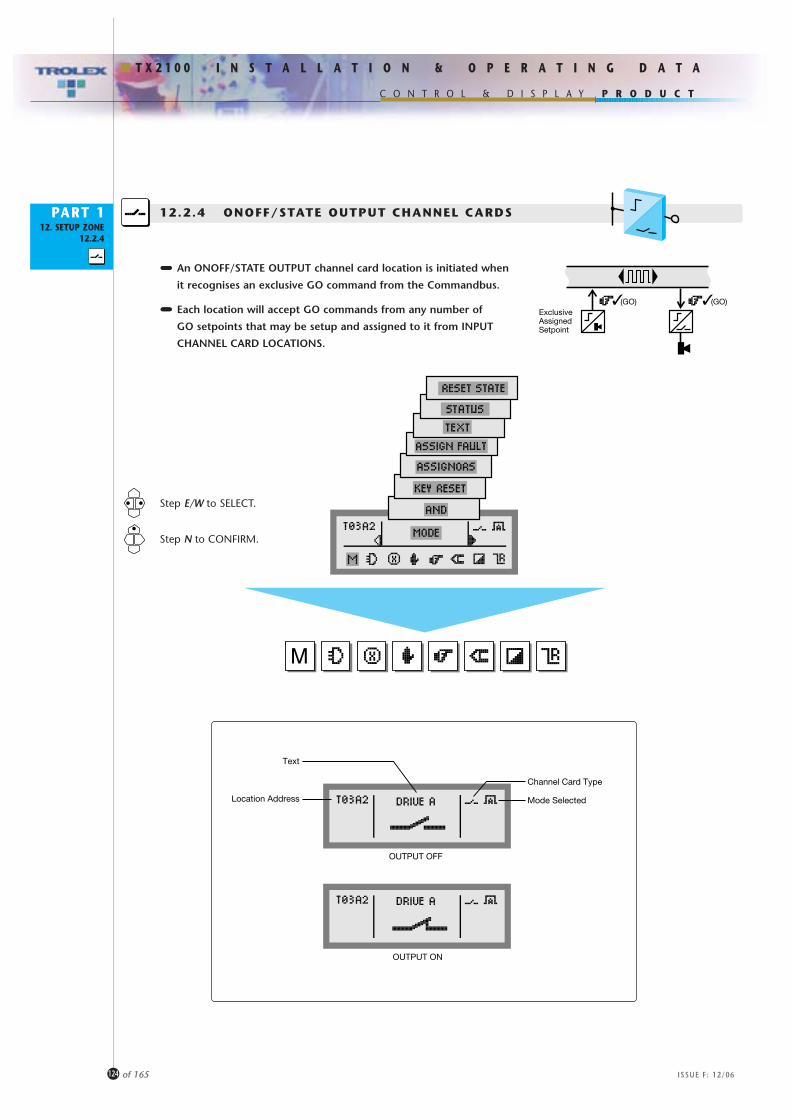
P R O D U C T
I N S T A L L A T I O N & O P E R A T I N G D A T A
C O N T R O L & D I S P L A Y
T X 2 1 0 0
PART 112. SETUP ZONE
12.2.4
124 of 165 ISSUE F: 12/06
12.2.4 ONOFF/STATE OUTPUT CHANNEL CARDS
Step E/W to SELECT.
Step N to CONFIRM.
••••••••••••••••••• An ONOFF/STATE OUTPUT channel card location is initiated when
it recognises an exclusive GO command from the Commandbus.
••••••••••••••••••• Each location will accept GO commands from any number of
GO setpoints that may be setup and assigned to it from INPUT
CHANNEL CARD LOCATIONS.
(GO) (GO)ExclusiveAssignedSetpoint
��
Channel Card Type
Mode Selected
Text
Location Address
OUTPUT OFF
OUTPUT ON

P R O D U C T
I N S T A L L A T I O N & O P E R A T I N G D A T A
C O N T R O L & D I S P L A Y
T X 2 1 0 0
PART 112. SETUP ZONE
12.2.4
125 of 165 ISSUE F: 12/06
Scroll N/S to SELECT.
Step E to CONFIRM.
••••••••••••••••••• The output operating MODE can be setup.
MODE
••••••••••••••••••• The channel will ACTIVATE when the GO command is PRESENT and
RESET when the GO command is ABSENT.
AUTO RESET
••••••••••••••••••• The channel will ACTIVATE when the GO command is PRESENT and
LATCH until RESET.
LATCH
• Each location will accept RESET commands from any number of RESET setpoints that may be setup and assigned to it from INPUT CHANNEL CARD LOCATIONS.
• A LATCHED output switch can also be reset from the Command module keypad (section 12.2.4 ).
••••••••••••••••••• The channel will ACTIVATE when the GO command appears and
RESET after an adjustable time.
PULSE
(RESET) (GO)
Input
�✘ (RESET)✘
GOCOMMAND
ACTIVATE ACTIVATEOUTPUT
GOCOMMAND
ACTIVATEOUTPUT
GOCOMMAND
ACTIVATEOUTPUT
X
Step E/W to TRAVERSE the digits.
Scroll N/S to SET the time ‘t’.
Step E to CONFIRM.Range: 0.1 ... 25 seconds
t
The RESET STATE of the output switching device can also be selected for the preferred failsafe condition(section 12.2.4 )
• Output circuit closed (ON) when RESET or• Output circuit open (OFF) when RESET.
For failsafe reasons, the standard contact format is wired NORMALLY OPEN when the relay is de-energised.Contacts can be supplied wired NORMALLY CLOSED to specification, for alternative failsafe operation.

P R O D U C T
I N S T A L L A T I O N & O P E R A T I N G D A T A
C O N T R O L & D I S P L A Y
T X 2 1 0 0
PART 112. SETUP ZONE
12.2.4
126 of 165 ISSUE F: 12/06
Scroll N/S to SET the number of GO commands
required to initiate the output function.
Step E to CONFIRM.
The output function can be set to initiate ONLY when several GO
commands are present at the SAME TIME.
AND
VOTING INPUTS
This mode can also be used for VOTING inputs eg:
If GO commands are assigned to the output channel card location
from say 4 other input channel cards, set the AND at 2.
The output will activate on a VOTE of any 2 out of 4. 2
InputInputInputInput
(GO)�(GO)� (GO)� (GO)� (GO)�
Range: 1 ... 10 simultaneous GO commands
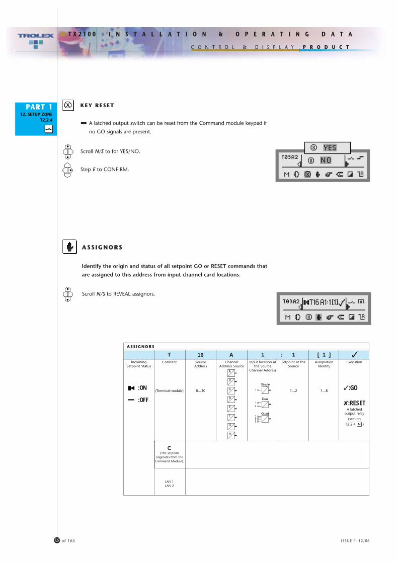
P R O D U C T
I N S T A L L A T I O N & O P E R A T I N G D A T A
C O N T R O L & D I S P L A Y
T X 2 1 0 0
PART 112. SETUP ZONE
12.2.4
127 of 165 ISSUE F: 12/06
Scroll N/S to REVEAL assignors.
Identify the origin and status of all setpoint GO or RESET commands that
are assigned to this address from input channel card locations.
ASSIGNORS
••••••••••••••••••• A latched output switch can be reset from the Command module keypad if
no GO signals are present.
KEY RESETX
Scroll N/S to for YES/NO.
Step E to CONFIRM.
ASSIGNORS
IncomingSetpoint Status
ChannelAddress Source
Execution
�:GO
✘:RESET
SourceAddress
0...30
Constant
(Terminal module)
C(The setpoint
originates from theCommand Module).
LAN 1LAN 2
Input location atthe Source
Channel Address
Single
Dual
1
1
1
2
234
Quad
:ON
:OFFA latched
output relay(section
12.2.4 )
Setpoint at theSource
1...2
AssignationIdentity
1...8
�A16T 1 : 1 [ 1 ]
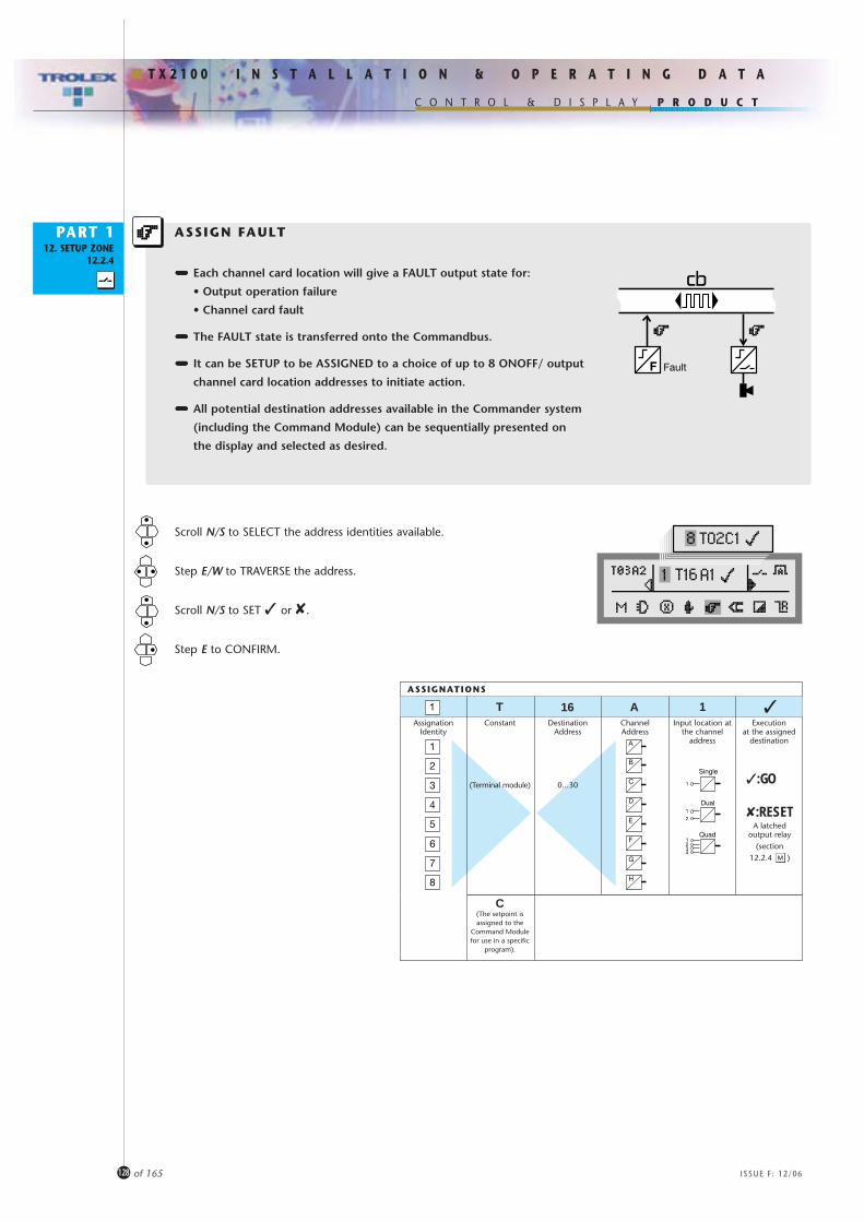
P R O D U C T
I N S T A L L A T I O N & O P E R A T I N G D A T A
C O N T R O L & D I S P L A Y
T X 2 1 0 0
PART 112. SETUP ZONE
12.2.4
128 of 165 ISSUE F: 12/06
Scroll N/S to SELECT the address identities available.
Step E/W to TRAVERSE the address.
Scroll N/S to SET � or ✘.
Step E to CONFIRM.
••••••••••••••••••• Each channel card location will give a FAULT output state for:
• Output operation failure
• Channel card fault
••••••••••••••••••• The FAULT state is transferred onto the Commandbus.
••••••••••••••••••• It can be SETUP to be ASSIGNED to a choice of up to 8 ONOFF/ output
channel card location addresses to initiate action.
••••••••••••••••••• All potential destination addresses available in the Commander system
(including the Command Module) can be sequentially presented on
the display and selected as desired.
ASSIGN FAULT
Fault
ASSIGNATIONS
AssignationIdentity
ChannelAddress
Executionat the assigned
destination
�A
�:GO
✘:RESET
16T 1Destination
Address
0...30
Constant
(Terminal module)
C(The setpoint isassigned to the
Command Modulefor use in a specific
program).
Input location atthe channel
address
Single
Dual
1
1
1
2
234
QuadA latched
output relay(section
12.2.4 )

P R O D U C T
I N S T A L L A T I O N & O P E R A T I N G D A T A
C O N T R O L & D I S P L A Y
T X 2 1 0 0
PART 112. SETUP ZONE
12.2.4
129 of 165 ISSUE F: 12/06
Step E/W to TRAVERSE the characters.
Scroll N/S to SET the characters.
Step E to CONFIRM.
Duty Text can be entered to denote the Input duty, the location or the tag reference of the input device.
Up to 12 digits of text can be entered into the display and there is a menu of Letters, Numbers and Symbols to
choose from.
TEXT
Scroll N/S to SELECT.
Step E to CONFIRM.
The channel will ACTIVATE and RESET in response to commands from the Commandbus.
••••••••••••••••••• For normal, failsafe alarm functions, the RESET STATE may be selected
for: OUTPUT CIRCUIT CLOSED (ON).
••••••••••••••••••• When the signal is being used to start drives, or to initiate machine
functions, the RESET STATE may be selected for: OUTPUT CIRCUIT OPEN (OFF).
RESET STATE
A default message will appear if no user text is entered.
Scroll E/W to SELECT.
Step S to CONFIRM.
As a result of plant maintenance, it may be necessary to temporarily disable a particular channel card location.
The location can be properly EXCLUDED to prevent false alarm states occurring.
STATUS
Reinstate INCLUDE after the interruption is over.
•Always EXCLUDE a channel card location when changing a channel card otherwise the Command module will perceive a FAULT.
•Remember that where a channel card that has been EXCLUDED and replaced, the new card will need to be first SETUP, INCLUDED and REFRESHED (section 12.2.3 )

P R O D U C T
I N S T A L L A T I O N & O P E R A T I N G D A T A
C O N T R O L & D I S P L A Y
T X 2 1 0 0
PART 112. SETUP ZONE
12.2.5
130 of 165 ISSUE F: 12/06
12.2.5 ANALOGUE OUTPUT CHANNEL CARD
Step E/W to SELECT.
Step N to CONFIRM.
••••••••••••••••••• Analogue output for driving motorised valve positioners, servo
devices, process signal loops, invertors, recorders, speed controllers
and heat controllers.
••••••••••••••••••• Output signal standard: 4...20mA.
••••••••••••••••••• The analogue output signal value can be controlled by any selected
analogue or pulse/frequency input channel card location source as a
signal repeater.
••••••••••••••••••• The analogue output signal value can be controlled by programme data
codes sourced from one of the LAN inputs on the Command module.
Selected Analogue orFrequency Input
Channel Card Location Analogue Output
Channel Card Type
Text
Location Address
Signal
Units
Upper Scale
Decimal Point
Signal Bargraph
Lower Scale

P R O D U C T
I N S T A L L A T I O N & O P E R A T I N G D A T A
C O N T R O L & D I S P L A Y
T X 2 1 0 0
PART 112. SETUP ZONE
12.2.5
131 of 165 ISSUE F: 12/06
SOURCE
••••••••••••••••••• The analogue output signal value can be determined from three
optional control sources:
1. The analogue input signal value generated by any selected input
location on a channel card.
2. LAN 1 / LAN 2.
2. Data codes generated by values that are programmed into the
command module when special control function software is
installed in the Command module (section 13).
••••••••••••••••••• All potential source addresses available in the Commander system
(including the Command Module) can be sequentially presented on
the display and selected as desired.
Analogue orFrequency Input
Channel Card Location Analogue Output
SOURCECODE
SOURCECODE
Analogue Output
COMMANDMODULE
(PLC)
SOURCECODE
SOURCECODE
Scroll N/S to SELECT a channel card source or a LAN source.
Step E to CONFIRM.
Scroll N/S to SELECT the address identity available.
Step E to CONFIRM. CHANNEL CARD SOURCE
ChannelAddress
A16T 1SourceAddress
0...30
Constant
(Terminal module)
Input location atthe Channel
Address
Single
Dual
1
1
1
2
234
Quad
LAN 1
LAN 2
LAN1,2
LAN SOURCE

P R O D U C T
I N S T A L L A T I O N & O P E R A T I N G D A T A
C O N T R O L & D I S P L A Y
T X 2 1 0 0
PART 112. SETUP ZONE
12.2.5
132 of 165 ISSUE F: 12/06
OFFSET ZERO
Scroll N/S to change the analogue output signal until it complies with the
requirement of the field device.
Step E to CONFIRM.
••••••••••••••••••• The value of the ZERO point can be OFFSET to match the characteristics
of the field device.
••••••••••••••••••• The value of an analogue output level or GAIN can be OFFSET to match
the characteristics of the field device and to compensate for any line
losses.
OFFSET GAIN
• Both OFFSET ZERO and OFFSET GAIN may be applied to an output signal.
• The output signal will assume linearity between OFFSETS that are CONFIRMED.
• OFFSET or GAIN adjustment may be extrapolated to an intermediate value of an analogue output signal.
OFFSET GAIN
OFFSET ZERO
ZERO
+20mA
GAIN
+20mA
Range: ±10%

P R O D U C T
I N S T A L L A T I O N & O P E R A T I N G D A T A
C O N T R O L & D I S P L A Y
T X 2 1 0 0
PART 112. SETUP ZONE
12.2.5
133 of 165 ISSUE F: 12/06
Scroll N/S to SELECT the address identities available.
Step E/W to TRAVERSE the address.
Scroll N/S to SET � or ✘.
Step E to CONFIRM.
••••••••••••••••••• Each channel card location will give a common FAULT output state for:
• Analogue output signal UNDER RANGE (section 10.2).
• Analogue output signal OVER RANGE (section 10.2).
• Channel card fault.
••••••••••••••••••• The FAULT state is transferred onto the Commandbus.
••••••••••••••••••• It can be SETUP to be ASSIGNED to a choice of up to 8 ONOFF/ output
channel card location addresses to initiate action.
••••••••••••••••••• All potential destination addresses available in the Commander system
(including the Command Module) can be sequentially presented on
the display and selected as desired.
ASSIGN FAULT
Fault
ASSIGNATIONS
AssignationIdentity
ChannelAddress
Executionat the assigned
destination
�A
�:GO
✘:RESET
16T 1Destination
Address
0...30
Constant
(Terminal module)
C(The setpoint isassigned to the
Command Modulefor use in a specific
program).
Input location atthe channel
address
Single
Dual
1
1
1
2
234
QuadA latched
output relay(section
12.2.4 )

P R O D U C T
I N S T A L L A T I O N & O P E R A T I N G D A T A
C O N T R O L & D I S P L A Y
T X 2 1 0 0
PART 112. SETUP ZONE
12.2.5
134 of 165 ISSUE F: 12/06
Step E/W to TRAVERSE the characters.
Scroll N/S to SET the characters.
Step E to CONFIRM.
Duty Text can be entered to denote the Input duty, the location or the
tag reference of the input device.
Up to 12 digits of text can be entered into the display and there is a
menu of Letters, Numbers and Symbols to choose from.
TEXT
A default message will appear if no user text is entered.

P R O D U C T
I N S T A L L A T I O N & O P E R A T I N G D A T A
C O N T R O L & D I S P L A Y
T X 2 1 0 0
PART 112. SETUP ZONE
12.2.5
135 of 165 ISSUE F: 12/06
Scroll N/S to SELECT.
Step E to CONFIRM.
As a result of plant maintenance, it may be necessary to temporarily
disable a particular channel card location.
The location can be properly EXCLUDED to prevent false alarm states
occurring.
STATUS
Reinstate INCLUDE after the interruption is over.
•Always EXCLUDE a channel card location when changing a channel card otherwise the Command module will perceive a FAULT.
•Remember that where a channel card that has been first EXCLUDED and replaced, the new card will need to be SETUP, INCLUDED and REFRESHED (section 12.2.3 )

P R O D U C T
I N S T A L L A T I O N & O P E R A T I N G D A T A
C O N T R O L & D I S P L A Y
T X 2 1 0 0
PART 112. SETUP ZONE
12.2.5
136 of 165 ISSUE F: 12/06
Scroll N/S for YES/NO.
Step E to CONFIRM.
The maximum value and minimum value that the output signal has reached
since the last RESET is stored.
Stored values of previous MIN and MAX can be RESET to the current value.
MINMAX
Data will also be recorded in the Log (section 12.1.5 and section 9).

P R O D U C T
I N S T A L L A T I O N & O P E R A T I N G D A T A
C O N T R O L & D I S P L A Y
T X 2 1 0 0
PART 113. SPECIAL
CONTROL ANDMONITORING
FUNCTIONS
137 of 165 ISSUE F: 12/06
13 special control
and monitoring
funct ions

ISSUE F: 12/06138 of 165
P R O D U C T
I N S T A L L A T I O N & O P E R A T I N G D A T A
C O N T R O L & D I S P L A Y
T X 2 1 0 0
•••••••••••••• The standard Command module is equipped with a processor program that
provides the alarm configuration routines described in section 12, enabling
elementary monitoring and shutdown functions to be programmed by the user
directly through the keypad.
••••••••••••••• Special function routines or system upgrades can also be installed into the
Command module for control programs & function blocks of greater complexity.
The program is installed through the LAN 1 data connecting terminals or the
LAN 2 data plug-in connector (section 2.1).
The complete Commander setup can also be installed into
the Command module through the LAN 1 or LAN 2 data ports,
using a standard PC programming tool (section 2).
The standard communication protocol is MODBUS and it is
provided with the system in CD format. An RS485/RS232
connector will be required for the PC data port.
Please contact our technical sales department for details.
TX2199: Commander Configuration Software Package.
PART 113. SPECIAL
CONTROL ANDMONITORING
FUNCTIONS

ISSUE F: 12/06139 of 165
P R O D U C T
I N S T A L L A T I O N & O P E R A T I N G D A T A
C O N T R O L & D I S P L A Y
T X 2 1 0 0
14 adding an
operator inter face
or PC
PART 114. ADDING AN
OPERATORINTERFACE OR PC
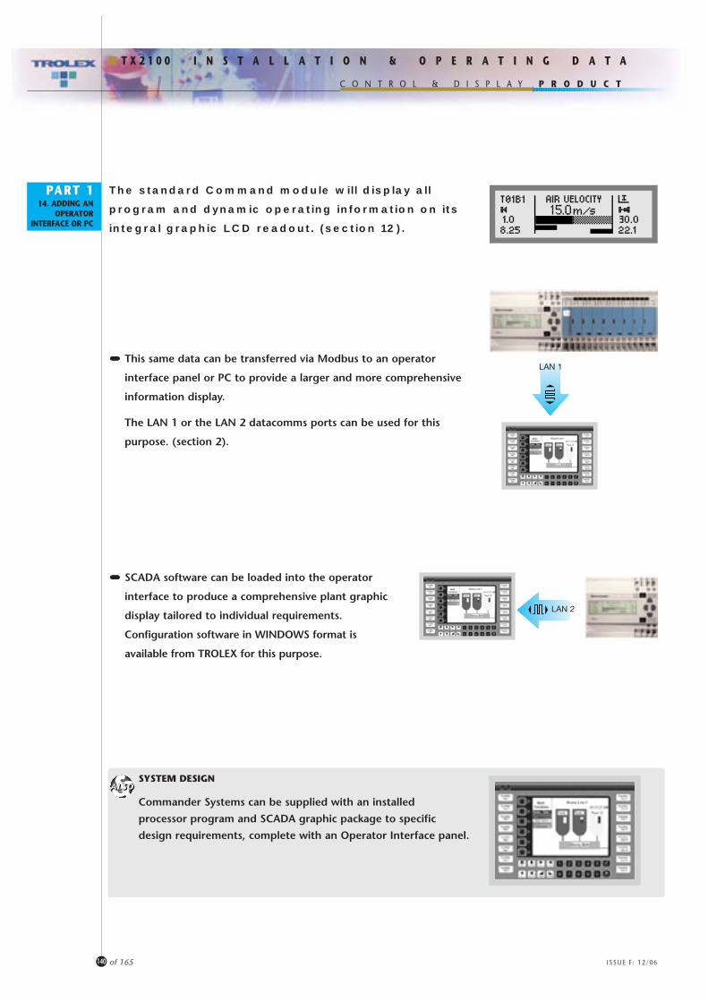
P R O D U C T
I N S T A L L A T I O N & O P E R A T I N G D A T A
C O N T R O L & D I S P L A Y
T X 2 1 0 0
PART 114. ADDING AN
OPERATORINTERFACE OR PC
140 of 165 ISSUE F: 12/06
SYSTEM DESIGN
Commander Systems can be supplied with an installed
processor program and SCADA graphic package to specific
design requirements, complete with an Operator Interface panel.
The standard Command module will display all
program and dynamic operating information on its
integral graphic LCD readout. (section 12).
••••••••••••••• This same data can be transferred via Modbus to an operator
interface panel or PC to provide a larger and more comprehensive
information display.
The LAN 1 or the LAN 2 datacomms ports can be used for this
purpose. (section 2).
••••••••••••••• SCADA software can be loaded into the operator
interface to produce a comprehensive plant graphic
display tailored to individual requirements.
Configuration software in WINDOWS format is
available from TROLEX for this purpose.
LAN 2
LAN 1
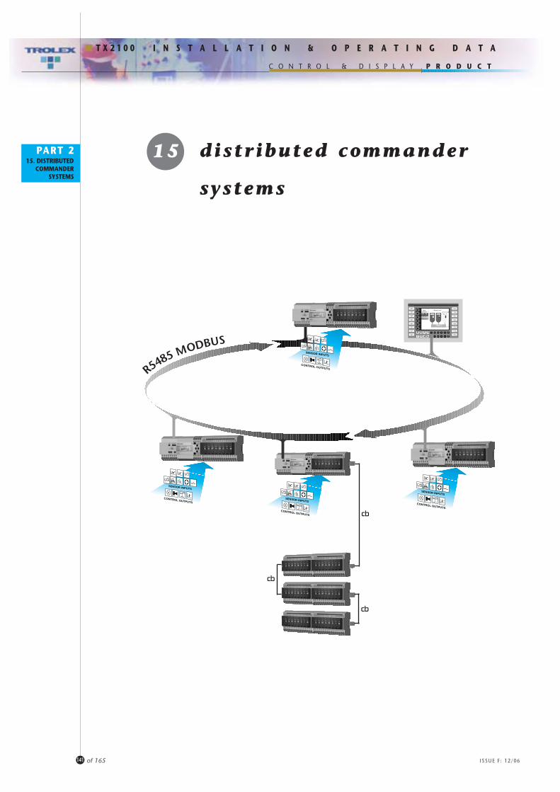
15 distr ibuted commander
systems
P R O D U C T
141
I N S T A L L A T I O N & O P E R A T I N G D A T A
C O N T R O L & D I S P L A Y
of 165
T X 2 1 0 0
PART 215. DISTRIBUTED
COMMANDERSYSTEMS
ISSUE F: 12/06
SENSOR INPUTS
CONTROL OUTPUTS
SENSOR INPUTS
CONTROL OUTPUTS
SENSOR INPUTS
CONTROL OUTPUTS
R5485 MODBUSSENSOR INPUTS
CONTROL OUTPUTS

Additional technical data for the
application of Commander in distributed
monitoring and control systems is
available in the Trolex publication
P R O D U C T
142
I N S T A L L A T I O N & O P E R A T I N G D A T A
C O N T R O L & D I S P L A Y
of 165
T X 2 1 0 0
PART 215. DISTRIBUTED
COMMANDERSYSTEMS
ISSUE F: 12/06
Distributed individual commander systems can becombined on a data network to communicate data to amaster PC or central control room.
15.1 DATA COMMUNICATIONS
All functional data accumulated by the Command module is available from both the LAN 1 and LAN 2 output ports of the command module in the form of multidrop RS485 datacomms(section 2). This will support MODBUS protocol and up to30 Commander stations can be combined on the databusover a total distance of about 1000 metres.In practice the communications capability is influenced by the type of cable used and the system architecture - our Commandersystem applications engineers can provide technical assessment ofindividual installation designs.
Protocol characteristics of the LAN 1 and LAN 2 datacomms outputsare fully menu selectable (section 12).
RS485
1000 metres
(and/or 30 Commander Stations)
RS485 Databus
Additional technical data for the application of
Commander in distributed monitoring and
control systems is available
in the Trolex publication
'COMMUNICATION WITH COMMANDER'

PART 3ASSEMBLING
SYSTEMS a s s e m b l i n gs y s t e m s
P R O D U C T
143
I N S T A L L A T I O N & O P E R A T I N G D A T A
C O N T R O L & D I S P L A Y
of 165
T X 2 1 0 0
ISSUE F: 12/06
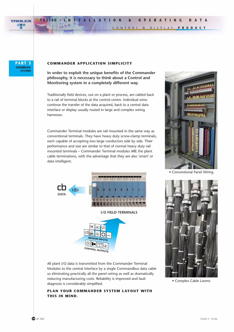
PART 3ASSEMBLING
SYSTEMS
COMMANDER APPLICATION SIMPLICITY
In order to exploit the unique benefits of the Commanderphilosophy, it is necessary to think about a Control andMonitoring system in a completely different way.
Traditionally field devices, out on a plant or process, are cabled backto a rail of terminal blocks at the control centre. Individual wirescontinue the transfer of the data acquired, back to a central datainterface or display usually routed in large and complex wiringharnesses.
Commander Terminal modules are rail mounted in the same way asconventional terminals. They have heavy duty screw-clamp terminals,each capable of accepting two large conductors side by side. Theirperformance and size are similar to that of normal heavy duty railmounted terminals – Commander Terminal modules ARE the plantcable terminations, with the advantage that they are also 'smart' ordata intelligent.
All plant I/O data is transmitted from the Commander TerminalModules to the central interface by a single Commandbus data cableso eliminating practically all the panel wiring as well as dramaticallyreducing manufacturing costs. Reliability is improved and faultdiagnosis is considerably simplified.
PLAN YOUR COMMANDER SYSTEM LAYOUT WITHTHIS IN MIND.
SENSOR INPUTS
CONTROL OUTPUTS
I/O FIELD TERMINALS
DATA
• Conventional Panel Wiring
• Complex Cable Looms
P R O D U C T
144
I N S T A L L A T I O N & O P E R A T I N G D A T A
C O N T R O L & D I S P L A Y
of 165
T X 2 1 0 0
ISSUE F: 12/06

PART 3ASSEMBLING
SYSTEMS
Terminal cubicles using Commander Terminal Modules can belocated at the optimum position to marshal incoming plant cables.Data from the terminal modules is then transferred via a singleCommandbus cable to the control area or display device – no plantcables need enter the control and monitoring centre.
This principle can be maximised even further – the Commandbus canextend out into the plant and connect to a Terminal Moduledispersed at a convenient location, collecting I/O data from groups ofsensors or commanding control devices. Complex and expensivecable runs can be eliminated.
FIELD I/O
P R O D U C T
145
I N S T A L L A T I O N & O P E R A T I N G D A T A
C O N T R O L & D I S P L A Y
of 165
T X 2 1 0 0
ISSUE F: 12/06

PART 3ASSEMBLING
SYSTEMS
COMMANDER DESIGN VERSATILITY
Whether the installation is a few sensors and control devicesmonitoring a small machine or a major distributed processmonitoring project, the same Commander system can deal with it.Furthermore, a Commander system design does not need to be'committed' at an early stage in the project. Once the Commanderback-bone is in place, the format can be adapted or changed to suitthe design requirements of the plant as it develops. Systemconfiguration can be modified as required, sensor and control devicefunctions can be individually programmed and control/alarmfunctions can be decided during final commissioning. The sameversatility can be exploited for later plant upgrades and changes.
Install a standard software package or a PLC database into theCommand Module and highly complex control and monitoringfunctions can be executed.
SENSOR INPUTS
CONTROL OUTPUTS
SENSOR INPUTS
CONTROL OUTPUTS
SENSOR INPUTS
CONTROL OUTPUTS
SENSOR INPUTS
CONTROL OUTPUTS
P R O D U C T
146
I N S T A L L A T I O N & O P E R A T I N G D A T A
C O N T R O L & D I S P L A Y
of 165
T X 2 1 0 0
ISSUE F: 12/06

PART 317. SYSTEMPLANNING
17 system planning
P R O D U C T
147
I N S T A L L A T I O N & O P E R A T I N G D A T A
C O N T R O L & D I S P L A Y
of 165
T X 2 1 0 0
ISSUE F: 12/06

PART 317. SYSTEMPLANNING
17 SYSTEM PLANNING
ICON LIBRARY
Drawings of the various modules in the Commander range can be provided for use on aPC in JPEG format. This simplifies the design and planning of an overall CommanderSystem and ensures consistency of layout.
SETUP DATA
It is vitally important that all SETUP data for the Command module and the ChannelCards are correctly recorded. A series of 6 SETUP data forms is provided in the followingsection so that programming information can be logged.
This can be done prior to the installation and commissioning of the system as animplementation instruction to the installation engineer, or it may be used to post-recordthe data that is entered during the installation process.a PC.
TX2102
+V 0V+V 0V
LAN1 A B +V 0V
TX2101
P R O D U C T
148
I N S T A L L A T I O N & O P E R A T I N G D A T A
C O N T R O L & D I S P L A Y
of 165
T X 2 1 0 0
ISSUE F: 12/06
COMMANDER SYSTEM CONFIGURATION FROM A PC
DIRECT CONFIGURATION
The complete Commander setup can also be installed intothe Command module through the LAN 1 or LAN 2 data ports,using a standard PC programming tool (section 2).
The standard communication protocol is MODBUS and it isavailable in CD format complete with a LAN 2 interconnectingcable. An RS485/RS232 connector will be required for thePC data port.

P R O D U C T
149
I N S T A L L A T I O N & O P E R A T I N G D A T A
C O N T R O L & D I S P L A Y
of 165
T X 2 1 0 0
ISSUE F: 12/06
PART 317. SYSTEMPLANNING

P R O D U C T
150
I N S T A L L A T I O N & O P E R A T I N G D A T A
C O N T R O L & D I S P L A Y
of 165
T X 2 1 0 0
ISSUE F: 12/06
PART 317. SYSTEMPLANNING

P R O D U C T
151
I N S T A L L A T I O N & O P E R A T I N G D A T A
C O N T R O L & D I S P L A Y
of 165
T X 2 1 0 0
ISSUE F: 12/06
PART 317. SYSTEMPLANNING

P R O D U C T
152
I N S T A L L A T I O N & O P E R A T I N G D A T A
C O N T R O L & D I S P L A Y
of 165
T X 2 1 0 0
ISSUE F: 12/06
PART 317. SYSTEMPLANNING

P R O D U C T
153
I N S T A L L A T I O N & O P E R A T I N G D A T A
C O N T R O L & D I S P L A Y
of 165
T X 2 1 0 0
ISSUE F: 12/06
PART 317. SYSTEMPLANNING

P R O D U C T
154
I N S T A L L A T I O N & O P E R A T I N G D A T A
C O N T R O L & D I S P L A Y
of 165
T X 2 1 0 0
ISSUE F: 12/06
PART 317. SYSTEMPLANNING
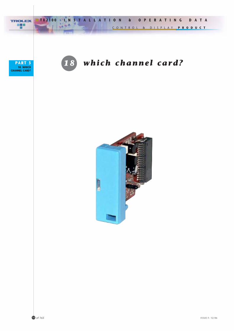
PART 318. WHICH
CHANNEL CARD?
18 which channel card?
P R O D U C T
155
I N S T A L L A T I O N & O P E R A T I N G D A T A
C O N T R O L & D I S P L A Y
of 165
T X 2 1 0 0
ISSUE F: 12/06

PART 318. WHICH
CHANNEL CARD?
PressureSensor
VibrationSensor
PressureSensor
T X 6 1 1 4
T X 5 6 3 4
ANALOGUE INPUT CHANNEL CARDS
4.. .20mA INPUT
TX2141.301
TX2141.302
••••••••••••••••••• Current regulated 4...20
process signals.
••••••••••••••••••• 2, 3 and 4 wire connections.
••••••••••••••••••• Loop powered sensors.
••••••••••••••••••• Sensors, signal loops,
process instruments.
TemperatureSensor
T X 6 2 7 4
VortexFlow Sensor
T X 6 2 7 3
Gas Sensor• Electrochemical• Infra Red• Pellistor
T X 6 3 6 3T X 6 3 7 3T X 6 3 8 3
T X 6 1 4 3T X 6 1 4 1
T X 5 6 3 8to
T X 5 9 2 1T X 5 9 2 2T X 5 9 2 3
SentroGas Sensor
T X 6 5 3 1T X 6 5 3 2
P R O D U C T
156
I N S T A L L A T I O N & O P E R A T I N G D A T A
C O N T R O L & D I S P L A Y
of 165
T X 2 1 0 0
ISSUE F: 12/06
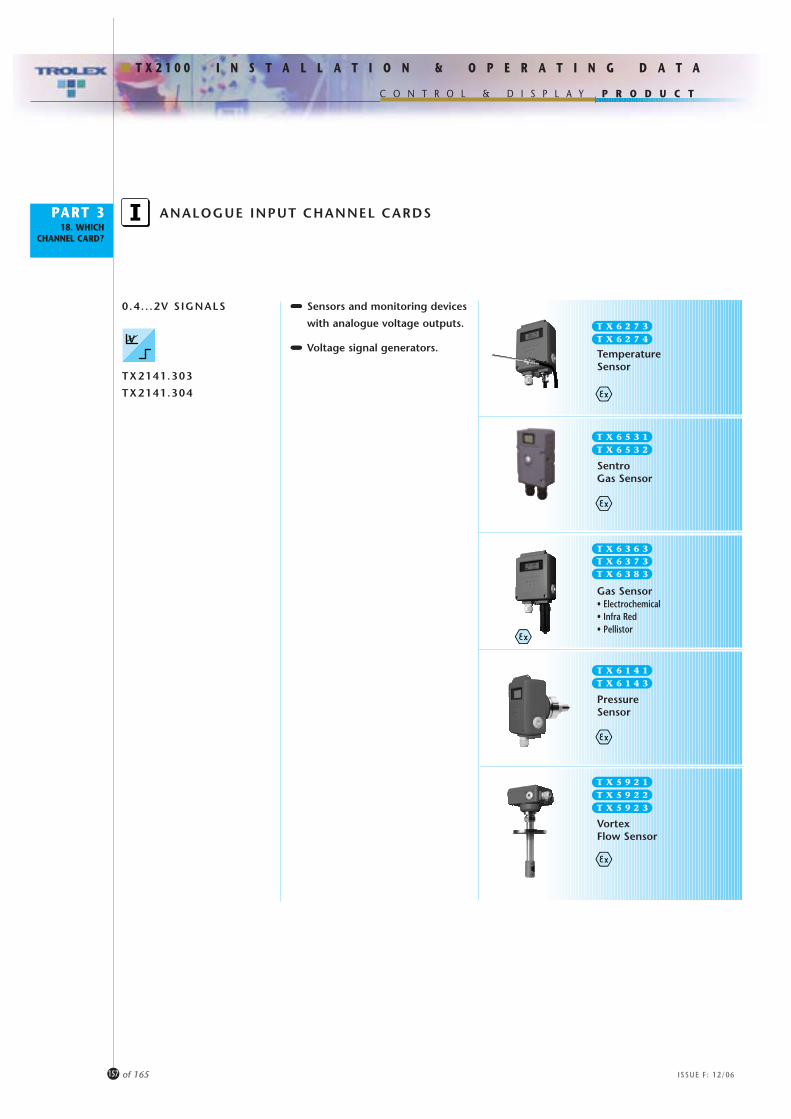
PART 318. WHICH
CHANNEL CARD?
PressureSensor
ANALOGUE INPUT CHANNEL CARDS
0.4. . .2V SIGNALS
TX2141.303
TX2141.304
••••••••••••••••••• Sensors and monitoring devices
with analogue voltage outputs.
••••••••••••••••••• Voltage signal generators.
Gas Sensor• Electrochemical• Infra Red• Pellistor
TemperatureSensor
T X 6 2 7 4
VortexFlow Sensor
T X 6 2 7 3
T X 6 3 6 3T X 6 3 7 3T X 6 3 8 3
T X 6 1 4 3T X 6 1 4 1
T X 5 9 2 1T X 5 9 2 2T X 5 9 2 3
SentroGas Sensor
T X 6 5 3 2T X 6 5 3 1
P R O D U C T
157
I N S T A L L A T I O N & O P E R A T I N G D A T A
C O N T R O L & D I S P L A Y
of 165
T X 2 1 0 0
ISSUE F: 12/06
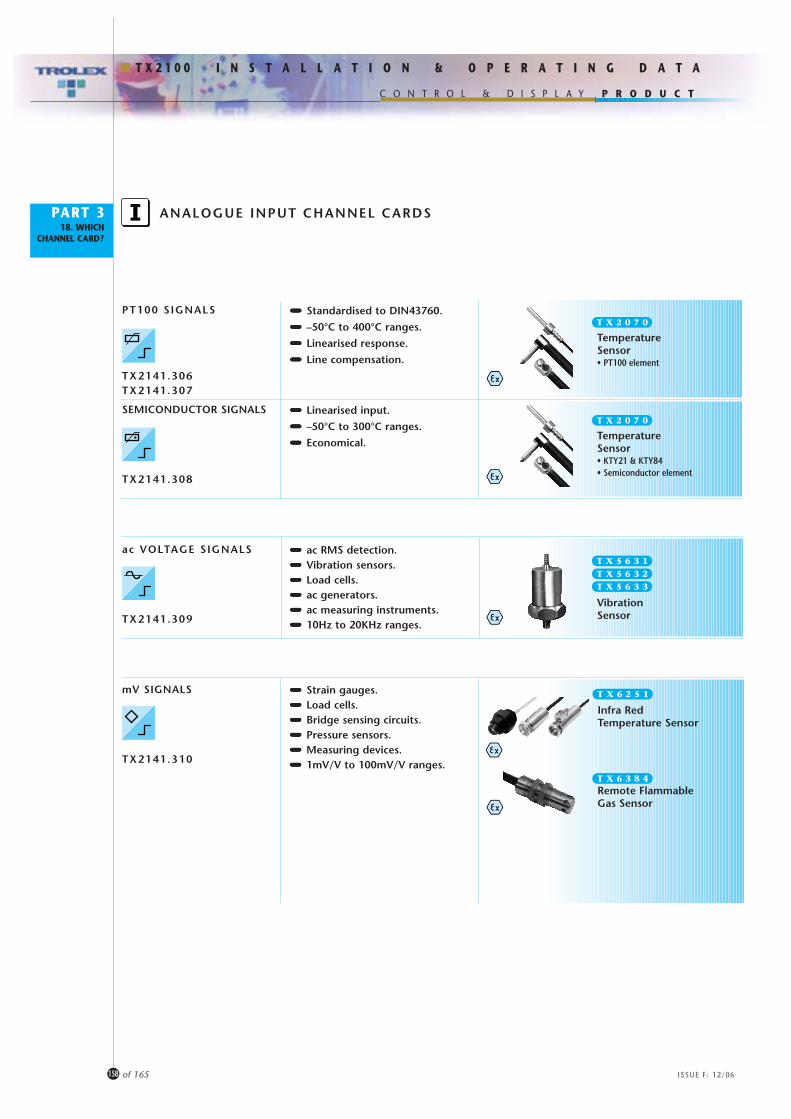
PART 318. WHICH
CHANNEL CARD?
ANALOGUE INPUT CHANNEL CARDS
••••••••••••••••••• Standardised to DIN43760.
••••••••••••••••••• –50°C to 400°C ranges.
••••••••••••••••••• Linearised response.
••••••••••••••••••• Line compensation.
••••••••••••••••••• Linearised input.
••••••••••••••••••• –50°C to 300°C ranges.
••••••••••••••••••• Economical.
••••••••••••••••••• ac RMS detection.••••••••••••••••••• Vibration sensors.••••••••••••••••••• Load cells.••••••••••••••••••• ac generators.••••••••••••••••••• ac measuring instruments.••••••••••••••••••• 10Hz to 20KHz ranges.
••••••••••••••••••• Strain gauges.••••••••••••••••••• Load cells.••••••••••••••••••• Bridge sensing circuits.••••••••••••••••••• Pressure sensors.••••••••••••••••••• Measuring devices.••••••••••••••••••• 1mV/V to 100mV/V ranges.
TemperatureSensor• PT100 element
T X 2 0 7 0
TemperatureSensor• KTY21 & KTY84• Semiconductor element
T X 2 0 7 0
VibrationSensor
T X 5 6 3 1T X 5 6 3 2T X 5 6 3 3
PT100 SIGNALS
TX2141.306TX2141.307
SEMICONDUCTOR SIGNALS
TX2141.308
ac VOLTAGE SIGNALS
TX2141.309
mV SIGNALS
TX2141.310
Infra RedTemperature Sensor
T X 6 2 5 1
Remote FlammableGas Sensor
T X 6 3 8 4
P R O D U C T
158
I N S T A L L A T I O N & O P E R A T I N G D A T A
C O N T R O L & D I S P L A Y
of 165
T X 2 1 0 0
ISSUE F: 12/06

PART 318. WHICH
CHANNEL CARD?
PULSE FREQUENCY INPUT CHANNEL CARDS
PULSE FREQUENCY INPUT
TX2141.401
••••••••••••••••••• Pulse or frequency signals.
••••••••••••••••••• Switches,proximity sensors,
pulse wheels, frequency
generators, photocells.
••••••••••••••••••• Frequency measurement,
speed sensing, slip monitoring,
differential frequency, pulse
comparison, frequency
generators.
••••••••••••••••••• Sensors with frequency outputs
5...15Hz, 0...10kHz etc.
••••••••••••••••••• Pulse generating flow sensing
devices and turbines.
••••••••••••••••••• Motor and conveyor
monitoring.
VortexFlowSensor
T X 5 9 2 4
T X 5 9 2 5
P R O D U C T
159
I N S T A L L A T I O N & O P E R A T I N G D A T A
C O N T R O L & D I S P L A Y
of 165
T X 2 1 0 0
ISSUE F: 12/06
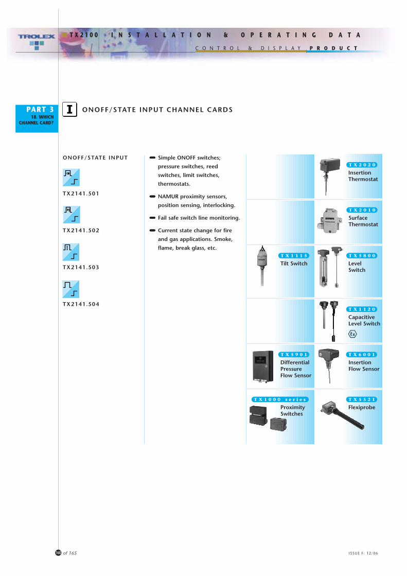
PART 318. WHICH
CHANNEL CARD?
ONOFF/STATE INPUT CHANNEL CARDS
ONOFF/STATE INPUT
TX2141.501
TX2141.502
TX2141.503
TX2141.504
••••••••••••••••••• Simple ONOFF switches;
pressure switches, reed
switches, limit switches,
thermostats.
••••••••••••••••••• NAMUR proximity sensors,
position sensing, interlocking.
••••••••••••••••••• Fail safe switch line monitoring.
••••••••••••••••••• Current state change for fire
and gas applications. Smoke,
flame, break glass, etc.
InsertionThermostat
T X 2 0 2 0
SurfaceThermostat
T X 2 0 1 0
Tilt Switch LevelSwitch
T X 1 1 1 5 T X 5 8 0 0
CapacitiveLevel Switch
T X 1 1 2 0
DifferentialPressureFlow Sensor
InsertionFlow Sensor
T X 5 9 0 1 T X 6 0 0 1
FlexiprobeProximitySwitches
T X 1 0 0 0 s e r i e s T X 5 5 2 1
P R O D U C T
160
I N S T A L L A T I O N & O P E R A T I N G D A T A
C O N T R O L & D I S P L A Y
of 165
T X 2 1 0 0
ISSUE F: 12/06

PART 318. WHICH
CHANNEL CARD?
ONOFF/STATE OUTPUT CHANNEL CARDS
ONOFF/STATE OUTPUT
TX2141.603
••••••••••••••••••• Solid state output switch.
••••••••••••••••••• Relay driver, small lamp driver,
logic driver.
••••••••••••••••••• Economical output switching.
••••••••••••••••••• Quad output – high density.
ONOFF/STATE OUTPUT
TX2141.604
••••••••••••••••••• Voltage free contact.
••••••••••••••••••• Isolated switching power for
relays, contactors and alarm
devices.
P R O D U C T
161
I N S T A L L A T I O N & O P E R A T I N G D A T A
C O N T R O L & D I S P L A Y
of 165
T X 2 1 0 0
ISSUE F: 12/06

PART 318. WHICH
CHANNEL CARD?
ANALOGUE OUTPUT CHANNEL CARDS
ANALOGUE OUTPUT
TX2141.701
••••••••••••••••••• Motorised valves,
servo controllers, process loops,
regulators, positioning devices
••••••••••••••••••• Signal repeaters
P R O D U C T
162
I N S T A L L A T I O N & O P E R A T I N G D A T A
C O N T R O L & D I S P L A Y
of 165
T X 2 1 0 0
ISSUE F: 12/06

PART 319. CONFORMITY
CHECK
19 conformity check
P R O D U C T
163
I N S T A L L A T I O N & O P E R A T I N G D A T A
C O N T R O L & D I S P L A Y
of 165
T X 2 1 0 0
ISSUE F: 12/06

PART 319. CONFORMITY
CHECK
••••••••••••••••••• Ensure the correct Supply Voltage system.
••••••••••••••••••• Ensure the correct Sensors and Plant Devices
24V dc
24V dc compatible
••••••••••••••••••• Ensure correct Datacomms compatibility for LAN1 and LAN2 and associated equipment.
••••••••••••••••••• Do the channel card types concur with the plant devices being used.
••••••••••••••••••• Fit DIN RAIL end clamps. Secure Commandbus cables.
••••••••••••••••••• Group II (02) Commander Modules MUST be mounted into approved metal housings.
••••••••••••••••••• Check that all terminals are properly tightened.
••••••••••••••••••• Segregate power and signal cabling.
••••••••••••••••••• Carry out a power audit of each Terminal Module (section 3.8).
••••••••••••••••••• Check that the total power consumption is within the power rating of the power supply being used and the limits
individually specified for Hazardous Area Commander Systems.
Command Module (section 2) mA
Terminal Modules (section 3.9) mA
Commandbus Repeater Modules (section 5.6) mA
TOTAL: mA
••••••••••••••••••• Check that the cable lengths do not exceed permissible restrictions.
••••••••••••••••••• Fit End-of-Line Termination Resistors on DISPERSED Commandbus systems (sections 5.6 and 5.7).
If more than one Power Supply is used on a Commander system ensure that interlinking
power conductors have been omitted from the commandbus (section 5.4).
P R O D U C T
164
I N S T A L L A T I O N & O P E R A T I N G D A T A
C O N T R O L & D I S P L A Y
of 165
T X 2 1 0 0
ISSUE F: 12/06

PART 3 20 approvals andcert i f icat ion
PART 320. APPROVALS
ANDCERTIFICATION
P R O D U C T
165
I N S T A L L A T I O N & O P E R A T I N G D A T A
C O N T R O L & D I S P L A Y
of 165
T X 2 1 0 0
ISSUE F: 12/06

PART 320. APPROVALS
ANDCERTIFICATION
Intrinsically Safe
The Commander system is certified Intrinsically Safe Group II apparatus foruse in potentially explosive atmospheres to EURONORM standards whenused with an approved power supply or safety barrier.
Group II: [EEx ia] IIC T4
The system is designed to comply with the ATEX directive (94/9/EEC).
Electro Magnetic Compatibility
The system is designed to comply with the EC directive on EMC(89/336/EEC).
ATEX
P R O D U C T
166
I N S T A L L A T I O N & O P E R A T I N G D A T A
C O N T R O L & D I S P L A Y
of 165
T X 2 1 0 0
ISSUE F: 12/06

P R O T E C T I N GT H E
E N V I R O N M E N T
Many of our products are often used to monitor the quality of environmental conditions consequently Trolex isalso particularly aware of the need to protect human health and the environment in which we live.
The Company has instituted a radical environment protection policy to ensure that all aspects of our manufacturingprogramme have the minimum possible detrimental impact on the environment. This covers all stages beginning withsustainable product design supported by careful selection of the materials used in their production, through tomanaged recovery and disposal at the end of the useful life of a product.
This policy also incorporates the principles of the Waste Electrical and Electronics Equipment (WEEE) directive, and theassociated Restriction of Hazardous Substances (RoHS) directive, to be implemented in EU countries.
Progress is already well advanced on the introduction of a completely new range of products that maximise thecentral principle of sustainable design with the intention of reducing the end-of-life cost to the end user.
All Trolex products are manufactured to exacting standards in accordance with our stringent quality control ethos.Having chosen to use one of our products will, in itself, guarantee extended durability and a long operating life,endorsed by our commitment to recycling and recovery.
All packaging materials are carefully selected to be bio-degradable or re-cycleable where possible.
All plastic materials are identified for recycling purposes and re-cycled materials are used where it is possible to do so.
Printing paper and material are sourced from suppliers that have a declared environmental management system.
Product design centred around high quality and long term durability. Modular architecture both in construction and software design suitable for future upgrades and adaptability to alternative duty.
Ease of product disassembly, minimisation of fixing devices, and clear separation of functional parts to benefit re-use and re-cycling.
Control and monitoring of suppliers of components and sub-assemblies. Deal only with suppliers that have a defined commitment to environmental monitoring principles.
Control the use of restricted substances within the design process. Deal only with suppliers that have a defined commitment to the control of restricted substances.
Provide an efficient high speed service within Trolex for repair, refurbishing and conversion of products for alternative duty.
Provision of an end-of-life product Take-back service for recovery, re-use, and recycling of electrical and electroniccomponents. Retain the packaging of a new product and re-use it to return the device to us at the end of its working life. Trolex will guarantee to recover all materials and components, where practicable and arrange for them to be re-cycled in an appropriate and in a safe manner.
TROLEX LIMITEDNewby Road, Haze l Grove, Stockport , Chesh i re SK7 5DY, UK.
T: +44 (0)161-483 1435E: sa les@tro lex .com W: www.tro lex .com
P R O D U C T
167
I N S T A L L A T I O N & O P E R A T I N G D A T A
C O N T R O L & D I S P L A Y
of 165
T X 2 1 0 0
ISSUE F: 12/06