ComfortPoint Open - Honeywell · ComfortPoint Open CPO-Rxx ROOM CONTROLLERS DATA SHEET Fig. 1....
12
® U.S. Registered Trademark Copyright © 2016 Honeywell Inc. ▪ All Rights Reserved EN0B-0732GE51 R0616 ComfortPoint Open CPO-Rxx ROOM CONTROLLERS DATA SHEET Fig. 1. CPO-Rxx (without optional covers) GENERAL The CPO-Rxx family of room controllers provide flexible, con- figurable, demand-led control that delivers tangible benefits to reduce energy spends and drives new levels of functionality and efficiency in today’s buildings. With scalable and freely programmable BACnet MS/TP-based room controllers, smart engineering & commissioning tools, and SYLK technology, multiple and flexible configurations can be achieved to address specific applications. FEATURES • Designed to control terminal units such as 2- and 4-pipe fan coil units, chilled ceilings, hydronic, air quality control, and a mix of these applications. • For complex applications requiring high I/O count. • Both configurable and freely programmable, covering enhanced applications. • Support for 1-3 stage fans, variable fan speed drives (VSDs), thermal, floating, and proportional actuators. • Dual-loop support allows for 2-room application. • Auto Mac-addressing. • Fast commissioning using plug-and-play solutions, pre- defined applications and state-of-the-art commissioning via the RoomUp mobile application – eliminating the need for two people when commissioning. • Reduced number of sensors because sensors are shared across different applications. • BACnet BTL®-Listed as Advanced Application Controllers (B-AAC) rev 1.12. • Two housing dimensions and several different I/O versions to match your individual needs. • 24 VAC and 230 VAC versions. • Universal mounting options, including terminal covers and color-coded terminals. • The 230 VAC models feature 24 VAC aux. output voltage, allowing direct connection and powering of field devices. • Two-wire polarity-insensitive bus interface to connect to Honeywell Sylk wall modules. • All models with real-time clock. RL4, RL5, RL6, and RL7U with super capacitor for 72-hr data retention. SYSTEM OVERVIEW Honeywell ComfortPoint Open PLANT CONTROLLER BACnet IP TCP/IP Wi-Fi BACnet IP TR42 TR42 TR42 TR42 TR42 TR42 CPO-R CPO-R CPO-R CPO-R BACnet Wi-Fi ADAPTER #1 ... #30 BACnet MS/TP BACnet MS/TP Fig. 2. System overview
Transcript of ComfortPoint Open - Honeywell · ComfortPoint Open CPO-Rxx ROOM CONTROLLERS DATA SHEET Fig. 1....

® U.S. Registered Trademark Copyright © 2016 Honeywell Inc. ▪ All Rights Reserved EN0B-0732GE51 R0616
ComfortPoint Open CPO-Rxx ROOM CONTROLLERS
DATA SHEET
Fig. 1. CPO-Rxx (without optional covers)
GENERAL The CPO-Rxx family of room controllers provide flexible, con-figurable, demand-led control that delivers tangible benefits to reduce energy spends and drives new levels of functionality and efficiency in today’s buildings. With scalable and freely programmable BACnet MS/TP-based room controllers, smart engineering & commissioning tools, and SYLK technology, multiple and flexible configurations can be achieved to address specific applications.
FEATURES • Designed to control terminal units such as 2- and 4-pipe
fan coil units, chilled ceilings, hydronic, air quality control, and a mix of these applications.
• For complex applications requiring high I/O count. • Both configurable and freely programmable, covering
enhanced applications. • Support for 1-3 stage fans, variable fan speed drives
(VSDs), thermal, floating, and proportional actuators. • Dual-loop support allows for 2-room application. • Auto Mac-addressing. • Fast commissioning using plug-and-play solutions, pre-
defined applications and state-of-the-art commissioning via the RoomUp mobile application – eliminating the need for two people when commissioning.
• Reduced number of sensors because sensors are shared across different applications.
• BACnet BTL®-Listed as Advanced Application Controllers (B-AAC) rev 1.12.
• Two housing dimensions and several different I/O versions to match your individual needs.
• 24 VAC and 230 VAC versions. • Universal mounting options, including terminal covers and
color-coded terminals. • The 230 VAC models feature 24 VAC aux. output voltage,
allowing direct connection and powering of field devices. • Two-wire polarity-insensitive bus interface to connect to
Honeywell Sylk wall modules. • All models with real-time clock. RL4, RL5, RL6, and RL7U
with super capacitor for 72-hr data retention.
SYSTEM OVERVIEW
HoneywellComfortPoint OpenTM
PLANTCONTROLLER
BACnet IPTCP/IP
Wi-FiBACnet IP
TR42 TR42TR42 TR42TR42 TR42
CPO-RCPO-RCPO-R CPO-R
BACnet Wi-FiADAPTER
#1 ... #30BACnet MS/TP BACnet MS/TP
Fig. 2. System overview

CPO-Rxx ROOM CONTROLLERS – DATA SHEET
EN0B-0732GE51 R0616 2
Table 1. Overview of models
OS no.: CPO-…
power supply
AOs UIs relays (N.O.)
triacs (24 / 230 VAC)
total no. of I/Os
max. 24 VAC output
remarks
larg
e h
ou
sin
g
(198
x 1
10 x
57.
5 m
m)
RL1 230 VAC 2 6 1 2 11 300 mA --
RL2 230 VAC 2 6 4 4 16 300 mA --
RL3 24 VAC 2 6 4 4 16 600 mA --
RL4 230 VAC 6 10 4 4 24 300 mA 72-hr data retention
RL5 24 VAC 6 10 4 4 24 600 mA 72-hr data retention; with removable terminals
RL6 24 VAC 6 10 4 4 24 600 mA 72-hr data retention
RL7U 24 VAC 6 10 4* 4 23 600 mA 72-hr data retention; with watchdog relay
RL8 230 VAC 6 10** 4 4 24 300 mA With lighting support
smal
l h
ou
sin
g
(162
x 1
10 x
57.
5 m
m)
RS1 230 VAC 3 3 0 0 6 300 mA --
RS2 230 VAC 1 3 0 2 6 300 mA Configurable, only
RS3 230 VAC 0 3 3 2 8 300 mA Configurable, only
RS4 230 VAC 4 4 4 2 14 300 mA --
RS5 24 VAC 4 4 4 2 14 600 mA --
RS6 24 VAC 1 3 0 2 6 600 mA Configurable, only
*Including relay 4 (the watchdog), which is not available for use by the application.
**UI1-UI4 are binary-only inputs.
CPU: 32-bit MK24FN Freescale Kinetis Cortex M4

CPO-Rxx ROOM CONTROLLERS – DATA SHEET
EN0B-0732GE51 R0616 3
DIMENSIONS AND MOUNTING Housings The controller is available in two housing sizes, both conforming to IP20:
▪ RLxx (large housing): W x L x H = 110 x 198 x 59 mm and
▪ RSxx (small housing): W x L x H = 110 x 162 x 59 mm
See also Fig. 3 and Fig. 4.
57
3.5
59
45
10
10
11053.5
52
REMOVABLETERMINALS
24-VMODELS
198
230-VMODELS
2
N
3
24V~
7
TN
8
T~
9
T01
10
TN
11
T02
12
T03
13
TN
14
T04
15
RC4
16
RO4
17
IN4
18
RN
19
RN
20
IN1
21
RO1
22
IN2
23
RO2
24
IN3
25
RO3
4
24V0
5
24V~
6
24V0
1
L
26
C2+ GND
28
24V~
2927
C2- WM1
30
WM2
31
3832AO1
34AO2
36AO3 AO4
40AO5
42AO6
33GND
3524V~
37GND
3924V~
41GND
4324V~
4424V~
46GND
48UI2
50UI3
52GND
54UI6
56UI7
58GND
60UI10
45LED
47UI1
49GND
51UI4
53UI5
55GND
57UI8
59UI9
61GND
62
C1+
63
C1- GND
64
BACnet MS/TPSERVICE
Fig. 3. RLxx dimensions (in mm)
NOTE: In the case of the RL5, all of the terminal blocks are removable.
57 59
3.5
45 110
10
10
REMOVABLETERMINALS
162
7
T01
8
TN
9
T02
1
L
2
N
3
24V~
4
24V0
5
TN
6
T~
10
RO4
11
IN4
12
RN
13
RN
14
IN1
15
RO1
16
IN2
17
RO2
18
IN3
19
RO3
WM120
C2+23
C2-24
WM221
34
UI1
36
UI2
37
UI3
39
UI4
35
GND
38
GND
26
AO1
27
24V~
28
GND
29
AO2
30
AO3
31
24V~
32
GND
33
AO4
41
C1-
40
C1+ GND
42
BACnet MS/TPSERVICE
2224V~
25GND
53.559
52
24-VMODELS
230-VMODELS
Fig. 4. RSxx dimensions (in mm)
The unit is suitable for mounting on a standard rail, on walls, as well as in wiring cabinets or fuse boxes.
Terminal Protection Covers for IP30 In the case of controllers mounted outside of a cabinet, before applying power to the device, Terminal Protection Covers (10-pc. bulk packs, order no.: IRM-RLC for large housings and IRM-RSC for small housings) must be mounted so as to provide IP30.
161
.65
198
54
58
.32
55
8.3
25
54
59
IRM-RLC(BULK PACK, 10 pcs.)
RLx RLx
Fig. 5. Large housing, with terminal protection covers, dimensions (in mm)
161
.65
54
58
.32
55
8.3
25
54
59
IRM-RSC(BULK PACK, 10 pcs.)
RSx RSx
162
Fig. 6. Small housing, with terminal protection covers, dimensions (in mm)
TERMINAL ASSIGNMENT General For a complete list of all terminals and a description of their functions, see Table 2 and Table 6.
Communication Interfaces All models of the controller features the following communi-cation interfaces:
▪ A Sylk Bus interface for connection to TR40x/42x Wall Modules;
▪ A BACnet MS/TP interface; ▪ An RJ45 connector for connection of the BACnet WiFi
Adapter.

CPO-Rxx ROOM CONTROLLERS – DATA SHEET
EN0B-0732GE51 R0616 4
Table 2. RSxx Room Controllers: Overview of terminals and functions (by model)
term. printing function RS1 RS2 RS3 RS4 RS5 RS6
1, 2 "L", "N" 230-V power supply X X X X -- --
3, 4 "24V~", "24V0" Removable 24-V power supply input -- -- -- -- X X
3, 4 "24V~", "24V0" Aux. output voltage (24 VAC) for all triacs X X X X -- --
5 "TN" Aux. term. for triac neutral wiring (internally connected with terminal 8)
-- X X X X X
6 "T~" Triac input voltage (24 VAC / 230 VAC) for all triacs; triac-switched
-- X X X X X
7 "T01" Triac-switched output -- X X X X X
8 "TN" Aux. term. for triac neutral wiring (internally connected with terminal 5)
-- X X X X X
9 "T02" Triac-switched output -- X X X X X
10, 11 "RO4", "IN4" Output of Relay 4, Input for Relay 4 -- -- -- type 2 type 2 --
12, 13 "RN", "RN" Aux. terminals for relay neutral wiring -- -- -- X X --
14, 15 "IN1", "RO1" Input for Relay 1, Output of Relay 1 -- -- type 1 type 1 type 1 --
16, 17 "IN2", "RO2" Input for Relay 2, Output of Relay 2 -- -- type 1 type 1 type 1 --
18, 19 "IN3", "RO3" Input for Relay 3, Output of Relay 3 -- -- type 1 type 1 type 1 --
20, 21 "WM1", "WM2" Removable interface for Sylk Bus X X X X X X
22, 23, 24, 25
"24V~", "C2+", "C2-", "GND"
Aux. power (24 VAC 20%, 50/60 Hz) + RS485 Modbus interface + corresp. GND
-- -- -- -- -- --
26 "AO1" Analog Output 1 type 2 type 2 -- type 2 type 2 type 2
27 "24V~" 24 VAC power for field devices X X -- X X X
28 "GND" Ground for AOs X X -- X X X
29 "AO2" Analog Output 2 type 1 -- -- type 1 type 1 --
30 "AO3" Analog Output 3 type 1 -- -- type 1 type 1 --
31 "24V~" 24 VAC power for field devices X -- -- X X --
32 "GND" Ground for AOs X -- -- X X --
33 "AO4" Analog Output 4 -- -- -- type 1 type 1 --
34 "UI1" Universal Input 1 type 1 type 1 type 1 type 1 type 1 type 1
35 "GND" Ground for UIs X X X X X X
36 "UI2" Universal Input 2 type 1 type 1 type 1 type 1 type 1 type 1
37 "UI3" Universal Input 3 type 1 type 1 type 1 type 1 type 1 type 1
38 "GND" Ground for UIs X X X X X X
39 "UI4" Universal Input 4 -- -- -- type 1 type 1 --
40, 41, 42
"C1+", "C1-", "GND"
Removable BACnet MS/TP interface and corresponding GND
X X X X X X
Relay output types: See Table 3. Universal input types: Table 4. Analog output types: See Table 5.
Table 3. Relay output types and characteristics
type 1
(standard) type 2
(high in-rush current) type 3
(watchdog)
corresponding ROs of RSxx RO1, RO2, RO3 RO4 --
corresponding ROs of RLxx RO2, RO3 RO1, RO4 RC4
contact N.-O. N.-O. N.-C. (CO)
min. load 5 VAC, 100 mA 24 VAC, 40 mA 5 VAC, 100 mA
switching voltage range 15 … 253 VAC 15 … 253 VAC 15 … 253 VAC
max. continuous load at 250 VAC (cos φ = 1) 4 A 10 A 1 A
max. continuous load at 250 VAC (cos φ = 0.6) 4 A 10 A 1 A
in-rush current (20 ms) -- 80 A --
usage fan motor light switching and fan
motor See section "Watchdog
Functionality (RL7U, only)"
NOTE: The max. sum load of all relay currents at the same time is 14 A.

CPO-Rxx ROOM CONTROLLERS – DATA SHEET
EN0B-0732GE51 R0616 5
Table 4. Universal input types and characteristics
type 1 type 2 type 3
UI1, UI2, UI3, UI4, UI5, UI6
UI7, UI8, UI9, UI10
UI1, UI2, UI3, UI4 (RL8, only)
dry contact (closed: res. <10 kΩ; open: res. > 20 kΩ; max. 0.2 Hz; pull-up voltage: 10 V)
X X --
dry contact (closed: res. <10 kΩ; open: res. > 20 kΩ; max. 0.2 Hz; pull-up voltage: 24 V); suitable for light switch applications
-- -- X
fast binary (=counter) input (max. 30 Hz; pulse ON = min. 16 ms; pulse OFF = min. 16 ms; closed: voltage < 1 V; open: voltage > 5 V; pull-up voltage: 10 V)
X X --
fast binary (=counter) input (max. 30 Hz; pulse ON = min. 16 ms; pulse OFF = min. 16 ms; closed: voltage < 1 V; open: voltage > 5 V; pull-up voltage: 24 V)
-- -- X
0(2) … 10 V X X --
NTC20kΩ X -- --
SetPoint and FanSpdSW (from T7460x) X -- --
NTC10kΩ X -- --
PT1000 + Ni1000TK5000 -- X --
Table 5. Analog output types and characteristics
type 1 type 2 type 3 type 4 type 5
output voltage 0…11 V
output current 0…1 mA 0…5 mA 0…10 mA 0…20 mA -1…+1 mA
min. accuracy ±150 mV
max. ripple ±100 mV
accuracy at zero point 0…200 mV ±150 mV

CPO-Rxx ROOM CONTROLLERS – DATA SHEET
EN0B-0732GE51 R0616 6
Table 6. RLxx Room Controllers: Overview of terminals and functions (by model)
term. printing function RL1 RL2 RL3 RL4 RL5 RL6 RL7U RL8 1, 2 "L", "N" 230-V power supply X X -- X -- -- -- X 3, 4 "24V~", "24V0" Removable 24-V power supply input -- -- X -- X X X -- 5, 6 "24V~", "24V0" Aux. output voltage (24 VAC) for all triacs X X X X X X X X
7 "TN" Aux. terminal for triac neutral wiring (internally connected with terminals 10 + 13) X X X X X X X X
8 "T~" Triac input voltage (24 VAC / 230 VAC) for all triacs; triac-switched X X X X X X X X
9 "T01" Triac-switched output X X X X X X X X
10 "TN" Aux. terminal for triac neutral wiring (internally connected with terminals 7 + 13) X X X X X X X X
11 "T02" Triac-switched output X X X X X X X X 12 "T03" Triac-switched output -- X X X X X X X
13 "TN" Aux. terminal for triac neutral wiring (internally connected with terminals 7 + 10) -- X X X X X X X
14 "T04" Triac-switched output -- X X X X X X X 15 "RC4" N.C. contact (watchdog) of Relay 4 -- -- -- -- -- -- type 3 -- 16, 17 "RO4", "IN4" Output of Relay 4, Input for Relay 4 type 2 type 2 type 2 type 2 type 2 type 2 type 2 type 2 18 "RN" Aux. terminal for relay neutral wiring X X X X X X X X 19 "RN" Aux. terminal for relay neutral wiring -- X X X X X X X 20, 21 "IN1", "RO1" Input for Relay 1, Output of Relay 1 -- type 2 type 2 type 2 type 2 type 2 type 2 type 2 22, 23 "IN2", "RO2" Input for Relay 2, Output of Relay 2 -- type 1 type 1 type 1 type 1 type 1 type 1 type 1 24, 25 "IN3", "RO3" Input for Relay 3, Output of Relay 3 -- type 1 type 1 type 1 type 1 type 1 type 1 type 1 26, 27, 28, 29
"C2+", "C2-", "GND", "24V~"
RS485 Modbus interface, corr. GND, + aux. power (24 VAC 20%, 50/60 Hz) -- -- -- -- -- -- -- --
30, 31 "WM1", "WM2" Removable interface for Sylk Bus X X X X X X X X 32 "AO1" Analog Output 1 type 3 type 3 type 3 type 3 type 3 type 3 type 3 type 4 33 "GND" Ground for AOs X X X X X X X X 34 "AO2" Analog Output 2 type 3 type 3 type 3 type 3 type 3 type 3 type 3 type 3 35 "24V~" 24 VAC power for field devices X X X X X X X X 36 "AO3" Analog Output 3 -- -- -- type 1 type 1 type 1 type 1 type 5 37 "GND" Ground for AOs -- -- -- X X X X X 38 "AO4" Analog Output 4 -- -- -- type 1 type 1 type 1 type 1 type 5 39 "24V~" 24 VAC power for field devices -- -- -- X X X X X 40 "AO5" Analog Output 5 -- -- -- type 1 type 1 type 1 type 1 type 1 41 "GND" Ground for AOs -- -- -- X X X X X 42 "AO6" Analog Output 6 -- -- -- type 1 type 1 type 1 type 1 type 1 43 "24V~" 24 VAC power for field devices -- -- -- X X X X X 44 "24V~" 24 VAC power for field devices X X X -- -- -- -- X 45 "LED" Output to LED of T7460C,E,F X X X -- -- -- -- X 46 "GND" Ground for UIs X X X X X X X X 47 "UI1" Universal Input 1 type 1 type 1 type 1 type 1 type 1 type 1 type 1 type 3 (BI)
48 "UI2" Universal Input 2 type 1 type 1 type 1 type 1 type 1 type 1 type 1 type 3 (BI)
49 "GND" Ground for UIs X X X X X X X X 50 "UI3" Universal Input 3 type 1 type 1 type 1 type 1 type 1 type 1 type 1 type 3 (BI)
51 "UI4" Universal Input 4 type 1 type 1 type 1 type 1 type 1 type 1 type 1 type 3 (BI)
52 "GND" Ground for UIs X X X X X X X X 53 "UI5" Universal Input 5 type 1 type 1 type 1 type 1 type 1 type 1 type 1 type 1 54 "UI6" Universal Input 6 type 1 type 1 type 1 type 1 type 1 type 1 type 1 type 1 55 "GND" Ground for UIs X X X X X X X X 56 "UI7" Universal Input 7 -- -- -- type 2 type 2 type 2 type 2 type 2 57 "UI8" Universal Input 8 -- -- -- type 2 type 2 type 2 type 2 type 2 58 "GND" Ground for UIs -- -- -- X X X X X 59 "UI9" Universal Input 9 -- -- -- type 2 type 2 type 2 type 2 type 2 60 "UI10" Universal Input 10 -- -- -- type 2 type 2 type 2 type 2 type 2 61 "GND" Ground for UIs -- -- -- X X X X X
62, 63, 64 "C1+", "C1-", "GND"
Removable BACnet MS/TP interface and corresponding GND X X X X X X X X
Relay output types: See Table 3. Universal input types: Table 4. Analog output types: See Table 5.
CPO-Rxx ROOM CONTROLLERS – DATA SHEET
EN0B-0732GE51 R0616 7
8 7 6 5 4 3 2 1
RJ45 INTERFACE
BACnet MS/TP
20WM1
21WM2
26AO1
32GND
34UI1
36UI2
37UI3
3COM
1TEMP
2SETP
29AO2
30AO3
33AO4
PROP.COOL
THERM.COOL
THERM.HEAT
ELECTR.REHEATER
3-SPEEDFAN
PROP.HEAT
T7460B1009 WALL MODULE
TR40x/TR42xWALL MODULE
1L
2N
5TN
6T~
7T01
8TN
9T02
NLN TIN RIN NN FIN
10RO4
11IN4
12RN
13RN
14IN1
15RO1
16IN2
17RO2
18IN3
19RO3
OCCUPANCY CONTACT
28GND
2724V~
3124V~
39UI4
35GND
38GND
40C1+
41C1-
42GND
RoomUp App onSMARTPHONE
BACnet WiFiADAPTER
RJ45PLUG
7 8 2,3,5,6 4
324V~
424V0
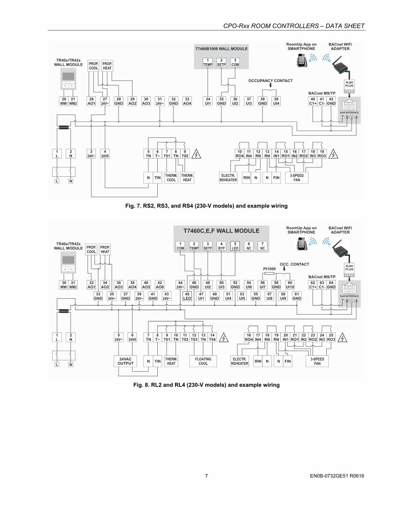
Fig. 7. RS2, RS3, and RS4 (230-V models) and example wiring
8 7 6 5 4 3 2 1
RJ45 INTERFACE
30WM1
31WM2
32AO1
3924V~
4324V~
4424V~
37GND
41GND
46GND
48UI2
50UI3
52GND
54UI6
56UI7
58GND
60UI10
2TEMP
3SETP
4BYP
6NC
7NC
47UI1
49GND
51UI4
53UI5
55GND
57UI8
59UI9
61GND
34AO2
36AO3
38AO4
40AO5
42AO6
PROP.COOL
THERM.HEAT
FLOATINGCOOL
ELECTR.REHEATER
3-SPEEDFAN
24VACOUTPUT
PROP.HEAT
Pt1000
T7460C,E,F WALL MODULE
TR40x/TR42xWALL MODULE
1L
2N
524V~
624V0
7TN
NLN TIN RIN NN FIN
16RO4
17IN4
8T~
9T01
10TN
11T02
12T03
13TN
14T04
18RN
19RN
20IN1
21RO1
22IN2
23RO2
24IN3
25RO3
OCC. CONTACT
7 8 2,3,5,6
5LED
45LED
62C1+
63C1-
64GND
BACnet MS/TP
4
BACnet WiFiADAPTER
RJ45PLUG
RoomUp App onSMARTPHONE
3524V~
33GND
1COM
Fig. 8. RL2 and RL4 (230-V models) and example wiring
CPO-Rxx ROOM CONTROLLERS – DATA SHEET
EN0B-0732GE51 R0616 8
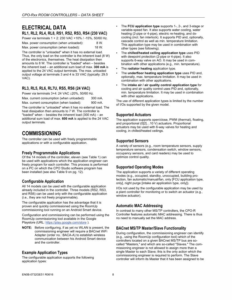
ELECTRICAL DATA RL1, RL2, RL4, RL8, RS1, RS2, RS3, RS4 (230 VAC) Power via terminals 1 + 2: 230 VAC +10% / -15%, 50/60 Hz.
Max. power consumption (when unloaded): 8 W. Max. power consumption (when loaded): 18 W.
The controller is "unloaded" when it has no external load. Thus, the only load on the controller is the inherent load (8 W) of the electronics, themselves. The heat dissipation then amounts to 8 W. The controller is "loaded" when – besides the inherent load – an additional sum load of max. 300 mA is applied to the 24 VAC output terminals. The max. unloaded output voltage at terminals 3 and 4 is 33 VAC (typically: 29.5 VAC).
RL3, RL5, RL6, RL7U, RS5, RS6 (24 VAC) Power via terminals 3+4: 24 VAC 20%, 50/60 Hz.
Max. current consumption (when unloaded): 300 mA. Max. current consumption (when loaded): 900 mA.
The controller is "unloaded" when it has no external load. The heat dissipation then amounts to 7 W. The controller is "loaded" when – besides the inherent load (300 mA) – an additional sum load of max. 600 mA is applied to the 24 VAC output terminals.
COMMISSIONING The controller can be used with freely programmable applications or with a configurable application.
Freely Programmable Applications Of the 14 models of the controller, eleven (see Table 1) can be used with applications which the application engineer can freely program for each controller. This process is performed on a PC on which the CPO Studio software program has been installed (see also Table 9 on pg. 12).
Configurable Application All 14 models can be used with the configurable application already included in the controller. Three models (RS2, RS3, and RS6) can be used only with the configurable application (i.e., they are not freely programmable).
The configurable application has the advantage that it is proven and quickly commissioned using the RoomUp commissioning tool running on an Android Smart device.
Configuration and commissioning can be performed using the RoomUp commissioning tool available in the Google Playstore (URL: https://play.google.com/store ).
NOTE: Before configuring, if as yet no WLAN is present, the commissioning engineer will require a BACnet WiFi Adapter (order no.: BACA-A) to establish wireless communication between his Android Smart device and the controller.
Example Application Types The configurable application supports the following application types:
▪ The FCU application type supports 1-, 2-, and 3-stage or variable-speed fan. It also supports water cooling, water heating (2-pipe or 4-pipe), electric re-heating, and dx-cooling (incl. fan interlock). It supports PID and, optionally, cascade control as well as min. temperature limitation. This application type may be used in combination with other types (see following).
▪ The chilled/heated ceiling application type uses PID with dewpoint protection (2-pipe or 4-pipe). It also supports 6-way valve on AO. It may be used in com-bination with other applications (e.g., min. temperature).
▪ The radiator heating application type.
▪ The underfloor heating application type uses PID and, optionally, max. temperature limitation. It may be used in combination with other applications.
▪ The intake air / air quality control application type for cooling and air quality control uses PID and, optionally, min. temperature limitation. It may be used in combination with other applications.
The use of different application types is limited by the number of I/Os supported by the given model.
Supported Actuators The application supports open/close, PWM (thermal), floating, and proportional (0[2]…10 V) actuators. Proportional actuators may be used with 6-way valves for heating and cooling, in chilled/heated ceilings.
Supported Sensors A variety of sensors (e.g., room temperature sensors, supply temperature sensors, condensation switch, window sensors, occupancy sensors, and card readers) may be used to optimize control quality.
Supported Operating Modes The application supports a variety of different operating modes (e.g., occupied, standby, unoccupied, building pro-tection, fan automatic/manual/fan, only [FCU application type, only], night purge [intake air application type, only]).
I/Os not used by the configurable application may be used by a plant controller for monitoring or to switch an actuator (e.g., window actuator).
Automatic MAC Addressing In contrast to many other MS/TP controllers, the CPO-R Controller features automatic MAC addressing. There is thus no need to manually set the MAC address.
BACnet MS/TP Master/Slave Functionality During configuration, the commissioning engineer can identify (e.g., using the RoomUp configuration tool) which of the controllers located on a given BACnet MS/TP bus are so-called "Masters," and which are so-called "Slaves." The com-missioning engineer is not allowed to assign more than a single Master to each Slave; this is the only action which the commissioning engineer is required to perform. The Slave controller will inform its Master that it has been assigned to be
CPO-Rxx ROOM CONTROLLERS – DATA SHEET
EN0B-0732GE51 R0616 9
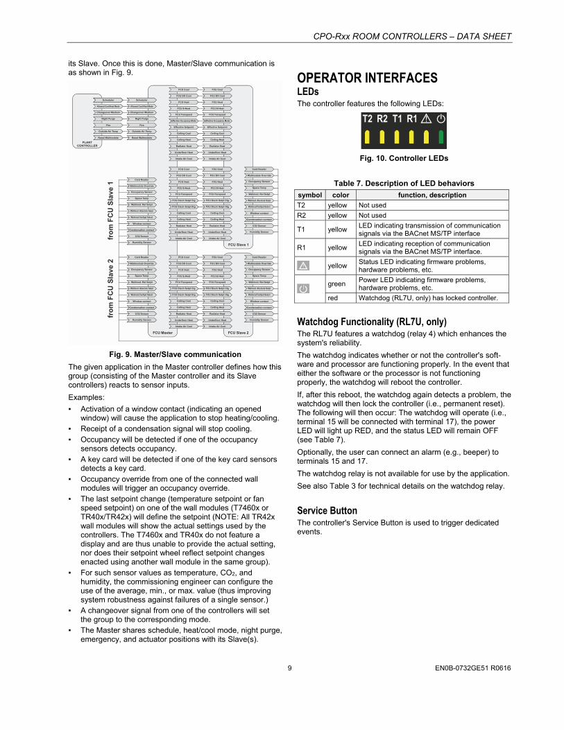
its Slave. Once this is done, Master/Slave communication is as shown in Fig. 9.
PLANTCONTROLLER
XXXXXXXXSchedulerScheduler Scheduler
FCU Cool FCU Cool
FCU Cool
FCU Cool FCU Cool
FCU Cool
FCU DX Cool FCU DX Cool
FCU DX Cool
FCU DX Cool FCU DX Cool
FCU DX Cool
FCU Heat FCU Heat
FCU Heat
FCU Heat FCU Heat
FCU Heat
FCU E-Heat FCU E-Heat
FCU E-Heat
FCU E-Heat FCU E-Heat
FCU E-Heat
FCU Fanspeed FCU Fanspeed
FCU Fanspeed
FCU Fanspeed FCU Fanspeed
FCU Fanspeed
Effective Occupancy Mode Effective Occupancy Mode
FCU Disch Setpt Clg
FCU Disch Setpt Clg FCU Disch Setpt Clg
FCU Disch Setpt Clg
Effective Setpoint Effective Setpoint
FCU Disch Setpt Htg
FCU Disch Setpt Htg FCU Disch Setpt Htg
FCU Disch Setpt Htg
Ceiling Cool Ceiling Cool
Ceiling Cool
Ceiling Cool Ceiling Cool
Ceiling Cool
Ceiling Heat Ceiling Heat
Ceiling Heat
Ceiling Heat Ceiling Heat
Ceiling Heat
Allowed Cool/Heat Mode Allowed Cool/Heat Mode
Changeover Medium Changeover Medium
Night Purge Night Purge
Fire Fire
Outside Air Temp Outside Air Temp
Reset Wallmodule Reset Wallmodule
Radiator Heat Radiator Heat
Radiator Heat
Radiator Heat Radiator Heat
Radiator Heat
Underfloor Heat Underfloor Heat
Underfloor Heat
Underfloor Heat Underfloor Heat
Underfloor Heat
Intake Air Cool Intake Air Cool
Intake Air Cool
Intake Air Cool Intake Air Cool
Intake Air Cool
Card Reader
Card ReaderCard Reader
Card Reader
Wallmodule Override
Wallmodule OverrideWallmodule Override
Wallmodule Override
Occupancy Sensor
Occupancy SensorOccupancy Sensor
Occupancy Sensor
Space Temp
Space TempSpace Temp
Space Temp
Wallmod. Rel Setpt
Wallmod. Rel SetptWallmod. Rel Setpt
Wallmod. Rel Setpt
Wallmod. Absolute Setpt
Wallmod. Absolute SetptWallmod. Absolute Setpt
Wallmod. Absolute Setpt
Wallmod.FanSpd Select
Wallmod.FanSpd SelectWallmod.FanSpd Select
Wallmod.FanSpd Select
Window contact
Window contact
Window contact
Window contact
Condensation contact
Condensation contact
Condensation contact
Condensation contact
CO2 Sensor
CO2 Sensor
CO2 Sensor
CO2 Sensor
Humidity Sensor
Humidity Sensor
Humidity Sensor
Humidity Sensor
FCU Slave 1
FCU Slave 2FCU Master
fro
m F
CU
Sla
ve
2fr
om
FC
U S
lav
e 1
Fig. 9. Master/Slave communication
The given application in the Master controller defines how this group (consisting of the Master controller and its Slave controllers) reacts to sensor inputs.
Examples:
▪ Activation of a window contact (indicating an opened window) will cause the application to stop heating/cooling.
▪ Receipt of a condensation signal will stop cooling. ▪ Occupancy will be detected if one of the occupancy
sensors detects occupancy. ▪ A key card will be detected if one of the key card sensors
detects a key card. ▪ Occupancy override from one of the connected wall
modules will trigger an occupancy override. ▪ The last setpoint change (temperature setpoint or fan
speed setpoint) on one of the wall modules (T7460x or TR40x/TR42x) will define the setpoint (NOTE: All TR42x wall modules will show the actual settings used by the controllers. The T7460x and TR40x do not feature a display and are thus unable to provide the actual setting, nor does their setpoint wheel reflect setpoint changes enacted using another wall module in the same group).
▪ For such sensor values as temperature, CO2, and humidity, the commissioning engineer can configure the use of the average, min., or max. value (thus improving system robustness against failures of a single sensor.)
▪ A changeover signal from one of the controllers will set the group to the corresponding mode.
▪ The Master shares schedule, heat/cool mode, night purge, emergency, and actuator positions with its Slave(s).
OPERATOR INTERFACES LEDs The controller features the following LEDs:
T2 R2 T1 R1 !
Fig. 10. Controller LEDs
Table 7. Description of LED behaviors
symbol color function, description
T2 yellow Not used
R2 yellow Not used
T1 yellow LED indicating transmission of communication signals via the BACnet MS/TP interface
R1 yellow LED indicating reception of communication signals via the BACnet MS/TP interface.
! yellow Status LED indicating firmware problems, hardware problems, etc.
green
Power LED indicating firmware problems, hardware problems, etc.
red Watchdog (RL7U, only) has locked controller.
Watchdog Functionality (RL7U, only) The RL7U features a watchdog (relay 4) which enhances the system's reliability.
The watchdog indicates whether or not the controller's soft-ware and processor are functioning properly. In the event that either the software or the processor is not functioning properly, the watchdog will reboot the controller.
If, after this reboot, the watchdog again detects a problem, the watchdog will then lock the controller (i.e., permanent reset). The following will then occur: The watchdog will operate (i.e., terminal 15 will be connected with terminal 17), the power LED will light up RED, and the status LED will remain OFF (see Table 7).
Optionally, the user can connect an alarm (e.g., beeper) to terminals 15 and 17.
The watchdog relay is not available for use by the application.
See also Table 3 for technical details on the watchdog relay.
Service Button The controller's Service Button is used to trigger dedicated events.

CPO-Rxx ROOM CONTROLLERS – DATA SHEET
EN0B-0732GE51 R0616 10
COMMUNICATION INTERFACES BACnet MS/TP Interface The controller features an RS485 interface (RLx: terminals 62, 63, and 64; RSx: terminals 40, 41, and 42) suitable for BACnet MS/TP communication. The terminal block containing it is black. The cable length affects the baud rate. See Table 8.
Table 8. Baud rate vs. max. cable length
baud rate max. cable length (L)
9.6, 19.2, 38.4, 57.6, and 76.8 kbps 1200 m
115.2 kbps 800 m
For information on wire gauge, max. permissible cable length, possible shielding and grounding requirements, and the max. number of devices which can be connected to a bus, refer to standard EIA-485.
RJ45 Connector for BACnet WiFi Adapter
CPO-RLx(CPO-RSx)
8 7 6 5 4 3 2 1
7 8 42,3,5,6
RJ45 CONNECTOR
INTERNALCONNECTIONS
BACnet MS/TP62
(40)C1+
63(41)C1-
64(42)GND
1 = DETECT2 = GND3 = GND4 = 24VAC5 = GND6 = GND7 = C1+8 = C1-
SMART-PHONE
BACnet WiFiADAPTER
RJ45PLUG
Fig. 11. RJ45 interface and BACnet WiFi Adapter
CAUTION It is permitted to connect only the BACnet WiFi Adapter to this RJ45 connector. Do not connect IP!
A BACnet WiFi Adapter can be connected to the controller's RJ45 connector in order to establish wireless communication with an Android Smart device so that the application engineer can configure the controller (using the RoomUp configuration tool).
NOTE: When the BACnet WiFi Adapter is connected to the controller's RJ45 connection, it is powered by the controller. It is then prohibited to simultaneously power the BACnet WiFi Adapter via a wall adapter. When, on the other hand, the BACnet WiFi Adapter is instead connected to the controller's BACnet MS/TP interface, it is prohibited to simultaneously use an RJ45 plug; instead, the BACnet WiFi Adapter must then be powered by a wall adapter (standard 5-V USB wall adapter with micro USB connector).
See also corresponding Technical Literature listed in Table 9 on pg. 12.
Wall Modules The T7460x and TR40x/TR42x Wall Modules can be used in conjunction with the controller to perform room temperature sensing, setpoint adjustment, fan speed manual override, and occupancy override.

CPO-Rxx ROOM CONTROLLERS – DATA SHEET
EN0B-0732GE51 R0616 11
I/O TERMINALS Relay Outputs
CAUTION Mixing of different voltages (e.g., 24 V and 230 V) within the relay block is not allowed.
The terminal blocks containing the controller's relay outputs are orange. Relay output types: See Table 3.
NOTE: If inductive components are to be connected to the relays and if these relays switch more often than once every two minutes, these components must be prevented from causing harmful interference to radio or television reception (conformance with EN 45014).
Triac Outputs The terminal blocks containing the controller's triac outputs are orange.
These triac outputs can be configured (using, e.g., the RoomUp configuration tool) for a variety of different functions, e.g., for connection to either a floating drive or to a thermal actuator. Once the triac outputs have been configured, the corresponding devices can then be connected to them directly.
NOTE: The VC6983 actuator is intended for use at relay outputs, only and must not be used at the controller's triac outputs.
Triac Current Limitations In the case of the 230-VAC versions of the controller, when the triacs are to be supplied with 24-VAC power from the con-troller's internal transformer, then the following applies:
▪ 300 mA max., i.e., a max. of one thermal actuator for heating and one thermal actuator for cooling can be operated (provided that heating and cooling are not operated at the same time).
CAUTION The max. permissible power output of all 24 VAC terminals combined is 300 mA! If the triacs, alone, are loaded with 300 mA, then it is not permitted to connect a load at any other 24 VAC output terminal.
In all other cases, when the triacs are to be supplied with power (24 VAC or 230 VAC) from an external source, then the following applies:
▪ 700 mA (peak) and 600 mA (max.), i.e., two to three thermal actuators can be operated in parallel (depending upon the current consumption of the given actuator).
Universal Inputs The terminal blocks containing the controller's universal outputs are blue. Universal input types: See Table 4.
The universal inputs are protected against voltages of max. 29 VAC and 30 VDC (due to, e.g., miswiring).
Bias Resistors Each universal input is equipped with one bias resistor.
Analog Outputs The terminal blocks containing the controller's analog outputs are green. Analog output types: See Table 5.
The analog outputs of the RLxx controllers (large housing) are protected against voltages of max. 29 VAC and 30 VDC (due to, e.g., miswiring).
NOTE: Connecting 24 VAC to any analog output of the RSxx controllers (small housing) will damage the hardware.

CPO-Rxx ROOM CONTROLLERS – DATA SHEET
Manufactured for and on behalf of the Environmental & Energy Solutions Division of Honeywell Technologies Sàrl, Rolle, Z.A. La Pièce 16, Switzerland by its Authorized Representative: Automation and Control Solutions Honeywell GmbH Böblinger Strasse 17 71101 Schönaich, Germany Phone +49 (0) 7031 637 01 Fax +49 (0) 7031 637 740 http://ecc.emea.honeywell.com EN0B-0732GE51 R0616 Subject to change without notice
TROUBLESHOOTING All units feature a Service LED, Power LED, and Service Button for commissioning and troubleshooting. See also sections "LEDs", "Watchdog Functionality (RL7U, only)", and "Service Button".
Check if the Service LED's behavior is changed if you switch the power OFF/ON. Please contact Honeywell if this does not solve the problem.
ACCESSORIES Terminal Protection Cover Required for wall mounting. Bulk pack, set of ten covers.
For LARGE controllers, order no.: IRM-RLC
For SMALL controllers, order no.: IRM-RSC
APPROVALS, CERTIFICATIONS, AND STANDARDS Approvals and Certifications 24-V models and 230-V models: UL 60730-1, Standard for
Automatic Electric Controls for Household and Similar Use, Part 1: General Requirements;
24-V models and 230-V models: CAN/CSA-E60730-1:02, Standard for Automatic Electrical Controls for Household and Similar Use, Part 1: General Requirements;
24-V models and 230-V models: Complementary listing for UL916, CSA C22.2 No. 205;
BACnet AAC profile; CE-approved; SASO and EAC-approved; FCC part 15B-compliant.
Classification according to EN 60730-1 EN 60730 sub part: EN 60730-2-9 Environmental conditions: For use in home (residential,
commercial, and light-industrial) environments
Construction: Independently mounted electronic control unit with fixed wiring; panel-mounted on DIN rail
Action: type 1.C Rated impulse voltage: 230 V circuits: 2500 V
24 V circuits: 500 V Pollution degree: 2 Protection against shock: Class 0 (without terminal cover)
Class II (with terminal cover) Software class: A
Classification according to EN 60529 (Degree of protection provided by enclosures)
IP20. In the case of controllers mounted outside of a cabinet, before applying power to the device, Terminal Protection Covers (10-pc. bulk packs, order no.: IRM-RLC for large housings and IRM-RSC for small housings) must be mounted so as to provide IP30.
Ambient Environmental Limits 24-V Models (5…95% r.H., non-condensing) Operating temperature: 0 … +50 °C
(RL7U: -40 … +65 °C)
Storage temperature: -20 … +70 °C
230-V Models (5…95% r.H., non-condensing) Operating temperature (floor/ceiling mounting): 0 … +40 °C
Operating temperature (wall/rail mounting): 0 … +50 °C
Storage temperature: -20 … +70 °C
RELATED TECHNICAL LITERATURE Table 9. Related Technical Literature
Title Product Lit. no.
CPO-Rxx Room Controller – Mount. Instr. MU1B-0590GE51
CPO-Rxx Room Controller – Data Sheet EN0B-0732GE51
CPO-Rxx Room Controller – Inst. & Comm. Instr. EN1B-0591GE51
BACnet WiFi Adapter – Product Data EN0B-0733GE51
BACnet WiFi Adapter – Mounting & Op. Instr. MU1B-0592GE51
ComfortPoint Open Studio– User's Guide EN1B-0001IE10
ComfortPoint Open Studio Online – User's Guide EN1B-0002IE10
ComfortPoint Open Studio – Installation Guide EN1B-0004IE10
ComfortPoint Open Studio Online – Inst. Guide EN1B-0011IE10
ComfortPoint Open Studio – User's Guide EN2B-0001IE10
ComfortPoint Open Online – User's Guide EN2B-0002IE10
ComfortPoint Open – System Engineering Guide EN2B-0052IE10
ComfortPoint Open Room Contr. – App. Guide EN2B-0053IE10
T7460A,B,C,D,E,F – Specification Data EN0B-0236GE51
T7460A,B,C,D,E,F – Installation Instructions EN1B-0291GE51
TR40x/TR42x – Specification Data 63-1389
Trademark Information BACnetTM is a trademark of ASHRAE Inc.
ComfortPointTM Open is a trademark of Honeywell Inc.