Combining Optimisation with Dymola to Calibrate a 2 Modelling and simulation of systems...
20
Copyright © Claytex Services Limited 2016 Combining Optimisation with Dymola to Calibrate a 2-zone Predictive Combustion Model. Mike Dempsey Optimised Engineering Design Conference 2016
Transcript of Combining Optimisation with Dymola to Calibrate a 2 Modelling and simulation of systems...

Copyright © Claytex Services Limited 2016
Combining Optimisation with Dymola to Calibrate
a 2-zone Predictive Combustion Model.
Mike Dempsey
Optimised Engineering Design Conference 2016

Copyright © Claytex Services Limited 2016
Claytex Services Limited
• Based in Leamington Spa, UK
– Office in Cape Town, South Africa
• Experts in Systems Engineering, Modelling and Simulation
• Business Activities
– Engineering consultancy
– Software sales and support
– Modelica library developers
– FMI tool developers
– Training services
• Dassault Systemes Certified Education
Partner
• Global customer base
– Europe, USA, India, South
Korea, Japan
Software, Consultancy, Training
Copyright © Claytex Services Limited 2016
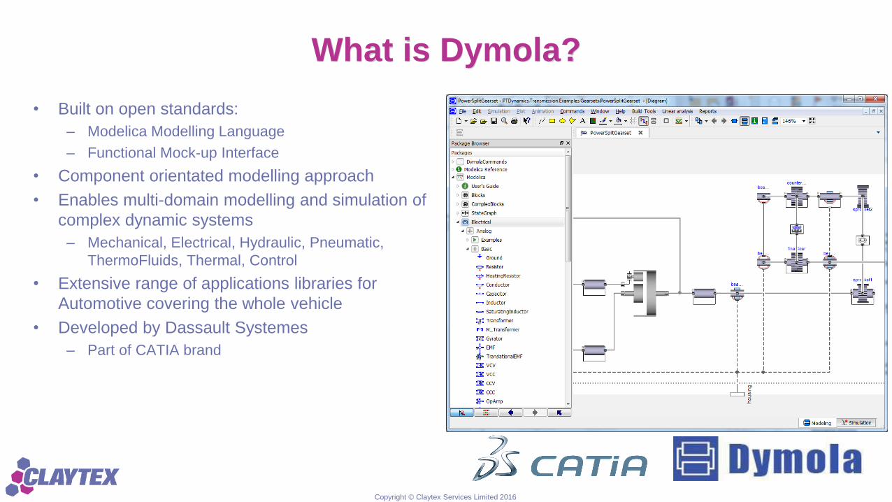
What is Dymola?
• Built on open standards:
– Modelica Modelling Language
– Functional Mock-up Interface
• Component orientated modelling approach
• Enables multi-domain modelling and simulation of
complex dynamic systems
– Mechanical, Electrical, Hydraulic, Pneumatic,
ThermoFluids, Thermal, Control
• Extensive range of applications libraries for
Automotive covering the whole vehicle
• Developed by Dassault Systemes
– Part of CATIA brand

Copyright © Claytex Services Limited 2016
Component Orientated Modelling
• Modelling and simulation of systems integrating
multiple physical domains
– Mechanics (1D, MultiBody), 1D Thermofluids,
Control, Thermal, Electrical, Magnetics and more
• Promotes extensive model reuse at component
and system level
– Components represent physical parts: valves,
gears, motor
– Connections between parts describe the physical
connection (mechanical, electrical, thermal, signal,
etc.)
• Store your own component and system models in
libraries to easily share and reuse them across
the business
Copyright © Claytex Services Limited 2016
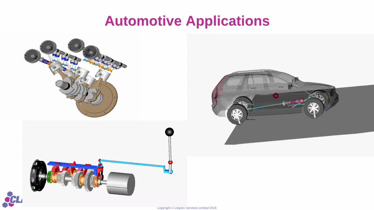
Automotive Applications

Copyright © Claytex Services Limited 2016
Challenges
• Market demands
– Improved fuel economy
– Lower emissions
– Improved reliability
– Noise quality
– Driveability
– Performance
• Engineering solutions
– More active systems
• Increases complexity
– Better control of existing systems
• Increasingly complex control requiring large calibration effort
– Tighter integration of all vehicle systems
• Management demands
– Faster time to market
– Lower development and manufacturing cost
Copyright © Claytex Services Limited 2016
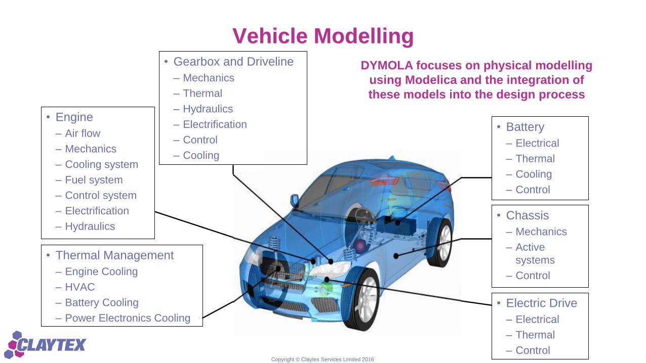
Vehicle Modelling
• Engine
– Air flow
– Mechanics
– Cooling system
– Fuel system
– Control system
– Electrification
– Hydraulics
• Battery
– Electrical
– Thermal
– Cooling
– Control
• Chassis
– Mechanics
– Active
systems
– Control
• Thermal Management
– Engine Cooling
– HVAC
– Battery Cooling
– Power Electronics Cooling
• Gearbox and Driveline
– Mechanics
– Thermal
– Hydraulics
– Electrification
– Control
– Cooling
DYMOLA focuses on physical modelling
using Modelica and the integration of
these models into the design process
• Electric Drive
– Electrical
– Thermal
– Control

Copyright © Claytex Services Limited 2016
The need for physical modelling
• Automotive products are complex systems
covering many domains
– Mechanical, Electrical, Hydraulic, Pneumatic,
Thermal, Chemical, Control, Magnetic, …
• No longer sensible to wait for prototypes to verify
that all these systems interact in a good way
• It’s not practical, or perhaps even possible, to fully
verify and validate control systems using
prototypes
• Need to use predictive models and not just
functional ones to make simulation useful from an
early stage of the project
• Need a complete virtual test environment

Copyright © Claytex Services Limited 2016
Functional and Predictive models
• A Functional model is one that captures the key function of the model
• A Predictive model allows us to predict the behaviour and explore it’s characteristics
• The clutch is there to make sure the two inertias rotate at the same speed when engaged
• Functional model
– Would reduce the relative speed across the clutch in a predefined manner
– The controlling parameter would be the engagement time
• Predictive model
– Would include a model for friction and the torque transfer would be a function of the clutch clamp load, relative
speed, temperature, …
– The parameters would include the geometry and friction characteristics
– The engagement time could be predicted under different operating scenarios

Copyright © Claytex Services Limited 2016
MORSE project
• MOdel-based Real-time Systems Engineering (MORSE)
– Collaborative research project with Ford and AVL Powertrain
– Co-funded by Innovate UK as part of the “Towards zero
prototyping” competition
• UK government organisation
– 2 year project, started in January 2015
• The project is aiming to address some of the challenges of
validating the functional requirements of electronic control
systems using real-time simulation of multi-domain physical
models created in Dymola
– Models are being developed using the Engines and Powertrain
Dynamics Libraries from Claytex

Copyright © Claytex Services Limited 2016
MORSE – Work Packages
• WP1 - Engines Library
– More predictive combustion model
– Explore the possibilities for shockwave modelling
– Enhancements to the cooling, lubrication and fuel system models
– Performance improvements so that models simulate faster
• WP2 - Powertrain Dynamics Library
– Addition of thermal effects to all friction models, clutch models, torque
converters, etc.
– Addition of thermo-hydraulic models for actuation
– Improved gear mesh model to give varying stiffness based on the number of
teeth in contact
• WP3 Automatic Model Reduction and Parametrisation Tools
– Develop ways to easily generate models suitable for HiL based on high fidelity
models
– Develop a tool/method to capture, categorise and set parameters for these
large, complex systems
• WP4 – Driveability calibration optimisation process for MIL/SIL
• WP5 – Driveability calibration optimisation process for HiL
• WP6 – Automated Gasoline OBD Validation

Copyright © Claytex Services Limited 2016
MORSE Benefits
• Develop tools and techniques that use physical models to
enable calibration and validation of Powertrain control system to
start earlier in the design process
– Working on SiL, MiL and HiL approaches for driveability calibration
in a virtual environment
– Focus on HiL for OBD validation
• Ford anticipates savings of £1.2m/year in the UK alone
– Realised through a reduction in the number of physical prototypes
required to complete calibration
• Use of AVL DRIVE for virtual calibration of driveability
• Enhancements to the Engines and Powertrain Dynamics
Libraries will be included in future releases over the next 1-2
years

Copyright © Claytex Services Limited 2016
Engines Library
• Mean value and Crank angle resolved engine models
– Wiebe model for crank angle resolved models
– Open and expandable making it easy to add your own
combustion models
• 1D thermofluid models of intake and exhaust
– Models for emissions control, turbochargers,
superchargers, egr, ...
• Mechanics modelled using 1D/MultiBody hybrid
approach
– Detailed mechanical models possible including all bearings
effects, torsional compliance, etc.
• Thermal network to model heat transfer through engine
and 1D thermofluid coolant system models
• Engine architecture with templates for various engine
configurations
– Open and extendible to easily plugin new ideas

Copyright © Claytex Services Limited 2016
“More Predictive” combustion model
• Major task to support the objectives of the MORSE project
– We are not trying to develop a completely predictive model as the
computation time would be far too slow for our needs
• A predictive model will allow simulation to be used earlier in
the development process
– The model needs to give reasonable results with limited data
– Must capture the right trends
• i.e. predict the response to ignition timing changes, afr changes, etc.
• A predictive combustion model has been implemented using
entrainment approach
– Predicts the burn rate for fuel
– Gives us cylinder pressure, torque, exhaust gas temperature
0.575 0.600 0.625
0
Cylinder pressure
0.575 0.600 0.625
0.0
0.4
0.8
1.2
Intake valve opening Exhaust valve opening
0.575 0.600 0.625 -100
0
100
200
300
400
Fuel burn rate

Copyright © Claytex Services Limited 2016
Model details and calibration
• Model includes thermodynamics, turbulence, ignition delay
and entrainment factors
– 39 parameters of which:
• 10 are geometrical: bore, stroke, bowl diameter and depth,
compression ratio
• The rest cannot be directly measured
• To calibrate the model to a given engine we need test data
from a range of operating points
– Idle, full-load, part-load across the engine speed range
• Complete single cylinder engine model is too complicated to
use for this calibration
– 26559 equations
– 106 states
world
x
y
engine
Single Cylinder CAREM
false
torqueFilter
system
g
defaults
G A S S E S
-engine.transmissionFlange.flange.tau
torque
torqueFiltered
Filters
Bessel der(engine.transmissionFlange.flange.phi)*torqueFiltered.y
power
engineCoolantSystem
T=363.15 K
ecu rigController
exact =false
tau
w
atmosphere
mountsFloor
totalMass

Copyright © Claytex Services Limited 2016
Calibration of the combustion model
• From engine test data we can calculate what the
actual burn rate is
• Create a simple model that only includes the
combustion model
– Apply the boundary conditions measured in the tests
– Calculate the burn rate
• Calibration comes in a number of steps
1. Understand which of the unmeasurable parameters
has the biggest influence on the burn rate
2. Run optimisation on a small number of operating
points to calibrate the “unknown” parameters
3. Run validation on a larger number of operating
points to validate the calibration
• VR&D VisualDoc is being used for the calibration
tasks
• DOE and optimisation tasks
• Automation of the workflow

Copyright © Claytex Services Limited 2016
Coupling models to VisualDoc
• VisualDoc provides built-in interfaces to a limited number of 3rd party programmes
– It does provide the ability to run any executable
– It can also read and edit information in text files
• Using these capabilities we can couple VisualDoc to our FMI Blockset
• FMI Blockset
– Developed by Claytex and supports the Functional Mock-up Interface standard
• FMI is an open standard for model exchange supported by 80 different tools
– Allows models that are FMI compliant to be simulated in Simulink, Microsoft Excel and
directly in Windows

Copyright © Claytex Services Limited 2016
DOE results
• We want to understand which parameters have the biggest effect on different phases of combustion
• Split the combustion
process into 5 phases
• Immediately obvious that
some parameters do not
have any effect on some
phases
• Using this information to
define the optimisation
problem and split it into
manageable steps

Copyright © Claytex Services Limited 2016
Next steps
• Complete the DOE studies to analyse the sensitivity to the different parameters
• Define the optimisation process to calibrate the model using a small number of full and part-load operating
points
• Validate the calibration against a larger number of full and part-load operating points
• Use VisualDoc to automate the calibration and validation tasks into one workflow
• Integrate the completed combustion model into a full vehicle model

Copyright © Claytex Services Limited 2016
Thank you
Mike Dempsey
01926 885900
http://www.claytex.com