Coltrane•Fernandez•Zavala Landscape Architects OF ADDENDUM No. 04 2/11/2015 C•F•Z Group, LLC...
87
END OF ADDENDUM No. 04 2/11/2015 C•F•Z Group, LLC Coltrane•Fernandez•Zavala Landscape Architects 7410 John Smith, #208 San Antonio, Texas 78229 210-366-1911 ADDENDUM NO. 04 PROJECT NAME: McAllister Park TCI PROJECT NO.: 40-00375 DATE: February 11, 2015 To: All Prime Contract Bidders and all others to whom drawings and specifications have been issued. This Addendum forms a part of the Contract Documents. This Addendum modifies and supplements the Contract Documents as follows for the above mentioned project. All other provisions of the Documents remain unchanged. GENERAL CHANGES Item No. 1: RFI #001 Please see the attached response to RFI #001 Item No. 2: Approved equal Poligon Steel Shelters product numbers RAM 30x44 SS and CWC 14x15 SS have been approved equal for the pavilion at Dog Park/Practice Field. See attached specification and drawings. CHANGES TO SPECIFICATIONS Item No. 3: Clarification of picnic shelter product number & specifications The correct product number for the picnic shelters at the Dog Park/Practice Field is MC14x16S-P2. See attached specification. CHANGES TO DRAWINGS Item No. 4: Sheet L5.5 – Pavilion details Replace previously issued sheet, dated 11/20/2014, with attached revised and reissued sheet, dated 02/11/2015. Tongue and groove decking is removed from the pavilion at the Dog Park/Practice Field. The correct product number for the pavilion is RH30x44S-P4, not RH30x44TS-P4.
-
Upload
nguyendung -
Category
Documents
-
view
217 -
download
1
Transcript of Coltrane•Fernandez•Zavala Landscape Architects OF ADDENDUM No. 04 2/11/2015 C•F•Z Group, LLC...
END OF ADDENDUM No. 04 2/11/2015
C•F•Z Group, LLC Coltrane•Fernandez•Zavala
Landscape Architects 7410 John Smith, #208
San Antonio, Texas 78229 210-366-1911
ADDENDUM NO. 04 PROJECT NAME: McAllister Park TCI PROJECT NO.: 40-00375 DATE: February 11, 2015 To: All Prime Contract Bidders and all others to whom drawings and specifications have been issued. This Addendum forms a part of the Contract Documents. This Addendum modifies and supplements the Contract Documents as follows for the above mentioned project. All other provisions of the Documents remain unchanged. GENERAL CHANGES Item No. 1: RFI #001 Please see the attached response to RFI #001 Item No. 2: Approved equal
Poligon Steel Shelters product numbers RAM 30x44 SS and CWC 14x15 SS have been approved equal for the pavilion at Dog Park/Practice Field. See attached specification and drawings.
CHANGES TO SPECIFICATIONS Item No. 3: Clarification of picnic shelter product number & specifications The correct product number for the picnic shelters at the Dog Park/Practice Field is
MC14x16S-P2. See attached specification. CHANGES TO DRAWINGS Item No. 4: Sheet L5.5 – Pavilion details Replace previously issued sheet, dated 11/20/2014, with attached revised and
reissued sheet, dated 02/11/2015. Tongue and groove decking is removed from the pavilion at the Dog Park/Practice Field. The correct product number for the pavilion is RH30x44S-P4, not RH30x44TS-P4.
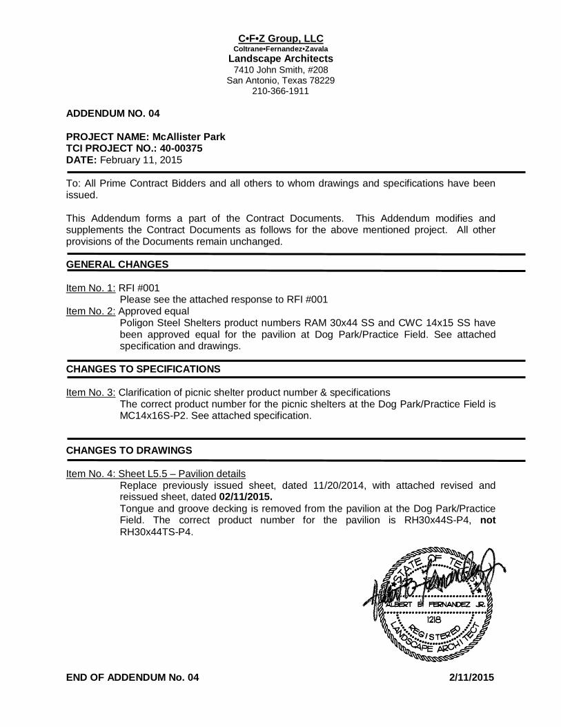
City of San Antonio
TRANSPORTATION AND CAPITAL IMPROVEMENTS
RECEIPT OF ADDENDUM NUMBER(S) 04 IS HEREBY ACKNOWLEDGED FOR PLANS AND
SPECIFICATIONS FOR CONSTRUCTION OF MCALLISTER PARK RENOVATIONS 40-00375
FOR WHICH BIDS WILL BE OPENED ON MARCH 3, 2015
THIS ACKNOWLEDGEMENT MUST BE SIGNED AND RETURNED WITH THE BID PACKAGE. Company Name:
Address:
City/State/Zip Code:
Date:
Signature
Print Name/Title

Addendum No. 04
Attachment 1

McAllister Park Renovations RFI #001 February 11, 2015 ID No. 40‐00375
1. Is there a Geo Report? 6" Lime Treated Sub Grade C‐9.0 ? Response: Geotechnical report has been conducted and is included in this addendum. See
attached. 2. Lime Treated Sub Grade Required? if so no Spec.
Response: See attached specification Item #108 Lime Treated Subgrade.
3. Concrete Creek Crossing L1.6 Note #16 NEW, C7.0 Existing Trail, L2.6 Reconstructed ? Which one is Correct? Response: Disregard note 16 on sheet L1.6. Existing concrete trail at creek crossing is to remain.
Per sheet C‐7.0, gabion mats are to be added on either side of trail.
4. Unit Prices #18 19 20 Fixtures not Part of this Job? No Spec. Response: See updated form 025 Unit Price form issued in Addendum 3, February 6, 2015.
5. Unit Price Note #12 & 21 Same note Drain Box, None Shown on Plans no Detail no Spec? What
do we Price? Response: See updated form 025 Unit Price form issued in Addendum 3, February 6, 2015.
6. Spec 3.73 Separated Contract? 151.311 United States Tax Code ? Texas Sales Tax? This bid looks Lump Some? Response: Regarding clarification for “PREPARATION OF BIDS, Sub Section 3.7.3 Separated
Contract” of the General Conditions Document, the City of San Antonio will provide the contractor with a Tax Exempt certificate that allows the contractor to obtain goods and services for that specific project and only for duration of the construction.
7. Deductive Alternate # 5 Picnic Units 5 Total, We only Find 3 Total?
Response: There are a total of three (3) Picnic Units. All are part of Deductive Alternate #5. See attached updated 020 Bid Form.
8. What is the Trail Repair Additive Alternate #1 & #2 ?
Response: Additive Alternate #1 & #2 will be issued at a later date. Refer to Addendum #3, February 6, 2015.
9. Alternate # 6 Both Parking Areas? Dog Park Parking Lot & Dog Park Practice Field Parking Lot ?
Response: Deductive Alternate #6 includes the location referred to as “Dog Park/Practice Field” in Landscape Drawings (L1, L2, L3, L4 and L5 series). Dog Park Parking Lot (L2.17) is not part of Deductive Alternate #6.

RFI #001 Response
Attachment 1

142 Chula Vista, San Antonio, Texas 78232 • Phone: (210) 308-5884 • Fax: (210) 308-5886
Austin • Corpus Christi • Eagle Pass • Fort Worth • San Antonio
November 17, 2014 Arias Job No. 2014-536 Via Email: [email protected] Mr. Carlos Mendez, AIA City of San Antonio (CoSA) 506 Dolorosa, Suite 103 San Antonio, Texas 78283 RE: Geotechnical Engineering Study (Addendum # 1)
McAllister Park Improvements 13102 Jones Maltsbeger Road San Antonio, Texas
Dear Mr. Mendez:
Arias & Associates, Inc. (ARIAS) is submitting this addendum for the above referenced project located in San Antonio, Texas. Our scope of services was performed in general accordance with our on-call contract for Geotechnical Engineering and Construction Materials Testing between ARIAS and the COSA. The Original Geotechnical study was performed as described in ARIAS Proposal No. 2014-536, (revised September 9, 2014), and was authorized on October 3, 2014 by email authorization from Mr. Arthur M. Rossman at the Office of the City Architect.
ARIAS previously completed the geotechnical study report for this project dated November 3, 2014, to establish pavement and slab on grade foundation design parameters of the subsurface soil and groundwater conditions present at the site for new pavement parking areas, a pavilion structure, and a portable restroom slab for a 1-inch design PVR. At the time of our original report, we were not made aware of the construction of miscellaneous structures such as picnic tables, nor did we provide foundation design requirements for these elements in our original report.
Additionally, this Addendum contains clarification about foundation design parameters for the perimeter beams, and the requirement for the horizontal barrier as described in the report on Page I-3 (Note 9) and on Page II-6 as requested by the Structural Engineer in communication with ARIAS. Therefore, we have been asked to provide this addendum letter with clarification about the foundation design recommendations for the pavilion structure, portable restroom slab, and park tables.
Pavilion Structure
In lieu of utilizing the sheeting and 24” of compacted clay with PI of 15 to 35, the 10’ horizontal barrier could alternately be comprised of 24” of compacted clay with a PI of 40 or greater with no sheeting. However, deletion of the sheeting coupled with use of a higher PI clay means that the Owner must be willing to accept additional risk for increased movements and maintenance over the life of the structure.
Arias & Associates, Inc. 2014-365 Addendum #1
2
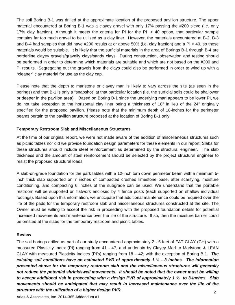
The soil Boring B-1 was drilled at the approximate location of the proposed pavilion structure. The upper material encountered at Boring B-1 was a clayey gravel with only 17% passing the #200 sieve (i.e. only 17% clay fraction). Although it meets the criteria for PI for the PI > 40 option, that particular sample contains far too much gravel to be utilized as a clay liner. However, the materials encountered at B-2, B-3 and B-4 had samples that did have #200 results at or above 50% (i.e. clay fraction) and a PI > 40, so those materials would be suitable. It is likely that the surficial materials in the area of Borings B-1 through B-4 are borderline clayey gravels/gravelly clays/sandy clays. During construction, observation and testing should be performed in order to determine which materials are suitable and which are not based on the #200 and PI results. Segregating out the gravels from the clays could also be performed in order to wind up with a “cleaner” clay material for use as the clay cap. Please note that the depth to marlstone or clayey marl is likely to vary across the site (as seen in the borings) and that B-1 is only a “snapshot” at that particular location (i.e. the surficial soils could be shallower or deeper in the pavilion area). Based on Boring B-1 since the underlying marl appears to be lower PI, we do not take exception to the horizontal clay liner being a thickness of 18” in lieu of the 24” originally specified for the proposed pavilion. Please note that the minimum depth of 18-inches for the perimeter beams pertain to the pavilion structure proposed at the location of Boring B-1 only.
Temporary Restroom Slab and Miscellaneous Structures
At the time of our original report, we were not made aware of the addition of miscellaneous structures such as picnic tables nor did we provide foundation design parameters for these elements in our report. Slabs for these structures should include steel reinforcement as determined by the structural engineer. The slab thickness and the amount of steel reinforcement should be selected by the project structural engineer to resist the proposed structural loads. A slab-on-grade foundation for the park tables with a 12-inch turn down perimeter beam with a minimum 5-inch thick slab supported on 7 inches of compacted crushed limestone base, after scarifying, moisture conditioning, and compacting 6 inches of the subgrade can be used. We understand that the portable restroom will be supported on flatwork enclosed by 4 fence posts (each supported on shallow individual footings). Based upon this information, we anticipate that additional maintenance could be required over the life of the pads for the temporary restroom slab and miscellaneous structures constructed at the site. The Owner must be willing to accept the risk in proceeding with the proposed foundation details for potential increased movements and maintenance over the life of the structure. If so, then the moisture barrier could be omitted at the slabs for the temporary restroom and picnic tables.
Review The soil borings drilled as part of our study encountered approximately 2 - 6 feet of FAT CLAY (CH) with a measured Plasticity Index (PI) ranging from 41 - 47, and underlain by Clayey Marl to Marlstone & LEAN CLAY with measured Plasticity Indices (PI’s) ranging from 18 – 42; with the exception of Boring B-1. The
existing soil conditions have an estimated PVR of approximately 1 ½ - 3 inches. The information
presented above for the temporary restroom slab and the miscellaneous structures will generally
not reduce the potential shrink/swell movements. It should be noted that the owner must be willing
to accept additional risk in proceeding with a design PVR of approximately 1 ½ to 3-inches. Slab
movements should be anticipated that may result in increased maintenance over the life of the
structure with the utilization of a higher design PVR.

ClosingAll other recommendations presented in our original Report not speci ica y addressed herein are still validand should be followed.
It has been a pleasure to provide you this service. Please contact us should you have any questions orneed additional information.
Sincerely,ARIAS & ASSOCIATES, INC.TBP istration No: F-32
WAYNE A. ALLICK, JR.Wayne A. Allick, Jr., P.E Christopher M. Szymczak, P.E.Geotechnical Engineer ~ Senior Geotechnical Engineer
il—~~ -/~‘
Arias & Associates, Inc. 201 4-365 Addendum #1

RFI #001 Response
Attachment 2
142 Chula Vista, San Antonio, Texas 78232 • Phone: (210) 308-5884 • Fax: (210) 308-5886
Austin • Corpus Christi • Eagle Pass • Fort Worth • San Antonio
October 31, 2014 ARIAS Job No. 2014-829 VIA Email: [email protected]
Mr. Arthur Rossman Office of the City Architect Transportation and Capital Improvements (TCI) Municipal Plaza Building 114 Main Plaza Building, 4th Floor, Room 402 San Antonio, Texas 78205
RE: Proposal for Geotechnical Engineering Services Reconstruction of Al Becken Trail McAllister Park Improvements
San Antonio, Texas
Dear Mr. Rossman:
Arias & Associates, Inc. (ARIAS) is pleased to submit this geotechnical study report for the
above referenced project located in San Antonio, Texas. The geotechnical services for this
project were performed as part of the current On Call Contract for Geotechnical Engineering
and Construction Materials Testing Services between the City of San Antonio (CoSA) and
ARIAS. Our scope of services was performed in general accordance with ARIAS Proposal
2014-829, dated October 3, 2014, and was authorized by means of your written approval on
October 6, 2014.
The results provided herein present the various material properties of the existing soils
encountered at our sampling locations near the Al Becken Trail located within McAllister Park in
San Antonio, Texas. ARIAS accessed the site solely for the purpose of conducting soil
sampling for this project on behalf of the City of San Antonio (COSA).
PROJECT DESCRIPTION
As requested by CFZ group, four (4) borings were performed for this project. Our
recommendations are based on the interpreted soil conditions identified by the four (4) borings.
It is our understanding that the geotechnical test results and recommendations will be used by
the COSA and the Design Team in the planning and design to reconstruct the Al Becken Trail at
McAllister Park. Based upon our four (4) borings, it appears that the existing trail consists of
approximately one (1) inch of asphalt pavement with four (4) inches of base material. It is our
understanding that the COSA plans to reconstruct the entire trail, removing the existing
pavement section and replacing it with a new reinforced concrete pavement section.
Arias & Associates, Inc. Page | 2 Job No. 2014-829
ARIAS understands that construction of new light poles supported on drilled piers are also being
considered along the trail. We have provided recommendations herein for the pavement
surface material along the the trail. ARIAS was not contracted to provide any environmental
services or global stability analysis for site slopes or retaining walls. Foundation
recommendations for elements such as light poles, pedestrian bridges, landscape walls, canopy
shade structures, or other project-specific structures have not been included in our scope of
services.
FIELD EXPLORATION
On October 14, 2014, ARIAS and Eagle Drilling, Inc., the drilling subcontractor, were present
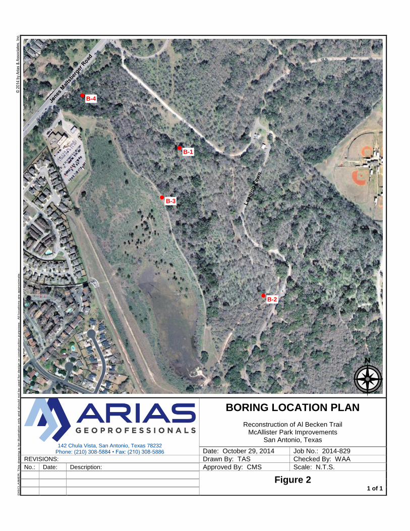
onsite during the performance of four (4) soil borings (B-1 through B-4). The borings were each
drilled to a depth of approximately five (5) feet below the existing ground surface. The soil
borings were performed at the approximate locations shown on the Boring Location Plan
included as Figure 2 in Appendix A.
A truck-mounted drill rig obtained samples with a split-spoon sampler while performing the
Standard Penetration Test (ASTM D 1586), and drilled with a continuous flight auger to advance
and remove soil cuttings from the borehole. Penetration resistance readings were taken on
intact clayey samples recovered in the field with the thin-walled tube sampler. The boreholes
were backfilled with the soil cuttings prior to leaving the site.
The sample depth intervals are shown on the soil boring logs included in Appendix B. ARIAS’
field representative visually logged each recovered sample and placed a portion of the
recovered sampled into a plastic bag and stored them inside a container for transport to our
laboratory. Final soil classifications, as seen on the attached boring logs, were determined in the
laboratory based on laboratory and field test results and applicable ASTM procedures.
LABORATORY TESTING
As a supplement to the field exploration, index laboratory testing was conducted to determine
soil water content, Atterberg Limits, and percent passing the US Standard No. 200 sieve. We
also conducted soluble sulfate concentration testing (Tex-145-E) on subgrade soils up to about
five (5) feet below the surface. The index laboratory test results are reported in the boring logs
included in Appendix B. A key to the terms and symbols used on the logs is also included in
Appendix B. The soil laboratory testing for this project was done in general accordance with
applicable ASTM procedures with the specifications and definitions for these tests listed in
Appendix C. Results of the remaining sample testing are generally shown in Appendix D.
Remaining soil samples recovered from this exploration will be routinely discarded following
submittal of this report.

Arias & Associates, Inc. Page | 3 Job No. 2014-829
SUBSURFACE CONDITIONS Generalized stratigraphy and groundwater conditions encountered are discussed in the
following sections. The subsurface and groundwater conditions are based on conditions
encountered at the boring locations to the depths explored.
Site Stratigraphy and Engineering Properties
The generalized subsurface stratigraphy encountered at this site is summarized in Table 1
below. The presence and thickness of the various subsurface materials can be expected to
vary away from and between the exploration locations. The descriptions generally conform to
the Unified Soils Classification System.
Table 1: Generalized Soil Conditions
Stratum Depth (ft.) Material Type PI
range No. 200 range
N range
I 0 to (2½ - 3)
Clayey Sand w/ Gravel (SC); dark brown to medium dense (only encountered at Boring B-1) FAT CLAY to SANDY FAT CLAY (CH); dark brown, stiff to hard
44 - 63 35 - 95 15 - 38
II (2½ - 3) to 5
Clayey Sand w/ Gravel (SC) to Clayey Gravel with Sand (GC); brown to reddish brown with white, dense to very dense
40 - 55 35 - 49 39 - 54
Where: Depth - Depth from existing ground surface at the time of geotechnical study, feet PI - Plasticity Index, % No. 200 - Percent passing #200 sieve, % N - Standard Penetration Test (SPT) N-value, blows per foot
GROUNDWATER
A dry soil sampling method was used to obtain the soil samples at the project site.
Groundwater was not observed during the sampling activities performed on October 14, 2014.
It should be noted that water levels in open boreholes may require several hours to several days
to stabilize depending on the permeability of the soils. Groundwater levels at the time of
construction may differ from the observations obtained during the field exploration because
perched groundwater is subject to seasonal conditions, recent rainfall, flooding, drought, or
temperature affects. Leaking underground utilities can also impact subsurface water levels.

Arias & Associates, Inc. Page | 4 Job No. 2014-829
Provisions to intercept and divert “perched” or subsurface water should be made if subsurface
water conditions become problematic. Dewatering during construction is considered means and
methods and is solely the responsibility of the Contractor.
TRAIL PAVEMENT DESIGN CONSIDERATIONS
Potential Pavement Distress Due to Expansive Soil Movement
Pavement damage can be significant where expansive soils are present. Several methods exist
for evaluating the swell potential of expansive soils. We have estimated the potential heave for
this site utilizing the TxDOT method (Tex 124-E). Based on this method, we have estimated the
PVR is approximately 4 – 5 inches at this site.
The range of magnitude for heave at the site was estimated considering the moisture content at
the time of the sampling activities. We recommend that site improvements and proper pavement
section design account for these potential soil movement estimations. In the event that
expansive soils are not treated to increase durability of the subgrade, there is a greater potential
for soil movement related to soil shrink-swell.
Our experience indicates that the PVR method can sometimes underestimate the potential
shrink/swell movements. Fluctuations in soil moisture content impacted by climatic conditions or
from development (e.g., irrigation of landscaping in the immediate vicinity of the pavement, poor
surface drainage, or leaking water lines) may result in greater shrink/swell movements than
calculated.
Pavement heaving problems are often associated with the treatment of soils containing high
sulfate concentrations. Heaving causes significant damage to the pavement surface. The
laboratory results indicate that expansive clay is present throughout Borings B-2, B-3, and B-4,
and that high plasticity clayey sand (borderline sandy clay) is present throughout Boring B-1.
The potential pavement damage associated with the shrink-swell properties of near surface
soils should be accounted for in the overall design.
Table 2: Soluble Sulfate Concentration Test Results
Boring No. Approx. Sample Depth
(feet) Sulfate Result (ppm)
B-1 0 - 2 160
B-1 3½ - 5 140
B-2 2 – 3½ 140
B-4 2 – 3½ 140

Arias & Associates, Inc. Page | 5 Job No. 2014-829
The results above are indicative of relatively low soluble sulfate content at this site. Therefore,
lime or cement treatment of the onsite soils can be considered for this site. We recommend
traditional stabilization treatment of the subgrade as prescribed in the TxDOT 2005 Guidelines
for Treatment of Sulfate-Rich Soils and Bases in Pavement Structures. According to the TxDOT
guidelines, sulfate concentrations less than or equal to 3000 ppm pose a low potential for
sulfate heave. This treatment approach minimizes sulfate induced heave associated with
chemical reactions when calcium based additives are used to treat subgrade soils that contain
sulfate/sulfide minerals. Our scope of work did not include material mix design testing to
determine the optimum lime content for treatment of the subgrade. However, soil-additive mix
design and construction standards are specified in TxDOT’s 2004 Standard Specifications for
Construction and Maintenance of Highways, Streets, and Bridges.
Effect of Trees and Vegetation
Soil moisture can be affected by the roots of vegetation that extend beneath pavements. Trees
remove large quantities of water from the soil through their root systems during the growing
season and cause localized drier areas in the vicinity of the roots. The limits of affected areas
are typically related to the lateral extent of a root system, which are a function of the tree height
and the spread of its branches. It is generally accepted that a root system will influence the soil
moisture levels to a distance roughly equivalent to the drip line (extent of branches).
Pavements constructed over a tree root system may shrink due to changes in moisture content
and result in cracking. These types of movements result in concentric crack patterns in street
pavements located near trees.
Pavement Parameters and Conditions
Traffic counts for various vehicle types traversing the trail have not been provided. Accordingly,
we have assumed that the trail will handle primarily pedestrian and bicycle traffic and possibly
an occasional automobile or light duty pickup. Therefore, we have assumed the design traffic to
be equal to or less than 25,000 equivalent single axle loads (ESALs). If any of these
assumptions are incorrect, we should be contacted in order to review and revise our
recommendations accordingly.

Arias & Associates, Inc. Page | 6 Job No. 2014-829
Pavement Sections
We are aware that the CoSA intends to use a reinforced concrete pavement surface for the
proposed trail. Given the potential movements noted above, we recommend conditioning of any
untreated expansive subgrade soils along the trail with a Plasticity Index greater than 15 (PI >
15). The pavement surface material recommendations given subsequently are intended to
handle pedestrian, bicycle and infrequent light duty motorized vehicle use on the pavement. We
anticipate that substantial maintenance would be required over the life of pavements at this site,
particularly where significant post-construction total and differential movements occur. We have
based our recommendation on the expectation of recreational use of the trail. Should alternate
or more stringent requirements be desired, we should be contacted to provide additional
recommendations.
Table 3: Recommended Pavement Section
Layer Material
Thickness
Concrete Pavement Portland Cement Concrete 5”
Base Material Crushed Limestone Flexible
Base - TxDOT Item 247, Type A, Grade 1 or 2
6”
Subgrade Lime Treatment
See NOTES: 1 & 2 6”
NOTES:
1. Pavements founded on top of clayey soils will be subject to PVR soil movements
estimated and presented in this report (i.e., about 4 to 5 inches). These potential soil
movements are typically activated to some degree during the life of the pavement.
Consequently, pavements can be expected to crack and require periodic maintenance.
Periodic/preventative maintenance and repair should be planned for to reduce
deterioration of the pavement structure while aiding to preserve the investment.
2. The exposed subgrade materials should be tested for soluble sulfate content before
using the lime treatment as an option.
We recommend placing at least 5 inches of reinforced concrete to surface the pathway. We also
advise that site preparation and subgrade compaction should be performed in accordance with
our recommendations. The actual performance life of concrete pavement material will be
dependent upon providing routine maintenance, as well as, application of repair material in the
future.

Arias & Associates, Inc. Page | 7 Job No. 2014-829
Rigid Concrete Pavement Joints
Placement of expansion joints in concrete paving on potentially expansive subgrade or on
granular subgrade subject to piping often results in horizontal and vertical movement at the joint.
Many times, concrete spalls adjacent to the joint and eventually a failed concrete area results.
This problem is primarily related to water infiltration through the joint.
One method to mitigate the problem of water infiltration through the joints is to eliminate all
expansion joints that are not absolutely necessary. It is our opinion that expansion or isolation
joints are needed only adjacent where the pavement abuts intersecting drive lanes and other
structures. Elimination of all expansion joints within the main body of the pavement area would
significantly reduce access of moisture into the subgrade. Regardless of the type of expansion
joint sealant used, eventually openings in the sealant occur resulting in water infiltration into the
subgrade.
The use of sawed and sealed joints should be designed in accordance with current Portland
Cement Association (PCA) or American Concrete Institute (ACI) guidelines. Research has
proven that joint design and layout can have a significant effect on the overall performance of
concrete pavement.
Recommendations presented herein are based on the use of reinforced concrete pavement.
Local experience has shown that the use of distributed steel placed at a distance of 1/3 slab
thickness from the top is of benefit in crack control for concrete pavements. Improved crack
control also reduces the potential for water infiltration.
The concrete pavement should include as a minimum the following:
Reinforcing Steel - #4 @ 16” each way placed D/3 from top of slab
Construction Joint Dowels ⅝” diameter for 5” pavement, 14” long @ 12” on-center,
lubricated both sides @ mid depth
Maximum Control Joint Spacing 10 feet or less
Control Joint Depth – D/4 from top
Min. 28 day compressive strength – 3,500 psi
A monolithically-poured, reinforced turn down beam at all edges penetrating through the
flexible base and at least 3 inches into the underlying clay
6-inch lime treated subgrade
6-inches of compacted crushed limestone flexible base (8 inches if geogrid is substituted
for lime treatment)
Performance Considerations
Our pavement recommendations have been developed to provide an adequate structural
thickness to support the anticipated traffic volumes. Some shrink/swell movements due to
moisture variations in the underlying soils, or potential movement from settling utility backfill
Arias & Associates, Inc. Page | 8 Job No. 2014-829
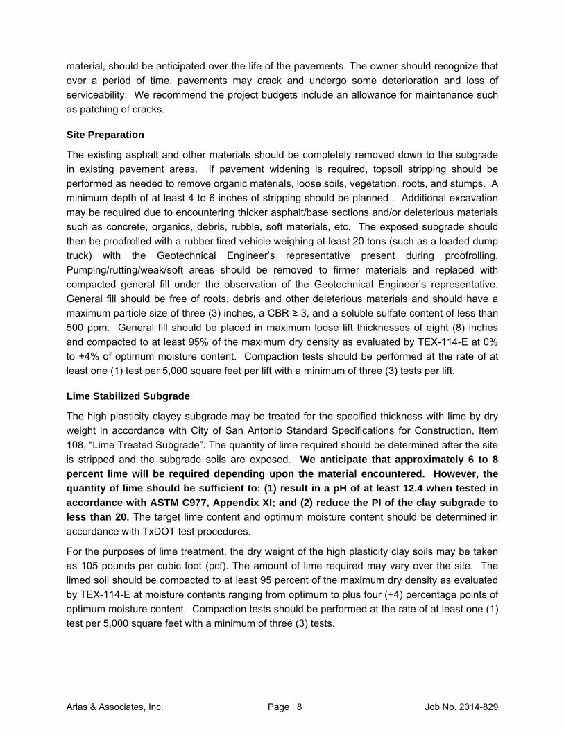
material, should be anticipated over the life of the pavements. The owner should recognize that
over a period of time, pavements may crack and undergo some deterioration and loss of
serviceability. We recommend the project budgets include an allowance for maintenance such
as patching of cracks.
Site Preparation
The existing asphalt and other materials should be completely removed down to the subgrade
in existing pavement areas. If pavement widening is required, topsoil stripping should be
performed as needed to remove organic materials, loose soils, vegetation, roots, and stumps. A
minimum depth of at least 4 to 6 inches of stripping should be planned . Additional excavation
may be required due to encountering thicker asphalt/base sections and/or deleterious materials
such as concrete, organics, debris, rubble, soft materials, etc. The exposed subgrade should
then be proofrolled with a rubber tired vehicle weighing at least 20 tons (such as a loaded dump
truck) with the Geotechnical Engineer’s representative present during proofrolling.
Pumping/rutting/weak/soft areas should be removed to firmer materials and replaced with
compacted general fill under the observation of the Geotechnical Engineer’s representative.
General fill should be free of roots, debris and other deleterious materials and should have a
maximum particle size of three (3) inches, a CBR ≥ 3, and a soluble sulfate content of less than
500 ppm. General fill should be placed in maximum loose lift thicknesses of eight (8) inches
and compacted to at least 95% of the maximum dry density as evaluated by TEX-114-E at 0%
to +4% of optimum moisture content. Compaction tests should be performed at the rate of at
least one (1) test per 5,000 square feet per lift with a minimum of three (3) tests per lift.
Lime Stabilized Subgrade
The high plasticity clayey subgrade may be treated for the specified thickness with lime by dry
weight in accordance with City of San Antonio Standard Specifications for Construction, Item
108, “Lime Treated Subgrade”. The quantity of lime required should be determined after the site
is stripped and the subgrade soils are exposed. We anticipate that approximately 6 to 8 percent lime will be required depending upon the material encountered. However, the quantity of lime should be sufficient to: (1) result in a pH of at least 12.4 when tested in accordance with ASTM C977, Appendix XI; and (2) reduce the PI of the clay subgrade to less than 20. The target lime content and optimum moisture content should be determined in
accordance with TxDOT test procedures.
For the purposes of lime treatment, the dry weight of the high plasticity clay soils may be taken
as 105 pounds per cubic foot (pcf). The amount of lime required may vary over the site. The
limed soil should be compacted to at least 95 percent of the maximum dry density as evaluated
by TEX-114-E at moisture contents ranging from optimum to plus four (+4) percentage points of
optimum moisture content. Compaction tests should be performed at the rate of at least one (1)
test per 5,000 square feet with a minimum of three (3) tests.

Arias & Associates, Inc. Page | 9 Job No. 2014-829
Flexible Base Material
Flexible base material should conform to TxDOT Item 247, Type A, Grade 1 or 2, and should be
placed in maximum loose lift thicknesses of eight (8) inches and compacted to at least 95% of
the maximum dry density as evaluated by TEX-113-E at -1% to +3% of optimum moisture
content. Compaction tests should be performed at the rate of at least one (1) test per 5,000
square feet per lift with a minimum of three (3) tests per lift.
Drainage Good positive drainage during and after construction is very important to reduce expansive soil
volume changes that can detrimentally affect the performance of the planned development.
Proper attention to surface and subsurface drainage details during the design and construction
phase of development can aid in preventing many potential soil shrink-swell related problems
GENERAL COMMENTS The scope of this study is to provide geotechnical engineering criteria for use by design
engineers in preparing the pavement design for the pedestrian trail. Environmental and stability
studies of any kind were not a part of our scope of work or services.
This report was prepared as an instrument of service for this project exclusively for the use of
the City of San Antonio TCI and the project design team. If the development plans change
relative to overall site layout, size, or anticipated pavement loads or if different subsurface
conditions are encountered, we should be informed and retained to ascertain the impact of
these changes on our recommendations. We cannot be responsible for the potential impact of
these changes if we are not informed.
SUBSURFACE VARIATIONS
Soil and groundwater conditions may vary away from the sample boring locations. Transition
boundaries or contacts, noted on the boring logs to separate soil types, are approximate.
Actual contacts may be gradual and vary at different locations. The contractor should verify that
similar conditions exist throughout the proposed area of excavation. If different subsurface
conditions or highly variable subsurface conditions are encountered during construction, we
should be contacted to evaluate the significance of the changed conditions relative
to our recommendations.
QUALITY ASSURANCE TESTING
The long-term success of the project will be affected by the quality of materials used for
construction and the adherence of the construction to the project plans and specifications. As
Geotechnical Engineer of Record (GER), we should be engaged by the Owner to provide
Quality Assurance (QA) testing. Our services will be to evaluate the degree to which
constructors are achieving the specified conditions they’re contractually obligated to achieve,
and observe that the encountered materials during earthwork for foundation and pavement

Arias & Associates, Inc. Page | 10 Job No. 2014-829
installation are consistent with those encountered during this study. In the event that ARIAS is
not retained to provide QA testing, we should be immediately contacted if differing subsurface
conditions are encountered during construction. Differing materials may require modification to
the recommendations that we provided herein. A message to the Owner with regard to the
project QA is provided in the ASFE publication included in Appendix F.
ARIAS has an established in-house laboratory that meets the standards of the American
Standard Testing Materials (ASTM) specifications of ASTM E-329 defining requirements for
Inspection and Testing Agencies for soil, concrete, steel and bituminous materials as used in
construction. We maintain soils, concrete, asphalt, and aggregate testing equipment to provide
the testing needs required by the project specifications. All of our equipment is calibrated by an
independent testing agency in accordance with the National Bureau of Standards. In addition,
ARIAS is accredited by the American Association of State Highway & Transportation Officials
(AASHTO), the United States Army Corps of Engineers (USACE) and the Texas Department of
Transportation (TxDOT), and also maintains AASHTO Materials Reference Laboratory (AMRL)
and Cement and Concrete Reference Laboratory (CCRL) proficiency sampling, assessments
and inspections. Furthermore, ARIAS employs a technical staff certified through the following
agencies: the National Institute for Certification in Engineering Technologies (NICET), the
American Concrete Institute (ACI), the American Welding Society (AWS), the
Precast/Prestressed Concrete Institute (PCI), the Mine & Safety Health Administration (MSHA),
the Texas Asphalt Pavement Association (TXAPA) and the Texas Board of Professional
Engineers (TBPE).
STANDARD OF CARE
Subject to the limitations inherent in the agreed scope of services as to the degree of care and
amount of time and expenses to be incurred, and subject to any other limitations contained in
the agreement for this work, ARIAS has performed its services consistent with that level of care
and skill ordinarily exercised by other professional engineers practicing in the same locale and
under similar circumstances at the time the services were performed.
Information about this geotechnical report is provided in the ASFE publication included in
Appendix E.
We look forward to working with the Project Design Team as additional geotechnical and/or
construction materials testing needs develop.
Please let us know if you have any questions. We greatly appreciate the opportunity to be of
service to you.
Cordially,
ARIAS & Associates, Inc.

TBPE Registration No. F-32
/ /
iWa ~eAIIick .,P.E.Geotechnical Engineer
Attachments:FiguresBoring Logs and Key to TermsLaboratory and Field Test ProceduresLaboratory Test ResultsASFE Information — Geotechnical ReportProject Quality Assurance
/~)— 3/—/~
Senior Geotechnical Engineer
Arias & Associates, Inc. Page III Job No. 2014-829

APPENDIX A: FIGURES

142 Chula Vista, San Antonio, Texas 78232 Phone: (210) 308-5884 • Fax: (210) 308-5886
VICINITY MAP
Reconstruction of Al Becken Trail McAllister Park Improvements
San Antonio, Texas
Date: October 29, 2014 Job No.: 2014-829 Figure 1
1 of 1 Drawn By: TAS Checked By: WAA
Approved By: CMS Scale: N.T.S.
Approximate Site Location
142 Chula Vista, San Antonio, Texas 78232 Phone: (210) 308-5884 • Fax: (210) 308-5886
BORING LOCATION PLAN
Reconstruction of Al Becken Trail McAllister Park Improvements
San Antonio, Texas
Date: October 29, 2014 Job No.: 2014-829 REVISIONS: Drawn By: TAS Checked By: WAA
No.: Date: Description: Approved By: CMS Scale: N.T.S.
Figure 2
1 of 1
B-2
B-1
B-3
B-4

Photo 1 – Approximate location of Boring B-1.
Photo 2 – Approximate location of Boring B-2.
142 Chula Vista, San Antonio, Texas 78232 Phone: (210) 308-5884 • Fax: (210) 308-5886
SITE PHOTOS
Reconstruction of Al Becken Trail McAllister Park Improvements
San Antonio, Texas
Date: October 29, 2014 Job No.: 2014-829 Appendix A
1 of 2 Drawn By: TAS Checked By: WAA
Approved By: CMS Scale: N.T.S.

Photo 3 – Approximate location of Boring B-3.
Photo 4 – Approximate location of Boring B-4.
142 Chula Vista, San Antonio, Texas 78232 Phone: (210) 308-5884 • Fax: (210) 308-5886
SITE PHOTOS
Reconstruction of Al Becken Trail McAllister Park Improvements
San Antonio, Texas
Date: October 29, 2014 Job No.: 2014-829 Appendix A
2 of 2 Drawn By: TAS Checked By: WAA
Approved By: CMS Scale: N.T.S.
APPENDIX B: BORING LOGS AND KEY TO TERMS

ASPHALT, 1-inchesBASE, 4-inches
CLAYEY SAND with Gravel (SC), medium dense, dark brown
Dense below 2.5'
CLAYEY SAND with Gravel (SC), dense, reddish brown with white
Borehole terminated at 5 feet
35
36
20
31
43
20
22
64
62
44
40
14
2
7
GB
SS
SS
SS
Location: See Boring Location Plan
Coordinates: N29o33'34.4'' W98o27'22.6''
Boring Log No. B-1
Groundwater Data:During drilling: Not encountered
Field Drilling Data:Coordinates: Hand-held GPS UnitLogged By: R. ArizolaDriller: Eagle Drilling, Inc.Equipment: Truck-mounted drill rig
WC = Water Content (%)PL = Plastic LimitLL = Liquid LimitPI = Plasticity IndexN = SPT Blow Count
-200 = % Passing #200 Sieve
Single flight auger: 0 - 5 ft
Soil Description
Nomenclature Used on Boring Log
Arias & Associates, Inc.
Backfill: Cuttings
Grab Sample (GB) Split Spoon (SS)
Job No.: 2014-829
Project: Reconstruction of Al Becken TrailMcAllister Park ImprovementsSan Antonio, Texas
Sampling Date: 10/14/14
2014
-829
.GP
J 10
/31
/14
(BO
RIN
G L
OG
SA
13-0
2,A
RIA
SS
A12
-01.
GD
T,L
IBR
AR
Y20
13-0
1.G
LB)
-200NPL LL PIWCSNDepth(ft)
1
2
3
4
5

ASPHALT, 1-inchBASE, 4-inches
FAT CLAY (CH), stiff, dark brown
CLAYEY GRAVEL with Sand (GC), dense, reddish brown withwhite
Very dense below 4'
Borehole terminated at 5 feet
95
26
16
15
42
5425 80 55
18
10
5
GB
SS
SS
SS
Location: See Boring Location Plan
Coordinates: N29o33'21.4'' W98o27'14.2''
Boring Log No. B-2
Groundwater Data:During drilling: Not encountered
Field Drilling Data:Coordinates: Hand-held GPS UnitLogged By: R. ArizolaDriller: Eagle Drilling, Inc.Equipment: Truck-mounted drill rig
WC = Water Content (%)PL = Plastic LimitLL = Liquid LimitPI = Plasticity IndexN = SPT Blow Count
-200 = % Passing #200 Sieve
Single flight auger: 0 - 5 ft
Soil Description
Nomenclature Used on Boring Log
Arias & Associates, Inc.
Backfill: Cuttings
Grab Sample (GB) Split Spoon (SS)
Job No.: 2014-829
Project: Reconstruction of Al Becken TrailMcAllister Park ImprovementsSan Antonio, Texas
Sampling Date: 10/14/14
2014
-829
.GP
J 10
/31
/14
(BO
RIN
G L
OG
SA
13-0
2,A
RIA
SS
A12
-01.
GD
T,L
IBR
AR
Y20
13-0
1.G
LB)
-200NPL LL PIWCSNDepth(ft)
1
2
3
4
5
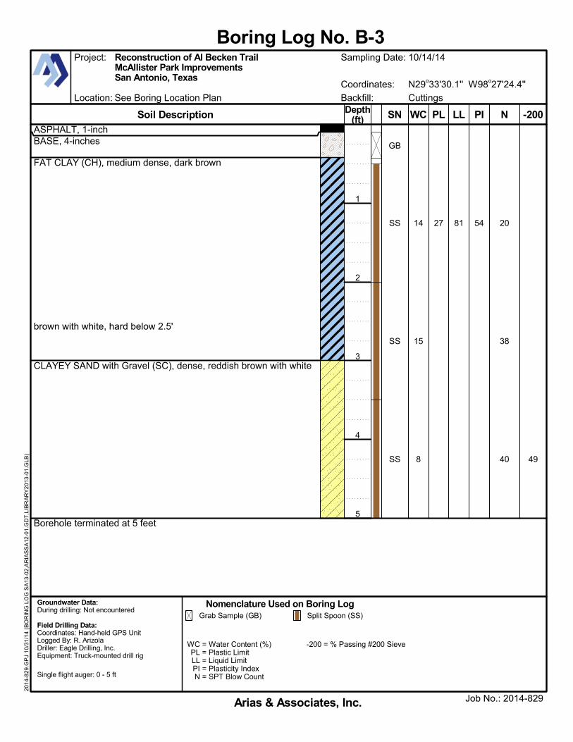
ASPHALT, 1-inchBASE, 4-inches
FAT CLAY (CH), medium dense, dark brown
brown with white, hard below 2.5'
CLAYEY SAND with Gravel (SC), dense, reddish brown with white
Borehole terminated at 5 feet
49
20
38
40
27 81 5414
15
8
GB
SS
SS
SS
Location: See Boring Location Plan
Coordinates: N29o33'30.1'' W98o27'24.4''
Boring Log No. B-3
Groundwater Data:During drilling: Not encountered
Field Drilling Data:Coordinates: Hand-held GPS UnitLogged By: R. ArizolaDriller: Eagle Drilling, Inc.Equipment: Truck-mounted drill rig
WC = Water Content (%)PL = Plastic LimitLL = Liquid LimitPI = Plasticity IndexN = SPT Blow Count
-200 = % Passing #200 Sieve
Single flight auger: 0 - 5 ft
Soil Description
Nomenclature Used on Boring Log
Arias & Associates, Inc.
Backfill: Cuttings
Grab Sample (GB) Split Spoon (SS)
Job No.: 2014-829
Project: Reconstruction of Al Becken TrailMcAllister Park ImprovementsSan Antonio, Texas
Sampling Date: 10/14/14
2014
-829
.GP
J 10
/31
/14
(BO
RIN
G L
OG
SA
13-0
2,A
RIA
SS
A12
-01.
GD
T,L
IBR
AR
Y20
13-0
1.G
LB)
-200NPL LL PIWCSNDepth(ft)
1
2
3
4
5

ASPHALT, 1-inchBASE, 4-inches
SANDY FAT CLAY (CH), hard, dark brown
CLAYEY SAND (SC) with gravel, dense, brown with white
Borehole terminated at 5 feet
54
35
27
39
39
27
21
90
61
63
40
20
10
7
GB
SS
SS
SS
Location: See Boring Location Plan
Coordinates: N29o33'39.1'' W98o27'32.3''
Boring Log No. B-4
Groundwater Data:During drilling: Not encountered
Field Drilling Data:Coordinates: Hand-held GPS UnitLogged By: R. ArizolaDriller: Eagle Drilling, Inc.Equipment: Truck-mounted drill rig
WC = Water Content (%)PL = Plastic LimitLL = Liquid LimitPI = Plasticity IndexN = SPT Blow Count
-200 = % Passing #200 Sieve
Single flight auger: 0 - 5 ft
Soil Description
Nomenclature Used on Boring Log
Arias & Associates, Inc.
Backfill: Cuttings
Grab Sample (GB) Split Spoon (SS)
Job No.: 2014-829
Project: Reconstruction of Al Becken TrailMcAllister Park ImprovementsSan Antonio, Texas
Sampling Date: 10/14/14
2014
-829
.GP
J 10
/31
/14
(BO
RIN
G L
OG
SA
13-0
2,A
RIA
SS
A12
-01.
GD
T,L
IBR
AR
Y20
13-0
1.G
LB)
-200NPL LL PIWCSNDepth(ft)
1
2
3
4
5

GW
GP
GM
GC
SW
SP
SM
SC
ML
CL
MH
CH
Very Stiff
Hard
4 - 8
8 - 15
15 - 30
Over 30
Below 2
2 - 4 Soft
Very Soft
Stiff
Less than 0.25
0.25 - 0.5
0.5 - 1.0
1.0 - 2.0
Over 4.0
2.0 - 4.0
Medium (Firm)
Density of Granular Soils
Relative Density
Very Loose
Number of Blows per ft.,
N
0 - 4
4 - 10 Loose
Medium
Dense
Very Dense
30 - 50
Over 50
10 - 30
Consistency and Strength of Cohesive Soils
Number of Blows per ft., N
Unconfined Compressive
Strength, qᵤ (tsf)Consistency
Clayey Gravels, Gravel-Sand-Clay Mixtures
Massive Sandstones, Sandstones with Gravel Clasts
Inorganic Clays of High Plasticity, Fat Clays
Inorganic Silts, Micaceous or Diatomaceous Fine Sand or Silty Soils, Elastic Silts
Inorganic Clays of Low to Medium Plasticity, Gravelly Clays, Sandy Clays, Silty Clays, Lean Clays
Inorganic Silts & Very Fine Sands, Rock Flour, Silty or Clayey Fine Sands or Clayey Silts with Slight Plasticity
Indurated Argillaceous Limestones
Indicates Final Observed Groundwater Level
Indicates Initial Observed Groundwater Location
Cretaceous Clay Deposits
Massive or Poorly Bedded Chalk Deposits
Mudstone or Massive Claystones
GIN
E-G
RA
IND
SO
ILS
Mor
e th
an h
alf o
f Coa
rse
frac
tion
is
SM
ALL
ER
than
No.
4 S
ieve
siz
e
SILT
S &
C
LAYS
SILT
S &
C
LAYS
Cle
an G
rave
ls
(littl
e or
no
Fin
es)
Gra
vels
with
F
ines
(A
ppre
ciab
le
amou
nt o
f Fin
es)
Cle
an S
ands
(lit
tle
or n
o F
ines
)
San
ds w
ith F
ines
(A
ppre
ciab
le
amou
nt o
f Fin
es)
Liqu
id L
imit
less
th
an 5
0Li
quid
Lim
it gr
eate
r th
an 5
0
LIMESTONE
MARLSTONE
SANDSTONE
GROUNDWATER
MARINE CLAYS
CHALK
CLAYSTONE
GROUP SYMBOLS
KEY TO TERMS AND SYMBOLS USED ON BORING LOGS
CO
AR
SE-G
RA
IND
SO
ILS
GR
AVE
LSSA
ND
S
Mor
e th
an H
alf o
f Coa
rse
frac
tion
is
LAR
GE
R th
an N
o. 4
Sie
ve s
ize
Mor
e th
an h
alf o
f mat
eria
l LA
RG
ER
than
No.
200
Sie
ve s
ize
MAJOR DIVISIONS
Silty Gravels, Gravel-Sand-Silt Mixtures
Poorly-Graded Gravels, Gravel-Sand Mixtures, Little or no Fines
Well-Graded Gravels, Gravel-Sand Mixtures, Little or no Fines
DESCRIPTIONS
Clayey Sands, Sand-Clay Mixtures
Silty Sands, Sand-Silt Mixtures
Poorly-Graded Sands, Gravelly Sands, Little or no Fines
Well-Graded Sands, Gravelly Sands, Little or no Fines
Massive or Weakly Bedded Limestones
Mor
e th
an h
alf o
f mat
eria
l SM
ALL
ER
th
an N
o. 2
00 S
ieve
siz
e
FOR
MA
TIO
NA
L M
ATE
RIA
LS
Arias and Associates, Inc.

Group Symbol
GW(Less than 5% finesC )
Cu < 4 and/or GP
[Cc < or Cc > 3]D
Gravels with Fines GM
(More than 12% finesC )GC
Sands Clean Sands SW
(Less than 5% finesH ) Cu < 6 and/or SP
[Cc < or Cc > 3]D
Sands with Fines SM
(More than 12% finesH )SC
Silts and Clays inorganic CL
ML
organic Liquid limit - oven dried/Liquid & #10 OL< 0.75
Silts and Clays inorganic CH
MH
organic Liquid limit - oven dried/Liquid & #10 OH< 0.75
HIGHLY ORGANIC SOILS PTA Based on the material passing the 3-inch (75mm) sieveB If field sample contained cobbles or boulders, or both, add "with cobbles or boulders, or both" to group name
C Gravels with 5% to 12% fines require dual symbols:GW-GM well-graded gravel with siltGW-GC well-graded gravel with clayGP-GM poorly-graded gravel with siltGP-GC poorly-graded gravel with clay
D Cu = D60/D10 Cc =
E If soil contains ≥ 15% sand, add "with sand" to group nameF If fines classify as CL-ML, use dual symbol GC-GM, or SC-SMG If fines are organic, add "with organic fines" to group nameH Sand with 5% to 12% fines require dual symbols:
SW-SM well-graded sand with siltSW-SC well-graded sand with claySP-SM poorly-graded sand with siltSP-SC poorly-graded sand with clay
I If soil contains ≥ 15% gravel, add "with gravel" to group nameJ If Atterberg limits plot in hatched area, soil is a CL-ML, silty clayK If soil contains 15% to < 30% plus No. 200, add "with sand" or "with gravel," whichever is predominantL If soil contains ≥ 30% plus No. 200, predominantly sand, add "sandy" to group nameM If soil contains ≥ 30% plus No. 200, predominantly gravel, add "gravelly" to group nameN PI ≥ 4 and plots on or above "A" lineO PI < 4 or plots below "A" lineP PI plots on or above "A" lineQ PI plots below "A" line
TERMINOLOGY
Boulders Over 12-inches (300mm) Parting Inclusion < 1/8-inch thick extending through samples
Cobbles 12-inches to 3-inches (300mm to 75mm) Seam Inclusion 1/8-inch to 3-inches thick extending through sample
Gravel 3-inches to No. 4 sieve (75mm to 4.75mm) Layer Inclusion > 3-inches thick extending through sample
Sand No. 4 sieve to No. 200 sieve (4.75mm to 0.075mm)
Silt or Clay Passing No. 200 sieve (0.075mm)
Calcareous Containing appreciable quantities of calcium carbonate, generally nodular
Stratified Alternating layers of varying material or color with layers at least 6mm thick
Laminated Alternating layers of varying material or color with the layers less than 6mm thick
Fissured Breaks along definite planes of fracture with little resistance to fracturing
Slickensided Fracture planes appear polished or glossy sometimes striated
Blocky Cohesive soil that can be broken down into small angular lumps which resist further breakdown
Lensed Inclusion of small pockets of different soils, such as small lenses of sand scattered through a mass of clay
Homogeneous Same color and appearance throughout
Fines classify as CL or CH
Cu ≥ 6 and 1 ≤ Cc ≤ 3D
Soil ClassificationCriteria of Assigning Group Symbols and Group Names Using Laboratory TestsA
More than 50% retained on No. 200 sieve
FINE-GRAINED SOILS
COARSE-GRAIND SOILS
Primarily organic matter, dark in color, and organic odor
Liquid limit less than 50
Liquid limit 50 or more
PI > 7 and plots on or
above "A" lineJ
PI < 4 or plots below "A"
lineJ
PI plots on or above "A" line
PI plots on or above "A" line
Fines classify as CL or CH
(50% or more of coarse fraction passes No. 4 sieve)
50% or more passes the No. 200 sieve
Cu ≥ 4 and 1 ≤ Cc ≤ 3DGravels Clean Gravels
Elastic SiltK,L,M
Organic ClayK,L,M,P
Organic SiltK,L,M,Q
Peat
Lean ClayK,L,M
SiltK,L,M
Organic ClayK,L,M,N
Organi SiltK,L,M,O
Fat ClayK,L,M
Clayey GravelE,F,G
Well-Graded SandI
Poorly-Graded SandI
Silty SandF,G,I
Clayey SandF,G,I
Well-Graded GravelE
Poorly-Graded GravelE
Silty GravelE,F,GFines classify as ML or MH
(More than 50% of coarse fraction retained on No. 4 sieve)
Fines classify as ML or MH
KEY TO TERMS AND SYMBOLS USED ON BORING LOGS
TABLE 1 Soil Classification Chart (ASTM D 2487-11)
Group NameB
(D30)2
D10 x D60
Arias and Associates, Inc.

KEY TO TERMS AND SYMBOLS USED ON BORING LOGS
Hardness Classification of Intact Rock
Rock Weathering Classifications
Rock Discontinuity Spacing
Engineering Classification for in Situ Rock Quality
Class
I
II
III
IV
V
Extremely hard
Hardness
Very hard
Hard
Soft
Very soft
Less than ¼ inch
¾ – 2½ inches
2½ – 8 inches
8 – 24 inches
Grade
Fresh
Slightly Weathered
Moderately Weathered
Highly Weathered
Completely Weathered
Residual Soil
Description for Structural Features: Bedding, Foliation, or Flow Banding
Very thickly (bedded, foliated, or banded)
Symbol
F
WS
WM
WH
WC
RS
More than 6 feet
Thickly
Medium
Thinly
Very thinly
Description for Micro-Structural Features: Lamination, Foliation, or
Cleavage
Intensely (laminated, foliated, or cleaved)
Very intensely
Spacing
¼ – ¾ inch
2 – 6 feet
Very widely (fractured or jointed)
Widely
Medium
Closely
Very closely
Descriptions for Joints, Faults, or Other Fractures
Extremely close
Diagnostic Features
No visible sign of Decomposition or discoloration. Rings under hammer impact.
Slight discoloration inwards from open fractures, otherwise similar to F.
Discoloration throughout. Weaker minerals such as feldspar decomposed. Strength somewhat less than fresh rock, but cores cannot be broken by hand or scraped by knife.
Texture preserved.
Most minerals somewhat decomposed. Specimens can be broken by hand with effort or shaved with knife. Core stones present in rock mass. Texture becoming indistinct, but fabric
preserved.
Minerals decomposed to soil, but fabric and structure preserved (Saprolite). Specimens easily crumbled or penetrated.
Advanced state of decomposition resulting in plastic soils. Rock fabric and structure completely destroyed. Large volume change.
Spacing Description for Joints, Faults or Other Fractures
Excellent
Rock Mass QualityVelocity IndexRQD %
90 – 100
75 – 90
50 – 75
25 – 50
0 – 25
0.80 – 1.00
0.60 – 0.80
0.40 – 0.60
0.20 – 0.40
0 – 0.20
Good
Fair
Very Poor
Poor
> 2,000
Approximate Range of Uniaxial Compression Strength kg/cm²
(tons/ft²)
2,000 – 1,000
1,000 – 500
500 – 250
250 – 10
Field Test
Many blows with geologic hammer required to break intact specimen.
Hand held specimen breaks with hammer end of pick under more than one blow.
Cannot be scraped or pealed with knife, hand held specimen can be broken with single moderate blow with pick.
Can just be scraped or peeled with knife. Indentations 1mm to 3mm show in specimen with moderate blow with pick.
Material crumbles under moderate blow with sharp end of pick and can be peeled with a knife, but is too hard to hand-trim for triaxial test specimen.
Arias and Associates, Inc.

APPENDIX C: LABORATORY AND FIELD TEST PROCEDURES

FIELD AND LABORATORY EXPLORATION
The field exploration program included drilling at selected locations within the site and
intermittently sampling the encountered materials. The boreholes were drilled using single flight
auger (ASTM D 1452). Samples of encountered material were generally obtained using a split-
spoon sampler (ASTM D1586) or by taking material from the auger as it was advanced (ASTM
D 1452). The sample depth interval and type of sampler used is included on the soil boring
logs. ARIAS’ field representative visually logged each recovered sample and placed a portion
of the recovered sampled into a plastic bag for transport to our laboratory. N-values for SPT
samples are shown on the soil boring logs.
ARIAS performed soil mechanics laboratory tests on selected samples to aid in soil
classification and to determine engineering properties. Tests commonly used in geotechnical
exploration, the method used to perform the test, and the column designations on the boring log
where data are reported are summarized as follows:
Test Name Test Method Log Designation Water (moisture) content of soil and rock by mass ASTM D 2216 WC
Liquid limit, plastic limit, and plasticity index of soils ASTM D 4318 PL, LL, PI
Amount of material in soils finer than the No. 200 sieve ASTM D 1140 -200
Particle size analysis of soils (with or without fines
fraction)
ASTM D 422 -200
The laboratory results are reported on the soil boring logs.

APPENDIX D: LABORATORY TEST RESULTS

0
5
10
15
20
25
30
35
40
45
50
55
60
65
70
75
80
85
90
95
100
0.0010.010.1110100
Depth
1.5
medium
6 810 14
Classification
503/4 1/23/8
Boring
Boring Depth
GRAIN SIZE DISTRIBUTION
Arias & Associates, Inc.
COBBLESGRAVEL SAND
PI Cc
HYDROMETERU.S. SIEVE OPENING IN INCHES U.S. SIEVE NUMBERS
D100 D60
CuLL PL
GRAIN SIZE IN MILLIMETERS
PE
RC
EN
T F
INE
R B
Y W
EIG
HT
coarse
3
%Gravel %Sand %Silt %Clay
100 1403 2
D10
4
fine coarseSILT OR CLAY
4
D30
0.5
3.5
0.5
2.0
1
1
2
2
20016 20 30 4016 60
fine
Elev
1
1
2
2
CLAYEY SAND with GRAVEL (SC)
CLAYEY SAND with GRAVEL (SC)
64
62
20
22
44
40
1.147
0.983
3.098 0.193
20.9
18.7
1.6
34.3
35.1
36.1
95.3
25.8
Silt and clay fractions were determined using 0.002 mm as the maximum particle size for clay.
0.5
3.5
0.5
2.0
75
75
75
75
44.0
45.2
3.1
39.9
Project: Reconstruction of Al Becken Trail
Location: See Boring Location Plan
Job No.: 2014-829
2014
-829
.GP
J 10
/31
/14
(GR
AIN
SIZ
E A
RIA
S,U
S_L
AB
.GD
T,L
IBR
AR
Y20
13-0
1.G
LB)
142 Chula VistaSan Antonio, Texas 78232Phone: (210) 308-5884Fax: (210) 308-5886
0
5
10
15
20
25
30
35
40
45
50
55
60
65
70
75
80
85
90
95
100
0.0010.010.1110100
Depth
1.5
medium
6 810 14
Classification
503/4 1/23/8
Boring
Boring Depth
GRAIN SIZE DISTRIBUTION
Arias & Associates, Inc.
COBBLESGRAVEL SAND
PI Cc
HYDROMETERU.S. SIEVE OPENING IN INCHES U.S. SIEVE NUMBERS
D100 D60
CuLL PL
GRAIN SIZE IN MILLIMETERS
PE
RC
EN
T F
INE
R B
Y W
EIG
HT
coarse
3
%Gravel %Sand %Silt %Clay
100 1403 2
D10
4
fine coarseSILT OR CLAY
4
D30
3.5
3.5
0.5
3.5
2
3
4
4
20016 20 30 4016 60
fine
Elev
2
3
4
4
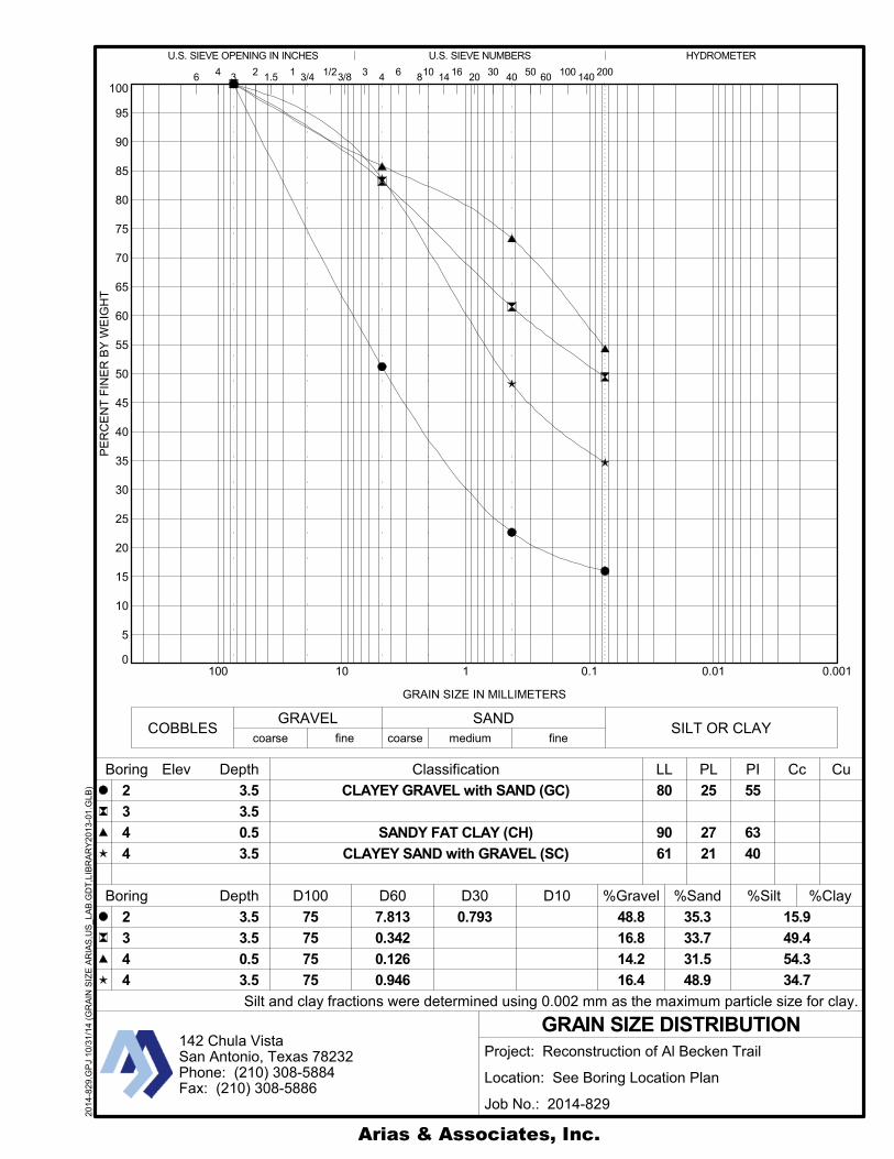
CLAYEY GRAVEL with SAND (GC)
SANDY FAT CLAY (CH)
CLAYEY SAND with GRAVEL (SC)
80
90
61
25
27
21
55
63
40
7.813
0.342
0.126
0.946
0.793 48.8
16.8
14.2
16.4
15.9
49.4
54.3
34.7
Silt and clay fractions were determined using 0.002 mm as the maximum particle size for clay.
3.5
3.5
0.5
3.5
75
75
75
75
35.3
33.7
31.5
48.9
Project: Reconstruction of Al Becken Trail
Location: See Boring Location Plan
Job No.: 2014-829
2014
-829
.GP
J 10
/31
/14
(GR
AIN
SIZ
E A
RIA
S,U
S_L
AB
.GD
T,L
IBR
AR
Y20
13-0
1.G
LB)
142 Chula VistaSan Antonio, Texas 78232Phone: (210) 308-5884Fax: (210) 308-5886

APPENDIX E: ASFE INFORMATION – GEOTECHNICAL REPORT


APPENDIX F: PROJECT QUALITY ASSURANCE

8811 Colesville Road Suite G106 Silver Spring, Maryland 20910 Voice: 301.565.2733 Fax: 301.589.2017 E-mail: [email protected] Internet: www.asfe.org
PROJECT QUALITY ASSURANCE
1
Construction materials engineering and testing (CoMET) consultants perform quality-assurance (QA) services to evaluate the degree to which constructors are achieving the specified conditions they’re contractually obligated to achieve. Done right, QA can save you time and money; prevent unanticipated-conditions claims, change orders, and disputes; and reduce short-term and long-term risks, especially by detecting molehills before they grow into mountains.
Many owners don’t do QA right because they follow bad advice; e.g., “CoMET consultants are all the same. They all have accredited facilities and certified personnel. Go with the low bidder.” But there’s no such thing as a standard QA scope of service, meaning that – to bid low – each interested firms must propose the cheapest QA service it can live with, jeopardizing service quality and aggravating risk for the entire project team. Besides, the advice is based on misinformation.
Fact: Most CoMET firms are not accredited, and the quality of those that are varies significantly. Accreditation – which is important – nonetheless means that a facility met an accrediting body’s minimum criteria. Some firms practice at a much higher level; others just barely scrape by. And what an accrediting body typically evaluates – management, staff, facilities, and equipment – can change substantially before the next review, two, three, or more years from now.
Fact: It’s dangerous to assume CoMET personnel are certified. Many have no credentials at all; some are certified by organizations of questionable merit, while others have a valid certification, but not for the services they’re assigned.
Some CoMET firms – the “low-cost providers” – want you to believe that price is the only difference between QA providers. It’s not, of course. Firms that sell low price typically lack the facilities, equipment, personnel, and insurance quality-oriented firms invest in to achieve the reliability concerned owners need to achieve quality in quality assurance.
A Message to Owners
Done right, QA can save you time and
money; prevent claims and disputes; and
reduce risks. Many owners don’t do QA
right because they follow bad advice.
Most CoMET firms are not accredited.
It’s dangerous to assume CoMET
personnel are certified.

PROJECT QUALITY ASSURANCE
To derive maximum value from your investment in QA, require the CoMET firm’s project manager to serve actively on the project team from beginning to end, a level of service that’s relatively inexpensive and can pay huge dividends. During the project’s planning and design stages, experienced CoMET professionals can help the design team develop uniform technical specifications and establish appropriate observation, testing, and instrumentation procedures and protocols. They can also analyze plans and specs much as constructors do, looking for the little errors, omissions, conflicts, and ambiguities that often become the basis for big extras and big claims. They can provide guidance about operations that need closer review than others, because of their criticality or potential for error or abuse. They can also relate their experience with the various constructors that have expressed interest in your project.
CoMET consultants’ construction-phase QA services focus on two distinct issues: those that relate to geotechnical engineering and those that relate to the other elements of construction.
The geotechnical issues are critically important because they are essential to the “observational method” geotechnical engineers use to significantly reduce the amount of sampling they’d otherwise require. They apply the observational method by developing a sampling plan for a project, and then assigning field representatives to ensure
samples are properly obtained, packaged, and transported. The engineers review the samples and, typically, have them tested in their own laboratories. They use the information they derive to characterize the site’s subsurface and develop preliminary recommendations for the structure’s foundations and for the specifications of various “geo” elements, like excavations, site grading, foundation-bearing grades, and roadway and parking-lot preparation and surfacing.
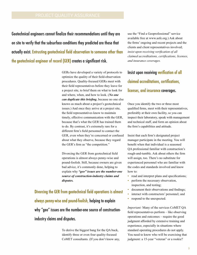
Geotechnical engineers cannot finalize
their recommendations until they or
their field representatives are on site to
observe what’s excavated to verify that
the subsurface conditions the engineers
predicted are those that actually exist.
When unanticipated conditions are observed, recommendations and/or specifications should be modified.
Responding to client requests, many geotechnical-engineering firms have expanded their field-services mix, so they’re able to perform overall construction QA, encompassing – in addition to geotechnical issues – reinforced concrete, structural steel, welds, fireproofing, and so on. Unfortunately, that’s caused some confusion. Believing that all CoMET consultants are alike, some owners take bids for the overall CoMET package, including the geotechnical field observation. Entrusting geotechnical field observation to someone other than the geotechnical engineer of record (GER) creates a significant risk.
Firms that sell low price typically lack the facilities, equipment, personnel,
and insurance quality-oriented firms invest in to achieve the reliability
concerned owners need to achieve quality in quality assurance.
To derive maximum value, require the project manager to
serve actively on the project team from beginning to end.
2
3
PROJECT QUALITY ASSURANCE
GERs have developed a variety of protocols to optimize the quality of their field-observation procedures. Quality-focused GERs meet with their field representatives before they leave for a project site, to brief them on what to look for and where, when, and how to look. (No one can duplicate this briefing, because no one else knows as much about a project’s geotechnical issues.) And once they arrive at a project site, the field representatives know to maintain timely, effective communication with the GER, because that’s what the GER has trained them to do. By contrast, it’s extremely rare for a different firm’s field personnel to contact the GER, even when they’re concerned or confused about what they observe, because they regard the GER’s firm as “the competition.”
Divorcing the GER from geotechnical field operations is almost always penny-wise and pound-foolish. Still, because owners are given bad advice, it’s commonly done, helping to explain why “geo” issues are the number-one source of construction-industry claims and disputes.
To derive the biggest bang for the QA buck, identify three or even four quality-focused CoMET consultants. (If you don’t know any,
use the “Find a Geoprofessional” service available free at www.asfe.org.) Ask about the firms’ ongoing and recent projects and the clients and client representatives involved; insist upon receiving verification of all claimed accreditations, certifications, licenses, and insurance coverages.
Insist upon receiving verification of all
claimed accreditations, certifications,
licenses, and insurance coverages.
Once you identify the two or three most qualified firms, meet with their representatives, preferably at their own facility, so you can inspect their laboratory, speak with management and technical staff, and form an opinion about the firm’s capabilities and attitude.
Insist that each firm’s designated project manager participate in the meeting. You will benefit when that individual is a seasoned QA professional familiar with construction’s rough-and-tumble. Ask about others the firm will assign, too. There’s no substitute for experienced personnel who are familiar with the codes and standards involved and know how to: • read and interpret plans and specifications; • perform the necessary observation,
inspection, and testing; • document their observations and findings; • interact with constructors’ personnel; and • respond to the unexpected.
Important: Many of the services CoMET QA field representatives perform – like observing operations and outcomes – require the good judgment afforded by extensive training and experience, especially in situations where standard operating procedures do not apply. You need to know who will be exercising that judgment: a 15-year “veteran” or a rookie?
Geotechnical engineers cannot finalize their recommendations until they are
on site to verify that the subsurface conditions they predicted are those that
actually exist. Entrusting geotechnical field observation to someone other than
the geotechnical engineer of record (GER) creates a significant risk.
Divorcing the GER from geotechnical field operations is almost
always penny-wise and pound-foolish, helping to explain
why “geo” issues are the number-one source of construction-
industry claims and disputes.

4
PROJECT QUALITY ASSURANCE
Also consider the tools CoMET personnel use. Some firms are passionate about proper calibration; others, less so. Passion is a good thing! Ask to see the firm’s calibration records. If the firm doesn’t have any, or if they are not current, be cautious. You cannot trust test results derived using equipment that may be out of calibration. Also ask a firm’s representatives about their reporting practices, including report distribution, how they handle notifications of nonconformance, and how they resolve complaints.
For financing purposes, some owners require the constructor to pay for CoMET services. Consider an alternative approach so you don’t convert the constructor into the CoMET consultant’s client. If it’s essential for you to fund QA via the constructor, have the CoMET fee included as an allowance in the bid documents. This arrangement ensures that you remain the CoMET consultant’s client, and it prevents the CoMET fee from becoming part of the constructor’s bid-price competition. (Note that the International Building Code (IBC) requires the owner to pay for Special Inspection (SI) services commonly performed by the CoMET consultant as a service separate from QA, to help ensure the SI services’ integrity. Because failure to comply could result in denial of an occupancy or use permit, having a contractual agreement that conforms to the IBC mandate is essential.)
If it’s essential for you to fund QA via the
constructor, have the CoMET fee included as
an allowance in the bid documents. Note,
too, that the International Building Code
(IBC) requires the owner to pay for Special
Inspection (SI) services.
CoMET consultants can usually quote their fees as unit fees, unit fees with estimated total (invoiced on a unit-fee basis), or lump-sum (invoiced on a percent-completion basis referenced to a schedule of values). No matter which method is used, estimated quantities need to be realistic. Some CoMET firms lower their total-fee estimates by using quantities they know are too low and then request change orders long before QA is complete.
Once you and the CoMET consultant settle on the scope of service and fee, enter into a written contract. Established CoMET firms have their own contracts; most owners sign them. Some owners prefer to use different contracts, but that can be a mistake when the contract was prepared for construction services. Professional services are different. Wholly avoidable problems occur when a contract includes provisions that don’t apply to the services involved and fail to include those that do.
Many of the services CoMET QA field representatives perform
require good judgment.
Scope flexibility is needed to deal promptly
with the unanticipated.
Some owners create wholly avoidable
problems by using a contract prepared for
construction services.

8811 Colesville Road Suite G106 Silver Spring, Maryland 20910 Voice: 301.565.2733 Fax: 301.589.2017 E-mail: [email protected] Internet: www.asfe.org
PROJECT QUALITY ASSURANCE
This final note: CoMET consultants perform QA for owners, not constructors. While constructors are commonly allowed to review QA reports as a courtesy, you need to make it clear that constructors do not have a legal right to rely on those reports; i.e., if constructors want to forgo their own observation and testing and rely on results derived from a scope created to meet only the needs of the owner, they
must do so at their own risk. In all too many cases where owners have not made that clear, some constructors have alleged that they did have a legal right to rely on QA reports and, as a result, the CoMET consultant – not they – are responsible for their failure to deliver what they contractually promised to provide. The outcome can be delays and disputes that entangle you and all other principal project participants. Avoid that. Rely on a CoMET firm that possesses the resources and attitude needed to manage this and other risks as an element of a quality-focused service. Involve the firm early. Keep it engaged. And listen to what the CoMET consultant says. A good CoMET consultant can provide great value.
For more information, speak with your ASFE-Member CoMET consultant or contact ASFE directly.
5

RFI #001 Response
Attachment 3

City of San Antonio Standard Specifications for Construction 23
ITEM
108 LIME TREATED SUBGRADE
108.1. DESCRIPTION: T r e a t t h e s u b g r a d e b y p u l v e r i z i n g , a d d i n g l i m e , m i x i n g , a n d c o m p a c t i n g t o t h er e q u i r e d d e n s i t y . T h i s i t e m a p p l i e s t o b o t h n a t u r a l g r o u n d a n d e m b a n k m e n t s u b g r a d e a n d s h a l lb e c o n s t r u c t e d a s s p e c if i e d h e r e i n a n d i n c o n f o r m a n c e w i t h t h e t y p i c a l s e c t i o n s , l i n e s a n d g r a d e sa s s h o w n o n t h e p l a n s o r a s e s t a b l i s h e d b y t h e E n g i n e e r .
108.2. MATERIALS: Lime for this item shall conform to the requirements of TxDOT Item No. 260,
“Lime Treatment – Road Mixed” of the Texas Department of Transportation Standard
Specifications (Latest Edition). Acceptable forms of lime shall be:
“Type A, Hydrated Lime,”
“Type B, Commercial Lime Slurry,” or
“Type C, Quicklime.”
The Contractor shall select, prior to construction, the grade to be used and shall notify the
Engineer in writing before changing from one grade to another. Lime shall be placed in slurry
form only, unless written permission is granted by the Engineer and a safety and containment
plan is submitted to the Engineer by the Contractor seven days prior to use. In circumstances
where it would be beneficial to utilize lime for “drying” subgrade materials to expedite
construction, the Contractor may request approval from the Engineer to use pelletized lime.
Provide materials in conformance with the following Items and requirements:
A. Lime. TxDOT DMS-6350 “Lime and Lime Slurry.”
B. Mix Design. The Engineer will determine the target lime content and optimum moisture
content in accordance with TxDOT Tex -121-E.
108.3. EQUIPMENT: The machinery, tools and equipment necessary for proper prosecution of the
work shall be on the project and approved by the Engineer prior to the beginning of construction
operations. All machinery, tools and equipment used shall be maintained in a satisfactory and
workmanlike manner.
When lime is furnished in trucks, the weight of lime shall be determined on certified scales and
delivered to the job site with exit ports sealed at the plant.
108.4. CONSTRUCTION:
A. General. The completed course shall be uniformly treated, free from loose or segregated
areas, of uniform density and moisture content, well bound for its full depth and shall have a
smooth surface.
B. Preparation of Subgrade or Existing Base. Prior to treating existing material, it shall be
shaped to conform to the typical sections, as shown on the plans.
Before pulverizing or scarifying an existing material, when directed by the Engineer, the
Contractor shall proof roll the roadbed in accordance with TxDOT Item 216, “Proof Rolling.”
June 2008 Item 108 Lime Treated Subgrade

City of San Antonio Standard Specifications for Construction 24
Soft spots shall be corrected as directed by the Engineer. When the Contractor elects to use a
cutting and pulverizing machine that will process the material to the plan depth, the
Contractor will not be required to excavate to the secondary grade or windrow the material.
This method will be permitted only if a machine is provided which will insure that the
material is cut uniformly to the proper depth and which has cutters that will plane the
secondary grade to a uniform surface over the entire width of the cut. The machine shall
provide a visible indication of the depth of cut at all times.
In lieu of using the cutting and pulverizing machine, the Contractor shall excavate and
windrow the material to expose the secondary grade to the typical sections, lines and grades
as shown on the plans or as established by the Engineer.
C. Pulverization. The existing pavement or base material shall be pulverized or scarified so that
100 % shall pass the 2-½ inch sieve.
D. Application. The percentage by weight or pounds per square yard of lime to be added will be
as shown on the plans and may be varied by the Engineer if conditions warrant.
Lime shall be spread only on that area where the mixing operations can be completed during
the same working day.
Unless otherwise approved by the Engineer, the lime operation shall not be started when the
air temperature is below 40ºF and falling, but may be started when the air temperature is
above 35ºF and rising. The temperature will be taken in the shade and away from artificial
heat. Lime shall not be placed when weather conditions in the opinion of the Engineer are
unsuitable.
The application and mixing of lime with the material shall be accomplished by the methods
herein described as “Slurry Placing.” “Dry Placing” is not allowed unless approved by the
Engineer as described in Section 108.2, “Materials.” Type A, Hydrated Lime shall be applied
by “Slurry Placing” unless otherwise shown on the plans or approved by the Engineer. Type
B Commercial Lime Slurry shall be applied by “Slurry Placing.” Type C Quicklime shall be
applied by “Slurry Placing” only. “Dry Placing” will not be allowed unless approved by the
Engineer. When Type C Quicklime is used for dry placement, it shall be Grade “DS.” When
Type C Quicklime is used for slurry placement, it shall be either Grade “DS” or Grade “S.”
Grade “S” shall be used in slurry placement only.
CAUTION: Use of quicklime can be dangerous. Users should be informed of the
recommended precautions in handling, storage and use of quicklime.
1. Slurry Placing. When Type A Hydrated Lime is specified and slurry placement is to be
used, the Type A Hydrated Lime shall be mixed with water to form a slurry with a solids
content approved by the Engineer.
Type B Commercial Lime Slurry shall be delivered to the project in slurry form at or
above the minimum dry solids content approved by the Engineer. The distribution of lime
at the rate(s) shown on the plans or approved by the Engineer shall be attained by
successive passes over a measured section of roadway until the proper lime content has
been secured.
When Type C Quicklime is applied as slurry, the amount of dry quicklime shall be 80
percent of the amount shown on the plans. The slurry shall contain at least the minimum
June 2008 Item 108 Lime Treated Subgrade

City of San Antonio Standard Specifications for Construction 25
dry solids content approved by the Engineer. The residue from the slurrying procedure
shall be spread uniformly over the length of the roadway currently being processed unless
otherwise approved by the Engineer. This residue is primarily inert material with little
stabilizing value, but may contain a small amount of quicklime particles that slake
slowly. A concentration of these particles could cause the compacted stabilized material
to swell during slaking.
Slurry shall be of such consistency that it can be applied uniformly without difficulty.
When the distributor truck is not equipped with an agitator, the Contractor shall have a
standby pump available on the project for agitating the lime and water as required by the
Engineer in case of undue delays in dispersing the slurry.
2. Dry Placing. Dry placing is not allowed unless approved by the Engineer as described in
Section 108.2, “Materials.” If allowed, the lime shall be distributed by an approved
spreader at the rate shown on the plans or as directed by the Engineer. The lime shall be
distributed at a uniform rate and in such a manner as to reduce the scattering of lime by
the wind. The material shall be sprinkled as approved by the Inspector.
E. Mixing. The mixing procedure shall be the same for “Slurry Placing” or “Dry Placing” as
herein described.
Begin Mixing within 6 hours of lime application. During the interval between application and
mixing, hydrated lime that has been exposed to the open air for a period of six (6) hours or
more or to excessive loss due to washing or blowing will not be accepted for payment.
1. Initial Mixing. The material and lime shall be thoroughly mixed. The material and lime
shall be brought to the proper moisture content and left to mellow for 1 to 4 days. When
pebble grade quicklime is used, allow the mixture to mellow for 2 to 4 days as approved
by the Engineer.
In addition to the above, when Type C Quicklime, Grade “DS,” is approved for use by
the Engineer under “Dry Placing,” the material and lime shall be mixed as thoroughly as
possible at the time of the lime application. Sufficient moisture shall be added during the
mixing to hydrate the quicklime.
During the mellowing period, the material shall be kept moist as directed by the
Inspector.
When shown on the plans or approved by the Engineer, the pulverization requirement
may be waived when the material contains a substantial quantity of aggregate.
2. Final Mixing. After the required mellowing time, the material shall be uniformly mixed
by approved methods. If the soil binder-lime mixture contains clods, they shall be
reduced in size by the use of approved pulverization methods.
Following mixing, a sample of the material at roadway moisture will be obtained for
pulverization testing. All non-slaking aggregates retained on the ¾ inch sieve will be
removed from the sample. The remainder of the material shall meet the following
pulverization requirement when tested by TXDOT Test Method Tex-101-E, Part III:
June 2008 Item 108 Lime Treated Subgrade

City of San Antonio Standard Specifications for Construction 26
Minimum passing 1 ¾” sieve 100
Minimum passing ¾” sieve 85
Minimum passing No. 4 sieve 60
F. Compaction. Prior to compaction, the material shall be aerated or sprinkled as necessary to
provide the optimum moisture. Compaction of the mixture shall begin immediately after final
mixing and in no case more than 24 hours after final mixing.
Compaction shall continue until the entire depth of the mixture is uniformly compacted.
Throughout this entire operation, the shape of the course shall be maintained by blading, and
the surface upon completion shall be smooth and in conformity with the typical sections, lines
and grades as shown on the plans or as established by the Engineer.
1. Ordinary Compaction. Roll with approved compaction equipment, as directed. Correct
irregularities, depressions, and weak spots immediately by scarifying the areas affected,
adding or removing treated material as required, reshaping, and recompacting.
2. Density Control. Each course shall be sprinkled as required and compacted to the extent
necessary to provide not less than 95 percent of the optimum density. Unless otherwise
shown on the plans, the Engineer will determine roadway density of completed sections
in accordance with TxDOT Test Method Tex-115-E. The Engineer may accept the
section if no more than 1 of the 5 most recent density tests is below the specified density
and the failing test is no more than 3 pcf below the specified density.
When the material fails to meet the density requirements, or should the material lose the
required stability, density or finish before the next course is placed, or the project is accepted,
it shall be reworked as specified below.
G. Reworking a Section. When a section is reworked within 72 hours after completion of
compaction, the Contractor shall rework the section to provide the required compaction.
When a section is reworked more than 72 hours after completion of compaction, the
Contractor shall add 25 percent of the specified rate of lime. Reworking shall include
loosening, road mixing as approved by the Engineer, compacting, and finishing. When a
section is reworked, a new optimum density will be determined from the reworked material in
accordance with TXDOT Test Method Tex-121-E, part II and shall compact in-place to a
minimum of 95% of this density.
H. Finishing. Immediately after completing compaction, clip, skin, or tight-blade the surface of
the lime treated material with a maintainer or subgrade trimmer to a depth of approximately
¼-inch. Remove loosened material and dispose of it at an approved location. Roll the clipped
surface immediately with a pneumatic-tire roller until a smooth surface is attained. Add small
increments of water as needed during rolling. Shape and maintain the course and surface in
conformity with the typical sections, lines and grades shown on the plans or as directed.
Finish grade of constructed subgrade in accordance with the following grade tolerances
1. Staged Construction. Grade to within 0.1-foot in the cross-section and 0.1-foot in 16-
feet measured longitudinally.
June 2008 Item 108 Lime Treated Subgrade
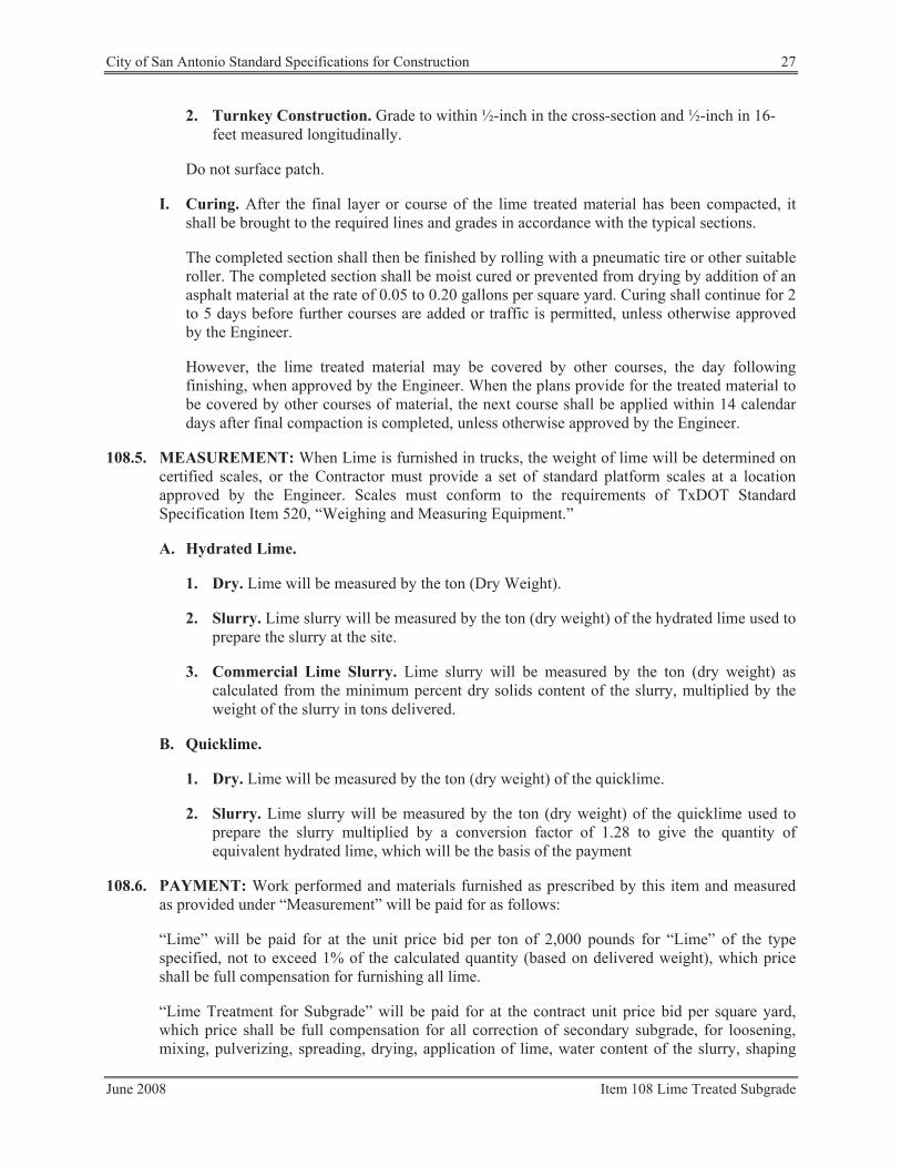
City of San Antonio Standard Specifications for Construction 27
2. Turnkey Construction. Grade to within ½-inch in the cross-section and ½-inch in 16-
feet measured longitudinally.
Do not surface patch.
I. Curing. After the final layer or course of the lime treated material has been compacted, it
shall be brought to the required lines and grades in accordance with the typical sections.
The completed section shall then be finished by rolling with a pneumatic tire or other suitable
roller. The completed section shall be moist cured or prevented from drying by addition of an
asphalt material at the rate of 0.05 to 0.20 gallons per square yard. Curing shall continue for 2
to 5 days before further courses are added or traffic is permitted, unless otherwise approved
by the Engineer.
However, the lime treated material may be covered by other courses, the day following
finishing, when approved by the Engineer. When the plans provide for the treated material to
be covered by other courses of material, the next course shall be applied within 14 calendar
days after final compaction is completed, unless otherwise approved by the Engineer.
108.5. MEASUREMENT: When Lime is furnished in trucks, the weight of lime will be determined on
certified scales, or the Contractor must provide a set of standard platform scales at a location
approved by the Engineer. Scales must conform to the requirements of TxDOT Standard
Specification Item 520, “Weighing and Measuring Equipment.”
A. Hydrated Lime.
1. Dry. Lime will be measured by the ton (Dry Weight).
2. Slurry. Lime slurry will be measured by the ton (dry weight) of the hydrated lime used to
prepare the slurry at the site.
3. Commercial Lime Slurry. Lime slurry will be measured by the ton (dry weight) as
calculated from the minimum percent dry solids content of the slurry, multiplied by the
weight of the slurry in tons delivered.
B. Quicklime.
1. Dry. Lime will be measured by the ton (dry weight) of the quicklime.
2. Slurry. Lime slurry will be measured by the ton (dry weight) of the quicklime used to
prepare the slurry multiplied by a conversion factor of 1.28 to give the quantity of
equivalent hydrated lime, which will be the basis of the payment
108.6. PAYMENT: Work performed and materials furnished as prescribed by this item and measured
as provided under “Measurement” will be paid for as follows:
“Lime” will be paid for at the unit price bid per ton of 2,000 pounds for “Lime” of the type
specified, not to exceed 1% of the calculated quantity (based on delivered weight), which price
shall be full compensation for furnishing all lime.
“Lime Treatment for Subgrade” will be paid for at the contract unit price bid per square yard,
which price shall be full compensation for all correction of secondary subgrade, for loosening,
mixing, pulverizing, spreading, drying, application of lime, water content of the slurry, shaping
June 2008 Item 108 Lime Treated Subgrade
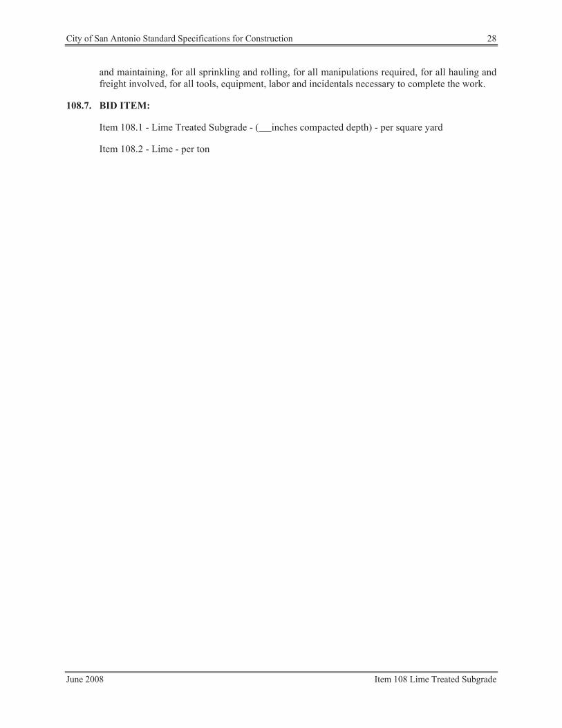
City of San Antonio Standard Specifications for Construction 28
and maintaining, for all sprinkling and rolling, for all manipulations required, for all hauling and
freight involved, for all tools, equipment, labor and incidentals necessary to complete the work.
108.7. BID ITEM:
Item 108.1 - Lime Treated Subgrade - ( inches compacted depth) - per square yard
Item 108.2 - Lime - per ton
June 2008 Item 108 Lime Treated Subgrade

RFI #001 Response
Attachment 4
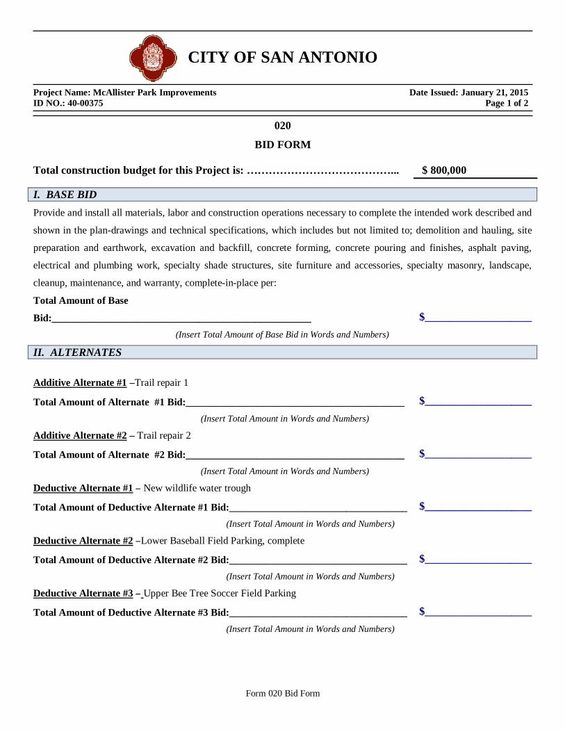
CITY OF SAN ANTONIO Project Name: McAllister Park Improvements Date Issued: January 21, 2015 ID NO.: 40-00375 Page 1 of 2
Form 020 Bid Form
020
BID FORM
Total construction budget for this Project is: …………………………………... $ 800,000
I. BASE BID Provide and install all materials, labor and construction operations necessary to complete the intended work described and
shown in the plan-drawings and technical specifications, which includes but not limited to; demolition and hauling, site
preparation and earthwork, excavation and backfill, concrete forming, concrete pouring and finishes, asphalt paving,
electrical and plumbing work, specialty shade structures, site furniture and accessories, specialty masonry, landscape,
cleanup, maintenance, and warranty, complete-in-place per:
Total Amount of Base
Bid:___________________________________________________ $_____________________
(Insert Total Amount of Base Bid in Words and Numbers)
II. ALTERNATES
Additive Alternate #1 –Trail repair 1
Total Amount of Alternate #1 Bid:___________________________________________ $_____________________
(Insert Total Amount in Words and Numbers)
Additive Alternate #2 – Trail repair 2
Total Amount of Alternate #2 Bid:___________________________________________ $_____________________
(Insert Total Amount in Words and Numbers)
Deductive Alternate #1 – New wildlife water trough
Total Amount of Deductive Alternate #1 Bid:___________________________________ $_____________________
(Insert Total Amount in Words and Numbers)
Deductive Alternate #2 –Lower Baseball Field Parking, complete
Total Amount of Deductive Alternate #2 Bid:___________________________________ $_____________________
(Insert Total Amount in Words and Numbers)
Deductive Alternate #3 – Upper Bee Tree Soccer Field Parking
Total Amount of Deductive Alternate #3 Bid:___________________________________ $_____________________
(Insert Total Amount in Words and Numbers)

McAllister Park Improvements – 40-00375 Page 2 of 2 ID NO. 40-00375-05-03
Form 020 Bid Form
Deductive Alternate #4 –Existing wildlife water trough automatic fill
Total Amount of Deductive Alternate #4 Bid:___________________________________ $_____________________
(Insert Total Amount in Words and Numbers)
Deductive Alternate #5 –Accessible picnic units (3 total)
Total Amount of Deductive Alternate #5 Bid:___________________________________ $_____________________
(Insert Total Amount in Words and Numbers)
Deductive Alternate #6 –Overflow parking area at dog park & practice field
Total Amount of Deductive Alternate #6 Bid:___________________________________ $_____________________
(Insert Total Amount in Words and Numbers)
III. UNIT PRICES Bidders shall complete and submit the unit pricing requested on the Section 025 Unit Pricing Form and it shall be attached immediately following this sheet. The unit prices bid shall be the 'complete-in-place unit costs' that is necessary and required to complete the unit bid item work described. The unit prices bid may be used by the City of San Antonio to change the intended scope and/or the final contract amount for this project by applying "additions-to" or "deletions-form" the scope of work, at the sole discretion of the City of San Antonio.
IV. ALLOWANCES
No Allowance Given for this Bid Request, N/A.
Official Name of Company (legal) Telephone No. Address Fax No. City, State and Zip Code E-mail Address Name of the Company Project Manager: ______________________________________________________ Name of the Company Site Superintendent: ____________________________________________________

Addendum No. 04
Attachment 2

RAM 30x44 TG/SS & CWC 14x16 SS McAllister Park San Antonio, TX Revision: 2/11/2015
by PorterCorp * Holland, MI * 49424 CSI Section 10 73 00 www.poligon.com * 616.399.1963 * fax 616.399.9123 Page 1 of 7
Poligon Steel Shelters by PorterCorp 4240 136th Ave., Holland, MI 49424
DIVISION 107300
SPECIALTIES MANUFACTURERS OF PROTECTIVE COVERS
PART 1 - GENERAL [reference CSI 2004 MasterFormat™ Division 10
(Specialties Manufacturers) category 7300 (Protective Covers)]
1.1 DESCRIPTION OF PRODUCT
A. RAM 30x44 TG/SS and CWC 14x15 SS B. ROOF SLOPE: RAM – 4:12, CWC - 2:12 C. Minimum Clearance Height (MCH): RAM 30x44 10’ and CWC 1416 7’-10”. Minimum
clearance height under the structure indicates the lowest height of a member from finish grade for clearance under the structure. This is generally the clearance under roof eave or frame, whichever is lower.
1.2 REFERENCES
A. REFERENCE STANDARDS: 1. AISC - American Institute of Steel Construction Manual of Steel Construction. 2. ASTM - American Society for Testing and Materials. 3. AWS - American Welding Society. 4. LEED - Leadership in Energy and Environmental Design. 5. OSHA – Occupational Safety and Health Administration Steel Erection Standard 29 CFR
1926 Subpart R-Steel Erection. 6. PCI - Powder Coating Institute. 7. SSPC - Steel Structures Painting Council.
1.3 SUBMITTALS
A. GENERAL SUBMITTAL: Submit 4 sets of submittal drawings and 2 sets of calc books, both signed and sealed by a Professional Engineer licensed in the State of Texas.
B. PRODUCT DESIGN REQUIREMENTS:
The building shall meet the following design requirements as shown on the drawings: 1. Building Code: IBC 2009 2. Ground Snow Load (Pg): 20 psf 3. Basic Wind Speed (V): 90 mph
4. Seismic Design: D

RAM 30x44 TG/SS & CWC 14x16 SS McAllister Park San Antonio, TX Revision: 2/11/2015
by PorterCorp * Holland, MI * 49424 CSI Section 10 73 00 www.poligon.com * 616.399.1963 * fax 616.399.9123 Page 2 of 7
C. SUBMITTAL REQUIREMENTS:
Calculations and Submittal drawings shall include, at a minimum: 1. Calculations:
a. References to building codes and design manuals used for calculations. b. Identification of lateral force resisting system. c. Formulas used for determining snow, wind, and seismic loads to specific project
location. d. Three dimensional modeling input, model geometry, and analysis results. e. Member design results and controlling load combinations. f. Connection design for structural bolts, welds, plate thicknesses, and anchorage to
the foundation. g. Foundation designs must include the required combinations of gravity and lateral
loads. 2. Submittal Drawings:
a. Anchor bolt layout. b. Foundation design. c. Three dimensional views of frame. d. Member sizes and locations. e. Structural connection details, including bolt sizes and plate thicknesses. f. Roof trim and connection details.
D. FOUNDATION DESIGN:
1. The shelter shall be set on foundations designed by manufacturer. 2. Foundation materials shall be provided by contractor. 3. Owner shall provide manufacturer with complete information about the site including soil
bearing capacity and lateral load capacity. 4. If soil data are not provided, foundations will be designed to the minimum values
identified in the governing building code.
E. ANCHOR BOLTS: Anchor bolts shall be provided by manufacturer.
1.4 QUALITY ASSURANCE
A. MANUFACTURER QUALIFICATIONS:
1. Minimum of 10 years in the shelter construction industry. 2. Full time on-staff Licensed Engineer. 3. Full time on-staff AWS Certified Welding Inspector. 4. Full time on-staff Quality Assurance Manager. 5. Full time on-staff LEED AP. 6. All welders AWS Certified. 7. Manufacturer owned and controlled finishing system to include shot blast, pretreatment,
primer, and top coat. 8. Published Quality Management System. 9. Annual audit of Quality System and Plant Processes by Third Party Agency. 10. Annual audit of powder coat finish system by Third Party Agency (PCI).

RAM 30x44 TG/SS & CWC 14x16 SS McAllister Park San Antonio, TX Revision: 2/11/2015
by PorterCorp * Holland, MI * 49424 CSI Section 10 73 00 www.poligon.com * 616.399.1963 * fax 616.399.9123 Page 3 of 7
B. MANUFACTURER’S CERTIFICATONS:
1. PCI 4000 S Certified, Certification thru PCI for original equipment manufacturers (OEMs) to evaluate process on entire finish system to add powder coat over steel. 2. City of Los Angeles, CA Approved Fabricator Type I Steel. 3. Clark County, NV Approved Fabricator steel. 4. City of Houston, TX Approved Fabricator Structural Steel and Structural Insulated Panels. 5. Miami Dade County Certificate of Competency for Structural Steel and Miscellaneous
Metal Products and Assemblies. 6. State of Utah Approved Fabricator for Medium and High Strength Steel. 7. City of Riverside, CA Approved Fabricator Type I Steel. 8. City of Phoenix, AZ Approved Steel Fabricator.
1.5 FIELD OR SITE CONDITIONS
A. Foundations shall be at the same elevation unless specifically noted otherwise on the drawings.
1.6 MANUFACTURER WARRANTY
A. Shelter must have a 10-year limited warranty on steel frame members. B. Shelter must have a 10-year limited warranty on paint system. C. Pass through warranty of Metal Roof manufacturer shall be provided upon request.
PART 2 - PRODUCTS 2.1 SHELTER SYSTEM AND MATERIALS
A. MANUFACTURERS: 1. Acceptable Manufacturer: Poligon, a Product of PorterCorp, 4240 N 136th Ave., Holland,
MI 49424; 616.399.1963; E-mail: [email protected]; www.poligon.com. Receive pricing from BJ’s Park & Recreation Products, 4003 Briar Lane, Magnolia, TX 77354, 281.356.2110, E-mail: [email protected], www.bjspark.com
2. The product shall be designed, produced, and finished at a facility operated and directly supervised by the supplier who has a minimum of ten years in the business making pre-manufactured shelters.
B. SUBSTITUTION LIMITATIONS:
1. Substitutions must be approved a minimum of ten (10) days before bid. All approved manufacturers shall be notified in writing before the bid date and shall not be allowed to bid without written notification.
2. Alternate suppliers must meet the qualifications and provide proof of certifications listed under Section 1.4 QUALITY ASSURANCE.

RAM 30x44 TG/SS & CWC 14x16 SS McAllister Park San Antonio, TX Revision: 2/11/2015
by PorterCorp * Holland, MI * 49424 CSI Section 10 73 00 www.poligon.com * 616.399.1963 * fax 616.399.9123 Page 4 of 7
3. Alternate suppliers must provide an equivalent paint system to Poligon’s Poli-5000 listed under Section 2.1 C. 8. FINISHES.
4. Staff members’ cumulative experience in fabrication will not be an acceptable alternative for manufacturer’s experience in the shelter construction industry.
C. PRODUCT REQUIREMENTS AND MATERIALS:
1. GENERAL: The pre-engineered package shall be pre-cut unless otherwise noted and pre-fabricated which will include all parts necessary to field construct the shelter. The shelter shall be shipped knocked to minimize shipping expenses. Field labor will be kept to a minimum by pre-manufactured parts. Onsite welding is not necessary.
2. REINFORCED CONCRETE: a. Concrete shall have minimum 28-day compressive strength of 3,000 psi and slump
of 4” (+/- 1”), unless otherwise noted on the drawings. b. Reinforcing shall be ASTM A615, grade 60.
3. STEEL COLUMNS: a. Hollow structural steel tube minimum ASTM A500 grade B with a minimum wall
thickness of 3/16”. b. Unless columns are direct buried, columns shall be anchored directly to concrete
foundation with a minimum of four anchor rods to meet OSHA requirement 1926.755(a)(1).
c. CUSTOM STEEL COLUMNS: 4. STRUCTURAL FRAMING:
Hollow Structural Steel tube minimum ASTM500 grade B. “I” beams, tapered columns, or open channels shall not be accepted for primary beams. Frame will have a E-COAT BASE COAT finish. Color chosen from manufacturer's standard color chart: [____________].
5. COMPRESSION MEMBERS: Compression rings of structural channel or welded plate minimum ASTM A36 or compression tubes or structural steel tube minimum ASTM A500 grade B shall only be used.
6. CONNECTION REQUIREMENTS: a. Anchor bolts shall be ASTM F1554 (Grade 36) unless otherwise noted. b. Structural fasteners shall be zinc plated ASTM A325 high strength bolts and A563
high strength nuts. c. All structural fasteners shall be hidden within framing members wherever possible. d. No field welding shall be required to construct the shelter. e. All welds shall be free of burrs and inconsistencies. f. All exposed fasteners shall be painted by manufacturer prior to shipment to match
frame or roof colors as applicable. g. Manufacturer shall provide extra structural and roofing fasteners.
7. ROOFING MATERIALS: RAM 30x44 TG/SS
a. PRIMARY ROOF DECK: FACTORY PRE-STAINED TONGUE AND GROOVE (TG): 1) T&G shall beof 2x6 tongue and groove, Hem Fir, Select Structural KD 15.
Factory stained [ ] 2) Manufacturer shall supply 30 pound felt and drip edge if both primary and
secondary roofs are being supplied by the manufacturer.

RAM 30x44 TG/SS & CWC 14x16 SS McAllister Park San Antonio, TX Revision: 2/11/2015
by PorterCorp * Holland, MI * 49424 CSI Section 10 73 00 www.poligon.com * 616.399.1963 * fax 616.399.9123 Page 5 of 7
3) Contractor shall cut T&G down to required lengths. CWC 14x16 SS a. PRIMARY ROOF DECK OF STANDING SEAM METAL ROOFING:
1) Standing seam metal roofing to be 24-gauge galvalume 16” wide with ribs 1-3/4” high.
2) Roof surface shall be painted with Kynar 500 to the manufacturer’s standard color: [__________]. Ceiling surface shall be a “wash coat” primer.
3) Angles shall be cut in the field. 4) Metal roofing trim shall match the color of the roof and shall be factory made of
26 gauge Kynar 500 painted steel. 5) Trim shall include panel ridge caps, hip caps, eave trim, splice channels, rake
trim, roof peak cap, and corner trim as applicable for model selected. Trim may need to be cut to length and notched. Reference drawings for additional information.
6) Ridge, hip, and valley caps shall be pre-formed with a single central bend to match the roof pitch and shall be hemmed on the sides.
7) Roof peak cap shall be pre-manufactured. 8) Manufacturer must supply painted screws and butyl tape.
RAM 30x44 TG/SS b. SECONDARY ROOF SYSTEM OF STANDING SEAM METAL ROOFING:
1) Standing seam metal roofing to be 24-gauge galvalume 16” wide with ribs 1-3/4” high.
2) Roof surface shall be painted with Kynar 500 to the manufacturer’s standard color: [__________]. Ceiling surface shall be a “wash coat” primer.
3) Angles shall be cut in the field. 4) Metal roofing trim shall match the color of the roof and shall be factory made of
26 gauge Kynar 500 painted steel. 5) Trim shall include panel ridge caps, hip caps, eave trim, splice channels, rake
trim, roof peak cap, and corner trim as applicable for model selected. Trim may need to be cut to length and notched. Reference drawings for additional information.
6) Ridge, hip, and valley caps shall be pre-formed with a single central bend to match the roof pitch and shall be hemmed on the sides.
7) Roof peak cap shall be pre-manufactured. 8) Manufacturer must supply painted screws and butyl tape.
8. FINISHES: a. E-COAT BASE COAT FINISH:
1) Entire building under Super Durable Polyester TGIC powder coat shall have an E-Coat Base Coat.
2) Steel shall be shot blasted to SSPC-SP10 near-white blast cleaning prior to adding E-Coat. SSPC-SP2 hand tool cleaning will not be an acceptable alternative.
3) Top powder coat of Super Durable TGIC powder coat shall be applied. 9. ACCESSORIES
b. ELECTRICAL ACCESS: 1) Electrical access to be provided per manufacturer’s electrical access sheet.
RAM 30x44 TG/SS & CWC 14x16 SS McAllister Park San Antonio, TX Revision: 2/11/2015
by PorterCorp * Holland, MI * 49424 CSI Section 10 73 00 www.poligon.com * 616.399.1963 * fax 616.399.9123 Page 6 of 7
2) Electrical cutouts shall be marked as height above finish floor and size of cutout required.
PART 3 - EXECUTION
3.1 INSTALLERS STORAGE AND HANDLING
A. Protect building products after arrival at destination from weather, sunlight, and damage. B. Installer shall store product elevated from soils to allow air circulation and to not introduce
mold, fungi decay or insects to the product.
C. Product must be handled with protective straps or padded forks if lifting with mechanical equipment. Use of chain or cable to lift product into place will not be accepted.
D. To curtail warping of lumber, all units shall remain packaged while being stored. E. The secondary roof shall be installed immediately after the primary roof to prevent moisture
damage to wood.
3.2 ERECTION
A. FOUNDATIONS: The shelter shall be placed on foundations designed by PorterCorp, with materials by others. Design approved by the Engineer of Record identified in Section 1.3 D. FOUNDATION DESIGN.
B. INSTALLATION: Install all components according to manufacturer’s installation instructions and these specifications.
C. GENERAL CONTRACTOR:
Interface with other work is to be coordinated by the customer or the customer’s agent. Certain designs have electrical or other plumbing requirements that are not supplied by Poligon.
D. TOLERANCES:
Tolerances on steel structural members are set according to AISC construction practices, abided in the factory, and cannot be increased. No field slotting or opening of holes will be allowed. It is therefore essential that contractors conform to the tolerances specified on the installation drawings for anchor bolt or column layout details.
E. OSHA COMPLIANCE:
OSHA Compliance to Steel Erection Standard 29CRF 1926 Subpart R-Steel Erection. 3.3 REPAIR

RAM 30x44 TG/SS & CWC 14x16 SS McAllister Park San Antonio, TX Revision: 2/11/2015
by PorterCorp * Holland, MI * 49424 CSI Section 10 73 00 www.poligon.com * 616.399.1963 * fax 616.399.9123 Page 7 of 7
A. Do not attempt any field changes without first contacting Poligon.
3.4 FIELD OR SITE QUALITY CONTROL
A. Field or Site Tests and Inspections are not required by Poligon but may be required by the customer or by the local building inspector.
END OF SECTION

GENERAL NOTES:N SS NOT D OT RWIS , T IS STR CT R WAS D SI N D TO ON S PPORT W AT IS S OWN ON T S DRAWIN S. PO I ON M ST B CONTACT D IF AN T IN S IS TO B ATTAC D TO T IS STR CT R (WA S, CO MN WRAPS, RAI IN S, TC.) SO T D SI N OF T IS STR CT R CAN B R VI W D AND POSSIB R VIS D.
N SS NOT D OT RWIS , T IS STR CT R WAS D SI N D ASS MIN A 20 S PARATION B TW N AN ADJAC NT STR CT R WIT AN AV I T A TO OR R AT R T AN T AV I T OF T IS STR CT R . IF T AT S PARATION DO S NOT IST,
PO I ON M ST B CONTACT D SO T D SI N OF T IS STR CT R CAN B R VI W D AND POSSIB R VIS D.
STR CT RA ST S A B D TAI D, FABRICAT D, AND R CT D IN ACCORDANC WIT T AT ST DITION OF T AM RICAN INSTIT T OF ST CONSTR CTION (AISC) SP CIFICATION MAN A .
A W DIN IS P RFORM D B AM RICAN W DIN SOCI T C RTIFI D W D RS AND CONFORMS TO T AT ST DITION OF AWS D1.1 OR D1.3 AS R IR D.
PARTS S OWN MA B P RAD D D TO STANDARDI D FABRICATION. R F R TO T S IPPIN BI OF MAT RIA S FOR POSSIB S BSTIT TIONS.
FOR PROP R FI D INSTA ATION OF T B I DIN IT IS R COMM ND D T AT T PRIMAR FRAM INSTA R AND T ROOF INSTA R AV A MINIM M FIV (5) ARS DOC M NT D P RI NC INSTA IN T IS T P OF PROD CT.
FOR PROP R FI D INSTA ATION OF T B I DIN IT IS R COMM ND D T AT CTRIC WIRIN , IF R IR D, B R N T RO T STR CT RA M MB RS B FOR T B I DIN IS R CT D.
MATERIALS:
D SCRIPTION T B STSC D PIPRMT PIPI T A CO D FORM DSTR CT RA ST P ATROOF PAN S (ST )
ASTM D SI NATIONA500 ( RAD B)A53 ( RAD B)A519A1003 ( RAD 50)A36A653
FABRICATOR APPROVALS:CIT OF P O NI , A APPROV D FABRICATOR C08-2010CIT OF OS AN S, CA APPROV D FABRICATOR 1596CIT OF RIV RSID , CA APPROV D FABRICATOR SP06-0033CIT OF O STON, T APPROV D FABRICATOR 470C AR CO NT , NV APPROV D FABRICATOR 264STAT OF TA APPROV D FABRICATOR 02008-14
CERTIFICATES:MIAMI-DAD CO NT C RTIFICAT OF COMP T NC NO. 13-0813.16PCI (POWD R COATIN INSTIT T ) 4000 C RTIFI D
CUSTOMER APPROVAL
MAN FACT RIN CANNOT START NTI PORT RCORP R C IV S A SI N D AND APPROV D COP .
APPROV D AS S BMITT D
APPROV D AS NOT D
R VIS AND R S BMIT AS NOT D
SI NAT R :
PRINT NAM :
DAT :
U
PATENTED OR PATENTS PENDING
(616)399-1963
byPORTERCORP 4240 N. 136th AVE HOLLAND, MI 49424
www.poligon.com
PORTERCORP
COPYRIGHT 2013
USE FOR PRELIMINARY PLANNING AND ESTIMATING
ONLY
STOP!! NOT FOR CONSTRUCTION
U
A Division of PORT RCORP 4240 N. 136th AV O AND, MI 49424 (616) 399-1963
Designs and calculations of Poligon buildings are protected under copyright laws and patents
and may not be used in the construction or design of a building that is not supplied by Poligon.
Copyright laws protect the style and visual appearance of the structure while patents may protect other parts of the design.
PATENTED AND/OR PATENTS PENDING COPYRIGHT 2013 PORTERCORP HOLLAND, MI 49424
SHEET NUMBER DRAWING DESCRIPTIONCS COVER SHEET1 ARCHITECTURAL ELEVATIONS2 STRUCTURAL FRAMING PLAN3 COLUMN LAYOUT4 BASE PLATE STYLES5 ELECTRICAL ACCESS AND CUTOUTS
PROJ CT:
OCATION:
DRAWIN IST:
B I DIN T P :
ROOF T P :
MCA IST R PAR
STANDIN S AM OV R T
IP ROOF 30 44
1:75
SAN ANTONIO, T
52872JOB N MB R:
CAD MODEL:
betdue
DRAWN BY:
SCALE:
REV LEVEL:
PRINT DATE:
~E1-RAM-30X44-TGSS-H10-52872
2/5/2015
AJOB NO:
52872
SAN ANTONIO, TX
MCALLISTER PARK
DRAWING:
COVER SHEET
PROJECT LOCATION:
PROJECT:
CSSHEET
F AT R S: 10 MC
2014A

USE FOR PRELIMINARY PLANNING AND ESTIMATING
ONLY
STOP!! NOT FOR CONSTRUCTION
U
PATENTED OR PATENTS PENDING
(616)399-1963
byPORTERCORP 4240 N. 136th AVE HOLLAND, MI 49424
www.poligon.com
PORTERCORP
COPYRIGHT 2013
16'- 7/16"- REF.
30'-1"- REF.
44'-1" - REF.
10'-0" UNDERPERIMETER BEAM
124
FINISH GRADE.MOUNTING VARIES BASED ON ENGINEERING REQUIREMENTS.
BASE IS ILLUSTRATIVE, N.I.C.
TOP VIEW
AUXILIARY VIEW
ELEVATION A ELEVATION B
ARCHITECTURAL ELEVATIONS
1
GENERAL ROOF NOTES:
METAL ROOFING:1.24 GAUGEÅGALVALUME COATEDÅKYNAR 500 PAINTEDÅ
TRIM COLOR MATCHES ROOF2.SEE POLIGON.COM FOR 3.COLOR OPTIONS
1:85
CAD MODEL:
betdue
DRAWN BY:
SCALE:
REV LEVEL:
PRINT DATE:
~E1-RAM-30X44-TGSS-H10-52872
2/5/2015
AJOB NO:
52872
SAN ANTONIO, TX
MCALLISTER PARK
DRAWING:
PROJECT LOCATION:
PROJECT:
SHEET
2014A

USE FOR PRELIMINARY PLANNING AND ESTIMATING
ONLY
STOP!! NOT FOR CONSTRUCTION
U
PATENTED OR PATENTS PENDING
(616)399-1963
byPORTERCORP 4240 N. 136th AVE HOLLAND, MI 49424
www.poligon.com
PORTERCORP
COPYRIGHT 2013
15'-8 1/2"- REF.
10'-0" UNDERPERIMETER BEAM
FINISH GRADE.MOUNTING VARIES BASED ON ENGINEERING REQUIREMENTS.
ELEVATION A ELEVATION B
AUXILIARY VIEW
TOP VIEW
STRUCTURAL FRAMING PLAN
2SHEET
GENERAL FRAME NOTES:ALL STEEL COMPONENTS (STRUCTURAL 1.MEMBERS, ORNAMENTATION, RAILING, ETC.) ARE POWDER COATED IN THE FOLLOWING MANNER (UNLESS REQUESTED OTHERWISE):
SHOT BLASTED TO NEAR WHITE ÅCONDITION (SSPC SP-10)WASHED AND SEALED IN A PHOSPHATE ÅSPRAYPRIME-COATED WITH POLI-5000 HIGH ÅPERFORMANCE POWDER APPLIED EPOXYTOP-COATED WITH SUPER-DURABLE TGIC ÅPOLYESTER POWDER AND OVEN CURED
SEE POLIGON.COM FOR COLOR OPTIONS2.
1:85
CAD MODEL:
betdue
DRAWN BY:
SCALE:
REV LEVEL:
PRINT DATE:
~E1-RAM-30X44-TGSS-H10-52872
2/5/2015
AJOB NO:
52872
SAN ANTONIO, TX
MCALLISTER PARK
DRAWING:
PROJECT LOCATION:
PROJECT:
SHEET
2014A
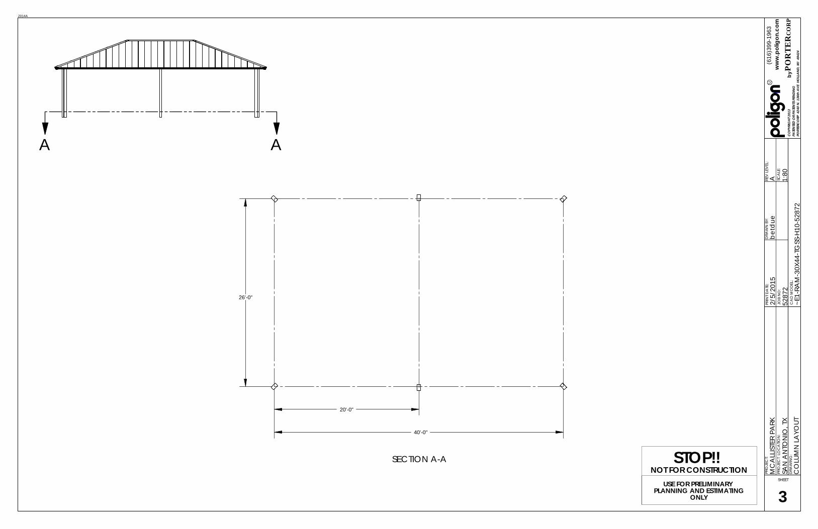
USE FOR PRELIMINARY PLANNING AND ESTIMATING
ONLY
STOP!! NOT FOR CONSTRUCTION
U
PATENTED OR PATENTS PENDING
(616)399-1963
byPORTERCORP 4240 N. 136th AVE HOLLAND, MI 49424
www.poligon.com
PORTERCORP
COPYRIGHT 2013
AA
20'-0"
40'-0"
26'-0"
SECTION A-A
COLUMN LAYOUT
3
1:80
CAD MODEL:
betdue
DRAWN BY:
SCALE:
REV LEVEL:
PRINT DATE:
~E1-RAM-30X44-TGSS-H10-52872
2/5/2015
AJOB NO:
52872
SAN ANTONIO, TX
MCALLISTER PARK
DRAWING:
PROJECT LOCATION:
PROJECT:
SHEET
2014A

USE FOR PRELIMINARY PLANNING AND ESTIMATING
ONLY
STOP!! NOT FOR CONSTRUCTION
U
PATENTED OR PATENTS PENDING
(616)399-1963
byPORTERCORP 4240 N. 136th AVE HOLLAND, MI 49424
www.poligon.com
PORTERCORP
COPYRIGHT 2013
POLIGON ENGINEERING WILL DETERMINE THE REQUIRED BASE PLATE STYLE WHEN DESIGNING THIS STRUCTURE.
NOTES:THE REQUIRED BASE PLATE STYLE IS A FUNCTION OF THE PROJECT SPECIFIC ENGINEERING REQUIREMENTS.1.POLIGON ENGINEERING WILL DETERMINE THE REQUIRED BASE PLATE STYLE BECAUSE IT CAN2.DRAMATICALLY AFFECT THE STRUCTURE'S DESIGN AND PERFORMANCE. WE UNDERSTAND THE BASE PLATE STYLE CAN IMPACT THE CONSTRUCTION SEQUENCE (I.E. THE TIMING OF3.THE SLAB INSTALLATION), SO PLEASE USE THE FOLLOWING INFORMATION AS A GENERAL GUIDE:
PINNED BASE PLATES ARE PROVIDED ON THE MAJORITY OF POLIGON STRUCTURESÅFIXED BASE PLATES ARE TYPICALLY ONLY REQUIRED IN HIGH SEISMIC REGIONS, ON SOMEÅLARGE STRUCTURES (> 2000 SQ FT), AND ON CANTILEVERED STRUCTURES.
IF YOUR PROJECT HAS UNIQUE BASE PLATE, SLAB, OR FOUNDATION REQUIREMENTS, PLEASE4.COMMUNICATE THAT INFORMATION WITH POLIGON WHEN PLACING AN ENGINEERING ORDER.
TOP OF CONCRETE FOUNDATION(DESIGN BY POLIGON)(MATERIALS NOT BY POLIGON)
ANCHOR BOLTS
ELECTRICAL ACCESS (OPTIONAL)
NON-SHRINK GROUT
FIXED BASE(WITHOUT CONCEALING SLAB)
TOP OF CONCRETE SLAB(DESIGN & MATERIALSNOT BY POLIGON)
(OPTIONAL)
ELECTRICAL ACCESS (OPTIONAL)
ANCHOR BOLTS
TOP OF CONCRETE FOUNDATION(DESIGN BY POLIGON)(MATERIALS NOT BY POLIGON)
TOP OF CONCRETE SLAB(DESIGN & MATERIALSNOT BY POLIGON)
(OPTIONAL)
NON-SHRINK GROUT
FIXED BASE(WITH CONCEALING SLAB)
TOP OF CONCRETE FOUNDATION(DESIGN BY POLIGON)(MATERIALS NOT BY POLIGON)
ELECTRICAL ACCESS (OPTIONAL)
ANCHOR BOLTS
ANCHOR BOLTACCESS HOLE
TOP OF CONCRETE SLAB(DESIGN & MATERIALSNOT BY POLIGON)
(OPTIONAL)
PINNED BASE
TOP OF CONCRETE SLAB(DESIGN & MATERIALSNOT BY POLIGON)
(OPTIONAL)TOP OF CONCRETE FOUNDATION(DESIGN BY POLIGON)(MATERIALS NOT BY POLIGON)
PRECAST BASE(NOT BY POLIGON)
DIRECT BURY
BASE PLATE STYLES
4
1:6
CAD MODEL:
betdue
DRAWN BY:
SCALE:
REV LEVEL:
PRINT DATE:
~E1-RAM-30X44-TGSS-H10-52872
2/5/2015
AJOB NO:
52872
SAN ANTONIO, TX
MCALLISTER PARK
DRAWING:
PROJECT LOCATION:
PROJECT:
SHEET
2014A

U
PATENTED OR PATENTS PENDING
(616)399-1963
byPORTERCORP 4240 N. 136th AVE HOLLAND, MI 49424
www.poligon.com
PORTERCORP
COPYRIGHT 2013
4-1/8" 4-1/8"
4-1/8"
1-1/16"
2 1/4"
3/4"
TYPICALWIRE RUN
BASE PLATE
COLUMN
LOWER TRUSS TAIL
LOWER TRUSS
TENSION MEMBER
LOWER PURLIN
UPPER PURLIN
JUNCTURE COLUMNCLERESTORY MEMBER
UPPER TRUSS TAIL
UPPER TRUSSCOMPRESSION
RING/TUBEOR RIDGE BEAM
COLUMN
TRUSS TAIL
TRUSS
COMPRESSIONRING/TUBE
OR RIDGE BEAM
PURLIN
TENSION MEMBER
TYPICALWIRE RUN
BASE PLATE
ELECTRICAL HOLES
DOUBLE GANG CUTOUT
SINGLE GANG CUTOUT
TYPICAL ELECTRICAL CUTOUTS
TYPICAL WIRE RUNS
ELECTRICAL ACCESS AND CUTOUTS
WHAT IS ELECTRICAL ACCESS?A 1-1/8" HOLE IS PROVIDED THROUGH COLUMN BASEPLATE.Å3/4" HOLES ARE PROVIDED THROUGH CONNECTION PLATES TO ALLOW WIRE ÅACCESS UP INTO COMPRESSION TUBE/RING OR RIDGE BEAM.ELECTRICAL ACCESS INTO ADDITIONAL MEMBERS IS AVAILABLE UPON REQUEST.Å
WHAT ARE ELECTRICAL CUTOUTS?ROUND HOLE OR RECTANGULAR CUTOUTS IN MEMBERS, REQUIRED FOR ÅINSTALLATION OF ELECTRICAL FIXTURES OR WIRE ACCESS.ALL CUTOUT REQUESTS MUST BE REVIEWED BY OUR ENGINEERING DEPARTMENT Å(THEIR PLACEMENT MAY AFFECT STRUCTURAL INTEGRITY).POLIGON IS NOT RESPONSIBLE FOR UNAUTHORIZED CUTOUTS MADE IN THE FIELD.ÅUNAUTHORIZED ELECTRICAL CUTOUTS MADE IN THE FIELD WILL VOID THE ÅSHELTER'S WARRANTY.TO ENSURE FLUSH MOUNTING OF AN ELECTRICAL FIXTURE, ROUND COLUMNS ÅWILL BE EQUIPPED WITH A WELDED IN ENCLOSURE THAT ACCOMMODATES A STANDARD UL LISTED BOX.
HOW TO COMMUNICATE CUTOUT REQUIREMENTSWHEN ORDERING THE STRUCTURE, MARK UP THE SUBMITTAL DRAWINGS TO ÅACCURATELY COMMUNICATE CUTOUTS WITH EXACT DIMENSION(S) AND LOCATION(S). IF THE SUBMITTAL SET IS NOT AVAILABLE, MARK UP THE SKETCHES ON THIS SHEET ÅSHOWING CUTOUTS WITH EXACT DIMENSION(S) AND LOCATION(S).CUTOUT SIZE MUST BE COMMUNICATED AT TIME OF ORDER.ÅINDICATE ON WHICH SIDE OF MEMBER THE CUTOUT IS TO BE LOCATED.ÅIF NOT SPECIFIED TO THE BOTTOM, CENTER, OR TOP OF CUTOUT, DIMENSION WILL ÅBE TAKEN TO THE BOTTOM OF THE CUTOUT.
WHERE CAN CUTOUTS BE LOCATED?OUTLET CUTOUTS ARE TYPICALLY LOCATED 18" ABOVE GRADE ON THE INSIDE ÅFACE OF THE COLUMN.LIGHT SWITCH CUTOUTS ARE TYPICALLY LOCATED 48" ABOVE GRADE ON THE ÅINSIDE FACE OF THE COLUMN.ALL CUTOUTS ARE TYPICALLY AT LEAST 12" FROM ANY STRUCTURAL JOINTS.ÅALL CUTOUTS ARE TYPICALLY CENTERED ON THE MEMBER WALL (NOT CLOSE TO ÅTHE CORNERS).CONTACT LOCAL POLIGON REPRESENTATIVE WITH ANY ADDITIONAL QUESTIONS.ÅCUTOUTS CAN BE LOCATED THROUGH COVER PLATES.Å
ELECTRICAL ACCESS AND CUTOUTS
5
1:32
CAD MODEL:
betdue
DRAWN BY:
SCALE:
REV LEVEL:
PRINT DATE:
~E1-RAM-30X44-TGSS-H10-52872
2/5/2015
AJOB NO:
52872
SAN ANTONIO, TX
MCALLISTER PARK
DRAWING:
PROJECT LOCATION:
PROJECT:
SHEET
2014A
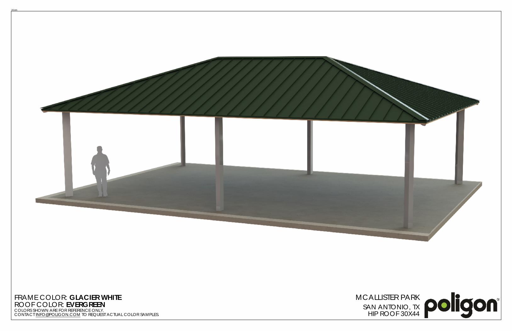
FRAME COLOR: GLACIER WHITEROOF COLOR: EVERGREENCOLORS SHOWN ARE FOR REFERENCE ONLY. CONTACT [email protected] TO REQUEST ACTUAL COLOR SAMPLES.
MCALLISTER PARKSAN ANTONIO, TXHIP ROOF 30X44
2014A

GENERAL NOTES:N SS NOT D OT RWIS , T IS STR CT R WAS D SI N D TO ON S PPORT W AT IS S OWN ON T S DRAWIN S. PO I ON M ST B CONTACT D IF AN T IN S IS TO B ATTAC D TO T IS STR CT R (WA S, CO MN WRAPS, RAI IN S, TC.) SO T D SI N OF T IS STR CT R CAN B R VI W D AND POSSIB R VIS D.
N SS NOT D OT RWIS , T IS STR CT R WAS D SI N D ASS MIN A 20 S PARATION B TW N AN ADJAC NT STR CT R WIT AN AV I T A TO OR R AT R T AN T AV I T OF T IS STR CT R . IF T AT S PARATION DO S NOT IST,
PO I ON M ST B CONTACT D SO T D SI N OF T IS STR CT R CAN B R VI W D AND POSSIB R VIS D.
STR CT RA ST S A B D TAI D, FABRICAT D, AND R CT D IN ACCORDANC WIT T AT ST DITION OF T AM RICAN INSTIT T OF ST CONSTR CTION (AISC) SP CIFICATION MAN A .
A W DIN IS P RFORM D B AM RICAN W DIN SOCI T C RTIFI D W D RS AND CONFORMS TO T AT ST DITION OF AWS D1.1 OR D1.3 AS R IR D.
PARTS S OWN MA B P RAD D D TO STANDARDI D FABRICATION. R F R TO T S IPPIN BI OF MAT RIA S FOR POSSIB S BSTIT TIONS.
FOR PROP R FI D INSTA ATION OF T B I DIN IT IS R COMM ND D T AT T PRIMAR FRAM INSTA R AND T ROOF INSTA R AV A MINIM M FIV (5) ARS DOC M NT D P RI NC INSTA IN T IS T P OF PROD CT.
FOR PROP R FI D INSTA ATION OF T B I DIN IT IS R COMM ND D T AT CTRIC WIRIN , IF R IR D, B R N T RO T STR CT RA M MB RS B FOR T B I DIN IS R CT D.
MATERIALS:
D SCRIPTION T B STSC D PIPRMT PIPI T A CO D FORM DSTR CT RA ST P ATROOF PAN S (ST )
ASTM D SI NATIONA500 ( RAD B)A53 ( RAD B)A519A1003 ( RAD 50)A36A653
FABRICATOR APPROVALS:CIT OF P O NI , A APPROV D FABRICATOR C08-2010CIT OF OS AN S, CA APPROV D FABRICATOR 1596CIT OF RIV RSID , CA APPROV D FABRICATOR SP06-0033CIT OF O STON, T APPROV D FABRICATOR 470C AR CO NT , NV APPROV D FABRICATOR 264STAT OF TA APPROV D FABRICATOR 02008-14
CERTIFICATES:MIAMI-DAD CO NT C RTIFICAT OF COMP T NC NO. 13-0813.16PCI (POWD R COATIN INSTIT T ) 4000 C RTIFI D
CUSTOMER APPROVAL
MAN FACT RIN CANNOT START NTI PORT RCORP R C IV S A SI N D AND APPROV D COP .
APPROV D AS S BMITT D
APPROV D AS NOT D
R VIS AND R S BMIT AS NOT D
SI NAT R :
PRINT NAM :
DAT :
U
PATENTED OR PATENTS PENDING
(616)399-1963
byPORTERCORP 4240 N. 136th AVE HOLLAND, MI 49424
www.poligon.com
PORTERCORP
COPYRIGHT 2013
USE FOR PRELIMINARY PLANNING AND ESTIMATING
ONLY
STOP!! NOT FOR CONSTRUCTION
U
A Division of PORT RCORP 4240 N. 136th AV O AND, MI 49424 (616) 399-1963
Designs and calculations of Poligon buildings are protected under copyright laws and patents
and may not be used in the construction or design of a building that is not supplied by Poligon.
Copyright laws protect the style and visual appearance of the structure while patents may protect other parts of the design.
PATENTED AND/OR PATENTS PENDING COPYRIGHT 2013 PORTERCORP HOLLAND, MI 49424
SHEET NUMBER DRAWING DESCRIPTIONCS COVER SHEET1 ARCHITECTURAL ELEVATIONS2 STRUCTURAL FRAMING PLAN3 COLUMN LAYOUT4 BASE PLATE STYLES5 ELECTRICAL ACCESS AND CUTOUTS
PROJ CT:
OCATION:
DRAWIN IST:
B I DIN T P :
ROOF T P :
MCA IST R PAR
STANDIN S AM
CANTI V R D WA WA COV R 14 16
1:35
SAN ANTONIO, T
52873JOB N MB R:
CAD MODEL:
betdue
DRAWN BY:
SCALE:
REV LEVEL:
PRINT DATE:
CWC-14X16-SS-52873
2/5/2015
AJOB NO:
52873
SAN ANTONIO, TX
MCALLISTER PARK
DRAWING:
COVER SHEET
PROJECT LOCATION:
PROJECT:
CSSHEET
F AT R S: N A
2014A

USE FOR PRELIMINARY PLANNING AND ESTIMATING
ONLY
STOP!! NOT FOR CONSTRUCTION
U
PATENTED OR PATENTS PENDING
(616)399-1963
byPORTERCORP 4240 N. 136th AVE HOLLAND, MI 49424
www.poligon.com
PORTERCORP
COPYRIGHT 2013
7'-10"CLEARANCE
122
11'-3 5/8"- REF.
8'-4 3/16"- REF.
FINISH GRADE.MOUNTING VARIES BASED ON ENGINEERING REQUIREMENTS.
16'-0" - REF.
14'-1 11/16"- REF.
BASE IS ILLUSTRATIVE, N.I.C.
TOP VIEW
AUXILIARY VIEW
ELEVATION A ELEVATION B
ARCHITECTURAL ELEVATIONS
1
GENERAL ROOF NOTES:
METAL ROOFING:1.24 GAUGEÅGALVALUME COATEDÅKYNAR 500 PAINTEDÅ
TRIM COLOR MATCHES ROOF2.SEE POLIGON.COM FOR 3.COLOR OPTIONS
1:40
CAD MODEL:
betdue
DRAWN BY:
SCALE:
REV LEVEL:
PRINT DATE:
CWC-14X16-SS-52873
2/5/2015
AJOB NO:
52873
SAN ANTONIO, TX
MCALLISTER PARK
DRAWING:
PROJECT LOCATION:
PROJECT:
SHEET
2014A

USE FOR PRELIMINARY PLANNING AND ESTIMATING
ONLY
STOP!! NOT FOR CONSTRUCTION
U
PATENTED OR PATENTS PENDING
(616)399-1963
byPORTERCORP 4240 N. 136th AVE HOLLAND, MI 49424
www.poligon.com
PORTERCORP
COPYRIGHT 2013
7'-10"CLEARANCE
11'-1 1/2"- REF.
FINISH GRADE.MOUNTING VARIES BASED ON ENGINEERING REQUIREMENTS.
ELEVATION A ELEVATION B
AUXILIARY VIEW
TOP VIEW
STRUCTURAL FRAMING PLAN
2SHEET
GENERAL FRAME NOTES:ALL STEEL COMPONENTS (STRUCTURAL 1.MEMBERS, ORNAMENTATION, RAILING, ETC.) ARE POWDER COATED IN THE FOLLOWING MANNER (UNLESS REQUESTED OTHERWISE):
SHOT BLASTED TO NEAR WHITE ÅCONDITION (SSPC SP-10)WASHED AND SEALED IN A PHOSPHATE ÅSPRAYPRIME-COATED WITH POLI-5000 HIGH ÅPERFORMANCE POWDER APPLIED EPOXYTOP-COATED WITH SUPER-DURABLE TGIC ÅPOLYESTER POWDER AND OVEN CURED
SEE POLIGON.COM FOR COLOR OPTIONS2.
1:40
CAD MODEL:
betdue
DRAWN BY:
SCALE:
REV LEVEL:
PRINT DATE:
CWC-14X16-SS-52873
2/5/2015
AJOB NO:
52873
SAN ANTONIO, TX
MCALLISTER PARK
DRAWING:
PROJECT LOCATION:
PROJECT:
SHEET
2014A

USE FOR PRELIMINARY PLANNING AND ESTIMATING
ONLY
STOP!! NOT FOR CONSTRUCTION
U
PATENTED OR PATENTS PENDING
(616)399-1963
byPORTERCORP 4240 N. 136th AVE HOLLAND, MI 49424
www.poligon.com
PORTERCORP
COPYRIGHT 2013
AA
12'-0"
SECTION A-A
COLUMN LAYOUT
3
1:25
CAD MODEL:
betdue
DRAWN BY:
SCALE:
REV LEVEL:
PRINT DATE:
CWC-14X16-SS-52873
2/5/2015
AJOB NO:
52873
SAN ANTONIO, TX
MCALLISTER PARK
DRAWING:
PROJECT LOCATION:
PROJECT:
SHEET
2014A

USE FOR PRELIMINARY PLANNING AND ESTIMATING
ONLY
STOP!! NOT FOR CONSTRUCTION
U
PATENTED OR PATENTS PENDING
(616)399-1963
byPORTERCORP 4240 N. 136th AVE HOLLAND, MI 49424
www.poligon.com
PORTERCORP
COPYRIGHT 2013
POLIGON ENGINEERING WILL DETERMINE THE REQUIRED BASE PLATE STYLE WHEN DESIGNING THIS STRUCTURE.
NOTES:THE REQUIRED BASE PLATE STYLE IS A FUNCTION OF THE PROJECT SPECIFIC ENGINEERING REQUIREMENTS.1.POLIGON ENGINEERING WILL DETERMINE THE REQUIRED BASE PLATE STYLE BECAUSE IT CAN2.DRAMATICALLY AFFECT THE STRUCTURE'S DESIGN AND PERFORMANCE. WE UNDERSTAND THE BASE PLATE STYLE CAN IMPACT THE CONSTRUCTION SEQUENCE (I.E. THE TIMING OF3.THE SLAB INSTALLATION), SO PLEASE USE THE FOLLOWING INFORMATION AS A GENERAL GUIDE:
PINNED BASE PLATES ARE PROVIDED ON THE MAJORITY OF POLIGON STRUCTURESÅFIXED BASE PLATES ARE TYPICALLY ONLY REQUIRED IN HIGH SEISMIC REGIONS, ON SOMEÅLARGE STRUCTURES (> 2000 SQ FT), AND ON CANTILEVERED STRUCTURES.
IF YOUR PROJECT HAS UNIQUE BASE PLATE, SLAB, OR FOUNDATION REQUIREMENTS, PLEASE4.COMMUNICATE THAT INFORMATION WITH POLIGON WHEN PLACING AN ENGINEERING ORDER.
TOP OF CONCRETE FOUNDATION(DESIGN BY POLIGON)(MATERIALS NOT BY POLIGON)
ANCHOR BOLTS
ELECTRICAL ACCESS (OPTIONAL)
NON-SHRINK GROUT
FIXED BASE(WITHOUT CONCEALING SLAB)
TOP OF CONCRETE SLAB(DESIGN & MATERIALSNOT BY POLIGON)
(OPTIONAL)
ELECTRICAL ACCESS (OPTIONAL)
ANCHOR BOLTS
TOP OF CONCRETE FOUNDATION(DESIGN BY POLIGON)(MATERIALS NOT BY POLIGON)
TOP OF CONCRETE SLAB(DESIGN & MATERIALSNOT BY POLIGON)
(OPTIONAL)
NON-SHRINK GROUT
FIXED BASE(WITH CONCEALING SLAB)
TOP OF CONCRETE FOUNDATION(DESIGN BY POLIGON)(MATERIALS NOT BY POLIGON)
ELECTRICAL ACCESS (OPTIONAL)
ANCHOR BOLTS
ANCHOR BOLTACCESS HOLE
TOP OF CONCRETE SLAB(DESIGN & MATERIALSNOT BY POLIGON)
(OPTIONAL)
PINNED BASE
TOP OF CONCRETE SLAB(DESIGN & MATERIALSNOT BY POLIGON)
(OPTIONAL)TOP OF CONCRETE FOUNDATION(DESIGN BY POLIGON)(MATERIALS NOT BY POLIGON)
PRECAST BASE(NOT BY POLIGON)
DIRECT BURY
BASE PLATE STYLES
4
1:6
CAD MODEL:
betdue
DRAWN BY:
SCALE:
REV LEVEL:
PRINT DATE:
CWC-14X16-SS-52873
2/5/2015
AJOB NO:
52873
SAN ANTONIO, TX
MCALLISTER PARK
DRAWING:
PROJECT LOCATION:
PROJECT:
SHEET
2014A

U
PATENTED OR PATENTS PENDING
(616)399-1963
byPORTERCORP 4240 N. 136th AVE HOLLAND, MI 49424
www.poligon.com
PORTERCORP
COPYRIGHT 2013
4-1/8" 4-1/8"
4-1/8"
1-1/16"
2 1/4"
3/4"
TYPICALWIRE RUN
BASE PLATE
COLUMN
LOWER TRUSS TAIL
LOWER TRUSS
TENSION MEMBER
LOWER PURLIN
UPPER PURLIN
JUNCTURE COLUMNCLERESTORY MEMBER
UPPER TRUSS TAIL
UPPER TRUSSCOMPRESSION
RING/TUBEOR RIDGE BEAM
COLUMN
TRUSS TAIL
TRUSS
COMPRESSIONRING/TUBE
OR RIDGE BEAM
PURLIN
TENSION MEMBER
TYPICALWIRE RUN
BASE PLATE
ELECTRICAL HOLES
DOUBLE GANG CUTOUT
SINGLE GANG CUTOUT
TYPICAL ELECTRICAL CUTOUTS
TYPICAL WIRE RUNS
ELECTRICAL ACCESS AND CUTOUTS
WHAT IS ELECTRICAL ACCESS?A 1-1/8" HOLE IS PROVIDED THROUGH COLUMN BASEPLATE.Å3/4" HOLES ARE PROVIDED THROUGH CONNECTION PLATES TO ALLOW WIRE ÅACCESS UP INTO COMPRESSION TUBE/RING OR RIDGE BEAM.ELECTRICAL ACCESS INTO ADDITIONAL MEMBERS IS AVAILABLE UPON REQUEST.Å
WHAT ARE ELECTRICAL CUTOUTS?ROUND HOLE OR RECTANGULAR CUTOUTS IN MEMBERS, REQUIRED FOR ÅINSTALLATION OF ELECTRICAL FIXTURES OR WIRE ACCESS.ALL CUTOUT REQUESTS MUST BE REVIEWED BY OUR ENGINEERING DEPARTMENT Å(THEIR PLACEMENT MAY AFFECT STRUCTURAL INTEGRITY).POLIGON IS NOT RESPONSIBLE FOR UNAUTHORIZED CUTOUTS MADE IN THE FIELD.ÅUNAUTHORIZED ELECTRICAL CUTOUTS MADE IN THE FIELD WILL VOID THE ÅSHELTER'S WARRANTY.TO ENSURE FLUSH MOUNTING OF AN ELECTRICAL FIXTURE, ROUND COLUMNS ÅWILL BE EQUIPPED WITH A WELDED IN ENCLOSURE THAT ACCOMMODATES A STANDARD UL LISTED BOX.
HOW TO COMMUNICATE CUTOUT REQUIREMENTSWHEN ORDERING THE STRUCTURE, MARK UP THE SUBMITTAL DRAWINGS TO ÅACCURATELY COMMUNICATE CUTOUTS WITH EXACT DIMENSION(S) AND LOCATION(S). IF THE SUBMITTAL SET IS NOT AVAILABLE, MARK UP THE SKETCHES ON THIS SHEET ÅSHOWING CUTOUTS WITH EXACT DIMENSION(S) AND LOCATION(S).CUTOUT SIZE MUST BE COMMUNICATED AT TIME OF ORDER.ÅINDICATE ON WHICH SIDE OF MEMBER THE CUTOUT IS TO BE LOCATED.ÅIF NOT SPECIFIED TO THE BOTTOM, CENTER, OR TOP OF CUTOUT, DIMENSION WILL ÅBE TAKEN TO THE BOTTOM OF THE CUTOUT.
WHERE CAN CUTOUTS BE LOCATED?OUTLET CUTOUTS ARE TYPICALLY LOCATED 18" ABOVE GRADE ON THE INSIDE ÅFACE OF THE COLUMN.LIGHT SWITCH CUTOUTS ARE TYPICALLY LOCATED 48" ABOVE GRADE ON THE ÅINSIDE FACE OF THE COLUMN.ALL CUTOUTS ARE TYPICALLY AT LEAST 12" FROM ANY STRUCTURAL JOINTS.ÅALL CUTOUTS ARE TYPICALLY CENTERED ON THE MEMBER WALL (NOT CLOSE TO ÅTHE CORNERS).CONTACT LOCAL POLIGON REPRESENTATIVE WITH ANY ADDITIONAL QUESTIONS.ÅCUTOUTS CAN BE LOCATED THROUGH COVER PLATES.Å
ELECTRICAL ACCESS AND CUTOUTS
5
1:32
CAD MODEL:
betdue
DRAWN BY:
SCALE:
REV LEVEL:
PRINT DATE:
CWC-14X16-SS-52873
2/5/2015
AJOB NO:
52873
SAN ANTONIO, TX
MCALLISTER PARK
DRAWING:
PROJECT LOCATION:
PROJECT:
SHEET
2014A
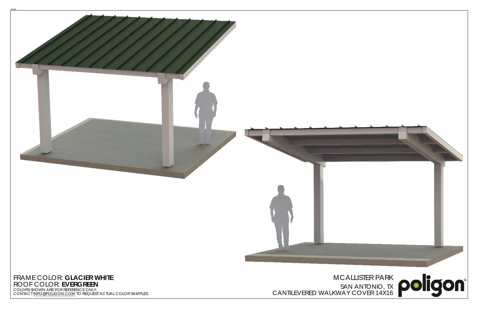
FRAME COLOR: GLACIER WHITEROOF COLOR: EVERGREENCOLORS SHOWN ARE FOR REFERENCE ONLY. CONTACT [email protected] TO REQUEST ACTUAL COLOR SAMPLES.
MCALLISTER PARKSAN ANTONIO, TX
CANTILEVERED WALKWAY COVER 14X16
2014A

Addendum No. 04
Attachment 3

City of San Antonio 2012-2017 Bond Program 107300.2 – Page 1 of 6 McAllister Park, WBS No. 40-00375
February 11, 2015 SPECIALTIES MANUFACTURER OF PROTECTIVE COVERS 107300.2 - 1
DIVISION 107300.2
SPECIALTIES MANUFACTURER OF PROTECTIVE COVERS Icon Shelter Systems Inc. (or approved equal)
PART 1 – GENERAL
1.1 DESCRIPTION OF PRODUCT A. Shelter Type: 14’x 16 Monoslope Cantilever style shelter with Standing Seam roof
panels. B. Roof Slope: 2:12 C. Clear height under Tie Beam (UTB): 8’-0”. This is the clearance under the tie beam which
spans between the columns.
1.2 REFERENCES A. Referenced Standards
1. AISC – American Institute of Steel Construction a. AISC Steel Construction Manual – 14th edition b. AISC 360-10 Specification for Structural Steel Buildings
2. ASTM – American Society for Testing and Materials a. ASTM A36/A36M – Standard Specification for Carbon Structural Steel; 2008 b. ASTM A325 – Standard Specification for Structural Steel Bolts, Heat Treated,
120/105 ksi Minimum Tensile Strength; 2010 c. ASTM A563 – Standard Specification for Carbon and Alloy Steel Nuts; 2007a d. ASTM A500 – Standard Specification for Cold-Formed Welded and Seamless
Carbon Steel Structural Tubing in Rounds and Shapes; 2010a e. ASTM A653/A653M – Standard Specification for Sheet Steel, Zinc-Coated
(Galvanized) or Zinc-Iron Alloy Coated (Galvanealed) by the Hot Dip Process; 2010 f. ASTM A792/A792M – Standard Specification for Steel Sheet, 55% Aluminum-Zinc
Alloy Coated by the Hot-Dip Process; 2010 g. ASTM F1554 – Standard Specification for Anchor Bolts, Steel, 36, 50 and 105 ksi
Yield Strength; 2007a 3. AWS – American Welding Society
a. D1.1 b. D1.3 c. D1.8
4. OSHA – Occupational Safety and Health Administration a. Steel Erection Standard 29 CFR 1926.750 Part R
5. SSPC – Steel Structures Painting Council a. SSPC-SP 2 – Hand Tool Cleaning; 2004 b. SSPC-SP 10/NACE No. 2 – Near White Blast Cleaning; 2007
6. LEED – Leadership in Energy and Environmental Design 7. ISO – International Organization for Standardization
1.3 SYSTEM DESCRIPTION
A. The structure shall be a pre-engineered package and shall be shipped as a pre-cut (excluding standing seam roof panels) and pre-fabricated package that shall include the structural framing members, roof panels, fasteners and roof trim as well as job specific installation instructions. The structure will be shipped in an un-assembled package for ease of shipment and minimum shipping charges.
1.4 SUBMITTALS A. Submit a minimum of four (4) sets of submittal drawings and (2) sets of structural calculations
signed and sealed by a Professional Engineer licensed in the state of Texas. B. Product Design Requirements:

City of San Antonio 2012-2017 Bond Program 107300.2 – Page 2 of 6 McAllister Park, WBS No. 40-00375
February 11, 2015 SPECIALTIES MANUFACTURER OF PROTECTIVE COVERS 107300.2 - 2
1. The structure shall meet the following design requirements a. Building Code: IBC 2009 b. Ground Snow Load: 20 c. Live Load: 20 d. Wind Speed: 90 e. Seismic Design Category: D
C. Submittal Requirements 1. Calculations:
a. Design according to the requirements of the national, state or local building codes as indicated in Section 1.04.B.
b. Calculations shall include all member design for each different member type. c. Connection design for each different connection that will determine the design of the
bolts, welds, plate thickness and anchorage to the foundation. d. Foundation design shall be for the loads applied and not a generic foundation design,
taking into account all soils information. 2. Submittal Drawings:
a. Anchor bolt layout with all appropriate dimensions for installation. b. Site specific foundation design. c. Isometric as well as elevation and plan views of the farming members along with the
member sizes and locations indicated on the drawings. d. Connection details for every connection on the frame. e. Roof panel connections and trim installation details. f. All accessories on the structure shall have an installation detail as well as connection
details. D. Foundation Design
1. The foundation design shall be supplied by the manufacturer. 2. Anchor bolts shall be supplied by the manufacturer. 3. Foundation materials and labor shall be provided by the structure contractor. 4. Owner should provide site specific soils information for proper foundation design, if that
data is not provided the foundation will be design for the minimum soil values allowed by code.
1.5 QUALITY ASSURANCE A. Manufacturer Qualifications
1. The product shall be designed, engineered and fabricated at a facility operated and directly supervised by the manufacturer.
2. The manufacturer shall have a minimum of 9 years in steel shelter fabrication. 3. Full Time on Staff Quality Assurance Manager. 4. All welders must be AWS certified for welding steel structures. 5. Membership in the American Welding Society (AWS). 6. Membership in the American Institute of Steel Construction (AISC). 7. Full Time on Staff Licensed Engineer. 8. Published Quality Control System manual. 9. Quality Control System must pass an annual audit by a Third Part Agency. 10. ISO 9001 certification for Powder Coating System.
B. Manufacturer’s Certifications 1. Clark County, NV Approved Fabricator. 2. City of Riverside, CA Approved Fabricator. 3. City of Houston, TX Approved Fabricator Structural Steel.
1.6 FIELD OR SITE CONDITIONS
A. Foundations shall be installed per the ICON installation drawings. 1. All foundations shall be cast at the same elevation unless specifically noted on the ICON
installation drawings. B. Anchor bolts shall be placed in the foundation as per the ICON installation drawings utilizing
the anchor bolt template supplied with the anchor bolts.

City of San Antonio 2012-2017 Bond Program 107300.2 – Page 3 of 6 McAllister Park, WBS No. 40-00375
February 11, 2015 SPECIALTIES MANUFACTURER OF PROTECTIVE COVERS 107300.2 - 3
1. Anchor bolts shall be installed per the dimensions and orientation shown on the drawings.
1.7 MANUFACTURER WARRANTY A. Shelter shall have a 10 year limited warranty on the steel framing members. B. Shelter shall have a 10 year limited warranty on the powder-coated elements. C. For all Metal Roofing there will be a pass through warranty direct from the metal Roofing
supplier, warranty shall be provided on request.
PART 2 – PRODUCTS
2.1 SHELTER SYSTEM AND MATERIALS A. Manufacturers:
1. Acceptable Manufacturer: ICON Shelter Systems, Inc., 1455 Lincoln Rd., Holland, MI, 49423. Email: [email protected], Website: www.iconshelters.com.
2. Pricing for this specific project and specified shelter can be requested from: The Playwell Group 4743 Iberia Avenue Suite C Dallas, TX 75207 Ph: 972-488-9355 Fax: 972-488-0642
3. The product shall be designed and fabricated at a facility operated and directly supervised by the manufacturer.
B. Substitution Limitations: 1. Substitutions must be approved a minimum of ten (10) business days prior to bid. All
approved manufacturers shall be notified on writing before the bid date and shall not be allowed to bid without written notification. Any approval of an alternate manufacturer shall be through and official bid addendum prior to the bid date.
2. Alternate suppliers shall meet the requirements, qualifications and provide proof of certifications listed under Section 1.05 QUALITY ASSURANCE.
3. Alternate suppliers shall provide documentation that the power-coat system being provided meets or exceeds the ICON supplied powder-coat system listed under Section 2.01(c)(8).
C. Product Requirements and Materials: 1. General
a. The pre-engineered and pre-fabricated package of parts shall be pre-cut and packaged unless noted otherwise. These packages will include all parts and pieces necessary to field assemble the shelter at the jobsite. The shelter shall be shipped in knocked down format to minimize shipping expenses. Field labor will be kept to a minimum with no on-site welding required.
2. Concrete for Foundations a. Concrete shall have a minimum 28-day compressive strength of 2,500 psi unless
noted otherwise on the foundation detail. b. Reinforcing steel shall be ASTM A615, Grade 60.
3. Columns a. Hollow Structural Section (HSS) columns shall meet ASTM A500, Grade B with a
minimum wall thickness of 3/16” (0.1875”). b. Unless the columns are direct buried in the foundation the columns shall attach to the
foundation with a minimum of four (4) anchor rods and shall meet OSHA Steel Erection Standard 29 CFR 1926.755(a)(1).
4. Structural Framing a. All Hollow Structural Sections (HSS) shall meet ASTM A500, Grade B. “I” Beams,
tapered columns or open channel sections shall not be accepted for primary members.
5. Compression Rings

City of San Antonio 2012-2017 Bond Program 107300.2 – Page 4 of 6 McAllister Park, WBS No. 40-00375
February 11, 2015 SPECIALTIES MANUFACTURER OF PROTECTIVE COVERS 107300.2 - 4
a. Compression rings shall be made of ASTM A36 structural plate or of structural channel welded together to form the ring. All connections not requiring compression rings shall use ASTM A500, Grade B HSS sections for these connections.
6. Connection Requirements a. Anchor rods shall be ASTM F1554, Grade 36 unless otherwise noted. b. Structural fasteners shall be ASTM A325 high strength bolts and A563 nuts. c. All structural fasteners shall be hidden within the framing members whenever
possible. d. No field welding shall be required to finish the construction of the shelter. e. Manufacturer shall supply extra fasteners.
7. Roofing Materials a. PRIMARY ROOF DECK – MEDALLION-LOK STANDING SEAM ROOFING
(1) Roofing shall be a minimum of 24 gauge Galvalume steel sheet with ribs that are 1 3/4” tall and the panels are 16” wide. Ribs shall run with the slope of the roof for proper drainage.
(2) Roof outside surface shall be a baked on Kynar 500 paint finish and shall be supplied in one of the manufacturer’s standard colors: TBD. Ceiling color to be a “wash coat” primer.
(3) All roof panel angles shall be cut in the field. (4) Metal roofing trim shall match the color of the roof and shall be factory made from
26 gauge Kynar 500 painted Galvalume sheet steel. (5) Trim includes panel ridge caps, hip caps, eave “J” trim, splice channels, rake
trim, roof peak cap and corner trim as applicable for the model selected. Trim may need to be field cut to length. Please refer to the installation drawings for additional information and detail.
(6) Ridge, hip and valley caps shall be pre-formed with a single central bend to match the roof slope and shall be hemmed on both edges.
(7) Roof peak caps shall be pre-fabricated with no field assembly required. (8) Roofing is attached to sub-framing with clips.
8. Factory Frame Finish a. All structural steel shall be cleaned, pre-treated and finished in the following manner:
(1) The steel shall be shot-blasted to the specification of SSPC-SP10 near white blast cleaning. SSPC-SP2 hand tool cleaning will not be an acceptable alternative.
(2) The shot-blasted parts are then washed with zinc-phosphate in an eight (8) stage washer.
(3) The steel is then immersed in a liquid epoxy and coated through an electro-deposition process (E-coat), this is coated both inside and out to a uniform cover of 0.7-0.9 mils. The E-coat totally encapsulates the part for superior corrosion protection.
(4) The parts are then coated with a color coat of TGIC polyester powder and then one clear coat for a final finish thickness of 8 to 12 mils.
9. Factory Prime Paint a. All steel shall be cleaned to the specification of SSPC-SP2 (Hand Tool cleaning) or
better. This removes all loose mill scale, loose rust and any other loose foreign matter. The clean steel will then be primed with a quick dry, lead and chromate free alkyd primer.
10. Accessories a. Electrical Access
(1) Standard in all column bases is a 1 3/4" diameter hole, located in the center of the plate. This allows electrical wiring into the column base.

City of San Antonio 2012-2017 Bond Program 107300.2 – Page 5 of 6 McAllister Park, WBS No. 40-00375
February 11, 2015 SPECIALTIES MANUFACTURER OF PROTECTIVE COVERS 107300.2 - 5
PART 3 - EXECUTION
3.1 STORAGE AND HANDLING A. When the shelter arrives at the jobsite protect the products from weather, sunlight and
damage. B. When unloading, pad the forks and use other precautions to protect the powder-coated finish.
Do not use chains to move the materials, use straps. Handle all materials carefully in the field to avoid scratching the powder-coat finish.
C. Contractor shall store the product elevated from the soil to allow full air circulation around the materials as do not introduce mold, decay, fungi or insects into or on the materials. One end of the materials shall be elevated higher than the other end if storage will be longer than a few days as to allow the water to run off the materials.
3.2 INSTALLATION OF MATERIALS A. The shelter shall be placed on prepared foundations that were designed by the manufacturer
(unless otherwise noted). Materials for these foundations are not supplied by ICON but by the foundation installation contractor. Foundation shall be constructed to all local building code requirements and per good construction practices for the specific site conditions. 1. In accordance with OSHA Steel Erection Standard 29 CFR 1926.750 Part R, anchor rods
shall be installed for proper column stability and shall have a minimum of four (4) anchor bolts per column. Therefore no single anchor rod column base connections shall be allowed.
B. Install all parts and pieces per the manufacturer’s supplied installation instructions and these specifications.
C. The interface with other work required is to be coordinated by the customer or the customer’s agent. Some design may have electrical or plumbing requirements that are not supplied by ICON.
D. Tolerances on structural steel members are set according to AISC Code of Standard Practice for Steel Buildings and Bridges and have been used for the fabrication of this product. These tolerances will not and cannot be increased. No field slotting or opening of holes will be allowed without proper guidance from the ICON Engineering Department.
3.3 REPAIR A. No field modifications or corrections are allowed without authorization from the ICON
Engineering Department.
3.4 SITE QUALITY CONTROL B. ICON does not require any on-site inspections or testing but these may be required by local
authorities and the local building inspector. Please be aware of any on-site requirements prior to starting installation.
END OF SECTION

Addendum No. 04
Attachment 4


![RAVI COLTRANE: QUARTET – Contract Rider: Quartet: Ravi ...P... · RAVI COLTRANE: QUARTET – Contract Rider: [Current: May 2012] Quartet: Ravi Coltrane (Saxophone) + Guitar, Bass,](https://static.fdocuments.net/doc/165x107/5ab9fb537f8b9a28468eab6a/ravi-coltrane-quartet-contract-rider-quartet-ravi-pravi-coltrane.jpg)