Collimator-Induced Defects In Planar and SPECT …tech.snmjournals.org/content/23/3/167.full.pdf ·...
7
Collimator-Induced Defects In Planar and SPECT Gamma Camera Images: A Multicenter Study Michael J. Blend, Bhupendra A. Patel and Ernest Byrom Section of Nuclear Medicine, University of Illinois Hospital at Chicago; Division of Nuclear Medicine, Michael Reese Hospital, Chicago; and Division of Cardiology, The Evanston Hospital, Evanston, Illinois Objective: Optimized nuclear medicine imaging requires that collimator uniformity be as good as the corrected uniformity of the camera. In the past we have observed multiple artifacts with high-resolution foil but not with the high-resolution cast collimators. The purpose of our study was to determine if these collimator artifacts could be observed in other institu- tions using a variety of gamma cameras and collimators. Methods: Ten medical centers in the Chicago area partici- pated. Planar images of a 5-mCi (185-MBq) point source of 99 '"Tc placed 5 m from the collimator face were obtained. Additional planar images of line sources placed at 0, 5, 1 0, 15, 20, 25 and 30 em from the collimator face were also obtained. Tomographic images of a single SPECT phantom were acquired from five of the institutions under a defined protocol. Results: With one exception, the 5-m point source images with low-energy high-resolution foil collimators (HRFC) dem- onstrated linear hot and cold streak artifacts, whereas low- energy high-resolution cast collimators (HRCC) did not. Un- ear defects were also present in the line source images at distances of 15 to 30 em from the HRFC face but were absent or much less prominent with the HRCC. These foil-generated defects were not observed in one brand of HRFC, which may be related to the method of manufacturing. With the excep- tion of this same manufacturer of HRFC, ring artifacts were noted in SPECT reconstructed images with HRFC-acquired data but not with HRCC-acquired data. Conclusion: These findings illustrate the importance of properly evaluating the uniformity of each collimator pur- chased with any new camera system. Key Words: collimator artifacts; testing collimator perfor- mance; quality control J Nucl Med Techno/1995; 23:167-172 It has been well established that a systematic and compre- hensive quality control program for gamma cameras is es- sential to maximize the information that can be derived from diagnostic studies in nuclear medicine. Achieving and main- For correspondence and reprints contact: Michael J. Blend, PhD, DO, Section of Nuclear Medicine (M/C 931), University of Illinois Hospital, 1740 West Taylor Ave., Chicago, IL 60612. VOLUME 23, NUMBER 3, SEPTEMBER 1995 taining the best possible imaging results from a gamma cam- era system can be assured only through the appropriate use of periodic performance testing. Extensive acceptance test- ing should occur at the time of installation. Routine testing (daily, weekly), and extended testing (monthly, quarterly, and at times of upgrades or repairs) should be a standard requirement in any nuclear medicine quality control program (J-2). The collimator is the first part of a gamma camera to receive photons from a patient or a test source. A collimator is a device which consists of one or more holes in a dense material of high atomic number (such as lead or tungsten) that is almost opaque to the gamma photons encountered in nuclear medicine. Attached to a radiation detector and used for radionuclide imaging, the collimator performs the same function as the lens of a camera. It delineates the field of view and only allows those gamma rays traveling in a certain direction to strike the crystal. Similar to a lens, a collimator can affect the sensitivity, spatial resolution, and depth of field of the imaging instrument. Optimized imaging requires that collimator uniformity be as good as the corrected uniformity of the gamma camera. Imperfections such as septal tears, improper alignment of channels, and improper seating can be built into collimators at the time of manufacture. Impact damage during shipping and daily use can also cause imperfections in a collimator that can induce artifacts in the final images. Often these types of defects cannot be detected with a routine sheet source flood image. SPEer gamma cameras place more stringent require- ments on system performance, including the uniformity ob- tained with a collimator in place (extrinsic uniformity). Mod- ern SPEer gamma cameras achieve their improved images by enhancing uniformity and spatial linearity through digital correction techniques (for energy, linearity and uniformity). Collimator nonuniformities can be amplified during SPEer reconstruction and may lead to major artifacts that might not be apparent with planar imaging. When the perpendicular alignment between the collimator face and the collimator holes for parallel-hole collimators is not perfect, changes in center of rotation (COR) calculation across the field of view 187 by on August 26, 2018. For personal use only. tech.snmjournals.org Downloaded from
Transcript of Collimator-Induced Defects In Planar and SPECT …tech.snmjournals.org/content/23/3/167.full.pdf ·...

Collimator-Induced Defects In Planar and SPECT Gamma Camera Images: A Multicenter Study
Michael J. Blend, Bhupendra A. Patel and Ernest Byrom
Section of Nuclear Medicine, University of Illinois Hospital at Chicago; Division of Nuclear Medicine, Michael Reese Hospital, Chicago; and Division of Cardiology, The Evanston Hospital, Evanston, Illinois
Objective: Optimized nuclear medicine imaging requires that collimator uniformity be as good as the corrected uniformity of the camera. In the past we have observed multiple artifacts with high-resolution foil but not with the high-resolution cast collimators. The purpose of our study was to determine if these collimator artifacts could be observed in other institutions using a variety of gamma cameras and collimators. Methods: Ten medical centers in the Chicago area participated. Planar images of a 5-mCi (185-MBq) point source of 99'"Tc placed 5 m from the collimator face were obtained. Additional planar images of line sources placed at 0, 5, 1 0, 15, 20, 25 and 30 em from the collimator face were also obtained. Tomographic images of a single SPECT phantom were acquired from five of the institutions under a defined protocol. Results: With one exception, the 5-m point source images with low-energy high-resolution foil collimators (HRFC) demonstrated linear hot and cold streak artifacts, whereas lowenergy high-resolution cast collimators (HRCC) did not. Unear defects were also present in the line source images at distances of 15 to 30 em from the HRFC face but were absent or much less prominent with the HRCC. These foil-generated defects were not observed in one brand of HRFC, which may be related to the method of manufacturing. With the exception of this same manufacturer of HRFC, ring artifacts were noted in SPECT reconstructed images with HRFC-acquired data but not with HRCC-acquired data. Conclusion: These findings illustrate the importance of properly evaluating the uniformity of each collimator purchased with any new camera system. Key Words: collimator artifacts; testing collimator performance; quality control
J Nucl Med Techno/1995; 23:167-172
It has been well established that a systematic and comprehensive quality control program for gamma cameras is essential to maximize the information that can be derived from diagnostic studies in nuclear medicine. Achieving and main-
For correspondence and reprints contact: Michael J. Blend, PhD, DO, Section of Nuclear Medicine (M/C 931), University of Illinois Hospital, 1740 West Taylor Ave., Chicago, IL 60612.
VOLUME 23, NUMBER 3, SEPTEMBER 1995
taining the best possible imaging results from a gamma camera system can be assured only through the appropriate use of periodic performance testing. Extensive acceptance testing should occur at the time of installation. Routine testing (daily, weekly), and extended testing (monthly, quarterly, and at times of upgrades or repairs) should be a standard requirement in any nuclear medicine quality control program (J-2).
The collimator is the first part of a gamma camera to receive photons from a patient or a test source. A collimator is a device which consists of one or more holes in a dense material of high atomic number (such as lead or tungsten) that is almost opaque to the gamma photons encountered in nuclear medicine. Attached to a radiation detector and used for radionuclide imaging, the collimator performs the same function as the lens of a camera. It delineates the field of view and only allows those gamma rays traveling in a certain direction to strike the crystal. Similar to a lens, a collimator can affect the sensitivity, spatial resolution, and depth of field of the imaging instrument.
Optimized imaging requires that collimator uniformity be as good as the corrected uniformity of the gamma camera. Imperfections such as septal tears, improper alignment of channels, and improper seating can be built into collimators at the time of manufacture. Impact damage during shipping and daily use can also cause imperfections in a collimator that can induce artifacts in the final images. Often these types of defects cannot be detected with a routine sheet source flood image.
SPEer gamma cameras place more stringent requirements on system performance, including the uniformity obtained with a collimator in place (extrinsic uniformity). Modern SPEer gamma cameras achieve their improved images by enhancing uniformity and spatial linearity through digital correction techniques (for energy, linearity and uniformity). Collimator nonuniformities can be amplified during SPEer reconstruction and may lead to major artifacts that might not be apparent with planar imaging. When the perpendicular alignment between the collimator face and the collimator holes for parallel-hole collimators is not perfect, changes in center of rotation (COR) calculation across the field of view
187
by on August 26, 2018. For personal use only. tech.snmjournals.org Downloaded from

will result (3). Electronic correction programs built into a gamma camera system may be inadequate for SPEer imaging when the collimator itself introduces a significant degree of nonuniforrnity. Even when a high-quality extrinsic uniformity image is obtained with a 57Co sheet source, collimator defects can still induce errors in the final planar and SPEer images.
As part of our standard acceptance testing procedure for a new SPEer gamma camera system, we observed multiple image artifacts with a high-resolution foil but not with a high-resolution cast collimator when data was acquired from a distant point source and from line sources at clinically significant distances (I). We concluded that these defects were the result of differences in manufacturing technique and design. Our purpose in this study was to determine if these same image defects could be observed in other institutions in a consistent manner using a variety of SPEer gamma camera systems and collimators from various manufacturers. We present simple quality control procedures for examining collimator performance at the time of acceptance testing. These tests do not require specialized equipment for analysis. There are additional quantitative and qualitative collimator performance tests that can be performed which require special equipment and some of these techniques are discussed in this paper. The reader is also referred to several review articles for a more complete coverage of this topic ( 4-6).
MATERIALS AND METHODS
Ten medical centers in the Chicago area participated in the study (see Appendix A). Five of the institutions were academic medical centers and the remaining institutions were large community hospitals. Hospital size ranged from 350 to 980 beds. Nine of the 10 centers had at least one HRFC and one HRCC in routine use during the time of this study. One large institution had only HRFCs of varying ages on hand. However, their newest foil collimator was constructed by a different (semi-automated) manufacturing process. This new process for manufacturing foil collimators was designed to improve collimator uniformity and, for this reason, this institution was included in the study.
Each institution was given an identical set of test instructions to perform on their camera systems. The tests were performed on two separate days. The first set of tests involved planar imaging of a distant source and line sources. All 10 institutions completed this portion of the study without difficulty or protocol violations. The second set of tests involved acquisition of data from a single SPEer phantom and only 5 institutions completed this portion of the study successfully. One of the authors traveled to each institution to supervise and help perform the tests as described in the instructions. We also provided the line source pipettes and the SPEer phantom for use at each institution.
A total of 9 HRCCs and 11 HRFCs were tested on 7 models of gamma cameras made by 5 different manufacturers in the 10 institutions. Ten of the 11 HRFCs were at least 3 yr old and all passed standard daily uniformity testing as
168
prescribed by the individual institution. One HRFC had been recently purchased with a new SPEer system and was constructed using a different method. This new process involved a semi-automated high-pressure system of construction and will be discussed later in this paper.
Intrinsic uniformity correction maps were acquired at each institution using the camera manufacturer's suggested protocol. Uniformity maps of 99 million count acquisition with a 57Co uniformity sheet source at the surface of the collimator were obtained in all but one institution. Separate uniformity correction maps were created for each collimator tested in this study using the same 57Co sheet source on the day of testing. All tomographic images were corrected with the appropriate uniformity matrices and displayed for visual examination. All planar and SPECT images were inspected for regions of non uniformity, ring artifacts and linear defects.
Initially, planar images of a 5-rnCi point source of 99mTc placed 5 m from the collimator face in the center of the field were obtained. Additional planar images of 8 line sources made with 10-rnl plastic pipette tubes (8-rnrn diameter) filled with a solution containing 100 ,...ci of 99mTc diluted with 10 rnl of water were obtained. Care was taken to assure that all air bubbles were released from the pipettes before sealing and mounting. These line sources were mounted on a flat sheet of cardboard for support and placed on a patient imaging table. One-million count images were obtained using a 128 x 128 acquisition matrix which yields a pixel size of approximately 3.1 rnrn. Images were obtained with the camera above and below the patient table with line sources at distances of 5, 10, 15, 20, 25 and 30 ern from the collimator face. These distances were chosen as representative of clinically significant ranges. The camera was placed both above and below the patient table to check for any unexpected attenuation effects which may be relevant to SPEer image processing.
SPEer images were obtained using a single Data General SPEer Phantom (Atomic Products Corporation, Shirley, NY) that was supplied to each institution participating in this portion of the study. The phantom was filled to capacity with water containing 10 rnCi of 99mTc and placed on the imaging table. Again, care was taken to remove gas bubbles from the phantom before sealing and imaging. The projection images were acquired in a 128 x 128 matrix for a 40-sec counting period for each of 60 to 64 steps (depending on the particular gamma camera system), with the phantom at the same distance from the camera for both foil and cast collimators. Transaxial images were reconstructed using a Ramp filter, both with and without prefiltering by a Hanning filter with a 1.0 cycles/em cutoff, and post-processing attenuation correction using a 0.12 crn- 1 attenuation coefficient. Images from both collimator designs were displayed as slices of 1 or 2 pixels thick for visual inspection.
Tests were performed and data collected over an 8-rnonth period and analyzed by the authors. Extrinsic uniformity of a point source, line sources and tomographic images of a single phantom were all visually inspected and results were
JOURNAL OF NUCLEAR MEDICINE TECHNOLOGY
by on August 26, 2018. For personal use only. tech.snmjournals.org Downloaded from

FIGURE 1. Two high-count images (99 k) of a 57 Co uniformity sheet source placed at the collimator surface. Image (A) was obtained with an HRFC and image (B) an HFCC. Significant differences between the two images were not visually appreciated. This was a consistent finding among the 1 0 institutions.
tabulated. If protocol violations were detected, the test was repeated at the participating institution.
RESULTS
Figure 1 demonstrates two high-count images (99 million) of a single 57 Co sheet source; image (A) was obtained with an HRFC in place and image (B) was obtained with an HRCC. Visual inspection failed to reveal any significant differences in uniformity between the two images. This was a consistent pattern noted at all the institutions using either a cast or foil collimator and a high-count 57Co sheet source.
Figure 2 shows a planar image of a distant point source obtained with an HRCC (A), and a similar image obtained with an HRFC (B). This example is one of the worst case displays we noted when a single-point source was placed 5 m from the collimator face in the center of the field. These
FIGURE 2. Two planar images of a distant point source at 5 m from the collimator face in the center of the field. Image (A) was obtained with an HRCC, and image (B) with an HRFC. Note linear defects in the foil collimator image.
YOLUMI! 23, NUMBER 3, SEPTEMBER 1995
FIGURE 3. Two planar images of a distant point source at 5 m from the collimator face. Image (A) was obtained with an HRFC constructed by a new semi-automated manufacturing process. Image (B) was obtained with an HRFC constructed by the standard method. Note the vast differences in uniformity between images A and B.
images represent crude radiographs of the collimators, revealing multiple linear defects in the HRFC image but not in the HRCC image. In 9 of 10 institutions, hot and cold linear artifacts were seen with the HRFC and not with the HRCC. All institutions that used the standard HRFCs demonstrated linear artifacts. At the one institution where the two HRFCs tested were from the same manufacturer, linear artifacts were noted on the standard HRFC but not in the new foil collimator made by a semiautomated process. Figure 3 presents two planar images of a distant point source at 5 m from the collimator face. Figure 3A was obtained with an HRFC constructed by a new semiautomated manufacturing process. Figure 3B was obtained with an HRFC constructed by the standard method. The point source images obtained with the HRFC constructed by the new semi-automated process demonstrated a similar uniformity pattern as those obtained with HRCCs.
Multiple line sources were set diagonally in the field of view of the gamma cameras in order to avoid source alignment with the previously noted linear artifacts in the point source images. HRFC images demonstrated horizontal cold linear artifacts crossing the diagonal lines in images at 15, 20, 25 and 30 em from the face of the camera. Similar artifacts were not seen in the HRCC images at these distances. These artifacts were consistently seen in all institutions using the HRFCs and are similar to the artifacts illustrated in our previous work (1 ). Figures 4 and 5 show planar images of multiple line sources placed at 0, 5, 10, 15, 20 and 25 em from the collimator face using the new semi-automated HRFC (Fig. 4) and the standard HRFC (Fig. 5). Again, the new HRFC model did not demonstrate cold linear defects in the line source images.
Reconstructed SPECT phantom images of data collected with HRFC and HRCC showed consistent differences. Figures 6 and 7 demonstrate multiple 2-pixel thick transaxial slices through the Data General SPECT Phantom from one institution. Multiple artifacts in slices 1 to 5 (Fig. 6A), and 22 to 30 (Fig. 6B) were noted. No ring artifacts were observed when an HRCC was used (Fig. 7A, B). These ring artifacts are seen only with the HRFCs and are more apparent on the images reconstructed after prefiltering. These defects are not seen when the HRCC or recent model machine-made HRFC were used. As with the planar artifacts, there is consistent visualization of ring artifacts in a comparable number of
169
by on August 26, 2018. For personal use only. tech.snmjournals.org Downloaded from
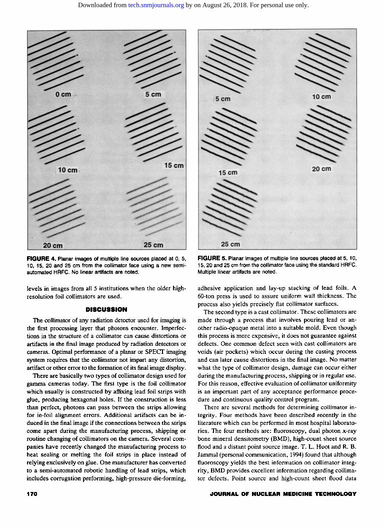
FIGURE 4. Planar images of multiple line sources placed at 0, 5, 10, 15, 20 and 25 em from the collimator face using a new semiautomated HRFC. No linear artifacts are noted.
levels in images from all 5 institutions when the older highresolution foil collimators are used_
DISCUSSION
The collimator of any radiation detector used for imaging is the first processing layer that photons encounter_ Imperfections in the structure of a collimator can cause distortions or artifacts in the final image produced by radiation detectors or cameras. Optimal performance of a planar or SPEer imaging system requires that the collimator not impart any distortion, artifact or other error to the formation of its final image display.
There are basically two types of collimator design used for gamma cameras today. The first type is the foil collimator which usually is constructed by affixing lead foil strips with glue, producing hexagonal holes. If the construction is less than perfect, photons can pass between the strips allowing for in-foil alignment errors. Additional artifacts can be induced in the final image if the connections between the strips come apart during the manufacturing process, shipping or routine changing of collimators on the camera. Several companies have recently changed the manufacturing process to heat sealing or melting the foil strips in place instead of relying exclusively on glue. One manufacturer has converted to a semi-automated robotic handling of lead strips, which includes corrugation preforming, high-pressure die-forming,
170
FIGURE 5. Planar images of multiple line sources placed at 5, 10, 15, 20 and 25 em from the collimator face using the standard HRFC. Multiple linear artifacts are noted.
adhesive application and lay-up stacking of lead foils. A 60-ton press is used to assure uniform wall thickness. The process also yields precisely flat collimator surfaces.
The second type is a cast collimator. These collimators are made through a process that involves pouring lead or another radio-opaque metal into a suitable mold. Even though this process is more expensive, it does not guarantee against defects. One common defect seen with cast collimators are voids (air pockets) which occur during the casting process and can later cause distortions in the final image. No matter what the type of collimator design, damage can occur either during the manufacturing process, shipping or in regular use. For this reason, effective evaluation of collimator uniformity is an important part of any acceptance performance procedure and continuous quality control program.
There are several methods for determining collimator integrity. Four methods have been described recently in the literature which can be performed in most hospital laboratories. The four methods are: fluoroscopy, dual photon x-ray bone mineral densitometry (BMD), high-count sheet source flood and a distant point source image. T. L. Huot and R. B. Jammal (personal communication, 1994) found that although fluoroscopy yields the best information on collimator integrity, BMD provides excellent information regarding collimator defects. Point source and high-count sheet flood data
JOURNAL OF NUCLEAR MEDICINE TECHNOLOGY
by on August 26, 2018. For personal use only. tech.snmjournals.org Downloaded from

FIGURE 6. Multiple reconstructed transaxial images of a SPECT phantom acquired with an HRFC. Ring artifacts in slices 1 to 5 (A) and 22 to 30 (B) were seen. Similar ring artifacts were noted at the end slices of the phantom images in all five institutions when data were acquired with the standard HRFC.
collecting provide adequate information regarding the absence or presence of collimator damage.
One of the objectives of this study was to use simple tests for collimator uniformity that did not require special equipment. Fluoroscopy would have required the transportation of collimators outside the nuclear medicine section in most of our hospitals. The number of films necessary to image the entire collimator, as well as the distortion seen along the edges of the films due to the fanning of the beam with fluoroscopy, suggested that this procedure would not be feasible or easy to perform. Many of the institutions, including our own, did not have a dual photon x-ray bone mineral densitometer available for use. For these reasons, we chose to use a distant point
source, high-count sheet source imaging, and line source imaging at clinically significant distances for testing collimator integrity.
The distant point source images constitute a crude radiograph of the collimator. They show the collimator at the intrinsic resolution of the gamma camera, just as a bar phantom is used with a distant point source to test the intrinsic resolution. The almost parallel rays from a point source at 5 m throw a shadow of the collimator on the crystal. Using a sheet source at the face of the collimator, in contrast, illuminates each part of the collimator with rays from a broad range of directions, so that many partial shadows overlap. The result is an image of the source blurred to the resolution
FIGURE 7. (A) Multiple reconstructed transaxial images of aSPECT phantom acquired with an HRCC are presented. (B) No ring artifacts were noted in any of the five institutions' images when a cast collimator was used.
VOLUME 23, NUMBER 3, SEPTEMBER 1995 171
by on August 26, 2018. For personal use only. tech.snmjournals.org Downloaded from

of the collimator, and any shadowing objects (whether external or collimator defects) are likewise seen at the collimator resolution. Thus, some defects visible with a distance point source are not seen with the sheet source.
This study is concerned with the effects of such collimator defects, visible with the point source but not with the sheet source. Using the point source, defects are consistently seen with the older high-resolution foil collimators that are not seen in high-resolution cast collimators. LEAP and mediumenergy parallel-hole collimators were not tested in this study. Clearly such defects are not corrected by the usual uniformity correction based on a sheet source at the collimator face. Thus they may affect clinical images and, in particular, projection images used in SPECT reconstruction.
The line source images indicate the depth at which the defects begin to have an effect. At 0 to 15 em from the collimator face defects are not visible, but at greater distances the line sources show cold artifacts when HRFCs are used. While these artifacts have not been identified in clinical planar images, where they may be obscured by multiple extended sources and background, they present problems for SPECT reconstruction which necessarily includes structures at distances greater than 15 em.
These artifacts are comparable to uncorrected nonuniformities in that they appear at the same place in the field of view in each of the 60 or 64 projection images. In transaxial reconstruction, the backprojection operation combines them into an annulus, centered on the axis of rotation. These ring artifacts (4) are much more prominent in transaxial sections than the original nonuniformities in the planar image. Thus, uncorrected collimator defects are of greatest concern for SPECT imaging.
When a SPECT phantom was imaged, ring artifacts did indeed appear whenever the collimator had defects revealed by the distant point source. Collimators without such distant point defects did not induce ring artifacts. For each collimator, the uniformity correction was made with that collimator in place. The uniformity correction removed the effects of everything apparent in the sheet source image, but not the effects apparent only with more distant sources, which remained to create ring artifacts in SPECT-reconstructed images.
CONCLUSION
The high-count flood sheet source data acquisition procedure appears to be the most commonly used performance test for collimator integrity. However, we found the distant point source and line source methods to be more sensitive tests of collimator integrity. These tests are simple and quick to perform and do not require any specialized equipment for test result analysis.
Our data showed that most high-resolution foil collimators introduce linear defects when acquiring data from a distant point source or line sources at 15 to 30 em. High-resolution cast collimators did not introduce these artifacts and that may be secondary to differences in the manufacturing process. These defects were invisible in high count images ob-
172
tained with a 57 Co sheet source at the face of the collimator. When line sources are used, linear cold defects were clearly visible in images obtained at clinically significant distances from the face of the collimator on planar views (15-30 em). This was a consistent finding in all institutions testing the older HRFCs. The defects in the line sources were not observed when HRCCs were used.
SPECT imaging at clinically significant distances demonstrated artifacts associated with non uniformity. These artifacts appear in the reconstructed images even though uniformity correction was performed using an image of a sheet source made with the same collimator.
The role of collimation in gamma camera systems is often overlooked. Some manufacturers tempt potential buyers to purchase their gamma camera system by providing sets of collimators free of charge. Potential buyers may think that any collimator design or less-than-optimal collimators will work well with the system they are about to purchase since they are being provided by the camera manufacturer. In fact, collimator defects can have such a dramatic influence on SPECT imaging that the concept of evaluating and purchasing them as a separate entity from the SPECT system is well worth considering. Evaluation of collimators at the time of acceptance testing should include images of a distant (5 m if possible) point source, and line sources at clinically significant differences away from the face of the collimator.
APPENDIX A PARTICIPATING MEDICAL INSTITUTIONS
Loyola University Medical Center, Maywood, IL The Children's Memorial Hospital, Chicago, IL Rush Presbyterian St. Luke Hospital, Chicago, IL Elmhurst Memorial Hospital, Elmhurst, IL St. James Hospital and Medical Center, Chicago Heights, IL Little Company of Mary Hospital, Evergreen Park, IL Doctors Hospital of Hyde Park, Chicago, IL Mount Sinai Hospital, Chicago, IL Michael Reese Hospital, Chicago, IL University of Illinois Hospital, Chicago, IL
REFERENCES
I. Blend MJ, Patel BA, Rubas D, et al. Foil collimator defects: a comparison with cast collimators. J Nuc/ Med Techno/ 1992;20:18-22.
2. Ficken V and McCartney W. SPEer quality control: a program recom
mended by the American College of Nuclear Physicians and the ACNP Corporate Committee. J Nuc/ Med Techno/ 1994;22:205-210.
3. Rogers WL, Clinthorne NH, Harkness BA, et al. Field-flood require
ments for emission computed tomography with an Anger camera. J Nuc/ Med 1982;23:162-168.
4. Jaszczak RJ, Coleman RE. Selected processing techniques for scintilla
tion camera based SPEer systems. In: Single-photon emission tomography and other selected computer topics. Proceedings of the lOth Annual Symposium. Miami Beach, FL: The Society of Nuclear Medicine Computer Council; 1980;45-49.
5. Chang W, Li SQ, Williams JJ, et al. New methods of examining gamma camera collimators. J Nuc/ Med 1988;29:676-683.
6. Malmin RE, Stanley PC, Guth WR. Collimator angulation error and its effect on SPEer. J Nuc/ Med 1990;31:655-659.
.JOURNAL OF NUCLEAR MEDICINE TECHNOLOGY
by on August 26, 2018. For personal use only. tech.snmjournals.org Downloaded from

1995;23:167-172.J. Nucl. Med. Technol. Michael J. Blend, Bhupendra A. Patel and Ernest Byrom Multicenter StudyCollimator-Induced Defects in Planar and SPECT Gamma Camera Images: A
http://tech.snmjournals.org/content/23/3/167This article and updated information are available at:
http://tech.snmjournals.org/site/subscriptions/online.xhtml
Information about subscriptions to JNMT can be found at:
http://tech.snmjournals.org/site/misc/permission.xhtmlInformation about reproducing figures, tables, or other portions of this article can be found online at:
(Print ISSN: 0091-4916, Online ISSN: 1535-5675)1850 Samuel Morse Drive, Reston, VA 20190.SNMMI | Society of Nuclear Medicine and Molecular Imaging
is published quarterly.Journal of Nuclear Medicine Technology
© Copyright 1995 SNMMI; all rights reserved.
by on August 26, 2018. For personal use only. tech.snmjournals.org Downloaded from


![arXiv:2005.12071v1 [physics.acc-ph] 25 May 2020a) b) e-Block collimator Block collimator (hidden) Wedge collimator Figure 2: 3D CAD model of the three collimator device. (a) The block](https://static.fdocuments.net/doc/165x107/5f99e989b5ff3471203ba93f/arxiv200512071v1-25-may-2020-a-b-e-block-collimator-block-collimator-hidden.jpg)