Code of Practice for the Design and Installation of Anchors
101
Code of Practice for the Design and Installation of Anchors
Transcript of Code of Practice for the Design and Installation of Anchors

Code of Practice for the Design and Installationof Anchors
Anchor cops cover revised.pdf 1 10/05/2010 18:29

Code of Practice for the Design and Installation of Anchors
Health and Safety Authority Page i
CONTENTS
1 FOREWORD ...............................................................................1
2 STATUS AND SCOPE OF THIS CODE OF PRACTICE .........................3
3 INTRODUCTION ..........................................................................9
4 DEFINITIONS .............................................................................13
5 BACKGROUND TO THE CONSTRUCTION PRODUCTS DIRECTIVE .......19
6 TYPES OF ANCHORS COVERED BY THIS CODE OF PRACTICE ..........23
7 ROLES AND RESPONSIBILITIES ..................................................29
8 DESIGN AND SPECIFICATION OF ANCHORS ..................................35
9 INFORMATION SUPPLIED BY ANCHOR MANUFACTURER/SUPPLIER ....56
10 INSTALLATION OF ANCHORS IN CONCRETE ...................................60
11 SUPERVISION AND INSPECTION OF ANCHORS .............................63
12 TESTING OF ANCHORS ..............................................................66
13 CERTIFICATION OF DESIGN AND INSTALLATION ...........................68
14 CHANGE MANAGEMENT — ALTERNATIVE ANCHORS ......................69
APPENDIX A: RECOMMENDED FORMS FOR THE DESIGN AND INSTALLATION OF ANCHORS ..71
APPENDIX B: EXAMPLE OF EUROPEAN TECHNICAL APPROVAL DOCUMENT (ETA) ................78
APPENDIX C: INFORMATION SOURCES .........................................................................92
Code of Practice for the Design and Installation of Anchors
Page Health and Safety Authorityii
Code of Practice for the Design and Installation of Anchors
Health and Safety Authority Section 1 | Page 1
1 FOREWORD
The Health and Safety Authority, with the consent of Dara Calleary TD, Minister Minister for Labour Affairs and for Public Service Transformation and following public consultation (including consultation with the statutory Advisory Committee on Construction Safety, referred to as the Construction Safety Advisory Committee, the Construction Industry Federation, the Irish Congress of Trade Unions and the general public), publishes this code of practice entitled Code of Practice for the Design and Installation of Anchors, in accordance with section 60 of the Safety, Health and Welfare at Work Act 2005.
The aim of this code of practice is to provide practical guidance to designers, specifiers and installers of metal anchors on the requirements and prohibitions set out in the relevant statutory provisions.
In particular, but not exclusively, this code of practice provides practical guidance as to the observance of the provisions of:
1. Chapter 1 of Part 2 (sections 8 to 12 in relation to the general duties of employers) and Chapter 2 of Part 2 (sections 13 to 15 in relation to the general duties of employees etc.) of the Safety, Health and Welfare at Work Act 2005 (No. 10 of 2005).
2. Part 2 (Regulations 6 to 23 in relation to design and management), Part 3 (Regulations 24 to 29 in relation to the general duties of contractors and others) and Part 4 (Regulation 30 in relation to site safety and access to construction sites, Regulation 35 in relation to protection from falling material and protective safety helmets, Regulation 40 in relation to lighting of workplaces, Regulation 42 in relation to projecting nails and loose material, Regulation 43 in relation to construction of temporary structures and Regulation 44 in relation to avoidance of danger from collapse of structure) of the Safety, Health and Welfare at Work (Construction) Regulations 2006 (S.I. No. 504 of 2006).
3. Chapter 2 of Part 2 (Regulations 27 to 61 in relation to the use of work equipment), Chapter 3 of Part 2 (Regulations 62 to 67 in relation to personal protective equipment), Part 3 (Regulations 74 to 93 in relation to electricity) and Part 4 (Regulations 94 to 119 in relation to work at height) of the Safety, Health and Welfare at Work (General Application) Regulations 2007 (S.I. No. 299 of 2007) as amended by the Safety, Health and Welfare at Work (General Application) (Amendment) Regulations 2007 (S.I. No. 732 of 2007).
This code of practice comes into operation on Monday 17th May 2010. Notice of publication of this code of practice was published in the Iris Oifigiúil of Friday 14th May 2010.
As regards the use of codes of practice in criminal proceedings, section 61 of the 2005 Act provides as follows:
61.(1) Where in proceedings for an offence under this Act relating to an alleged contravention of any requirement or prohibition imposed by or under a relevant statutory provision being a provision for which a code of practice had been published or approved by the Authority under section 60 at the
Code of Practice for the Design and Installation of Anchors
Section 1 | Page Health and Safety Authority2
time of the alleged contravention, subsection (2) shall have effect with respect to that code of practice in relation to those proceedings.
(2)(a) Where a code of practice referred to in subsection (1) appears to the court to give practical guidance as to the observance of the requirement or prohibition alleged to have been contravened, the code of practice shall be admissible in evidence.
(2)(b) Where it is proved that any act or omission of the defendant alleged to constitute the contravention—
(i) is a failure to observe a code of practice referred to in subsection (1), or
(ii) is a compliance with that code of practice, then such failure or compliance is admissible in evidence.
(3) A document bearing the seal of the Authority and purporting to be a code of practice or part of a code of practice published or approved of by the Authority under this section shall be admissible as evidence in any proceedings under this Act.
Robert RoeAssistant Chief Executive Officer and Secretary to the Board

Code of Practice for the Design and Installation of Anchors
Health and Safety Authority Section 2 | Page 3
2 STATUS AND SCOPE OF THIS CODE OF PRACTICE
This code of practice is published by the Health and Safety Authority in accordance with section 60 of the Safety, Health and Welfare at Work Act 2005. The code is intended to provide practical guidance on the procedures for safe design and installation of anchors in accordance with the Safety, Health and Welfare at Work (Construction) Regulations 2006 (S.I. No. 504 of 2006) as amended by the Safety, Health and Welfare at Work (Construction)(Amendment) Regulations 2008 (S.I. No. 130 of 2008) and Safety, Health and Welfare at Work (Construction)(Amendment)(No 2) Regulations 2008 (S.I. No. 423 of 2008), as well as relevant provisions of the Safety, Health and Welfare at Work Act 2005 (No. 10 of 2005) and the Safety, Health and Welfare at Work (General Application) Regulations 2007 (S.I. No. 299 of 2007) as amended by the Safety, Health and Welfare at Work (General Application) (Amendment) Regulations 2007 (S.I. No. 732 of 2007).
A failure to observe any part of this code of practice will not of itself render a person liable to civil or criminal proceedings. Where the code gives practical guidance on the observance of any of the relevant statutory provisions, then compliance or non-compliance with those provisions of the code may be admissible in evidence in any criminal proceedings.
You are not obliged to follow the practical guidance outlined in this code of practice or to complete of the various forms contained within. It may be acceptable for duty holders to take an alternative approach that deals with the relevant provisions covered in this code. In this case duty holders will need to satisfy themselves that their alternative approach is equivalent with that outlined in the code. However, a person who follows the approach outlined in this code will normally be doing enough to comply with legislation.
Part D of the Building Regulations (Amendment) (No. 2) Regulations 2000 (S.I. No. 249 of 2000) relates to materials and workmanship. In particular sections D1 and D3 are relevant to the design and installation of anchors:
D1 All works to which these Regulations apply shall be carried out with proper materials and in a workmanlike manner.
D3 In this Part “proper materials” means materials which are fit for the use for which they are intended and for the conditions in which they are to be used, and includes materials which—
(a) bear a CE Marking in accordance with the provisions of the Construction Products Directive; or
(b) comply with an appropriate harmonized standard, European technical approval or national technical specification as defined in article 4(2) of the Construction Products Directive; or
(c) comply with an appropriate Irish Standard or Irish Agrément Board Certificate or with an alternative national technical specification of any State which is a contracting part to the Agreement on the European Economic Area, which provides in use an equivalent level of safety and suitability.
Code of Practice for the Design and Installation of Anchors
Section 2 | Page Health and Safety Authority4
“Agreement on the European Economic Area” means the Agreement on the European Economic Area between the European Communities, their Member States and the Republic of Austria, the Republic of Finland, the Republic of Iceland, the principality of Liechtenstein, the Kingdom of Norway, the Kingdom of Sweden and the Swiss confederation, as published in the Official Journal of the European Communities (OJ L1/9 of 3 January, 1994).”
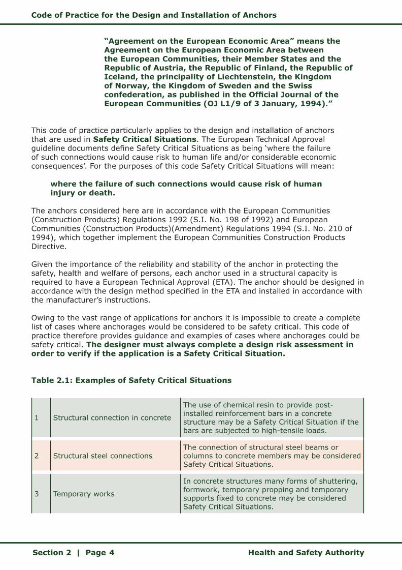
This code of practice particularly applies to the design and installation of anchors that are used in Safety Critical Situations. The European Technical Approval guideline documents define Safety Critical Situations as being ‘where the failure of such connections would cause risk to human life and/or considerable economic consequences’. For the purposes of this code Safety Critical Situations will mean:
where the failure of such connections would cause risk of human injury or death.
The anchors considered here are in accordance with the European Communities (Construction Products) Regulations 1992 (S.I. No. 198 of 1992) and European Communities (Construction Products)(Amendment) Regulations 1994 (S.I. No. 210 of 1994), which together implement the European Communities Construction Products Directive.
Given the importance of the reliability and stability of the anchor in protecting the safety, health and welfare of persons, each anchor used in a structural capacity is required to have a European Technical Approval (ETA). The anchor should be designed in accordance with the design method specified in the ETA and installed in accordance with the manufacturer’s instructions.
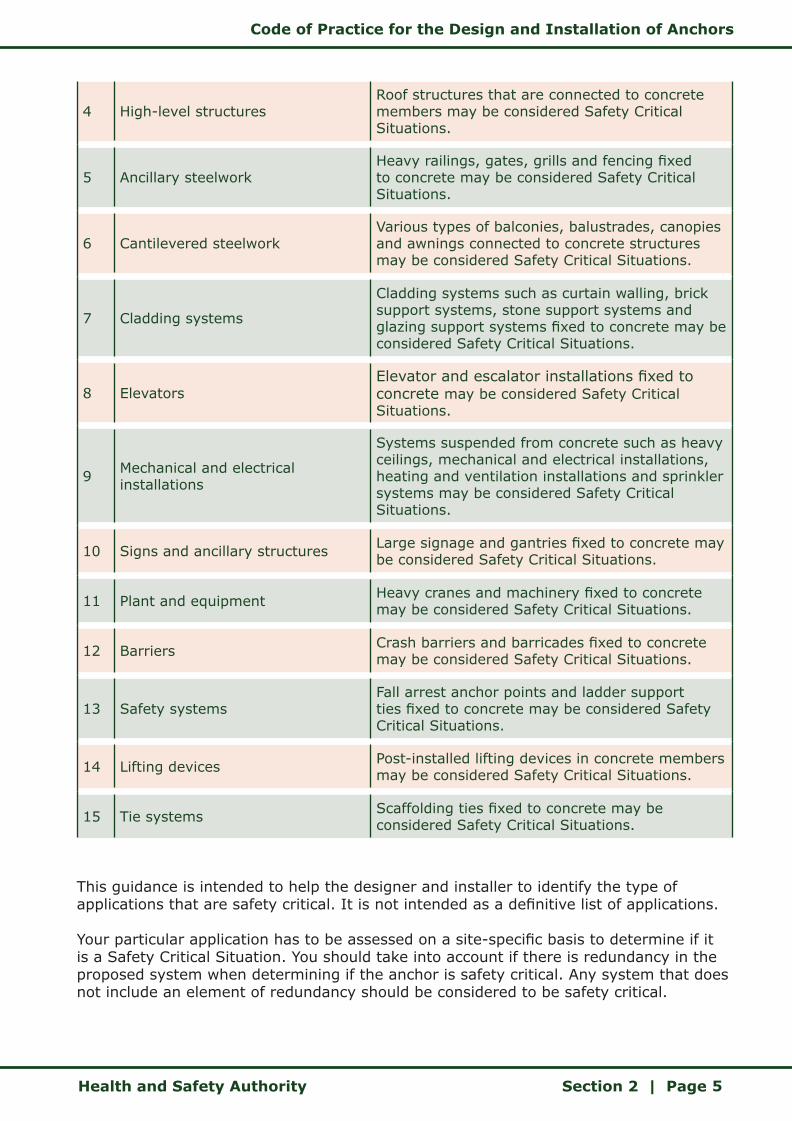
Owing to the vast range of applications for anchors it is impossible to create a complete list of cases where anchorages would be considered to be safety critical. This code of practice therefore provides guidance and examples of cases where anchorages could be safety critical. The designer must always complete a design risk assessment in order to verify if the application is a Safety Critical Situation.
Table 2.1: Examples of Safety Critical Situations
1 Structural connection in concrete
The use of chemical resin to provide post-installed reinforcement bars in a concrete structure may be a Safety Critical Situation if the bars are subjected to high-tensile loads.
2 Structural steel connectionsThe connection of structural steel beams or columns to concrete members may be considered Safety Critical Situations.
3 Temporary works
In concrete structures many forms of shuttering, formwork, temporary propping and temporary supports fixed to concrete may be considered Safety Critical Situations.
Code of Practice for the Design and Installation of Anchors
Health and Safety Authority Section 2 | Page 5
4 High-level structures Roof structures that are connected to concrete members may be considered Safety Critical Situations.
5 Ancillary steelwork Heavy railings, gates, grills and fencing fixed to concrete may be considered Safety Critical Situations.
6 Cantilevered steelwork Various types of balconies, balustrades, canopies and awnings connected to concrete structures may be considered Safety Critical Situations.
7 Cladding systems
Cladding systems such as curtain walling, brick support systems, stone support systems and glazing support systems fixed to concrete may be considered Safety Critical Situations.
8 Elevators Elevator and escalator installations fixed to concrete may be considered Safety Critical Situations.
9 Mechanical and electrical installations
Systems suspended from concrete such as heavy ceilings, mechanical and electrical installations, heating and ventilation installations and sprinkler systems may be considered Safety Critical Situations.
10 Signs and ancillary structures Large signage and gantries fixed to concrete may be considered Safety Critical Situations.
11 Plant and equipment Heavy cranes and machinery fixed to concrete may be considered Safety Critical Situations.
12 Barriers Crash barriers and barricades fixed to concrete may be considered Safety Critical Situations.
13 Safety systems Fall arrest anchor points and ladder support ties fixed to concrete may be considered Safety Critical Situations.
14 Lifting devices Post-installed lifting devices in concrete members may be considered Safety Critical Situations.
15 Tie systems Scaffolding ties fixed to concrete may be considered Safety Critical Situations.
This guidance is intended to help the designer and installer to identify the type of applications that are safety critical. It is not intended as a definitive list of applications.
Your particular application has to be assessed on a site-specific basis to determine if it is a Safety Critical Situation. You should take into account if there is redundancy in the proposed system when determining if the anchor is safety critical. Any system that does not include an element of redundancy should be considered to be safety critical.

Code of Practice for the Design and Installation of Anchors
Section 2 | Page Health and Safety Authority6
The examples given in Table 2.1 demonstrate the range of applications in which anchors are used. While there may be hundreds of anchors used in a particular application, there is often a single design taking the worst-case loading. This design is then applied to all instances of that application on the project.
The following panels set out the role of the designer, the anchor supplier and the anchor installer when fixing mechanical plant to the underside of a concrete slab. In this example the equipment will be suspended from the slab within a service void that is above a corridor in a building.
Designer
• Decides an anchor is required.• Completes a design risk assessment to determine if it is a Safety Critical
Situation.• Gathers all necessary information to design the anchor, using form FM-01
(Appendix A) or a drawing to communicate the requirements. • If the anchor manufacturer/supplier is assisting in the design, the designer
must approve the design. • If designing the anchor, completes form FM-02 (Appendix A).
Anchor Manufacturer/Supplier
• Provides information on available/suitable anchors. • Assists in the design of the anchor if requested and if competent to
undertake the design. • Advises on alternative anchors. • If designing the anchor, completes form FM-02 (Appendix A) and sends
this or a computer printout to the designer for approval.
The following panels set out the role of the designer, the anchor supplier and the anchor installer when fixing mechanical plant to the underside of a concrete slab. In this example the equipment will be suspended from the slab within a service void that is above a corridor in a building.

Code of Practice for the Design and Installation of Anchors
Health and Safety Authority Section 2 | Page 7
Sample forms are provided in Appendix A, which may be used communicating the specification and correct installation of the anchor. They are not mandatory forms and anchor specifiers and installers may use their own versions.
The first form (Anchor/FM-01) helps the designer to gather the information that is necessary to complete the anchor design. Alternatively the information can be communicated by including the anchor requirements on drawings.
The second form (Anchor/FM-02) communicates the anchor specification to the contractor. Alternatively the information can be communicated using the anchor manufacturer’s computer printout or hand calculations.
For each application there will generally be one anchor design, which will specify the anchor that is to be used on site. Even though there may be several hundred of these anchors installed, there is one design and therefore one design form to be completed by the anchor specifier.
The third form (Anchor/FM-03) is used as a checklist by the contractor supervising the installation of the anchor on site.
European Technical Approval (ETA)
Currently there are only ETAs for structural connections in concrete. Therefore it is generally not acceptable to design, specify or install anchors for use in a Safety Critical Situation that do not have an ETA or that are to be installed in any base material other than concrete. This is primarily due to the current lack of reliable load data for anchors in base materials such as masonry or brickwork, without site-specific testing.
In the event that it is not practicable to install an anchor in concrete, the anchor specifier may specify the use of an anchor in a base material other than concrete. In such cases the anchor specifier must satisfy himself or herself that the capacity of the connection (anchor and base material) specified is sufficient to support the design loads adequately. The anchor manufacturer must be consulted on the use of the anchor outside of its ETA. The capacity of the specified connection must be fully assessed and agreed as being adequate between the anchor specifier and the anchor manufacturer.
Anchor technology is continually evolving and new solutions are being developed for
Anchor Installer
• Purchases the correct anchor. • Installs the anchor in accordance with the manufacturer’s instructions. • If there are installation problems on site, then discusses these with the
contractor and anchor designer. • Supervises installation and completes form FM-03 (Appendix A).
Code of Practice for the Design and Installation of Anchors
Section 2 | Page Health and Safety Authority8
masonry. Once these anchors have received an ETA they will be available to anchor specifiers to design for use in masonry, in accordance with the design method in the Guideline for European Technical Approval (ETAG).
The design of the connection must be clearly and unambiguously communicated to the anchor installer. This is a particular requirement where the connection design deviates from its ETA.
The design of the anchor is a critical element in the integrity of the structure and contributes to its stability and robustness. Accordingly, verifiable calculations and drawings are to be prepared by the anchor specifier, taking account of all the loads and load paths acting on the anchor.
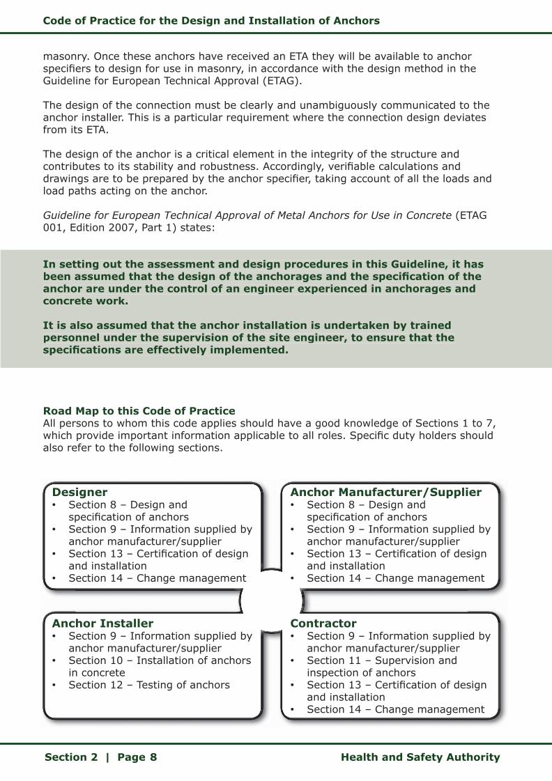
Guideline for European Technical Approval of Metal Anchors for Use in Concrete (ETAG 001, Edition 2007, Part 1) states:
In setting out the assessment and design procedures in this Guideline, it has been assumed that the design of the anchorages and the specification of the anchor are under the control of an engineer experienced in anchorages and concrete work.
It is also assumed that the anchor installation is undertaken by trained personnel under the supervision of the site engineer, to ensure that the specifications are effectively implemented.
Road Map to this Code of Practice All persons to whom this code applies should have a good knowledge of Sections 1 to 7, which provide important information applicable to all roles. Specific duty holders should also refer to the following sections.
In setting out the assessment and design procedures in this Guideline, it has been assumed that the design of the anchorages and the specification of the anchor are under the control of an engineer experienced in anchorages and concrete work.
It is also assumed that the anchor installation is undertaken by trained personnel under the supervision of the site engineer, to ensure that the specifications are effectively implemented.
Designer • Section 8 – Design and
specification of anchors• Section 9 – Information supplied by
anchor manufacturer/supplier• Section 13 – Certification of design
and installation• Section 14 – Change management
Anchor Manufacturer/Supplier• Section 8 – Design and
specification of anchors• Section 9 – Information supplied by
anchor manufacturer/supplier• Section 13 – Certification of design
and installation• Section 14 – Change management
Anchor Installer • Section 9 – Information supplied by
anchor manufacturer/supplier• Section 10 – Installation of anchors
in concrete• Section 12 – Testing of anchors
Contractor • Section 9 – Information supplied by
anchor manufacturer/supplier• Section 11 – Supervision and
inspection of anchors • Section 13 – Certification of design
and installation• Section 14 – Change management
Code of Practice for the Design and Installation of Anchors
Health and Safety Authority Section 3 | Page 9
3 INTRODUCTION
Anchors play an important role in construction:
z They allow for the speedy connection of two or more structural elements.
z Anchors with ETA are manufactured to a high standard and are only awarded an ETA after rigorous testing.
z There is a wide variety of anchors available for different applications.
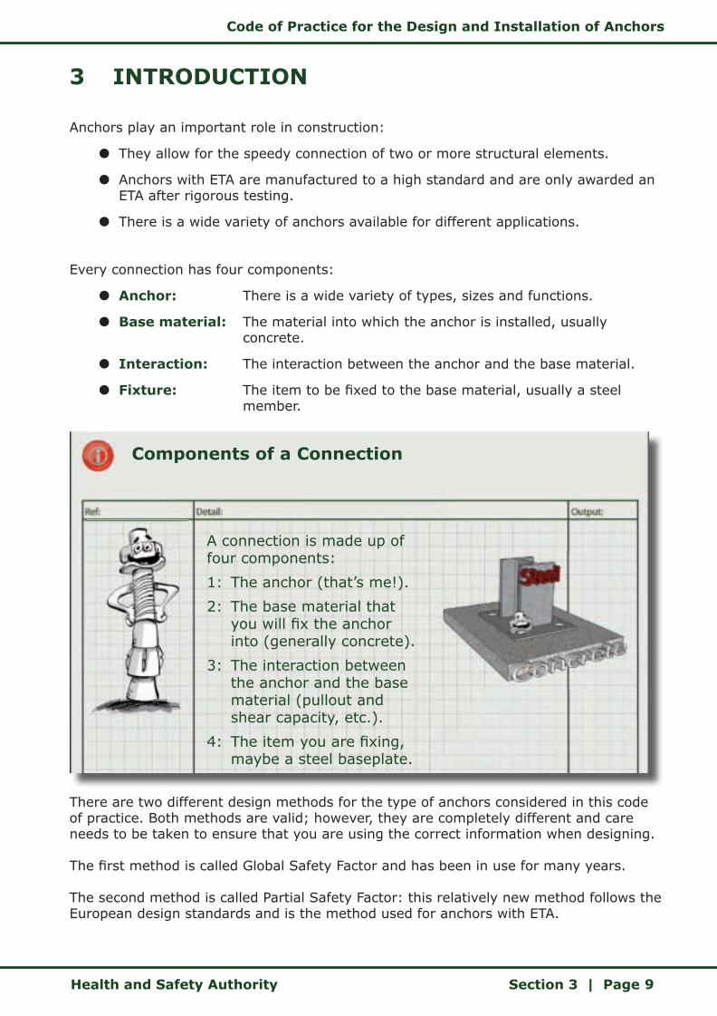
Every connection has four components:
z Anchor: There is a wide variety of types, sizes and functions.
z Base material: The material into which the anchor is installed, usually concrete.
z Interaction: The interaction between the anchor and the base material.
z Fixture: The item to be fixed to the base material, usually a steel member.
Components of a Connection
A connection is made up of four components:
1: The anchor (that’s me!).
2: The base material that you will fix the anchor into (generally concrete).
3: The interaction between the anchor and the base material (pullout and shear capacity, etc.).
4: The item you are fixing, maybe a steel baseplate.
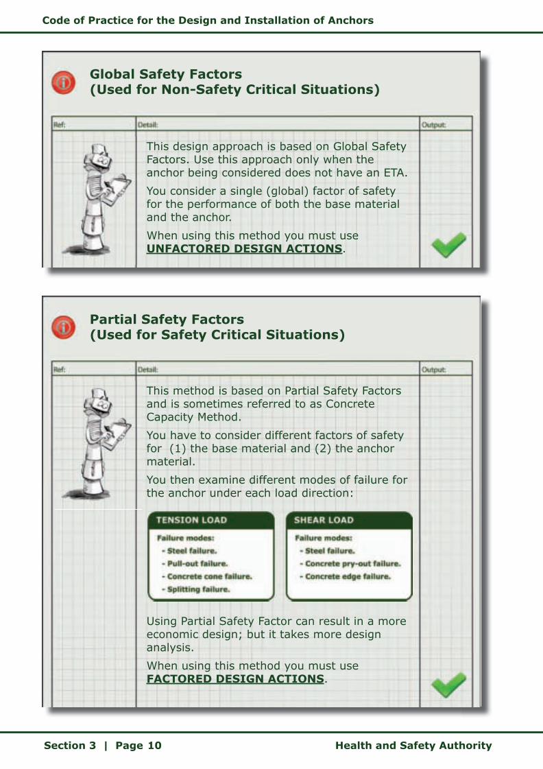
There are two different design methods for the type of anchors considered in this code of practice. Both methods are valid; however, they are completely different and care needs to be taken to ensure that you are using the correct information when designing.
The first method is called Global Safety Factor and has been in use for many years.
The second method is called Partial Safety Factor: this relatively new method follows the European design standards and is the method used for anchors with ETA.
Code of Practice for the Design and Installation of Anchors
Section 3 | Page Health and Safety Authority10
Global Safety Factors (Used for Non-Safety Critical Situations)
This design approach is based on Global Safety Factors. Use this approach only when the anchor being considered does not have an ETA.
You consider a single (global) factor of safety for the performance of both the base material and the anchor.
When using this method you must use UNFACTORED DESIGN ACTIONS.
Partial Safety Factors (Used for Safety Critical Situations)
This method is based on Partial Safety Factors and is sometimes referred to as Concrete Capacity Method.
You have to consider different factors of safety for (1) the base material and (2) the anchor material.
You then examine different modes of failure for the anchor under each load direction:
Using Partial Safety Factor can result in a more economic design; but it takes more design analysis.
When using this method you must use FACTORED DESIGN ACTIONS.

Code of Practice for the Design and Installation of Anchors
Health and Safety Authority Section 3 | Page 11
Irrespective of the design method used, all anchor specifiers need to ensure that they have up-to-date technical data from the anchor supplier for the particular anchor being considered.
The anchor specifier needs to establish which design method is most appropriate for the connection. During the design process the anchor specifier must strictly comply with the chosen design method, in particular by using the capacities stated in the ETA for both the chosen anchor and the design method.
For example:
z If the anchor specifier is using a Global Safety Factor design approach, Un-factored Design Actions must be compared to the Recommended Loads stated in the technical manual for the particular anchor.
z If the anchor specifier is using a Partial Safety Factor design approach, the Factored Design Actions must be compared to the Design Resistance for the particular anchor.
z Anchor manufacturers often give technical data relating to the ultimate resistance or characteristic resistance of the anchor. This information must not be used in any anchor design, irrespective of the design method chosen.
The anchor specifier needs to consider all loads that will act on an anchor and the direction of these loads. Loads will change during the construction process and the anchor specifier needs to ensure that the most onerous load conditions have been considered.
Once the chosen design method has been fully completed, the anchor specifier needs to conclude the design process by specifying the anchor. The anchor specifier must detail the anchor explicitly, so that the correct anchor is procured and installed. To achieve this, the anchor specifier should use the full anchor designation that is in the anchor manufacturer’s technical manual.
At this stage the anchor can be installed by the contractor on site. The contractor must ensure that the anchor installer has the most up-to-date information for the installation of the anchor. Different types of anchor have specific requirements for the correct installation. If these are not followed, as per the manufacturer’s instructions, then the anchor may not have the capacity determined by the anchor specifier. Common errors that can occur on site include:
z Use of a drill bit with the wrong diameter.
z Use of a wrong drilling system, for example in case of undercut anchors.
z Use of wrong setting tools, for example not using a torque wrench for torque controlled expansion anchors.
z Failure to clean the hole, if cleaning is required by the manufacturer.
z Installation of the anchor such that the fixture cannot be installed without significant manipulations, for example anchor is not flush with the concrete surface in cases where required.
z Hammering in an anchor that should be installed by rotation, for example anchor rod for a bonded anchor.
Each of these errors could seriously affect the performance and capacity of the installed
Code of Practice for the Design and Installation of Anchors
Section 3 | Page Health and Safety Authority12
anchor. Table 7.1 details information that the anchor specifier should provide to the anchor installer in order to prevent these errors occurring on site (see Section 7).
The anchor supplier should make technical information available to both the anchor specifier and the anchor installer to allow them to undertake their tasks. Specifiers and installers should consult with the anchor manufacturer if there is any doubt as to the choice of the appropriate anchor or the correct installation procedures.
Code of Practice for the Design and Installation of Anchors
Health and Safety Authority Section 4 | Page 13
4 DEFINITIONS
The following definitions relate to this code of practice.
“Admissible loading” means the load allowed for a fastener under service conditions as per a design code. For anchors designed in accordance with the Concrete Capacity Method, loads are factored by the appropriate factor of safety. The loading can be applied in different directions:
z Axial (tension or compression): Load application in the direction of the axis of the anchor.
z Shear: Direction of load application is perpendicular to the axis of the anchor.
z Combined tension and shear: Combination of tensile and shear loading applied simultaneously.
z Bending: Shear with lever arm applied to an anchor (e.g. a stand-off detail).
“Anchor” means a manufactured, assembled component for achieving a connection between the base material and the fixture. Under the Safety, Health and Welfare at Work Act 2005, an anchor is considered to be an article. There are currently four main types of anchor:
z Torque-controlled expansion anchors.
z Undercut anchors.
z Deformation-controlled expansion anchors.
z Bonded anchors.
“Anchor installer” means a competent person or organisation who installs anchors.
“Anchor manufacturer/supplier” means a competent person or organisation who designs, manufactures, imports or supplies anchors. An anchor manufacturer could also be an anchor specifier.
“Anchor specifier” means a competent person or organisation who designs the connection and specifies an anchor.
“Article” means:
z Any plant, machine, machinery, appliance, apparatus, tool or any other work equipment for use or operation (whether exclusively or not) by persons at work.
z Any article designed for use as a component in, part of or to control any such plant, machine, machinery, appliance, apparatus, work equipment, tool or any other work equipment.
z Any other product used by persons at work.
Code of Practice for the Design and Installation of Anchors
Section 4 | Page Health and Safety Authority14
“Base material” means the material into which the anchor is installed. In the context of this code of practice the only base material currently considered is concrete. The concrete may be cracked (in the tensile zone of the concrete member) or non-cracked (in the compression zone of the concrete member).
“Client” means any person engaged in trade, business or other undertaking who commissions or procures the carrying out of a project or who undertakes a project directly for the purpose of such trade, business or undertaking.
“Competent person” means a person who, having regard to the task he or she is required to perform and taking account of the size or hazards (or both of them) of the undertaking or establishment in which he or she undertakes work, the person possesses sufficient training, experience and knowledge appropriate to the nature of the work to be undertaken.
“Concrete Capacity Method” means the Partial Safety Factor design method for connections under due consideration of the safety and design concept within the scope of the European Technical Approvals of anchors.
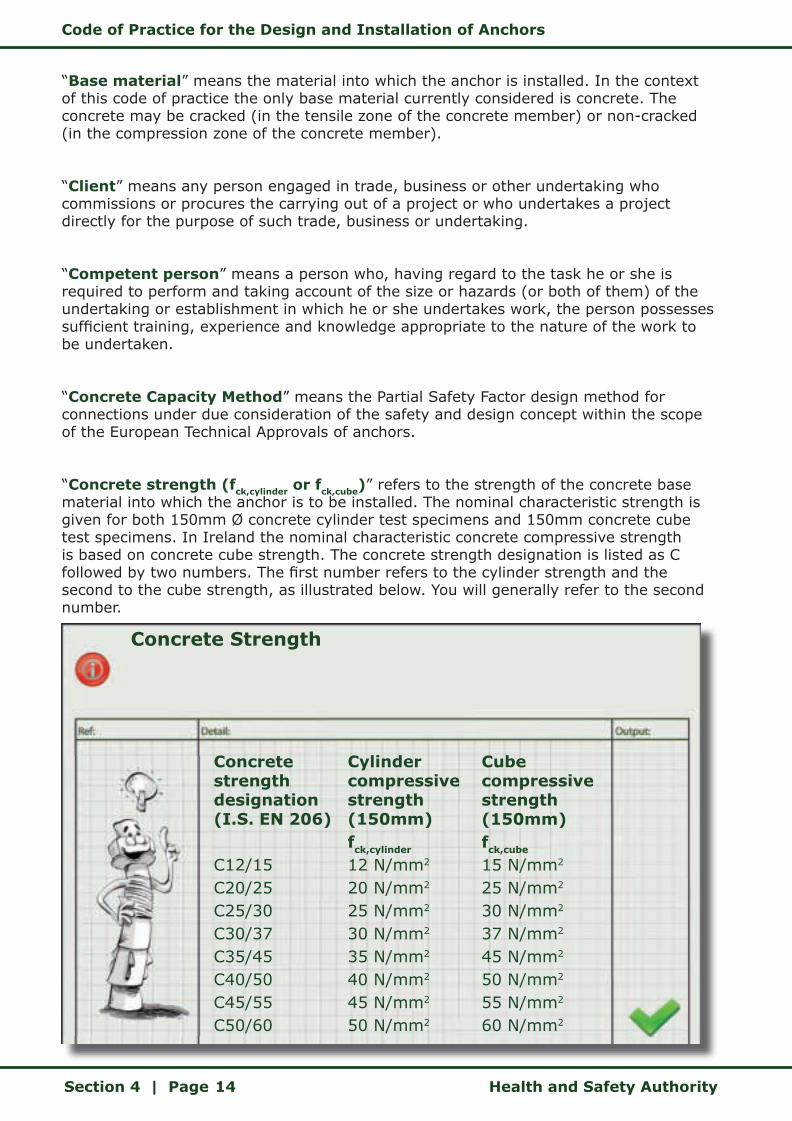
“Concrete strength (fck,cylinder or fck,cube)” refers to the strength of the concrete base material into which the anchor is to be installed. The nominal characteristic strength is given for both 150mm Ø concrete cylinder test specimens and 150mm concrete cube test specimens. In Ireland the nominal characteristic concrete compressive strength is based on concrete cube strength. The concrete strength designation is listed as C followed by two numbers. The first number refers to the cylinder strength and the second to the cube strength, as illustrated below. You will generally refer to the second number.
Concrete Strength
Concrete strength designation (I.S. EN 206)
C12/15C20/25C25/30C30/37C35/45C40/50C45/55C50/60
Cylinder compressive strength (150mm)fck,cylinder 12 N/mm2
20 N/mm2
25 N/mm2
30 N/mm2
35 N/mm2
40 N/mm2
45 N/mm2
50 N/mm2
Cube compressive strength (150mm)fck,cube 15 N/mm2
25 N/mm2
30 N/mm2
37 N/mm2
45 N/mm2
50 N/mm2
55 N/mm2
60 N/mm2
Code of Practice for the Design and Installation of Anchors
Health and Safety Authority Section 4 | Page 15
“Connection” means an assembly comprising the base material (concrete), the anchor or anchor group and the component/fixture fixed to the concrete.
“Contractor” means a competent contractor or an employer whose employees undertake, carry out or manage construction work, or any person who carries out or manages construction work for a fixed or other sum and who supplies the materials and labour (whether his or her own labour or that of another) to carry out such work or who supplies the labour only.
“Construction Products Directive (CPD)” is the European Council Directive 89/106/EC relating to construction products. The six essential requirements are:
z Mechanical resistance and stability.
z Safety in case of fire.
z Hygiene, health and the environment.
z Safety in use.
z Protection against noise.
z Energy economy and heat retention.
“Construction stage” means the period of time that starts when preparation of the construction site begins and ends when construction work on the project is complete.
“Creep” means the condition whereby some materials may sustain a particular level of stress over the short term but will fail at significantly lower levels over the long term. This condition afflicts plastic and some resin materials and, to put it into context, to a small degree concrete. All anchors with ETAs have satisfied sustained load tests and are suitable for long-term loadings, they will not exhibit the characteristics of creep when subject to the design resistances implicit in the ETA.
“Design” means the preparation of drawings, particulars, specifications, calculations, the preambles and preliminaries of bills of quantities in so far as they contain specifications or other expressions of purpose, according to which a project, or any part or component of a project, is to be executed.
“Design action” means the force acting on the anchor. This code considers three basic design actions:
z Tension.
z Shear.
z Combined shear and tension (or bending).
“Design process” means the process for preparing and designing a project, including alterations to the design and the design of temporary works to facilitate construction of the project.
Code of Practice for the Design and Installation of Anchors
Section 4 | Page Health and Safety Authority16
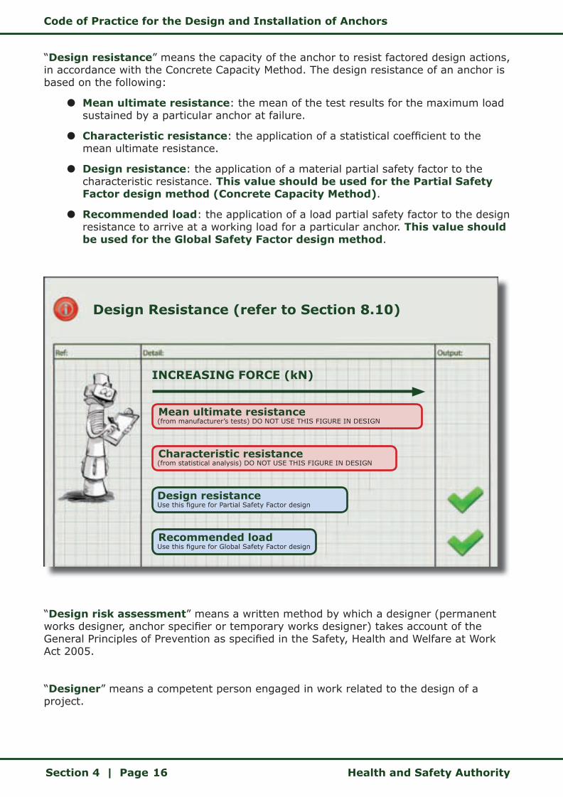
“Design resistance” means the capacity of the anchor to resist factored design actions, in accordance with the Concrete Capacity Method. The design resistance of an anchor is based on the following:
z Mean ultimate resistance: the mean of the test results for the maximum load sustained by a particular anchor at failure.
z Characteristic resistance: the application of a statistical coefficient to the mean ultimate resistance.
z Design resistance: the application of a material partial safety factor to the characteristic resistance. This value should be used for the Partial Safety Factor design method (Concrete Capacity Method).
z Recommended load: the application of a load partial safety factor to the design resistance to arrive at a working load for a particular anchor. This value should be used for the Global Safety Factor design method.
“Design risk assessment” means a written method by which a designer (permanent works designer, anchor specifier or temporary works designer) takes account of the General Principles of Prevention as specified in the Safety, Health and Welfare at Work Act 2005.
“Designer” means a competent person engaged in work related to the design of a project.
Design Resistance (refer to Section 8.10)
INCREASING FORCE (kN)
Mean ultimate resistance (from manufacturer’s tests) DO NOT USE THIS FIGURE IN DESIGN
Characteristic resistance (from statistical analysis) DO NOT USE THIS FIGURE IN DESIGN
Design resistance Use this figure for Partial Safety Factor design
Recommended load Use this figure for Global Safety Factor design
Code of Practice for the Design and Installation of Anchors
Health and Safety Authority Section 4 | Page 17
“Elongation” means the movement of the anchor under load contributed by the strain of the steel and elastic concrete strain (excluding slip of the anchor).
“EOTA” is the European Organisation for Technical Approvals. The role of EOTA is primarily to monitor and progress the drafting of Guidelines for European Technical Approvals (ETAGs) and to coordinate all activities relating to the issuing of European Technical Approvals (ETAs). EOTA operates in close co-operation with the European Commission, European Free Trade Association (EFTA), European Committee for Standardisation (CEN), European trade associations and industrial organisations, which are also present as observers at various EOTA levels. EOTA is born out of the Construction Products Directive 89/106/EC (CPD). EOTA comprises the Approval Bodies nominated to issue European Technical Approvals (ETAs) by EU Member States and EFTA States who have contracted to the European Economic Area Agreement.
“ETA” means a European Technical Approval. An ETA for a construction product is a favourable technical assessment of its fitness for an intended use, based on the contribution made by this product to the fulfillment of the six essential requirements stated in the CPD for the construction works in which the product is installed. An anchor with a current ETA has CE Marking status.
“Fixture” means a component to be fixed to the concrete base material.
“Global safety factor” means the application of a single safety factor (n) to the mean ultimate failure of the anchor. This determines the recommended load.
“Partial safety factor” means the strict separation of factors of safety for both the anchor materials and the applied loads, as detailed below.
z Partial safety factor for the applied loads, represented by the symbol gF.
z Partial safety factor for material failure modes, represented by the symbol gM. Depending on the failure mode there are four partial safety factors that you need to consider:
z gMs for steel failure.
z gMp for pull-out failure.
z gMc for concrete cone failure.
z gMsp for splitting failure.
Partial safety factors are applicable to the Concrete Capacity Method.
“Permanent works designer” means a competent person engaged in the design of the permanent structure. A permanent works designer could be an anchor specifier.
Code of Practice for the Design and Installation of Anchors
Section 4 | Page Health and Safety Authority18
“Project supervisor construction stage (PSCS)” means a competent person appointed by the client under the Safety, Health and Welfare at Work (Construction) Regulations 2006 to carry out the duties under Regulations 16 to 22.
“Project supervisor design process (PSDP)” means a competent person appointed by the Client under the Safety, Health and Welfare at Work (Construction) Regulations 2006 to carry out the duties under Regulations 11 to 14.
“Safety Critical Situation” means circumstances where the failure of such connections would cause risk of human injury or death.
“Temporary works” means any temporary structure used to support a permanent structure while it is not self-supporting.
“Temporary works designer” means a competent person engaged in the design of temporary works. A temporary works designer could be an anchor specifier.
“Temporary works erector” means a competent person whose employees undertake, carry out or manage the erection of temporary works, or any person who carries out or manages the erection of temporary works for a fixed or other sum and who supplies the materials and labour (whether his or her own labour or that of another) to carry out such work or who supplies the labour only.
Code of Practice for the Design and Installation of Anchors
Health and Safety Authority Section 5 | Page 19
5 BACKGROUND TO THE CONSTRUCTION PRODUCTS DIRECTIVE
The basic legal European Union document for building products is the Construction Products Directive (89/106/EEC) or CPD, which has to be translated into national law by all Member States. The CPD indicates the procedure for the verification of building products so that they are suitable for their intended application. The Directive applies to construction products used in buildings and on civil engineering projects. Construction products that fall within the scope of the CPD, have to meet specific requirements under the six essential requirements that apply to all building products:
z Mechanical resistance and stability.
z Safety in case of fire.
z Hygiene, health and the environment.
z Safety in use.
z Protection against noise.
z Energy economy and heat retention.
For each construction product family, a specific Guideline for European Technical Approval (ETAG) is required in which particular characteristics are given. The ETAG describes the necessary tests and defines the requirements. For example, ETAG 001, Part 1, Edition 2007: Guideline for European Technical Approval of Metal Anchors for Use in Concrete. Based on this guideline, a European Technical Approval (ETA) can be granted by an approved body for each construction product, in this case metal anchors for use in concrete. There are numerous other European Commission documents that give assistance with particular problems, for example attestation of conformity, CE marking or quality assurance.
The CPD is largely aimed at governments, i.e. the legislators of the Member States. The six essential requirements are directed at specialists for the preparation of guidelines and standards in particular. The ETAG regulates the tasks and obligations of:
z The approval bodies in the member countries (e.g. IAB, DIBt, CSTB, BBA).
z The approved bodies (independent test laboratories and institutions for quality assurance).
z The anchor manufacturer.
The anchor specifier is directed to ETAG 001, Annex C: Design methods for anchorages. Together with the Concrete Capacity Method specified in Annex C and the data for a specific anchor from its ETA, the specifier is required to design the connection for the selected anchor in the conditions in which it will be used.
The ETA for a particular anchor is an important design document, as it provides the anchor specifier with:
z Confirmation that an anchor has undergone stringent testing to one or more

Code of Practice for the Design and Installation of Anchors
Section 5 | Page Health and Safety Authority20
of the twelve design options and will therefore function reliably and that its performance can be compared with that of others on a like for like basis.
z Clear direction as to the intended use of the anchor.
z The characteristics of the anchor – sizes, tolerances, material values, markings etc.
z Details of the anchor manufacturer’s factory production controls.
z Requirements for CE Marking.
z Technical data for the different anchor-sizes covered by the ETA.
z Installation details, for example minimum depth of embedment, hole diameter and setting tools.
z The characteristic resistance of the anchor for tension and shear, as determined by laboratory testing.
z The relevant partial safety factors.
z Requirements for minimum thickness of base material.
z Requirements for anchor spacing and edge distances.
The 1989 CPD has been addressed in Ireland by the European Communities (Construction Products) Regulations 1992 (S.I. No. 198 of 1992) and the European
Important Design Note
The Characteristic Resistance of the anchor in the manufacturer’s technical data should not be used for design purposes, unless the appropriate partial safety factor has been applied.
Each manufacturer provides Design Resistance values for their ETA anchors, which allow the anchor specifier to use the Partial Safety Factor design approach in accordance with Annex C of ETAG 001.
When using a Global Safety Factor design approach use the Recommended Loads given by the manufacturer.
Code of Practice for the Design and Installation of Anchors
Health and Safety Authority Section 5 | Page 21
Communities (Construction Products)(Amendment) Regulations 1994 (S.I. No. 210 of 1994).
There is a link between the proposed ETAs and the CPD. In particular the use of anchors in accordance with the ETA provides a means for building and civil engineering works to comply with the six essential requirements of this Council Directive.
In the context of safety in the design and installation of anchors, essential requirements 1 (mechanical resistance and stability), 2 (safety in case of fire) and 4 (safety in use) are of particular importance.
1 Mechanical resistance and stability The construction works must be designed and built in such a way that the loadings that are liable to act on it during its construction and use will not lead to:
z Collapse of the whole or part of the work.
z Major deformations to an inadmissible degree.
z Damage to other parts of the works or to fittings or installed equipment as a result of major deformation of the load-bearing construction.
z Damage by an event to an extent disproportionate to the original cause.
2 Safety in case of fireThe construction works must be designed and built in such a way that in the event of an outbreak of fire:
z The load-bearing capacity of the construction can be assumed for a specific period of time.
z The generation and spread of fire and smoke within the whole works are limited.
z The spread of the fire to neighbouring construction works is limited.
z Occupants can leave the works or be rescued by other means.
z The safety of rescue teams is taken into consideration.
3 Hygiene, health and the environmentThe construction works must be designed and built in such a way that it will not be a threat to the hygiene or health of the occupants or neighbours, in particular as a result of:
z Giving off of toxic gas.
z Presence of dangerous particles or gases in the air.
z Emission of dangerous radiation.
z Pollution or poisoning of the water or soil.

Code of Practice for the Design and Installation of Anchors
Section 5 | Page Health and Safety Authority22
z Faulty elimination of waste water, smoke, solid or liquid wastes.
z Presence of damp in parts of the works or on surfaces within the works.
4 Safety in useThe construction work must be designed and built in such a way that it does not present unacceptable risks of accidents in service or in operation such as slipping, falling, collision, burns, electrocution and injury from explosion.
5 Protection against noiseThe construction works must be designed and built in such a way that noise perceived by the occupants or people nearby is kept down to a level that will not threaten their health and will allow them to sleep, rest and work in satisfactory conditions.
6 Energy economy and heat retentionThe construction works and its heating, cooling and ventilation installations must be designed and built in such a way that the amount of energy required in use shall be low, having regard to the climatic conditions of the location and the occupants.
Code of Practice for the Design and Installation of Anchors
Health and Safety Authority Section 6 | Page 23
6 TYPES OF ANCHORS COVERED BY THIS CODE OF PRACTICE
There are currently four anchor types covered by ETAG 001 for which it is possible to get an ETA.
Each part of ETAG 001 deals with an individual type of anchor, as set out below.
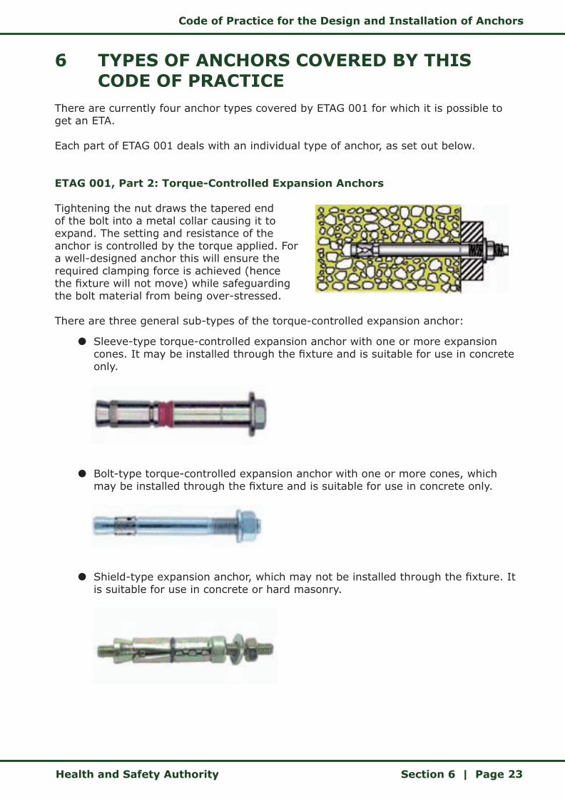
ETAG 001, Part 2: Torque-Controlled Expansion Anchors
Tightening the nut draws the tapered end of the bolt into a metal collar causing it to expand. The setting and resistance of the anchor is controlled by the torque applied. For a well-designed anchor this will ensure the required clamping force is achieved (hence the fixture will not move) while safeguarding the bolt material from being over-stressed.
There are three general sub-types of the torque-controlled expansion anchor:
z Sleeve-type torque-controlled expansion anchor with one or more expansion cones. It may be installed through the fixture and is suitable for use in concrete only.
z Bolt-type torque-controlled expansion anchor with one or more cones, which may be installed through the fixture and is suitable for use in concrete only.
z Shield-type expansion anchor, which may not be installed through the fixture. It is suitable for use in concrete or hard masonry.
Code of Practice for the Design and Installation of Anchors
Section 6 | Page Health and Safety Authority24
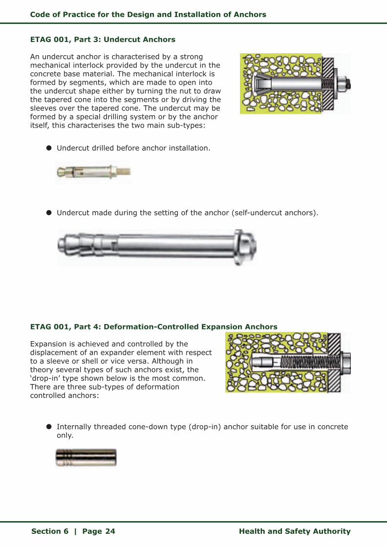
ETAG 001, Part 3: Undercut Anchors
An undercut anchor is characterised by a strong mechanical interlock provided by the undercut in the concrete base material. The mechanical interlock is formed by segments, which are made to open into the undercut shape either by turning the nut to draw the tapered cone into the segments or by driving the sleeves over the tapered cone. The undercut may be formed by a special drilling system or by the anchor itself, this characterises the two main sub-types:
z Undercut drilled before anchor installation.
z Undercut made during the setting of the anchor (self-undercut anchors).
ETAG 001, Part 4: Deformation-Controlled Expansion Anchors
Expansion is achieved and controlled by the displacement of an expander element with respect to a sleeve or shell or vice versa. Although in theory several types of such anchors exist, the ‘drop-in’ type shown below is the most common. There are three sub-types of deformation controlled anchors:
z Internally threaded cone-down type (drop-in) anchor suitable for use in concrete only.

Code of Practice for the Design and Installation of Anchors
Health and Safety Authority Section 6 | Page 25
z Shank-down type anchor (stud anchor).
z Sleeve-down type anchor.
ETAG 001, Part 5: Bonded Anchors
The anchor is bonded to the base material by either a two-part resin grout or a cementitious grout, which may be introduced either in a capsule or from an injection cartridge with special mixing nozzle. These anchors are based on a wide variety of mixing techniques and installation procedures. The sub-types based on installation techniques include:
z Bonded anchor.
z Undercut bonded anchor.
z Torque-controlled bonded anchor.
There are sub-types, which are also based on the different techniques for mixing the bonding agent and include:
z Glass or soft skin capsule.
z Injection type.
Code of Practice for the Design and Installation of Anchors
Section 6 | Page Health and Safety Authority26
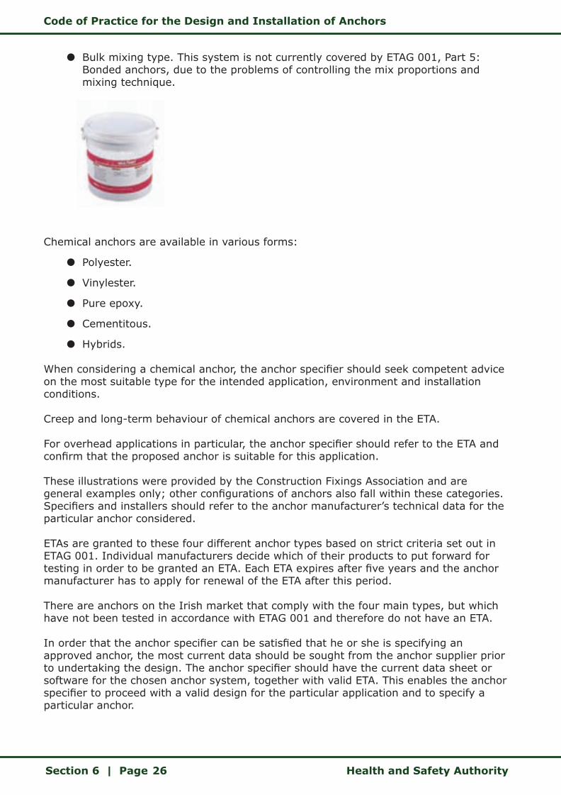
z Bulk mixing type. This system is not currently covered by ETAG 001, Part 5: Bonded anchors, due to the problems of controlling the mix proportions and mixing technique.
Chemical anchors are available in various forms:
z Polyester.
z Vinylester.
z Pure epoxy.
z Cementitous.
z Hybrids.
When considering a chemical anchor, the anchor specifier should seek competent advice on the most suitable type for the intended application, environment and installation conditions.
Creep and long-term behaviour of chemical anchors are covered in the ETA.
For overhead applications in particular, the anchor specifier should refer to the ETA and confirm that the proposed anchor is suitable for this application.
These illustrations were provided by the Construction Fixings Association and are general examples only; other configurations of anchors also fall within these categories. Specifiers and installers should refer to the anchor manufacturer’s technical data for the particular anchor considered.
ETAs are granted to these four different anchor types based on strict criteria set out in ETAG 001. Individual manufacturers decide which of their products to put forward for testing in order to be granted an ETA. Each ETA expires after five years and the anchor manufacturer has to apply for renewal of the ETA after this period.
There are anchors on the Irish market that comply with the four main types, but which have not been tested in accordance with ETAG 001 and therefore do not have an ETA.
In order that the anchor specifier can be satisfied that he or she is specifying an approved anchor, the most current data should be sought from the anchor supplier prior to undertaking the design. The anchor specifier should have the current data sheet or software for the chosen anchor system, together with valid ETA. This enables the anchor specifier to proceed with a valid design for the particular application and to specify a particular anchor.
Code of Practice for the Design and Installation of Anchors
Health and Safety Authority Section 6 | Page 27
Similarly the anchor installer needs to be satisfied that the anchor provided complies with the design and that the anchor has an ETA. This can be confirmed by the presence of the CE Mark and the ETA number on the packaging.
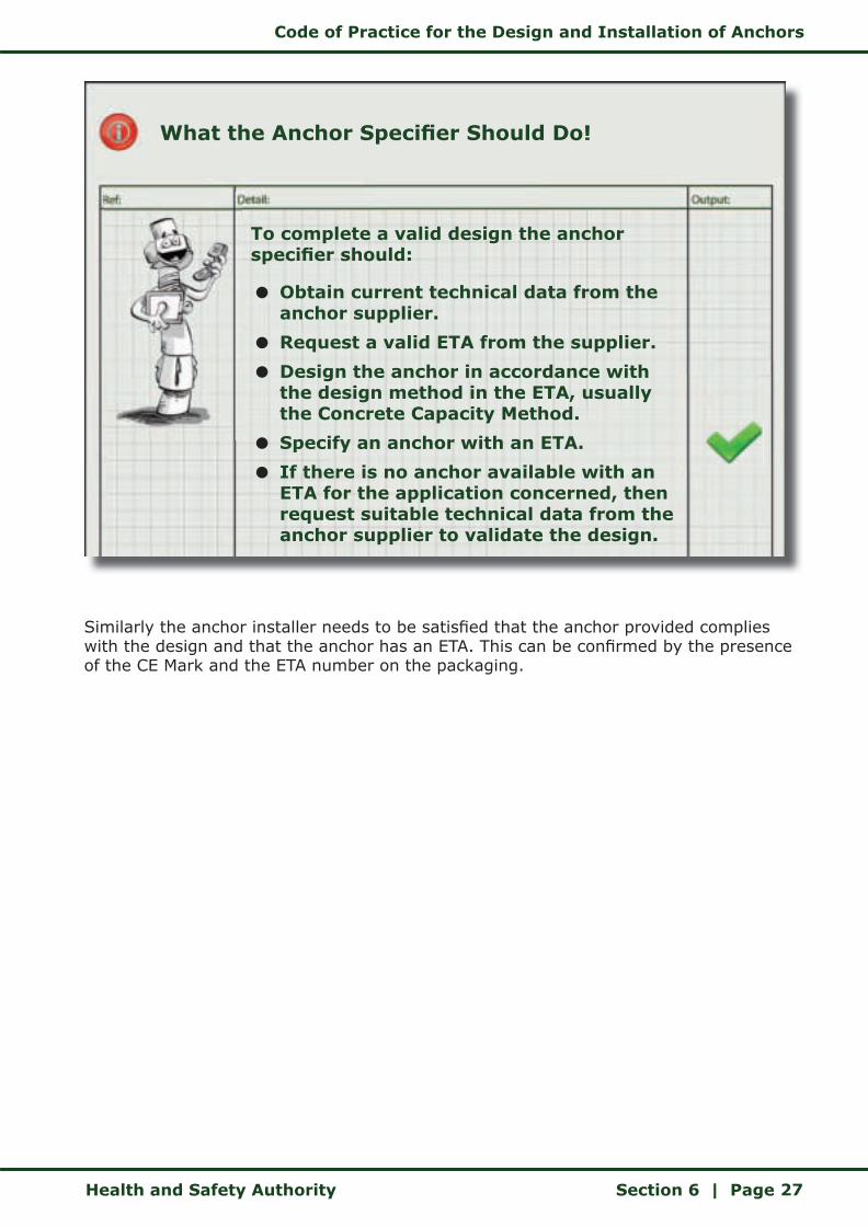
What the Anchor Specifier Should Do!
To complete a valid design the anchor specifier should:
z Obtain current technical data from the anchor supplier.
z Request a valid ETA from the supplier.
z Design the anchor in accordance with the design method in the ETA, usually the Concrete Capacity Method.
z Specify an anchor with an ETA.
z If there is no anchor available with an ETA for the application concerned, then request suitable technical data from the anchor supplier to validate the design.
Code of Practice for the Design and Installation of Anchors
Section 6 | Page Health and Safety Authority28
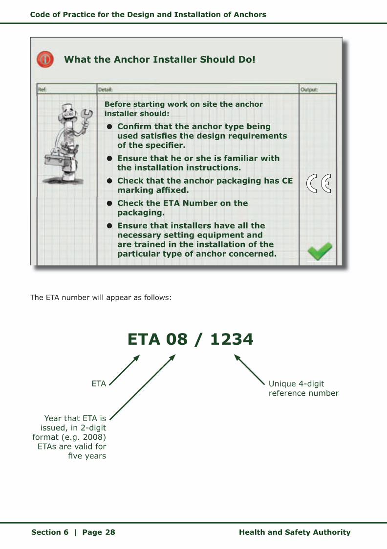
The ETA number will appear as follows:
What the Anchor Installer Should Do!
Before starting work on site the anchor installer should:
z Confirm that the anchor type being used satisfies the design requirements of the specifier.
z Ensure that he or she is familiar with the installation instructions.
z Check that the anchor packaging has CE marking affixed.
z Check the ETA Number on the packaging.
z Ensure that installers have all the necessary setting equipment and are trained in the installation of the particular type of anchor concerned.
ETA 08 / 1234
ETA
Year that ETA is issued, in 2-digit
format (e.g. 2008)ETAs are valid for
five years
Unique 4-digit reference number
Code of Practice for the Design and Installation of Anchors
Health and Safety Authority Section 7 | Page 29
7 ROLES AND RESPONSIBILITIES
7.1 General
The following persons are likely to be involved during different stages of the anchor selection, design and installation and have responsibilities for providing the correct information, producing the correct specification and correctly installing the anchor on site.
z Anchor manufacturer/supplier.
z Anchor specifier (for permanent or temporary anchors).
z Anchor installer.
Situations may arise on site where a person makes a decision in relation to the anchor, for example to change the anchor type. In such a situation that person is an anchor specifier and must comply with this code of practice.
Specific responsibilities for the management of health and safety during this process lie with the:
z Project supervisor design process.
z Contractor (note that a contractor in charge of a place of work may engage other contractors to undertake the actual installation of the anchor).
z Project supervisor construction stage.
The Safety, Health and Welfare at Work (Construction) Regulations 2006 impose specific statutory duties irrespective of the contractual arrangements that may exist between the different parties. The regulations require cooperation between the different persons and the coordination of activities to avoid overlaps or gaps arising that could be confusing and/or dangerous. In addition there is a duty to monitor these activities and to take remedial action if required. Therefore it is essential that clear lines of communications are established between these different parties from the start of the project.
In addition to the provisions of the 2006 Construction Regulations, anchors are also governed by the provisions of the Safety, Health and Welfare at Work Act 2005, sections 16 and 17.
7.1 Anchor Manufacturer/Anchor Supplier:
Under the Safety, Health and Welfare at Work Act 2005, each anchor manufacturer and supplier is required to ensure that the anchors supplied are designed and manufactured so as to be safe and without risk to health, on the basis that the anchor is subsequently:
z Specified properly by the anchor specifier, in accordance with ETAG 001 and the data contained in the ETA. This information may also be available in the manufacturer’s technical manual.
z Installed properly by the installer, in accordance with the manufacturer’s instructions.
Code of Practice for the Design and Installation of Anchors
Section 7 | Page Health and Safety Authority30
Anchor suppliers are required to provide such information as is necessary for the specifier and the installer to ensure the anchor’s safe installation, use, maintenance, cleaning, dismantling or disposal, without risk to safety or health.
Anchor manufacturers submit each anchor to undergo stringent tests to establish the parameters for its safe use. This is particularly the case with anchors that have achieved European Technical Approval. Therefore ETA anchors specified and installed in accordance with the manufacturer’s instructions may not require additional site testing.
Anchor suppliers have a range of information available, which the specifier and installer should request, including:
z ETAs.
z Test reports, if the anchor is to be installed in base materials other than concrete or where the quality or strength of the base material is unknown.
z Technical manuals.
z Technical data sheets.
z Design data, including anchor capacities for different load conditions.
z Computer aided anchor design software.
z Design guides.
z Installation instructions.
z Safety data sheets.
z Safety instructions.
z Installation instructions in pictogram format on the anchor packaging.
z Fire behaviour.
In addition, anchor suppliers will often provide technical advice and support for the design, specification and installation of their products.
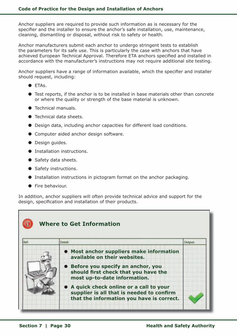
Where to Get Information
z Most anchor suppliers make information available on their websites.
z Before you specify an anchor, you should first check that you have the most up-to-date information.
z A quick check online or a call to your supplier is all that is needed to confirm that the information you have is correct.

Code of Practice for the Design and Installation of Anchors
Health and Safety Authority Section 7 | Page 31
7.2 Anchor Specifier
The anchor specifier must ensure, as far as reasonably practicable, that any risks to safety or health are eliminated or minimised in the design. In order to do this the anchor specifier must determine the most appropriate anchor for the particular application and determine the appropriate design method for that anchor. The anchor supplier will be able to provide technical assistance to the specifier in this regard. The specifier must complete the design in accordance with the chosen design method (Global Safety Factor or Partial Safety Factor). The design must take into account the most onerous loads that the anchor will be subjected to and the direction of the loads.
Anchors are often used in temporary situations to provide fixing points for units or operatives over a short duration. It is important to stress that the scope of this code of practice covers the use of anchors in Safety Critical Situations where their failure may cause serious injury or death. Whether the anchors are being used in a temporary or permanent capacity is irrelevant in the context of the consequence of an anchor failure.
The design of temporary anchors may differ slightly from permanent anchors. For example the base concrete material used may not have had the standard 28-day curing time and consequently the specifier should use a reduced concrete strength in calculating anchor capacities. The specifier must be satisfied that the actual partial safety factors used in the design of temporary anchors accurately reflect the specific use of the anchor on site. The anchor specifier must also take into account the range of additional loads that may act on the temporary anchor during use.
If the specifier considers that the consequence of failure of a temporary anchor is such that serious injury or death may be likely to occur, then this code must be followed in the design and installation of that anchor. Once the design calculations are completed and checked, the specifier can proceed to specify the anchor. In this case the specifier must specify the anchor explicitly and completely, so that the anchor installed on site matches the design criteria.
When Specifying an Anchor
z Get the most up-to-date design information from the supplier.
z Decide on the design approach: Partial Safety Factor or Global Safety Factor.
z Complete the design and get it checked.
z Communicate the design in clear and unambiguous terms.
Code of Practice for the Design and Installation of Anchors
Section 7 | Page Health and Safety Authority32
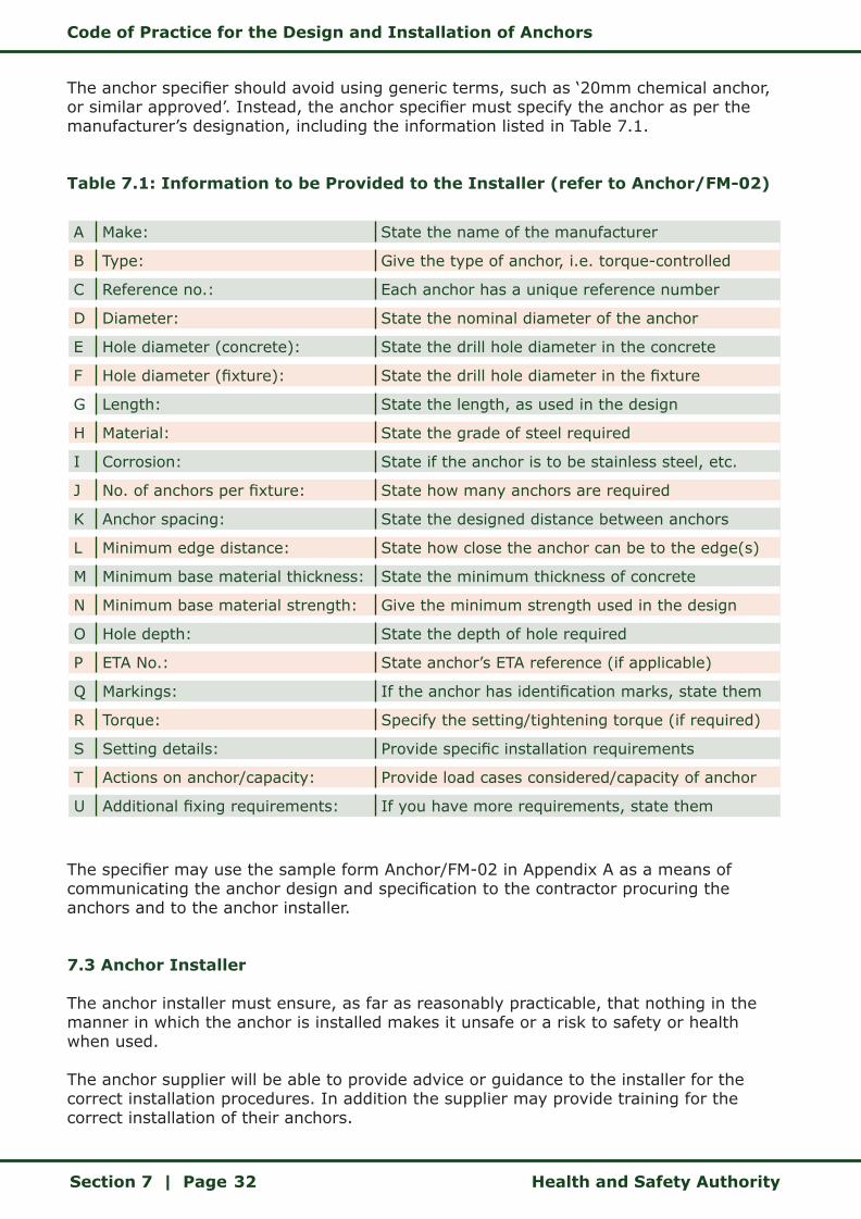
The anchor specifier should avoid using generic terms, such as ‘20mm chemical anchor, or similar approved’. Instead, the anchor specifier must specify the anchor as per the manufacturer’s designation, including the information listed in Table 7.1.
Table 7.1: Information to be Provided to the Installer (refer to Anchor/FM-02)
A Make: State the name of the manufacturer
B Type: Give the type of anchor, i.e. torque-controlled
C Reference no.: Each anchor has a unique reference number
D Diameter: State the nominal diameter of the anchor
E Hole diameter (concrete): State the drill hole diameter in the concrete
F Hole diameter (fixture): State the drill hole diameter in the fixture
G Length: State the length, as used in the design
H Material: State the grade of steel required
I Corrosion: State if the anchor is to be stainless steel, etc.
J No. of anchors per fixture: State how many anchors are required
K Anchor spacing: State the designed distance between anchors
L Minimum edge distance: State how close the anchor can be to the edge(s)
M Minimum base material thickness: State the minimum thickness of concrete
N Minimum base material strength: Give the minimum strength used in the design
O Hole depth: State the depth of hole required
P ETA No.: State anchor’s ETA reference (if applicable)
Q Markings: If the anchor has identification marks, state them
R Torque: Specify the setting/tightening torque (if required)
S Setting details: Provide specific installation requirements
T Actions on anchor/capacity: Provide load cases considered/capacity of anchor
U Additional fixing requirements: If you have more requirements, state them
The specifier may use the sample form Anchor/FM-02 in Appendix A as a means of communicating the anchor design and specification to the contractor procuring the anchors and to the anchor installer.
7.3 Anchor Installer
The anchor installer must ensure, as far as reasonably practicable, that nothing in the manner in which the anchor is installed makes it unsafe or a risk to safety or health when used.
The anchor supplier will be able to provide advice or guidance to the installer for the correct installation procedures. In addition the supplier may provide training for the correct installation of their anchors.

Code of Practice for the Design and Installation of Anchors
Health and Safety Authority Section 7 | Page 33
The installer must have referred to the anchor installation instructions, which are on the packaging and available from the supplier, prior to commencing the work. The anchor installer must ensure that the correct drilling and setting tools are available for the proper installation of the anchor. Steps in the installation procedure must not be omitted or partially undertaken, for example failing to blow out the drill hole prior to setting the anchor.
Installation instructions are provided on the technical data sheets and on the anchor’s packaging. The material safety data sheet should also be referred to if the anchor system includes components that could be hazardous to safety or health. These are available from the anchor supplier/manufacturer.
The person installing the anchor must have received the appropriate instructions for the correct installation of the particular anchor and the installation must be supervised by a competent person appointed by the contractor, so as to ensure that the anchor is installed in accordance with the manufacturer’s instructions. In this context, the anchor installer must be made aware of the consequences of failing to adhere to the correct installation instructions.
The installer should not proceed with the installation of the anchor if, due to site conditions, it cannot be set in accordance with the manufacturer’s instructions. The conflict should be referred back to the anchor specifier and the anchor supplier, so that a solution can be designed and an alternative anchor or an alternative method can be specified.
The anchor installer may use the sample form Anchor/FM-03 in Appendix A as a means of recording the correct installation of the specified anchor.
7.4 Project Supervisor Design Process (PSDP)
The PSDP has a responsibility under the Safety, Health and Welfare at Work (Construction) Regulations 2006 to take reasonable steps to bring about co-operation between designers on the same project and to ensure, as far as reasonably practicable, coordination of their activities in relation to the design of the project with a view to protecting persons at work. In this respect, the PDSP should coordinate the activities of the anchor specifier with those of other designers, irrespective of whether the anchors are permanent or temporary.
The PSDP should coordinate sign-off of the anchor design with the anchor specifier. This can be done using either a permanent works design certificate or a temporary works design certificate, or with a similar project-specific certificate. Examples of permanent and temporary works design certificates are contained in the Guidelines on the Procurement, Design and Management Requirements of the Safety Health and Welfare at Work (Construction) Regulations 2006.
7.5 Contractor
The contractor should ensure that the specified anchor is procured and that the anchor installer is trained for the correct installation of that anchor type. In addition the contractor should ensure that the installer is working under competent supervision.
Code of Practice for the Design and Installation of Anchors
Section 7 | Page Health and Safety Authority34
7.6 Project Supervisor Construction Stage (PSCS)
The PSCS is required to coordinate the implementation of the Safety, Health and Welfare at Work (Construction) Regulations 2006 and therefore the activities of contractors engaged in the installation of anchors.
The PSCS should ensure that the installation of anchors is coordinated with the activities of other contractors. The PSCS should also ensure that the appropriate contractor completes form Anchor/FM-03 (see Appendix A).
Code of Practice for the Design and Installation of Anchors
Health and Safety Authority Section 8 | Page 35
8 DESIGN AND SPECIFICATION OF ANCHORS
8.1 General
The information supplied here is intended to give the design engineer a basic knowledge of the design factors that need to be taken into account when selecting an anchor for any safety critical application.
The Safety, Health and Welfare at Work Act 2005 stipulates that:
2.-(2)(a) For the purposes of the relevant statutory provisions, a person is deemed to be a competent person where, having regard to the task he or she is required to perform and taking account of the size or hazards (or both of them) of the undertaking or establishment in which he or she undertakes work, the person possesses sufficient training, experience and knowledge appropriate to the nature of the work to be undertaken.
In the context of the design or specification of anchors, the employer should ensure that the person specifying the anchor has the following:
Training
z This may be in the form of in-house training in the use of the design software or technical manuals. Alternatively it may involve attending seminars provided by anchor suppliers. It may also be considered as formal training provided in structural design or partial safety factor design in accordance with Eurocodes.
Knowledge
z The anchor specifier should have a working knowledge of the technical manuals and the design software provided. If the anchor specifier is using particular software for the first time, guidance should be sought from another specifier who has knowledge of the software or from the anchor supplier directly.
Experience
z The anchor specifier should have experience of designing anchors of the type being considered. If the anchor specifier lacks direct experience, guidance should be sought from another specifier who has experience of the anchor type or from the anchor supplier directly.
ETAG 001, Annex C, provides a sophisticated design concept, including three design methods. In order to gain optimum performance of the anchor and at the same time an economical design, the Concrete Capacity Method distinguishes between different load directions (tension, shear, combined tension and shear) and provides design models and
2.-(2)(a) For the purposes of the relevant statutory provisions, a person is deemed to be a competent person where, having regard to the task he or she is required to perform and taking account of the size or hazards (or both of them) of the undertaking or establishment in which he or she undertakes work, the person possesses sufficient training, experience and knowledge appropriate to the nature of the work to be undertaken.
Code of Practice for the Design and Installation of Anchors
Section 8 | Page Health and Safety Authority36
advice on the following different failure modes:
z Tension load:
z Steel failure.
z Concrete cone failure.
z Pull-out/pull-through failure.
z Splitting failure.
z Shear load:
z Steel failure.
z Concrete edge failure.
z Pryout failure.
The specification of the correct anchor for a specific application is something which cannot be over stressed. The anchor specifier should seek the most current technical data from the anchor manufacturer, together with the ETA. If the anchor specifier has any doubt about an anchor selection he or she should always contact the manufacturer for technical advice.
When selecting an anchor for a particular application there are a number of factors that need to be addressed by the anchor specifier, as set out below.
8.2 Type of Base Material
8.2.1 Concrete
When a mixture of cement, aggregates and water hardens and cures it becomes concrete. Concrete is the base material into which most structural connections are made and for which most anchors are designed. Manufacturers’ performance values are generally quoted for a concrete base material.
Performance is most commonly quoted for C20/25 grade concrete, however, the higher option ETA allows for increased capacities for higher concrete strength up to C50/60. Using the Concrete Capacity Method in ETAG 001, Annex C, it is possible to calculate the increased load capacity of an anchor installed in higher strength concrete.
8.2.2 Cracked/Non-cracked Concrete
Concrete may be cracked for a variety of reasons, mainly due to the loading of the structure (cracked concrete in the tension zone, non-cracked in the compression zone). Steel reinforcement bars are cast in the concrete to take up the tensile forces. ETAG 001 differentiates between anchors approved for use in both cracked and non-cracked concrete. The correct anchor type should be selected to suit the concrete condition.
The performance for most anchors is usually quoted for non-reinforced concrete. In general, reinforcement does not improve anchor performance. If reinforcement is hit during the drilling process then the aborted hole should be filled with a strong non-shrink grout. The new hole should be located away from the aborted hole by at least the depth of the aborted hole.

Code of Practice for the Design and Installation of Anchors
Health and Safety Authority Section 8 | Page 37
8.2.3 Masonry
Masonry panels can be awkward materials to fix into. The strength can vary from 5 to 70N/mm2, masonry units may be solid or have perforations and the mortar may be weak or non-existent in parts of the joints.
Bonded (especially injection-type) anchors are particularly suitable as they exert no expansion stresses in the base material and will also fill any small voids present. If considering a mechanical anchor, the most appropriate metal anchors are thin-walled sleeve anchors, which exert low expansion stresses and are less likely to crack weak bricks than anchors with thick expanders. Special plastic anchors may also be suitable.
There is currently no load data available for the design of anchors for masonry base materials and there are no anchors available with an ETA for use in masonry units produced in Ireland. It is anticipated that in the future there may be bonded anchors for use in masonry, which will be covered by the principles in EOTA TR029. When available, these anchors should be designed in accordance with their ETA.
In the interim, given the large variation in the strength of this base material and the difficulty in determining the resistance of the base material to anchor loads, it is not considered safe to specify or install safety critical anchors into masonry panels.
In the case of base materials other than concrete, the anchor specifier may consider other options, such as incorporating sufficiently sized concrete pad stones into the masonry panels, in order to facilitate the use of ETA anchors.
Outside the scope of this code, there are plastic anchors for non-structural use in masonry, which are covered by ETAG 020 (Part 3 relates to plastic anchors in solid masonry panels and Part 4 to plastic anchors in hollow or perforated masonry panels).
8.3 Load Type
When considering the load type, the anchor specifier needs to decide if there is a tensile, shear or combined load acting on the anchor(s). In addition the anchor specifier may need to consider bending moments acting on the anchor. For example in the case of stand-off anchor applications, where the load is acting on the anchor at a distance from the surface of the base material, thus imposing bending moments. The manufacturers publish resistances in their technical data as a result of exhaustive tests using recognised test procedures (ETAG 001, Annex A: Details of tests). Recommended loads are commonly derived from characteristic loads subject to a global safety factor. ETAs quote characteristic loads together with the partial safety factors needed to derive the design resistances of the anchor, for all possible anchor failure modes.
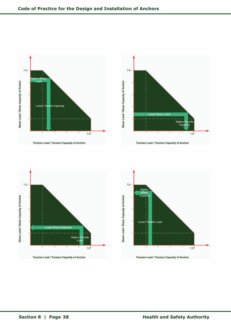
8.4 Load Direction
The magnitude of the load applied to an anchor must be less than the manufacturer’s recommended load in the direction concerned. According to ETAG 001, Annex C, the applied load multiplied by a partial safety factor must be smaller than the characteristic resistance of the anchor divided by a partial safety factor. In the case of combined loads a check must be carried out to ensure that the resolved components are less than the recommended tensile and shear loads without exceeding the capacity in the direction concerned.
Code of Practice for the Design and Installation of Anchors
Section 8 | Page Health and Safety Authority38
Code of Practice for the Design and Installation of Anchors
Health and Safety Authority Section 8 | Page 39
Some anchors are noticeably stronger in shear than in tension. For example, heavy-duty sleeve anchors or thick-walled sleeve anchors.
8.5 Edge and Anchor Spacing
The next step in the design process is to look at the effect of anchor spacing and edge distances on the anchor. When a tensile load is applied to an anchor it creates a stress cone in the concrete, which will resist this applied load. For anchors in tension, the concrete cone capacity is determined by the tensile strength of the stress cone in the concrete surrounding the anchor. The size of the cone is a function of the setting depth and is measured by the area of the cone base at the concrete surface.
For anchor groups, these surface areas may overlap resulting in a combined cone that will have a capacity less than the capacity of a single anchor, multiplied by the number of anchors in the group.
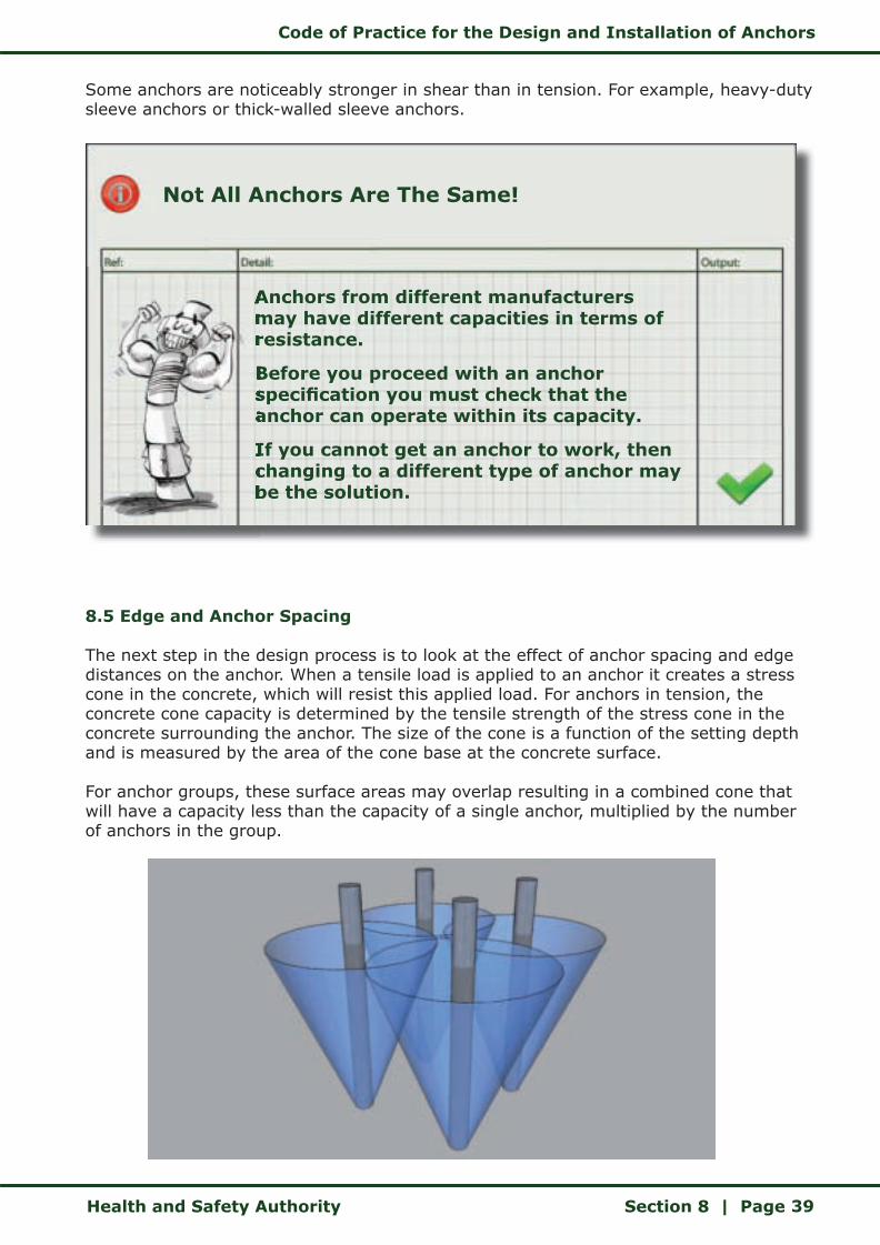
Not All Anchors Are The Same!
Anchors from different manufacturers may have different capacities in terms of resistance.
Before you proceed with an anchor specification you must check that the anchor can operate within its capacity.
If you cannot get an anchor to work, then changing to a different type of anchor may be the solution.
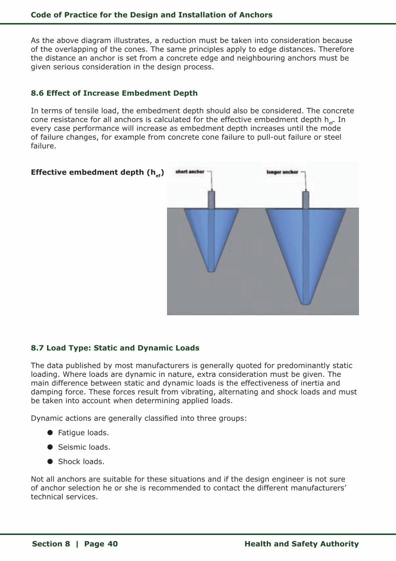
Code of Practice for the Design and Installation of Anchors
Section 8 | Page Health and Safety Authority40
As the above diagram illustrates, a reduction must be taken into consideration because of the overlapping of the cones. The same principles apply to edge distances. Therefore the distance an anchor is set from a concrete edge and neighbouring anchors must be given serious consideration in the design process.
8.6 Effect of Increase Embedment Depth
In terms of tensile load, the embedment depth should also be considered. The concrete cone resistance for all anchors is calculated for the effective embedment depth hef. In every case performance will increase as embedment depth increases until the mode of failure changes, for example from concrete cone failure to pull-out failure or steel failure.
Effective embedment depth (hef)
8.7 Load Type: Static and Dynamic Loads
The data published by most manufacturers is generally quoted for predominantly static loading. Where loads are dynamic in nature, extra consideration must be given. The main difference between static and dynamic loads is the effectiveness of inertia and damping force. These forces result from vibrating, alternating and shock loads and must be taken into account when determining applied loads.
Dynamic actions are generally classified into three groups:
z Fatigue loads.
z Seismic loads.
z Shock loads.
Not all anchors are suitable for these situations and if the design engineer is not sure of anchor selection he or she is recommended to contact the different manufacturers’ technical services.
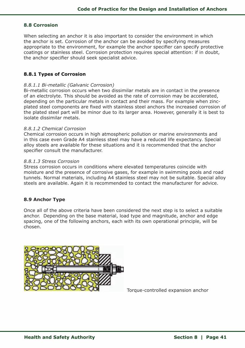
Code of Practice for the Design and Installation of Anchors
Health and Safety Authority Section 8 | Page 41
8.8 Corrosion
When selecting an anchor it is also important to consider the environment in which the anchor is set. Corrosion of the anchor can be avoided by specifying measures appropriate to the environment, for example the anchor specifier can specify protective coatings or stainless steel. Corrosion protection requires special attention: if in doubt, the anchor specifier should seek specialist advice.
8.8.1 Types of Corrosion
8.8.1.1 Bi-metallic (Galvanic Corrosion)Bi-metallic corrosion occurs when two dissimilar metals are in contact in the presence of an electrolyte. This should be avoided as the rate of corrosion may be accelerated, depending on the particular metals in contact and their mass. For example when zinc-plated steel components are fixed with stainless steel anchors the increased corrosion of the plated steel part will be minor due to its larger area. However, generally it is best to isolate dissimilar metals.
8.8.1.2 Chemical Corrosion Chemical corrosion occurs in high atmospheric pollution or marine environments and in this case even Grade A4 stainless steel may have a reduced life expectancy. Special alloy steels are available for these situations and it is recommended that the anchor specifier consult the manufacturer.
8.8.1.3 Stress CorrosionStress corrosion occurs in conditions where elevated temperatures coincide with moisture and the presence of corrosive gases, for example in swimming pools and road tunnels. Normal materials, including A4 stainless steel may not be suitable. Special alloy steels are available. Again it is recommended to contact the manufacturer for advice.
8.9 Anchor Type
Once all of the above criteria have been considered the next step is to select a suitable anchor. Depending on the base material, load type and magnitude, anchor and edge spacing, one of the following anchors, each with its own operational principle, will be chosen.
Torque-controlled expansion anchor
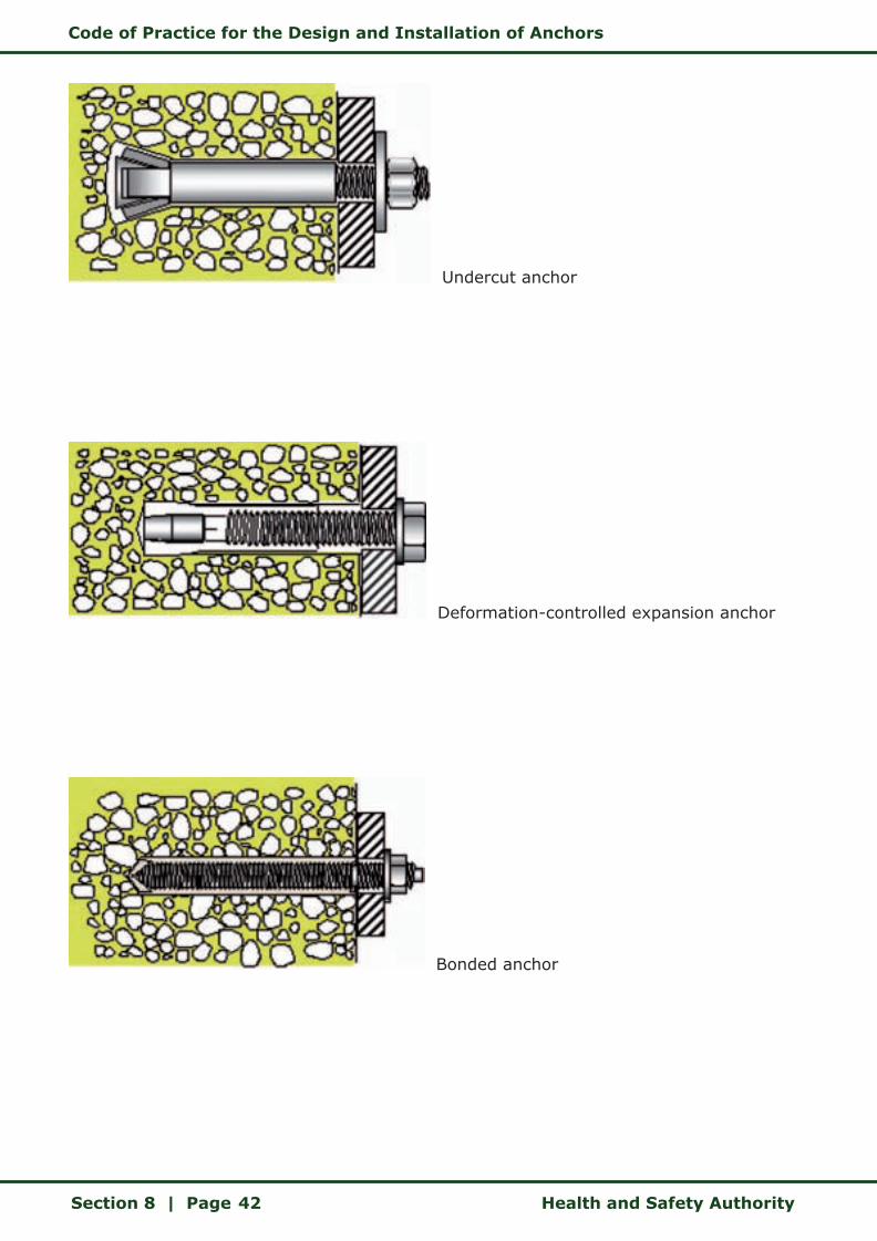
Code of Practice for the Design and Installation of Anchors
Section 8 | Page Health and Safety Authority42
Undercut anchor
Deformation-controlled expansion anchor
Bonded anchor
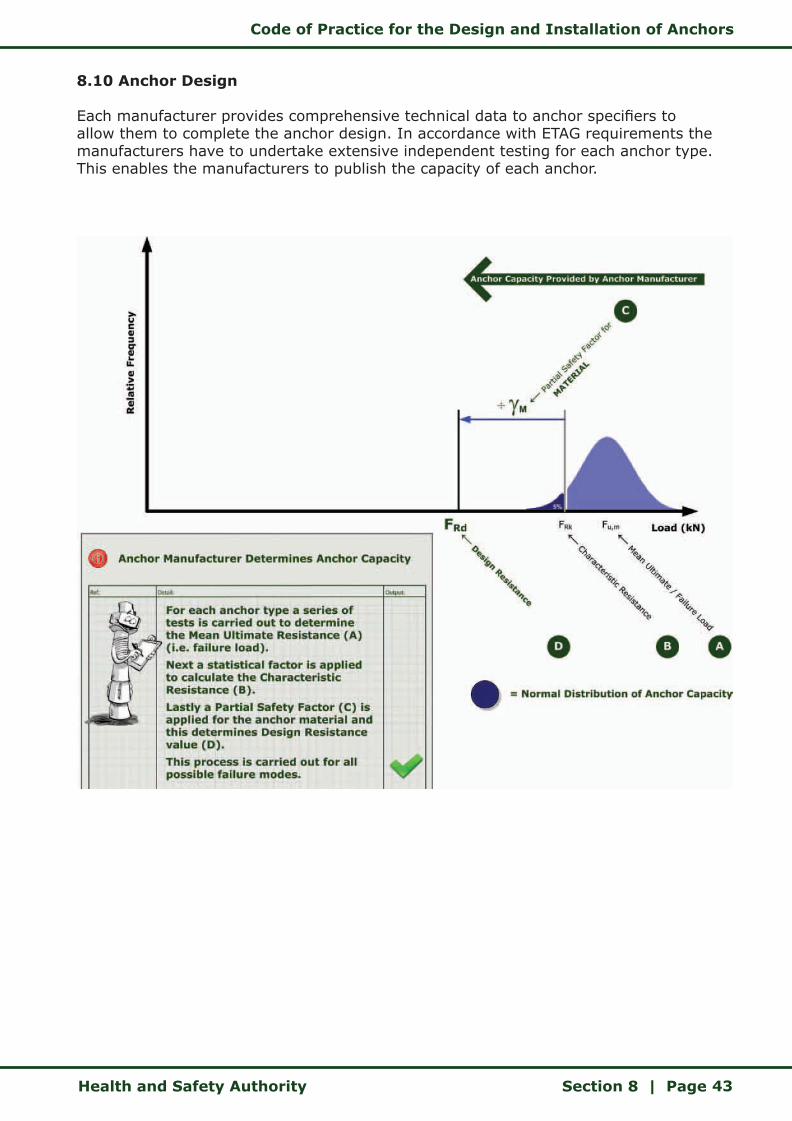
Code of Practice for the Design and Installation of Anchors
Health and Safety Authority Section 8 | Page 43
8.10 Anchor Design
Each manufacturer provides comprehensive technical data to anchor specifiers to allow them to complete the anchor design. In accordance with ETAG requirements the manufacturers have to undertake extensive independent testing for each anchor type. This enables the manufacturers to publish the capacity of each anchor.
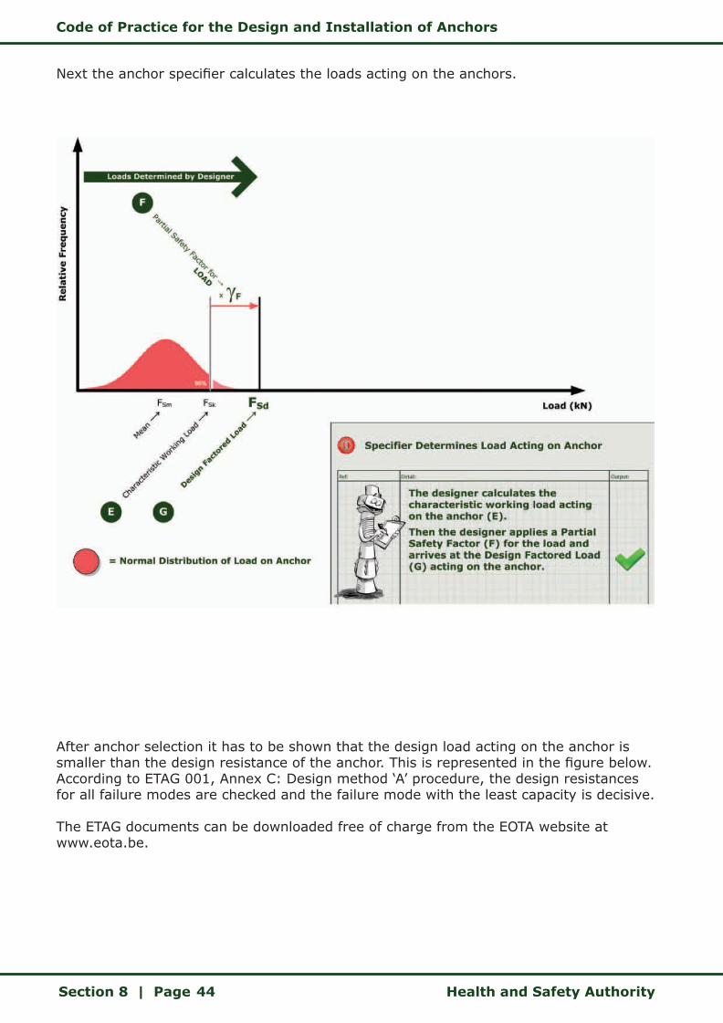
Code of Practice for the Design and Installation of Anchors
Section 8 | Page Health and Safety Authority44
Next the anchor specifier calculates the loads acting on the anchors.
After anchor selection it has to be shown that the design load acting on the anchor is smaller than the design resistance of the anchor. This is represented in the figure below. According to ETAG 001, Annex C: Design method ‘A’ procedure, the design resistances for all failure modes are checked and the failure mode with the least capacity is decisive.
The ETAG documents can be downloaded free of charge from the EOTA website at www.eota.be.
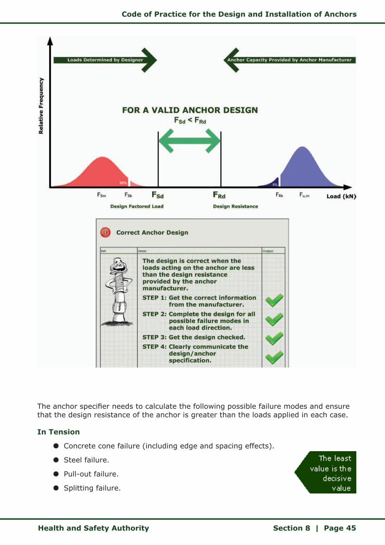
Code of Practice for the Design and Installation of Anchors
Health and Safety Authority Section 8 | Page 45
The anchor specifier needs to calculate the following possible failure modes and ensure that the design resistance of the anchor is greater than the loads applied in each case.
In Tension
z Concrete cone failure (including edge and spacing effects).
z Steel failure.
z Pull-out failure.
z Splitting failure.
Code of Practice for the Design and Installation of Anchors
Section 8 | Page Health and Safety Authority46
In Shear:
z Steel failure (with and without lever arm).
z Pryout failure (including edge and spacing effects).
z Concrete edge failure (including edge and spacing effects).
All loading stages are to be identified by the anchor specifier at design stage. The anchor specifier shall consider the stresses experienced by the anchor throughout its lifespan.
Some manufacturers offer computer-aided software for the design of anchors according to the Partial Safety Factor design procedure. This greatly helps the anchor specifier to save time and costs for anchor design.
Caution should be exercised in the use of the anchor design software, as a number of options are presented to the anchor specifier, the choice of which has considerable impact on the resultant output. Knowledge of ETAG 001, Annex C, will enable the specifier to verify the output from the design software.
The anchor specifier should ensure that the person inputting data into the computer has the requisite training, knowledge and experience, so that the anchor design will comply with the design assumptions and the site conditions.
There are three basic scenarios that can exist when specifying anchors:
z An anchor is not safety critical.
z An anchor is being used in a Safety Critical Situation and is being designed and specified by the designer.
z An anchor is being used in a Safety Critical Situation and while the designer will identify the need for the anchor, it will be designed and specified by the anchor manufacturer/supplier.
These three scenarios are summarised on the following pages.
Caution should be exercised in the use of the anchor design software, as a number of options are presented to the anchor specifier, the choice of which has considerable impact on the resultant output. Knowledge of ETAG 001, Annex C, will enable the specifier to verify the output from the design software.
The anchor specifier should ensure that the person inputting data into the computer has the requisite training, knowledge and experience, so that the anchor design will comply with the design assumptions and the site conditions.
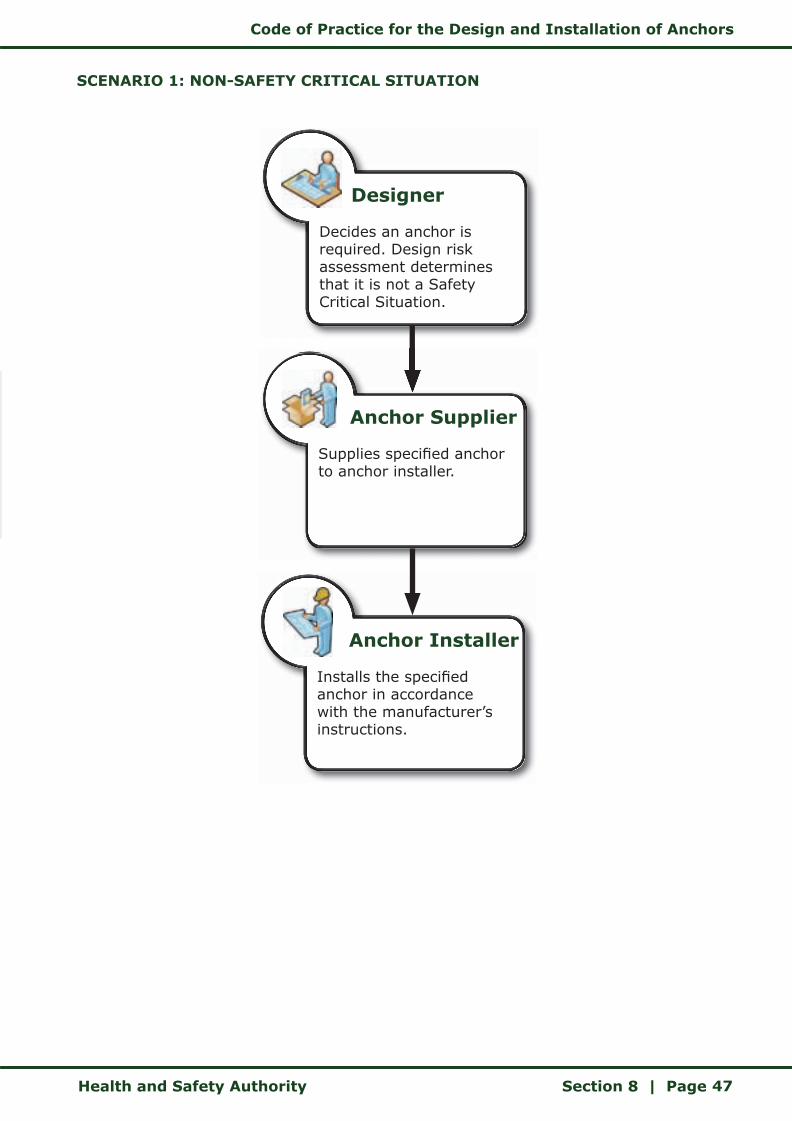
Code of Practice for the Design and Installation of Anchors
Health and Safety Authority Section 8 | Page 47
SCENARIO 1: NON-SAFETY CRITICAL SITUATION
Designer
Decides an anchor is required. Design risk assessment determines that it is not a Safety Critical Situation.
Anchor Supplier
Supplies specified anchor to anchor installer.
Anchor Installer
Installs the specified anchor in accordance with the manufacturer’s instructions.
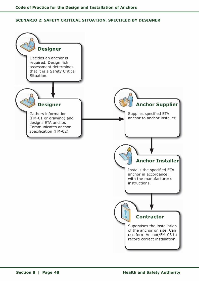
Code of Practice for the Design and Installation of Anchors
Section 8 | Page Health and Safety Authority48
SCENARIO 2: SAFETY CRITICAL SITUATION, SPECIFIED BY DESIGNER
Designer
Decides an anchor is required. Design risk assessment determines that it is a Safety Critical Situation.
Designer
Gathers information (FM-01 or drawing) and designs ETA anchor. Communicates anchor specification (FM-02).
Anchor Installer
Installs the specified ETA anchor in accordance with the manufacturer’s instructions.
Anchor Supplier
Supplies specified ETA anchor to anchor installer.
Contractor
Supervises the installation of the anchor on site. Can use form Anchor/FM-03 to record correct installation.
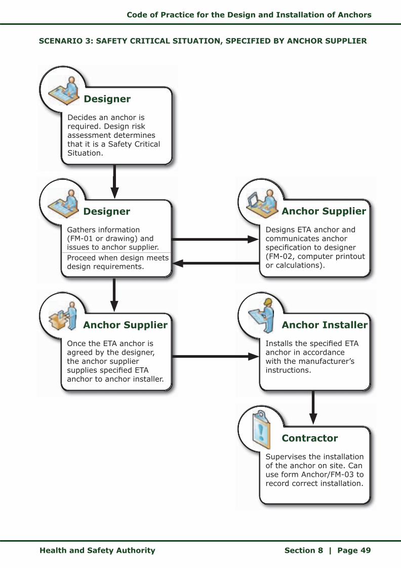
Code of Practice for the Design and Installation of Anchors
Health and Safety Authority Section 8 | Page 49
SCENARIO 3: SAFETY CRITICAL SITUATION, SPECIFIED BY ANCHOR SUPPLIER
Designer
Decides an anchor is required. Design risk assessment determines that it is a Safety Critical Situation.
Designer
Gathers information (FM-01 or drawing) and issues to anchor supplier.Proceed when design meets design requirements.
Anchor Installer
Installs the specified ETA anchor in accordance with the manufacturer’s instructions.
Anchor Supplier
Designs ETA anchor and communicates anchor specification to designer (FM-02, computer printout or calculations).
Contractor
Supervises the installation of the anchor on site. Can use form Anchor/FM-03 to record correct installation.
Anchor Supplier
Once the ETA anchor is agreed by the designer, the anchor supplier supplies specified ETA anchor to anchor installer.
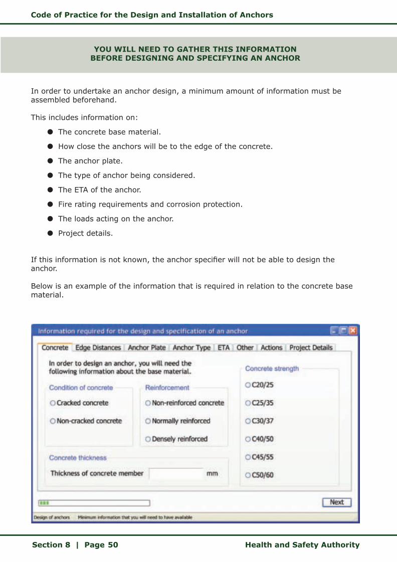
Code of Practice for the Design and Installation of Anchors
Section 8 | Page Health and Safety Authority50
YOU WILL NEED TO GATHER THIS INFORMATIONBEFORE DESIGNING AND SPECIFYING AN ANCHOR
In order to undertake an anchor design, a minimum amount of information must be assembled beforehand.
This includes information on:
z The concrete base material.
z How close the anchors will be to the edge of the concrete.
z The anchor plate.
z The type of anchor being considered.
z The ETA of the anchor.
z Fire rating requirements and corrosion protection.
z The loads acting on the anchor.
z Project details.
If this information is not known, the anchor specifier will not be able to design the anchor.
Below is an example of the information that is required in relation to the concrete base material.
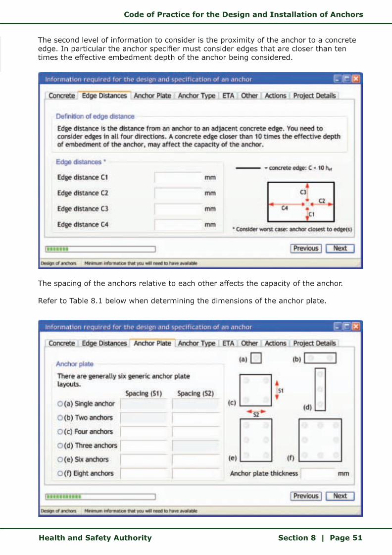
Code of Practice for the Design and Installation of Anchors
Health and Safety Authority Section 8 | Page 51
The second level of information to consider is the proximity of the anchor to a concrete edge. In particular the anchor specifier must consider edges that are closer than ten times the effective embedment depth of the anchor being considered.
The spacing of the anchors relative to each other affects the capacity of the anchor.
Refer to Table 8.1 below when determining the dimensions of the anchor plate.
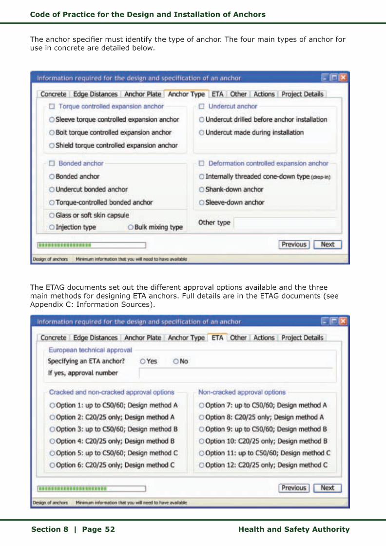
Code of Practice for the Design and Installation of Anchors
Section 8 | Page Health and Safety Authority52
The anchor specifier must identify the type of anchor. The four main types of anchor for use in concrete are detailed below.
The ETAG documents set out the different approval options available and the three main methods for designing ETA anchors. Full details are in the ETAG documents (see Appendix C: Information Sources).
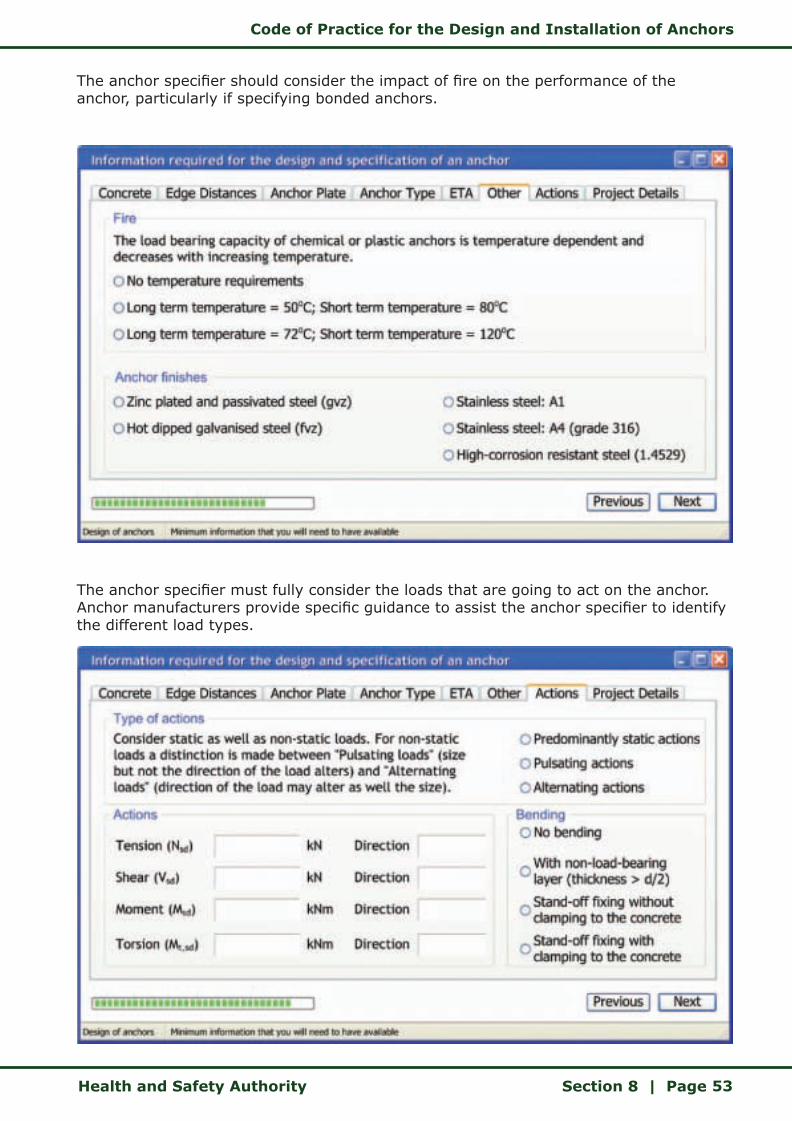
Code of Practice for the Design and Installation of Anchors
Health and Safety Authority Section 8 | Page 53
The anchor specifier should consider the impact of fire on the performance of the anchor, particularly if specifying bonded anchors.
The anchor specifier must fully consider the loads that are going to act on the anchor. Anchor manufacturers provide specific guidance to assist the anchor specifier to identify the different load types.
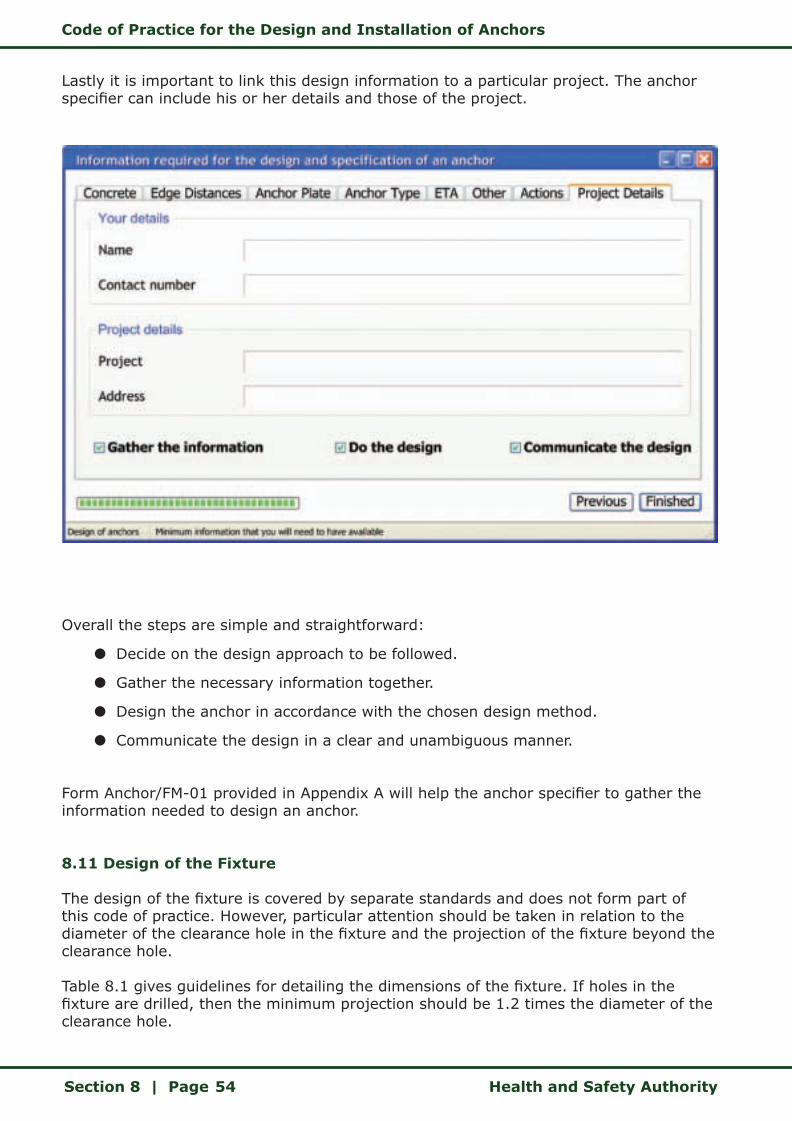
Code of Practice for the Design and Installation of Anchors
Section 8 | Page Health and Safety Authority54
Lastly it is important to link this design information to a particular project. The anchor specifier can include his or her details and those of the project.
Overall the steps are simple and straightforward:
z Decide on the design approach to be followed.
z Gather the necessary information together.
z Design the anchor in accordance with the chosen design method.
z Communicate the design in a clear and unambiguous manner.
Form Anchor/FM-01 provided in Appendix A will help the anchor specifier to gather the information needed to design an anchor.
8.11 Design of the Fixture
The design of the fixture is covered by separate standards and does not form part of this code of practice. However, particular attention should be taken in relation to the diameter of the clearance hole in the fixture and the projection of the fixture beyond the clearance hole.
Table 8.1 gives guidelines for detailing the dimensions of the fixture. If holes in the fixture are drilled, then the minimum projection should be 1.2 times the diameter of the clearance hole.
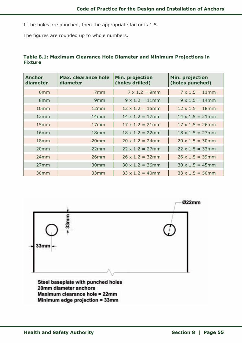
Code of Practice for the Design and Installation of Anchors
Health and Safety Authority Section 8 | Page 55
If the holes are punched, then the appropriate factor is 1.5.
The figures are rounded up to whole numbers.
Table 8.1: Maximum Clearance Hole Diameter and Minimum Projections in Fixture
Anchor diameter
Max. clearance hole diameter
Min. projection (holes drilled)
Min. projection (holes punched)
6mm 7mm 7 x 1.2 = 9mm 7 x 1.5 = 11mm
8mm 9mm 9 x 1.2 = 11mm 9 x 1.5 = 14mm
10mm 12mm 12 x 1.2 = 15mm 12 x 1.5 = 18mm
12mm 14mm 14 x 1.2 = 17mm 14 x 1.5 = 21mm
15mm 17mm 17 x 1.2 = 21mm 17 x 1.5 = 26mm
16mm 18mm 18 x 1.2 = 22mm 18 x 1.5 = 27mm
18mm 20mm 20 x 1.2 = 24mm 20 x 1.5 = 30mm
20mm 22mm 22 x 1.2 = 27mm 22 x 1.5 = 33mm
24mm 26mm 26 x 1.2 = 32mm 26 x 1.5 = 39mm
27mm 30mm 30 x 1.2 = 36mm 30 x 1.5 = 45mm
30mm 33mm 33 x 1.2 = 40mm 33 x 1.5 = 50mm

Code of Practice for the Design and Installation of Anchors
Section 9 | Page Health and Safety Authority56
9 INFORMATION SUPPLIED BY ANCHOR MANUFACTURER/SUPPLIER
The manufacturer and supplier of the anchor have a duty to provide standard fixing details and design data to both the specifier and the installer of the anchor, on request. The anchor should also be clearly labelled or marked with all relevant details required for its safe installation and intended use. Additional information regarding detailed anchor technology and design, ETA reports and safety data sheets, where applicable, should be made readily available.
Section 16 of the Safety, Health and Welfare at Work Act 2005 requires the anchor supplier to have this information available.
The anchor manufacturer/supplier should readily provide, on request, the following information for the design of anchors.
9.1 Fixing Features
z Material type used to manufacture the anchor (e.g. stainless steel, carbon steel).
z Basic loading data (for a single anchor) for each material type and size:
z Mean ultimate resistance. (Warning this figure should not be used in design)
z Characteristic resistance. (Warning this figure should not be used in design)
z Design Resistance.
z Recommended resistance.
Further Information
If you are unsure of the capacity of the anchor you are considering, please contact the supplier.
Despite appearances, not all anchors are the same!
Before you start designing please make sure you have up-to-date information and that you know how to use this information correctly.
Code of Practice for the Design and Installation of Anchors
Health and Safety Authority Section 9 | Page 57
z Setting details complete with dimensioned drawing.
z Installation equipment required to install anchor adequately.
z Setting operation detailing step-by-step procedures to install the anchor adequately.
z Anchor geometry and mechanical properties.
9.2 Data Required for Detailed Design
z Design method details (e.g. ETAG 001, Annex C, in accordance with Partial Safety concept, Eurocode 1).
z Minimum thickness of base material.
z Pull-out resistance or bond failure in the case of chemical anchors.
z Concrete cone resistance as a function of embedment depth.
z Minimum concrete edge and spacing criteria.
z Reduction factors as required for edge distance, spacing, concrete strength and load direction(s).
z Tensile and shear resistance of the steel.
z Formula for combined tensile and shear loading situation.
Each anchor manufacturer generally provides the required information in one or both of the following formats:
z Technical manuals.
z Anchor design software.
The anchor specifier must be competent to undertake the design of the anchor, in either determining the correct or relevant information from the technical data, or by the correct use of the computer-aided design software provided by the anchor manufacturer.
The anchor specifier should also be aware of associated information on anchor technology and design, ETA reports and safety data sheets, where applicable.
The following information should be clearly marked on the packaging or contained within the packaging of the anchor supplied by the manufacturer/supplier:
z Size and type of anchor.
z Base material suitability.
z Setting details.
z Setting operations.
z Curing time and temperatures (where applicable).
z Storage instructions (where applicable).
Code of Practice for the Design and Installation of Anchors
Section 9 | Page Health and Safety Authority58
Each anchor should be clearly marked, identifying type of anchor and manufacturer.
The anchor manufacturer makes technical information available to both the anchor specifier and the anchor installer to allow them to undertake their tasks. Specifiers and installers should consult with the anchor manufacturer/supplier if they have any doubt as to the choice of the appropriate anchor or about the correct installation procedures.
The following chart outlines the life cycle of an anchor.

Code of Practice for the Design and Installation of Anchors
Health and Safety Authority Section 9 | Page 59
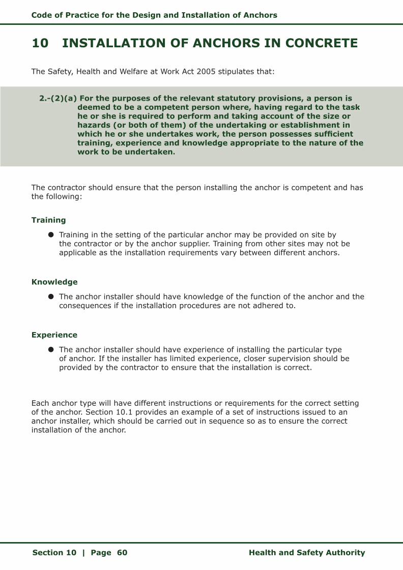
Code of Practice for the Design and Installation of Anchors
Section 10 | Page Health and Safety Authority60
10 INSTALLATION OF ANCHORS IN CONCRETE
The Safety, Health and Welfare at Work Act 2005 stipulates that:
2.-(2)(a) For the purposes of the relevant statutory provisions, a person is deemed to be a competent person where, having regard to the task he or she is required to perform and taking account of the size or hazards (or both of them) of the undertaking or establishment in which he or she undertakes work, the person possesses sufficient training, experience and knowledge appropriate to the nature of the work to be undertaken.
The contractor should ensure that the person installing the anchor is competent and has the following:
Training
z Training in the setting of the particular anchor may be provided on site by the contractor or by the anchor supplier. Training from other sites may not be applicable as the installation requirements vary between different anchors.
Knowledge
z The anchor installer should have knowledge of the function of the anchor and the consequences if the installation procedures are not adhered to.
Experience
z The anchor installer should have experience of installing the particular type of anchor. If the installer has limited experience, closer supervision should be provided by the contractor to ensure that the installation is correct.
Each anchor type will have different instructions or requirements for the correct setting of the anchor. Section 10.1 provides an example of a set of instructions issued to an anchor installer, which should be carried out in sequence so as to ensure the correct installation of the anchor.
2.-(2)(a) For the purposes of the relevant statutory provisions, a person is deemed to be a competent person where, having regard to the task he or she is required to perform and taking account of the size or hazards (or both of them) of the undertaking or establishment in which he or she undertakes work, the person possesses sufficient training, experience and knowledge appropriate to the nature of the work to be undertaken.
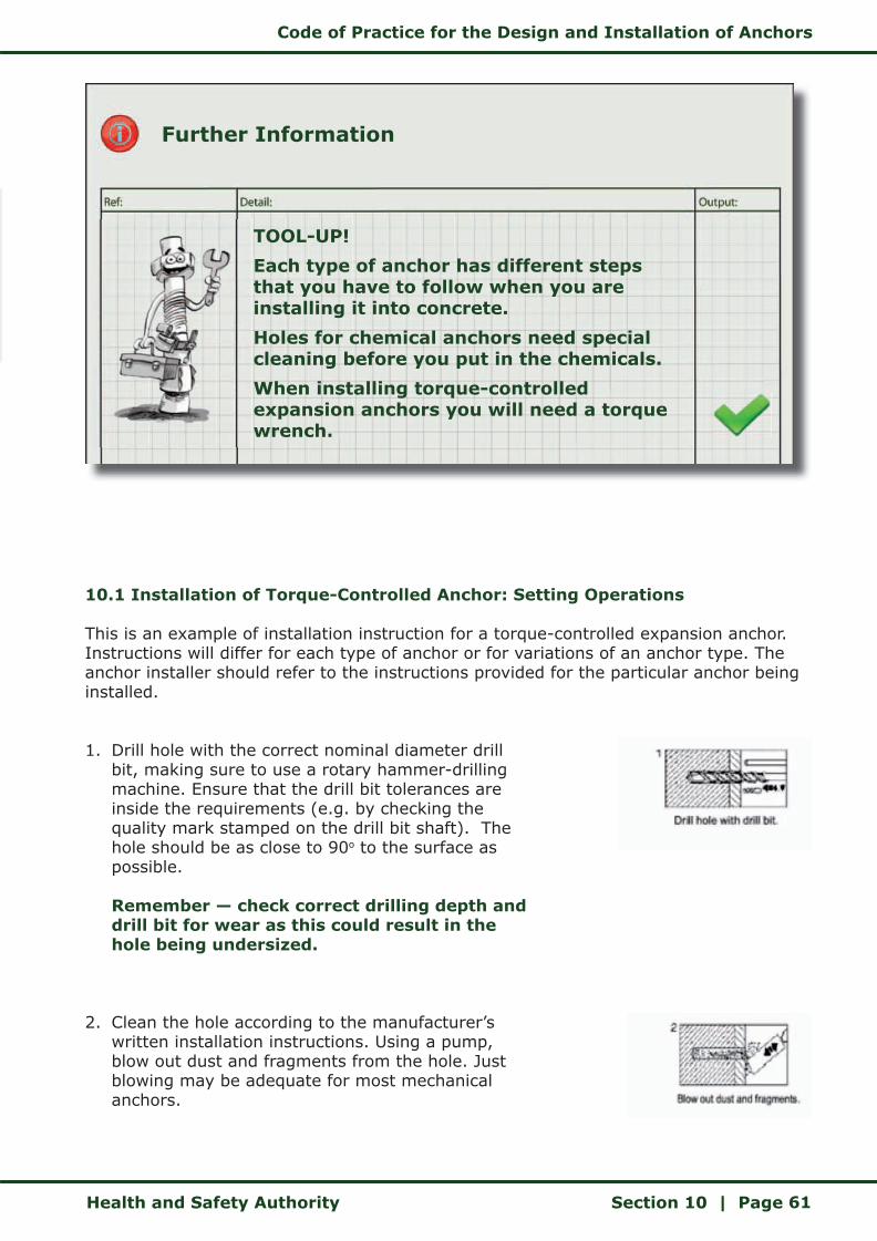
Code of Practice for the Design and Installation of Anchors
Health and Safety Authority Section 10 | Page 61
10.1 Installation of Torque-Controlled Anchor: Setting Operations
This is an example of installation instruction for a torque-controlled expansion anchor. Instructions will differ for each type of anchor or for variations of an anchor type. The anchor installer should refer to the instructions provided for the particular anchor being installed.
1. Drill hole with the correct nominal diameter drill bit, making sure to use a rotary hammer-drilling machine. Ensure that the drill bit tolerances are inside the requirements (e.g. by checking the quality mark stamped on the drill bit shaft). The hole should be as close to 90o to the surface as possible. Remember — check correct drilling depth and drill bit for wear as this could result in the hole being undersized.
2. Clean the hole according to the manufacturer’s written installation instructions. Using a pump, blow out dust and fragments from the hole. Just blowing may be adequate for most mechanical anchors.
Further Information
TOOL-UP!
Each type of anchor has different steps that you have to follow when you are installing it into concrete.
Holes for chemical anchors need special cleaning before you put in the chemicals.
When installing torque-controlled expansion anchors you will need a torque wrench.
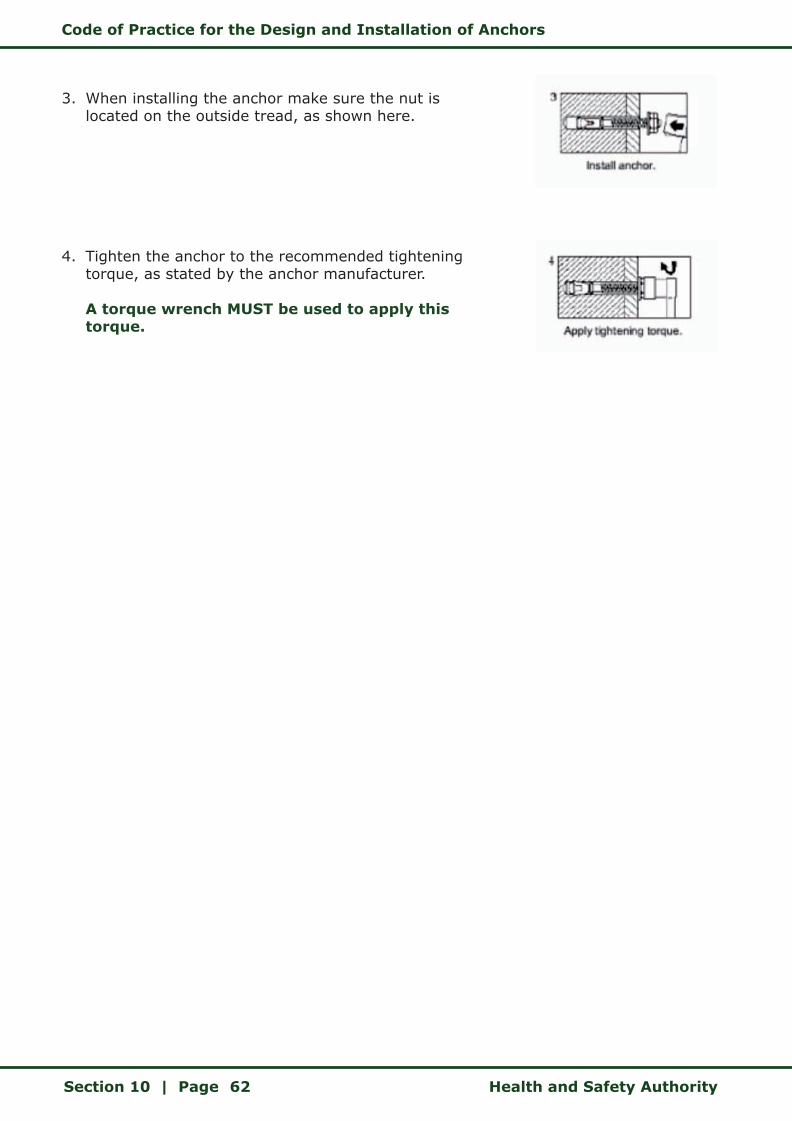
Code of Practice for the Design and Installation of Anchors
Section 10 | Page Health and Safety Authority62
3. When installing the anchor make sure the nut is located on the outside tread, as shown here.
4. Tighten the anchor to the recommended tightening torque, as stated by the anchor manufacturer. A torque wrench MUST be used to apply this torque.
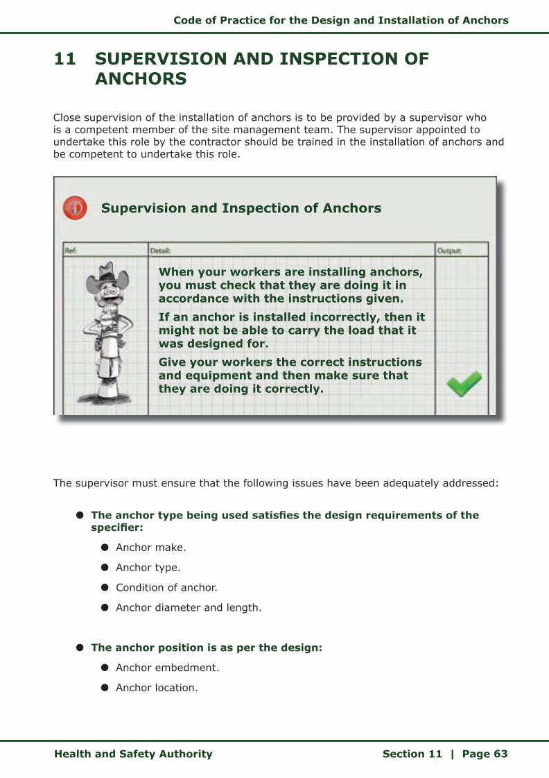
Code of Practice for the Design and Installation of Anchors
Health and Safety Authority Section 11 | Page 63
11 SUPERVISION AND INSPECTION OF ANCHORS
Close supervision of the installation of anchors is to be provided by a supervisor who is a competent member of the site management team. The supervisor appointed to undertake this role by the contractor should be trained in the installation of anchors and be competent to undertake this role.
The supervisor must ensure that the following issues have been adequately addressed:
z The anchor type being used satisfies the design requirements of the specifier:
z Anchor make.
z Anchor type.
z Condition of anchor.
z Anchor diameter and length.
z The anchor position is as per the design:
z Anchor embedment.
z Anchor location.
Supervision and Inspection of Anchors
When your workers are installing anchors, you must check that they are doing it in accordance with the instructions given.
If an anchor is installed incorrectly, then it might not be able to carry the load that it was designed for.
Give your workers the correct instructions and equipment and then make sure that they are doing it correctly.

Code of Practice for the Design and Installation of Anchors
Section 11 | Page Health and Safety Authority64
z The base material condition and hole dimensions are as specified:
z Concrete strength.
z Anchor hole diameters and depths as per the manufacturer’s recommendations.
z Setting out of anchors on the base material as per design, including factors that affect the capacity of the anchor such as required minimum thickness of base material, minimum edge distances and minimum spacing between the anchors.
z Condition of unit to be fixed:
z Fixture condition.
z Fixture type and material.
z Hole locations and diameters as per design.
z Installed anchor:
z Correct torque.
z Change of requirements:
z If amendments are required – due to reinforcement clash, quality of concrete base material etc. – the proposed revised installation must be communicated to the anchor specifier for approval.
The supervisor shall be required to certify that the anchor is correctly installed and suitable for loading. This acceptance shall be recorded by completion of form Anchor/FM-03 in Appendix A.
The supervision of the installation of the anchor is required to ensure that it is installed in accordance with:
z The design.
z The manufacturer’s recommendations.
In the event that the anchor hole clashes with reinforcement or other changes arise, the supervisor should give clear instructions to the anchor installer for the correct installation of the anchor. In this instance the anchor specifier must be made aware of and approve the proposed changes prior to the anchors being installed on site. ETAG 001, Annex C: Design methods for anchorages, gives guidance on the effects of reinforcement on the anchor design.
Changes in the specification of the proprietary anchors should only be made where the proposed alternative satisfies all the original design parameters and has been approved by the anchor specifier. Proprietary anchors should never be adapted or altered.
Once the installation of the anchor has been completed, and prior to the anchor being
Code of Practice for the Design and Installation of Anchors
Health and Safety Authority Section 11 | Page 65
subjected to the intended design loading a thorough inspection shall be undertaken. The supervisor shall inspect the fixture and each anchor prior to and subsequent to the load being fully transmitted into them.
Any observations regarding movements, cracking, rotation etc. should be carefully recorded and communicated to the PSCS and the anchor specifier. If the supervisor has any concerns regarding the suitability of the anchor, the placing of further units should not proceed and the anchor in question should be made safe until the concerns have been addressed to the satisfaction of the PSCS and the anchor specifier.
A similar inspection should be undertaken at each stage of subsequent loading.
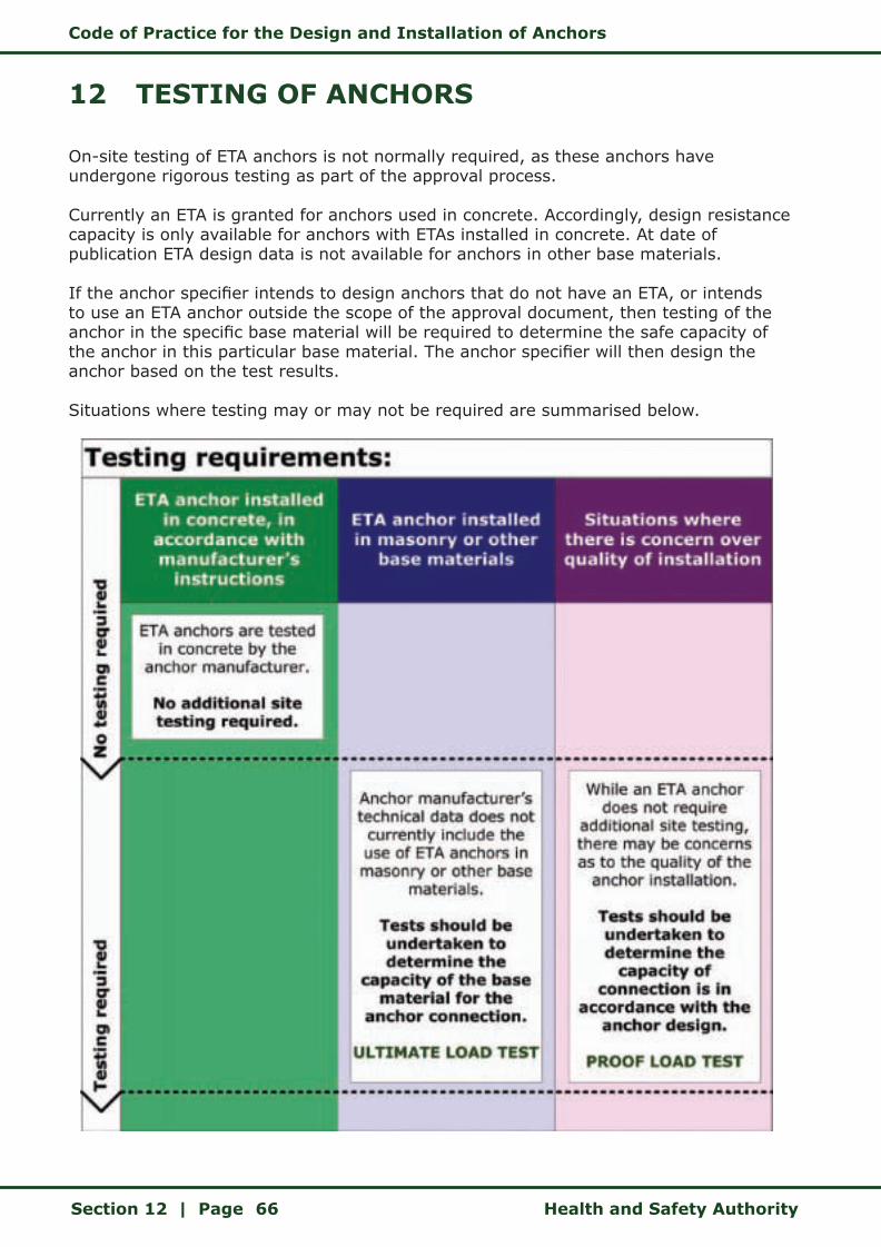
Code of Practice for the Design and Installation of Anchors
Section 12 | Page Health and Safety Authority66
12 TESTING OF ANCHORS
On-site testing of ETA anchors is not normally required, as these anchors have undergone rigorous testing as part of the approval process.
Currently an ETA is granted for anchors used in concrete. Accordingly, design resistance capacity is only available for anchors with ETAs installed in concrete. At date of publication ETA design data is not available for anchors in other base materials.
If the anchor specifier intends to design anchors that do not have an ETA, or intends to use an ETA anchor outside the scope of the approval document, then testing of the anchor in the specific base material will be required to determine the safe capacity of the anchor in this particular base material. The anchor specifier will then design the anchor based on the test results.
Situations where testing may or may not be required are summarised below.

Code of Practice for the Design and Installation of Anchors
Health and Safety Authority Section 12 | Page 67
Where tests are required, the requirements and objectives of the testing should be determined in advance. This will include the following considerations:
z Type and condition of base material.
z Anchor type.
z Installation details.
z Edge distances and spacing.
z Load direction (generally tensile tests are undertaken).
z Level of testing (ultimate load test or proof load test), refer to the anchor manufacturer.
z Competency of the anchor tester.
z Condition and calibration of the test equipment.
z Format and contents of the test report.
If undertaking tests to determine the capacity of a base material (ultimate load tests), at least three tests should be carried out.
Tests to verify the quality of the anchor installation (proof load tests) should include 2.5 percent of the total number of anchors installed (1 in 40 anchors), with a minimum of three tests. The rate of testing should be increased if anchors fail to achieve the criteria established by the anchor specifier.
Refer to the anchor manufacturer/supplier for further information and site-specific guidance.

Code of Practice for the Design and Installation of Anchors
Section 13 | Page Health and Safety Authority68
13 CERTIFICATION OF DESIGN AND INSTALLATION
In order to establish a formal record that the anchor system has been designed and installed to the approval of the anchor specifier, contractor, PSDP and PSCS, it is necessary to develop a system of certification. The certification system developed for use in conjunction with this code of practice also establishes lines of communication between the different parties involved.
Anchor specifiers should use form Anchor/FM-02 to record the design of temporary and permanent anchors so that the design assumptions for anchors can be clearly communicated. This record will assist the contractor to coordinate the checking of the anchor installations on site. A design risk assessment should be produced by the anchor specifier for the use of anchors for each particular application.
The anchor specifier and PSDP should complete either a permanent works design certificate (for permanent anchors) or a temporary works design certificate (for temporary anchors). While the use of the suggested Health and Safety Authority (HSA) certificates is not mandatory, it is anticipated that the anchor specifier and PSDP would use these or an equivalent alternative so as to communicate their compliance with health and safety legislation. Refer to the HSA’s Guidelines on the Procurement, Design and Management Requirements of the Safety, Health and Welfare at Work (Construction) Regulations 2006 for further information on permanent and temporary works design certificates.
As the installation process moves forward the contractor will arrange for the completion of the anchor installation checklist (form Anchor/FM-03) by the installation supervisor.
If amendments and redesign are required at any point during the design process or during the installation of the anchor, the PSDP will coordinate the activities of the designers (including the anchor specifier) and arrange for recertification as necessary.
The PSDP will liaise with the PSCS to ensure effective transfer of information from the anchor specifier to the contractor and to incorporate any amendments of the Safety and Health Plan into the Safety File.
On completion of the project the PSDP shall deliver the completed Safety File to the client, for his or her retention.
Code of Practice for the Design and Installation of Anchors
Health and Safety Authority Section 14 | Page 69
14 CHANGE MANAGEMENT — ALTERNATIVE ANCHORS
Change is an inevitable and continual process in the construction industry. Designs change when additional or new information becomes available. Proposed construction sequences and approaches can change when projects are awarded, as contractors seek to amend the materials and design used to suit their preferred method of working.
The person instigating the change is considered to be a designer and should comply with the requirements of this code of practice.
The successful management of change in the design and construction process requires that procedures be established which clearly define lines of communication and responsibilities. The flowcharts in Section 8 establish the various roles and responsibilities in the context of the scope of this code of practice.
The breakdown of communication and control systems can lead to significant changes taking place in the design assumptions or installation procedures without the knowledge of the anchor specifier. Un–communicated and/or un–documented changes can have serious consequences.
If changes are required to any element of the anchor design and/or installation, then they should be recorded on the design certificate and a full assessment of the changes should be completed by the anchor specifier. This process has to be coordinated by the PSDP.
Some typical changes that may occur are:
z Unavailability of or delay in sourcing the specified anchor leading to alternatives being used.
z Clashing with steel reinforcement leading to anchor holes being too short or in the wrong position.
z A late change in the design loading information leading to under-specified anchors.
Irrespective of the cause of the change, the anchor specifier has to re–design the anchor so as to ensure that the proposed anchor satisfies the original design assumptions and will have adequate capacity to support the loads imposed.
Form Anchor/FM-02 in Appendix A can be used to communicate the revised anchor specification. The anchor specifier can also issue hand calculations or the computer printout for the alternative anchor.

Code of Practice for the Design and Installation of Anchors
Appendix A | Page Health and Safety Authority70
Appendices
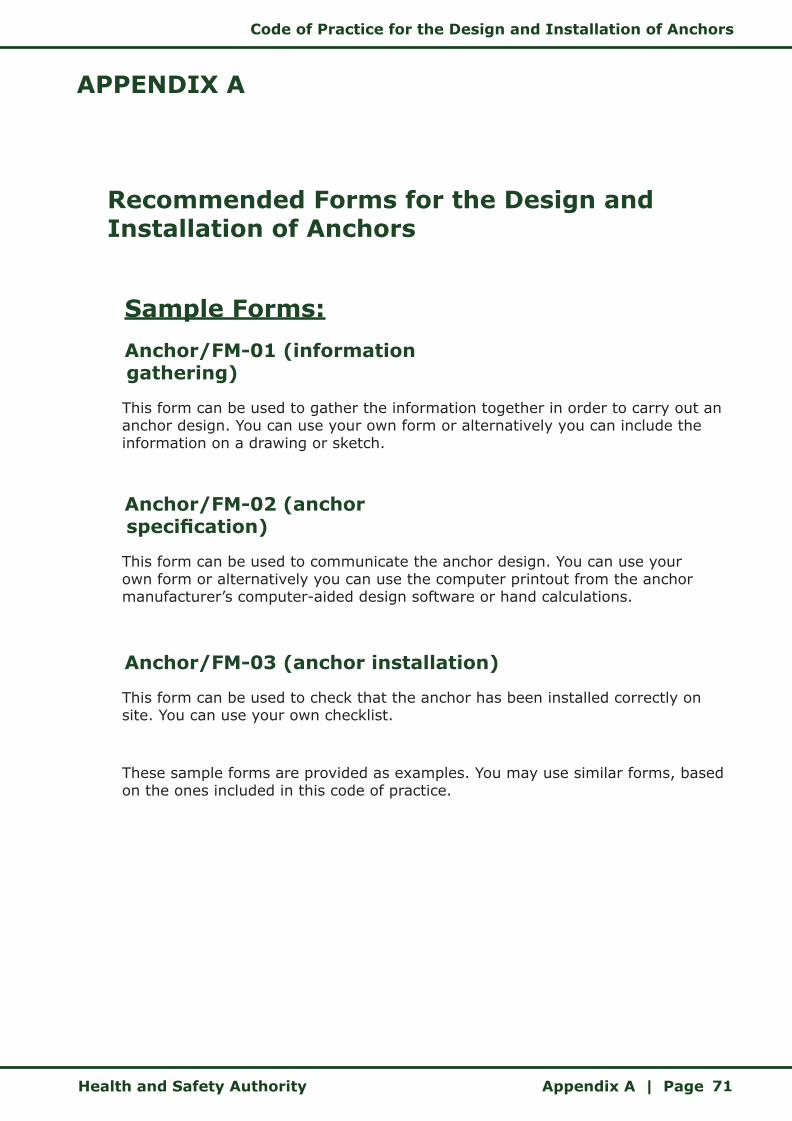
Code of Practice for the Design and Installation of Anchors
Health and Safety Authority Appendix A | Page 71
APPENDIX A
Recommended Forms for the Design and Installation of Anchors
Sample Forms:
Anchor/FM-01 (information gathering)
This form can be used to gather the information together in order to carry out an anchor design. You can use your own form or alternatively you can include the information on a drawing or sketch.
Anchor/FM-02 (anchor specification)
This form can be used to communicate the anchor design. You can use your own form or alternatively you can use the computer printout from the anchor manufacturer’s computer-aided design software or hand calculations.
Anchor/FM-03 (anchor installation)
This form can be used to check that the anchor has been installed correctly on site. You can use your own checklist.
These sample forms are provided as examples. You may use similar forms, based on the ones included in this code of practice.

Code of Practice for the Design and Installation of Anchors
Appendix A | Page Health and Safety Authority72
Anchor/FM-01 (information gathering)
This form can be used to gather the information together in order to carry out an anchor design.
Designer
• The designer can use this form to gather the information that will be needed to undertake the design of the anchor.
• If the design is going to be undertaken by another person (for example the anchor supplier), then this form is useful to communicate the particular application.
• The designer can complete this form and either use it in-house or forward it to the anchor supplier.
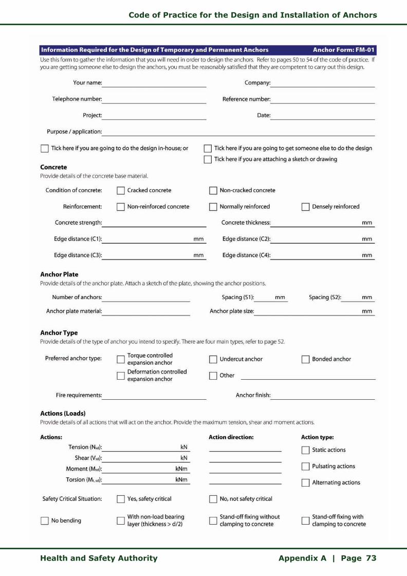
Code of Practice for the Design and Installation of Anchors
Health and Safety Authority Appendix A | Page 73
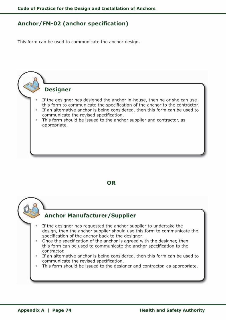
Code of Practice for the Design and Installation of Anchors
Appendix A | Page Health and Safety Authority74
Anchor/FM-02 (anchor specification)
This form can be used to communicate the anchor design.
OR
Designer
• If the designer has designed the anchor in-house, then he or she can use this form to communicate the specification of the anchor to the contractor.
• If an alternative anchor is being considered, then this form can be used to communicate the revised specification.
• This form should be issued to the anchor supplier and contractor, as appropriate.
Anchor Manufacturer/Supplier
• If the designer has requested the anchor supplier to undertake the design, then the anchor supplier should use this form to communicate the specification of the anchor back to the designer.
• Once the specification of the anchor is agreed with the designer, then this form can be used to communicate the anchor specification to the contractor.
• If an alternative anchor is being considered, then this form can be used to communicate the revised specification.
• This form should be issued to the designer and contractor, as appropriate.

Code of Practice for the Design and Installation of Anchors
Health and Safety Authority Appendix A | Page 75
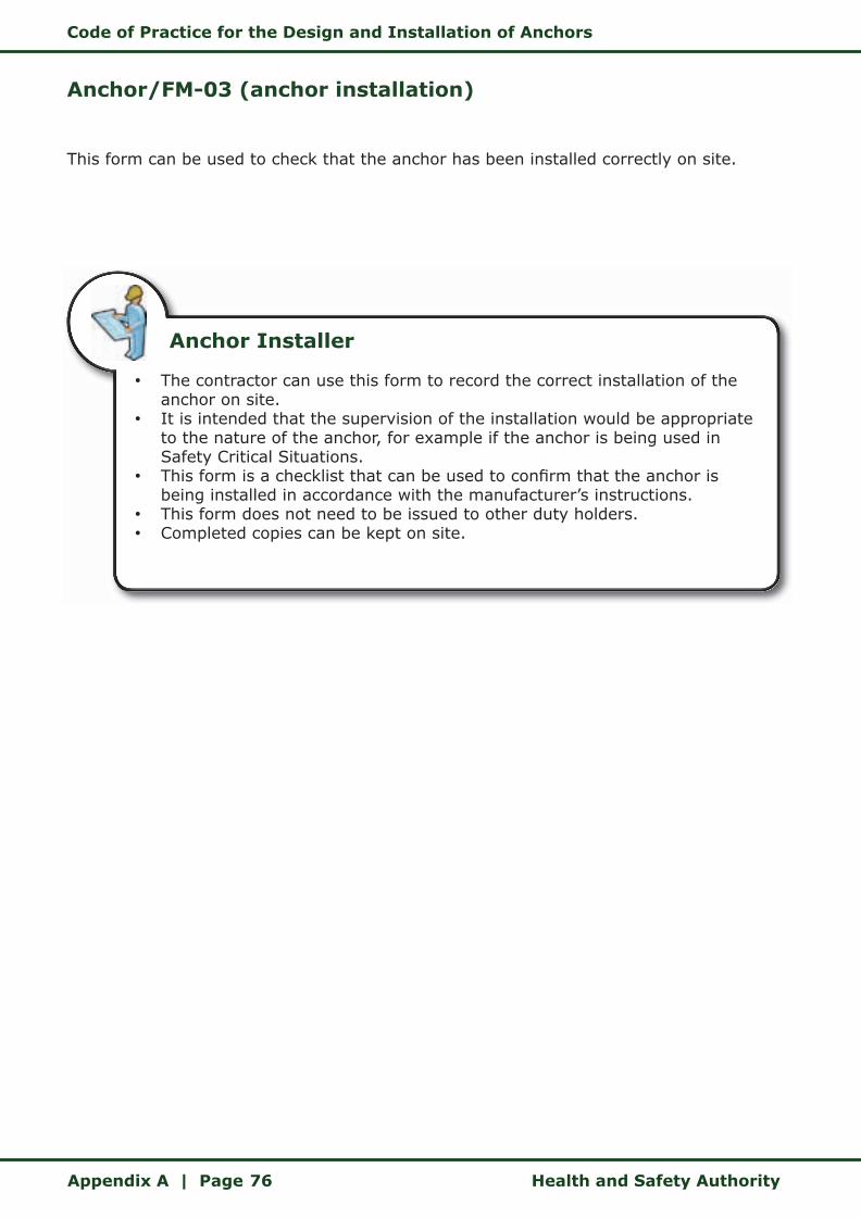
Code of Practice for the Design and Installation of Anchors
Appendix A | Page Health and Safety Authority76
Anchor/FM-03 (anchor installation)
This form can be used to check that the anchor has been installed correctly on site.
Anchor Installer
• The contractor can use this form to record the correct installation of the anchor on site.
• It is intended that the supervision of the installation would be appropriate to the nature of the anchor, for example if the anchor is being used in Safety Critical Situations.
• This form is a checklist that can be used to confirm that the anchor is being installed in accordance with the manufacturer’s instructions.
• This form does not need to be issued to other duty holders. • Completed copies can be kept on site.
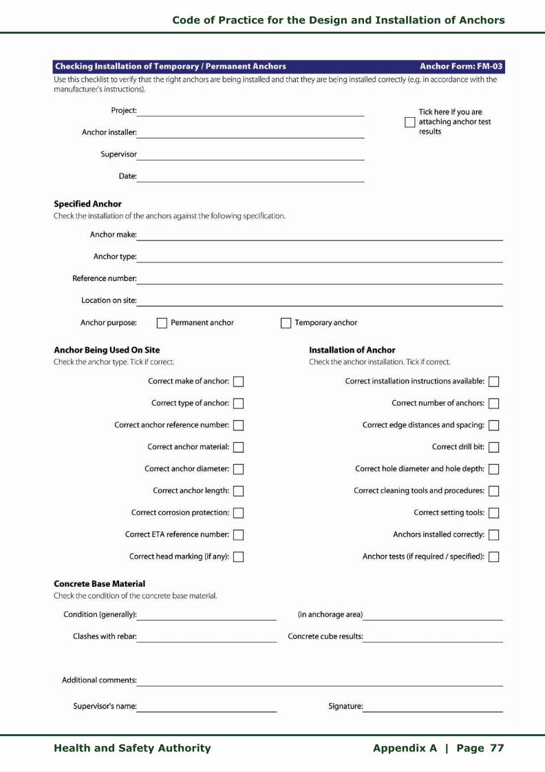
Code of Practice for the Design and Installation of Anchors
Health and Safety Authority Appendix A | Page 77

Code of Practice for the Design and Installation of Anchors
Appendix B | Page Health and Safety Authority78
APPENDIX B
Example of
European Technical Approval Document
(ETA 05/0789)
ETA 05/0789 is a fictitious reference number and does not relate to an actual ETA.
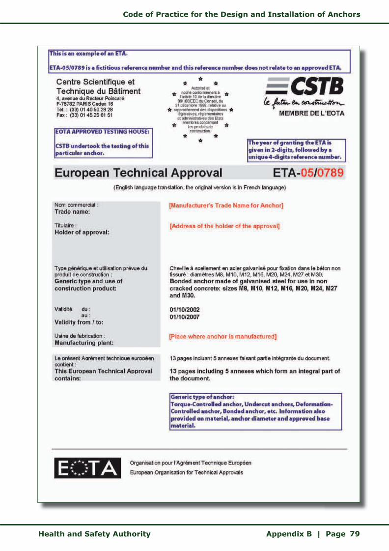
Code of Practice for the Design and Installation of Anchors
Health and Safety Authority Appendix B | Page 79

Code of Practice for the Design and Installation of Anchors
Appendix B | Page Health and Safety Authority80
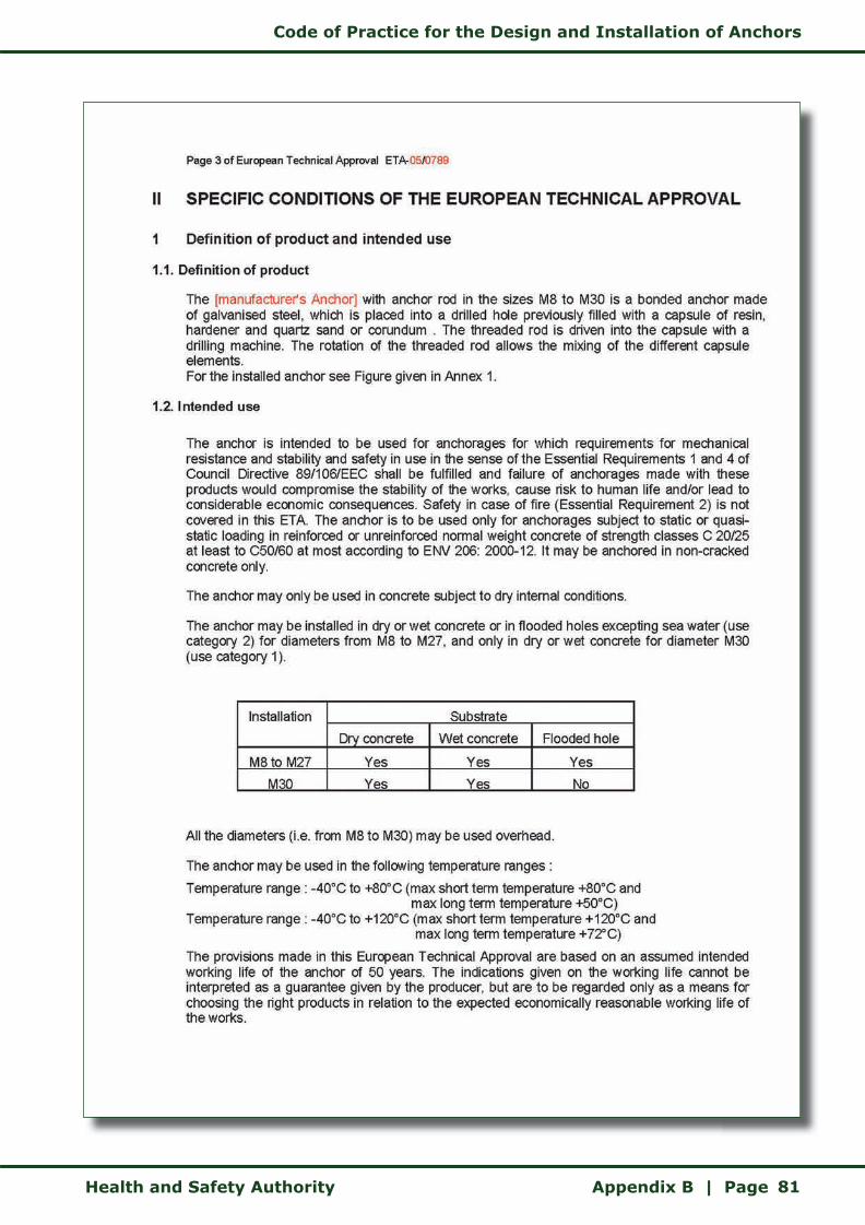
Code of Practice for the Design and Installation of Anchors
Health and Safety Authority Appendix B | Page 81

Code of Practice for the Design and Installation of Anchors
Appendix B | Page Health and Safety Authority82
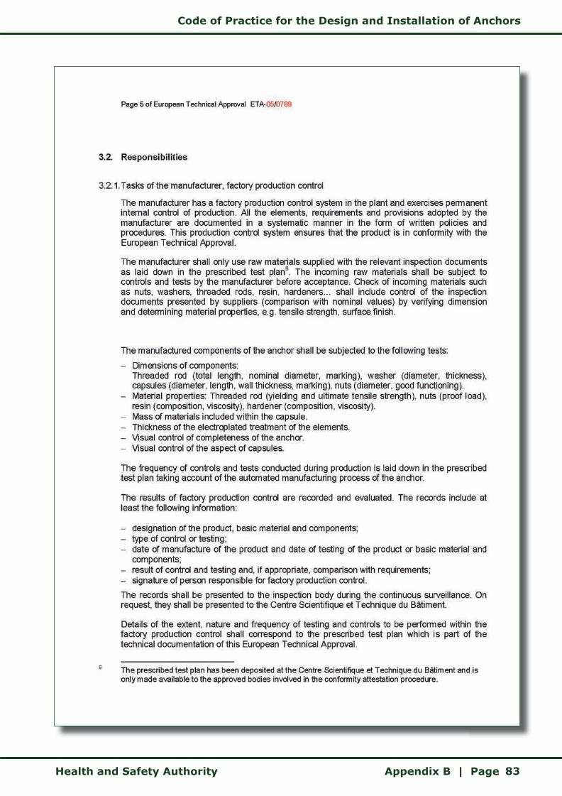
Code of Practice for the Design and Installation of Anchors
Health and Safety Authority Appendix B | Page 83

Code of Practice for the Design and Installation of Anchors
Appendix B | Page Health and Safety Authority84
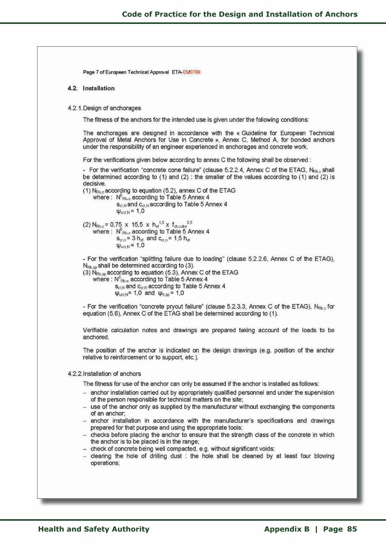
Code of Practice for the Design and Installation of Anchors
Health and Safety Authority Appendix B | Page 85

Code of Practice for the Design and Installation of Anchors
Appendix B | Page Health and Safety Authority86
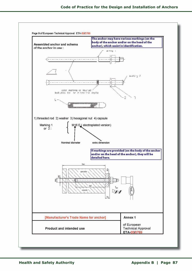
Code of Practice for the Design and Installation of Anchors
Health and Safety Authority Appendix B | Page 87

Code of Practice for the Design and Installation of Anchors
Appendix B | Page Health and Safety Authority88
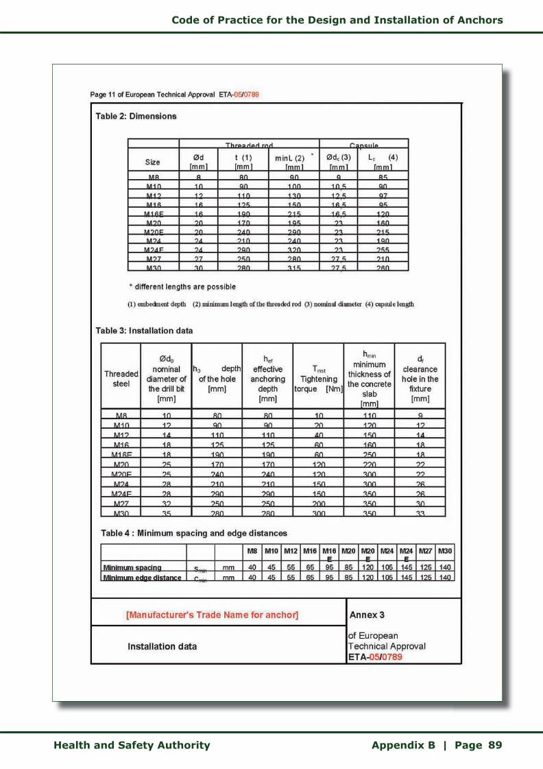
Code of Practice for the Design and Installation of Anchors
Health and Safety Authority Appendix B | Page 89
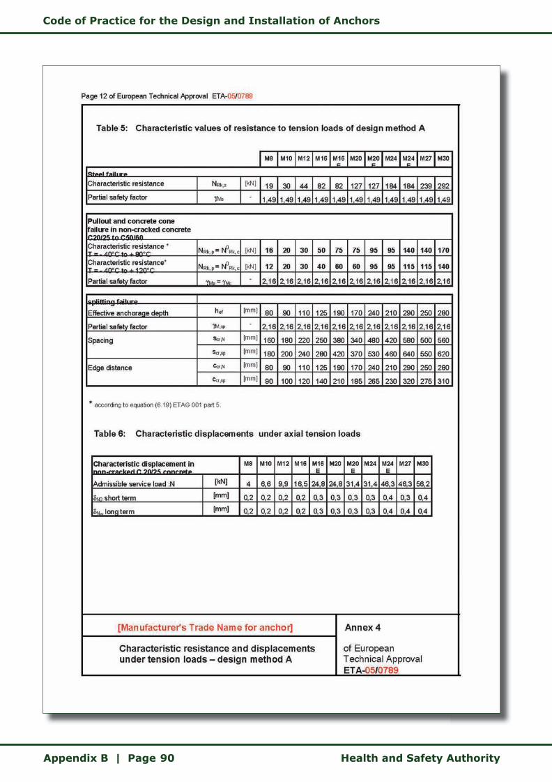
Code of Practice for the Design and Installation of Anchors
Appendix B | Page Health and Safety Authority90
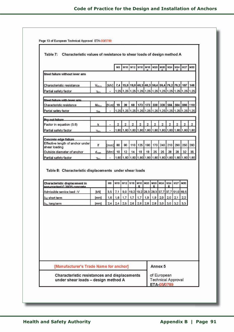
Code of Practice for the Design and Installation of Anchors
Health and Safety Authority Appendix B | Page 91
Code of Practice for the Design and Installation of Anchors
Appendix C | Page Health and Safety Authority92
APPENDIX C
Information Sources

Code of Practice for the Design and Installation of Anchors
Health and Safety Authority Appendix C | Page 93
Statutory Provisionswww.irishstatutebook.ie
Safety, Health and Welfare at Work Act 2005 (No. 10 of 2005)
Safety, Health and Welfare at Work (General Application) Regulations 2007(S.I. No. 299 of 2007)
Safety, Health and Welfare at Work (General Application)(Amendment) Regulations 2007(S.I. No. 732 of 2007)
Safety, Health and Welfare at Work (Construction) Regulations 2006(S.I. No. 504 of 2006)
Safety, Health and Welfare at Work (Construction)(Amendment) Regulations 2008(S.I. No. 130 of 2008)
Safety, Health and Welfare at Work (Construction)(Amendment)(No 2) Regulations 2008(S.I. No. 423 of 2008)
European Communities (Construction Products) Regulations 1992 (S.I. No. 198 of 1992)
European Communities (Construction Products)(Amendment) Regulations 1994 (S.I. No. 210 of 1994)
Irish Standards, British Standards, Codes and Other Standardswww.nsai.ie
I.S. EN 206-1: 2002 Concrete. Specification, performance, production and conformity
BS EN ISO 898-1: 1999 Mechanical properties of fasteners made of carbon steel and alloy steel — Part 1: Bolts, screws and studs
BS 5080-1: 1993 Structural fixings in concrete and masonry — Part 1: Method of test for tensile loading
BS 5080-2: 1986 Methods of test for structural fixings in concrete and masonry — Part 2: Method for determination of resistance to loading in shear
BS 8110-1: 1997 Structural use of concrete
EN 1990: 2002 Basis of design for structural Eurocodes
EN 1992-1-1: 2003 Eurocode 2: Design of concrete structures - Part 1-1 : General common rules and rules for building and civil engineering structures
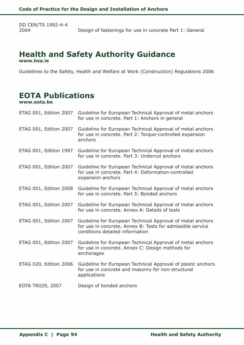
Code of Practice for the Design and Installation of Anchors
Appendix C | Page Health and Safety Authority94
DD CEN/TS 1992-4-4 2004 Design of fastenings for use in concrete Part 1: General
Health and Safety Authority Guidancewww.hsa.ie
Guidelines to the Safety, Health and Welfare at Work (Construction) Regulations 2006
EOTA Publicationswww.eota.be
ETAG 001, Edition 2007 Guideline for European Technical Approval of metal anchors for use in concrete. Part 1: Anchors in general
ETAG 001, Edition 2007 Guideline for European Technical Approval of metal anchors for use in concrete. Part 2: Torque-controlled expansion anchors
ETAG 001, Edition 1997 Guideline for European Technical Approval of metal anchors for use in concrete. Part 3: Undercut anchors
ETAG 001, Edition 2007 Guideline for European Technical Approval of metal anchors for use in concrete. Part 4: Deformation-controlled expansion anchors
ETAG 001, Edition 2008 Guideline for European Technical Approval of metal anchors for use in concrete. Part 5: Bonded anchors
ETAG 001, Edition 2007 Guideline for European Technical Approval of metal anchors for use in concrete. Annex A: Details of tests
ETAG 001, Edition 2007 Guideline for European Technical Approval of metal anchors for use in concrete. Annex B: Tests for admissible service conditions detailed information
ETAG 001, Edition 2007 Guideline for European Technical Approval of metal anchors for use in concrete. Annex C: Design methods for anchorages
ETAG 020, Edition 2006 Guideline for European Technical Approval of plastic anchors for use in concrete and masonry for non-structural applications
EOTA TR029, 2007 Design of bonded anchors
Code of Practice for the Design and Installation of Anchors
Health and Safety Authority Appendix C | Page 95
General Guideline 89/106/EWG of the Council of 21 December 1988 for harmonising the legal and administrative regulations for building products in the member countries, modified by guideline 93/68/EWG of 22 July 1993, Gazette of the European Community |No. L 40 of 11 February 1989 and L 220 of 30 August 1993
Council Directive 89/106/EEC. Construction products. Interpretative documents, Brussels, 16 July 1993
R. Eligehausen, R. Mallée and J.F. Silva (2006) Anchorage in Concrete Construction
Construction Fixings Association’s series of guidance notes on anchor-related issues
Code of Practice for the Design and Installation of Anchors
Index | Page Health and Safety Authority96
INDEX
anchor ........................................... 13
anchor design ................................. 43
anchor installer 11, 13, 28, 29, 32, 33, 60, 64
anchor manufacturer ..................29, 56
anchor spacing ................................ 39
anchor specifier 11, 13, 26, 27, 29, 31, 35, 36, 37, 44, 45, 46, 57, 64, 66, 68, 69
anchor supplier ......... 11, 29, 31, 33, 35
anchor types ..............................23, 41
article ............................................ 13
base material .............................14, 36
bonded anchors ............................... 25
certification .................................... 68
clearance hole ................................. 54
client ............................................. 14
competent person ................. 14, 35, 60
computer-aided anchor design software 30, 46
concrete ......................................... 36
concrete capacity method 14, 16, 35 SEE ALSO PARTIAL SAFETY FACTOR
concrete strength ............................ 14
connection ...................................... 15
Construction Product Directive .......... 15
contractor ...........15, 29, 33, 60, 68, 69
corrosion protection ......................... 41
cracked concrete ............................. 36
deformation-controlled anchors ......... 24
design methods ............................... 35
design process ...........................11, 15
design resistance ........................16, 56
design risk assessment ...............16, 68
design change ................................. 69
edge distance ................................. 39
effective embedment depth .............. 40
EOTA ............................................. 17
essential requirements ................19, 21
ETA 4, 9, 17, 19, 21, 26, 29, 36, 37, 56, 57, 66
ETAG ............................................. 19
European Technical Approval ......... 4, 30
fixture .......................................17, 54
global safety factor ........... 9, 11, 10, 17
installation instructions .................... 30
load direction .................................. 37
load type ...................................37, 40
manufacturer’s instructions ............... 29
masonry ......................................... 37
material type .................................. 56
non-cracked concrete ....................... 36
partial safety factor ... 9, 10, 11, 18 SEE ALSO CONCRETE CAPACITY METHOD
permanent works design certificate .... 68
permanent works designer ................ 18
projection ....................................... 54
project supervisor construction stage 18, 29, 34
project supervisor design process 18, 29, 33

Code of Practice for the Design and Installation of Anchors
Health and Safety Authority Index | Page 97
recommended load .......................... 16
safety critical situation ................. 4, 18
safety data sheets ......................30, 56
Safety, Health and Welfare at Work (Construction) Regulations 2006 .... 3, 29
sample forms .................................. 70
supervision ..................................... 63
supervisor ........................... 63, 64, 68
technical data sheets ....................... 30
temporary works ............................. 18
temporary works design certificate ..... 68
torque-controlled expansion anchor ... 23
training .......................................... 35
types of anchors .............................. 13
undercut anchors ............................ 24

ISBN No: 978-1-84496-126-5 HSA0333