
Installation and Technical Manual - Aquatic Specialty Services · 2011-02-07 · Installation and...
25
9487 Dielman Rock Island Industrial Dr. St. Louis, MO 63132 Tel:(314) 567-0088 Installation and Technical Manual Rev: D08.1 Installation and Technical Manual
Transcript of Installation and Technical Manual - Aquatic Specialty Services · 2011-02-07 · Installation and...
9487 Dielman Rock Island Industrial Dr. St. Louis, MO 63132 Tel:(314) 567-0088
Installation and Technical Manual Rev: D08.1
Installation and Technical Manual

9487 Dielman Rock Island Industrial Dr. St. Louis, MO 63132 Tel:(314) 567-0088
Installation and Technical Manual Rev: D08.1
TABLE OF CONTENTS
Unpacking........................................................................... 1 General Guidelines ............................................................. 1 Firmware Version ............................................................... 1 Environmental Conditions .................................................. 2 Electrical Specifications...................................................... 2 Warnings............................................................................. 3 Section A: Mounting the BECSys2 Controller .................. 4
A – 1: Mounting the Controller...................................... 4 A – 2: Wrapping the Fittings.......................................... 4 A – 3: Assembling the Flow cell.................................... 4 A – 4: ORP and pH Sensor preparations........................ 4 A – 5: Plumbing the Sample Stream.............................. 4 A – 6: Opening the Sample Stream Valve ..................... 4
Section B: Wiring the BECSys2 Controller....................... 5 B – 1: Wiring the Unit ................................................... 5 B – 2: Opening the Cover .............................................. 5 B – 3: Removing the Safety Shield................................ 5 B – 4: Disconnecting the Ribbon Cable......................... 6 B – 5: Wiring Directly to the Unit ................................. 6 B – 6: Wiring Power ...................................................... 6 B – 7: Wiring Relay 1 Directly ...................................... 6 B – 8: Wiring Relay 2 Directly ...................................... 7 B – 9: Wiring Relay 3 Directly ...................................... 7 B – 10: Wiring a Flow Switch ....................................... 7
B – 10.1: Paddlewheel Flow Switch .......................... 8 B – 10.2: Reed Flow Switch ...................................... 8
B – 11: Wiring a Timer .................................................. 8 B – 12: Fuses.................................................................. 8
Section C: Dip Switch Settings.......................................... 9 C – 1: Choosing pH Feed Direction............................... 9 C – 2: Choosing On/Off Control or TBP ....................... 9 C – 3: Setting the Failsafe Timer Settings ..................... 9 C – 4: Relay 3 Functions.............................................. 10
C – 4.1: Sensor Wash............................................... 10 C – 4.2: Dual pH Control ......................................... 10 C – 4.3: Alarm Relay ............................................... 10 C – 4.4: Cl/Br Booster ............................................. 10
C – 5: Replacing the Cover .......................................... 10 Section D: Programming the Controller .......................... 11
D – 1: The Program Menu ........................................... 11 D – 1.1: Entering the Program Menu ....................... 11 D – 1.2: Selecting Language .................................... 11 D – 1.3: pH High Alarm Point ................................. 11 D – 1.4: pH Low Alarm Point.................................. 11 D – 1.5: ORP High Alarm Point .............................. 11 D – 1.6: ORP Low Alarm Point ............................... 11 D – 1.7: ORP/ppm.................................................... 11 D – 1.8: Exiting the Menu........................................ 11
D – 2: The System Settings Menu ............................... 12 D – 2.1: Entering the System Settings Menu ........... 12 D – 2.2: Setting the ORP Span................................. 12 D – 2.3: Setting the pH Span.................................... 12
D – 2.4: Setting the Time Base.................................12 D – 2.5: Performing a two-point pH Cal. .................12 D – 2.6: Performing a two-point ORP Cal. ..............12 D – 2.7: Flow disruption feed delay .........................12 D – 2.9: ppm Control................................................13 D – 2.10: Booster Failsafe ........................................13 D – 2.11: pH Dead Zone ..........................................13 D – 2.12: Relay Test.................................................13 D – 2.13: Exiting the System Settings Menu............13
Section E: Normal Operation ...........................................14 E – 1: Displaying the Set points ...................................14 E – 2: Modifying the Set Points ...................................14
E – 2.1: Modifying the pH Set Point ........................14 E – 2.2: Modifying the ORP Set Point .....................14 E – 2.3: Modifying the ppm Set Point ......................14 E – 2.4: Modifying the Booster Trigger Point..........14 E – 2.5: Modifying the Booster End Point ...............14
E – 3: Single Point Calibration.....................................14 E – 3.1: Single Point Calibration - pH......................14 E – 3.2: Single Point Calibration - ppm....................14 E – 3.3: Probe Error..................................................15
E – 4: Alarms................................................................15 E – 4.1: pH High/Low alarms...................................15 E – 4.2: ORP High/Low alarms................................15 E – 4.4: No Flow alarm ............................................15 E – 4.5: (x) min Feed Delay .....................................15 E – 4.6: Cl/Br Lockout .............................................15 E – 4.7: pH FAILSAFE ALM ..................................15 E – 4.8: Cl/Br FAILSAFE........................................15 E – 4.9: Booster FAILSAFE ....................................15
E – 5: Resetting a Failsafe Alarm.................................15 Section F: Maintenance ....................................................16
F – 1: Potentiometric Sensors (pH and ORP)...............16 F – 1.1: Electrode Cleaning:.....................................16 F – 1.2: Long-Term Storage: ....................................16
Section G: Feed Charts.....................................................17 G – 1: Spa Feed Charts.................................................17 G – 2: Pool Feed Charts ...............................................18
Section H: Installation Diagrams......................................19 H – 1: Pressure Filter Installation.................................19 H – 2: Vacuum Filter Installation.................................19
Section I: Warranty ..........................................................20

Page 1 9487 Dielman Rock Island Industrial Dr. St. Louis, MO 63132 Tel:(314) 567-0088
Installation and Technical Manual Rev: D08.1D08.1
Unpacking Unpacking
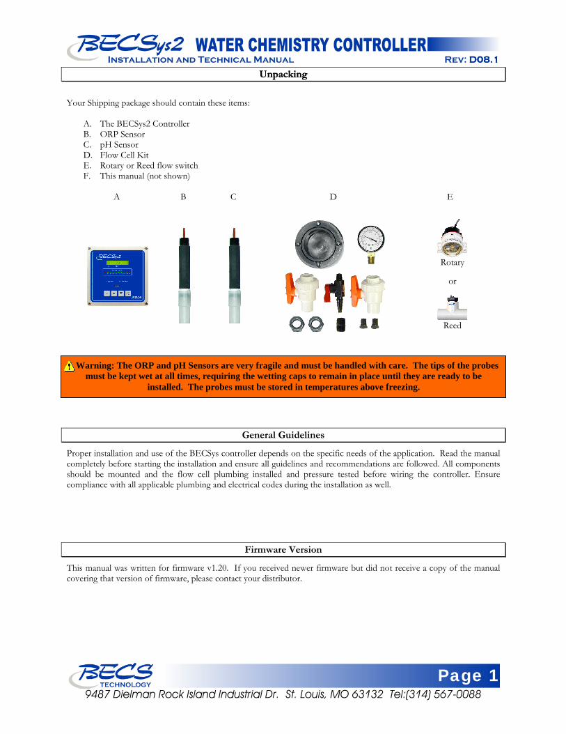
Your Shipping package should contain these items: A. The BECSys2 Controller B. ORP Sensor C. pH Sensor D. Flow Cell Kit E. Rotary or Reed flow switch F. This manual (not shown) A B C D E
Rotary
Reed
or
Warning: The ORP and pH Sensors are very fragile and must be handled with care. The tips of the probes must be kept wet at all times, requiring the wetting caps to remain in place until they are ready to be
installed. The probes must be stored in temperatures above freezing.
General Guidelines
Proper installation and use of the BECSys controller depends on the specific needs of the application. Read the manual completely before starting the installation and ensure all guidelines and recommendations are followed. All components should be mounted and the flow cell plumbing installed and pressure tested before wiring the controller. Ensure compliance with all applicable plumbing and electrical codes during the installation as well.
Firmware Version
This manual was written for firmware v1.20. If you received newer firmware but did not receive a copy of the manual covering that version of firmware, please contact your distributor.
Page 2 9487 Dielman Rock Island Industrial Dr. St. Louis, MO 63132 Tel:(314) 567-0088
Installation and Technical Manual Rev: D08.1
Environmental Conditions
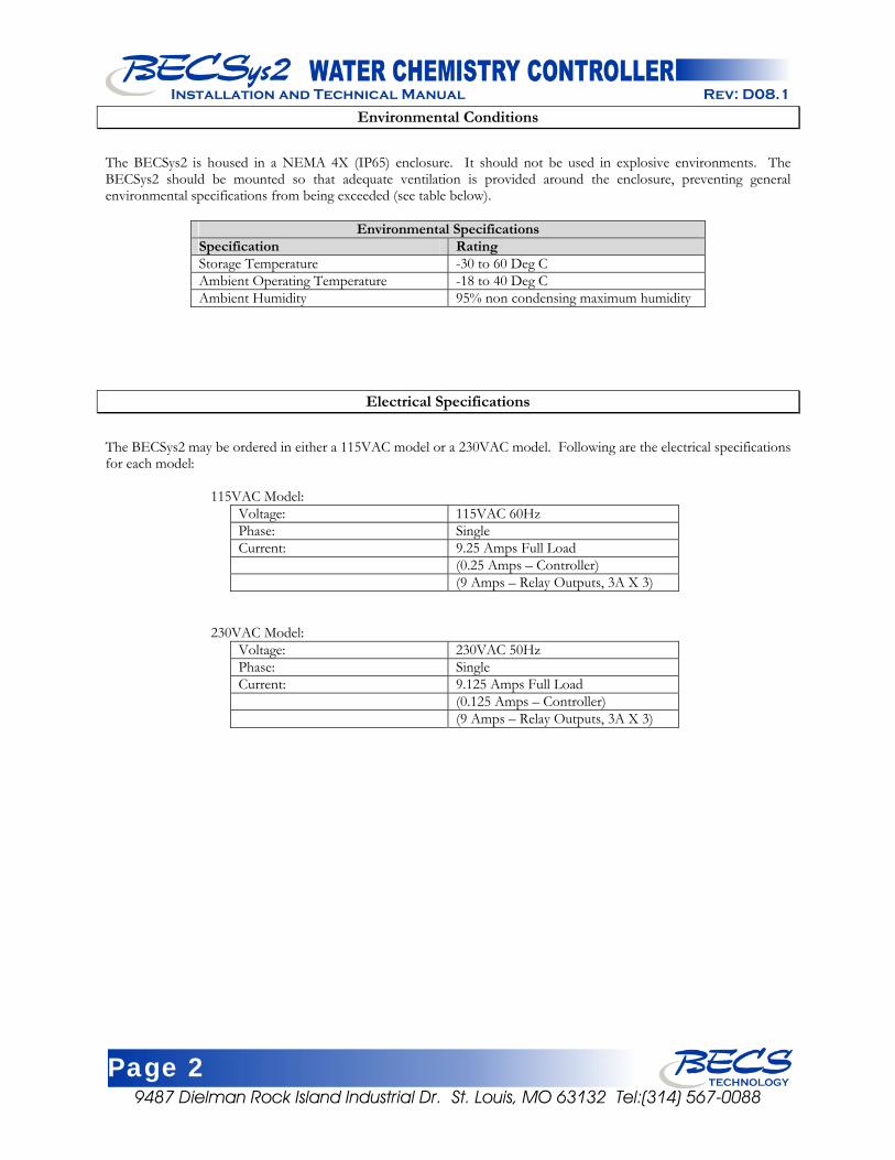
The BECSys2 is housed in a NEMA 4X (IP65) enclosure. It should not be used in explosive environments. The BECSys2 should be mounted so that adequate ventilation is provided around the enclosure, preventing general environmental specifications from being exceeded (see table below).
Environmental Specifications Specification Rating Storage Temperature -30 to 60 Deg C Ambient Operating Temperature -18 to 40 Deg C Ambient Humidity 95% non condensing maximum humidity
Electrical Specifications
The BECSys2 may be ordered in either a 115VAC model or a 230VAC model. Following are the electrical specifications for each model:
115VAC Model: Voltage: 115VAC 60Hz Phase: Single Current: 9.25 Amps Full Load (0.25 Amps – Controller) (9 Amps – Relay Outputs, 3A X 3)
230VAC Model: Voltage: 230VAC 50Hz Phase: Single Current: 9.125 Amps Full Load (0.125 Amps – Controller) (9 Amps – Relay Outputs, 3A X 3)
Page 3 9487 Dielman Rock Island Industrial Dr. St. Louis, MO 63132 Tel:(314) 567-0088
Installation and Technical Manual Rev: D08.1D08.1
Warnings Warnings
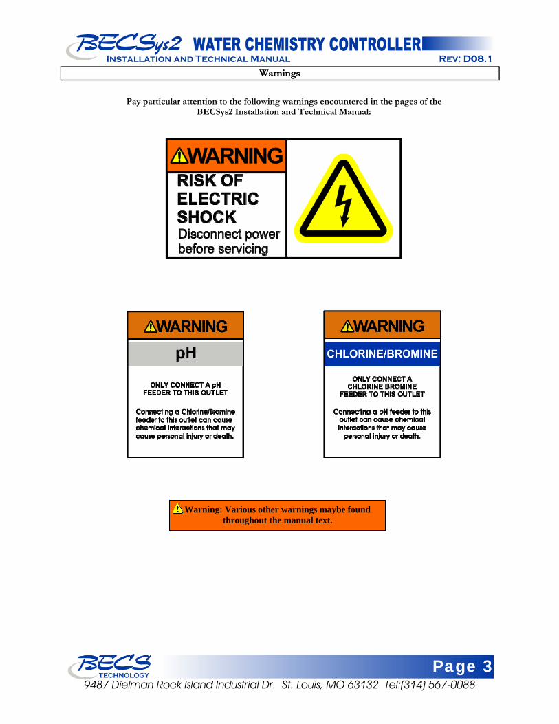
Pay particular attention to the following warnings encountered in the pages of the
BECSys2 Installation and Technical Manual:
Warning: Various other warnings maybe found throughout the manual text.
Page 4 9487 Dielman Rock Island Industrial Dr. St. Louis, MO 63132 Tel:(314) 567-0088
Installation and Technical Manual Rev: D08.1
Section A: Mounting the BECSys2 Controller
A – 1: Mounting the Controller The BECSys2 Controller and flow cell are mounted separately. The BECSys2 enclosure should be mounted to the wall with four anchor bolts, one installed in each corner of the enclosure base. To mount the BECSys2 properly, please use the included mounting template and hardware. Drill the holes for the anchors using a 3/16” drill bit. Install the anchors in the wall. Remove the lid from the unit and place the included screws in the four corners of the box. Attach the screws into the anchors. The BECSys2 and flow cell should be mounted in a location that is free from chemical fumes and excessive heat, isolated from electrical interference, and near a power source protected by a ground fault interrupter. The BECSys2 has a NEMA4 weather resistant enclosure but should still be protected if mounted outdoors.
A – 2: Wrapping the Fittings If you are assembling a flow cell, first open the bag of flow cell fittings and wrap each fitting two times around clockwise with Teflon tape.
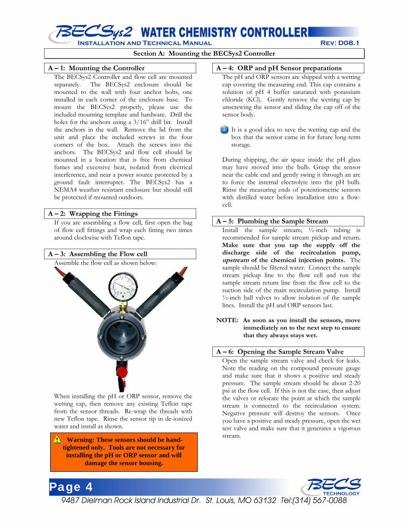
A – 3: Assembling the Flow cell Assemble the flow cell as shown below:
When installing the pH or ORP sensor, remove the wetting cap, then remove any existing Teflon tape from the sensor threads. Re-wrap the threads with new Teflon tape. Rinse the sensor tip in de-ionized water and install as shown.
A – 4: ORP and pH Sensor preparations The pH and ORP sensors are shipped with a wetting cap covering the measuring end. This cap contains a solution of pH 4 buffer saturated with potassium chloride (KCl). Gently remove the wetting cap by unscrewing the sensor and sliding the cap off of the sensor body.
It is a good idea to save the wetting cap and the box that the sensor came in for future long-term storage.
During shipping, the air space inside the pH glass may have moved into the bulb. Grasp the sensor near the cable end and gently swing it through an arc to force the internal electrolyte into the pH bulb. Rinse the measuring ends of potentiometric sensors with distilled water before installation into a flow-cell.
A – 5: Plumbing the Sample Stream Install the sample stream; ½-inch tubing is recommended for sample stream pickup and return. Make sure that you tap the supply off the discharge side of the recirculation pump, upstream of the chemical injection points. The sample should be filtered water. Connect the sample stream pickup line to the flow cell and run the sample stream return line from the flow cell to the suction side of the main recirculation pump. Install ½-inch ball valves to allow isolation of the sample lines. Install the pH and ORP sensors last.
NOTE: As soon as you install the sensors, move immediately on to the next step to ensure that they always stays wet.
A – 6: Opening the Sample Stream Valve
Open the sample stream valve and check for leaks. Note the reading on the compound pressure gauge and make sure that it shows a positive and steady pressure. The sample stream should be about 2-20 psi at the flow cell. If this is not the case, then adjust the valves or relocate the point at which the sample stream is connected to the recirculation system. Negative pressure will destroy the sensors. Once you have a positive and steady pressure, open the wet test valve and make sure that it generates a vigorous stream. Warning: These sensors should be hand-
tightened only. Tools are not necessary for installing the pH or ORP sensor and will
damage the sensor housing.
Page 5 9487 Dielman Rock Island Industrial Dr. St. Louis, MO 63132 Tel:(314) 567-0088
Installation and Technical Manual Rev: D08.1
Section B: Wiring the BECSys2 Controller
B – 1: Wiring the Unit
There are several ways that you can wire the relays and power to the unit. The easiest is to use the cords already installed in the unit. Plug the AC Cord into a GFCI outlet (only for low voltage 110VAC-120VAC applications) and connect the chemical feeders to the female power cords (pigtails). The pigtails are labeled with the below warning tags. Be sure to connect the correct pigtail to the correct chemical feeder. You must still remove the cover to install the Flow Switch.
The second way is to discard the pre-installed cords and wire the unit directly.
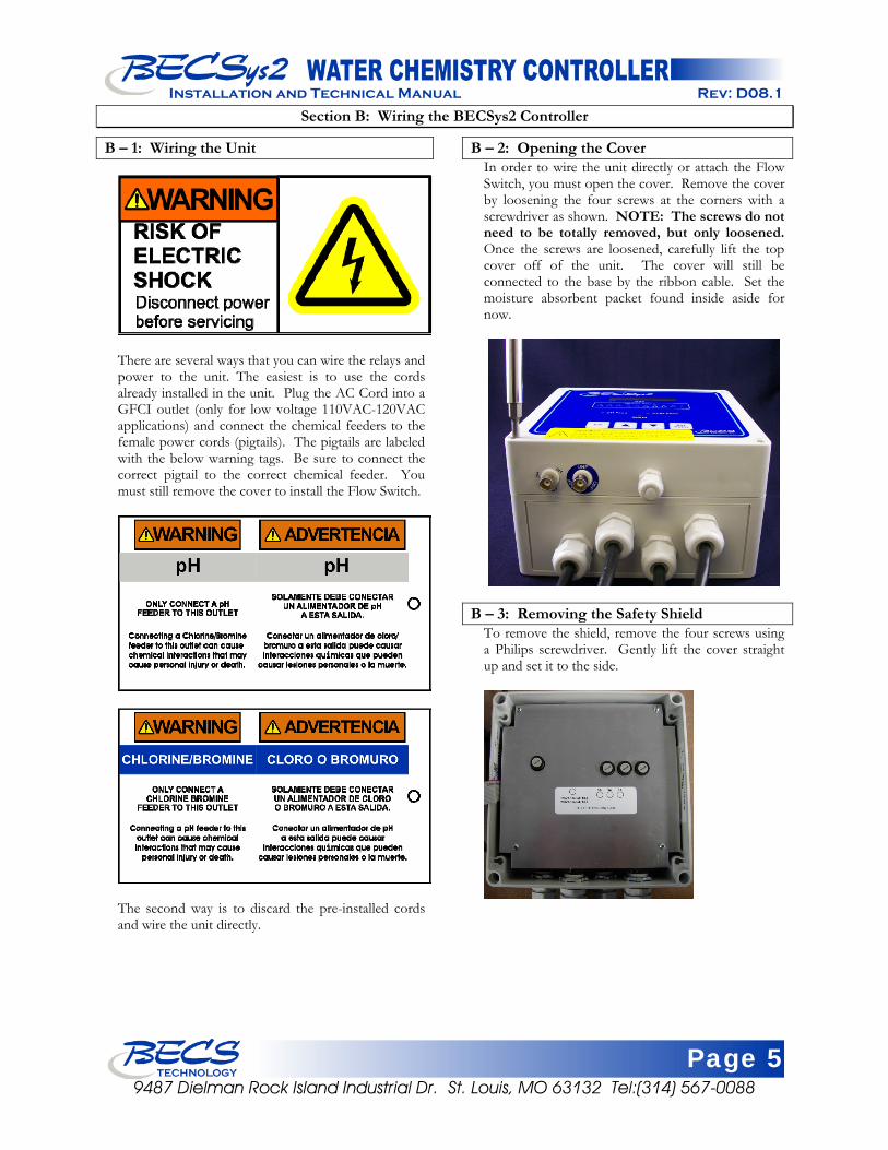
B – 2: Opening the Cover In order to wire the unit directly or attach the Flow Switch, you must open the cover. Remove the cover by loosening the four screws at the corners with a screwdriver as shown. NOTE: The screws do not need to be totally removed, but only loosened. Once the screws are loosened, carefully lift the top cover off of the unit. The cover will still be connected to the base by the ribbon cable. Set the moisture absorbent packet found inside aside for now.
B – 3: Removing the Safety Shield To remove the shield, remove the four screws using a Philips screwdriver. Gently lift the cover straight up and set it to the side.
Page 6 9487 Dielman Rock Island Industrial Dr. St. Louis, MO 63132 Tel:(314) 567-0088
Installation and Technical Manual Rev: D08.1
B – 4: Disconnecting the Ribbon Cable We recommend that you disconnect the ribbon cable by spreading the two holders at the end of the cable attached to the cover as shown, unplugging the cable and removing the cover.
NOTE: Be sure to store the cover in a safe, dry place while you wire and set up the unit.
B – 5: Wiring Directly to the Unit To wire the unit directly, you must remove the pigtails already installed. You may use the two ½-inch holes in the casing to enable you to easily run wires to Terminal Block 1 inside the base of the unit.
NOTE: There are Terminal Blocks labeled TB1 and TB2 in both the cover and base of the unit and they serve different functions.
Use the ½-inch cord grips provided and whatever holes are convenient, but when you are all finished wiring the unit, be sure to plug any unused holes with a ½-inch NEMA 4x plug.
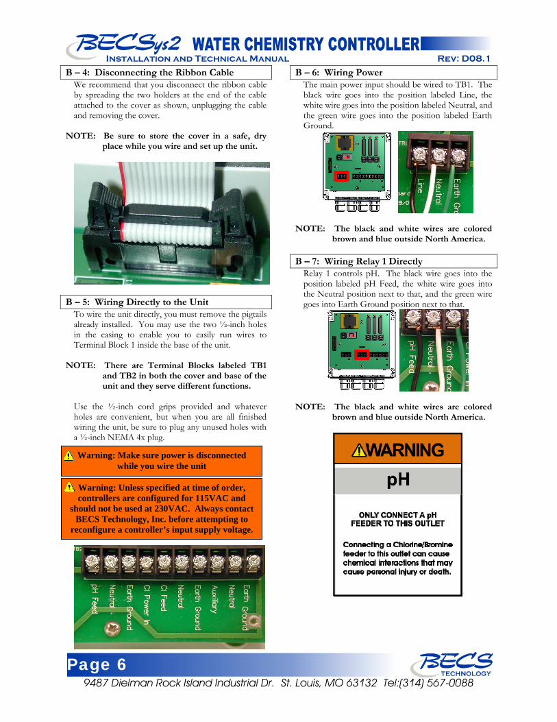
B – 6: Wiring Power The main power input should be wired to TB1. The black wire goes into the position labeled Line, the white wire goes into the position labeled Neutral, and the green wire goes into the position labeled Earth Ground.
NOTE: The black and white wires are colored brown and blue outside North America.
B – 7: Wiring Relay 1 Directly
Relay 1 controls pH. The black wire goes into the position labeled pH Feed, the white wire goes into the Neutral position next to that, and the green wire goes into Earth Ground position next to that.
NOTE: The black and white wires are colored brown and blue outside North America.
Warning: Make sure power is disconnected while you wire the unit
Warning: Unless specified at time of order, controllers are configured for 115VAC and
should not be used at 230VAC. Always contact BECS Technology, Inc. before attempting to
reconfigure a controller’s input supply voltage.
Page 7 9487 Dielman Rock Island Industrial Dr. St. Louis, MO 63132 Tel:(314) 567-0088
Installation and Technical Manual Rev: D08.1D08.1
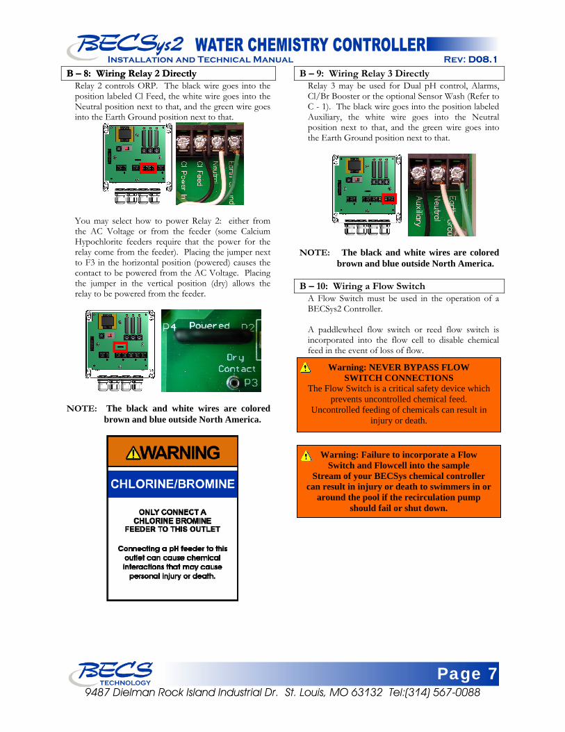
B – 8: Wiring Relay 2 Directly B – 8: Wiring Relay 2 Directly Relay 2 controls ORP. The black wire goes into the position labeled Cl Feed, the white wire goes into the Neutral position next to that, and the green wire goes into the Earth Ground position next to that.
You may select how to power Relay 2: either from the AC Voltage or from the feeder (some Calcium Hypochlorite feeders require that the power for the relay come from the feeder). Placing the jumper next to F3 in the horizontal position (powered) causes the contact to be powered from the AC Voltage. Placing the jumper in the vertical position (dry) allows the relay to be powered from the feeder.
NOTE: The black and white wires are colored brown and blue outside North America.
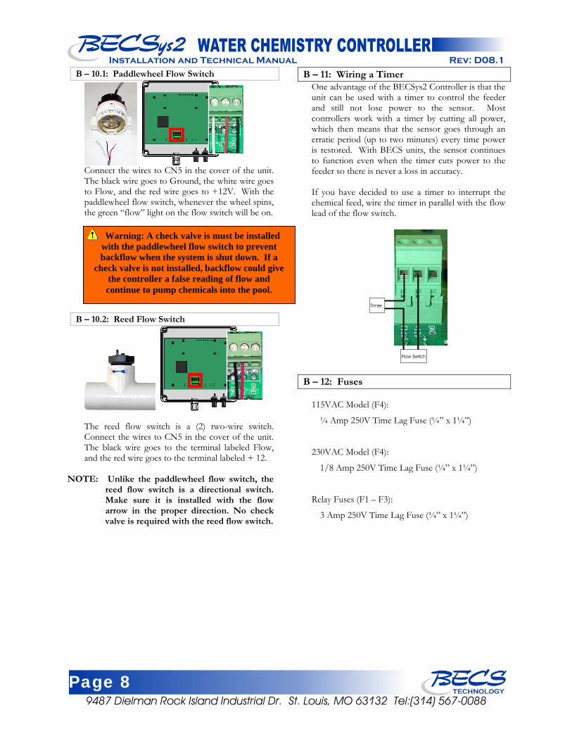
B – 9: Wiring Relay 3 Directly Relay 3 may be used for Dual pH control, Alarms, Cl/Br Booster or the optional Sensor Wash (Refer to C - 1). The black wire goes into the position labeled Auxiliary, the white wire goes into the Neutral position next to that, and the green wire goes into the Earth Ground position next to that.
NOTE: The black and white wires are colored brown and blue outside North America.
B – 10: Wiring a Flow Switch
A Flow Switch must be used in the operation of a BECSys2 Controller. A paddlewheel flow switch or reed flow switch is incorporated into the flow cell to disable chemical feed in the event of loss of flow.
Warning: NEVER BYPASS FLOW SWITCH CONNECTIONS
The Flow Switch is a critical safety device which prevents uncontrolled chemical feed.
Uncontrolled feeding of chemicals can result in injury or death.
Warning: Failure to incorporate a Flow Switch and Flowcell into the sample
Stream of your BECSys chemical controller can result in injury or death to swimmers in or
around the pool if the recirculation pump should fail or shut down.
Page 8 9487 Dielman Rock Island Industrial Dr. St. Louis, MO 63132 Tel:(314) 567-0088
Installation and Technical Manual Rev: D08.1
B – 10.1: Paddlewheel Flow Switch B – 11: Wiring a Timer
One advantage of the BECSys2 Controller is that the unit can be used with a timer to control the feeder and still not lose power to the sensor. Most controllers work with a timer by cutting all power, which then means that the sensor goes through an erratic period (up to two minutes) every time power is restored. With BECS units, the sensor continues to function even when the timer cuts power to the feeder so there is never a loss in accuracy. Connect the wires to CN5 in the cover of the unit.
The black wire goes to Ground, the white wire goes to Flow, and the red wire goes to +12V. With the paddlewheel flow switch, whenever the wheel spins, the green “flow” light on the flow switch will be on.
If you have decided to use a timer to interrupt the chemical feed, wire the timer in parallel with the flow lead of the flow switch.
Warning: A check valve is must be installed with the paddlewheel flow switch to prevent backflow when the system is shut down. If a
check valve is not installed, backflow could give the controller a false reading of flow and continue to pump chemicals into the pool.
Timer
Flow Switch
B – 10.2: Reed Flow Switch
B – 12: Fuses
115VAC Model (F4): ¼ Amp 250V Time Lag Fuse (¼” x 1¼”) The reed flow switch is a (2) two-wire switch. Connect the wires to CN5 in the cover of the unit. The black wire goes to the terminal labeled Flow, and the red wire goes to the terminal labeled + 12.
230VAC Model (F4):
1/8 Amp 250V Time Lag Fuse (¼” x 1¼”) NOTE: Unlike the paddlewheel flow switch, the
reed flow switch is a directional switch. Make sure it is installed with the flow arrow in the proper direction. No check valve is required with the reed flow switch.
Relay Fuses (F1 – F3):
3 Amp 250V Time Lag Fuse (¼” x 1¼”)
Page 9 9487 Dielman Rock Island Industrial Dr. St. Louis, MO 63132 Tel:(314) 567-0088
Installation and Technical Manual Rev: D08.1D08.1
Section C: Dip Switch SettingsSection C: Dip Switch Settings
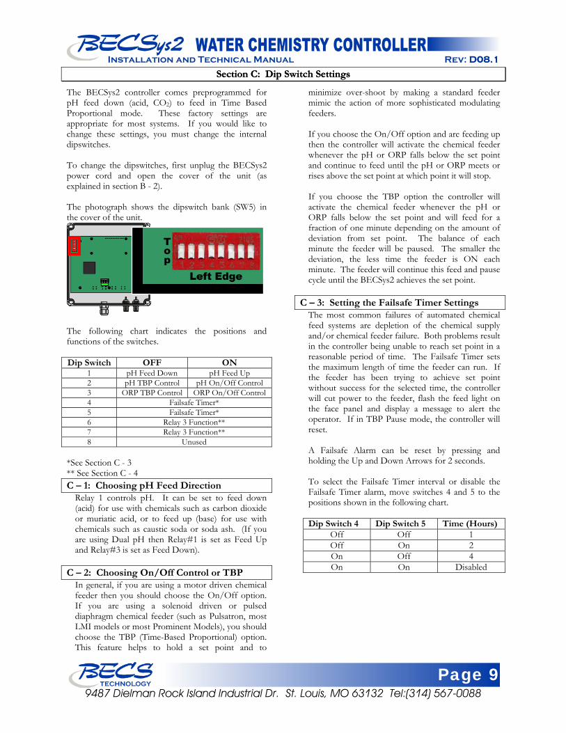
The BECSys2 controller comes preprogrammed for pH feed down (acid, CO2) to feed in Time Based Proportional mode. These factory settings are appropriate for most systems. If you would like to change these settings, you must change the internal dipswitches. To change the dipswitches, first unplug the BECSys2 power cord and open the cover of the unit (as explained in section B - 2). The photograph shows the dipswitch bank (SW5) in the cover of the unit.
The following chart indicates the positions and functions of the switches. Dip Switch OFF ON
1 pH Feed Down pH Feed Up 2 pH TBP Control pH On/Off Control 3 ORP TBP Control ORP On/Off Control4 Failsafe Timer* 5 Failsafe Timer* 6 Relay 3 Function** 7 Relay 3 Function** 8 Unused
*See Section C - 3 ** See Section C - 4 C – 1: Choosing pH Feed Direction
Relay 1 controls pH. It can be set to feed down (acid) for use with chemicals such as carbon dioxide or muriatic acid, or to feed up (base) for use with chemicals such as caustic soda or soda ash. (If you are using Dual pH then Relay#1 is set as Feed Up and Relay#3 is set as Feed Down).
C – 2: Choosing On/Off Control or TBP
In general, if you are using a motor driven chemical feeder then you should choose the On/Off option. If you are using a solenoid driven or pulsed diaphragm chemical feeder (such as Pulsatron, most LMI models or most Prominent Models), you should choose the TBP (Time-Based Proportional) option. This feature helps to hold a set point and to
minimize over-shoot by making a standard feeder mimic the action of more sophisticated modulating feeders. If you choose the On/Off option and are feeding up then the controller will activate the chemical feeder whenever the pH or ORP falls below the set point and continue to feed until the pH or ORP meets or rises above the set point at which point it will stop. If you choose the TBP option the controller will activate the chemical feeder whenever the pH or ORP falls below the set point and will feed for a fraction of one minute depending on the amount of deviation from set point. The balance of each minute the feeder will be paused. The smaller the deviation, the less time the feeder is ON each minute. The feeder will continue this feed and pause cycle until the BECSys2 achieves the set point.
C – 3: Setting the Failsafe Timer Settings The most common failures of automated chemical feed systems are depletion of the chemical supply and/or chemical feeder failure. Both problems result in the controller being unable to reach set point in a reasonable period of time. The Failsafe Timer sets the maximum length of time the feeder can run. If the feeder has been trying to achieve set point without success for the selected time, the controller will cut power to the feeder, flash the feed light on the face panel and display a message to alert the operator. If in TBP Pause mode, the controller will reset. A Failsafe Alarm can be reset by pressing and holding the Up and Down Arrows for 2 seconds. To select the Failsafe Timer interval or disable the Failsafe Timer alarm, move switches 4 and 5 to the positions shown in the following chart. Dip Switch 4 Dip Switch 5 Time (Hours)
Off Off 1 Off On 2 On Off 4 On On Disabled
Page 10 9487 Dielman Rock Island Industrial Dr. St. Louis, MO 63132 Tel:(314) 567-0088
Installation and Technical Manual Rev: D08.1
C – 4: Relay 3 Functions Relay 3 can be used for several different functions. To select the function of Relay 3 move switches 6 and 7 to the positions shown in the following chart: Dip Switch 6 Dip Switch 7 Function Off Off Sensor Wash Off On Dual pH Control On Off Alarm On On Cl/Br Booster
NOTE: You will only have an Alarm Relay when the dip switches are set accordingly. The Alarm LED will still flash when the controller is in Alarm.
C – 4.1: Sensor Wash
Setting Dip Switches 6 and 7 to the off position configures Relay 3 for Sensor Wash. The Sensor Wash will begin 12 hours from power-up, run for approximately 2 minutes, and then come on again every 24 hours after that running for a duration of 2 minutes.
C – 4.2: Dual pH Control Setting Dip Switch 6 to the off position and Dip Switch 7 to the on position configures Relay 3 for pH feed down. You must configure Relay 1 for Feed Up (Dip Switch 1 On).
C – 4.3: Alarm Relay With Dip Switch 6 set to the on position and Dip Switch 7 set to the off position, Relay 3 is configured for an alarm relay. The Alarm Relay will turn on any time there is an alarm state (No Flow, pH High, etc). Alarm points are set in the Programming Section of this manual (Section D).
C – 4.4: Cl/Br Booster Setting Dip Switches 6 and 7 to the on position configures Relay 3 for a sanitizer booster. When the ORP level drops to the Cl/Br Booster trigger set point, Relay 3 will activate an alternate sanitizer feed until the ORP reaches the Cl/Br Booster set point.
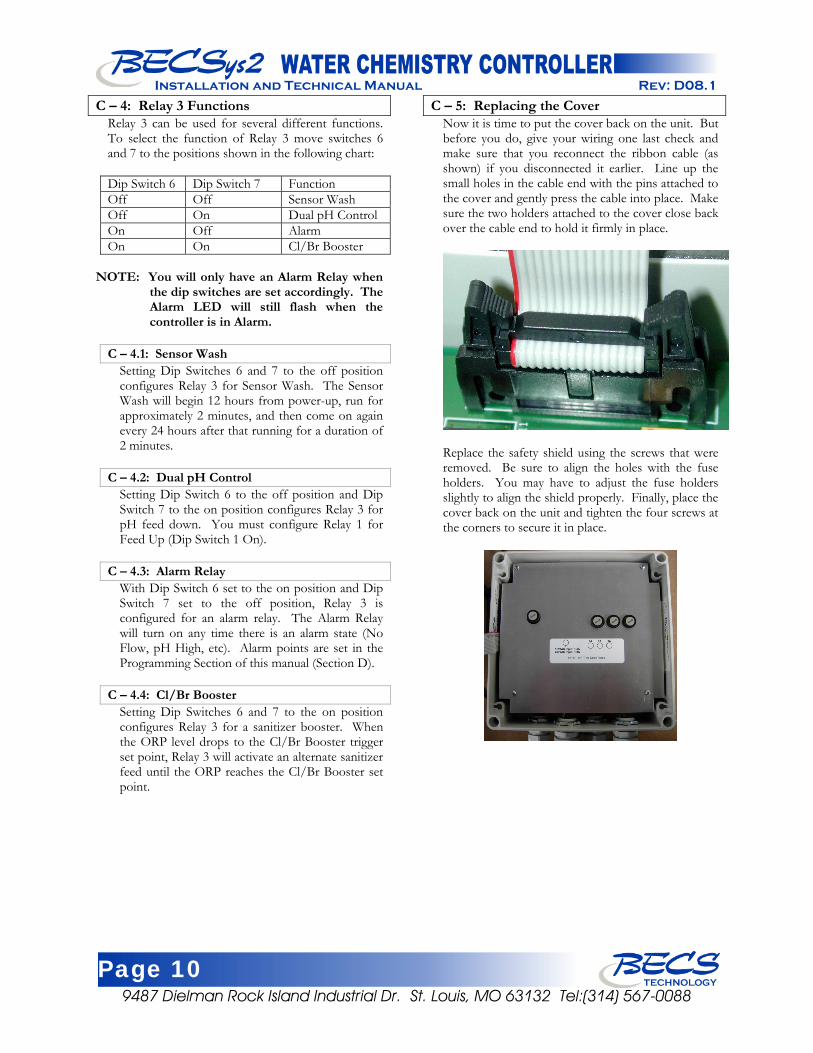
C – 5: Replacing the Cover Now it is time to put the cover back on the unit. But before you do, give your wiring one last check and make sure that you reconnect the ribbon cable (as shown) if you disconnected it earlier. Line up the small holes in the cable end with the pins attached to the cover and gently press the cable into place. Make sure the two holders attached to the cover close back over the cable end to hold it firmly in place.
Replace the safety shield using the screws that were removed. Be sure to align the holes with the fuse holders. You may have to adjust the fuse holders slightly to align the shield properly. Finally, place the cover back on the unit and tighten the four screws at the corners to secure it in place.
Page 11 9487 Dielman Rock Island Industrial Dr. St. Louis, MO 63132 Tel:(314) 567-0088
Installation and Technical Manual Rev: D08.1
Section D: Programming the Controller
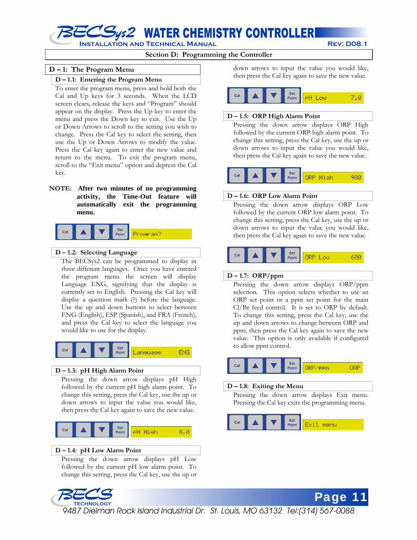
D – 1: The Program Menu D – 1.1: Entering the Program Menu To enter the program menu, press and hold both the Cal and Up keys for 3 seconds. When the LCD screen clears, release the keys and “Program” should appear on the display. Press the Up key to enter the menu and press the Down key to exit. Use the Up or Down Arrows to scroll to the setting you wish to change. Press the Cal key to select the setting, then use the Up or Down Arrows to modify the value. Press the Cal key again to enter the new value and return to the menu. To exit the program menu, scroll to the “Exit menu” option and depress the Cal key.
NOTE: After two minutes of no programming activity, the Time-Out feature will automatically exit the programming menu.
D – 1.2: Selecting Language
The BECSys2 can be programmed to display in three different languages. Once you have entered the program menu the screen will display Language ENG, signifying that the display is currently set to English. Pressing the Cal key will display a question mark (?) before the language. Use the up and down buttons to select between ENG (English), ESP (Spanish), and FRA (French), and press the Cal key to select the language you would like to use for the display.
D – 1.3: pH High Alarm Point
Pressing the down arrow displays pH High followed by the current pH high alarm point. To change this setting, press the Cal key, use the up or down arrows to input the value you would like, then press the Cal key again to save the new value.
D – 1.4: pH Low Alarm Point
Pressing the down arrow displays pH Low followed by the current pH low alarm point. To change this setting, press the Cal key, use the up or
down arrows to input the value you would like, then press the Cal key again to save the new value.
D – 1.5: ORP High Alarm Point
Pressing the down arrow displays ORP High followed by the current ORP high alarm point. To change this setting, press the Cal key, use the up or down arrows to input the value you would like, then press the Cal key again to save the new value.
D – 1.6: ORP Low Alarm Point
Pressing the down arrow displays ORP Low followed by the current ORP low alarm point. To change this setting, press the Cal key, use the up or down arrows to input the value you would like, then press the Cal key again to save the new value.
D – 1.7: ORP/ppm
Pressing the down arrow displays ORP/ppm selection. This option selects whether to use an ORP set point or a ppm set point for the main Cl/Br feed control. It is set to ORP by default. To change this setting, press the Cal key, use the up and down arrows to change between ORP and ppm, then press the Cal key again to save the new value. This option is only available if configured to allow ppm control.
D – 1.8: Exiting the Menu
Pressing the down arrow displays Exit menu. Pressing the Cal key exits the programming menu.
Page 12 9487 Dielman Rock Island Industrial Dr. St. Louis, MO 63132 Tel:(314) 567-0088
Installation and Technical Manual Rev: D08.1
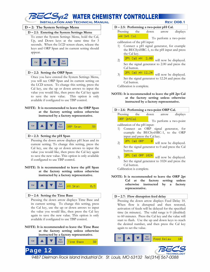
D – 2: The System Settings Menu D – 2.1: Entering the System Settings Menu
To enter the System Settings Menu, hold the Cal, Up, and Down keys at the same time for 3 seconds. When the LCD screen clears, release the keys and ORP Span and its current setting should appear.
D – 2.2: Setting the ORP Span Once you have entered the System Settings Menu, you will see ORP Span and its current setting on the LCD screen. To change this setting, press the Cal key, use the up or down arrows to input the value you would like, then press the Cal key again to save the new value. This option is only available if configured to use TBP control.
NOTE: It is recommended to leave the ORP Span at the factory setting unless otherwise instructed by a factory representative.
D – 2.3: Setting the pH Span Pressing the down arrow displays pH Scan and its current setting. To change this setting, press the Cal key, use the up or down arrows to input the value you would like, then press the Cal key again to save the new value. This option is only available if configured to use TBP control.
NOTE: It is recommended to leave the pH Span at the factory setting unless otherwise instructed by a factory representative.
D – 2.4: Setting the Time Base Pressing the down arrow displays Time Base and its current setting. To change this setting, press the Cal key, use the up or down arrows to input the value you would like, then press the Cal key again to save the new value. This option is only available if configured to use TBP control.
NOTE: It is recommended to leave the Time Base at the factory setting unless otherwise instructed by a factory representative.
D – 2.5: Performing a two-point pH Cal. Pressing the down arrow displays
. To perform a two-point calibration of the pH input: 1) Connect a pH signal generator, for example
the BECSysHRC-1, to the pH input and press the Cal key.
2) will now be displayed. Set the signal generator to 2.00 and press the Cal button.
3) will now be displayed. Set the signal generator to 12.24 and press the Cal button.
Calibration is complete.
NOTE: It is recommended to leave the pH 2pt Cal at the factory setting unless otherwise instructed by a factory representative.
D – 2.6: Performing a two-point ORP Cal.
Pressing the down arrow displays
. To perform a two-point calibration of the pH input: 1) Connect an ORP signal generator, for
example the BECSysHRC-1, to the ORP input and press the Cal key.
2) will now be displayed. Set the signal generator to 0 and press the Cal button.
3) will now be displayed. Set the signal generator to 1024 and press the Cal button.
Calibration is complete.
NOTE: It is recommended to leave the ORP 2pt Cal at the factory setting unless otherwise instructed by a factory representative.
D – 2.7: Flow disruption feed delay
Pressing the down arrow displays Feed Delay 10. When flow is disrupted and then restored, activation of feeds will be delayed for the specified time (in minutes). The valid range is 0 (disabled) to 60 minutes. Press the Cal key and the value will start to flash. Use the up and down keys to reach the desired number, and then press the Cal key again to set the value.
Page 13 9487 Dielman Rock Island Industrial Dr. St. Louis, MO 63132 Tel:(314) 567-0088
Installation and Technical Manual Rev: D08.1
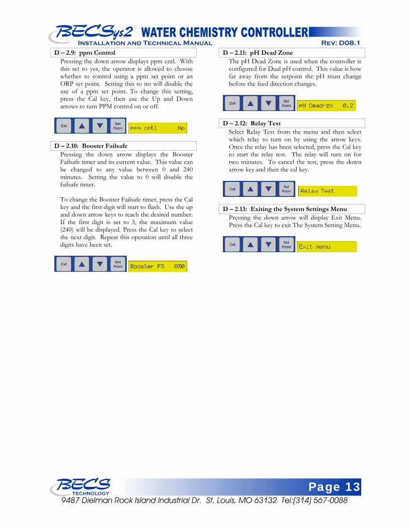
D – 2.9: ppm Control D – 2.11: pH Dead Zone Pressing the down arrow displays ppm cntl. With this set to yes, the operator is allowed to choose whether to control using a ppm set point or an ORP set point. Setting this to no will disable the use of a ppm set point. To change this setting, press the Cal key, then use the Up and Down arrows to turn PPM control on or off.
The pH Dead Zone is used when the controller is configured for Dual pH control. This value is how far away from the setpoint the pH must change before the feed direction changes.
D – 2.12: Relay Test
Select Relay Test from the menu and then select which relay to turn on by using the arrow keys. Once the relay has been selected, press the Cal key to start the relay test. The relay will turn on for two minutes. To cancel the test, press the down arrow key and then the cal key.
D – 2.10: Booster Failsafe
Pressing the down arrow displays the Booster Failsafe timer and its current value. This value can be changed to any value between 0 and 240 minutes. Setting the value to 0 will disable the failsafe timer.
To change the Booster Failsafe timer, press the Cal key and the first digit will start to flash. Use the up and down arrow keys to reach the desired number. If the first digit is set to 3, the maximum value (240) will be displayed. Press the Cal key to select the next digit. Repeat this operation until all three digits have been set.
D – 2.13: Exiting the System Settings Menu
Pressing the down arrow will display Exit Menu. Press the Cal key to exit The System Setting Menu.
Page 14 9487 Dielman Rock Island Industrial Dr. St. Louis, MO 63132 Tel:(314) 567-0088
Installation and Technical Manual Rev: D08.1
Section E: Normal Operation
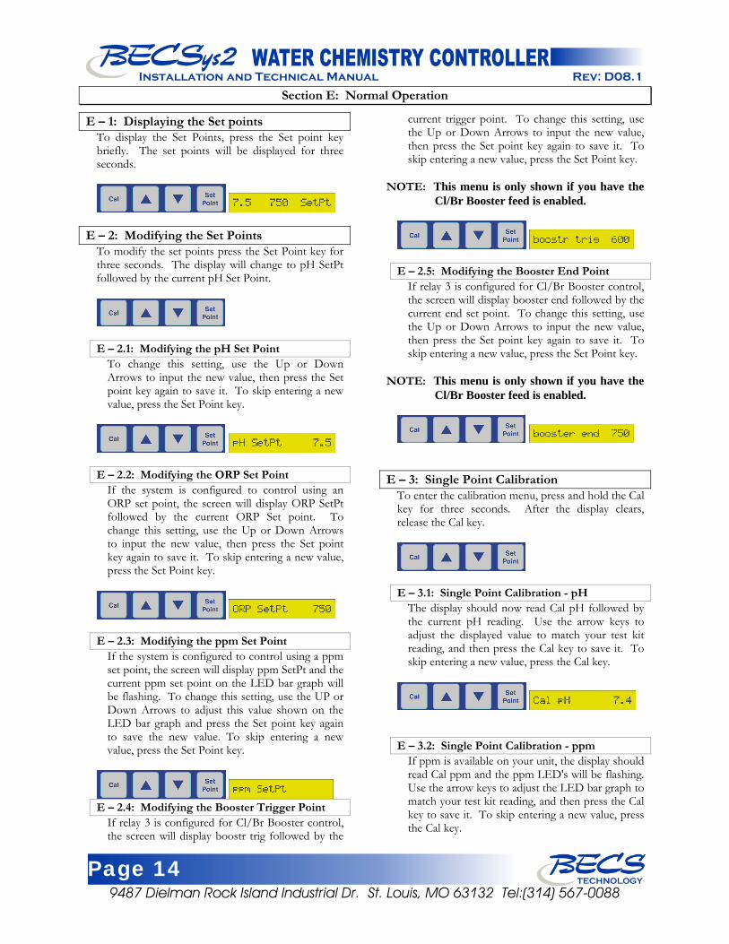
E – 1: Displaying the Set points To display the Set Points, press the Set point key briefly. The set points will be displayed for three seconds.
E – 2: Modifying the Set Points To modify the set points press the Set Point key for three seconds. The display will change to pH SetPt followed by the current pH Set Point.
E – 2.1: Modifying the pH Set Point
To change this setting, use the Up or Down Arrows to input the new value, then press the Set point key again to save it. To skip entering a new value, press the Set Point key.
E – 2.2: Modifying the ORP Set Point If the system is configured to control using an ORP set point, the screen will display ORP SetPt followed by the current ORP Set point. To change this setting, use the Up or Down Arrows to input the new value, then press the Set point key again to save it. To skip entering a new value, press the Set Point key.
E – 2.3: Modifying the ppm Set Point
If the system is configured to control using a ppm set point, the screen will display ppm SetPt and the current ppm set point on the LED bar graph will be flashing. To change this setting, use the UP or Down Arrows to adjust this value shown on the LED bar graph and press the Set point key again to save the new value. To skip entering a new value, press the Set Point key.
E – 2.4: Modifying the Booster Trigger Point
If relay 3 is configured for Cl/Br Booster control, the screen will display boostr trig followed by the
current trigger point. To change this setting, use the Up or Down Arrows to input the new value, then press the Set point key again to save it. To skip entering a new value, press the Set Point key.
NOTE: This menu is only shown if you have the Cl/Br Booster feed is enabled.
E – 2.5: Modifying the Booster End Point If relay 3 is configured for Cl/Br Booster control, the screen will display booster end followed by the current end set point. To change this setting, use the Up or Down Arrows to input the new value, then press the Set point key again to save it. To skip entering a new value, press the Set Point key.
NOTE: This menu is only shown if you have the Cl/Br Booster feed is enabled.
E – 3: Single Point Calibration To enter the calibration menu, press and hold the Cal key for three seconds. After the display clears, release the Cal key.
E – 3.1: Single Point Calibration - pH
The display should now read Cal pH followed by the current pH reading. Use the arrow keys to adjust the displayed value to match your test kit reading, and then press the Cal key to save it. To skip entering a new value, press the Cal key.
E – 3.2: Single Point Calibration - ppm If ppm is available on your unit, the display should read Cal ppm and the ppm LED's will be flashing. Use the arrow keys to adjust the LED bar graph to match your test kit reading, and then press the Cal key to save it. To skip entering a new value, press the Cal key.
Page 15 9487 Dielman Rock Island Industrial Dr. St. Louis, MO 63132 Tel:(314) 567-0088
Installation and Technical Manual Rev: D08.1
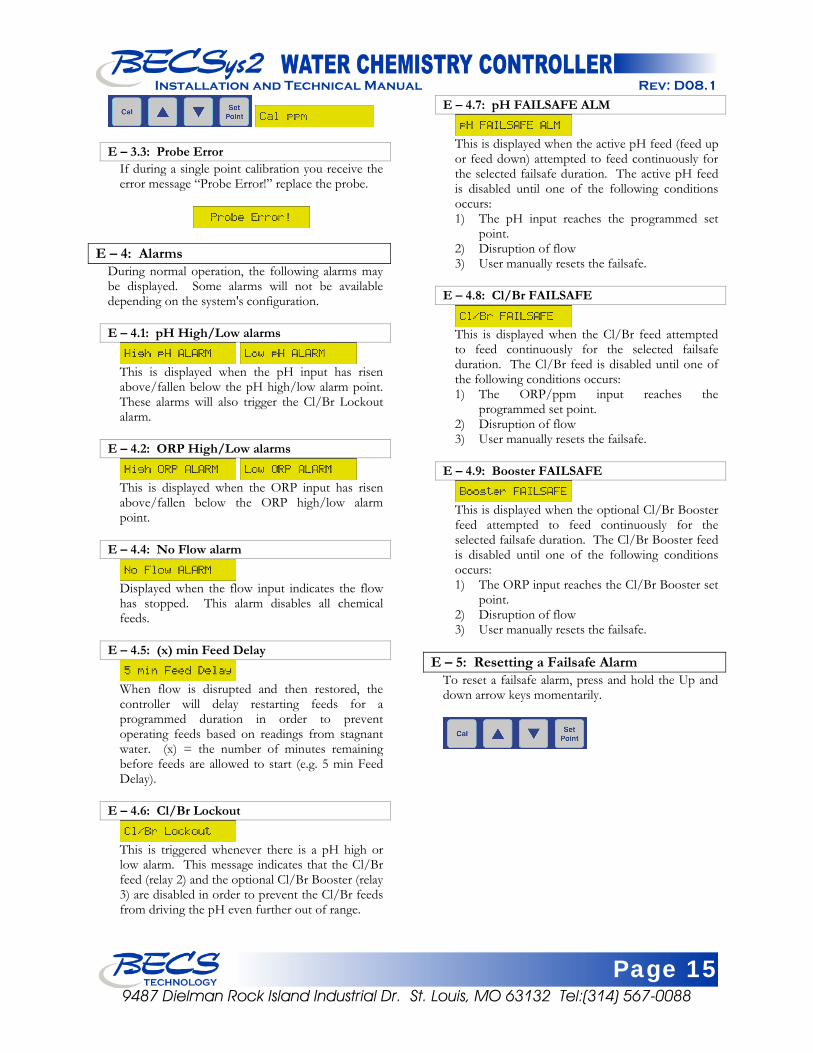
E – 3.3: Probe Error
If during a single point calibration you receive the error message “Probe Error!” replace the probe.
E – 4: Alarms During normal operation, the following alarms may be displayed. Some alarms will not be available depending on the system's configuration. E – 4.1: pH High/Low alarms
This is displayed when the pH input has risen above/fallen below the pH high/low alarm point. These alarms will also trigger the Cl/Br Lockout alarm.
E – 4.2: ORP High/Low alarms
This is displayed when the ORP input has risen above/fallen below the ORP high/low alarm point.
E – 4.4: No Flow alarm
Displayed when the flow input indicates the flow has stopped. This alarm disables all chemical feeds.
E – 4.5: (x) min Feed Delay
When flow is disrupted and then restored, the controller will delay restarting feeds for a programmed duration in order to prevent operating feeds based on readings from stagnant water. (x) = the number of minutes remaining before feeds are allowed to start (e.g. 5 min Feed Delay).
E – 4.6: Cl/Br Lockout
This is triggered whenever there is a pH high or low alarm. This message indicates that the Cl/Br feed (relay 2) and the optional Cl/Br Booster (relay 3) are disabled in order to prevent the Cl/Br feeds from driving the pH even further out of range.
E – 4.7: pH FAILSAFE ALM
This is displayed when the active pH feed (feed up or feed down) attempted to feed continuously for the selected failsafe duration. The active pH feed is disabled until one of the following conditions occurs: 1) The pH input reaches the programmed set
point. 2) Disruption of flow 3) User manually resets the failsafe.
E – 4.8: Cl/Br FAILSAFE
This is displayed when the Cl/Br feed attempted to feed continuously for the selected failsafe duration. The Cl/Br feed is disabled until one of the following conditions occurs: 1) The ORP/ppm input reaches the
programmed set point. 2) Disruption of flow 3) User manually resets the failsafe.
E – 4.9: Booster FAILSAFE
This is displayed when the optional Cl/Br Booster feed attempted to feed continuously for the selected failsafe duration. The Cl/Br Booster feed is disabled until one of the following conditions occurs: 1) The ORP input reaches the Cl/Br Booster set
point. 2) Disruption of flow 3) User manually resets the failsafe.
E – 5: Resetting a Failsafe Alarm
To reset a failsafe alarm, press and hold the Up and down arrow keys momentarily.
Page 16 9487 Dielman Rock Island Industrial Dr. St. Louis, MO 63132 Tel:(314) 567-0088
Installation and Technical Manual Rev: D08.1
Section F: Maintenance
The BECSys2 requires no maintenance other than a periodic calibration check and sensor cleaning. F – 1: Potentiometric Sensors (pH and ORP)
F – 1.1: Electrode Cleaning: Slow response time and large offsets may indicate the electrode has become coated. The nature of the coating will dictate the type of cleaning technique that should be used.
Soft coatings, like bacterial films, are best removed using a squirt bottle or the water jet from a faucet. If this is not successful, then gently wipe with a soft wet cloth. For a more severe coating, first try a strong detergent (something similar to Dawn liquid detergent) and warm water, using a soft brush (like a toothbrush). Isopropyl alcohol on a Q-tip is another good choice. Rinse the measuring end in distilled water before reinstallation. Greasy and oily coatings are best removed with a detergent solution or a solvent that will not attack the sensor body. Methanol and isopropyl alcohol are good choices for solvents. Acetone, MEK, THF, or trichloroethane will irreparably harm the electrode. Hard coatings, like calcium or lime scale, are best removed with a solvent appropriate for the particular coating. A 5% solution of hydrochloric acid (HCl) would be a good choice for calcium scale. If unsure of the proper solvent to remove a hard mineral coating, then alternate between a 5% hydrochloric acid and a 4% sodium hydroxide (NaOH) for 10 minutes each. After treating the electrode with these strong acids or bases, rinse the electrode with water and soak it in a pH 4 buffer for at least 1/2 hour. The platinum tip of an ORP sensor can be cleaned with an abrasive as a last resort. Gently scour the platinum with a 600 grit wet emery cloth, or preferably, a 1-3 micron alumina polishing powder.
F – 1.2: Long-Term Storage: Save the wetting cap that came with the sensor for long-term storage. After removing the sensor from the flow-cell, clean it as in routine maintenance, and then store it in the wetting cap using a pH 4 buffer saturated with potassium chloride (KCl). The potassium chloride will prevent electrolyte from leaching out of the sensors reference cell. The wetting cap only needs to be half full. If a number of sites are going to be serviced, for example, at the end of a season, then it might be a good idea to carry a pint of 4.0/KCl storage solution.
Warning: You may lightly blot the water On a pH sensor tip on a paper towel, but never vigorously rub or wipe the pH bulb because this may scratch the delicate outer layer on the pH
glass impairing its response.
Page 17 9487 Dielman Rock Island Industrial Dr. St. Louis, MO 63132 Tel:(314) 567-0088
Installation and Technical Manual Rev: D08.1
Section G: Feed Charts
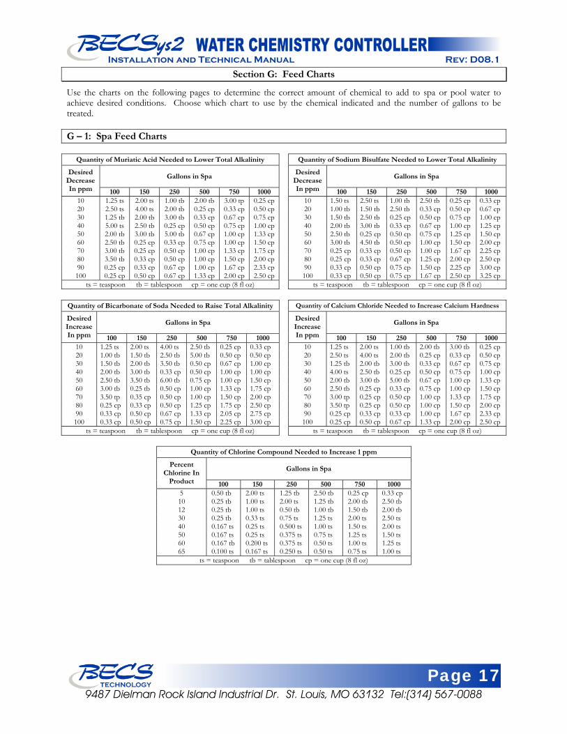
Use the charts on the following pages to determine the correct amount of chemical to add to spa or pool water to achieve desired conditions. Choose which chart to use by the chemical indicated and the number of gallons to be treated. G – 1: Spa Feed Charts
Quantity of Muriatic Acid Needed to Lower Total Alkalinity
Gallons in Spa Desired Decrease In ppm 100 150 250 500 750 1000
10 1.25 ts 2.00 ts 1.00 tb 2.00 tb 3.00 tp 0.25 cp20 2.50 ts 4.00 ts 2.00 tb 0.25 cp 0.33 cp 0.50 cp30 1.25 tb 2.00 tb 3.00 tb 0.33 cp 0.67 cp 0.75 cp40 5.00 ts 2.50 tb 0.25 cp 0.50 cp 0.75 cp 1.00 cp50 2.00 tb 3.00 tb 5.00 tb 0.67 cp 1.00 cp 1.33 cp60 2.50 tb 0.25 cp 0.33 cp 0.75 cp 1.00 cp 1.50 cp70 3.00 tb 0.25 cp 0.50 cp 1.00 cp 1.33 cp 1.75 cp80 3.50 tb 0.33 cp 0.50 cp 1.00 cp 1.50 cp 2.00 cp90 0.25 cp 0.33 cp 0.67 cp 1.00 cp 1.67 cp 2.33 cp100 0.25 cp 0.50 cp 0.67 cp 1.33 cp 2.00 cp 2.50 cp
ts = teaspoon tb = tablespoon cp = one cup (8 fl oz)
Quantity of Sodium Bisulfate Needed to Lower Total Alkalinity
Gallons in Spa Desired Decrease In ppm 100 150 250 500 750 1000
10 1.50 ts 2.50 ts 1.00 tb 2.50 tb 0.25 cp 0.33 cp 20 1.00 tb 1.50 tb 2.50 tb 0.33 cp 0.50 cp 0.67 cp 30 1.50 tb 2.50 tb 0.25 cp 0.50 cp 0.75 cp 1.00 cp 40 2.00 tb 3.00 tb 0.33 cp 0.67 cp 1.00 cp 1.25 cp 50 2.50 tb 0.25 cp 0.50 cp 0.75 cp 1.25 cp 1.50 cp 60 3.00 tb 4.50 tb 0.50 cp 1.00 cp 1.50 cp 2.00 cp 70 0.25 cp 0.33 cp 0.50 cp 1.00 cp 1.67 cp 2.25 cp 80 0.25 cp 0.33 cp 0.67 cp 1.25 cp 2.00 cp 2.50 cp 90 0.33 cp 0.50 cp 0.75 cp 1.50 cp 2.25 cp 3.00 cp 100 0.33 cp 0.50 cp 0.75 cp 1.67 cp 2.50 cp 3.25 cp
ts = teaspoon tb = tablespoon cp = one cup (8 fl oz)
Quantity of Bicarbonate of Soda Needed to Raise Total Alkalinity
Gallons in Spa Desired Increase In ppm 100 150 250 500 750 1000
10 1.25 ts 2.00 ts 4.00 ts 2.50 tb 0.25 cp 0.33 cp 20 1.00 tb 1.50 tb 2.50 tb 5.00 tb 0.50 cp 0.50 cp 30 1.50 tb 2.00 tb 3.50 tb 0.50 cp 0.67 cp 1.00 cp 40 2.00 tb 3.00 tb 0.33 cp 0.50 cp 1.00 cp 1.00 cp 50 2.50 tb 3.50 tb 6.00 tb 0.75 cp 1.00 cp 1.50 cp 60 3.00 tb 0.25 tb 0.50 cp 1.00 cp 1.33 cp 1.75 cp 70 3.50 tp 0.35 cp 0.50 cp 1.00 cp 1.50 cp 2.00 cp 80 0.25 cp 0.33 cp 0.50 cp 1.25 cp 1.75 cp 2.50 cp 90 0.33 cp 0.50 cp 0.67 cp 1.33 cp 2.05 cp 2.75 cp 100 0.33 cp 0.50 cp 0.75 cp 1.50 cp 2.25 cp 3.00 cp
ts = teaspoon tb = tablespoon cp = one cup (8 fl oz)
Quantity of Calcium Chloride Needed to Increase Calcium Hardness
Gallons in Spa Desired Increase In ppm 100 150 250 500 750 1000
10 1.25 ts 2.00 ts 1.00 tb 2.00 tb 3.00 tb 0.25 cp 20 2.50 ts 4.00 ts 2.00 tb 0.25 cp 0.33 cp 0.50 cp 30 1.25 tb 2.00 tb 3.00 tb 0.33 cp 0.67 cp 0.75 cp 40 4.00 ts 2.50 tb 0.25 cp 0.50 cp 0.75 cp 1.00 cp 50 2.00 tb 3.00 tb 5.00 tb 0.67 cp 1.00 cp 1.33 cp 60 2.50 tb 0.25 cp 0.33 cp 0.75 cp 1.00 cp 1.50 cp 70 3.00 tp 0.25 cp 0.50 cp 1.00 cp 1.33 cp 1.75 cp 80 3.50 tp 0.25 cp 0.50 cp 1.00 cp 1.50 cp 2.00 cp 90 0.25 cp 0.33 cp 0.33 cp 1.00 cp 1.67 cp 2.33 cp 100 0.25 cp 0.50 cp 0.67 cp 1.33 cp 2.00 cp 2.50 cp
ts = teaspoon tb = tablespoon cp = one cup (8 fl oz)
Quantity of Chlorine Compound Needed to Increase 1 ppm
Gallons in Spa Percent Chlorine In
Product 100 150 250 500 750 1000 5 0.50 tb 2.00 ts 1.25 tb 2.50 tb 0.25 cp 0.33 cp 10 0.25 tb 1.00 ts 2.00 ts 1.25 tb 2.00 tb 2.50 tb 12 0.25 tb 1.00 ts 0.50 tb 1.00 tb 1.50 tb 2.00 tb 30 0.25 tb 0.33 ts 0.75 ts 1.25 ts 2.00 ts 2.50 ts 40 0.167 ts 0.25 ts 0.500 ts 1.00 ts 1.50 ts 2.00 ts 50 0.167 ts 0.25 ts 0.375 ts 0.75 ts 1.25 ts 1.50 ts 60 0.167 tb 0.200 ts 0.375 ts 0.50 ts 1.00 ts 1.25 ts 65 0.100 ts 0.167 ts 0.250 ts 0.50 ts 0.75 ts 1.00 ts
ts = teaspoon tb = tablespoon cp = one cup (8 fl oz)
Page 18 9487 Dielman Rock Island Industrial Dr. St. Louis, MO 63132 Tel:(314) 567-0088
Installation and Technical Manual Rev: D08.1
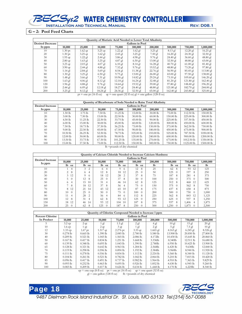
G – 2: Pool Feed Charts
Quantity of Muriatic Acid Needed to Lower Total Alkalinity Gallons in Pool Desired Decrease
In ppm 10,000 25,000 50,000 75,000 100,000 200,000 500,000 750,000 1,000,000 10 1.30 pt 1.62 qt 3.25 qt 1.22 gl 1.62 gl 3.25 gl 8.13 gl 12.20 gl 16.25 gl 20 1.30 pt 3.25 qt 1.62 gl 2.43 gl 3.25 gl 7.50 gl 16.20 gl 24.30 gl 32.50 gl 30 1.95 qt 1.22 gl 2.44 gl 3.86 gl 4.98 gl 9.76 gl 24.40 gl 36.60 gl 48.80 gl 40 2.80 qt 1.63 gl 3.25 gl 4.87 gl 6.50 gl 13.00 gl 32.50 gl 48.80 gl 65.00 gl 50 3.25 qt 2.03 gl 4.07 gl 6.10 gl 8.14 gl 16.28 gl 40.70 gl 61.00 gl 81.40 gl 60 3.90 qt 2.44 gl 4.88 gl 7.32 gl 9.76 gl 19.52 gl 48.80 gl 73.20 gl 97.80 gl 70 1.14 gl 2.84 gl 5.69 gl 8.54 gl 11.38 gl 22.76 gl 56.90 gl 85.45 gl 113.80 gl 80 1.30 gl 3.25 gl 6.50 gl 9.75 gl 13.00 gl 26.00 gl 65.00 gl 97.50 gl 138.00 gl 90 1.48 gl 3.66 gl 7.31 gl 10.96 gl 14.82 gl 29.24 gl 73.10 gl 109.60 gl 146.20 gl 100 1.63 gl 4.06 gl 8.12 gl 12.18 gl 16.24 gl 32.48 gl 81.20 gl 121.80 gl 162.40 gl 120 1.96 gl 4.88 gl 9.76 gl 14.64 gl 19.52 gl 39.00 gl 97.80 gl 148.40 gl 196.20 gl 150 2.44 gl 6.09 gl 12.18 gl 18.27 gl 24.40 gl 48.80 gl 121.80 gl 182.70 gl 244.00 gl 200 3.25 gl 8.12 gl 18.24 gl 24.36 gl 32.50 gl 65.00 gl 162.40 gl 243.80 gl 325.00 gl
pt = one pt (16 fl oz) qt = one quart (32 fl oz) gl = one gallon (128 fl oz)
Quantity of Bicarbonate of Soda Needed to Raise Total Alkalinity Gallons in Pool Desired Increase
In ppm 10,000 25,000 50,000 75,000 100,000 200,000 500,000 750,000 1,000,000 10 1.50 lb 3.75 lb 7.50 lb 11.25 lb 15.00 lb 30.00 lb 75.00 lb 112.50 lb 150.00 lb 20 3.00 lb 7.50 lb 15.00 lb 22.50 lb 30.00 lb 60.00 lb 150.00 lb 225.00 lb 300.00 lb 30 4.50 lb 11.25 lb 22.50 lb 33.75 lb 45.00 lb 90.00 lb 225.00 lb 337.50 lb 450.00 lb 40 6.00 lb 15.00 lb 30.00 lb 45.00 lb 60.00 lb 120.00 lb 300.00 lb 450.00 lb 600.00 lb 50 7.50 lb 18.75 lb 37.50 lb 56.25 lb 75.00 lb 150.00 lb 375.00 lb 562.50 lb 750.00 lb 60 9.00 lb 22.50 lb 45.00 lb 67.50 lb 90.00 lb 180.00 lb 450.00 lb 675.00 lb 900.00 lb 70 10.50 lb 26.25 lb 52.50 lb 78.75 lb 105.00 lb 210.00 lb 525.00 lb 787.50 lb 1050.00 lb 80 12.00 lb 30.00 lb 60.00 lb 90.00 lb 120.00 lb 240.00 lb 600.00 lb 900.00 lb 1200.00 lb 90 13.50 lb 33.75 lb 67.50 lb 101.25 lb 135.00 lb 270.00 lb 675.00 lb 1012.50 lb 1350.00 lb 100 15.00 lb 37.50 lb 75.00 lb 112.50 lb 150.00 lb 300.00 lb 750.00 lb 1125.00 lb 1500.00 lb
lb =pounds of dry chemical
Quantity of Calcium Chloride Needed to Increase Calcium Hardness Gallons in Pool
10,000 25,000 50,000 75,000 100,000 200,000 500,000 750,000 1,000,000 Desired Increase In ppm lb oz lb oz lb oz lb oz lb oz lb lb oz lb oz lb
10 1 4 3 2 6 4 9 6 12 8 25 62 8 93 12 125 20 2 8 6 4 12 8 18 12 25 0 50 125 0 197 8 250 30 3 12 9 6 18 12 28 2 37 8 75 187 8 281 4 375 40 5 0 12 8 25 0 37 8 50 0 100 250 0 375 0 500 50 6 4 15 10 31 4 46 14 62 8 125 312 8 468 12 625 60 7 8 18 12 37 8 56 4 75 0 150 375 0 562 8 750 70 8 12 21 14 43 12 65 10 87 8 175 437 8 658 4 875 80 10 0 25 0 50 0 75 0 100 0 200 500 0 750 0 1,000 90 11 4 28 2 56 4 84 6 112 8 225 562 8 843 12 1,125 100 12 8 31 4 62 8 93 12 125 0 250 625 0 937 8 1,250 150 18 12 46 14 93 12 104 10 187 8 375 937 8 1,406 4 1,875 200 25 0 62 8 125 0 187 8 250 0 500 1,250 0 1,875 0 2,500
Quantity of Chlorine Compound Needed to Increase 1 ppm
Gallons in Pool Percent Chlorine In Product 10,000 25,000 50,000 75,000 100,000 200,000 500,000 750,000 1,000,000
5 3.2 cp 2 qt 1 gl 1.5 gl 2 gl 4 gl 10 gl 15 gl 20 gl 10 1.6 cp 1 qt 2 qt 3 qt 1 gl 2 gl 5 gl 7.5 gl 10 gl 12 1.33 cp 1.67 pt 1.517 qt 2.276 pt 3.33 qt 1.665 gl 4.163 gl 6.245 gl 8.326 gl 30 0.278 lb 0.665 lb 1.390 lb 2.085 lb 2.780 lb 5.580 lb 13.900 lb 20.850 lb 27.800 lb 40 0.209 lb 0.521 lb 1.043 lb 1.565 lb 2.086 lb 4.172lb 10.430 lb 15.645 lb 20.860 lb 50 0.167 lb 0.417 lb 0.834 lb 1.251 lb 1.668 lb 3.336lb 8.340lb 12.511 lb 16.680 lb 60 0.139 lb 0.348 lb 0.695 lb 1.043 lb 1.390 lb 2.780lb 6.950 lb 10.425 lb 13.900 lb 65 0.128 lb 0.321 lb 0.642 lb 0.963 lb 1.284 lb 2.568lb 6.420 lb 9.630lb 12.840 lb 70 0.119 lb 0.298 lb 0.596 lb 0.894 lb 1.192 lb 2.384lb 5.960lb 8.940 lb 11.920 lb 75 0.111 lb 0.278 lb 0.556 lb 0.834 lb 1.112 lb 2.224 lb 5.560 lb 8.340 lb 11.120 lb 80 0.104 lb 0.261 lb 0.521 lb 0.782 lb 1.042 lb 2.064 lb 5.210 lb 7.815 lb 10.420 lb 85 0.096 lb 0.417 lb 0.491 lb 0.737 lb 0.982 lb 1.964 lb 4.910 lb 7.365 lb 9.829 lb 90 0.093 lb 0.232 lb 0.463 lb 0.695 lb 0.926 lb 1.852 lb 4.630 lb 6.945 lb 9.260 lb 100 0.083 lb 0.209 lb 0.417 lb 0.626 lb 0.634 lb 1..668 lb 4.170 lb 6.225lb 8.340 lb
cp = one cup (8 fl oz) pt = one pt (16 fl oz) qt = one quart (32 fl oz) gl = one gallon (128 fl oz) lb =pounds of dry chemical
Page 19 9487 Dielman Rock Island Industrial Dr. St. Louis, MO 63132 Tel:(314) 567-0088
Installation and Technical Manual Rev: D08.1D08.1
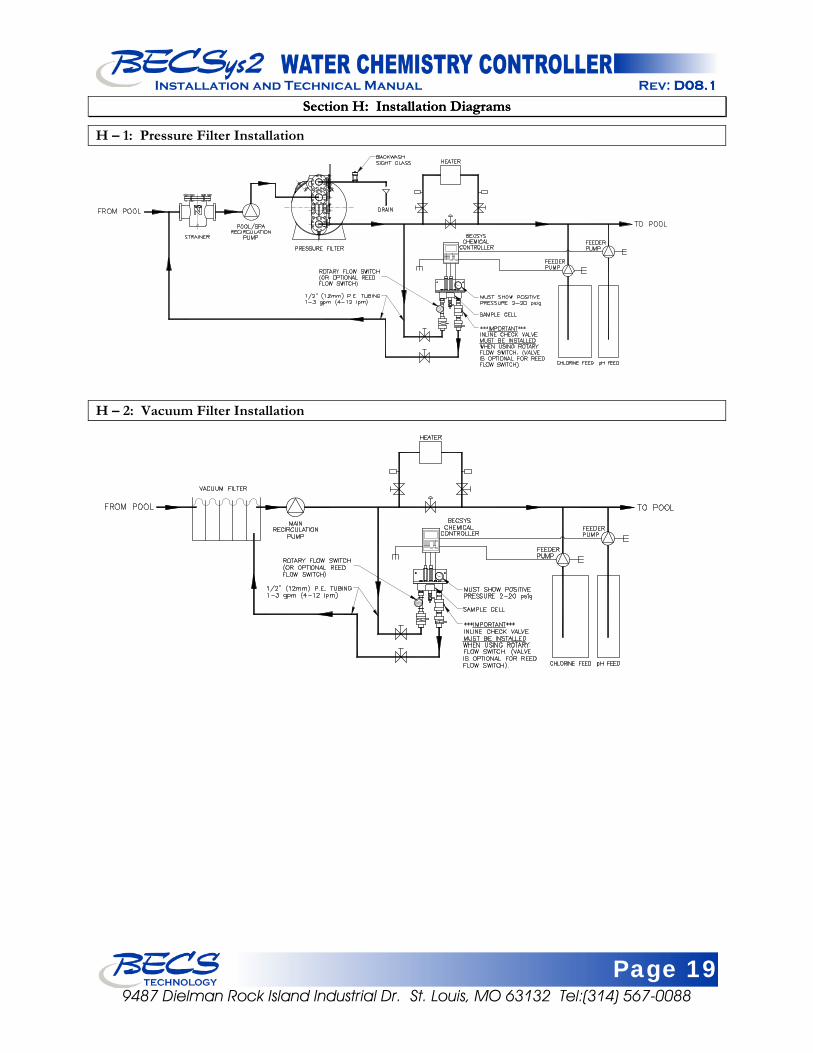
Section H: Installation Diagrams Section H: Installation Diagrams
H – 1: Pressure Filter Installation
H – 2: Vacuum Filter Installation
Page 20 9487 Dielman Rock Island Industrial Dr. St. Louis, MO 63132 Tel:(314) 567-0088
Installation and Technical Manual Rev: D08.1
Section I: Warranty
LIMITED WARRANTY BECS warrants the controller electronics and flow cell against any defect in workmanship or materials for a period of two years from the date of shipment. BECS warrants the pH and ORP sensors against any defect in workmanship or materials for a period of one year from the date of shipment. In the event of a component failure due to any defect in workmanship or materials, BECS will repair, or if repair is not possible, replace the defective part or parts of the BECSys controller. BECS will have the sole right to determine whether to repair or replace a product. BECS will not be responsible for any expense associated with installation of repaired or replacement parts. LIMITATIONS AND EXCLUSIONS This is a LIMITED WARRANTY. BECS makes NO WARRANTIES other than those contained herein. The LIMITED WARRANTY replaces and is in lieu of any WARRANTIES of MERCHANTABILITY or of FITNESS FOR A PARTICULAR PURPOSE which are expressly DISCLAIMED. All GENERAL, SPECIAL, INDIRECT, INCIDENTAL AND/OR CONSEQUENTIAL DAMAGES ARE EXCLUDED AND DISCLAIMED. This Limited Warranty is governed by Missouri Law and all disputes related to or arising from this transaction or Limited Warranty shall be resolved in Circuit Court of St. Louis County, Missouri. Any claims under this Limited Warranty must be brought within ONE YEAR after the cause of action accrued.
Document Part Number: 8620010-D08.1
April 2008 9487 Dielman Rock Island Industrial Dr. St. Louis, MO 63132 Tel:(314) 567-0088
Installation and Technical Manual Rev: D08.1D08.1
has been designing and manufacturing the industry’s
most reliable water chemistry controller for over 15 years. Our 24,000 ft2 facility in Saint Louis, Missouri is home to an exceptional design team, and all manufacturing is performed onsite at this facility where we can personally assure the quality of our products. The BECS commitment to excellence drives the most innovative new products and unparalleled customer service.
has been designing and manufacturing the industry’s most reliable water chemistry controller for over 15 years. Our 24,000 ft2 facility in Saint Louis, Missouri is home to an exceptional design team, and all manufacturing is performed onsite at this facility where we can personally assure the quality of our products. The BECS commitment to excellence drives the most innovative new products and unparalleled customer service.
BECSTECHNOLOGY Inc.


![DnV-RP-E302 - Design and Installation of Plate Anchors in Clay [2000]](https://static.fdocuments.net/doc/165x107/577ccd5c1a28ab9e788c1d8c/dnv-rp-e302-design-and-installation-of-plate-anchors-in-clay-2000.jpg)


