CODE 3 OECD STANDARD CODE OF PROTECTIVE STRUCTURES …
54
CODE 3 – February 2016 1 CODE 3 OECD STANDARD CODE FOR THE OFFICIAL TESTING OF PROTECTIVE STRUCTURES ON AGRICULTURAL AND FORESTRY TRACTORS (DYNAMIC TEST)
Transcript of CODE 3 OECD STANDARD CODE OF PROTECTIVE STRUCTURES …

CODE 3 – February 2016
1
CODE 3
OECD STANDARD CODE
FOR THE OFFICIAL TESTING
OF PROTECTIVE STRUCTURES ON
AGRICULTURAL AND FORESTRY TRACTORS
(DYNAMIC TEST)
CODE 3 – February 2016
2
TABLE OF CONTENTS
1. DEFINITIONS ..................................................................................................................................... 3 1.1 Agricultural and forestry tractors ................................................................................................ 3 1.2 Rolling Over Protective Structure (ROPS) .................................................................................. 3 1.3 Track ............................................................................................................................................ 3 1.4 Wheelbase .................................................................................................................................... 4 1.5 Determination of seat index point; Seat location and adjustment for test ................................... 4 1.6 Clearance zone ............................................................................................................................. 4 1.7 Unballasted mass ......................................................................................................................... 6 1.8 Permissible measurement tolerances ........................................................................................... 6 1.9 Symbols ....................................................................................................................................... 6
2. FIELD OF APPLICATION .................................................................................................................. 7 3. RULES AND DIRECTIONS ............................................................................................................... 7
3.1 General regulations ...................................................................................................................... 7 3.2 Apparatus and test conditions ...................................................................................................... 8 3.3 Impact tests .................................................................................................................................. 8 3.4 Crushing tests ............................................................................................................................ 10 3.5 Conditions for acceptance ......................................................................................................... 11 3.6 Extension to other tractor models .............................................................................................. 12 3.7 Labelling .................................................................................................................................... 13 3.8 Cold weather performance of protective structures ................................................................... 14 3.9 Seatbelt anchorage performance (Optional) .............................................................................. 15
SPECIMEN TEST REPORT ........................................................................................................................ 32
1. SPECIFICATION OF TEST TRACTOR........................................................................................... 32 2. SPECIFICATION OF PROTECTIVE STRUCTURE ....................................................................... 33 3. TEST RESULTS ................................................................................................................................ 35
SPECIMEN TECHNICAL EXTENSION REPORT .................................................................................... 38
1. SPECIFICATION OF TEST TRACTOR........................................................................................... 38 2. SPECIFICATION OF PROTECTIVE STRUCTURE ....................................................................... 40 3. TEST RESULTS (in case of validation test) ...................................................................................... 41
SPECIMEN ADMINISTRATIVE EXTENSION REPORT......................................................................... 45
ANNEX I CLEARANCE ZONE REFERRED TO THE SEAT REFERENCE POINT ........................... 46
INTRODUCTION ..................................................................................................................................... 47 1. DEFINITIONS ................................................................................................................................... 47
1.5 Determination of Seat Reference Point; Seat location and adjustment for test ......................... 47 1.6 Clearance zone ........................................................................................................................... 48

CODE 3 – February 2016
3
CODE 3
OECD STANDARD CODE FOR THE OFFICIAL TESTING
OF PROTECTIVE STRUCTURES ON AGRICULTURAL AND FORESTRY TRACTORS
(DYNAMIC TEST)
1. DEFINITIONS
1.1 Agricultural and forestry tractors
Self-propelled wheeled vehicles, having at least two axles, or with tracks, designed to carry out the
following operations, primarily for agricultural and forestry purposes:
- to pull trailers;
- to carry, pull or propel agricultural and forestry tools or machinery and, where necessary, supply
power to operate them with the tractor in motion or stationary.
1.2 Rolling Over Protective Structure (ROPS)
Roll-over protective structure (safety cab or frame), hereinafter called “protective structure”, means
the structure on a tractor the essential purpose of which is to avoid or limit risks to the driver resulting from
roll-over of the tractor during normal use.
The roll-over protective structure is characterized by the provision of space for a clearance zone large
enough to protect the driver when seated either inside the envelope of the structure or within a space
bounded by a series of straight lines from the outer edges of the structure to any part of the tractor that
might come into contact with flat ground and that is capable of supporting the tractor in that position if the
tractor overturns.
1.3 Track
1.3.1 Preliminary definition: median plane of the wheel
The median plane of the wheel is equidistant from the two planes containing the periphery of the rims
at their outer edges.
1.3.2 Definition of track
The vertical plane through the wheel axis intersects its median plane along a straight line which meets
the supporting surface at one point. If A and B are the two points thus defined for the wheels on the same
axle of the tractor, then the track width is the distance between points A and B. The track may be thus
defined for both front and rear wheels. Where there are twin wheels, the track is the distance between two
planes each being the median plane of the pairs of wheels.
For tracklaying tractors, the track is the distance between the median planes of the tracks.

CODE 3 – February 2016
4
1.3.3 Additional definition: median plane of the tractor
Take the extreme positions of points A and B for the tractor rear axle, which gives the maximum
possible value for the track. The vertical plane at right angles to the line AB at its centre point is the
median plane of the tractor.
1.4 Wheelbase
The distance between the vertical planes passing through the two lines AB as defined above, one for
the front wheels and one for the rear-wheels.
1.5 Determination of seat index point; Seat location and adjustment for test
1.5.1 Seat index point (SIP)1
The seat index point shall be determined in accordance with ISO 5353:1995
1.5.2 Seat location and adjustment for test
1.5.2.1 where the inclination of the backrest and seat pan is adjustable, these must be adjusted so that
the seat index point is in its rear uppermost position;
1.5.2.2 where the seat is equipped with suspension, the latter must be blocked at mid-travel, unless
this is contrary to the instructions clearly laid down by the seat manufacturer;
1.5.2.3 where the position of the seat is adjustable only lengthwise and vertically, the longitudinal
axis passing through the seat index point shall be parallel with the vertical longitudinal plane of the
tractor passing through the centre of the steering wheel and not more than 100 mm from that plane.
1.6 Clearance zone
1.6.1 Reference plane
The clearance zone is illustrated in Figures 3. 8 to 3.10 and Table 3.3. The zone is defined in relation
to the reference plane and the seat index point (SIP). The reference plane is a vertical plane, generally
longitudinal to the tractor and passing through the seat index point and the centre of the steering wheel.
Normally the reference plane coincides with the longitudinal median plane of the tractor. This reference
plane shall be assumed to move horizontally with the seat and steering wheel during loading but to remain
perpendicular to the tractor or the floor of the roll-over protective structure. The clearance zone shall be
defined on the basis of sub clauses 1.6.2 and 1.6.3.
1.6.2 Determination of clearance zone for tractors with a non-reversible seat
The clearance zone for tractors with a non-reversible seat is defined in 1.6.2.1 to 1.6.2.10 below and is
bounded by the following planes, the tractor being on a horizontal surface, the seat, where adjustable,
1 For extension tests to test reports that originally used seat reference point (SRP), the required measurements shall be
made with reference to SRP instead of SIP and the use of SRP shall be clearly indicated (see Annex 1).

CODE 3 – February 2016
5
adjusted to its rear uppermost position2, and the steering wheel, where adjustable, adjusted to the mid
position for seated driving:
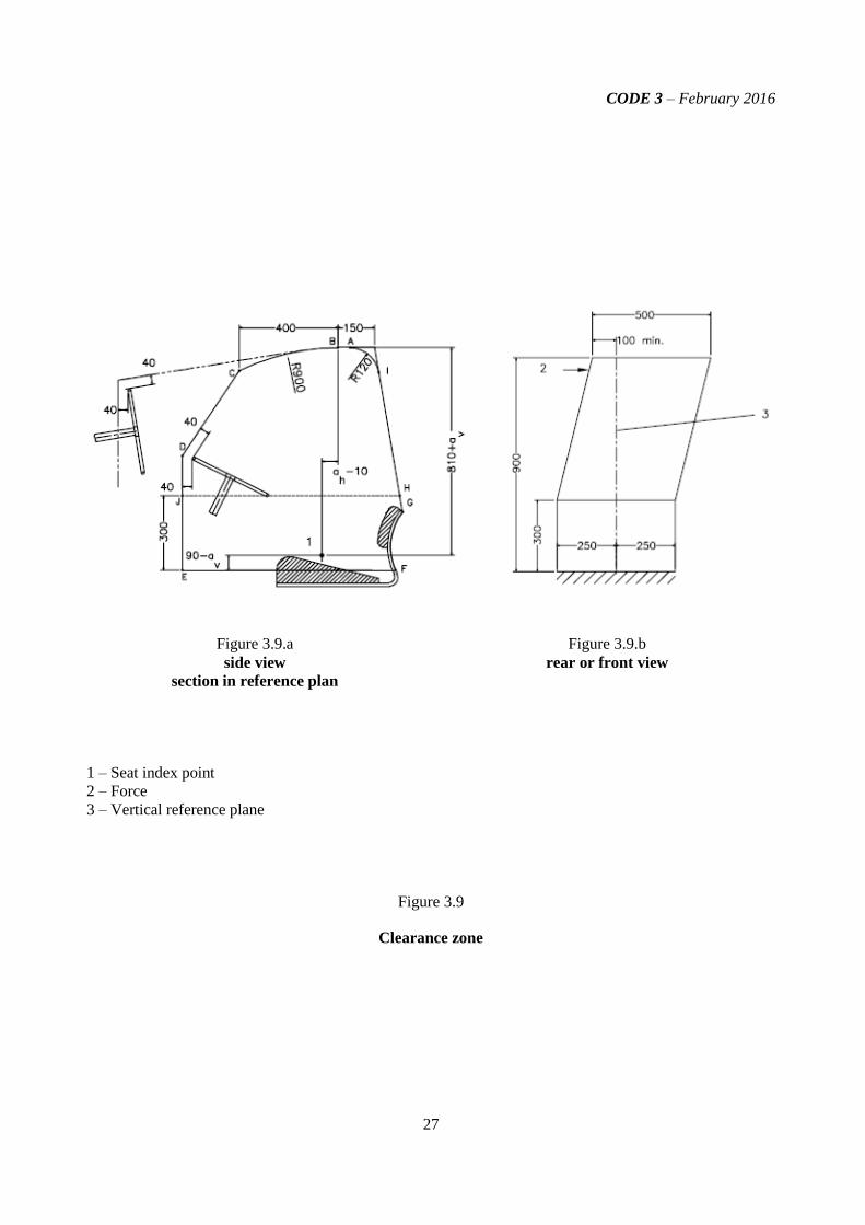
1.6.2.1 a horizontal plane A1 B1 B2 A2, (810 + av) mm above the seat index point (SIP) with line B1B2
located (ah - 10) mm behind the SIP;
1.6.2.2 an inclined plane G1 G2 I2 I1, perpendicular to the reference plane, including both a point 150
mm behind line B1B2 and the rearmost point of the seat backrest;
1.6.2.3 a cylindrical surface A1 A2 I2 I1 perpendicular to the reference plane, having a radius of 120 mm,
tangential to the planes defined in 1.6.2.1 and 1.6.2.2 above;
1.6.2.4 a cylindrical surface B1 C1 C2 B2, perpendicular to the reference plane, having a radius of 900
mm extending forward for 400 mm and tangential to the plane defined in 1.6.2.1 above along line
B1B2;
1.6.2.5 an inclined plane C1 D1 D2 C2, perpendicular to the reference plane, joining the surface defined
in 1.6.2.4 above and passing 40 mm from the forward external edge of the steering wheel. In the
case of a high steering wheel position, this plane extends forward from line B1B2 tangentially to the
surface defined in 1.6.2.4 above;
1.6.2.6 a vertical plane D1 E1 E2 D2 perpendicular to the reference plane 40 mm forward of the external
edge of the steering wheel;
1.6.2.7 a horizontal plane E1 F1 F2 E2 passing through a point (90 - av) mm below the seat index point
(SIP);
1.6.2.8 a surface G1 F1 F2 G2, if necessary curved from the bottom limit of the plane defined in 1.6.2.2
above to the horizontal plane defined in 1.6.2.7 above, perpendicular to the reference plane, and in
contact with the seat backrest throughout its length;
1.6.2.9 vertical planes J1 E1 F1 G1 H1 and J2 E2 F2 G2 H2. These vertical planes shall extend upwards
from plane E1 F1 F2 E2 for 300 mm; the distances E1 E0 and E2 E0 shall be 250 mm;
1.6.2.10 parallel planes A1 B1 C1 D1 J1 H1 I1 and A2 B2 C2 D2 J2 H2 I2 inclined so that the plane upper
edge of the plane on the side on which the force is applied is at least 100 mm from the vertical
reference plane.
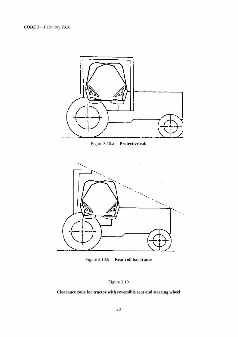
1.6.3 Determination of clearance zone for tractors with a reversible driver’s position
For tractors with a reversible driver’s position (reversible seat and steering wheel), the clearance zone
is the envelope of the two clearance zones defined by the two different positions of the steering wheel and
the seat.
2 Users are reminded that the seat index point is determined according to ISO 5353 and is a fixed point with respect to
the tractor that does not move as the seat is adjusted away from the midposition. For purposes of determining the
clearance zone, the seat shall be placed in the rear and uppermost position.
CODE 3 – February 2016
6
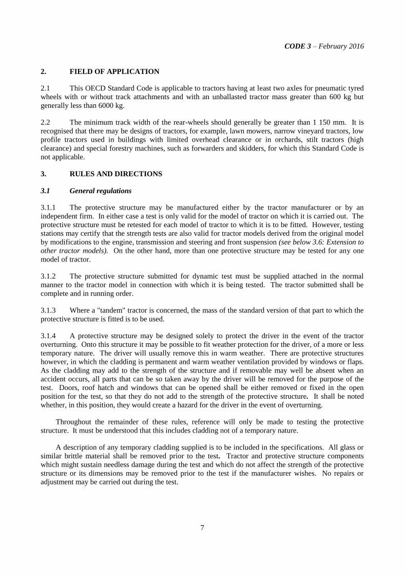
1.6.4 Optional seats
1.6.4.1 In case of tractors that could be fitted with optional seats, the envelope comprising the seat index
points of all options offered shall be used during the tests. The protective structure shall not enter the
larger clearance zone which takes account of these different seat index points.
1.6.4.2 In the case where a new seat option is offered after the test has been performed, a determination
shall be made to see whether the clearance zone around the new SIP falls within the envelope previously
established. If it does not, a new test must be performed.
1.6.4.3 Optional seat does not include a seat for a person in addition to the driver and from where the
tractor cannot be controlled. The SIP shall not be determined because the definition of the clearance zone
is in relation to the driver seat.
1.7 Unballasted mass
The mass of the tractor without ballasting devices and, in the case of tractors with pneumatic tyres,
without liquid ballast in the tyres. The tractor shall be in running order with tanks, circuits and radiator
full, protective structure with cladding and any track equipment or additional front wheel drive components
required for normal use. The operator is not included.
1.8 Permissible measurement tolerances3
Distance 0.5 mm
Force 0.1 % (of the sensor full scale)
Mass 0.2 % (of the sensor full scale)
Tyre pressure 5.0 %
Angle 0.1°
1.9 Symbols
ah (mm) Half of the horizontal seat adjustment
av (mm) Half of the vertical seat adjustment
E (J) Energy input during test
F (N) Static load force
H (mm) Height of lift of the centre of gravity of the pendulum block
I (kg.m2) Moment of inertia about rear axle, excluding wheels used
for calculating rear impact energy
L (mm) Wheelbase used for calculating rear impact energy
M (kg) Mass used for calculating energy and crushing forces
3 These “new” tolerance values should be respected excluding two particular situations:
When performing tests outside OECD Station premises, and therefore the test operators are presumably
using instrumentation set different from those normally used;
When non electronic” (i.e. mechanical or manual) measuring instruments are used. In this case, the “old”
tolerance values could be considered: Distance 0.5 %, Force 1.0 %, Mass 0.5 %.
CODE 3 – February 2016
7
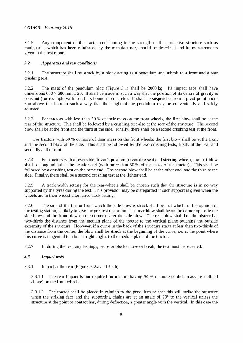
2. FIELD OF APPLICATION
2.1 This OECD Standard Code is applicable to tractors having at least two axles for pneumatic tyred
wheels with or without track attachments and with an unballasted tractor mass greater than 600 kg but
generally less than 6000 kg.
2.2 The minimum track width of the rear-wheels should generally be greater than 1 150 mm. It is
recognised that there may be designs of tractors, for example, lawn mowers, narrow vineyard tractors, low
profile tractors used in buildings with limited overhead clearance or in orchards, stilt tractors (high
clearance) and special forestry machines, such as forwarders and skidders, for which this Standard Code is
not applicable.
3. RULES AND DIRECTIONS
3.1 General regulations
3.1.1 The protective structure may be manufactured either by the tractor manufacturer or by an
independent firm. In either case a test is only valid for the model of tractor on which it is carried out. The
protective structure must be retested for each model of tractor to which it is to be fitted. However, testing
stations may certify that the strength tests are also valid for tractor models derived from the original model
by modifications to the engine, transmission and steering and front suspension (see below 3.6: Extension to
other tractor models). On the other hand, more than one protective structure may be tested for any one
model of tractor.
3.1.2 The protective structure submitted for dynamic test must be supplied attached in the normal
manner to the tractor model in connection with which it is being tested. The tractor submitted shall be
complete and in running order.
3.1.3 Where a "tandem" tractor is concerned, the mass of the standard version of that part to which the
protective structure is fitted is to be used.
3.1.4 A protective structure may be designed solely to protect the driver in the event of the tractor
overturning. Onto this structure it may be possible to fit weather protection for the driver, of a more or less
temporary nature. The driver will usually remove this in warm weather. There are protective structures
however, in which the cladding is permanent and warm weather ventilation provided by windows or flaps.
As the cladding may add to the strength of the structure and if removable may well be absent when an
accident occurs, all parts that can be so taken away by the driver will be removed for the purpose of the
test. Doors, roof hatch and windows that can be opened shall be either removed or fixed in the open
position for the test, so that they do not add to the strength of the protective structure. It shall be noted
whether, in this position, they would create a hazard for the driver in the event of overturning.
Throughout the remainder of these rules, reference will only be made to testing the protective
structure. It must be understood that this includes cladding not of a temporary nature.
A description of any temporary cladding supplied is to be included in the specifications. All glass or
similar brittle material shall be removed prior to the test. Tractor and protective structure components
which might sustain needless damage during the test and which do not affect the strength of the protective
structure or its dimensions may be removed prior to the test if the manufacturer wishes. No repairs or
adjustment may be carried out during the test.
CODE 3 – February 2016
8
3.1.5 Any component of the tractor contributing to the strength of the protective structure such as
mudguards, which has been reinforced by the manufacturer, should be described and its measurements
given in the test report.
3.2 Apparatus and test conditions
3.2.1 The structure shall be struck by a block acting as a pendulum and submit to a front and a rear
crushing test.
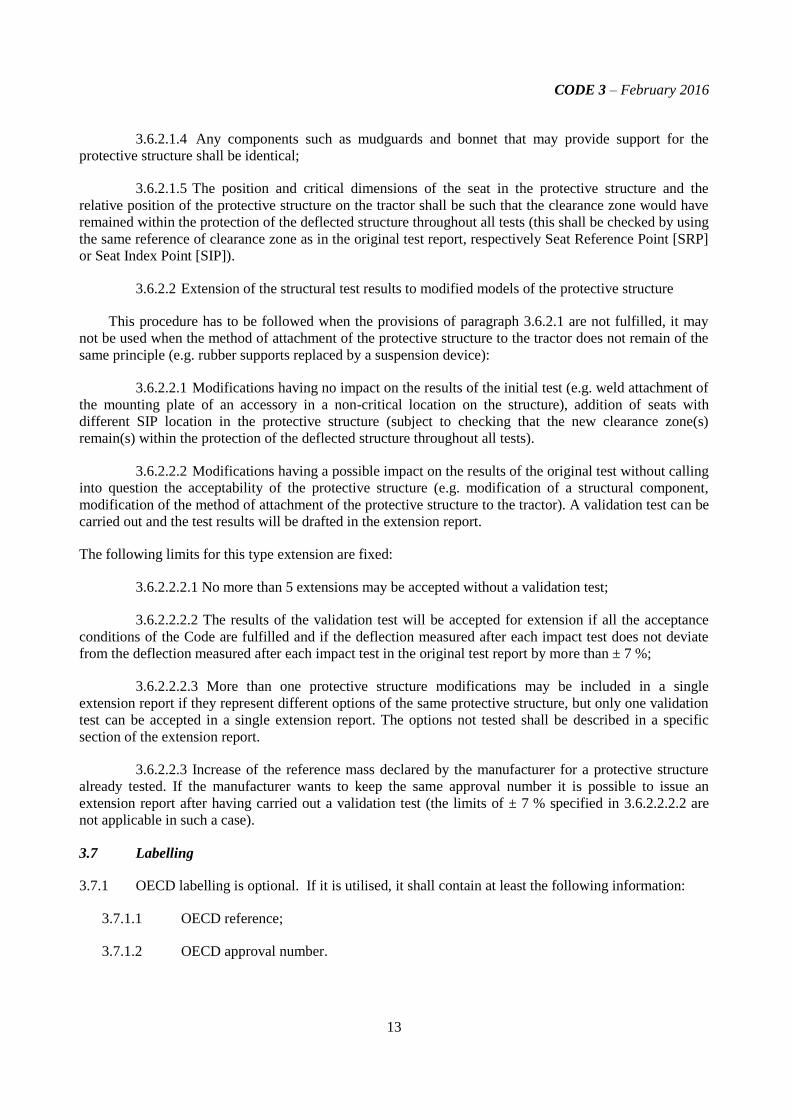
3.2.2 The mass of the pendulum bloc (Figure 3.1) shall be 2000 kg. Its impact face shall have
dimensions 680 × 680 mm ± 20. It shall be made in such a way that the position of its centre of gravity is
constant (for example with iron bars bound in concrete). It shall be suspended from a pivot point about
6 m above the floor in such a way that the height of the pendulum may be conveniently and safely
adjusted.
3.2.3 For tractors with less than 50 % of their mass on the front wheels, the first blow shall be at the
rear of the structure. This shall be followed by a crushing test also at the rear of the structure. The second
blow shall be at the front and the third at the side. Finally, there shall be a second crushing test at the front.
For tractors with 50 % or more of their mass on the front wheels, the first blow shall be at the front
and the second blow at the side. This shall be followed by the two crushing tests, firstly at the rear and
secondly at the front.
3.2.4 For tractors with a reversible driver’s position (reversible seat and steering wheel), the first blow
shall be longitudinal at the heavier end (with more than 50 % of the mass of the tractor). This shall be
followed by a crushing test on the same end. The second blow shall be at the other end, and the third at the
side. Finally, there shall be a second crushing test at the lighter end.
3.2.5 A track width setting for the rear-wheels shall be chosen such that the structure is in no way
supported by the tyres during the test. This provision may be disregarded if such support is given when the
wheels are in their widest alternative track setting.
3.2.6 The side of the tractor from which the side blow is struck shall be that which, in the opinion of
the testing station, is likely to give the greatest distortion. The rear blow shall be on the corner opposite the
side blow and the front blow on the corner nearer the side blow. The rear blow shall be administered at
two-thirds the distance from the median plane of the tractor to the vertical plane touching the outside
extremity of the structure. However, if a curve in the back of the structure starts at less than two-thirds of
the distance from the centre, the blow shall be struck at the beginning of the curve, i.e. at the point where
this curve is tangential to a line at right angles to the median plane of the tractor.
3.2.7 If, during the test, any lashings, props or blocks move or break, the test must be repeated.
3.3 Impact tests
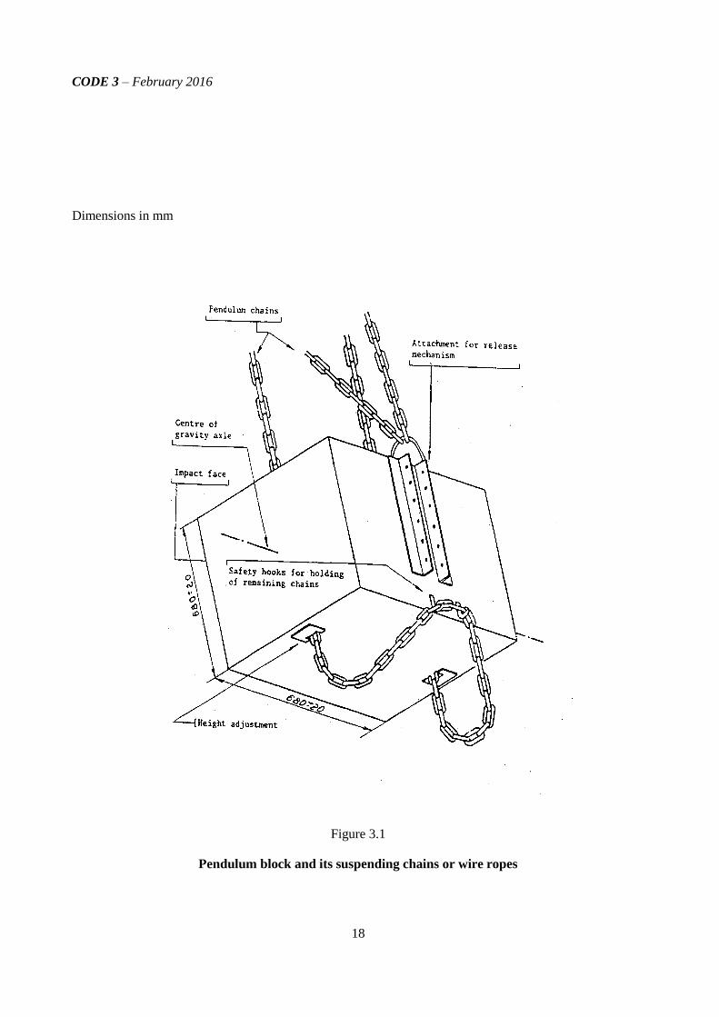
3.3.1 Impact at the rear (Figures 3.2.a and 3.2.b)
3.3.1.1 The rear impact is not required on tractors having 50 % or more of their mass (as defined
above) on the front wheels.
3.3.1.2 The tractor shall be placed in relation to the pendulum so that this will strike the structure
when the striking face and the supporting chains are at an angle of 20° to the vertical unless the
structure at the point of contact has, during deflection, a greater angle with the vertical. In this case the

CODE 3 – February 2016
9
striking face shall be adjusted parallel to the side of the structure at the point of contact at the moment
of maximum deflection by an additional support, the supporting chains remaining at an angle of 20° to
the vertical. The point of impact shall be that part of the structure likely to hit the ground first in a
rearward overturning accident, normally the upper edge. The height of the pendulum will be so
adjusted that it has no tendency to turn about the point of contact.
3.3.1.3 The tractor will be lashed down. The points of attachment of the lashings shall be
approximately 2 m behind the rear axle and 1.5 m in front of the front axle. There shall be two
lashings on each axle, one on each side of the median plane of the tractor. The lashings shall be steel
cable of 12.5 to 15 mm diameter, tensile strength 1100 - 1260 MPa. The tyres of the tractor shall be
inflated, and the lashings tightened to give tyre pressures and deflections, as shown in the Table 3.1,
below.
After the lashings have been tightened a wood beam 150 x 150 mm shall be clamped in front of the
rear-wheels, driven tight against them.
3.3.1.4 The pendulum shall be pulled back so that the height H of its centre of gravity above that at
the point of impact is given by one of the following formulae at the option of the manufacturer:
H = 2.165 x 10⁻⁸
ML2 or H = 5.73 x 10
-2 I
3.3.1.5 The pendulum shall be released and allowed to crash against the structure. The quick release
mechanism must be so positioned that it does not tilt the weight in relation to the chains supporting it at
the moment of release.
Tyre pressures
kPa (*)
Deflection
mm
Four-wheel drive tractors with front and rear wheels of the same size:
Front 100 25
Rear 100 25
Four-wheel drive tractors with front wheels smaller than rear wheels:
Front 150 20
Rear 100 25
Two-wheel drive tractors:
Front 200 15
Rear 100 25
(*) No water ballast is to be used
Table 3.1
Tyre Pressures
3.3.2 Impact at the front (Figures 3.3.a and 3.3.b)
3.3.2.1 This shall be carried out in the same way as the impact at the rear. The lashings shall be the
same but the wooden beam shall be behind the rear-wheels. The height of fall of the centre of gravity
of the pendulum shall be given by the following formula:

CODE 3 – February 2016
10
H = 125 + 0.02 M
3.3.2.2. The point of impact shall be that part of the structure that would hit the ground first when
turning over sideways while travelling forward, normally the top of the front corner.
3.3.3 Impact at the side (Figure 3.4)
3.3.3.1 The tractor shall be placed in relation to the pendulum so that this will strike the structure
when the striking face and the supporting chains are vertical unless the structure at the point of contact
is, during deflection, other than vertical. In this case the striking face shall be adjusted so that it is
approximately parallel to the structure at the point of contact at the moment of maximum deflection.
This adjustment shall be made by an additional support, the supporting chains remaining vertical at the
moment of impact. The point of impact shall be that part of the structure likely to hit the ground first in
a sideways overturning accident, normally the upper edge.
3.3.3.2 Unless it is certain that any other part of this edge would hit the ground first, the point of
impact shall be in the plane at right angles to the median plane of the tractor and passing 60 mm in
front of the seat index point, the seat being at its mid-point of longitudinal adjustment. The height of
the pendulum will be so adjusted that it has no tendency to turn about the point of contact.
3.3.3.3 For tractors with a reversible driver’s position, the point of impact shall be in the plane at
right angles to the median plane of the tractor and at the mid-point between the two seat index points.
3.3.3.4 The rear-wheel of the tractor on the side to be struck shall be lashed down. The tension in the
lashings shall be determined as for the impact at the rear. After lashing, a beam 150 x 150 mm shall be
clamped against the side of the rear-wheel opposite the blow, and driven hard against the tyre. A beam
shall be placed as a prop against this wheel and secured on the floor so that it is held tight against the
wheel during impact. The length of this beam shall be chosen so that when in position against the
wheel it makes an angle of 25 to 40° with the horizontal. Furthermore its length shall be 20 to 25 times
its thickness and its width 2 to 3 times its thickness.
3.3.3.5 The pendulum shall be pulled back as in the previous tests so that the height H of its centre of
gravity above that at the moment of impact is determined by the following formula:
H = 125 + 0.15 M.
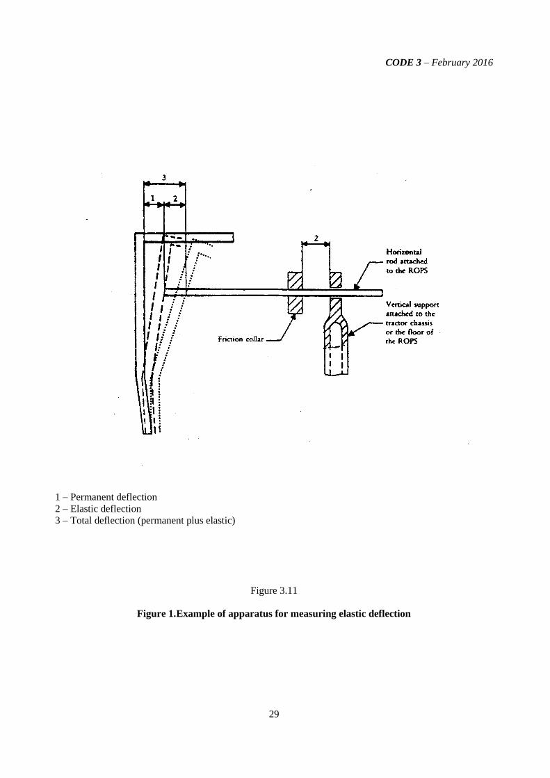
3.3.3.6 During the side impact test the difference between the maximum momentary deflection and
the residual deflection at a height of (810 + av) mm above the seat index point shall be recorded. This
may be done with a device on which a moving friction collar shall be fitted on a horizontal rod. One
end of the rod shall be attached to the top member of the structure and the other will pass through a
hole in a vertical bar attached to tractor chassis. The collar will be positioned against the vertical bar
attached to tractor chassis before the blow and its distance from it after the blow will give the
difference between the maximum momentary deflection and the residual deflection.
3.4 Crushing tests
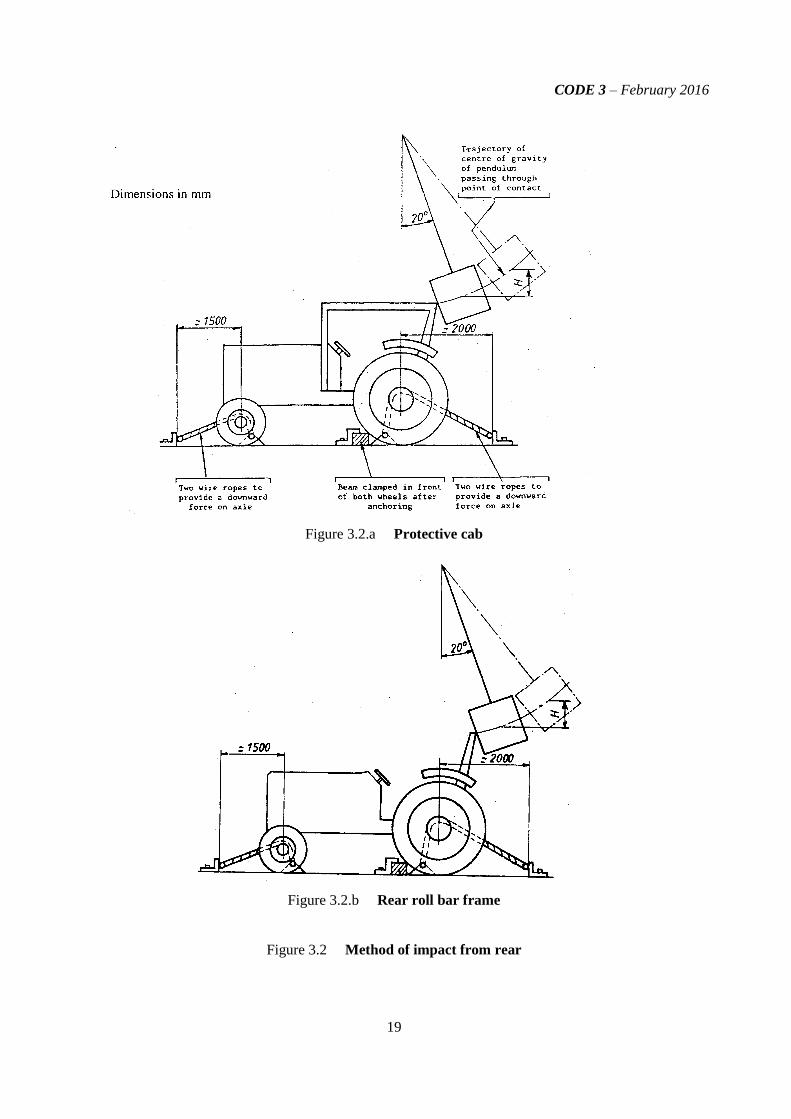
It may be necessary to hold down the front of the tractor when carrying out the test at the rear. Blocks
will be placed under the axles so that the tyres do not bear crushing force. The cross beam used shall have
a width of approximately 250 mm and shall be connected to the load applying mechanism by universal
joints (Figure 3.5).
3.4.1 Crushing at the rear (Figures 3.6.a and 3.6.b)

CODE 3 – February 2016
11
3.4.1.1 The crushing beam shall be positioned across the rear uppermost structural members so that
the resultant of the crushing forces is located in the vertical reference plane of the tractor. The crushing
force (F) shall be applied where:
F = 20 M.
This force shall be maintained for 5 seconds after cessation of any visually detectable movement
of the protective structure.
3.4.1.2 Where the rear part of the protective structure roof will not sustain the full crushing force
(Figures 3.7.a and 3.7.b), the force shall be applied until the roof is deflected to coincide with the plane
joining the upper part of the protective structure with that part of the rear of the tractor capable of
supporting the tractor when overturned.
The force shall then be removed and the crushing beam repositioned over that part of the
protective structure that would support the tractor when completely overturned. The crushing force F
shall be applied.
3.4.2 Crushing at the front (Figures 3.6.a and 3.6.b)
3.4.2.1 The crushing beam shall be positioned across the front uppermost structural members so that
the resultant of the crushing forces is located in the vertical reference plane of the tractor. The crushing
force (F) shall be applied where:
F = 20 M.
This force shall be maintained for 5 seconds after cessation of any visually detectable movement
of the protective structure.
3.4.2.2 When the front part of the roof of the protective structure will not sustain the full crushing
force (Figures 3.7.a and 3.7.b), the force shall be applied until the roof is deflected to coincide with the
plane joining the upper part of the protective structure with that part of the front of the tractor capable
of supporting the tractor when overturned.
The force shall then be removed and the crushing beam repositioned over that part of the
protective structure that would support the tractor when completely overturned. The crushing force F
shall then be applied.
3.5 Conditions for acceptance
3.5.1 The structure and tractor shall be visually examined for cracks and tears after each part of the
test. For the structure to pass the test the following conditions shall be complied with:
3.5.1.1 there shall be no cracks in structural members, mounting components or tractor parts
contributing to the strength of the protective structure (except as covered by 3.5.1.3 below);
3.5.1.2 there shall be no cracks in welds contributing to the strength of the protective structure or its
mounting components. Spot or tack welding used for the attachment of cladding panels shall normally
be excluded from this condition;

CODE 3 – February 2016
12
3.5.1.3 energy-absorbing tears in sheet metal structures are acceptable, providing that they are judged
by the testing station to have not significantly reduced the resistance to deflection of the protective
structure. Tears in sheet metal components caused by edges of the pendulum weight shall be ignored;
3.5.1.4 the required force must be sustained in both crushing tests;
3.5.1.5 the difference between the maximum momentary deflection and the residual deflection in the
side impact test must not exceed 250 mm (Figure 3.11);
3.5.1.6 no part shall enter the clearance zone during any part of the tests. No part may strike the seat
during the tests. Furthermore, the clearance zone shall not be outside the protection of the protective
structure. For this purpose, it shall be considered to be outside the protection of the structure if any
part of it would come in contact with flat ground if the tractor overturned towards the direction from
which the test load is applied. For estimating this, the tyres and track width setting shall be the
smallest standard fitting specified by the manufacturer.
3.5.1.7 for the articulated tractors, the median planes of the two parts shall be assumed to be in line.
3.5.2 After the final crushing test, the permanent deformation of the protective structure shall be
recorded. For this purpose, before the start of the test, the position of the main members in relation to the
seat index point must be recorded. Then any movement of the members struck in the tests and any change
of the height of the front and back members of the roof shall be recorded.
3.6 Extension to other tractor models
3.6.1 Administrative extension
If there are changes in the make, denomination or marketing features of the tractor or protective
structure tested or listed in the original test report, the testing station that has carried out the original test
can issue an ‘’administrative extension report’’. This extension report shall contain a reference to the
original test report.
3.6.2 Technical extension
When technical modifications occur on the tractor, the protective structure or the method of
attachment of the protective structure to the tractor, the testing station that has carried out the original test
can issue a “technical extension report” in the following cases:
3.6.2.1 Extension of the structural test results to other models of tractors
The impact and crushing tests need not be carried out on each model of tractor, provided that the
protective structure and tractor comply with the conditions referred to hereunder 3.6.2.1.1 to 3.6.2.1.5.
3.6.2.1.1 The structure shall be identical to the one tested;
3.6.2.1.2 The required energy shall not exceed the energy calculated for the original test by more
than 5 %. The 5 % limit shall also apply to extensions in the case of substituting tracks for wheels on the
same tractor;
3.6.2.1.3 The method of attachment and the tractor components to which the attachment is made
shall be identical;
CODE 3 – February 2016
13
3.6.2.1.4 Any components such as mudguards and bonnet that may provide support for the
protective structure shall be identical;
3.6.2.1.5 The position and critical dimensions of the seat in the protective structure and the
relative position of the protective structure on the tractor shall be such that the clearance zone would have
remained within the protection of the deflected structure throughout all tests (this shall be checked by using
the same reference of clearance zone as in the original test report, respectively Seat Reference Point [SRP]
or Seat Index Point [SIP]).
3.6.2.2 Extension of the structural test results to modified models of the protective structure
This procedure has to be followed when the provisions of paragraph 3.6.2.1 are not fulfilled, it may
not be used when the method of attachment of the protective structure to the tractor does not remain of the
same principle (e.g. rubber supports replaced by a suspension device):
3.6.2.2.1 Modifications having no impact on the results of the initial test (e.g. weld attachment of
the mounting plate of an accessory in a non-critical location on the structure), addition of seats with
different SIP location in the protective structure (subject to checking that the new clearance zone(s)
remain(s) within the protection of the deflected structure throughout all tests).
3.6.2.2.2 Modifications having a possible impact on the results of the original test without calling
into question the acceptability of the protective structure (e.g. modification of a structural component,
modification of the method of attachment of the protective structure to the tractor). A validation test can be
carried out and the test results will be drafted in the extension report.
The following limits for this type extension are fixed:
3.6.2.2.2.1 No more than 5 extensions may be accepted without a validation test;
3.6.2.2.2.2 The results of the validation test will be accepted for extension if all the acceptance
conditions of the Code are fulfilled and if the deflection measured after each impact test does not deviate
from the deflection measured after each impact test in the original test report by more than ± 7 %;
3.6.2.2.2.3 More than one protective structure modifications may be included in a single
extension report if they represent different options of the same protective structure, but only one validation
test can be accepted in a single extension report. The options not tested shall be described in a specific
section of the extension report.
3.6.2.2.3 Increase of the reference mass declared by the manufacturer for a protective structure
already tested. If the manufacturer wants to keep the same approval number it is possible to issue an
extension report after having carried out a validation test (the limits of ± 7 % specified in 3.6.2.2.2.2 are
not applicable in such a case).
3.7 Labelling
3.7.1 OECD labelling is optional. If it is utilised, it shall contain at least the following information:
3.7.1.1 OECD reference;
3.7.1.2 OECD approval number.

CODE 3 – February 2016
14
3.7.2 The label shall be durable and permanently attached to the protective structure such that it can be
easily read and it shall be protected from environmental damage.
3.8 Cold weather performance of protective structures
3.8.1 If the protective structure is claimed to have properties resistant to cold weather embrittlement,
the manufacturer shall give details that shall be included in the report.
3.8.2 When applicable, cold weather embrittlement properties shall be verified either in accordance
with the requirements given in 3.8.2.1 to 3.8.2.7 or alternatively by 3.8.3.
Specimen size Energy at Energy at
-30 °C -20 °C
mm J Jb)
10 x 10a)
11 27.5
10 x 9 10 25
10 x 8 9.5 24
10 x 7,5a)
9.5 24
10 x 7 9 22.5
10 x 6.7 8.5 21
10 x 6 8 20
10 x 5a) 7.5 19
10 x 4 7 17.5
10 x 3.5 6 15
10 x 3 6 15
10 x 2.5a) 5.5 14
Table 3.2
Minimum Charpy V-notch impact energies
a) Indicates preferred size. Specimen size shall be no less than largest preferred size that the material permits.
b) The energy requirement at – 20 °C is 2.5 times the value specified for –30 °C. Other factors affect impact energy
strength, i.e. direction of rolling, yield strength, grain orientation and welding. These factors shall be considered
when selecting and using steel.
3.8.2.1 Bolts and nuts used to attach the protective structure to the tractor and used to connect
structural parts of the protective structure shall exhibit suitable controlled reduced temperature
toughness properties.
3.8.2.2 All welding electrodes used in the fabrication of structural members and mounts shall be
compatible with the protective structure material as given in 3.8.2.3 below.

CODE 3 – February 2016
15
3.8.2.3 Steel materials for structural members of the protective structure shall be of controlled
toughness material exhibiting minimum Charpy V-Notch impact energy requirements as shown in
Table 3.2. Steel grade and quality shall be specified in accordance with ISO 630:1995; Amd1:2003.
Steel with an as-rolled thickness less than 2.5 mm and with a carbon content less than 0.2 % is
considered to meet this requirement. Structural members of the protective structure made from
materials other than steel shall have equivalent low temperature impact resistance.
3.8.2.4 When testing the Charpy V-Notch impact energy requirements, the specimen size shall be no
less than the largest of the sizes stated in Table 3.2 that the material will permit.
3.8.2.5 The Charpy V-Notch tests shall be made in accordance with the procedure in
ASTM A 370-1979, except for specimen sizes that shall be in accordance with the dimensions given in
Table 3.2.
3.8.2.6 Alternatives to this procedure are the use of killed or semi-killed steel for which an adequate
specification shall be provided. Steel grade and quality shall be specified in accordance with ISO
630:1995; Amd1:2003.
3.8.2.7 Specimens are to be longitudinal and taken from flat stock, tubular or structural sections
before forming or welding for use in the protective structure. Specimens from tubular or structural
sections are to be taken from the middle of the side of greatest dimension and shall not include welds.
3.8.3 Resistance to cold weather embrittlement may be demonstrated by applying this code at a
reduced temperature of -18°C or colder. Prior to testing the protective structure and all mounting hardware
shall be cooled to -18° C or colder prior to beginning the dynamic test.
3.9 Seatbelt anchorage performance (Optional)
3.9.1 Scope
Seat belts are one of the operator restraint systems used for securing the driver in motor vehicles.
This recommended procedure provides minimum performance and tests requirements for anchorage
for agricultural and forestry tractors.
It applies to the anchorage of pelvic restraint systems.
3.9.2 Explanation of terms used in the performance testing
3.9.2.1 The seat belt assembly is any strap or belt device fastened across the lap or pelvic girdle area
designed to secure a person in a machine.
3.9.2.2 The extension belt is intended as any strap, belt, or similar device that aids in the transfer of
seat belt loads.
3.9.2.3 The anchorage is intended as the point where the seat belt assembly is mechanically attached
to the seat system or tractor.
3.9.2.4 The seat mounting is intended as all intermediary fittings (such as slides, etc.) used to secure
the seat to the appropriate part of the tractor.

CODE 3 – February 2016
16
3.9.2.5 The Operator Restraint System is intended as the total system composed of seat belt
assembly, seat system, anchorages and extension which transfers the seat belt load to the tractor.
3.9.2.6 Applicable Seat Components comprise all components of the seat whose mass could
contribute to loading of the seat mounting (to the vehicle structure) during a roll-over event.
3.9.3 Test procedure
The procedure is applicable to a seat belt anchorage system provided for a driver or a person in
addition to the driver carried by the tractor.
Only static tests for anchorages are given in this procedure.
If, for a given protective structure, a manufacturer provides more than one seat with identical
components which transfer the load from the seatbelt anchorage to the seat mounting on the ROPS floor
or tractor chassis, the Testing Station is authorized to test only one configuration, corresponding to the
heaviest seat (see also below).
The seat shall be in position during the tests and fixed to the mounting point on the tractor using all
intermediary fittings (such as suspension, slides, etc.) specified for the complete tractor. No additional non-
standard fittings contributing to the strength of the construction may be used.
The worst case loading scenario for seat belt anchorage performance testing should be identified with
consideration to the following points:-
If the masses of alternative seats are comparable, those featuring seat belt anchorages which transfer
loading through the seat structure (e.g. via the suspension system and/or adjustment slides), will be
required to withstand much higher test loading. They are therefore likely to represent the worst
case;
If the applied loading will pass through the seat mountings to the vehicle chassis, the seat should be
adjusted longitudinally to achieve the minimum amount of overlap of the mounting slides / rails.
This will usually be when the seat is in the fully-rearward position but, if certain vehicle installations
limit seat rearward travel, the fully-forward seat position may provide the worst case loading
position. Observation of the amount of seat movement and mounting slide / rail overlap is required
The anchorages shall be capable of withstanding the loads applied to the seat belt system using a
device as shown in Figure 3.12. The seat belt anchorages shall be capable of these test loads applied with
the seat adjusted in the worst position of the longitudinal adjustment to ensure that the test condition is met.
The test loads shall be applied with the seat in the mid-position of the longitudinal adjustment if a worst
position among the possible seat adjustments is not recognised by the testing station. For a suspended seat,
the seat shall be set to the midpoint of the suspension travel, unless this is contradictory to a clearly stated
instruction by the seat manufacturer. Where special instructions exist for the seat setting, these shall be
observed and specified in the report. After the load is applied to the seat system, the load application
device shall not be repositioned to compensate for any changes that may occur to the load application
angle.
3.9.3.1 Forward loading

CODE 3 – February 2016
17
A tensile force shall be applied in a forward and upward direction at an angle of 45º ± 2º to the
horizontal, as shown in Figure 3.13. The anchorages shall be capable of withstanding a force of
4 450 N. In the event that the force applied to the seat belt assembly is transferred to the vehicle
chassis by means of the seat, the seat mounting shall be capable of withstanding this force plus an
additional force equal to four times the force of gravity on the mass of all applicable seat components,
applied 45º ± 2º to the horizontal in a forward and upward direction, as shown in Figure 3.13.
3.9.3.2 Rearward loading
A tensile force shall be applied in a rearward and upward direction at an angle of 45º ± 2º to the
horizontal, as shown in Figure 3.14. The anchorages shall be capable of withstanding a force of
2 225 N. In the event that the force applied to the seat belt assembly is transferred to the vehicle
chassis by means of the seat, the seat mounting shall be capable of withstanding this force plus an
additional force equal to two times the force of gravity on the mass of all applicable seat components,
applied 45º ± 2º to the horizontal in a rearward and upward direction, as shown in Figure 3.14.
Both tensile forces shall be equally divided between the anchorages.
3.9.3.3 Seatbelt buckle release force (if required by the manufacturer)
The seat belt buckle shall open with a maximum force of 140 N following the load applications.
This requirement is fulfilled for seat belt assemblies that satisfy the requirements of UN-ECE R-16 or
Directive 77/541/EEC as last amended.
3.9.4 Test result
Condition of acceptance
Permanent deformation of any system component and anchorage area is acceptable under the action
of the forces specified in 3.9.3.1 and 3.9.3.2. However, there shall be no failure allowing release of the
seat belt system, seat assembly, or the seat adjustment locking mechanism.
The seat adjuster or locking device need not be operable after application of the test load.
The results of a test performed on an identical “operator restraint system” may be included in more
than one test report provided that this system is fitted exactly in the same conditions.
The results of a test performed after the approval of the test report of the protective structure shall be
drafted in a technical extension report.
CODE 3 – February 2016
18
Dimensions in mm
Figure 3.1
Pendulum block and its suspending chains or wire ropes
CODE 3 – February 2016
19
Figure 3.2.a Protective cab
Figure 3.2.b Rear roll bar frame
Figure 3.2 Method of impact from rear

CODE 3 – February 2016
20
Figure 3.30.a Protective cab
Figure 3.3.b Rear roll bar frame
Figure 3.3 Method of impact from front

CODE 3 – February 2016
21
Figure 3.4
Method of impact from side
CODE 3 – February 2016
22
Figure 3.5
Example of an arrangement for crushing tests

CODE 3 – February 2016
23
Figure 3.6.a Protective cab
Figure 3.6.b Rear roll bar frame
Figure 3.6
Position of beam for front and rear crushing tests

CODE 3 – February 2016
24
Figure 3.7.a Protective cab
Figure 3.7.b Rear roll bar frame
Figure 3.7
Position of beam for front crushing test
when full crushing force not sustained in front
CODE 3 – February 2016
25
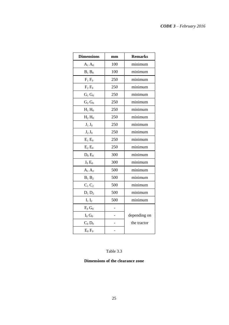
Dimensions mm Remarks
A1 A0 100 minimum
B1 B0 100 minimum
F1 F0 250 minimum
F2 F0 250 minimum
G1 G0 250 minimum
G2 G0 250 minimum
H1 H0 250 minimum
H2 H0 250 minimum
J1 J0 250 minimum
J2 J0 250 minimum
E1 E0 250 minimum
E2 E0 250 minimum
D0 E0 300 minimum
J0 E0 300 minimum
A1 A2 500 minimum
B1 B2 500 minimum
C1 C2 500 minimum
D1 D2 500 minimum
I1 I2 500 minimum
F0 G0 -
I0 G0 - depending on
C0 D0 - the tractor
E0 F0 -
Table 3.3
Dimensions of the clearance zone

CODE 3 – February 2016
26
1 – Seat index point
Figure 3.8
Clearance zone
Note: for dimensions, see Table 3.3 above
CODE 3 – February 2016
27
Figure 3.9.a
side view
section in reference plan
Figure 3.9.b
rear or front view
1 – Seat index point
2 – Force
3 – Vertical reference plane
Figure 3.9
Clearance zone
CODE 3 – February 2016
28
Figure 3.10.a Protective cab
Figure 3.10.b Rear roll bar frame
Figure 3.10
Clearance zone for tractor with reversible seat and steering wheel
CODE 3 – February 2016
29
1 – Permanent deflection
2 – Elastic deflection
3 – Total deflection (permanent plus elastic)
Figure 3.11
Figure 1. Example of apparatus for measuring elastic deflection

CODE 3 – February 2016
30
Figure 3.12
The load application device
Note: The dimensions not shown are optional to satisfy the test facility and do not influence the test results

CODE 3 – February 2016
31
Figure 3.13
Load application in the upward and forward direction
Figure 3.14
Load application in the upward and rearward direction

CODE 3 – February 2016
32
SPECIMEN TEST REPORT
Note: Units shown below, which appear in ISO 1000:1992; Amd1:1998, shall be stated and followed by
national units in parentheses, if necessary.
Protective structure manufacturer’s name and address:
Submitted for test by:
Make of the protective structure:
Model of the protective structure:
Type of the protective structure: Cab, Frame, Rear rollbar, Cab with integrated frame, etc.
Date, location of test and Code version:
1. SPECIFICATION OF TEST TRACTOR
1.1 Identification of tractor to which the protective structure is fitted for the test
1.1.1 - Make of the tractor: (*)
- Model (trade name):
- Type: 2 WD or 4 WD; rubber or steel tracks (if applicable);
articulated 4 WD or articulated 4 WD with twin (dual) wheels (if applicable)
(*) possibly different from tractor manufacturer's name
1.1.2 Numbers
- 1st Serial No. or prototype:
- Serial No.:
1.2 Mass of unballasted tractor with protective structure fitted and without driver
Front kg
Rear kg
Total kg
- Mass used for calculating impact energies and crushing forces: kg
1.3 Wheelbase and moment of inertia
- Wheelbase of test tractor: mm
- Moment of inertia used for calculating impact energy at the rear: kg.m2
1.4 Minimum track and tyre sizes
Minimum track Tyre sizes
Front mm

CODE 3 – February 2016
33
Rear mm
1.5 Tractor seat
- Tractor with a reversible driver’s position (reversible seat and steering wheel): Yes / No
- Make/ type/ model of driver’s seat:
- Make/ type/ model of optional seat(s)
and position(s) of the seat index point (SIP) (only for driver seats):
(description of seat 1 and SIP position)
(description of seat 2 and SIP position)
(description of seat __ and SIP position)
- Seat belt anchorage: Type
- Seat mounting on the tractor: Type
- Other seat components: Type
- Seat operating position in the test: Description
Masses used for calculating the loads
Seat Make/Model/Type
COMPONENTS MASS (kg)
Driver seat:
Seat belt assembly:
Other seat components:
Total:
2. SPECIFICATION OF PROTECTIVE STRUCTURE
2.1 Photographs from side and rear showing mounting details including mudguards
2.2 General arrangement drawing of the side and the rear of the structure including position of
the seat index points (SIP), details of mountings and position of the front part of the tractor capable of
supporting the tractor when overturned (if necessary).
2.3 Brief description of the protective structure comprising:
-- type of construction;
-- details of mountings;
-- details of cladding and padding;
-- details of the front part of the tractor capable of supporting the tractor when overturned (if
necessary)
-- means of access and escape;
-- additional frame: Yes / No
2.4 Tiltable / not tiltable structure

CODE 3 – February 2016
34
-- Tiltable / not tiltable (*)
If it is necessary to tilt with any tools, this should be stated as follows:
-- Tiltable with tools/ tiltable without tools (*)
-- Folding/ not folding (*)
If it is necessary to fold with any tools, this should be stated as follows:
-- Folding with tools/ folding without tools (*)
(*) delete as appropriate
2.5 Dimensions
Dimensions should be measured with seatpan and backrest loaded and adjusted according to
Definition 1.5 of the Code.
When the tractor is fitted with different optional seats or has a reversible driver’s position (reversible
seat and steering wheel), the dimensions in relation to the seat index points shall be measured in each case
(SIP 1, SIP 2, etc.).
2.5.1 Height of roof members above the seat index point: mm
2.5.2 Height of roof members above the tractor footplate: mm
2.5.3 Interior width of the protective structure
(810 + av) mm above the seat index point: mm
2.5.4 Interior width of the protective structure vertically above the
seat index point at the level of centre of the steering wheel: mm
2.5.5 Distance from the centre of the steering wheel
to the right-hand side of the protective structure: mm
2.5.6 Distance from the centre of the steering wheel
to the left-hand side of the protective structure: mm
2.5.7 Minimum distance from the steering wheel rim to the protective structure: mm
2.5.8 Horizontal distance from the seat index point to the rear of
the protective structure at a height of (810 + av) mm above the seat index point: mm
2.5.9 Position (with reference to the rear axle) of the front part of tractor capable of
supporting the tractor when overturned:
horizontal distance: mm
vertical distance: mm
2.6 Details of materials used in the construction of the protective structure
and specifications of steels used
Steel specifications shall be in conformity with ISO 630:1995; Amd1:2003.

CODE 3 – February 2016
35
2.6.1 Main frame: (parts - material - sizes)
Is steel rimmed, semi-killed or killed:
steel standard and reference:
2.6.2 Mountings: (parts - material - sizes)
Is steel rimmed, semi-killed or killed:
steel standard and reference:
2.6.3 Assembly and mounting bolts: (parts - sizes)
2.6.4 Roof : (parts - material - sizes)
2.6.5 Cladding: (parts - material - sizes)
2.6.6 Glass: (type - grade - sizes)
2.6.7 Front part of the tractor capable of supporting the tractor
when overturned (if necessary) (parts - material - sizes)
2.7. Details of tractor manufacturer's reinforcements on original parts
3. TEST RESULTS
3.1 Impact and crushing tests
3.1.1 Condition of tests
- Impact tests were made:
to the rear left / right
to the front right / left
to the side right / left
- Mass used for calculating impact energies and crushing forces: kg
- Wheelbase used for calculating impact energy at the rear: mm
- Moment of inertia used for calculating impact energy at the rear: kgm2
- Energies and forces applied:
rear: kJ
front: kJ
side: kJ
crushing force: kN
3.1.2 Permanent deflections measured after the tests
3.1.2.1 Permanent deflections of the extremities of the protective structure measured after the series
of tests:
- Back (forwards / backwards):
left-hand: mm
right-hand: mm
- Front (forwards / backwards):
left-hand: mm
CODE 3 – February 2016
36
right-hand: mm
- Sideways (to the left / to the right):
front: mm
rear: mm
- Top (downwards / upwards):
rear: left-hand: mm
right-hand: mm
front: left-hand: mm
right-hand: mm
3.1.2.2 Difference between total instantaneous deflection and
residual deflection during sideways impact test (elastic deflection): mm
Statement:
The acceptance conditions of these tests relative to the protection of the clearance zone are
fulfilled. The structure is a roll-over protective structure in accordance with the Code.
3.2 Cold weather performance (resistance to brittle fracture)
Method used to identify resistance to brittle fracture at reduced temperature:
.
.
.
Steel specifications shall be in conformity with ISO 630:1995; Amd1:2003.
Steel specification: (reference and relevant standard)

CODE 3 – February 2016
37
3.3 Seatbelt anchorage performance
3.3.1 Loading in the forward and upward direction
Driver seat make/model/type
GRAVITY FORCE
(Fg = seat mass x 9.81)
N
REQUIRED FORCE
(4450 + 4Fg)
N
APPLIED FORCE
N
3.3.2. Loading in the rearward and upward direction
Driver seat make/model/type
GRAVITY FORCE
(Fg = seat mass x 9.81)
N
REQUIRED FORCE
(2225 + 2Fg)
N
APPLIED FORCE
N
3.3.3 Curves, drawings and photos
A copy of the force/deflection curves derived during the tests shall be included.
Drawings and/or photos of the seat mounting and anchorages have to be added.
Statement (if necessary):
The testing station certifies that the tested seat is the worst variant among the seats listed below
that are identical regarding the seatbelt anchorage performance test.
Statement:
During the test, no structural failure or release of seat, seat adjuster mechanism or other
locking service occurred. The seat and safety belt anchorage tested fulfil the requirement of the
OECD procedure.
3.4 Tractor(s) to which the protective structure is fitted
OECD Approval Number :
Make Model Type Other
specifi-
cations
Mass Tiltable Wheel-
Base
Minimum track
Front Rear Total Front Rear
2/4 WD,
etc
where
applicable
kg kg kg Yes/ No mm mm

CODE 3 – February 2016
38
SPECIMEN TECHNICAL EXTENSION REPORT
Note: Units shown below, which appear in ISO 1000:1992; Amd1:1998, shall be stated and followed by
national units in parentheses, if necessary.
Protective structure manufacturer’s name and address:
Submission for extension by:
Make of the protective structure:
Model of the protective structure:
Type of the protective structure: Cab, Frame, Rear rollbar, Cab with integrated frame, etc.
Date, location of extension and Code version:
Reference of the original test:
Approval number and date of the original test report:
Statement giving the reasons of the extension and explaining the procedure chosen (e.g. extension with
validation test):
Depending on the case some of the following paragraphs may be omitted if their content is identical to the
one of the original test report. It is only necessary to highlight the differences between the tractor and
protective structure described in the original test report and the one for which the extension has been
required.
1. SPECIFICATION OF TEST TRACTOR
1.1 Identification of tractor to which the protective structure is fitted for the test
1.1.1 - Make of the tractor: (*)
- Model (trade name):
- Type: 2 WD or 4 WD; rubber or steel tracks (if applicable);
articulated 4 WD or articulated 4 WD with twin (dual) wheels (if applicable)
(*) possibly different from tractor manufacturer's name
1.1.2 Numbers
- 1st Serial No. or prototype:
- Serial No.:

CODE 3 – February 2016
39
1.2 Mass of unballasted tractor with protective structure fitted and without driver
Front kg
Rear kg
Total kg
- Mass used for calculating impact energies and crushing forces: kg
1.3 Wheelbase and moment of inertia
- Wheelbase of test tractor: mm
- Moment of inertia used for calculating impact energy at the rear: kgm2
1.4 Minimum track and tyre sizes
Minimum track Tyre sizes
Front mm
Rear mm
1.5 Tractor seat
- Tractor with a reversible driver’s position (reversible seat and steering wheel): Yes / No
- Make/ type/ model of driver’s seat:
- Make/ type/ model of optional seat(s)
and position(s) of the seat index point (SIP) (only for driver seats) :
(description of seat 1 and SIP position)
(description of seat 2 and SIP position)
(description of seat __ and SIP position)
- Seat belt anchorage: Type
- Seat mounting on the tractor: Type
- Other seat components: Type
- Seat operating position in the test: Description
Masses used for calculating the loads
Seat Make/Model/Type
COMPONENTS MASS (kg)
Driver seat:
Seat belt assembly:
Other seat components:
Total:

CODE 3 – February 2016
40
2. SPECIFICATION OF PROTECTIVE STRUCTURE
2.1 Photographs from side and rear showing mounting details including mudguards
2.2 General arrangement drawing of the side and the rear of the structure including position of
the seat index points (SIP), details of mountings and position of the front part of the tractor capable of
supporting the tractor when overturned (if necessary).
2.3 Brief description of the protective structure comprising:
-- type of construction;
-- details of mountings;
-- details of cladding and padding;
-- details of the front part of the tractor capable of supporting the tractor when overturned
(if necessary)
-- means of access and escape;
-- additional frame: Yes / No
2.4 Tiltable / not tiltable structure
-- Tiltable / not tiltable (*)
If it is necessary to tilt with any tools, this should be stated as follows:
-- Tiltable with tools/ tiltable without tools (*)
-- Folding/ not folding (*)
If it is necessary to fold with any tools, this should be stated as follows:
-- Folding with tools/ folding without tools (*)
(*) delete as appropriate
2.5 Dimensions
Dimensions should be measured with seatpan and backrest loaded and adjusted according to
Definition 1.5 of the Code.
When the tractor is fitted with different optional seats or has a reversible driver’s position (reversible
seat and steering wheel), the dimensions in relation to the seat index points shall be measured in each case
(SIP 1, SIP 2, etc.).
2.5.1 Height of roof members above the seat index point: mm
2.5.2 Height of roof members above the tractor footplate: mm
2.5.3 Interior width of the protective structure
(810 + av) mm above the seat index point: mm
2.5.4 Interior width of the protective structure vertically above the
seat index point at the level of centre of the steering wheel: mm
CODE 3 – February 2016
41
2.5.5 Distance from the centre of the steering wheel
to the right-hand side of the protective structure: mm
2.5.6 Distance from the centre of the steering wheel
to the left-hand side of the protective structure: mm
2.5.7 Minimum distance from the steering wheel rim to the protective structure: mm
2.5.8 Horizontal distance from the seat index point to the rear of
the protective structure at a height of (810 + av) mm above the seat index point: mm
2.5.9Position (with reference to the rear axle) of the front part of tractor capable of
supporting the tractor when overturned:
horizontal distance: mm
vertical distance: mm
2.6 Details of materials used in the construction of the protective structure
and specifications of steels used
Steel specifications shall be in conformity with ISO 630:1995; Amd1:2003.
2.6.1 Main frame: (parts - material - sizes)
Is steel rimmed, semi-killed or killed:
steel standard and reference:
2.6.2 Mountings: (parts - material - sizes)
Is steel rimmed, semi-killed or killed:
steel standard and reference:
2.6.3 Assembly and mounting bolts: (parts - sizes)
2.6.4 Roof : (parts - material - sizes)
2.6.5 Cladding: (parts - material - sizes)
2.6.6 Glass: (type - grade - sizes)
2.6.7 Front part of the tractor capable of supporting the tractor
when overturned (if necessary) (parts - material - sizes)
2.7. Details of tractor manufacturer's reinforcements on original parts
3. TEST RESULTS (in case of validation test)
3.1 Impact and crushing tests
3.1.1 Condition of tests
- Impact tests were made:
to the rear left / right
to the front right / left
to the side right / left
- Mass used for calculating impact energies and crushing forces: kg
- Wheelbase used for calculating impact energy at the rear: mm

CODE 3 – February 2016
42
- Moment of inertia used for calculating impact energy at the rear: kg.m2
- Energies and forces applied:
rear: kJ
front: kJ
side: kJ
crushing force: kN
3.1.2 Permanent deflections measured after the tests
3.1.2.1 Permanent deflections of the extremities of the protective structure measured after the series
of tests:
- Back (forwards / backwards):
left-hand: mm
right-hand: mm
- Front (forwards / backwards):
left-hand: mm
right-hand: mm
- Sideways (to the left / to the right):
front: mm
rear: mm
- Top (downwards / upwards):
rear: left-hand: mm
right-hand: mm
front: left-hand: mm
right-hand: mm
3.1.2.2 Difference between total instantaneous deflection and
residual deflection during sideways impact test (elastic deflection): mm

CODE 3 – February 2016
43
Statement:
The difference between the original tested models and the models for which the extension has
been required are:
- …
- …
The results of the validation test fulfil the ± 7 % conditions (if relevant)
The test station has checked the modifications and certifies that the effect of these modifications
do not affect the results on the strength of the protective structure.
The acceptance conditions of these tests relative to the protection of the clearance zone are
fulfilled. The structure is a roll-over protective structure in accordance with the Code.
3.1.3 Comparison of the permanent deformations (in case of a validation test).
Permanent deflection measured after impact test
original test
mm
validation test
mm
relative deviation
%
Rear impact test
Front impact test
Side impact test
3.2 Cold weather performance (resistance to brittle fracture)
Method used to identify resistance to brittle fracture at reduced temperature:
.
.
Steel specifications shall be in conformity with ISO 630:1995; Amd1:2003.
Steel specification: (reference and relevant standard)
3.3 Seatbelt anchorage performance
3.3.1 Loading in the forward and upward direction
Driver seat make/model/type
GRAVITY FORCE
(Fg = seat mass x 9.81)
N
REQUIRED FORCE
(4450 + 4Fg)
N
APPLIED FORCE
N

CODE 3 – February 2016
44
3.3.2. Loading in the rearward and upward direction
Driver seat make/model/type
GRAVITY FORCE
(Fg = seat mass x 9.81)
N
REQUIRED FORCE
(2225 + 2Fg)
N
APPLIED FORCE
N
3.3.3 Curves, drawings and photos
A copy of the force/deflection curves derived during the tests shall be included.
Drawings and/or photos of the seat mounting and anchorages have to be added.
Statement:
During the test, no structural failure or release of seat, seat adjuster mechanism or other
locking service occurred. The seat and safety belt anchorage tested fulfil the requirement of the
OECD procedure.
3.4 Tractor(s) to which the protective structure is fitted
OECD Approval Number:
Make Model
Type
Other
specifi-
cations
Mass Tiltable
Wheel-
Base
Minimum
track
Front Rear Total Front Rear
2/4 WD,
etc
where
applicable kg kg kg Yes/No mm mm

CODE 3 – February 2016
45
SPECIMEN ADMINISTRATIVE EXTENSION REPORT
Note: Units shown below, which appear in ISO 1000:1992; Amd1:1998, shall be stated and followed by
national units in parentheses, if necessary.
- Submitted for extension by:
- Date, location of extension and Code version:
- Reference of the original test:
- Approval number and date of the original test:
- Statement giving the reasons of the extension and explaining the procedure chosen.
1. Specification of the protective structure
- Frame or Cab:
- Manufacturer:
- Make:
- Model:
- Type:
- Serial Number from which modification applies:
2. Denomination of tractor(s) to which the protective structure is fitted
OECD Approval Number:
Make Model
Type
Other
specifi-
cations
Mass Tiltable
Wheel-
Base
Minimum
track
Front Rear Total Front Rear
2/4 WD,
etc
where
applicable kg kg kg Yes/No mm mm
3. Details of modifications
Since the original test report the following modifications have been made:
_________________________
_________________________
_________________________
4. Statement
The modifications do not to affect the results of the original test.
The original test report therefore applies.

CODE 3 – February 2016
46
ANNEX I
CLEARANCE ZONE REFERRED TO
THE SEAT REFERENCE POINT

CODE 3 – February 2016
47
INTRODUCTION
The paragraphs considered in the Annex refer to the definitions of the seat reference point (SRP) and
the clearance zone of ROPS based on the SRP as the reference point. The numbering of the paragraphs is
the same of the corresponding paragraphs in the main Code.
In the case of extension reports to test reports that originally used SRP, required measurements shall
be made with reference to SRP instead of SIP. Moreover, the use of SRP shall be clearly indicated. For
drafting such extension reports, the paragraphs detailed in the Annex should be followed. For the
paragraphs non-reported in the Annex, previous version of Code 3 should be considered.
1. DEFINITIONS
1.5 Determination of Seat Reference Point; Seat location and adjustment for test
1.5.1 Seat Reference Point
1.5.1.1 The reference must be established by means of the apparatus illustrated in Figures 3.15, 3.16
and 3.17. The apparatus consists of a seat pan board and backrest boards. The lower backrest board is
jointed in the region of the ischium humps (A) and loin (B), the joint (B) being adjustable in height.
1.5.1.2 The seat reference point is defined as the point in the median longitudinal plane of the seat
where the tangential plane of the lower backrest and a horizontal plane intersect. This horizontal plane
cuts the lower surface of the seat pan board 150 mm in front of the above-mentioned tangent.
1.5.1.3 The apparatus is positioned on the seat. It is then loaded with a force of 550 N at a point
50 mm in front of joint (A), and the two parts of the backrest board lightly pressed tangentially against
the backrest.
1.5.1.4 If it is not possible to determine definite tangents to each area of the backrest (above and
below the lumbar region), the following steps must be taken:
where no definite tangent to the lower area is possible, the lower part of the backrest board is
pressed against the backrest vertically;
where no definite tangent to the upper area is possible, the point (B) is fixed at a height of 230 mm
above the lower surface of the seat pan board, the backrest board being perpendicular to the seat
pan board. Then the two parts of the backrest board are lightly pressed against the backrest
tangentially.
1.5.2 Seat location and adjustment for test
1.5.2.1 Where the seat position is adjustable, the seat must be adjusted to its rear uppermost position;
1.5.2.2 where the inclination of the backrest and seat pan is adjustable, these must be adjusted so that
the reference point is in its rear uppermost position;
1.5.2.3 where the seat is equipped with suspension, the latter must be blocked at mid-travel, unless
this is contrary to the instructions clearly laid down by the seat manufacturer;

CODE 3 – February 2016
48
1.5.2.4 where the position of the seat is adjustable only lengthwise and vertically, the longitudinal
axis passing through the seat reference point shall be parallel with the vertical longitudinal plane of the
tractor passing through the centre of the steering wheel and not more than 100 mm from that plane.
1.6 Clearance zone
1.6.1 Vertical reference plane
The clearance zone (Figures 3.18 to 3.21 and Table 3.3) is defined in relation to the vertical reference
plane. The vertical plane, generally longitudinal to the tractor and passing through the seat reference point
and the centre of the steering wheel. Normally the vertical reference plane coincides with the median
plane of the tractor. This vertical reference plane shall be assumed to move horizontally with the seat and
steering wheel during loading but to remain perpendicular to the tractor or the floor of the protective
structure.
1.6.2 Determination of clearance zone
The clearance zone is defined as follows with the tractor standing on a horizontal surface and, where
applicable, the steering wheel adjusted to the mid-position for seated driving:
1.6.2.1 A horizontal plane (A1 B1 B2 A2) 900 mm above the seat reference point;
1.6.2.2 An inclined plane (G1 G2 I2 I1) perpendicular to the reference plane and including both a
point 900 mm directly above the seat reference point and the rearmost point of the seat backrest;
1.6.2.3 A cylindrical surface (A1 A2 I2 I1) perpendicular to the reference plane, with a radius of
120 mm, tangential to the planes defined in 1.6.2.1 and 1.6.2.2 above;
1.6.2.4 A cylindrical surface (B1 C1 C2 B2) perpendicular to the reference plane, having a radius of
900 mm extending forward for 400 mm and tangential to the plane defined in 1.6.2.1 above at a point
150 mm forward of the seat reference point;
1.6.2.5 An inclined plane (C1 D1 D2 C2) perpendicular to the reference plane, joining the surface
defined in 1.6.2.4 above at its forward edge and passing 40 mm from the forward external edge of the
steering wheel. In case of a high steering wheel position, this plane extends forward from B1 B2
tangentially to the surface under 1.6.2.4;
1.6.2.6 A vertical plane (D1 E1 E2 D2) perpendicular to the reference plane 40 mm forward of the
external edge of the steering wheel (see 1.6.2.5 for the case of a high steering wheel position);
1.6.2.7 A horizontal plane (E1 F1 F2 E2) through the seat reference point;
1.6.2.8 A surface (G1 F1 G2 F2), if necessary curved, from the bottom limit of the plane defined in
1.6.2.2 above, to the horizontal plane defined in 1.5.2.7, perpendicular to the reference plane, and in
contact with the seat backrest throughout its length;
1.6.2.9 Vertical planes (J1 E1 F1 G1 H1) and (J2 E2 F2 G2 H2). These vertical planes shall extend
upwards from the seat reference point for 300 mm; the distances E1 E0 and E2 E0 shall be 250 mm;
1.6.2.10 Parallel planes (A1 B1 C1 D1 J1 H1 I1) and (A2 B2 C2 D2 J2 H2 I2) inclined so that the upper
edge of the plane on the side on which the force is applied, is at least 100 mm from the vertical
reference plane.

CODE 3 – February 2016
49
1.6.3 Tractors with a reversible driver’s position
For tractors with a reversible driver’s position (reversible seat and steering wheel), the clearance zone
is the envelope of the two clearance zones defined by the two different positions of the steering wheel and
the seat (Figures 3.21.a and 3.21.b).
1.6.4 Optional seats
1.6.4.1 In case of tractors that could be fitted with optional seats, the envelope comprising the seat
reference points of all the options offered shall be used during the tests. The protective structure shall
not enter the larger clearance zone which takes account of these different seat reference points.
1.6.4.2 In the case where a new seat option is offered after the test has been performed, a
determination shall be made to see whether the clearance zone around the new SRP falls within the
envelope previously established. If it does not, a new test must be performed.

CODE 3 – February 2016
50
Dimensions in mm
Figures 3.15, 3.16 and 3.17
Apparatus for determination of seat reference point
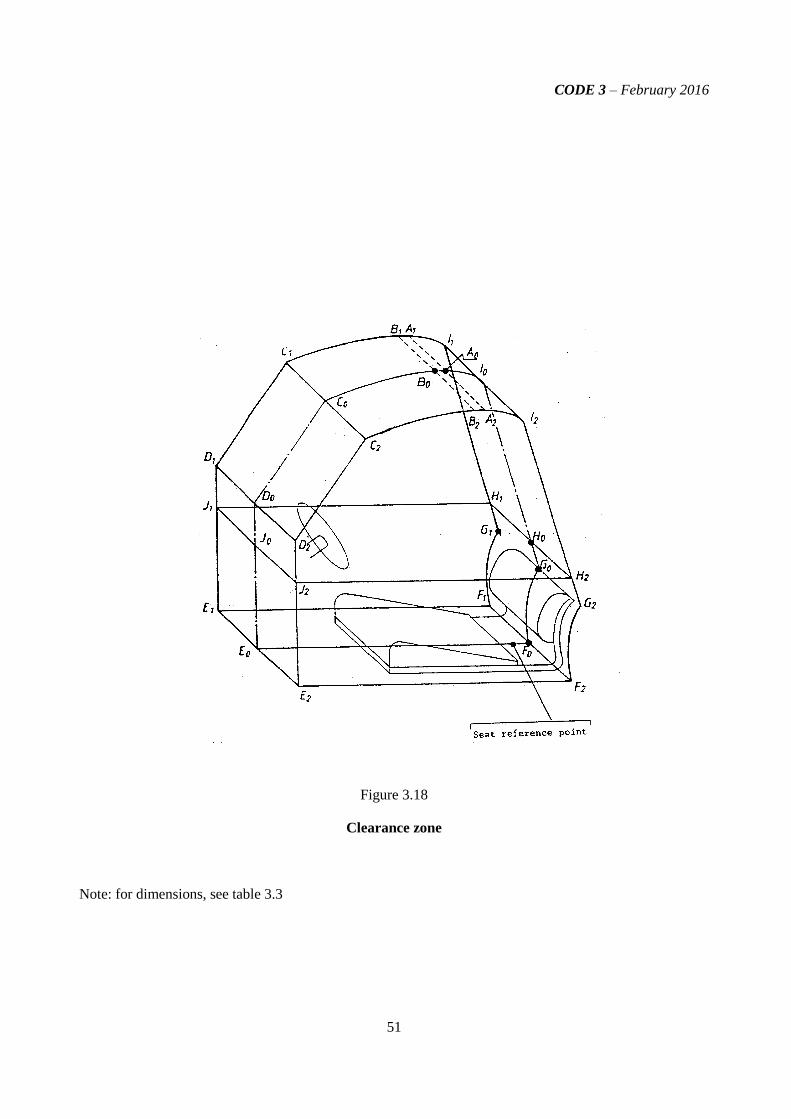
CODE 3 – February 2016
51
Figure 3.18
Clearance zone
Note: for dimensions, see table 3.3

CODE 3 – February 2016
52
Figure 3.19
Clearance zone - side view
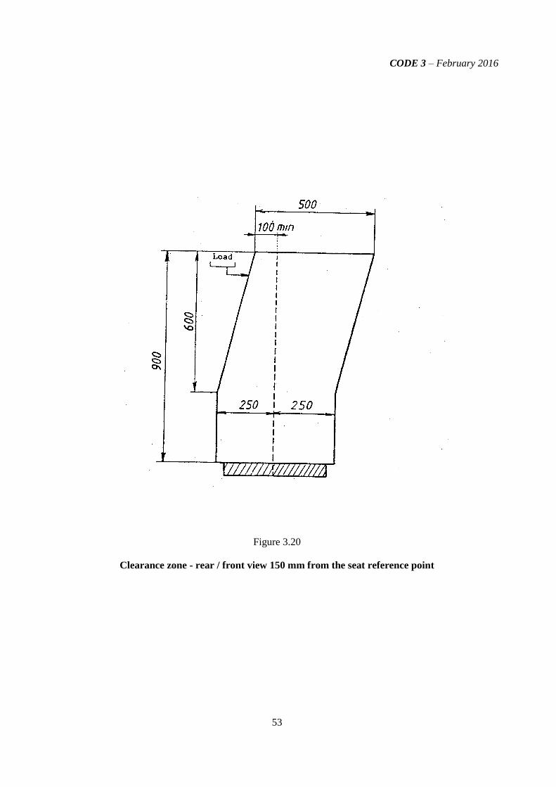
CODE 3 – February 2016
53
Figure 3.20
Clearance zone - rear / front view 150 mm from the seat reference point
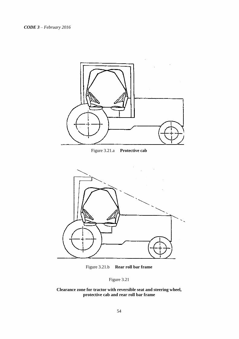
CODE 3 – February 2016
54
Figure 3.21.a Protective cab
Figure 3.21.b Rear roll bar frame
Figure 3.21
Clearance zone for tractor with reversible seat and steering wheel,
protective cab and rear roll bar frame


![digital.sa.gov.au€¦ · Web viewInformation Security Management Framework . ... Code-word information. ... Australian Government Protective Security Policy Framework [PSPF]](https://static.fdocuments.net/doc/165x107/5acd92667f8b9a6a678da9cb/web-viewinformation-security-management-framework-code-word-information.jpg)