DIG Application Manual for Filter Hybridization - Roche Applied
Upload
nguyenminhCategory
view
261download
0
cobas h 232Operator’s Manual

Manual version Revision date Changes
Version 1.0 2016-10 New document with country-specific information on Cleaning and Disinfection (based on International Operator’s Manual 0 7469101001 (02) 2016-06 EN).
Version 1.1 2017-11 Update: Added Super Sani-Cloth Germicidal Disposable Wipes as recommended disinfect-ing agent; minor editorial revisions.

0 7886594001 (02) 2017-11 EN-CAN
cobas h 232
Operator’s Manual
Version 1.1

© 2006-2017, Roche Diagnostics GmbH. All rights reserved
The contents of this document, including all graphics, are the property of Roche Diagnostics. Information in this document is subject to change without notice. Roche Diagnostics shall not be liable for technical or editorial errors or omissions contained herein. No part of this document may be reproduced or transmitted in any form or by any means, electronic or mechanical, for any purpose, without the express written permission of Roche Diagnostics.
Please send questions or comments about this manual to your local Roche representative.
ROCHE CARDIAC, COBAS, COBAS H and IQC are trademarks of Roche.
The Wi-Fi CERTIFIED Logo is a certification mark of the Wi-Fi Alliance.

5
On the packaging and on the identification plate of the meter you may encounter the following symbols, shown here with their meaning:
On meters with WLAN capability:
For other WLAN certifications, see label on bottom of battery compartment and addendum for information on WLAN registration.
The user is fully responsible for the installation, use and upkeep of the cobas h 232 meter.
Caution, consult accompanying documents. Refer to safety-related notes in the instructions for use accompanying this instrument.
Temperature limitation (Store at)
Manufacturer
Catalogue number
In vitro diagnostic medical device
Global Trade Item Number
This product fulfills the requirements of the European Directives 98/79/EC on in vitro diagnostic medical devices and 1999/5/EC on radio and telecommunications terminal equipment (R&TTE).
The system fulfills the Canadian and U.S. safety requirements (UL LISTED, in accordance with UL 61010A-1:02 and CAN/CSA-C22.2 No.61010-1-04).
This device complies with Part 15 of the FCC Rules and with RSS-210 of Industry Canada
IVD

This page intentionally left blank.

Table of Contents
7
1 Introduction 11The cobas h 232 meter................................................................................................................. 11Test principle ..................................................................................................................................... 13Contents of the Pack ...................................................................................................................... 13
1.1 Important safety instructions and additional information......................................................... 14Safety information ........................................................................................................................... 15Disposal of the system .................................................................................................................. 17Battery pack ....................................................................................................................................... 17General care....................................................................................................................................... 19Electrical safety ................................................................................................................................ 19Electromagnetic interference ...................................................................................................... 20Touchscreen....................................................................................................................................... 20Local Area Network: protection from unauthorized access ............................................ 20Wireless connectivity ...................................................................................................................... 22Radiofrequency radiation exposure information.................................................................. 22
1.2 Overview of the meter and its accessories..................................................................................... 24Meter ................................................................................................................................................... 24Power supply...................................................................................................................................... 27Test strip .............................................................................................................................................. 29Handheld Base Unit ........................................................................................................................ 30
1.3 Overview of the Buttons and Icons used on Screen................................................................... 312 Putting the Meter into Operation 35
2.1 Installing or replacing the battery pack........................................................................................... 36Removing the battery pack .......................................................................................................... 37Installing the battery pack ............................................................................................................ 38Powering the meter on and off ................................................................................................... 41
3 Meter Setup 43Settings summary............................................................................................................................. 44
3.1 Basics setup ............................................................................................................................................... 49Contrast ............................................................................................................................................... 49Language ............................................................................................................................................ 51Setting the date................................................................................................................................. 53Setting the time................................................................................................................................. 55Setting the display options for date and time ....................................................................... 57Sound.................................................................................................................................................... 59Auto off ................................................................................................................................................ 62
3.2 Data Handling setup ............................................................................................................................... 64Connection ........................................................................................................................................ 64QR Code .............................................................................................................................................. 65Computer............................................................................................................................................. 68Printer ................................................................................................................................................... 69Result memory .................................................................................................................................. 71Result units......................................................................................................................................... 75Result display mode........................................................................................................................ 78Diagnostics......................................................................................................................................... 80
3.3 ID Setup setting ........................................................................................................................................ 82Administrator ID ............................................................................................................................... 83Operator ID......................................................................................................................................... 89Patient ID............................................................................................................................................. 93

Table of Contents
8
3.4 Lockout setup ............................................................................................................................................ 96Operator lockout............................................................................................................................... 97Quality control (QC) settings .................................................................................................... 100Quality control (QC) lockout ..................................................................................................... 102Instrument quality control (IQC) lockout.............................................................................. 104QC result format ............................................................................................................................ 105Custom Range Troponin T ......................................................................................................... 106Reset test parameters.................................................................................................................. 108Cleaning lockout............................................................................................................................ 109STAT test configuration .............................................................................................................. 110
3.5 Optional Screens setup ....................................................................................................................... 1124 Performing a Test 115
Sample material ............................................................................................................................ 1174.1 Preparing to test .................................................................................................................................... 117
Code chip ......................................................................................................................................... 118Inserting the code chip .............................................................................................................. 119Test steps (overview) ................................................................................................................... 120Powering on the meter................................................................................................................ 122Logging in ........................................................................................................................................ 123
4.2 Performing a test ................................................................................................................................... 126Inserting a test strip .................................................................................................................... 130Displaying, confirming or adding comments to results.................................................. 136Displaying the test result as QR code ................................................................................... 139STAT tests ........................................................................................................................................ 140
5 Control Testing and Quality Control 1415.1 Preparing to run a quality control test .......................................................................................... 1435.2 Performing a quality control test ..................................................................................................... 144
Quality control (QC) ..................................................................................................................... 144Instrument quality control (IQC).............................................................................................. 152
6 Review Results 155Reviewing test results.................................................................................................................. 155Patient history ................................................................................................................................. 157All results.......................................................................................................................................... 158Quality control (QC) results....................................................................................................... 159Instrument quality control (IQC) results ............................................................................... 160Maintenance history .................................................................................................................... 161
7 Extended Functionalities 163Data handling ................................................................................................................................. 163Computer (Setup option)............................................................................................................ 164Software updates ......................................................................................................................... 164Operator lists................................................................................................................................... 165Patient lists....................................................................................................................................... 166Barcode scanner............................................................................................................................ 167Stored test results and comments .......................................................................................... 167
Table of Contents
9
8 Maintenance and Care 1698.1 Conditions for storage and shipping ............................................................................................. 169
Storage.............................................................................................................................................. 169Shipping............................................................................................................................................ 170
8.2 Cleaning and disinfecting the meter ............................................................................................. 171Difference between cleaning and disinfecting.................................................................. 171When should the meter be cleaned and disinfected? .................................................... 171What to clean and disinfect? .................................................................................................... 171Recommended cleaning/disinfecting agents..................................................................... 173Cleaning after contamination due to mispipetting........................................................... 174Cleaning the meter ....................................................................................................................... 175Disinfecting the meter................................................................................................................. 177
9 Troubleshooting 179Errors and unusual behavior without error messages .................................................... 180Meter reset ...................................................................................................................................... 182
10 General Product Specifications 18310.1 Operating conditions and technical data..................................................................................... 183
Technical data ................................................................................................................................ 183Sample material ............................................................................................................................. 184Storage and transport conditions ........................................................................................... 184
10.2 Further information............................................................................................................................... 185Ordering information ................................................................................................................... 185Product limitations........................................................................................................................ 187Information about software licenses .................................................................................... 187Repairs .............................................................................................................................................. 187
11 Warranty 187A Appendix 189
A.1 Working with barcodes....................................................................................................................... 189A.2 Operator and patient ID barcode masks...................................................................................... 190A.3 Example of barcode symbologies ................................................................................................... 191A.4 Supported characters in 2D barcodes .......................................................................................... 193
B Appendix 195B.1 Option: Wireless network (WLAN) ................................................................................................. 195
Preliminary note............................................................................................................................. 195Background..................................................................................................................................... 195Technical implementation.......................................................................................................... 196RF specific functionalities and effective performance claims...................................... 198
C Supplement for Observed Test Sequence 201Observed Test Sequence (OTS) ............................................................................................. 201Using the OTS function............................................................................................................... 202
D Contact Roche 205Index 207

Table of Contents
10
This page intentionally left blank.
Introduction
11
1 Introduction
The cobas h 232 meter
The cobas h 232 meter is an instrument for the quantitative evaluation of immunoassays using the gold-labeling technique. The rapid diagnostic tests in strip format available for this meter support efficient diagnosis and assessment of cardiovascular diseases. The evaluation of these tests with the cobas h 232 meter combines the advantages of a rapid diagnosis with enhanced clinical interpretation of quantitative values (in comparison with qualitative tests). In addition, automated evaluation provides more reliable results by eliminating the potential sources of error associ-ated with visual reading. Refer to the package inserts accompanying the test strips for detailed information on specific tests.
Readings may be carried out directly where the blood samples are taken. Therefore, the cobas h 232 meter is ideal for use at the point of care in emergency rooms, intensive care units and ambulances, as well as by cardiologists and general practitioners. The cobas h 232 meter is rapid and easy to operate: Insert an unused strip in the meter and apply the sample. After the reaction period, the meter provides a quantitative result; in addition, a qualitative result is pro-vided prior to the end of some tests.
The cobas h 232 meter has the ability to connect to a data management system (DMS) by means of wireless communication (if the meter is equipped with WLAN functionality) or through the Handheld Base Unit from Roche Diagnostics (available separately). The cobas h 232 meter supports data exchange via the POCT1A standard. Data management systems may have the ability to expand the security features of the meter, such as enabling operator lockouts. Data management systems may also enable data transfer to an LIS or HIS. Refer to the manuals of the Handheld Base Unit and of your DMS for technical details.

Introduction
12
Read this operator's manual, as well as the package inserts for all relevant consumables, before using the system for the first time. You must configure the cobas h 232 meter according to your needs before initial use. Refer to Chapter 3, “Meter Setup”. Be sure to read the “Important safety instructions and additional information” section in this chapter before operating the system.
For all questions about the cobas h 232 system that are not answered in this manual, contact your Roche representative (see “Contact Roche” on page 205). In order to expedite troubleshoot-ing, please have ready your cobas h 232 meter, its serial number, this manual, and all related consumables when you call.
If you connect your cobas h 232 meter to a cobas IT 1000 data management system or another PC/DMS, you will not be able to print directly from the meter to a printer. In order to print out meter data, use printers connected to the respective PC/DMS.

Introduction
13
Test principle
Two lines (signal and control line) in the detection zone of the test strip indicate whether the analyte to be determined is present in the sample material. These lines are detected by the cobas h 232 meter with the help of an LED (lighting the detection zone) and a camera sensor (imaging the detection zone). The test signal (signal line) increases in intensity in proportion to the concentration of the respective analyte. Integrated system software converts the signal intensity to a quantitative result, which is then displayed on the screen at the end of the measurement.
The accuracy of the measurement is ensured through a simple principle: Every test strip box includes a code chip that contains all test and lot-specific information in electronic format. The test strips are labelled with a barcode on their underside and are hereby assigned to a specific code chip. When you insert a test strip from a new strip lot for the first time, the meter prompts you to plug in the corresponding code chip. The information is now read from the code chip and stored for future tests.
Contents of the Pack
■ cobas h 232 meter
■ Power adapter
■ Universal Battery Pack
■ Battery compartment cover
■ Torx screw driver for mounting the battery compartment cover
■ Operator’s Manual in English
■ Quick Reference Guide
■ CD-ROM with operator’s manual in other languages
Optionally available (not included in the scope of delivery):
■ Handheld Base Unit (docking station) for data transfer within a network or via USB (Universal Serial Bus)
For a personal printout of the operator’s manual in your language, contact your local Roche organization (see Chapter A).
Introduction
14
1.1 Important safety instructions and additional information
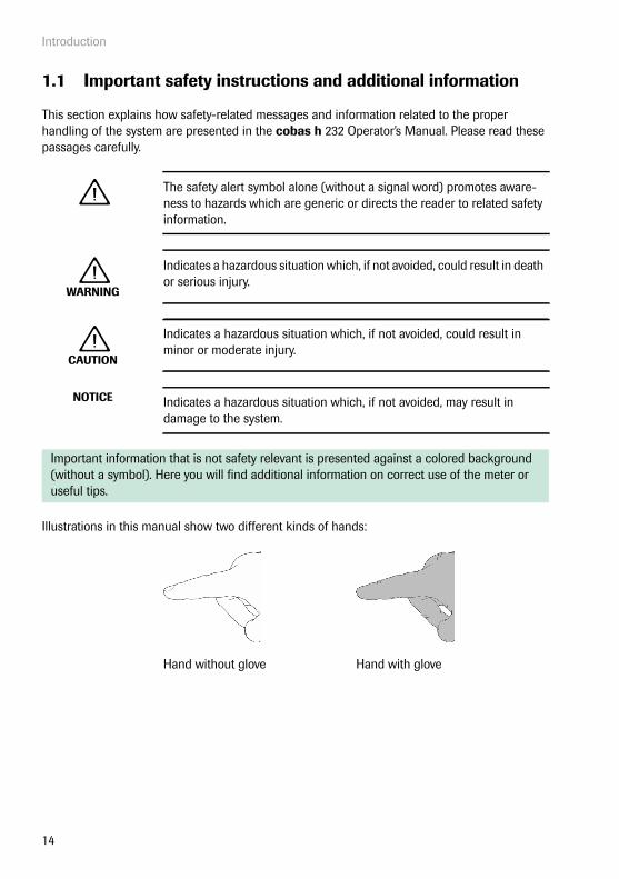
This section explains how safety-related messages and information related to the proper handling of the system are presented in the cobas h 232 Operator’s Manual. Please read these passages carefully.
The safety alert symbol alone (without a signal word) promotes aware-ness to hazards which are generic or directs the reader to related safety information.
WARNING
Indicates a hazardous situation which, if not avoided, could result in death or serious injury.
CAUTION
Indicates a hazardous situation which, if not avoided, could result in minor or moderate injury.
NOTICE Indicates a hazardous situation which, if not avoided, may result in damage to the system.
Important information that is not safety relevant is presented against a colored background (without a symbol). Here you will find additional information on correct use of the meter or useful tips.
Illustrations in this manual show two different kinds of hands:
Hand without glove Hand with glove

Introduction
15
Safety information
Operator qualification
Only trained healthcare professionals may operate the cobas h 232 meter. Operators must also have received comprehensive instruction in the operation, quality control, and care of the cobas h 232 meter.
WARNING
QC and IQC Lockouts
QC and IQC lockouts are disabled by default. For routine confirmation of system reliability it is strongly recommended to enable this feature. See QC recommendations on page 142.
WARNING
Protection against infection and blood-borne pathogens
Healthcare professionals using the cobas h 232 meter to perform tests must be aware that any object coming into contact with human blood is a potential source of infection. Operators need to adhere to Standard Precautions when handling or using the cobas h 232 meter. All parts of this system should be considered potentially infectious and are capable of transmitting blood-borne pathogens between patients and between patients and healthcare professionals.
■ Use gloves. Wear a new pair of clean gloves for testing each patient.
■ Wash hands thoroughly with soap and water before putting on a new pair of gloves and performing the next patient test.
■ Dispose of used syringes, tubes, pipettes, test strips, and all other materials coming into contact with blood according to your institu-tion’s infection control policy.
■ Follow all health and safety regulations in force locally.

Introduction
16
CAUTION
Allergy or injury caused by reagents and other working solutions
Direct contact with reagents, detergents, cleaning/disinfection solutions, or other working solutions may cause skin irritation or inflammation.
■ Always use protective gloves.
■ Observe the cautions given in the package inserts of the reagents and cleaning/disinfection solutions.
■ If a reagent, control, or cleaning/disinfection solution comes into con-tact with your skin, wash it off immediately with water.
■ Follow all health and safety regulations in force locally.
WARNING
Avoidance of electrical shock, fire, and explosions
■ Only use Roche Diagnostics original accessories (cables, power supply units, battery packs, and spare parts). Third-party cables, power supply units, and battery packs can cause the battery pack to explode or the meter to become damaged.
■ Do not use loose power sockets or damaged power supply units, cables, plugs, or battery packs.
■ Do not short circuit the power supply unit, the handheld base unit contacts, or the battery pack.
■ Do not drop the cobas h 232 meter, the power supply unit, or the battery pack and protect these against shaking and vibrations.

Introduction
17
Disposal of the system
Battery pack
The meter contains a rechargeable battery pack that begins charging as soon as the power adapter is connected or the meter is placed on an active Handheld Base Unit (i.e., one connected to a power adapter).
WARNING
Infection by a potentially biohazardous instrument
The cobas h 232 meter or its components must be treated as potentially biohazardous waste. Decontamination (i.e., a combination of processes including cleaning, disinfection and/or sterilization) is required before reuse, recycling, or disposal.
Dispose of the system or its components according to the appropriate local regulations. Always remove the battery pack before thermal disinfection.
NOTICE Use only the specially designed battery pack provided by Roche Diagnostics. Using any other type of battery may damage the system.
Introduction
18
WARNING
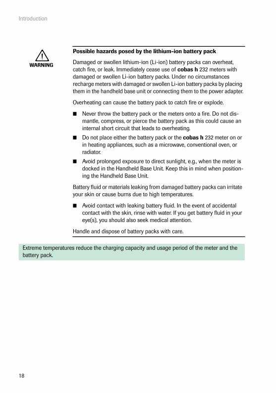
Possible hazards posed by the lithium-ion battery pack
Damaged or swollen lithium-ion (Li-ion) battery packs can overheat, catch fire, or leak. Immediately cease use of cobas h 232 meters with damaged or swollen Li-ion battery packs. Under no circumstances recharge meters with damaged or swollen Li-ion battery packs by placing them in the handheld base unit or connecting them to the power adapter.
Overheating can cause the battery pack to catch fire or explode.
■ Never throw the battery pack or the meters onto a fire. Do not dis-mantle, compress, or pierce the battery pack as this could cause an internal short circuit that leads to overheating.
■ Do not place either the battery pack or the cobas h 232 meter on or in heating appliances, such as a microwave, conventional oven, or radiator.
■ Avoid prolonged exposure to direct sunlight, e.g., when the meter is docked in the Handheld Base Unit. Keep this in mind when position-ing the Handheld Base Unit.
Battery fluid or materials leaking from damaged battery packs can irritate your skin or cause burns due to high temperatures.
■ Avoid contact with leaking battery fluid. In the event of accidental contact with the skin, rinse with water. If you get battery fluid in your eye(s), you should also seek medical attention.
Handle and dispose of battery packs with care.
Extreme temperatures reduce the charging capacity and usage period of the meter and the battery pack.
Introduction
19
Observe the following general safety instructions for handling the battery pack:
■ When storing or disposing of the battery pack, use the manufacturer's original packaging.
■ Always power the meter off before removing the battery pack.
■ When the Battery Low warning is displayed, the meter must be returned as soon as pos-sible to the Handheld Base Unit or connected to the power adapter for recharging.
■ When the battery capacity is too low for further tests, the meter must be returned imme-diately to the Handheld Base Unit or connected to the power adapter for recharging.
General care
Electrical safety
Disposal of used battery packs
Do not dispose of the battery pack with normal domestic waste. Dispose of used battery packs in accordance with applicable local regulations and directives and your facility’s guidelines on the disposal of electronic waste equipment.
Save or download data from the meter prior to replacing the battery pack to prevent loss of data (see Chapter 7).
NOTICE Clean the meter only with the solutions recommended (see page 173). Using other solutions may result in incorrect operation and possible fail-ure of the system. Make sure that the meter is thoroughly dried after cleaning and disinfecting.
NOTICE Never run the meter if the electrical power adapter or the attached cable is visibly damaged. If there is any visible damage contact your local Roche service for inspections.
Introduction
20
Electromagnetic interference
The meter fulfills the IEC 61326-2-6 requirements for emitted interference and interference immunity.
Touchscreen
Local Area Network: protection from unauthorized access
■ If this product is connected to a local area network, this network must be protected against unauthorized access. In particular, it must not be linked directly to any other net-work or the Internet. Customers are responsible for the security of their local area net-work, especially in protecting it against malicious software and attacks. This protection might include measures, such as a firewall, to separate the device from uncontrolled net-works as well as measures that ensure that the connected network is free of malicious code.
■ If you use a customized data management system solution, ensure that sensitive data transmitted via the POCT1-A interface is protected by appropriate security measures.
■ Ensure that the instrument is protected against unauthorized physical access and theft.
■ Do not use shared user or operator accounts on meter, DMS and network.
■ Whether working in a wired or wireless environment, use a strong password for user or operator accounts on the meter, DMS, and network. Observe your own facility guidelines on password management where available, or apply the rules for strong passwords, see “Characteristics of strong passwords” below.
Do not use the meter near strong electromagnetic fields, which could interfere with the proper operation of the meter.
Electrostatic discharges may cause malfunction of the meter.
NOTICE ■ Use only your finger (even when wearing gloves) or special pens designed for use with handheld devices to touch the screen elements. Using pointed or sharp-edged objects can damage the touchscreen.
■ Do not use the system in direct sunlight. Direct sunlight may reduce the life expectancy and functionality of the screen.

Introduction
21
Characteristics of strong passwords
■ Passwords must not contain the user’s account name or parts of the user’s full name that exceed two consecutive characters.
■ Passwords must be at least eight characters in length.
■ Passwords must contain characters from at least three of the following four categories:
– English uppercase alphabetic characters (A through Z)– English lowercase alphabetic characters (a through z)– Numeric characters (0 through 9)– Non-alphabetic characters (for example, !, $, #, %)
Examples of weak passwords
■ uhxwze11 contains no upper case letter.
■ UHXW13SF contains no lower case letter.
■ uxxxxx7F contains the same character more than four times.
■ x12useridF contains a substring of the user ID longer than four characters.
To ensure that your cobas h 232 meter functions properly, observe the operating and storage conditions as given in the chapter “General Product Specifications”, starting on page 183.

Introduction
22
Wireless connectivity
If the meter is equipped with WLAN functionality:Wireless connectivity allows the meter to send data (test results, patient IDs, operator IDs, etc.) to the data management system without the need to return the meter to the Handheld Base Unit. This feature must be configured by the system administrator. Observe the guidelines of your facility for using wireless local area network connections. For a description of the cobas h 232 meter’s ability to connect to Wireless Local Area Networks (WLAN, Wi-Fi), see appendix B.
Radiofrequency radiation exposure information
The Industrial, Scientific and Medical (ISM) radio frequencies may contain emissions from micro-wave ovens, heaters, and other noncommunication devices. While these types of devices usually pose no threat of interference as they are low-powered devices, the possibility exists that some industrial high power systems may wipe out any attempted communication use of a WLAN. Therefore, perform a site survey and interference analysis with a spectrum analyzer to view the entire spectrum, looking for signals that might not only be within the frequency range of the intended WLAN but also could be near or at the same frequency and cause interference.
Roche Diagnostics supports industry wireless standards and recommends using products that have Wi-Fi certification. This certification tests products to the 802.11 industry standards for basic connectivity, security, authentication, Quality of
Service (QoS), interoperability and reliability. The Wi-Fi CERTIFIED logo is an assurance that the Wi-Fi Alliance has tested a product in numerous configurations and with a diverse sampling of other devices to ensure compatibility with other Wi-Fi CERTIFIED equipment that operates in the same frequency band. The Wi-Fi Alliance network of independent test labs conducts inter-operability testing programs to ensure that wireless devices work together and support secure connections.
Glossary:
■ “FCC” stands for “Federal Communications Commission” (USA).
■ “RF” stands for “radio frequency”
■ “RSS” stands for “Radio Standards Specification” (Canada).
■ “WLAN” stands for “Wireless Local Area Network”

Introduction
23
The cobas h 232 system complies with FCC radiation exposure limits set forth for an uncon-trolled environment. This equipment should be installed and operated with minimum distance of 20 cm (8 inches) between the radiator and your body.
This transmitter must not be co-located or operated in conjunction with any other antenna or transmitter.
Changes or modifications made to this equipment not expressly approved by Roche Diagnostics may void the FCC authorization to operate this equipment.
This device complies with Part 15 of the FCC Rules and with RSS-210 of Industry Canada. Operation is subject to the following two conditions:
(1) this device may not cause harmful interference,
and
(2) this device must accept any interference received, including interference that may cause undesired operation.
The cobas h 232 system complies with the emission and immunity requirements described in EN 61326-2-6. It has been designed and tested to CISPR 11 Class B.
This equipment has been tested and found to comply with the limits for a Class B digital device, pursuant to Part 15 of the FCC Rules. These limits are designed to provide reasonable protection against harmful interference in a residential installation. This equipment generates, uses and can radiate radio frequency energy and, if not installed and used in accordance with the instructions, may cause harmful interference to radio communications. However, there is no guarantee that interference will not occur in a particular installation. If this equipment does cause harmful inter-ference to radio or television reception, which can be determined by powering the equipment off and on, the user is encouraged to try to correct the interference by one or more of the following measures:
■ Reorient or relocate the receiving antenna.
■ Increase the separation between the equipment and receiver.
■ Connect the equipment into an outlet on a circuit different from that to which the receiver is connected.
■ Consult the dealer or an experienced radio/TV technician for help.
This Class B digital apparatus complies with Canadian ICES-003.
Introduction
24
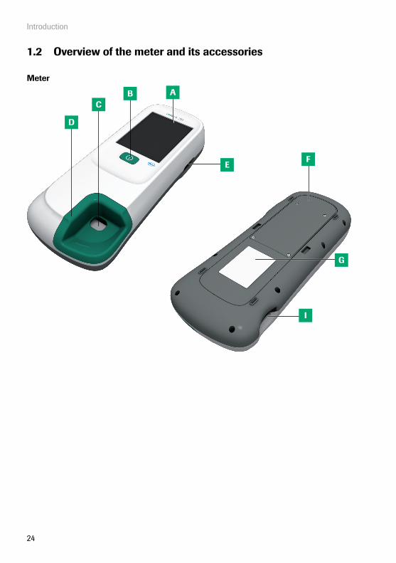
1.2 Overview of the meter and its accessories
Meter
AB
D
C
I
E
G
F

Introduction
25
* To determine if your meter has this function compare the REF number on the meter identifica-tion plate to the corresponding ordering information (list of REF numbers) on page 186.
A TouchscreenShows results, information, icons and results saved in the memory. To select an option, simply touch the button lightly.
B On/Off buttonPress this button to power the meter on or off.
C Opening for sample applicationOpening in the test strip guide cover that enables you to apply blood once the test strip is inserted.
D Test strip guide coverRemove this cover to clean the area underneath (if it has become soiled, e.g., with blood).
E Barcode scannerOperator and patient IDs can be read into the meter using the integrated barcode scanner. *
F Battery compartment coverRemove to insert the battery pack.
G Meter identification plateSee page 5 for symbol explanation.
H Wireless LAN labelIf the meter supports wireless connectivity: This label displays registration numbers that are specific to the meter RF hard-ware. *
H N

Introduction
26
I Test strip guideInsert the test strip here.
J Infrared (IR) window Supports data communication with the (optional) Handheld Base Unit. Covered by the semi-transparent rear panel.
K Connection socket for power adapterPlug in the power adapter here.
L Code chip slotInsert the code chip here.
M Charging terminalsUsed for power supply and/or charging the battery pack when the meter is docked in the (optional) Handheld Base Unit.
I
J
K L M

Introduction
27
Power supply
The meter can be operated with the rechargeable battery pack only or together with the power adapter or the (optional) Handheld Base Unit, which both charge the battery pack when inserted. Insert the battery pack even when always using the power adapter or the Handheld Base Unit. This ensures that you will not lose the date and time settings if the power goes out. Results are retained in the memory together with the corresponding date and time, as well as all other set-tings, even when no battery pack is inserted.
In general, it is not recommended to detach the external power supply or undock the meter from the Handheld Base Unit during a measurement. When the meter is connected to an external power supply and the battery level is low, measurements cannot be completed if the external power supply is detached. In this case a message is displayed not to remove the external power supply.
To save power, the meter can automatically power itself off or go into standby mode, if no buttons are pressed or new test strips are inserted. When the meter powers itself off, all test results obtained up to that point remain in memory and the settings are retained (see “Auto off” in the chapter entitled “Data Handling setup” on page 62).
N Universal Battery PackPowers the device.
O Power adapterPowers the device and charges the battery pack.
N O

Introduction
28
During battery operation, the meter always displays the power level of the battery pack. The battery icon is divided into four segments which correspond to the battery power level.
When replacing the battery pack, insert the new battery pack within 24 hours of removing the old one. Otherwise you may need to re-enter date and time.
Dispose of used battery packs in an environmentally responsible manner in accordance with applicable local regulations and directives. See “Infection by a potentially biohazardous instrument” on page 17.
Main Menu
Control Test
Review Results
Setup
Patient Test
09:15 am
Logout
04/19/2016

Introduction
29
Test strip
P Test areaThis area is evaluated by the meter via the camera.
Q Sample application areaThe sample is applied to this area after inserting the test strip in the meter.
R BarcodeAssigns the strip to the corresponding code chip. The barcode is automatically read by the meter when the strip is inserted into the test strip guide.
S Code chipContains strip lot specific data.
P
Q
S
R

Introduction
30
Handheld Base Unit
T Charging contactsUsed for power supply and/or charging the battery pack.
U Status indicator Lights up when power is connected, charge indicator.
V Infrared (IR) windowFor communication with the meter.
W Extension piece For cobas h 232 meter, optional.
X Data ports (Ethernet/RJ45 and USB)For connecting the device to a Data Management System (DMS).
Y Connection socket for thepower adapterHere you can plug in the power adapter of the Handheld Base Unit.
Z Removable cover for configuration switchThe switch sets the mode of operation for the Handheld Base Unit.
The Handheld Base Unit can be ordered separately. For detailed information on usage and configuration please consult the operator's manual of the Handheld Base Unit and the Technical Note stored on the Handheld Base Unit itself.
T
U
V
Y
Z
W
X

Introduction
31
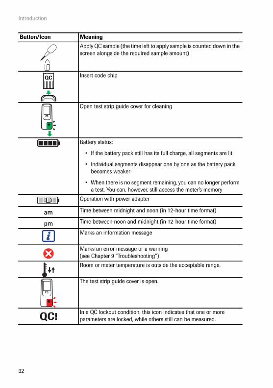
1.3 Overview of the Buttons and Icons used on Screen
The buttons and icons that appear during normal operation are shown here, along with a general explanation. Error messages and the description of the icons linked to them are provided in a separate chapter. See “Troubleshooting” starting on page 179.
Button/Icon Meaning
OK, save setting
Cancel, discard setting
Return (to previous menu)
Decrease/increase a numeric value orScroll through lists that are too long to be displayed at once
Inactive button; value cannot be further decreased/increased orEnd of list in this direction is reached
Return to the Main Menu screen
List of tests of an individual patient
Scroll through stored results
Print displayed result (via infrared interface to corresponding printer)
Display test result as QR code
Add a comment
Operator logout
Operator login
Operator must wait until the meter has completed an action.
Insert test strip
Remove test strip
Test strip warming up
Apply sample (the time left to apply sample is counted down in the screen alongside the required sample amount)
Introduction
32
Apply QC sample (the time left to apply sample is counted down in the screen alongside the required sample amount)
Insert code chip
Open test strip guide cover for cleaning
Battery status:
• If the battery pack still has its full charge, all segments are lit
• Individual segments disappear one by one as the battery pack becomes weaker
• When there is no segment remaining, you can no longer perform a test. You can, however, still access the meter’s memory
Operation with power adapter
Time between midnight and noon (in 12-hour time format)
Time between noon and midnight (in 12-hour time format)
Marks an information message
Marks an error message or a warning (see Chapter 9 “Troubleshooting”)
Room or meter temperature is outside the acceptable range.
The test strip guide cover is open.
In a QC lockout condition, this icon indicates that one or more parameters are locked, while others still can be measured.
Button/Icon Meaning
QC
am
pm
QC!

Introduction
33
The following icons may appear when using the meter in conjunction with a data management system (DMS).
Infrared interface is enabled (for communication with the computer and/or printer)
Communication is taking place via WLAN
An OTS request is pending
Cleaning/Disinfection necessary

Introduction
34
This page intentionally left blank.

Putting the Meter into Operation
35
2 Putting the Meter into Operation
Before using the meter for the first time, perform the following steps:
1 Install the battery pack (see page 38)
2 Connect the power adapter to charge the battery pack
3 Set the current date and time as well as the appropriate display format (see Chapter “Meter Setup” starting on page 43)
4 Enter the settings of choice (language, quality controls – where necessary, user administration, etc.)
If the meter has no date/time settings (either because you are powering on the meter for the first time or because the battery pack was removed from the meter for more than 24 hours), you cannot perform a test. In that case powering on the meter takes you immediately to the Setup mode, where you must set the date and time.
Putting the Meter into Operation
36
2.1 Installing or replacing the battery pack
When shipped, the battery pack is not installed in the meter.
Unused battery packs lose their charge over time and have to be recharged before they can be used. After installing a new battery pack, the meter should be charged overnight before testing. Please note that the battery pack will only reach full capacity once it has been fully emptied and charged several times.
Whenever the meter is placed on an active Handheld Base Unit or powered by the power adapter, the icon is displayed. This icon shows that power is available and the meter can be charged if necessary.
Make sure that the permitted temperature range for charging the battery pack (12-32 °C or 54-90 °F) is maintained during installation and initial setup.

Putting the Meter into Operation
37
Removing the battery pack
1 If a battery pack is already installed, make sure that the meter is powered off.
Always disconnect the external power supply before removing the battery pack.
2 Place the meter face down on a level sur-face.
3 Use the starshaped Torx screw driver (delivered with the cobas h 232 product pack/kit) to remove the four screws hold-ing the battery compartment cover in place.
4 Remove the battery compartment cover from the meter. The battery pack now vis-ible is connected to the meter by a plug.
5 Carefully lift the battery pack and remove the plug connector.
Disposal of used battery packs
Do not dispose of the battery pack with normal domestic waste. Dispose of used battery packs in accordance with applicable local regulations and directives and your facility’s guidelines on the disposal of electronic waste equipment.

Putting the Meter into Operation
38
Installing the battery pack
1 Loosen the screws on the battery com-partment cover until they are protruding about 4-5 mm (2/10 in).
Always disconnect the external power supply before inserting the battery connector plug.
2 Hold the battery pack in your hand, with the wires and the plug pinched between your thumb and index finger.
3 Plug the connector plug into the socket and make sure it is fully inserted.
4 Place the battery pack inside the battery compartment as shown.
To position the battery pack correctly, always align the ridges on the side of the battery pack with the ridges on the inside of the battery compartment.
Preferably use the battery pack that was shipped with the meter. When the battery pack is installed, the meter checks if battery pack and meter are compatible.

Putting the Meter into Operation
39
5 Place the cover on the battery compart-ment. Make sure that the plug connector wires do not get pinched between meter and cover.
6 Tighten all four screws until snug (do not overtighten).

Putting the Meter into Operation
40
After inserting a new battery pack, the meter should be charged overnight before testing.
The meter powers on automatically and the Roche logo is displayed. If the meter does not start up automatically, the battery pack may be empty. In this case either a red battery symbol or a charging symbol is displayed. When the battery pack is charged sufficiently, the meter starts up automatically.
7 If the meter has been without power for too long, you have to re-enter the date and time settings. After you have entered the correct information, confirm each screen with .
Set Date
Month: 1
Day: 1
Year: 2016
04/19/2016Minutes: 49
Hour: 3Set Time
04/19/2016
AM PM

Putting the Meter into Operation
41
Powering the meter on and off
1 Power the meter on by pressing the button.
You can also power on the meter directly by connecting the power adapter or by placing the meter on the Handheld Base Unit.
2 To power the meter off after use, press the button for approximately 1 second.

Putting the Meter into Operation
42
This page intentionally left blank.

Meter Setup
43
3 Meter Setup
Buttons are screen prompts that cause something to happen when touched. In this manual the names of all buttons are either shown as bold text or as the icon used on the button (e.g., for OK ).
When text refers to other screen elements (e.g., Menu titles), these are written in italics. These screen elements are not active.
You can open any displayed function by touching (or tapping) the button for it with your finger (or a special pen for this purpose). “Tap” means: Touch the button, then remove your finger from the touchscreen. The next screen appears once you remove your finger.
1 Touch Setup to call up the Setup menu.
2 Select the group of settings of choice (see the Settings summary following this section).
For a description of the buttons and icons used on screen see page 31.
Data Handling
ID Setup
Lockout
Basics
Optional Screens
Setup
04/19/2016
Main Menu
Control Test
Review Results
Setup
Patient Test
09:15 am
04/19/2016

Meter Setup
44
Settings summary
The diagram below gives an overview of the setup areas that can be accessed on the meter.
Connection Result Memory
Result Display ModeResult Units Diagnostics
Setup
Data Handling
ID Setup
Basics
LanguageContrast
Administrator ID
Operator Lockout
Start Info
Date/Time
QC Settings
Result Login
Sound
Operator ID
Cleaning Lockout
Result Confi rmation
Auto Off
Patient ID
STAT TestConfi g.
Lockout
Optional Screens

Meter Setup
45
* Default settings are labelled with an asterisk (*).
Group Subgroup Setting Values *Basics Contrast 0 – 10 (5*)
Language Dansk
Deutsch
English *
Español
Français
Italiano
Nederlands
Norsk
Português
Svenska
An installable language
Date/Time Date 01/01/2011 *
Time 12:00 am *
Date formats Day.Month.Year (31.12.2011)
Month/Day/Year (12/31/2011) *
Year-Month-Day (2011-12-31)
Time formats 24-hour time format (24H)
12-hour time format (12H), with am/pm *
Sound (Beeper) Volume Off
Low
Medium *
High
Key Click Enable
Disable *
Auto Off [minutes] Off
1 … 10 (default: 5 min *)
15, 20, 25, 30
40, 50, 60

Meter Setup
46
* Default settings are labelled with an asterisk (*).
Group Subgroup Setting Values *Data Handling Connection QR Code
Off *
Computer
Printer
Result Memory Result Display Filter All results *
Current Op. Res.
Result Storage Mode
No results deletion *
Delete oldest result
Result Units Select DD Res. Unit μg/mL *
ng/mL
mg/L
μg/L
Select TT Res. Unit ng/L *
pg/mL
ng/mL
μg/L
Result Display Mode Static *
Flashing
Diagnostics Software Display of existing settings and parameters onlyWireless Setup
ID Setup Administrator ID Blank (off) *
Operator ID (with DMS and list available on meter)
None *
List
Hidden List
(No list available on meter)
None *
Optional
Required
Scan Only
Patient ID None
Optional *
Required
Hidden List
Meter Setup
47
* Default settings are labelled with an asterisk (*).
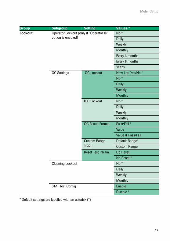
Group Subgroup Setting Values *Lockout Operator Lockout (only if “Operator ID”
option is enabled)No *
Daily
Weekly
Monthly
Every 3 months
Every 6 months
Yearly
QC Settings QC Lockout New Lot: Yes/No *
No *
Daily
Weekly
Monthly
IQC Lockout No *
Daily
Weekly
Monthly
QC Result Format Pass/Fail *
Value
Value & Pass/Fail
Custom Range Trop T
Default Range*
Custom Range
Reset Test Param. Do Reset
No Reset *
Cleaning Lockout No *
Daily
Weekly
Monthly
STAT Test Config. Enable
Disable *

Meter Setup
48
* Default settings are labelled with an asterisk (*).
Group Subgroup Setting Values *Optional screens Start Info Enable
Disable *
Result Login Enable
Disable *
Result Confirmation Enable
Disable *

Meter Setup
49
3.1 Basics setup
The Basics setup area contains the basic options for changing the user interface.
Contrast
Use the Contrast menu to adjust the display to your ambient light conditions and make it easier to read.
1 From the Main Menu, touch Setup to open the meter settings.
2 From the Setup menu, touch Basics.
3 From the Setup-Basics menu, touch Contrast.
Main Menu
Control Test
Review Results
Setup
Patient Test
09:15 am
04/19/2016
Data Handling
ID Setup
Lockout
Basics
Optional Screens
Setup
04/19/2016
Language
Date/Time
Sound
Contrast
Auto Off
Setup - Basics
04/19/2016

Meter Setup
50
4 Touch or to change the contrast in a range from 0 to 10.
■ Contrast “0” makes the screen very dark.
■ Contrast “10” makes the screen very light.
5 Touch to save this setting, or touch to exit this menu without saving any changes. The display automatically returns to the previous screen.
Select Contrast
Contrast:(0-10) 5
04/19/2016

Meter Setup
51
Language
Use this setting to select the language for all displays (that contain text).
1 From the Main Menu, touch Setup to open the meter settings.
2 From the Setup menu, touch Basics.
3 From the Setup-Basics menu, touch Language.
The current language setting is highlighted (white type on a blue background). You can select either:
■ Dansk
■ Deutsch
■ English
■ Español
■ Français
■ Italiano
■ Nederlands
■ Norsk
■ Português
■ Svenska
An optional language can be installed upon request (either directly at the plant or later by an authorised Roche Diagnostics service technician).
Main Menu
Control Test
Review Results
Setup
Patient Test
09:15 am
04/19/2016
Data Handling
ID Setup
Lockout
Basics
Optional Screens
Setup
04/19/2016
Language
Date/Time
Sound
Contrast
Auto Off
Setup - Basics
04/19/2016

Meter Setup
52
4 Touch or to display the language of choice on the screen.
If the arrow is just an outline , you have reached the end of the list in the respec-tive direction.
5 Touch the button to select the language of choice. Your selection is now highlighted.
6 Touch to save this setting, or touch to exit this menu without saving any changes. The display automatically returns to the previous screen.
Français
Italiano
Nederlands
Norsk
Português
Select Language
04/19/2016

Meter Setup
53
Setting the date
Use this menu to set the date of the meter.
1 From the Main Menu, touch Setup to open the meter settings.
2 From the Setup menu, touch Basics.
3 From the Setup-Basics menu, touch Date/Time.
Main Menu
Control Test
Review Results
Setup
Patient Test
09:15 am
04/19/2016
Data Handling
ID Setup
Lockout
Basics
Optional Screens
Setup
04/19/2016
Language
Date/Time
Sound
Contrast
Auto Off
Setup - Basics
04/19/2016
Meter Setup
54
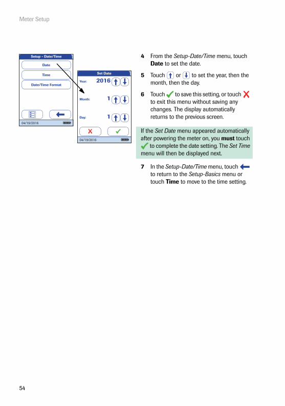
4 From the Setup-Date/Time menu, touch Date to set the date.
5 Touch or to set the year, then the month, then the day.
6 Touch to save this setting, or touch to exit this menu without saving any changes. The display automatically returns to the previous screen.
If the Set Date menu appeared automatically after powering the meter on, you must touch
to complete the date setting. The Set Time menu will then be displayed next.
7 In the Setup-Date/Time menu, touch to return to the Setup-Basics menu or touch Time to move to the time setting.
Setup - Date/Time
Time
Date/Time Format
Date
04/19/2016
Set Date
Month: 1
Day: 1
Year: 2016
04/19/2016

Meter Setup
55
Setting the time
Use this menu to set the time of the meter.
1 From the Main Menu, touch Setup to open the meter settings.
2 From the Setup menu, touch Basics.
3 From the Setup-Basics menu, touch Date/Time.
Main Menu
Control Test
Review Results
Setup
Patient Test
09:15 am
04/19/2016
Data Handling
ID Setup
Lockout
Basics
Optional Screens
Setup
04/19/2016
Language
Date/Time
Sound
Contrast
Auto Off
Setup - Basics
04/19/2016

Meter Setup
56
4 From the Date/Time menu, touch Time to set the time.
5 Touch or to set the hours, then the minutes.
6 Touch to save this setting, or touch to exit this menu without saving any changes. The display automatically returns to the previous screen.
If the Set Time menu appeared automatically after leaving the Set Date menu, you must touch to complete the time setting. The Main Menu will then be displayed next.
7 Touch to return to the Setup-Basics menu or touch Date/Time Format to move to the display options.
Setup - Date/Time
Time
Date/Time Format
Date
04/19/2016
Minutes: 49
Hour: 3Set Time
04/19/2016
AM PM

Meter Setup
57
Setting the display options for date and time
Select your preferred format for the date and time display.
1 From the Main Menu, touch Setup to open the meter settings.
2 From the Setup menu, touch Basics.
3 From the Setup-Basics menu, touch Date/Time.
Main Menu
Control Test
Review Results
Setup
Patient Test
09:15 am
04/19/2016Data Handling
ID Setup
Lockout
Basics
Optional Screens
Setup
04/19/2016Language
Date/Time
Sound
Contrast
Auto Off
Setup - Basics
04/19/2016

Meter Setup
58
4 From the Setup-Date/Time menu screen, touch Date/Time Format to set the dis-play format.
The current settings are highlighted (white type on a blue background). You can select one of the following display formats for the date:
■ Day.Month.Year, e.g., 31.12.2011
■ Month/Day/Year, e.g., 12/31/2011
■ Year-Month-Day, e.g., 2011-12-31
You can also select one of the following dis-play formats for the time:
■ 24H (24-hour time format), e.g., 14:52
■ 12H (12-hour time format, supplemented by am/pm), e.g., 2:52 pm
5 Touch the button with the display format of choice for the date and time. Your selection is now highlighted.
6 Touch to save this setting, or touch to exit this menu without saving any changes. The display automatically returns to the previous screen.
7 Touch to return to the Setup-Basics menu.
Setup - Date/Time
Time
Date/Time Format
Date
04/19/2016
Select Date Format
Date DD.MM.YYYY
MM/DD/YYYY
YYYY-MM-DD
Time 24H 12H
04/19/2016

Meter Setup
59
Sound
The cobas h 232 meter can display information visually and alert you to special circumstances with a beep sound. When the Sound is activated, the meter beeps when:
■ it is powered on
■ it detects a test strip
■ pre-heating of the test strip is complete and you need to apply a sample
■ it detects a blood sample
■ the test is completed and the results are displayed (a long beep)
■ an error occurs (three short beeps)
■ the power adapter is connected when the meter is on
■ a barcode is scanned successfully (short beep)
■ the barcode scanner is disabled (two short beeps)
■ a positive test result can be expected, while the measurement still is in progress (a long beep)
■ a test result requires operator confirmation and the meter will soon power off automati-cally (three short beeps)
You can also activate a Key Click. When the Key Click is activated, the meter clicks briefly every time a button is touched, facilitating the input of information.
We recommend that you keep the Sound (beeper) activated at all times.
Meter Setup
60
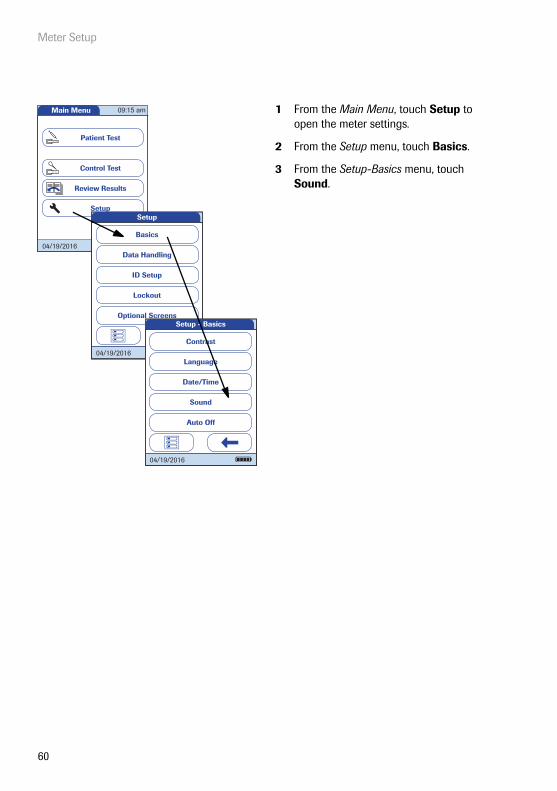
1 From the Main Menu, touch Setup to open the meter settings.
2 From the Setup menu, touch Basics.
3 From the Setup-Basics menu, touch Sound.
Main Menu
Control Test
Review Results
Setup
Patient Test
09:15 am
04/19/2016Data Handling
ID Setup
Lockout
Basics
Optional Screens
Setup
04/19/2016Language
Date/Time
Sound
Contrast
Auto Off
Setup - Basics
04/19/2016
Meter Setup
61
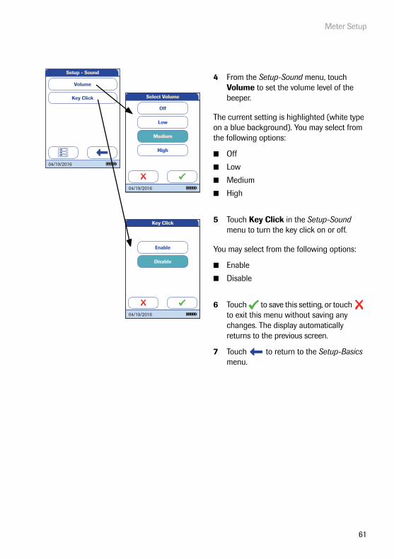
4 From the Setup-Sound menu, touch Volume to set the volume level of the beeper.
The current setting is highlighted (white type on a blue background). You may select from the following options:
■ Off
■ Low
■ Medium
■ High
5 Touch Key Click in the Setup-Sound menu to turn the key click on or off.
You may select from the following options:
■ Enable
■ Disable
6 Touch to save this setting, or touch to exit this menu without saving any changes. The display automatically returns to the previous screen.
7 Touch to return to the Setup-Basics menu.
Disable
Enable
Key Click
04/19/2016
Key Click
Volume
Setup - Sound
04/19/2016
Off
Low
Medium
High
Select Volume
04/19/2016

Meter Setup
62
Auto off
You can set up your meter so that it powers itself off automatically if it has not been used (no buttons touched or tests run) for a preselected time period. Use this feature to save power and extend the time of usage before having to recharge the battery pack.
1 From the Main Menu, touch Setup to open the meter settings.
2 From the Setup menu, touch Basics.
3 In the Setup-Basics menu, touch Auto Off.
If connected to the power adapter or the Handheld Base Unit, the meter goes into standby mode instead of powering off if it has not been used for 10 minutes. Furthermore the meter can perform a maintenance reboot on a regular basis. The latter will only occur during meter inactivity.
Main Menu
Control Test
Review Results
Setup
Patient Test
09:15 am
04/19/2016Data Handling
ID Setup
Lockout
Basics
Optional Screens
Setup
04/19/2016Language
Date/Time
Sound
Contrast
Auto Off
Setup - Basics
04/19/2016

Meter Setup
63
You may select from the following options:
■ Off (meter never powers itself off)
■ Time until meter powers itself off:1…10, 15, 20, 25, 30, 40, 50, 60 minutes
4 Touch or to select the time of choice in minutes or to deactivate the feature.
5 Touch to save this setting, or touch to exit this menu without saving any changes.The display automatically returns to the previous screen.
6 Touch to return to the Setup menu.
Set Auto Off Time
Minutes: 5
04/19/2016

Meter Setup
64
3.2 Data Handling setup
Connection
In the Connection menu you can configure the data exchange with external devices. The meter can be connected either to a computer or a printer. In addition to this direct data output, test results may also be encoded as QR codes, which can be scanned to be used with other applica-tions.
1 From the Main Menu, touch Setup to open the meter settings.
2 From the Setup menu, touch Data Handling.
3 From the Setup-Data Handling menu, touch Connection.
Main Menu
Control Test
Review Results
Setup
Patient Test
09:15 am
04/19/2016
Data Handling
ID Setup
Lockout
Basics
Optional Screens
Setup
04/19/2016
Result Memory
Result Units
Result Display Mode
Setup - Data Handling
Connection
04/19/2016
Diagnostics
Meter Setup
65
QR Code
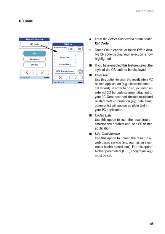
4 From the Select Connection menu, touch QR Code.
5 Touch On to enable, or touch Off to disa-ble QR code display. Your selection is now highlighted.
■ If you have enabled this feature, select the style of the QR code to be displayed:
■ Plain TextUse this option to scan the result into a PC hosted application (e.g. electronic medi-cal record). In order to do so, you need an external 2D barcode scanner attached to your PC. Once scanned, the test result and related meta-information (e.g. date, time, comments) will appear as plain text in your PC application.
■ Coded DataUse this option to scan the result into a smartphone or tablet app, or a PC hosted application.
■ URL TransmissionUse this option to upload the result to a web based service (e.g. such as an elec-tronic health record, etc.). For this option further parameters (URL, encryption key) must be set.
Select Connection
Printer
Computer
Off
QR Code
04/19/2016
QR Code
04/19/2016
Show QR code:On Off
Plain Text
Coded Data
URL Transmission

Meter Setup
66
Ensure that your environment for reading QR codes (QR code reader, operating system, text processing application) is appropriate for your language. Disregard may lead to unpredictable behavior of your receiving component (PC, mobile device).
For the options Coded Data and URL Transmission dedicated software programs or apps are required in order to use this feature. If you are a customer or a 3rd party IT provider, and you are interested to use this feature, contact your local Roche Diagnostics representative for additional information.
6 Touch Plain Text, Coded Data or URL Transmission, depending on the intended use. Your selection is now highlighted.
If you have selected URL Transmission, the button will become active. Use this button
to set the additional parameters.
7 Touch to open the URL Transmission menu.
8 Touch URL to enter the URL to which the test result data will be uploaded (note: the URL will be provided by your specialized service provider).
■ Use to switch to input of numbers.
■ Use to switch back to input of text.
■ Use to backspace and correct a mistake.
9 Touch to save this setting, or touch to exit this menu without saving any changes. The display automatically returns to the previous screen.
QR Code
04/19/2016
Show QR code:On Off
Plain Text
Coded Data
URL Transmission
URL Transmission
URL
Encryption Key
04/19/2016
URL
A B C D E
F G H I J
K L M N O
P Q R S T
U V W X Y
Z . / 123
123
ABC

Meter Setup
67
10 Touch Encryption Key to display the Encryption Key menu.
The Encryption Key menu displays two types of information which are required in order to identify and decode the transmitted test result. This information is required by the IT system, to which the test result is transmitted via the defined URL.
■ KeyThis key is auto-generated by the meter and is required to decrypt the QR code information.
■ Serial No.The meter's serial number is required to map the test result to the encryption key.
Touch the New button, if you want the meter to generate a new encryption key.
11 Touch twice to return to the QR Code menu.
12 Touch to save this setting, or touch to exit this menu without saving any changes. The display automatically returns to the previous screen.
The Encryption Key information needs to be exchanged once with your specialized service pro-vider prior to using the URL transmission method. Contact your specialized service provider in order to exchange this information.
URL Transmission
URL
Encryption Key
04/19/2016
Encryption Key
Note: The encryption key and the serial number are required to decrypt QR code messages from this meter. Ensure they are available on the target system.
Key:
Serial No.:JD5G29F6U8V2WC4L
KQ0327832
04/19/2016
Meter Setup
68
Computer
The cobas h 232 meter can connect with a computer or host system running appropriate soft-ware (that is, a DMS must be installed). To use this connectivity feature, however, you need the optional Handheld Base Unit or the meter must be configured for wireless communication. If no wireless communication is configured, the connection is established in two steps.
■ The meter connects to the Handheld Base Unit via infrared.
■ The Handheld Base Unit is either connected to a single computer (via USB) or to a net-work/host system (via Ethernet).
The option Computer (when activated) can be used together with a DMS to set up:
■ operator lists, or
■ patient lists (lists of patients to be tested)
This eliminates the need for manual entry of these data. In addition, you can transfer test results stored in the meter to other systems for archiving or further evaluation. The option Computer controls the meter’s ability to communicate with a computer or a network.
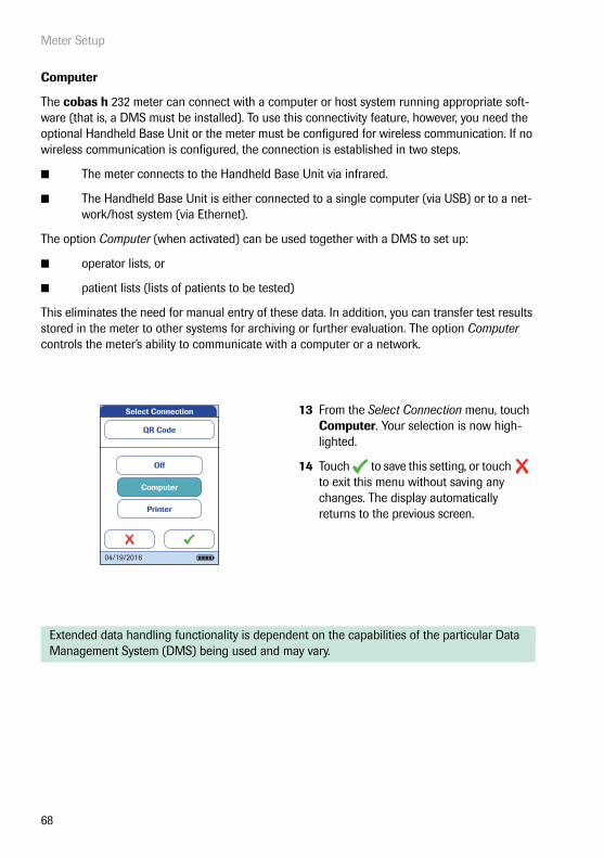
13 From the Select Connection menu, touch Computer. Your selection is now high-lighted.
14 Touch to save this setting, or touch to exit this menu without saving any changes. The display automatically returns to the previous screen.
Extended data handling functionality is dependent on the capabilities of the particular Data Management System (DMS) being used and may vary.
Select Connection
04/19/2016
Printer
Computer
Off
QR Code

Meter Setup
69
Printer
The meter can connect directly with three different infrared printers. The Handheld Base Unit cannot be used for this purpose.
The option to print is displayed in a test result as well as directly after a test and when calling up stored results. Using the settings you enter here, you can activate or deactivate the meter‘s ability to print.
Connection to a printer can only be established via infrared.
Enabling the connection to a printer disables the connection to a computer (and vice versa).
15 From the Select Connection menu, touch Printer. Your selection is now high-lighted.
16 Touch to confirm the selection. The next screen allows you to choose the type of printer you are using.
17 Touch to save this setting, or touch to exit this menu without saving any changes. The display automatically returns to the Setup-Data Handling menu.
Select Connection
Printer
Computer
Off
QR Code
04/19/2016
Citizen CMP-10
GeBE GPT-437x
Zebra MZ320
Select Printer
04/19/2016

Meter Setup
70
To print :
■ Align the meter with the IR printer
■ At any test or memory screen, touch .
The printer icon only appears if the printer function is activated. Otherwise it is not displayed.
Note: (Only applies if you are working with the meter in a language other than English.) With the exception of information you have entered (such as patient ID and name, operator ID, comments), the printout will be in English.
Pat. Test - Result
620 pg/mL
proBNP PB1234
SCHULZ, MANFREDJONES, TOM
Par:Op:
Code:
PID111SCHULZM457Pat:
04/19/2016
04/19/2016 10:17

Meter Setup
71
Result memory
Result memory settings allow to apply a Result Display Filter and to set the Result Storage Mode (see page 73).
All results recorded by the meter (patient results and quality controls) are stored automatically. Use the Sel. Res. Display Filter menu to select whether to display results (when calling up the Memory function) for all existing tests or only those from the current operator.
1 From the Main Menu, touch Setup to open the meter settings.
2 From the Setup menu, touch Data Handling .
3 From the Setup-Data Handling menu, touch Result Memory.
Main Menu
Control Test
Review Results
Setup
Patient Test
09:15 am
04/19/2016
Data Handling
ID Setup
Lockout
Basics
Optional Screens
Setup
04/19/2016
Result Memory
Result Units
Result Display Mode
Setup - Data Handling
Connection
04/19/2016
Diagnostics

Meter Setup
72
4 From the Setup-Result Memory menu, touch Result Display Filter to select the results to display.
The current setting is highlighted (white type on a blue background). You may select from the following options:
■ All Results
■ Current Op(erator) Res(ults)
5 Touch to save this setting, or touch to exit this menu without saving any changes. The display automatically returns to the previous screen.
6 Touch to return to the Setup-Data Handling menu.
Result Storage Mode
Result Display Filter
Setup - Result Memory
04/19/2016
Sel. Res. Display Filter
Current Op. Res.
All Results
04/19/2016
Meter Setup
73
The Sel. Res. Storage Mode menu tells the meter what to do when the memory is full.
In case of a full memory, you can choose between:
■ No Result Deletion. This prevents data from being deleted inadvertently, but may (in case of a full memory) lead to the situation that you cannot perform a new measurement. Fur-ther measurements will only be possible if stored data are transferred to the data man-agement system (DMS) or you allow automatic deletion.
■ Del. Oldest Result. Based on the 1st in/1st out principle, the oldest result will be auto-matically deleted when necessary. This is the only option if the meter is used without a DMS (i.e. no data will be transferred and archived).
However, you only can select between these two options, if the meter is used together with a DMS and the Computer connection is enabled. In this case data stored in the meter are flagged, as soon as they have been transferred to the computer. Now the meter is allowed to delete those flagged data when necessary, even if you have selected the No Result Deletion option.
The meter memory can store a maximum of 2000 patient tests, 500 liquid controls, and 200 instrument quality controls.
The option No Result Deletion is available only when you are using a DMS. For more details see “Extended Functionalities”, starting on page 163. If you are not working with a DMS, this option is set to Del. Oldest Result.

Meter Setup
74
7 From the Setup-Result Memory menu, touch Result Storage Mode to select your storage mode.
You may select from the following options:
■ No Result Deletion
■ Del(ete) Oldest Result
8 Touch to save this setting, or touch to exit this menu without saving any changes. The display automatically returns to the previous screen.
9 Touch to return to the Setup-Data Handling menu.
Result Storage Mode
Result Display Filter
Setup - Result Memory
04/19/2016
Sel. Res. Storage Mode
Del. Oldest Result
No Result Deletion
04/19/2016

Meter Setup
75
Result units
The result unit setting applies to the result display of D-Dimer and Troponin T tests only.
1 From the Main Menu, touch Setup to open the meter settings.
2 From the Setup menu, touch Data Handling.
3 From the Setup-Data Handling menu, touch Result Units.
Main Menu
Control Test
Review Results
Setup
Patient Test
09:15 am
04/19/2016
Data Handling
ID Setup
Lockout
Basics
Optional Screens
Setup
04/19/2016
Result Memory
Result Units
Result Display Mode
Setup - Data Handling
Connection
04/19/2016
Diagnostics

Meter Setup
76
4 From the Setup-Result Units menu, touch DD Result Units.
5 From the Select DD Res. Unit menu, select the unit to be used for the D-Dimer result display.
The current setting is highlighted (white type on a blue background). You may select from the following options:
■ μg/mL
■ ng/mL
■ mg/L
■ μg/L
6 Touch to save this setting, or touch to exit this menu without saving any changes. The display automatically returns to the previous screen.
TT Result Units
Setup - Result Units
DD Result Units
04/19/2016
ng/mL
mg/L
µg/L
Select DD Res. Unit
µg/mL
04/19/2016
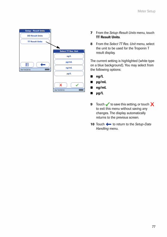
Meter Setup
77
7 From the Setup-Result Units menu, touch TT Result Units.
8 From the Select TT Res. Unit menu, select the unit to be used for the Troponin T result display.
The current setting is highlighted (white type on a blue background). You may select from the following options:
■ ng/L
■ pg/mL
■ ng/mL
■ μg/L
9 Touch to save this setting, or touch to exit this menu without saving any changes. The display automatically returns to the previous screen.
10 Touch to return to the Setup-Data Handling menu.
TT Result Units
Setup - Result Units
DD Result Units
04/19/2016
ng/L
ng/mL
µg/L
Select TT Res. Unit
pg/mL
04/19/2016

Meter Setup
78
Result display mode
Test results may be displayed either with a static or a flashing display, the latter visually indicat-ing that the measurement process has been finished. Once a result is available, the display starts flashing. Depending on the settings, this may be either a quantitative or qualitative result screen or an operator login screen.
1 From the Main Menu, touch Setup to open the meter settings.
2 From the Setup menu, touch Data Handling.
3 From the Setup-Data Handling menu, touch Result Display Mode.
Main Menu
Control Test
Review Results
Setup
Patient Test
09:15 am
04/19/2016
Data Handling
ID Setup
Lockout
Basics
Optional Screens
Setup
04/19/2016
Result Memory
Result Units
Result Display Mode
Setup - Data Handling
Connection
04/19/2016
Diagnostics
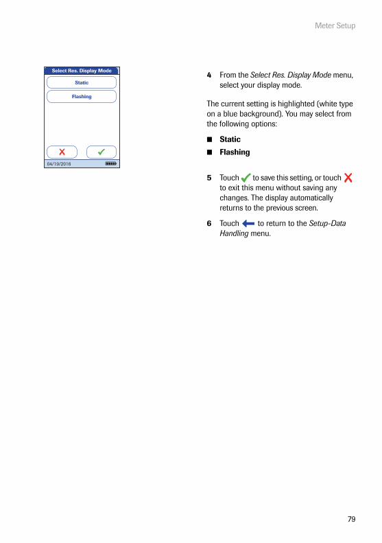
Meter Setup
79
4 From the Select Res. Display Mode menu, select your display mode.
The current setting is highlighted (white type on a blue background). You may select from the following options:
■ Static
■ Flashing
5 Touch to save this setting, or touch to exit this menu without saving any changes. The display automatically returns to the previous screen.
6 Touch to return to the Setup-Data Handling menu.
Flashing
Select Res. Display Mode
Static
04/19/2016

Meter Setup
80
Diagnostics
Under Diagnostics, you will find information about the system, such as software version and wireless configuration details. The Diagnostics menu contains functions relevant for installation, maintenance and troubleshooting purposes. In case of technical problems the firmware version (Build) is an important information for the Roche Diagnostics customer support.
The diagnostics screens shown here are for illustration purposes only. The Information shown on your meter may differ.
1 From the Main Menu, touch Setup to open the meter settings.
2 From the Setup menu, touch Data Handling.
3 From the Setup-Data Handling menu, touch Diagnostics.
Main Menu
Control Test
Review Results
Setup
Patient Test
09:15 am
04/19/2016
Data Handling
ID Setup
Lockout
Basics
Optional Screens
Setup
04/19/2016
Result Memory
Result Units
Result Display Mode
Setup - Data Handling
Connection
04/19/2016
Diagnostics

Meter Setup
81
4 From the Diagnostics menu, touch the button of the diagnostics screen you want to display.
5 Use and to toggle between the Wireless Setup screens.
6 In either diagnostics screen, touch to return to the Diagnostics menu.
Note: The Wireless Setup button is only available if the meter is equipped with WLAN functionality.
Use DNS:
Use DHCP:Enabled
Disabled
SSID:cobas h 232
WLAN:
01 23 45 67 89 AB
Wireless Setup - Network
Wireless Setup
MAC:
04/19/2016
Wireless Setup
Diagnostics
Software
04/19/2016
Software
Build:
Boot:
MM-FW:
MM-BL:
App:
RootFS:
Kernel:
04.00.00
06.03.00
03.00.00
03.00.00
04.00.00
06.03.00
06.03.00
04/19/2016
DMS Port Number:
DMS Name:POCTServer
4711
DMS IP Address:0.0.0.0
RF Security:WPA2-PSK (AES)
Wireless Setup - Connection
Wireless Setup
04/19/2016
TestAuthenticated:
RF activated:Associated:
Confi gured IP:IP:Subnet:Gateway:DNS:Contacted DMS:Connected to DMS:Completed:
255.255.255.0
Wireless Setup - Test
Wireless Setup
192.168.0.123
04/19/2016

Meter Setup
82
3.3 ID Setup setting
Use the ID Setup menu to enter settings for user management and patient management. These settings are optional and set to Off/Inactive by default; the meter can be operated without these settings.
There are three types of identification used with the meter:
■ System Administrator: The administrator has special rights to enter certain meter set-tings and is the only one who can enter and change these settings. It is not necessary for administrator identification to be activated to use the cobas h 232 meter. However, it might be desired or necessary, depending on the regulatory environment and the site of use.
■ Operator: The Operator ID is assigned to persons who use the meter to run tests. If you want to use Operator IDs, you have several options:
– You may use Operator IDs to restrict the use of the meter to qualified personnel or a predefined group of users. In this case an operator list created on a DMS must be trans-ferred to the meter, enabling you to select an Operator ID when logging in. For more details see “Data handling”, starting on page 163.
– You may use Operator IDs for informational purposes only, in order to assign stored measurement results to the users who performed the test. In this case Operator IDs may directly be entered on the meter (by keypad or scanner), with or without an operator list being available.
■ Patient: The Patient ID is assigned to the person, whose test results are recorded. You can either:
– block input of a unique Patient ID (in this case, every test is simply numbered in consecutive order)
– allow a unique Patient ID as optional, or
– require a unique Patient ID for every test. Patient lists created on a DMS can also be trans-ferred to the meter, enabling you to select Patient IDs for a test from these lists. For more details see “Data handling”, starting on page 163.
Operator IDs can be selected from a list (if available) or read by the barcode scanner. If pass-words were created, they must be entered via the onscreen keypad. Patient IDs can be entered by using the onscreen keypad or the barcode scanner.
Meter Setup
83
Administrator ID
In the default setting, the meter is not protected with an Administrator ID, and all setup options are accessible to every user. If you set up an Administrator ID, the following setup areas are auto-matically reserved only for the administrator (i.e., the person who knows the password):
■ Screen: Date/Time
■ Data Handling
■ ID Setup
■ Quality control and the associated lockouts
■ Optional screens
The setup of an Administrator ID does not limit or alter the usage of the meter for measurements in any way. Furthermore setting up the Administrator ID has no impact on the usage of Operator IDs. Only the setup options as listed above are tied to administrator access.
When you enter an Administrator ID, this ID must be entered from this point forward before any future IDs can be set up (anywhere in the ID Setup menu). The Administrator ID must also be entered before you can delete or change the Administrator ID.
If you forget the Administrator ID, the meter setup may be unlocked via the external data man-agement system (e.g., cobas IT 1000). If you don’t use such a system and need to reset the Administrator ID, contact your Roche representative (see Chapter 10).

Meter Setup
84
If an Administrator ID has not been set up yet:
1 From the Main Menu, touch Setup to open the meter settings.
2 From the Setup menu, touch ID Setup.
3 From the Setup-ID Setup menu, touch Administrator ID.
Main Menu
Control Test
Review Results
Setup
Patient Test
09:15 am
04/19/2016
Data Handling
ID Setup
Lockout
Basics
Optional Screens
Setup
04/19/2016
Operator ID
Patient ID
Administrator ID
Setup - ID Setup
04/19/2016

Meter Setup
85
4 Using the onscreen keypad, enter the Administrator ID of choice (or the pass-word provided by Roche Diagnostics). The ID can consist of up to 20 alpha-numeric characters.
Alphanumeric characters are any combi-nation of A - Z and 0 - 9. Additionally “.” (period), or “-” (hyphen) may be used.
Pay close attention to the buttons you press, because the characters are not displayed on the screen. Asterisks are displayed instead (as if entering a password on a computer).
5 Use to switch to the input of numbers.
6 Use to switch back to the input of text.
7 Use to backspace and correct a mistake.
8 Touch to save this Administrator ID, or touch to exit this menu without saving any changes.
A
****|B C D E
F G H I J
K L M N O
P Q R S T
U V W X Y
Z 123
Enter Administrator ID
Enter Administrator ID
0 1 2 3 4
5 6 7 8 9
ABC
****|
123
ABC
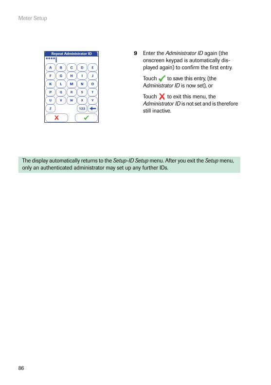
Meter Setup
86
9 Enter the Administrator ID again (the onscreen keypad is automatically dis-played again) to confirm the first entry.
Touch to save this entry, (the Administrator ID is now set), or
Touch to exit this menu, the Administrator ID is not set and is therefore still inactive.
The display automatically returns to the Setup-ID Setup menu. After you exit the Setup menu, only an authenticated administrator may set up any further IDs.
Repeat Administrator ID
A
****|B C D E
F G H I J
K L M N O
P Q R S T
U V W X Y
Z 123

Meter Setup
87
Changing an existing Administrator ID:
1 From the Main Menu, touch Setup to open the meter settings.
2 From the Setup menu, touch ID Setup.
3 Using the onscreen keypad, enter the valid Administrator ID.
The ID Setup is displayed. The Adminis-trator ID button is highlighted, which means an Administrator ID is active.
4 Touch Administrator ID and use the onscreen keypad to enter a new ID of choice (enter it twice).
Main Menu
Control Test
Review Results
Setup
Patient Test
09:15 am
04/19/2016
Data Handling
ID Setup
Lockout
Basics
Optional Screens
Setup
04/19/2016
A
****|B C D E
F G H I J
K L M N O
P Q R S T
U V W X Y
Z 123
Enter Administrator ID
Operator ID
Patient ID
Administrator ID
Setup - ID Setup
04/19/2016

Meter Setup
88
Disabling an existing Administrator ID:
1 From the Main Menu, touch Setup to open the meter settings.
2 From the Setup menu, touch ID Setup.
3 Using the onscreen keypad, enter the valid Administrator ID.
The ID Setup is displayed. The Adminis-trator ID button is highlighted, which means an Administrator ID is active.
4 Touch Administrator ID.
5 Touch to close the onscreen keypad without entering an ID number.
The Administrator ID has been deleted and therefore deactivated. The Adminis-trator ID button is no longer highlighted.
Main Menu
Control Test
Review Results
Setup
Patient Test
09:15 am
04/19/2016
Data Handling
ID Setup
Lockout
Basics
Optional Screens
Setup
04/19/2016
A
****|B C D E
F G H I J
K L M N O
P Q R S T
U V W X Y
Z 123
Enter Administrator ID
Operator ID
Patient ID
Administrator ID
Setup - ID Setup
04/19/2016
A
|B C D E
F G H I J
K L M N O
P Q R S T
U V W X Y
Z 123
Enter Administrator ID

Meter Setup
89
Operator ID
In the default setting, the Operator login is not activated. You can either activate or deactivate Operator login on the meter. If activated, an Operator has to log in before the Main Menu will be displayed and measurements can be performed. Without a list, operators can log in directly by entering their operator name. This setup menu allows you to select whether or not an operator login is possible or required.
1 From the Main Menu, touch Setup to open the meter settings.
2 From the Setup menu, touch ID Setup.
3 From the Setup-ID Setup menu, touch Operator ID.
You may select from the following options:
■ Off (Operator ID cannot be entered)
■ Optional (Operator ID can be entered, but is not required)
■ Required (An Operator ID must be entered)
■ Scan Only (An Operator ID must be scanned)
Main Menu
Control Test
Review Results
Setup
Patient Test
09:15 am
04/19/2016
Data Handling
ID Setup
Lockout
Basics
Optional Screens
Setup
04/19/2016
Operator ID
Patient ID
Administrator ID
Setup - ID Setup
04/19/2016

Meter Setup
90
4 Touch the button with the setting of choice. Your selection is now highlighted.
5 Touch to save this setting, or touch to exit this menu without saving any changes. The display automatically returns to the previous screen or (depend-ing on the option you selected) proceeds to the next screen.
The entries for the option Off are now completed. For the options Optional and Required, continue by selecting the input format.
Operator ID
Patient ID
Administrator ID
Setup - ID Setup
04/19/2016
Select Operator ID
Off
Optional
Required
Scan Only
04/19/2016
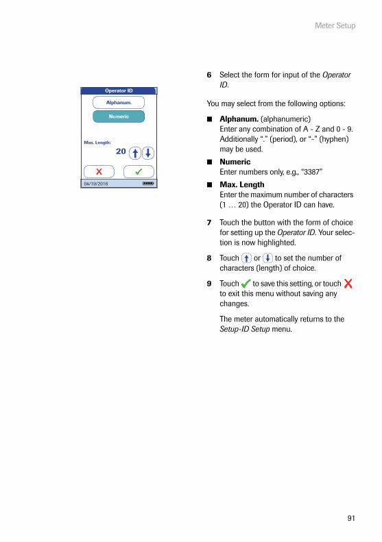
Meter Setup
91
6 Select the form for input of the Operator ID.
You may select from the following options:
■ Alphanum. (alphanumeric) Enter any combination of A - Z and 0 - 9. Additionally “.” (period), or “-” (hyphen) may be used.
■ Numeric Enter numbers only, e.g., “3387”
■ Max. Length Enter the maximum number of characters (1 … 20) the Operator ID can have.
7 Touch the button with the form of choice for setting up the Operator ID. Your selec-tion is now highlighted.
8 Touch or to set the number of characters (length) of choice.
9 Touch to save this setting, or touch to exit this menu without saving any changes.
The meter automatically returns to the Setup-ID Setup menu.
Operator ID
Alphanum.
Numeric
Max. Length:
20
04/19/2016

Meter Setup
92
With an Operator list being transferred to the meter, the Operator ID options are different from the options in “standalone” mode.
If you want to create a list of Operator IDs from which you can select an operator, additional software (a data management system) and a WLAN connection or the Handheld Base Unit are required (for more details see “Data handling”, starting on page 163).
1 From the Main Menu, touch Setup to open the meter settings.
2 From the Setup menu, touch ID Setup.
3 From the Setup-ID Setup menu, touch Operator ID.
You may select from the following options:
■ List (Operator ID must be selected from the list or scanned using the barcode scanner)
■ None (Operator ID cannot be entered or selected)
■ Hidden List (Operator ID must be entered using the barcode scanner or the onscreen keypad)
4 Touch the button with the setting of choice. Your selection is now highlighted.
5 Touch to save this setting, or touch to exit this menu without saving any changes. The display automatically returns to the previous screen.
Main Menu
Control Test
Review Results
Setup
Patient Test
09:15 am
04/19/2016
Data Handling
ID Setup
Lockout
Basics
Optional Screens
Setup
04/19/2016Operator ID
Patient ID
Administrator ID
Setup - ID Setup
04/19/2016
Select Operator ID
List
None
Hidden List
04/19/2016

Meter Setup
93
Patient ID
Patient IDs help you to assign stored results to individual patients. In the default setting, input of Patient IDs is set to No. This means that a consecutive number is assigned to each test. However, you can require that a Patient ID must be entered or make it optional.
If you want to create a list of Patient IDs from which you can select a patient for testing, addi-tional software (a data management system) and a WLAN connection or the Handheld Base Unit are required (see page 163).
1 From the Main Menu, touch Setup to open the meter settings.
2 From the Setup menu, touch ID Setup.
3 From the Setup-ID Setup menu, touch Patient ID.
You may select from the following options:
■ Off (Patient ID cannot be entered)
■ Optional (Patient ID can be entered, but is not required)
■ Required (The operator must enter the Patient ID)
■ Hidden List (Only available when work-ing with a DMS. The list will not be shown. The operator needs to enter the Patient ID manually or via barcode scan.)
Main Menu
Control Test
Review Results
Setup
Patient Test
09:15 am
04/19/2016
Data Handling
ID Setup
Lockout
Basics
Optional Screens
Setup
04/19/2016
Operator ID
Patient ID
Administrator ID
Setup - ID Setup
04/19/2016

Meter Setup
94
4 Touch the button with the setting of choice. Your selection is now highlighted.
5 Touch to save this setting, or touch to exit this menu without saving any changes. The display automatically returns to the previous screen or (depend-ing on the option you selected) proceeds to the next screen.
The entries for the option Off are now completed. For the options Optional and Required, continue by selecting the input format.
Operator ID
Patient ID
Administrator ID
Setup - ID Setup
04/19/2016
Off
Optional
Required
Hidden List
Select Patient ID
04/19/2016

Meter Setup
95
6 Select the form for input of the Patient ID before each test.
You may select from the following options:
■ Alphanum. (alphanumeric) Enter any combination of A - Z and 0 - 9. Additionally “.” (period), or “-” (hyphen) may be used.
■ Numeric Enter numbers only, e.g., “3387”
■ Max. Length Enter the maximum number of characters (1 … 20) the Patient ID can have.
7 Touch the button with the form of choice for the Patient ID. Your selection is now highlighted.
8 Touch or to set the number of characters (length) of choice.
9 Touch to save this setting, or touch to exit this menu without saving any changes.
The display automatically returns to the Setup-ID Setup menu.
Alphanum.
Numeric
Max. Length:
20
Patient ID
04/19/2016

Meter Setup
96
3.4 Lockout setup
The Lockout menu contains the options for quality control tests that the operator is required to perform at specified intervals or based on specific triggers. This is a list of the available lockout options:
■ Operator Lockout
■ QC Settings, containing
– New Lot Lockout– QC Lockout– IQC Lockout– Custom Range Trop T
■ Cleaning Lockout
■ STAT Test Config. (overriding a lockout in an emergency situation)
If the quality control test is not performed as required or if the result is outside the target value range, the meter, parameter or test strip lot is locked from further use. Lockouts can also be set up on an operator-specific basis, i.e., each operator must perform the corresponding quality con-trol tests at specified intervals.
A quality control test must be completed successfully before the meter is made available again (either to the operator or in general) for testing.
The option of setting up lockouts for operators is available only when the meter is set up for operator logins (see page 89) and operator lists are stored in the meter.
In case of an emergency, there may not be the time to first complete the required quality control test if a lockout has been triggered and the meter is "locked". For such cases you may set up so-called STAT Tests (STAT = Short TurnAround Time). This option allows to perform a limited number of tests when an operator lockout or QC lockout is in force. However, once the defined number of STAT tests has been performed, further use of the meter is no longer possible (for the affected test parameter or operator), unless the required quality control test is successfully completed.
STAT tests cannot be performed if IQC lockout is in place or a new lot has not (yet) passed a quality control test (New Lot Lockout).

Meter Setup
97
Operator lockout
To perform a test with the meter, the individual steps must be performed properly. Quality control tests can be performed on a regular basis by every operator to ensure these steps are performed properly. By activating the operator lockout, operators are required to perform regular quality control tests.
1 From the Main Menu, touch Setup to open the meter settings.
2 From the Setup menu, touch Lockout.
3 From the Setup-Lockout menu, touch Operator Lockout.If this button appears in gray (inactive), the option Operator ID is deactivated.
Main Menu
Control Test
Review Results
Setup
Patient Test
09:15 am
04/19/2016 Data Handling
ID Setup
Lockout
Basics
Optional Screens
Setup
04/19/2016
QC Settings
Cleaning Lockout
STAT Test Confi g.
Operator Lockout
Setup - Lockout
04/19/2016

Meter Setup
98
4 Select the time interval of choice in which the required quality control tests must be performed.
You may select from the following options:
■ No (deactivated)
■ Daily
■ Weekly
■ Monthly
■ Every 3 or 6 months
■ Yearly
5 Touch or to display the option of choice on the screen. If the arrow is just an outline , this means no other options are available in the direction indi-cated.
6 Touch the button to select the time interval of choice. Your selection is now high-lighted.
7 Touch to save this setting, or touch to exit this menu without saving any changes.
If you selected No, Operator Lockout is deactivated.
No
Daily
Weekly
Monthly
Every 3 Months
Select Operator Lockout
04/19/2016
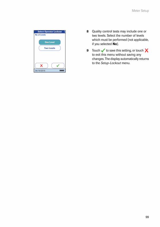
Meter Setup
99
8 Quality control tests may include one or two levels. Select the number of levels which must be performed (not applicable, if you selected No).
9 Touch to save this setting, or touch to exit this menu without saving any changes. The display automatically returns to the Setup-Lockout menu.
Two Levels
One Level
No of Levels
Select Operator Lockout
04/19/2016

Meter Setup
100
Quality control (QC) settings
QC Settings define that operator-independent quality control tests must be run on a regular basis. Lockouts may be triggerd by selectable time periods, and lockouts may be triggered by certain events. The QC Settings menu contains the following options:
■ QC Lockout (time-based), with the additional option of a New Lot Lockout (applies every time a new test strip lot is used)
■ IQC Lockout (time-based)
■ Custom Range Trop. T (customize the QC Range in accordance with applicable local guidelines)
■ QC Result Format (select the format for QC result displays)
■ Reset Test Param. (reset all test parameters, including code chip data and QC lockouts)

Meter Setup
101
1 From the Main Menu, touch Setup to open the meter settings.
2 From the Setup menu, touch Lockout.
3 From the Setup-Lockout menu, touch QC Settings.
Main Menu
Control Test
Review Results
Setup
Patient Test
09:15 am
04/19/2016 Data Handling
ID Setup
Lockout
Basics
Optional Screens
Setup
04/19/2016
QC Settings
Cleaning Lockout
STAT Test Confi g.
Operator Lockout
Setup - Lockout
04/19/2016
QC Lockout
IQC Lockout
QC Result Format
Custom Range Trop. T
Reset Test Param.
Setup - QC Settings
04/19/2016
Meter Setup
102
Quality control (QC) lockout
A QC Lockout requires a quality control test to be performed. You may also set the number of levels for this test. You may select from the following options:
■ New Lot: Yes/No (applies every time a new test strip lot is used)
The general intervals are:
■ No
■ Daily
■ Weekly
■ Monthly
All enabled QC Lockouts, if the time period has elapsed, are activated at 8:00 a.m. (default set-ting, time can be changed with a DMS).
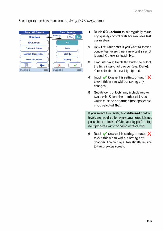
Meter Setup
103
See page 101 on how to access the Setup-QC Settings menu.
1 Touch QC Lockout to set regularly recur-ring quality control tests for available test parameters.
2 New Lot: Touch Yes if you want to force a control test every time a new test strip lot is used. Otherwise touch No.
3 Time intervals: Touch the button to select the time interval of choice (e.g., Daily). Your selection is now highlighted.
4 Touch to save this setting, or touch to exit this menu without saving any changes.
5 Quality control tests may include one or two levels. Select the number of levels which must be performed (not applicable, if you selected No).
If you select two levels, two different control levels are required for every parameter. It is not possible to unlock a QC lockout by performing multiple tests with the same control level.
6 Touch to save this setting, or touch to exit this menu without saving any changes. The display automatically returns to the previous screen.
QC Lockout
IQC Lockout
QC Result Format
Custom Range Trop. T
Reset Test Param.
Setup - QC Settings
04/19/2016
Setup - Lockout
New Lot:Yes No
Daily
Weekly
Monthly
No
04/19/2016

Meter Setup
104
Instrument quality control (IQC) lockout
An IQC Lockout also requires a quality control test with dedicated IQC test strips to be per-formed. You may select from the following options:
■ No
■ Daily
■ Weekly
■ Monthly
All enabled IQC Lockouts, if the time period has elapsed, are activated at 8:00 a.m. (default set-ting, time can be changed with a DMS).
See page 101 on how to access the Setup-QC Settings menu.
1 Touch IQC Lockout to set regularly recur-ring instrument quality control tests (IQC = Instrument Quality Control).
2 Touch the button to select the time interval of choice. Your selection is now high-lighted.
3 Touch to save this setting, or touch to exit this menu without saving any changes. The display automatically returns to the previous screen.
QC Lockout
IQC Lockout
QC Result Format
Custom Range Trop. T
Reset Test Param.
Setup - QC Settings
04/19/2016
No
Daily
Weekly
Monthly
Select IQC Lockout
04/19/2016
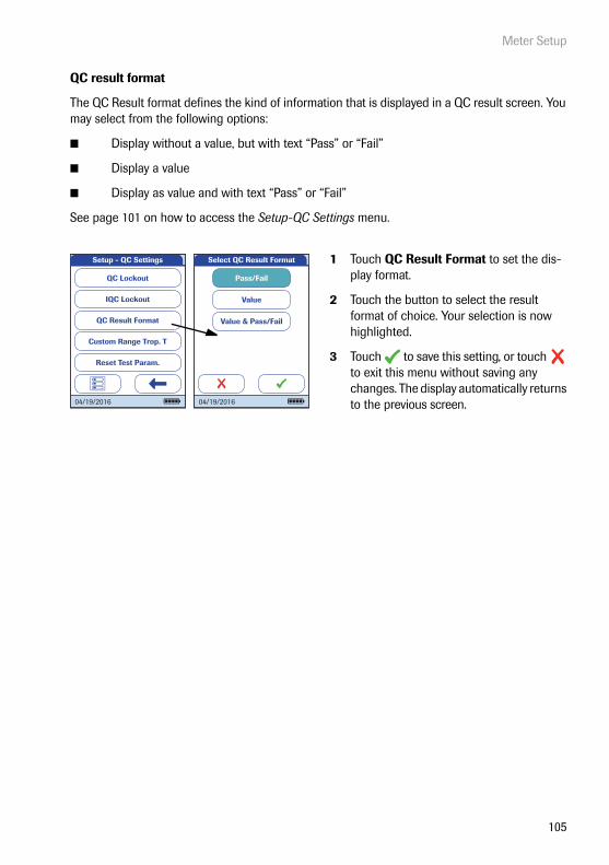
Meter Setup
105
QC result format
The QC Result format defines the kind of information that is displayed in a QC result screen. You may select from the following options:
■ Display without a value, but with text “Pass” or “Fail”
■ Display a value
■ Display as value and with text “Pass” or “Fail”
See page 101 on how to access the Setup-QC Settings menu.
1 Touch QC Result Format to set the dis-play format.
2 Touch the button to select the result format of choice. Your selection is now highlighted.
3 Touch to save this setting, or touch to exit this menu without saving any changes. The display automatically returns to the previous screen.
QC Lockout
IQC Lockout
QC Result Format
Custom Range Trop. T
Reset Test Param.
Setup - QC Settings
04/19/2016
Pass/Fail
Value
Value & Pass/Fail
Select QC Result Format
04/19/2016
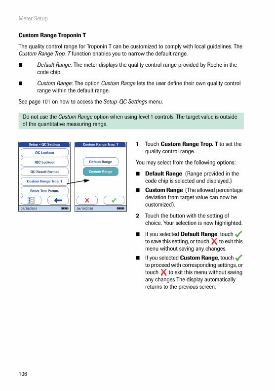
Meter Setup
106
Custom Range Troponin T
The quality control range for Troponin T can be customized to comply with local guidelines. The Custom Range Trop. T function enables you to narrow the default range.
■ Default Range: The meter displays the quality control range provided by Roche in the code chip.
■ Custom Range: The option Custom Range lets the user define their own quality control range within the default range.
See page 101 on how to access the Setup-QC Settings menu.
Do not use the Custom Range option when using level 1 controls. The target value is outside of the quantitative measuring range.
1 Touch Custom Range Trop. T to set the quality control range.
You may select from the following options:
■ Default Range (Range provided in the code chip is selected and displayed.)
■ Custom Range (The allowed percentage deviation from target value can now be customized).
2 Touch the button with the setting of choice. Your selection is now highlighted.
■ If you selected Default Range, touch to save this setting, or touch to exit this menu without saving any changes.
■ If you selected Custom Range, touch to proceed with corresponding settings, or touch to exit this menu without saving any changes The display automatically returns to the previous screen.
QC Lockout
IQC Lockout
QC Result Format
Custom Range Trop. T
Reset Test Param.
Setup - QC Settings
04/19/2016
Custom Range
Default Range
Custom Range Trop. T
04/19/2016

Meter Setup
107
If you selected Custom Range, the Custom Range screen opens and offers you the option of customizing the deviation from target value (percentage value).
For the control solutions, the target value always comes from the information stored in the code chip. If you have chosen Custom Range, you can now select an allowed devia-tion from target value in the range of 0 to 50% (in the illustration, 21%).
3 Use the arrows to to set the allowed per-centage deviation from the target value.
■ Touch to save this setting, or touch to exit this menu without saving any changes. The display automatically returns to the previous screen.
Custom Range
Default Range
Custom Range Trop. T
04/19/2016
Custom Range Trop. T
Deviation from target value (in %):
21
04/19/2016

Meter Setup
108
Reset test parameters
Under certain circumstances, it may be necessary to delete the test parameters stored in the meter (for example, if a lockout exists for a test strip lot that is no longer available). However, do not use this method for overriding lockouts in general because, after resetting the test parame-ters, the meter may go into a QC lockout (if configured). If the meter or a parameter is locked by a QC lockout or an operator lockout, use STAT tests for emergency tests. STAT tests cannot be performed if IQC lockout is in place or a new lot has not (yet) passed a quality control test (New Lot Lockout).
See page 101 on how to access the Setup-QC Settings menu.
4 Touch Reset Test Param. to reset all stored test parameters and QC lockouts.
5 Select Do Reset and confirm by touching to reset the test parameters, or touch to exit without resetting the test parameters (this leads to the same result as selecting and confirming No Reset). The display automatically returns to the previous screen.
QC Lockout
IQC Lockout
QC Result Format
Custom Range Trop. T
Reset Test Param.
Setup - QC Settings
04/19/2016
No Reset
Do Reset
Reset Test Parameter
04/19/2016

Meter Setup
109
Cleaning lockout
Under normal handling conditions, your meter will not be exposed to significant dirt or contami-nation. However, circumstances might require regular checks of the test strip guide and (when necessary) cleaning of the meter. The Cleaning Lockout allows operators to specify time intervals for cleaning.
1 From the Main Menu, touch Setup to open the meter settings.
2 From the Setup menu, touch Lockout.
3 From the Setup-Lockout menu, touch Cleaning Lockout.
You may select from the following options:
■ No
■ Daily
■ Weekly
■ Monthly
4 Touch the button to select the time interval of choice. Your selection is now high-lighted.
5 Touch to save this setting, or touch to exit this menu without saving any changes. The display automatically returns to the previous screen.
Main Menu
Control Test
Review Results
Setup
Patient Test
09:15 am
04/19/2016 Data Handling
ID Setup
Lockout
Basics
Optional Screens
Setup
04/19/2016
QC Settings
Cleaning Lockout
STAT Test Confi g.
Operator Lockout
Setup - Lockout
04/19/2016Daily
Weekly
Monthly
No
Select Cleaning Lockout
04/19/2016

Meter Setup
110
STAT test configuration
Quality control tests ensure consistent quality and accurate measurements. In emergency situa-tions, however, it may be necessary to perform a test without delay. To override an active lockout for a test parameter, lot or operator, you can allow for STAT Tests (STAT = Short TurnAround Time). STAT tests cannot be performed if IQC lockout is in place or a new lot has not (yet) passed a quality control test (New Lot Lockout).
You can set a number of tests permitted beyond the lockout. Once the number of allowed STAT Tests has been reached (for a single parameter), additional tests for this parameter are locked until you successfully perform a quality control test.
STAT tests are labelled accordingly in the result window.
STAT Tests will be counted separately for each test parameter. Thus the actual availability of STAT Tests may differ for each parameter.
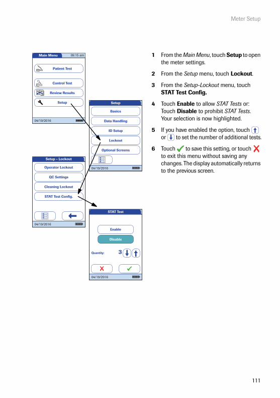
Meter Setup
111
1 From the Main Menu, touch Setup to open the meter settings.
2 From the Setup menu, touch Lockout.
3 From the Setup-Lockout menu, touch STAT Test Config.
4 Touch Enable to allow STAT Tests or:Touch Disable to prohibit STAT Tests.Your selection is now highlighted.
5 If you have enabled the option, touch or to set the number of additional tests.
6 Touch to save this setting, or touch to exit this menu without saving any changes. The display automatically returns to the previous screen.
Main Menu
Control Test
Review Results
Setup
Patient Test
09:15 am
04/19/2016 Data Handling
ID Setup
Lockout
Basics
Optional Screens
Setup
04/19/2016
QC Settings
Cleaning Lockout
STAT Test Confi g.
Operator Lockout
Setup - Lockout
04/19/2016
Disable
Enable
Quantity: 3
STAT Test
04/19/2016
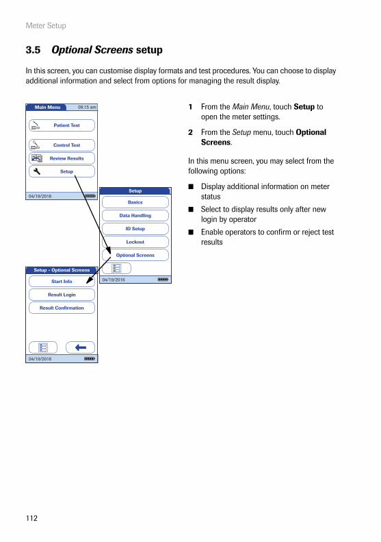
Meter Setup
112
3.5 Optional Screens setup
In this screen, you can customise display formats and test procedures. You can choose to display additional information and select from options for managing the result display.
1 From the Main Menu, touch Setup to open the meter settings.
2 From the Setup menu, touch Optional Screens.
In this menu screen, you may select from the following options:
■ Display additional information on meter status
■ Select to display results only after new login by operator
■ Enable operators to confirm or reject test results
Main Menu
Control Test
Review Results
Setup
Patient Test
09:15 am
04/19/2016
Data Handling
ID Setup
Lockout
Basics
Optional Screens
Setup
04/19/2016
Setup - Optional Screens
Result Login
Result Confi rmation
Start Info
04/19/2016

Meter Setup
113
The additional status information is displayed after powering on the meter or after logging off as an operator. This includes information about current lockouts, the number of results not trans-ferred (to the DMS) and the time since the last data transfer.
In environments with multiple operators, it can be useful to display a test only if the operator carrying out the test is present. By requiring operators to login again before displaying results, you ensure that only authorised persons view the results.
3 Touch Start Info.
4 Touch the button to select the state of the status display. Your selection is now high-lighted.
5 Touch to save this setting, or touch to exit this menu without saving any changes.
6 Touch Result Login.
7 Touch the button to select the state of the option. Your selection is now highlighted.
8 Touch to save this setting, or touch to exit this menu without saving any changes.
Setup - Optional Screens
Result Login
Result Confi rmation
Start Info
04/19/2016
Disable
Enable
Start Info Screen
04/19/2016
Setup - Optional Screens
Result Login
Result Confi rmation
Start Info
04/19/2016
Disable
Enable
Result Login Screen
04/19/2016

Meter Setup
114
In some circumstances, it may be useful for operators to confirm the validity of their results. To do so, an option can be enabled that prompts operators to confirm the results of every test.
9 Touch Result Confirmation.
10 Touch the button to select the state of the option. Your selection is now highlighted.
11 Touch to save this setting, or touch to exit this menu without saving any changes.
Setup - Optional Screens
Result Login
Result Confi rmation
Start Info
04/19/2016
Disable
Enable
Res. Confi rmation Screen
04/19/2016

Performing a Test
115
4 Performing a Test
What you need:
■ Suitable blood sampling system to collect venous whole blood
■ cobas h 232 meter
■ Roche CARDIAC test strips for the desired test, with the supplied code chip
■ Roche CARDIAC pipettes (or other suitable pipettes with pipetting volume of 150 μL) for applying the sample to the test strip
Always …
■ … operate the meter according to the specified operating conditions (see page 183).
■ … follow the information on correct handling of test strips in the package insert.
■ … place the meter on a level, vibration-free surface when applying the sample to the sample application area of the test strip. Once the sample has been completely absorbed by the test strip, you can move the meter.
■ … keep the meter clean. See “Maintenance and Care” on page 169.
Only heparinized blood collection tubes are allowed. Refer to test strip package insert.
The Roche CARDIAC family includes several strips. Always ensure that the disposables you are using (e.g., test strips) are intended for use with the cobas h 232 meter. Some tests might require a minimum software version. Ensure that the software version on the cobas h 232 meter is compatible with the test you are running (refer to the corresponding package insert for details). Contact your Roche representative if the cobas h 232 meter requires a software update.

Performing a Test
116
Never …
■ … use Roche CARDIAC pipettes for collecting blood from the patient.
■ … touch or remove the test strip during a test.
■ … add more blood after the test has begun.
■ … remove or insert the code chip while the meter is performing a test.
■ … move or pick up the meter while applying the sample - wait until the necessary sample has been absorbed completely by the test strip.
■ … store the meter at extreme temperatures.
■ … store the meter in damp or humid conditions without protection.
■ … store the meter in a dusty environment without protection.
CAUTION
Accuracy/precision of measured results:
Failure to comply with the above may lead to inaccurate results. An incor-rect result may lead to an error in diagnosis, therefore posing danger to the patient.

Performing a Test
117
Sample material
4.1 Preparing to test
WARNING
Proper sample collection
In order to avoid false test results which may lead to inaccurate thera-peutic decisions adhere to the following when collecting blood samples:
■ Only use heparinized venous whole blood as sample material.
■ For each test use exactly 150 μL of sample.
■ Use a suitable sampling system to collect the blood sample. Use only heparinized blood collection tubes. Do not use blood collection tubes containing EDTA, citrate, sodium fluoride or other additives. For details refer to the test strip package insert.
IMPORTANT NOTE: Never use Roche CARDIAC pipettes for blood sampling directly from the vein nor for administering injections. They are not sterile-packaged and do not contain anti-coagulants. Roche CARDIAC pipettes are intended only for drawing the sample from the blood collection tube and applying it to the test strip. See page 132.
■ Observe the applicable regulations and directives for hygiene and safety when collecting blood samples.
■ Observe the applicable regulations and directives for disposing of potentially infectious samples and materials.
■ Dispose of used consumables in line with the disposal policy of your hospital, institute or medical practice.
■ See safety message “Protection against infection and blood-borne pathogens” on page 15.
1 Prepare the required test strips (shown here: Roche CARDIAC POC for testing Troponin T).
2 Make sure that the code chip supplied with these test strips is also at hand.

Performing a Test
118
Code chip
The code chip provides the meter with important information on the manufacturer-specific parameters of the respective test strip lots. It contains information about the test method, the lot number and the expiration date.
■ Each test strip box contains its own code chip. Make sure you have the code chip at hand before performing the first test with a new test strip lot.
■ When you insert a test strip from a new lot for the first time, the meter prompts you to insert the corresponding code chip. At this point, compare the code number you see on the display with the number that is printed on the test strip package you are using. If the two code numbers are identi-cal, insert the new code chip into the slot in the meter.
■ Once inserted, the code chip information is read and stored on the meter. The meter can store up to 200 code chip datasets (100 test strip lots and 100 quality control lots). Further tests using the same strip lot can be performed without inserting the code chip again.
■ The code chip is no longer required, once the data is stored. You may leave it in the meter, or you can use it with other meters using the same test strip lot.
Pat. Test - Ins. Chip
Insert Code Chip
proBNPPar:
04/19/2016
2721

Performing a Test
119
Inserting the code chip
Roche recommends keeping the code chip in the meter to protect the contacts from becoming dirty. Protect the code chip from moisture and equipment which produces magnetic fields and electrostatic discharges. Once the test strip lot is used up, dispose of the old code chip promptly to prevent mix-ups.
1 Remove the old code chip, if one is inserted in the meter.
2 Always make sure that the number on the code chip matches the number on the label of the test strip package.
By scanning the barcode on the strip, the meter gathers information about the number of the required code chip.
3 Slide the new code chip into the slot on the top of the meter as shown until you feel it snaps into place.
If the code chip does not match the test strip lot, is missing or incorrectly inserted, an error message appears in the display (see “Troubleshooting” starting on page 179).

Performing a Test
120
Test steps (overview)
The following illustration shows the steps performed during testing. The steps you actively per-form are displayed with a dark background. Depending on the configuration, the individual steps shown here may include additional actions (e.g., entering a password). Some steps may be dif-ferent, working with or without Operator IDs and Patient IDs. On the following pages these steps are explained separately for each configuration.

Performing a Test
121
1 Without operator and patient lists (or both operator and patient ID disabled)
2 With operator list (or operator ID enabled)
3 With operator and patient list (or operator and patient ID enabled)
Powering on
Self-check
Main menu
Patient test
Test strip
Sample
Result
Powering on
Self-check
Main menu
Log in/list
Patient test
Test strip
Sample
Result
Powering on
1 2 3
Self-check
Main menu
Log in/list
Patient test
Patient ID/list
Test strip
Sample
Result
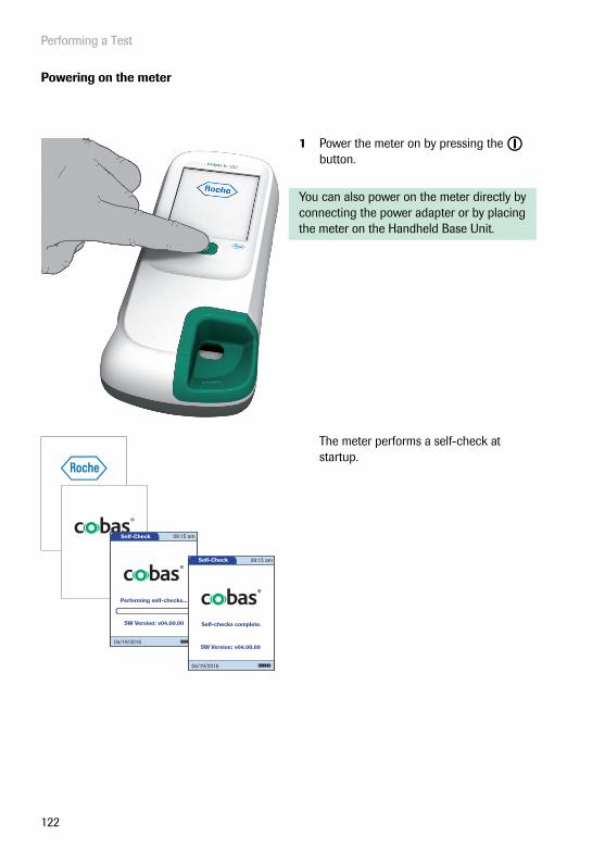
Performing a Test
122
Powering on the meter
1 Power the meter on by pressing the button.
You can also power on the meter directly by connecting the power adapter or by placing the meter on the Handheld Base Unit.
The meter performs a self-check at startup.
Self-Check
Performing self-checks...
04/19/2016
SW Version: v04.00.00
09:15 am
Self-Check
Self-checks complete.
04/19/2016
SW Version: v04.00.00
09:15 am
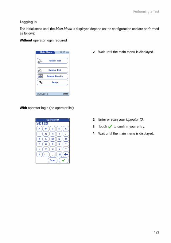
Performing a Test
123
Logging in
The initial steps until the Main Menu is displayed depend on the configuration and are performed as follows:
Without operator login required
With operator login (no operator list)
2 Wait until the main menu is displayed.
2 Enter or scan your Operator ID.
3 Touch to confirm your entry.
4 Wait until the main menu is displayed.
Main Menu
Control Test
Review Results
Setup
Patient Test
09:15 am
04/19/2016
A
SC123B C D E
F G H I J
K L M N O
P Q R S T
U V W X Y
Z , 123
Operator ID
Scan

Performing a Test
124
With operator login (list available)
2 If an operator list exists, wait until this list is displayed.
3 Touch or to scroll through the list. Select the operator of choice by touching the corresponding button.
As an alternative (meters with a scanner), the operator login can be performed via the built-in barcode scanner.
■ Touch Scan
■ Hold the card with the barcode approx. 15 cm (6 in) from the scanner.
It is not possible to connect an external bar-code scanner to the meter.
The scanner equipped cobas h 232 meter described in this manual provides a camera based 2D barcode scanner, instead of the laser scanner used in previous meter versions. Established scanning procedures may need some corresponding adjustments:
■ the nominal distance between scanner and barcode is slightly different
■ avoid reflections on the barcode (e.g. by reflective foils etc.)
■ ensure an adequate size and quality of barcodes
See Appendix A for further details on barcode handling.
OP003Hall, Molly-Jessica
OP001Hughes, Adam
OP002Patel, Alfi e-Adam
Select Operator ID
Scan
04/19/2016

Performing a Test
125
4 Enter the password.
5 Touch to confirm your entry, or touch to display the operator list again.
6 Wait until the main menu is displayed.
When the tests are completed or another operator wants to perform additional tests, touch Logout to log out. The meter returns to the display of the operator list.
A B C D E
F G H I J
K L M N O
P Q R S T
U V W X Y
Z 123
Password
****|
Main Menu
Control Test
Review Results
Setup
Patient Test
Logout
09:15 am
04/19/2016

Performing a Test
126
4.2 Performing a test
1 Check the charge level of the battery pack. If there are no bars left in the battery icon, you cannot perform any more tests. For further details see page 27.
2 Check that the date and time are correct. Correct any incorrect settings as described in the chapter entitled “Meter Setup/Setting the date”.
If a QC lockout is displayed instead of Patient Test, you must run a quality control test before you can perform a test (see “Control Testing and Quality Control” starting on page 141). If the meter is locked, a test can only be performed as a STAT test (if this func-tion is enabled and if there are still STAT tests available).
If a Cleaning Lockout is displayed instead of Patient Test, you must touch Cleaning and follow the instructions on the screen and clean the meter. See “Maintenance and Care” beginning on page 169. Once you have re-attached the test strip guide cover and pow-ered the meter on again, the meter is no longer locked.
If the Patient Test button is available, but a lockout is displayed, you must first perform a quality control test for certain test parameters. Other test parameters are not affected.
Main Menu
Control Test
Review Results
Setup
Patient Test
09:15 am
Logout
04/19/2016
Main Menu
Control Test
Review Results
Setup
QC Lockout
Logout
09:15 am
04/19/2016
Main Menu
Cleaning Lockout
Cleaning
Review Results
Setup
09:15 am
04/19/2016
Clean Meter
Remove Cover
04/19/2016
Main Menu
Control Test
Review Results
Setup
Patient Test
Logout
QC!
09:15
19.04.2016

Performing a Test
127
Without patient list
3 Touch Patient Test.
4 If you selected the Patient ID as optional, you can enter or scan a Patient ID.If you selected the Patient ID as required, you must enter or scan the Patient ID.If you selected no Patient ID (None), the meter automatically proceeds to the next step.
5 Touch to confirm the ID, or touch to cancel the ID entry.
Continue reading on page 130.
A
PID111SCHULZM457
B C D E
F G H I J
K L M N O
P Q R S T
U V W X Y
Z , 123
Patient ID
Scan

Performing a Test
128
With patient list
3 Touch Patient Test.
Patient lists can only be created on a DMS and must be transferred to the meter. Lists cannot be created on the meter.
4 Touch or to scroll through the list. Select the patient to be tested by touching the corresponding button.
5 If the patient is not in the list, touch New to create a new entry. You must now enter a Patient ID manually or scan it using the barcode scanner.
Select Patient ID
New
PID001GERTA123Anders, Gert
PID001CHAPLINC123Chaplin, Charlene
PID001BERNDH123Bernd, Hans
PID001FRENZENA12Frenzen, Alice
PID230ONEALJ1234ONeal, John
Scan
04/19/2016
A
PID111SCHULZM457
B C D E
F G H I J
K L M N O
P Q R S T
U V W X Y
Z , 123
Patient ID
Scan

Performing a Test
129
The Patient ID can also be entered via bar-code (meters with a barcode scanner only). Touch Scan and hold either
■ a card with the barcode approx. 15 cm (6 in) from the scanner or
■ the meter over a patient bracelet.
The scanner is also active, once you open the Enter Patient ID screen using the New button (for approx. 10 seconds).
Select Patient ID
New
PID001GERTA123Anders, Gert
PID001CHAPLINC123Chaplin, Charlene
PID001BERNDH123Bernd, Hans
PID001FRENZENA12Frenzen, Alice
PID230ONEALJ1234ONeal, John
Scan
04/19/2016

Performing a Test
130
Inserting a test strip
1 The test strip icon prompts you to insert a test strip. Remove the test strip from its foil pouch.
2 Hold the test strip so that the application area and test area are facing up.
3 Hold the test strip straight and flat. Insert it in the test strip guide of the meter. Be careful that the strip is not shifted, angled or tilt during insertion. It is also important that you insert the test strip using one smooth movement.
Inserting the test strip too slowly or too fast can cause a barcode reading error.
Slide the test strip in as far as it will go. A beep tone indicates that the meter has detected the test strip (provided the beeper is enabled).
WARNING
Test strip deterioration
Exposure to external influences (e.g., humidity) may deteriorate the test strips and may lead to error messages! Remove the test strip from its foil pouch only when you are ready to perform a test.
Pat. Test - Ins. Strip
Insert Strip
JONES, TOMOp:
PID111SCHULZM457SCHULZ, MANFRED
Pat:
04/19/2016

Performing a Test
131
If you use a new test strip lot, you must insert the corresponding code chip once. See “Code chip” on page 118.
Depending on the meter setting, you may also be required to run a quality control test at this point.
The meter identifies the required code chip based on the test strip barcode and displays the code number.
For each test parameter and each new test strip lot a different code key number is displayed.
The thermometer icon shows that the test strip is warming up. A beep tone indicates when the warming-up process is complete (provided the beeper is enabled).
Pat. Test - Ins. Chip
Insert Code Chip
proBNPPar:
04/19/2016
2721
Pat. Test - Warming Up
Please Wait
Warming Up
PID111SCHULZM457SCHULZ, MANFREDJONES, TOM
Pat:
Op:proBNPPar: PB1234Code:
04/19/2016
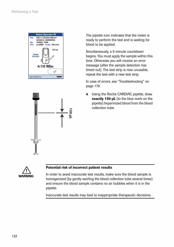
Performing a Test
132
The pipette icon indicates that the meter is ready to perform the test and is waiting for blood to be applied.
Simultaneously, a 5-minute countdown begins. You must apply the sample within this time. Otherwise you will receive an error message (after the sample detection has timed out). The test strip is now unusable, repeat the test with a new test strip.
In case of errors, see “Troubleshooting” on page 179.
4 Using the Roche CARDIAC pipette, draw exactly 150 μL (to the blue mark on the pipette) heparinized blood from the blood collection tube.
WARNING
Potential risk of incorrect patient results
In order to avoid inaccurate test results, make sure the blood sample is homogenized (by gently swirling the blood collection tube several times) and ensure the blood sample contains no air bubbles when it is in the pipette.
Inaccurate test results may lead to inappropriate therapeutic decisions.
Select Operator ID
Apply Sample
4:10
PID111SCHULZM457SCHULZ, MANFREDJONES, TOM
Pat:
Op:proBNPPar:
Min
150 µL
PB1234Code:
04/19/2016
15
0 µ
L

Performing a Test
133
Always place the meter on a level, vibration-free surface when applying the sample to the sample application area of the test strip. Once the sample has been completely absorbed by the test strip, you can move the meter.
CAUTION
5 Apply the entire sample to the sample application area of the test strip.
6 Touch to confirm that the sample has been applied.
The hourglass icon appears as the meter begins to process the sample. For better control over the measurement process, you should always confirm this yourself, instead of waiting for the meter to detect the sample.
After you confirm that the sample has been applied, or if the meter automatically recog-nises that the sample has been applied, the
button disappears.
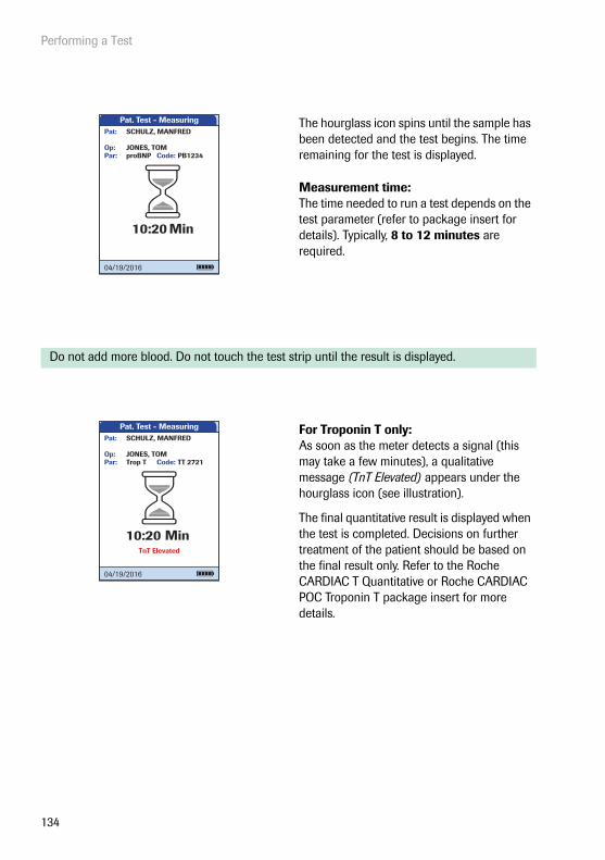
Performing a Test
134
The hourglass icon spins until the sample has been detected and the test begins. The time remaining for the test is displayed.
Measurement time: The time needed to run a test depends on the test parameter (refer to package insert for details). Typically, 8 to 12 minutes are required.
Do not add more blood. Do not touch the test strip until the result is displayed.
For Troponin T only: As soon as the meter detects a signal (this may take a few minutes), a qualitative message (TnT Elevated) appears under the hourglass icon (see illustration).
The final quantitative result is displayed when the test is completed. Decisions on further treatment of the patient should be based on the final result only. Refer to the Roche CARDIAC T Quantitative or Roche CARDIAC POC Troponin T package insert for more details.
Pat. Test - Measuring
proBNP PB1234JONES, TOM
Par:Op:
Code:
SCHULZ, MANFREDPat:
10:20 Min
04/19/2016
Pat. Test - Measuring
Trop T TT 2721JONES, TOM
Par:Op:
Code:
SCHULZ, MANFREDPat:
10:20 MinTnT Elevated
04/19/2016

Performing a Test
135
The test result is shown and stored automati-cally.
When interpreting your result, please read the test strip package insert carefully.
Print button: Print results (infrared interface)
QR Code button: Display result as QR code
Menu button: Return to main menu
Comment button: Add predefined or custom comments to the test result
7 Remove the test strip from the meter.
8 Power the meter off by pressing the button for approximately 1 second if you do not wish to perform any further tests.
9 Discard the used disposable item and test strip in compliance with the disposal policy of your hospital or medical practice.
10 Clean the meter if necessary. See “Main-tenance and Care” on page 169).
Pat. Test - Result
620 pg/mL
proBNP PB1234
SCHULZ, MANFREDJONES, TOM
Par:Op:
Code:
PID111SCHULZM457Pat:
04/19/2016
04/19/2016 10:17
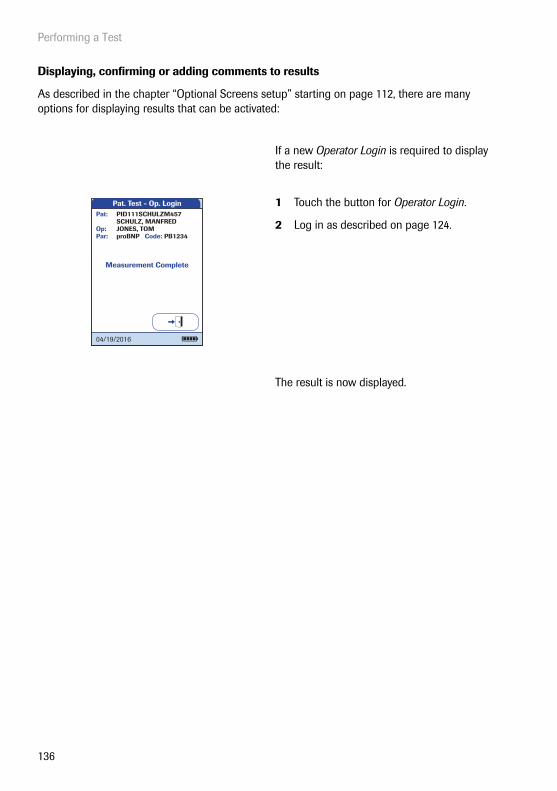
Performing a Test
136
Displaying, confirming or adding comments to results
As described in the chapter “Optional Screens setup” starting on page 112, there are many options for displaying results that can be activated:
If a new Operator Login is required to display the result:
1 Touch the button for Operator Login.
2 Log in as described on page 124.
The result is now displayed.
Pat. Test - Op. Login
Measurement Complete
proBNP PB1234
SCHULZ, MANFREDJONES, TOM
Par:Op:
Code:
PID111SCHULZM457Pat:
04/19/2016

Performing a Test
137
If the test result requires a confirmation:
■ When the result is displayed, touch the button to select the confirmation of choice.
You can choose to either
■ Reject
■ Accept
If you reject the result, the result value is no longer displayed. However, the test entry is stored.
If you miss to finish a required confirmation before the meter is powered off automatically, the test result will be stored and displayed along with a “Result not validated” comment. However, if a confirmation is required, the meter reminds you to do so with a series of triple beeps (once a minute for the last 3 minutes) before powering off.
Pat. Test - Confi rm.
62004/19/2016 10:17
pg/mL
proBNP PB1234
SCHULZ, MANFREDJONES, TOM
Par:Op:
Code:
PID111SCHULZM457Pat:
Measurement OK?
Reject Accept
04/19/2016
Pat. Test - Result
Rejected04/19/2016 10:17
proBNP PB1234
SCHULZ, MANFREDJONES, TOM
Par:Op:
Code:
PID111SCHULZM457Pat:
04/19/2016

Performing a Test
138
You can add up to three comments to a test result. Comments can provide, for example, addi-tional information about the test conditions or the patient. A comment may be up to 20 charac-ters in length. You can open the function for adding comments directly in the results screen.
If you want to add a comment, do not remove the test strip. Once the strip is removed, the meter automatically returns to Main Menu and a comment can no longer be added.
If you want to add a comment to a test result:
1 In the result screen, touch .
2 Select a predefined comment from the list and/or
3 Touch Custom to enter your own com-ment using the onscreen keypad.
The comments are stored with the test result.
Pat. Test - Result
620 pg/mL
proBNP PB1234
SCHULZ, MANFREDJONES, TOM
Par:Op:
Code:
PID111SCHULZM457Pat:
04/19/2016
04/19/2016 10:17
Pat. Test - Comment
Asymptomatic
Chest Pain
Dyspnea
Symptomatic
Custom
04/19/2016
Pat. Test - Result
62004/19/2016 10:17
pg/mL
Par:Op:
Code:
Pat:
Test
SymptomaticChest Pain
04/19/2016
proBNP PB1234
SCHULZ, MANFREDJONES, TOM
PID111SCHULZM457

Performing a Test
139
Displaying the test result as QR code
The QR code button only appears if the QR code display function is activated (see page 65 and following). Otherwise it is not displayed.
1 Touch to display the result as QR code.
2 Touch to return to the standard result display.
The size of the QR code displayed on the screen varies according to the amount of data encoded.
Pat. Test - Result
620 pg/mL
proBNP PB1234
SCHULZ, MANFREDJONES, TOM
Par:Op:
Code:
PID111SCHULZM457Pat:
04/19/2016
04/19/2016 10:17
Pat. Test - Result
04/19/2016

Performing a Test
140
STAT tests
STAT tests are a limited number of tests that can be performed in emergency situations, see page 110. If the meter is configured to perform STAT tests, you have the option of performing a test by choosing STAT even though a QC Lockout is in place.
1 To perform the measurement without performing a quality control test, touch STAT, or:
2 Touch to perform the quality control test before the measurement.
When a STAT test is performed, this infor-mation is stored with the result. The number of permissible STAT tests is reduced by 1. After all pending quality control tests are performed, the specified number of STAT tests is available again in case of a new lockout.
Pat. Test - Lockout
Test Parameter Locked!
Please Perform QC.
PID111SCHULZM457SCHULZ, MANFREDJONES, TOM
Pat:
Op:proBNPPar:
STAT
PB1234Code:
04/19/2016
Pat. Test - Result
620 pg/mL
proBNP PB1234
SCHULZ, MANFREDJONES, TOM
Par:Op:
Code:
PID111SCHULZM457Pat:
STAT Test
04/19/2016
04/19/2016 10:17

Control Testing and Quality Control
141
5 Control Testing and Quality Control
The cobas h 232 meter employs several methods to check that the meter and test strips are wor-king properly and that the operator is performing the test correctly.
The meter has a number of built-in quality control functions:
■ A self-check of the electronic components and functions every time the meter is powered on.
■ A check of test temperature when warming up and during the test.
■ A check of the expiration date and lot information on the test strip using the information from the code chip.
In addition, the cobas h 232 meter provides:
■ Configurable, prescribed quality control tests using Roche CARDIAC IQC test strips for internal functionality tests.
■ Definable, prescribed control tests using Roche CARDIAC Control materials for the avail-able test parameters.

Control Testing and Quality Control
142
Manufacturer recommended frequency of quality control tests:
*only on days when the cobas h 232 meter is used for measurements
Manufacturer recommended use:
QC recommendations by national associations or local hospital guidelines take precedence over manufacturer recommendations
WARNING
Potential risk of incorrect patient results
Failure to check the system regularly by performing quality control tests may lead to incorrect results and therefore to inappropriate therapy deci-sions. To ensure that the system is functioning properly adhere to the manufacturer recommendations on quality control testing given in the tables below.
Frequency Material to test Reason Release criteriaDaily* CARDIAC IQC High
andCARDIAC IQC Low
Verification of the proper functioning of the optical system
Both levels are “Pass”
Frequency Material to test Reason Release criteriaOnce a month
Roche CARDIAC Controls
To verify adequate storage at customer site
Results are within the range provided by the manufacturer
With each new shipment of test strips
To verify proper function-ing after transportation to customer site
When an implausible result is obtained
When an operator uses the cobas h 232 system (meter with or without scanner) for the first time
To qualify the new operator; to verify proper handling and sample dosing
After adverse events such as dropping the meter or other strong mechanical shocks.
Roche CARDIAC Controlsand CARDIAC IQC HighandCARDIAC IQC Low
To verify proper function-ing of the meter
Results are within the range provided by the manufacturer

Control Testing and Quality Control
143
5.1 Preparing to run a quality control test
Prepare for a quality control test in the same way you would prepare to perform a test with a patient sample. The only difference is the use of control solution instead of blood.
To perform a quality control test using control solutions, you need:
■ cobas h 232 meter
■ Test strips for the desired tests, with the supplied code chip
■ Roche CARDIAC pipettes (or other suitable pipettes with pipetting volume of 150 μL)
■ Control set containing two vials of Roche CARDIAC Control material and code chip
You can specify the frequency of quality control tests according to your own requirements (see “Meter Setup/Lockout setup” starting on page 96).
If you encounter a lockout for a test strip lot that no longer exists, see “Reset test parameters” on page 108. Please note that, when you use this method, all saved test parameters and QC lock-outs will be deleted.
Always refer to the package insert provided with the control material for specific handling and testing instructions.
Reconstituted control material taken from the refrigerator must be allowed to reach room temperature before use.

Control Testing and Quality Control
144
5.2 Performing a quality control test
Quality control (QC)
1 Power the meter on by pressing the button.
You can also power on the meter directly by connecting the power adapter or by placing the meter on the Handheld Base Unit.
Depending on the system settings the opera-tor my have to log in and/or enter a password. Follow the procedures as described on page 124.
2 Wait until the main menu is displayed.Main Menu
Control Test
Review Results
Setup
Patient TestQC!
09:15 am
04/19/2016

Control Testing and Quality Control
145
3 Touch Control Test.
4 In the QC Status screen, touch to con-tinue with the quality control test.
5 The test strip icon now prompts you to insert a test strip. Remove the test strip from its foil pouch.
6 Hold the test strip so that the application area and test area are facing up.
7 Hold the test strip straight and flat. Insert it in the test strip guide of the meter. Be careful that the strip is not shifted, angled or tilt during insertion. It is also important that you insert the test strip using one smooth movement.
Inserting the test strip too slowly or too fast can cause a barcode reading error.
Slide the test strip in as far as it will go. A beep tone indicates that the meter has detected the test strip (provided the beeper is enabled).
CAUTION
Test strip deterioration
Exposure to external influences (e.g., humidity) may deteriorate the test strips and may lead to error messages! Remove the test strip from its foil pouch only when you are ready to perform a test.
Main Menu
Control Test
Review Results
Setup
Patient TestQC!
09:15 am
04/19/2016
QC Test - QC Status
CK-MB
QC Status
MyoDDimer
- Pass
- Pass- Pass
Trop TproBNP
- Locked- Locked
04/19/2016
QC Test - Ins. Strip
Insert Strip
JONES, TOMOp:
04/19/2016

Control Testing and Quality Control
146
If you use a new test strip lot and have not inserted the code chip yet, you must do so now. Otherwise you cannot perform a quality control test.
As with the test strips, a code chip is also pro-vided with the control materials. The informa-tion on the code chip is stored in the memory so you can use the same control materials again at any time.
8 Select the code stored for your current control material, or touch New to use a new control material.
If you are using a new control material, remove the code chip from the meter and insert the code chip that came with the control material instead.
QC Test - Sel. QC Lotpro BNP PB1234
JONES,TOM
Par:
Op:
Code:
New
Code PBC014
Code PBC016
Code PBC017
Code PBC018
04/19/2016
QC Test - Ins. Chip
Insert Code Chip
PBC014
proBNP PB1234PBC014JONES, TOM
Par:
Op:
Code:QC:
04/19/2016
QC

Control Testing and Quality Control
147
9 If the control material box contains more than one level, select the level of choice for this measurement.
The thermometer icon shows that the test strip is warming up. A beep tone indicates when the warming-up process is complete (provided the beeper is enabled).
The pipette icon indicates that the meter is ready to perform the test and is waiting for the sample to be applied.
Simultaneously, a 5-minute countdown begins. You must apply the sample within this time, otherwise you will receive an error message (after the sample detection has timed out).
In case of errors, see “Troubleshooting” on page 179.
QC Test - Sel. QC Level
Level 2
Level 1
proBNP PB1234PBC014JONES, TOM
Par:
Op:
Code:QC:
04/19/2016
QC Test - Warming Up
Level: 1proBNP, PB1234PBC014JONES, TOM
Par:
Op:
Code:QC:
04/19/2016
Please Wait
Warming Up
QC Test - App. QC
Apply QC
Min
150 µL
Level: 1proBNP PB1234PBC014JONES, TOM
Par:
Op:
Code:QC:
4:10
04/19/2016

Control Testing and Quality Control
148
Always place the meter on a level, vibration-free surface when applying the sample to the sample application area of the test strip. Once the sample has been completely absorbed by the test strip, you can move the meter.
CAUTION
10 Using the pipette, draw up the dissolved contents of the vial.
11 Apply the sample (exactly 150 μL) to the application area of the test strip.
12 Touch to confirm that the sample has been applied.

Control Testing and Quality Control
149
The hourglass icon appears as the meter begins to process the sample. For better control over the measurement process, you should always confirm this yourself, instead of waiting for the meter to detect the sample.
13 After you confirm that the sample has been applied, or if the meter automatically recognises that the sample has been applied, the button disappears.
The hourglass icon spins until the sample has been detected and the test begins. Unlike regular tests, this procedure can be very short and therefore might not be dis-played (especially in case of a lack of or delay in confirmation, see step 12).
The time remaining for the test is displayed.
Measurement time: The time needed to run a test depends on the test parameter (refer to package insert for details). Typically, 8 to 12 minutes are required.
QC Test - Processing
Processing...
Level:proBNP PB1234PBC014JONES, TOM
Par:
Op:
Code:QC: 1
04/19/2016
QC Test - Measuring
10:20 Min
Level:proBNP PB1234PBC014JONES, TOM
Par:
Op:
Code:QC: 1
04/19/2016

Control Testing and Quality Control
150
The result of this quality control test is dis-played and is automatically saved to memory.
The target value and the range in which the results for this control material should be located is displayed below the current result. If a quality control test fails, an up arrow (too high) or down arrow (too low) is displayed.
There are three options for displaying a QC test result:
• Pass/Fail
• Value
• Value & Pass/Fail
For details refer to “QC result format” on page 105 and “Settings summary” on page 47.
QC Test - Result
329
04/19/2016 10:17
pg/mL
(350 / 300-400 pg/mL)
Level:proBNP PB1234PBC014JONES, TOM
Par:
Op:
Code:QC: 1
Pass:
04/19/2016
QC Test - Result
04/19/2016 10:17
(350 / 300-400 pg/mL)
Level:proBNP PB1234PBC014JONES, TOM
Par:
Op:
Code:QC: 1
04/19/2016
Fail: 490 pg/mL
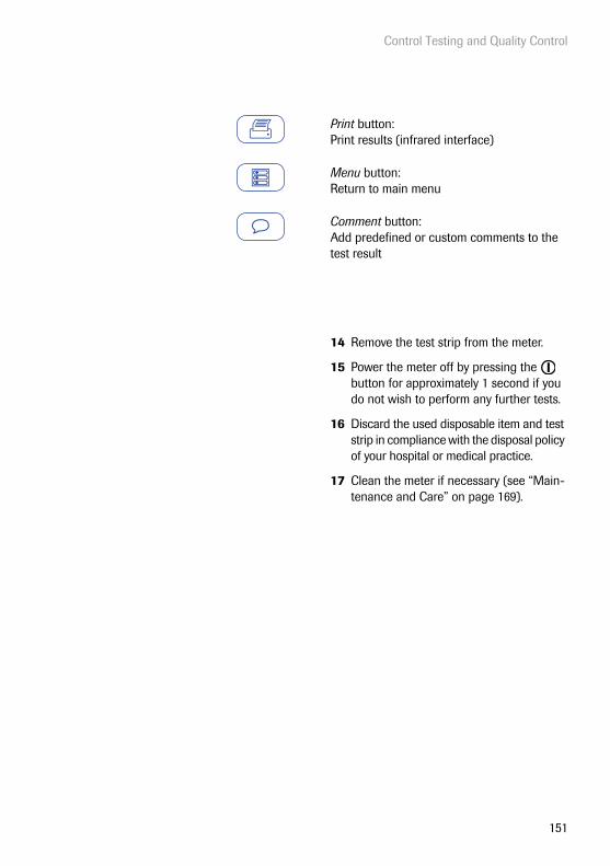
Control Testing and Quality Control
151
Print button: Print results (infrared interface)
Menu button: Return to main menu
Comment button: Add predefined or custom comments to the test result
14 Remove the test strip from the meter.
15 Power the meter off by pressing the button for approximately 1 second if you do not wish to perform any further tests.
16 Discard the used disposable item and test strip in compliance with the disposal policy of your hospital or medical practice.
17 Clean the meter if necessary (see “Main-tenance and Care” on page 169).

Control Testing and Quality Control
152
Instrument quality control (IQC)
The Roche CARDIAC IQC test serves as a performance check for the optical system of the cobas h 232 meter. The instrument determines the reflectance value of the signal and displays “Pass”, “Fail” or the percentage of remission depending on your settings.
“Pass” means that the optical system of the cobas h 232 meter is functioning properly. If “Fail” appears, the measured reflectance value is outside the confidence interval.
1 Prepare the required IQC test strips (shown here: Roche CARDIAC IQC high).
2 Make sure that the code chip supplied with these test strips is also at hand.

Control Testing and Quality Control
153
The first steps in this quality control test are identical to the procedure described before, see page 144. The following description therefore starts at the main menu.
3 Touch Control Test.
4 Touch in the QC Status screen to con-tinue with quality control test. The test strip icon prompts you now to insert a test strip.
5 Remove the test strip from its IQC test strip container.
6 Insert the test strip as described before, see page 145.
7 If you are using a new lot of IQC test strips and have not inserted the code chip yet, you must do so now. If you have used the test strips already, skip this step.
Main Menu
Control Test
Review Results
Setup
Patient TestQC!
09:15 am
04/19/2016
QC Test - QC Status
CK-MB
QC Status
MyoDDimer
- Pass
- Pass- Pass
Trop TproBNP
- Locked- Locked
04/19/2016
QC Test - Ins. Strip
Insert Strip
JONES, TOMOp:
04/19/2016
QC Test - Ins. ChipIQC
JONES, TOM
Par:
Op:
Insert Code Chip
04/19/2016
QC

Control Testing and Quality Control
154
The hourglass icon is displayed and the (internal) measurement begins.
The result of this IQC quality control test is displayed as Pass or Fail (default setting) or in the format selected in the QC result format setting.
There are three options for displaying an IQC test result:
• Pass/Fail
• Value
• Value & Pass/Fail
For details refer to “QC result format” on page 105 and “Settings summary” on page 47.
QC Test - MeasuringIQC IQC702Code:
JONES, TOM
Par:
Op:Level: 1
04/19/2016
QC Test - ResultIQC Code: IQC702
JONES, TOM
Par:
Op:
19/04/2016 10:17
Level: 1
04/19/2016
83 %(85 / 82 - 88 %)
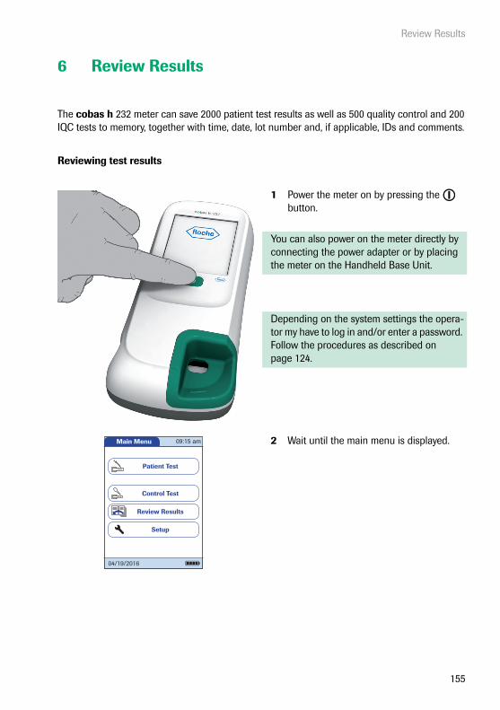
Review Results
155
6 Review Results
The cobas h 232 meter can save 2000 patient test results as well as 500 quality control and 200 IQC tests to memory, together with time, date, lot number and, if applicable, IDs and comments.
Reviewing test results
1 Power the meter on by pressing the button.
You can also power on the meter directly by connecting the power adapter or by placing the meter on the Handheld Base Unit.
Depending on the system settings the opera-tor my have to log in and/or enter a password. Follow the procedures as described on page 124.
2 Wait until the main menu is displayed.Main Menu
Control Test
Review Results
Setup
Patient Test
09:15 am
04/19/2016

Review Results
156
From the Main Menu you have access to all stored results, sorted by selectable criteria:
■ Patient History
■ All Results
■ QC Results (Quality Control)
■ IQC Results (Instrument Quality Control)
■ Maintenance History
3 Touch Review Results.
4 Select the function you want to perform in the memory.
The print button only appears if the printer function is activated. Otherwise it is not displayed.
Patient results only: The QR code button only appears if the QR code display function is activated. Otherwise it is not displayed.
Main Menu
Control Test
Review Results
Setup
Patient Test
09:15 am
04/19/2016
Review Results
All Results
QC Results
IQC Results
Patient History
Mainten. History
04/19/2016

Review Results
157
Patient history
This memory area contains a list of all patients, sorted by Patient ID. From here, you can call up results for any individual patient.
1 Touch or to display the entry of choice on the screen. If the arrow is just an outline , you have reached the beginning or end of the patient list.
2 Touch the patient name whose results you want to open.
3 Touch or to display the test result of choice on the screen.
4 Touch the test result you would like to view in detail.
Pat. History - Select ID
Scan
PID001GERTA123Anders, Gert
PID001CHAPLINC123Chaplin, Charlene
PID001BERNDH123Bernd, Hans
PID001FRENZENA12Frenzen, Alice
PID230ONEALJ1234ONeal, John
04/19/2016
Single Patient ResultsPat:
proBNP 620 pg/mL02/08/16 09:49
SCHULZ, MANFREDPID111SCHULZM457
DDimer High02/12/16 08:30
DDimer 1.3 µg/mL01/21/16 09:15
04/19/2016
Patient Result
62002/08/2016 09:49
pg/mL
proBNP PB1234
SCHULZ, MANFREDJONES, TOM
Par:Op:
Code:
PID111SCHULZM457Pat:
New Strip Lot
04/19/2016
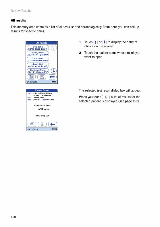
Review Results
158
All results
This memory area contains a list of all tests, sorted chronologically. From here, you can call up results for specific times.
1 Touch or to display the entry of choice on the screen.
2 Touch the patient name whose result you want to open.
The selected test result dialog box will appear.
When you touch , a list of results for the selected patient is displayed (see page 157).
All Results
Doe, John02/16 10:52 Trop-T
Zend, Nora02/16 09:40 DDimer
Smith, Adam02/16 10:11 proBNP
Smith, Bob02/15 11:40 Trop-T
Smithee, Aaron02/15 10:50 proBNP
04/19/2016
Patient Result
62002/08/2016 09:49
pg/mL
proBNP PB1234
SCHULZ, MANFREDJONES, TOM
Par:Op:
Code:
PID111SCHULZM457Pat:
New Strip Lot
04/19/2016
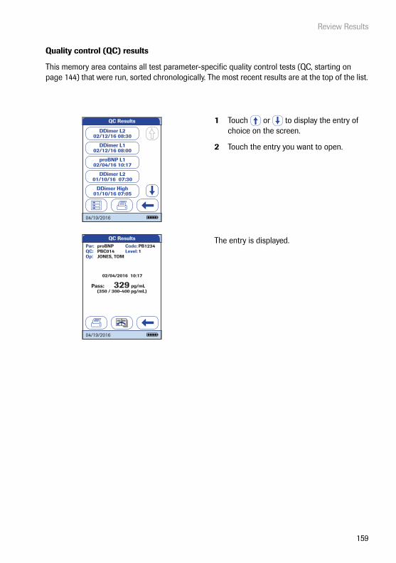
Review Results
159
Quality control (QC) results
This memory area contains all test parameter-specific quality control tests (QC, starting on page 144) that were run, sorted chronologically. The most recent results are at the top of the list.
1 Touch or to display the entry of choice on the screen.
2 Touch the entry you want to open.
The entry is displayed.
QC Results
DDimer L102/12/16 08:00
DDimer L202/12/16 08:30
proBNP L102/04/16 10:17
DDimer L201/10/16 07:30
DDimer High01/10/16 07:05
04/19/2016
QC Results
32902/04/2016 10:17
pg/mL(350 / 300-400 pg/mL)
Level:proBNP PB1234PBC014JONES, TOM
Par:
Op:
Code:QC: 1
Pass:
04/19/2016

Review Results
160
Instrument quality control (IQC) results
This memory area contains all instrument quality control tests (IQC, starting on page 152) that were run, sorted chronologically. The most recent results are at the top of the list.
1 Touch or to display the entry of choice on the screen.
2 Touch the entry you want to open.
The entry is displayed.
IQC Results
IQC Pass04/11/16 07:59
IQC Pass04/07/16 08:16
IQC Fail04/07/16 08:01
IQC Pass03/29/16 08:30
IQC Pass03/29/16 09:02
04/19/2016
QC Test - ResultIQC Code:
JONES, TOM
Par:
Op:
04/19/2016 07:59
Level: 1IQC702
83 %(85 / 82 - 88 %)
04/19/2016

Review Results
161
Maintenance history
Maintenance History actually is a list of comments. Whenever routine maintenance or service is done for the meter, this event can be stored in form of a comment. You may use the default preset comments in the meter or enter a custom comment.
1 Touch or to display the entry of choice on the screen.
Once saved, a maintenance comment can not be opened or edited. Maintenance History is (like test results) a view-only list. You can, however, add new entries:
2 Touch New.
3 Touch or to display the predefined comment of choice on the screen.
4 Touch the predefined comment you would like to add to the Maintenance His-tory or:
5 Touch Custom to enter your own text using the onscreen keypad.
6 Touch to save your comment.
Maintenance History
Meter Cleaned04/13/2016 08:00
Meter Cleaned04/05/2016 08:20
Meter Cleaned03/29/2016 09:00
New Battery Pack03/21/2016 08:30
Meter Cleaned03/14/2016 08:10
04/19/2016
New

Review Results
162
This page intentionally left blank.

Extended Functionalities
163
7 Extended Functionalities
Data handling
When used in conjunction either with WLAN (if the meter is equipped with WLAN) or with the (optional) Handheld Base Unit from Roche Diagnostics, the cobas h 232 meter can conveniently connect to a data management system (DMS). The main advantages of such a connection between meter and DMS may include:
■ Transferring patient lists, operator lists, and settings from the DMS to the meter. In this way the setup for daily work as well as general meter setup can be performed (for one or more meters) quickly and conveniently.
■ Transferring all stored test results with the corresponding Patient ID, Operator ID, and comments from the meter to the DMS. This transfer of data permits further evaluation or proper archiving according to your needs.
Through the DMS the system administrator (such as the POC coordinator) may specify what set-tings are to be applied to a set of meters within a site or unit (e.g., hospitals or wards). All meters assigned to a specific site and/or unit would consequently share the same settings. The different operator and patient lists (that match a site or unit) are then made available on their respective meters. Other settings such as QC Lockout and Operator Lockout may easily be set (once) and distributed to all meters.
Extended data handling functionality is dependent on the capabilities of the particular Data Management System (DMS) being used and may vary.
Preferably use incremental list updates instead of complete list updates, if your DMS supports this setup option.
The option of setting up an Operator Lockout is available only when operator lists are created on the DMS, stored in the meter, and Operator login is activated. For more details on Operator login see page 89, for details on Operator Lockout see page 97.
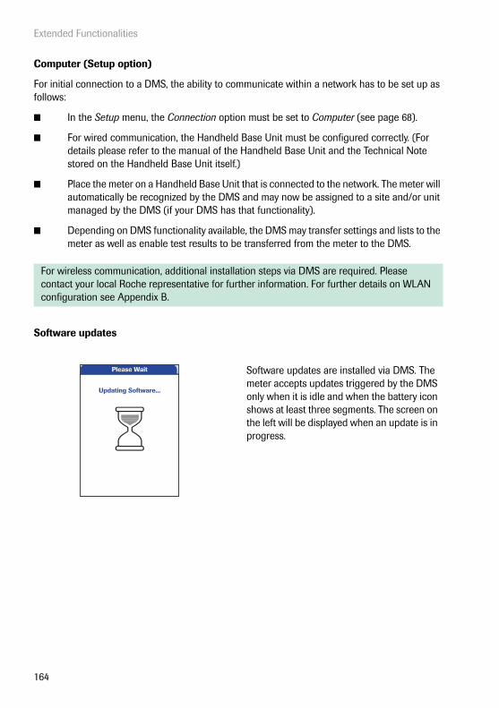
Extended Functionalities
164
Computer (Setup option)
For initial connection to a DMS, the ability to communicate within a network has to be set up as follows:
■ In the Setup menu, the Connection option must be set to Computer (see page 68).
■ For wired communication, the Handheld Base Unit must be configured correctly. (For details please refer to the manual of the Handheld Base Unit and the Technical Note stored on the Handheld Base Unit itself.)
■ Place the meter on a Handheld Base Unit that is connected to the network. The meter will automatically be recognized by the DMS and may now be assigned to a site and/or unit managed by the DMS (if your DMS has that functionality).
■ Depending on DMS functionality available, the DMS may transfer settings and lists to the meter as well as enable test results to be transferred from the meter to the DMS.
Software updates
For wireless communication, additional installation steps via DMS are required. Please contact your local Roche representative for further information. For further details on WLAN configuration see Appendix B.
Software updates are installed via DMS. The meter accepts updates triggered by the DMS only when it is idle and when the battery icon shows at least three segments. The screen on the left will be displayed when an update is in progress.
Please Wait
Updating Software...

Extended Functionalities
165
Operator lists
After powering the meter on, an Operator login may be configured. If no list is available, the options described on page 89 apply.
■ Operator is set to Optional or Required:The Operator can either log in via the onscreen keypad or a barcode scan. The use of the meter is not restricted to a predefined Operator group, so Operator IDs are entered via the onscreen keypad or read from the barcode and stored with test results for informational purposes only.
■ Operator is is set to Scan Only: The display of the meter's onscreen keypad is blocked. The Operator can only log in via a barcode scan as there is no onscreen keypad. The use of the meter is not restricted to a predefined Operator group, so Operator IDs are read from the barcode and stored with test results for informational purposes only.
Meters which are managed by a DMS may receive an Operator list.
■ Operator ID is set to List, a list is available and displayed on the login screen:The Operator selects the ID from the displayed list. If so configured by the Administrator, the Operator may also be required to enter a password to log in.
■ Operator ID is set to Hidden List:The Operator can login via a barcode scan or the onscreen keypad. If so configured by the Administrator, the Operator may also be required to enter a password to log in.
When working with operator lists: The use of the meter is restricted to the operators on this list.

Extended Functionalities
166
Patient lists
When starting a Patient Test, there will be the option of either selecting a Patient ID from a patient list, entering the Patient ID using the onscreen keypad or, if available, of scanning the barcode with the Patient ID. The Patient ID, if entered on the DMS, comes with an additional identification entry. Up to 20 characters can be used and assigned as a second confirmation (e.g., name, date of birth).
There are four possible configurations for a Patient ID input:
■ The Patient ID is set to Optional or Required, and there is no list available:A Patient ID can be entered manually via the onscreen keypad or read in via a barcode scan. The Patient ID is stored with the test result.
■ The Patient ID is set to No, but there is a list available:The list of Patient IDs is always shown when starting a test. You may now
– select a patient from the list;– scan a Patient ID using the barcode scanner;– create a new patient entry by touching New. Instead of an ID a consecutive number will
be assigned to this result.
■ The Patient ID is set to Optional or Required, and there is a list available:The list of Patient IDs is always shown when starting a measurement. You may now
– select a patient from the list;– scan a Patient ID using the barcode scanner;– create a new patient entry by touching New. You may either read the ID using the bar-
code scanner or enter a new ID via the onscreen keypad.
■ The Patient ID is set to Hidden List (only possible with a data management system), and there is a list available:An empty list is shown when starting a measurement. You may now
– scan a Patient ID using the barcode scanner;– create a new patient entry by touching New. You may either read the ID using the bar-
code scanner or enter a new ID via the onscreen keypad.
Extended Functionalities
167
Barcode scanner
Using a DMS, the barcode scanner may be configured to accept only selected barcode symbol-ogies. Furthermore, it is possible to define a barcode mask for Patient ID and Operator ID. With masks being defined, the meter checks a barcode after scanning and rejects it, if it does not match the mask. See “Example of barcode symbologies” on page 191 for further information.
Stored test results and comments
When performing a test, the test result will be stored along with additional information, including the Patient ID, Operator ID, the kind of test performed, and optional Comments. The meter comes with a default set of Comments that can be assigned to each test result. If you are working with a DMS, these comments can be replaced by the comments in the DMS. The new wording will then be available for selection from the Comments list in the meter.
When working with Patient lists, you have the following options:
■ A Patient ID does not have to be on the list to be scanned and used.
■ The meter displays a warning that the Patient ID scanned is not on the list.
■ The meter displays an error message that the ID was not found on the list of valid Patient IDs. You must enter a valid ID to proceed.
Up to 3 comments can be assigned to each result.
The Comment function may be configured to be either optional, required for test results which are out of range, or always required. If the user is required to enter/select a comment, com-pletely empty comments will not be accepted by the meter.

Extended Functionalities
168
The default preset comments in the meter are:
Patient and QC Result comments Maintenance comments
■ Symptomatic
■ Asymptomatic
■ Chest Pain
■ Dyspnea
■ Intermediate Zone
■ Doctor Notified
■ RN Notified
■ Under Medication
■ Will Repeat Test
■ No Action
■ New Strip Lot
■ New Strip/Kit Lot
■ New Lot Number
■ Lab Draw
■ Cleaned Meter
■ Switched QC Vial
■ Repeat Control Test
■ Acceptable Control
■ New Control Lot
■ Procedure Error
■ Meter Cleaned
■ Samp. App. Area Cl. (Sample Application Area Cleaned)
■ Test Strip Guide Cl. (Test Strip Guide Cleaned)
■ New Battery Pack
Maintenance and Care
169
8 Maintenance and Care
8.1 Conditions for storage and shipping
Storage
■ Store the system and test strips in the same environment in which they are used.
■ Do not store the meter in direct sunlight or under extreme temperature conditions.
■ Observe the limits for temperature and humidity when storing and using the meter (see Chapter 10).

Maintenance and Care
170
Shipping
■ If the meter is shipped or transported over long distances, always remove the battery pack from the meter. This eliminates the possibility of the battery pack overheating due to a short-circuit in the meter. It also prevents deep discharge and other damage to the bat-tery pack or meter.
■ Only ship undamaged battery packs. Damaged battery packs must be disposed of locally. See page 18 for the risks associated with damaged battery packs and disposal informa-tion.
■ Package the battery pack for shipping so that it cannot move around in the packaging. Also observe any other applicable national regulations.
■ When shipping via third parties (e.g., by air or parcel service), work with the carrier to check whether specific requirements need to be met in relation to the lithium-ion battery packs on the basis of national or international laws on hazardous goods and, where appli-cable, if special packaging and labeling requirements apply.
Observe the following safety information when shipping the meter and battery pack. Failure to do so may result in injury to persons or damage to the meter or battery pack.
For short distances - example between a facility’s sites - users may transport the battery packs (either installed in the meter or separately) by road without having to meet further require-ments.
Transport safety of the Handheld Battery Pack is proven to meet the requirements of each test in the UN Manual of Tests and Criteria, Part III, subsection 38.3.

Maintenance and Care
171
8.2 Cleaning and disinfecting the meter
Difference between cleaning and disinfecting
Cleaning is the physical removal of organic soiling (e.g., dirt, or other foreign material) from the meter surface.
Disinfecting is the removal of most, but not all, disease-causing and other types of micro-organisms (blood-borne pathogens) from the meter.
When should the meter be cleaned and disinfected?
■ Clean the meter to remove visible soil and organic material for safe handling and/or prior to disinfecting.
■ The exterior of the meter and the test strip guide and cover should be cleaned and disinfected following contamination due to mispipetting.
■ You can use the Cleaning Lockout function (see page 109) to ensure regular checks are performed.
What to clean and disinfect?
The following parts of the meter may be cleaned/disinfected:
■ The visible area of the test strip guide
■ The test strip guide cover
■ The meter housing (entire meter surface including display)
■ Observe the disinfection guidelines of your institution.
■ Use gloves. Gloves must be changed between patients.
NOTICE Follow the procedures below to clean/disinfect the meter. Failure to follow these procedures may cause malfunction of the meter.

Maintenance and Care
172
WARNING
Instrument damage due to moisture
Ensure that no liquid enters the meter. If moisture enters the meter, it may cause malfunction of the instrument.
■ Make sure the meter is powered off. Unplug the power adapter.
■ Do not spray anything onto the meter housing.
■ Do not spray into the test strip guide.
■ Do not immerse the meter in liquid.
■ Use only ordinary lint-free tissues.
■ Do not use cloths that are saturated. Squeeze off excess solution or blot on a dry paper towel to remove any excess solution before wiping the surface of the meter.

Maintenance and Care
173
Recommended cleaning/disinfecting agents
Before using a cleaning/disinfecting solution on the meter refer to the product labeling for required contact time for cleaning/disinfecting and to ensure that the active ingredients are acceptable for use. Prepare all solutions per the manufacturer’s product labeling.
Acceptable active ingredients are listed below.
Recommended cleaning agents
■ mild soapy water
Recommended disinfecting agents
■ Super Sani-Cloth Germicidal Disposable Wipes
Active Ingredient(s)
■ Premoistened disinfecting cloths (active ingredient 0.5% quaternary ammonium chlorides and up to 60% isopropanol).
NOTICE Do not use any other disinfectants/cleaning agents on the meter (housing or the test strip guide cover). Use of other disinfectants/cleaning agents could result in damage to the meter.
Maintenance and Care
174
Cleaning after contamination due to mispipetting
Observe the following precautions to prevent instrument damage
■ Do not move the meter to prevent liquids from creeping and penetrating the meter.
■ Dab away all visible blood (also on the test strip, but not in the application area).
■ Do not use the meter before the liquid/moisture has been completely removed. While it is drying, the meter must not be moved as this may soil the optical components.
For detailed cleaning instructions for the individual components of the meter, see the following pages. The instructions below describe only the sequence of steps to be taken in case of mispi-petting.
■ With the meter powered off, remove the test strip guide cover.
■ Remove and dispose of the test strip.
■ Clean the soiled parts of the meter with a moistened cotton swab/bud or tissue.
■ Disinfect the meter.
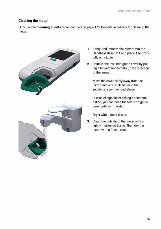
Maintenance and Care
175
Cleaning the meter
Only use the cleaning agents recommended on page 173. Procede as follows for cleaning the meter.
1 If required, remove the meter from the Handheld Base Unit and place it horizon-tally on a table.
2 Remove the test strip guide cover by pull-ing it forward horizontally (in the direction of the arrow).
Move the cover safely away from the meter and wipe it clean using the solutions recommended above.
In case of significant soiling or contami-nation, you can rinse the test strip guide cover with warm water.
Dry it with a fresh tissue.
3 Clean the outside of the meter with a lightly moistened tissue. Then dry the meter with a fresh tissue.

Maintenance and Care
176
4 Clean the easily accessible and visible pipetting field area of the test strip guide with moistened lint-free tissues.
WARNING
Protection against instrument damage
In order to avoid instrument damage, adhere to the following:
■ Clean only the visible area (large circle) of the test strip guide.
■ Do not insert any objects into the concealed areas of the test strip guide as this will damage the optical components of the meter.
■ Do not use objects to try to scratch off any dried contaminants in the test strip guide.
5 Clean the membrane (small circle) in the visible area at the end of the test strip guide with a moistened tissue.
6 Allow the inside of the test strip guide to dry for about 10 minutes.
7 Continue with disinfecting the meter.
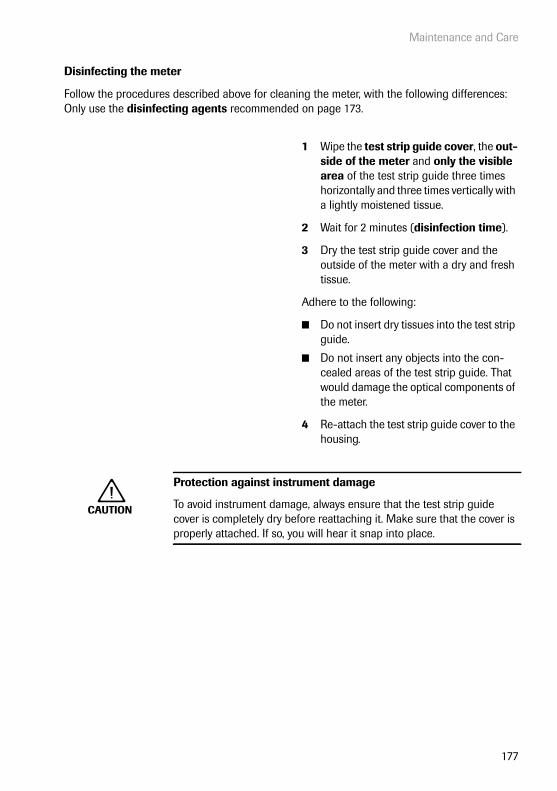
Maintenance and Care
177
Disinfecting the meter
Follow the procedures described above for cleaning the meter, with the following differences: Only use the disinfecting agents recommended on page 173.
1 Wipe the test strip guide cover, the out-side of the meter and only the visible area of the test strip guide three times horizontally and three times vertically with a lightly moistened tissue.
2 Wait for 2 minutes (disinfection time).
3 Dry the test strip guide cover and the outside of the meter with a dry and fresh tissue.
Adhere to the following:
■ Do not insert dry tissues into the test strip guide.
■ Do not insert any objects into the con-cealed areas of the test strip guide. That would damage the optical components of the meter.
4 Re-attach the test strip guide cover to the housing.
CAUTION
Protection against instrument damage
To avoid instrument damage, always ensure that the test strip guide cover is completely dry before reattaching it. Make sure that the cover is properly attached. If so, you will hear it snap into place.

Maintenance and Care
178
This page intentionally left blank.

Troubleshooting
179
9 Troubleshooting
The cobas h 232 meter continually checks its systems for unexpected and unwanted conditions. These may arise for technical reasons (defective components or consumables, environmental factors) or due to handling and procedure errors.
Depending on the circumstances, a message may appear on the display of the meter. These messages are marked with an icon, either for a status message, or for an error message. All messages displayed by the system are accompanied by a description of the error and a pos-sible solution.
Take the action suggested on screen to resolve the problem. If the error disappears, you may continue using the meter as desired. If the problem persists, contact Roche (see page 205).
The two different message types are illustrated below:
Display/symptom Description
I-001: Battery Low
Status message
Touch to proceed with the next step.
E-101: Patient ID Required
Error message
Touch to exit this message. Perform the suggested step(s) to solve the problem.
Battery Low
I-001The battery is getting low. Recharge battery pack as soon as possible.
Patient ID Required
E-101A patient ID is required. Enter a valid patient ID.

Troubleshooting
180
Errors and unusual behavior without error messages
Some conditions may arise that have no associated error or status message.
Display/symptom Description
No message or unusual behavior
Meter display does not power on
■ Wait 10 seconds and try powering on the unit again.
■ Check that the meter has power.
• If you are using the external power adapter, is it connected properly to the meter?Or:
• Place the meter in the Handheld Base Unit.Or:
• Is the Handheld Battery Pack properly installed in the meter?
Meter displays an unexpected result
Refer to the package insert for the test strips.
Automatic shutdown
The meter powers off after a configurable time with-out activity (e.g., pressing a key, touching the screen) to conserve energy.
■ Press the On/Off button to reactivate the meter/screen.

Troubleshooting
181
Communication Problems with the Data Management System via RF
The cobas h 232 meter is unable to communicate with the Data Manage-ment System.
■ Check WLAN functionality on the meter (see the Wireless Setup screens in section “Diagnostics” starting on page 80).
■ Dock the RF enabled meter into a hard-wired base unit to transfer the data.
■ Reset the meter.
■ If the error persists, contact your Roche representative.
Display/symptom Description

Troubleshooting
182
Meter reset
A hard reset should only be performed if all other remedies have failed.
1 Place the meter on a level surface.
2 Press the button for at least 12 seconds.
■ The meter powers off and on again.
■ The Roche logo is displayed. If the Roche logo does not appear within 60 seconds, place the meter in the Hand-held Base Unit for a minimum of 15 minutes to recharge the battery pack.
■ The meter performs a system check.
■ The screens for entering the date and the time appear.
3 Enter the date and time. After you have entered the correct information, confirm each screen with .
■ Unless all lockouts are disabled (see chapter 3.4), the meter will now be in QC Lockout due to the manually entered date/time.
4 Synchronize the meter’s date/time with the date/time of your facility via the Hand-held Base Unit or, if working wirelessly, wait at least ten minutes for the next WLAN synchronization before performing any further tests.
Even if your configuration does not require it, we recommend always performing a QC test after a meter reset.
Self-Check
Performing self-checks...
04/19/2016
SW Version: v04.00.00
09:15 am
Self-Check
Self-checks complete.
04/19/2016
SW Version: v04.00.00
09:15 am
Set Date
Month: 1
Day: 1
Year: 2016
04/19/2016
Minutes: 49
Hour: 3Set Time
04/19/2016
AM PM
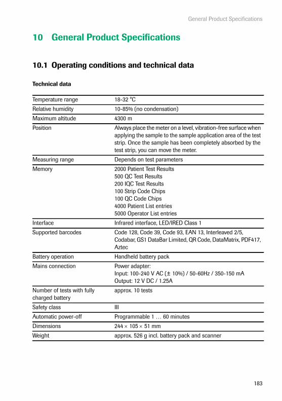
General Product Specifications
183
10 General Product Specifications
10.1 Operating conditions and technical data
Technical data
Temperature range 18-32 °C
Relative humidity 10-85% (no condensation)
Maximum altitude 4300 m
Position Always place the meter on a level, vibration-free surface when applying the sample to the sample application area of the test strip. Once the sample has been completely absorbed by the test strip, you can move the meter.
Measuring range Depends on test parameters
Memory 2000 Patient Test Results500 QC Test Results200 IQC Test Results100 Strip Code Chips100 QC Code Chips4000 Patient List entries5000 Operator List entries
Interface Infrared interface, LED/IRED Class 1
Supported barcodes Code 128, Code 39, Code 93, EAN 13, Interleaved 2/5, Codabar, GS1 DataBar Limited, QR Code, DataMatrix, PDF417, Aztec
Battery operation Handheld battery pack
Mains connection Power adapter: Input: 100-240 V AC (± 10%) / 50-60Hz / 350-150 mAOutput: 12 V DC / 1.25A
Number of tests with fully charged battery
approx. 10 tests
Safety class III
Automatic power-off Programmable 1 … 60 minutes
Dimensions 244 105 51 mm
Weight approx. 526 g incl. battery pack and scanner

General Product Specifications
184
Sample material
Storage and transport conditions
Sample type Heparinized venous whole blood
Sample size 150 μL
Interactions Refer to test strip package insert
Temperature range –25 °C to +70 °C
Relative humidity 10 to 85% (no condensation)

General Product Specifications
185
10.2 Further information
Ordering information
Please contact your specialist supplier.
Item Description REFRoche CARDIAC POC Troponin T 10 tests for quantitative detection of cardiac
Troponin T07007302190
Roche CARDIAC POC Troponin T Control
Control set for use with Roche CARDIAC POC Troponin T (control set for 2 x 6 quality control checks, level 2, and code chip)
07089643190
Roche CARDIAC POC Troponin T 2 Level Control
Control set for use with Roche CARDIAC POC Troponin T (control set for 2 x 6 quality control checks, level 1/2, and code chip)
07831005190
Roche CARDIAC POC Troponin T Control (Germany only)
Control set for use with Roche CARDIAC POC Troponin T (control set for 2 x 6 quality control checks, level 2, and code chip)
07912218190
Roche CARDIAC T Quantitative (Troponin T)
10 tests for quantitative detection of cardiac Troponin T
04877772190
Roche CARDIAC Control Troponin T Control set for use with Roche CARDIAC T Quantitative (control set for 2 x 6 quality control checks, level 1/2, and code chip)
04890515190
Roche CARDIAC Control Troponin T (Germany only)
Control set for use with Roche CARDIAC T Quantitative (control set for 2 x 6 quality control checks, level 2, and code chip)
05453879190
Roche CARDIAC M 20 tests for quantitative detection of myoglobin 04877799190
Roche CARDIAC Control Myoglobin Control set for use with Roche CARDIAC M (control set for 2 x 6 quality control checks, level 1/2, and code chip)
04890469190
Roche CARDIAC D-Dimer 10 tests for quantitative detection of D-Dimer 04877802190
Roche CARDIAC Control D-Dimer Control set for use with Roche CARDIAC D-Dimer (control set for 2 x 6 quality control checks, level 1/2, and code chip)
04890523190
Roche CARDIAC proBNP+ 10 tests for quantitative detection of NT-proBNP (measuring range 60 - 9,000 pg/mL for meter software version ≥ 01.04.01)
05533643190
Roche CARDIAC Control proBNP Control set for use with Roche CARDIAC proBNP+(control set for 2 x 6 quality control checks, level 1/2, and code chip)
04890493190
Roche CARDIAC CK-MB 10 tests for quantitative detection of CK-MB 04877900190
Roche CARDIAC Control CK-MB Control set for use with Roche CARDIAC CK-MB (control set for 2 x 6 quality control checks, level 1/2, and code chip)
04890426190

General Product Specifications
186
Note: Not all items are available in all countries.
Roche CARDIAC IQC Set of two re-usable control strips (high/low) including code chip. Needed for checking the performance of the meter’s optical system
04880668190
Roche CARDIAC pipettes 20 disposable syringe pipettes (150 μL) for blood application
11622889190
Universal battery pack Rechargeable battery pack for cobas h 232 meter
06869904001
Test strip guide cover 07751109001
Battery compartment cover 07751125001
Power adapter 07006098001
Handheld Base Unit 04805658001
cobas h 232 meter Version without scanner/without WLAN 04901126190
cobas h 232 meter Version with scanner/with WLAN 04901142190
cobas h 232 Operator’s Manual Printed manual (English) 07469101001
cobas h 232 Operator’s Manual Printed manual (German) 07532920001
cobas h 232 Manual CD Contains Operator’s Manuals and Quick Refer-ence Guides in all available languages (PDF)
07469314001
Printer cobas h 232 (CMP-10) ROW
for most North American, Latin American and Asian countries
05404495001
Printer cobas h 232 (CMP-10) EMEA
for most European, Middle East and African countries
05404517001
Printer cobas h 232 (CMP-10) JAP
for Japan 05404509001
Normal thermal paper roll 5 rolls per package, 50 mm diameter 03666751001
Thermal paper roll (self-adhesive) 10 rolls per package, 50 mm diameter 05412951001
Item Description REF

Warranty
187
Product limitations
Please read the information in the package insert supplied with the test strips for detailed product data and limitations.
Information about software licenses
This product incorporates software modules developed under open source licenses. The source code of this software can be requested on a standard data exchange medium from the manufac-turer at the following address:
Roche Diagnostics GmbHSandhofer Str. 11668305 Mannheim, Germany
The General Public License (GPL) licensing conditions are available (in English only for legal rea-sons) as a text file (file name “License_txt.PDF”) on the CD supplied with this manual. The com-plete license agreements are also stored as a text file (file name “license.txt”) on the Handheld Base Unit. You can access this file by connecting the base unit to a PC with the USB cable. For detailed instructions on how to do this, see the Operator's Manual of the Handheld Base Unit.
Everyone is permitted to copy and distribute verbatim copies of this license document, but changing it is not allowed.
Repairs
Please note that repairs and other modifications to the meter may only be performed by persons authorized by Roche.
11 Warranty
The statutory guarantee provisions on rights in consumer goods sales in the country of purchase shall apply.

Warranty
188
This page intentionally left blank.

189
A Appendix
A.1 Working with barcodes
To reduce the probability of the barcode being misread, it is strongly recommended that you use the configuration options for patient and/or operator ID validation as applicable to your specific workflow. These options are:
■ check ID against list or
■ check ID for length1
■ check if the scanned bar code type is allowed and activated in the DMS
■ use barcodes with check digits
In combination with the above options or as a single measure, use an appropriate barcode mask if this is compatible with the structure of your barcode content.
Always make sure that the entire barcode is covered by the green light frame when scanning.
WARNING
Risk of barcode read errors
If a barcode is read incorrectly, this may lead to patient misidentification and therefore to inappropriate therapy decisions.
When creating patient or operator barcodes, always adhere to the applicable international IEC/ISO standards for the respective barcode symbology. In particular, ensure that barcode size and print quality (as defined in ISO/IEC 15416 and 15415) are adequate. Inadequate print size and/or quality may lead to erroneous decoding. In addition every user must carry out a plausibility check on all data scanned into and displayed by the instrument.
1. If no operator/patient list can be used, it is recommended that you at least set a minimum length for the respective ID, even if your facility uses IDs of varying length.

190
A.2 Operator and patient ID barcode masks
Barcode mask character Definition
A-Z, 0-9 If not preceded by the Caret (“^”), the scan data character must be the same as the mask character. This character is not saved as part of the ID. If the characters are not the same, the scan data is not a valid ID.
Dollar (“$”) The scan data character in this position is kept as part of the ID.
Asterisk (“*“) The scan data character in this position is not kept as part of the ID.
Tilde (“~”) The scan data character in this position must be a number, 0-9, and it is not kept as part of the ID. If the scan data character is not a number, the scan data is not a valid ID.
Plus (“+”) The scan data character in this position must be an alpha character, A – Z, and it is not kept as part of the ID. If the scan data character is not an alpha character, the scan data is not a valid ID.
Caret (“^”) This mask character denotes that the scan data character must be equal to the next character in the barcode mask after the “^”, and that the scan data character is kept as part of the ID. If the scan data character is not equal to the mask character following the “^”, the barcode reading is invalid as an ID.
The allowed maximum length of a barcode mask is 300 characters for 1D and 2D barcodes.

191
A.3 Example of barcode symbologies
The barcode samples shown here are for illustration purposes only. If printed out, they can be used to check the barcode scanner. However, they are not meant to be used as a reference for size or resolution of real patient or operator ID barcodes. When creating patient or operator bar-codes always refer to the relevant standards ISO/IEC 15416 and 15415 for size and resolution requirements and to the specification listed below.
WARNING
Avoidance of incorrect EAN 13 and Interleaved 2/5 barcode readings
EAN 13 and Interleaved 2/5 barcodes, although widely used, are not recommended for patient/operator barcodes.
If an EAN 13 or Interleaved 2/5 barcode is read incorrectly, this may lead to patient misidentification and therefore to inappropriate therapy decisions. If used nonetheless:
■ make sure that the very highest quality standards of barcode creation and reproduction are applied
■ for EAN13: do not use the start sequences 978 (ISBN) and 979 (ISMN) as they will be ignored as a part of any ID code
Recommended Specification Remarks
Print resolution 300 dpi preferred200 dpi minimum
At 200 dpi issues with the wide-to-narrow ratio may exist.
Reflective contrast 70% or greater Matte finish is preferred over gloss finish.
Symbol grade Grade C or aboveGrade B is preferred
Symbol grades are A-F based on analysis of several quality elements.
Depending on quality grade parameters for a specific bar code, grade C may not be sufficient when motion, reflection, or poor lighting occur.
Module width (minimum)
0.16 mm (linear barcodes)0.20 mm (2D barcodes)

192
Codabar Code 39
Code 93 Code 128
EAN 13 Interleaved 2/5 without checksum
PDF417 RSS (GS1 DataBar Limited)
Aztec DataMatrix
QR Code
Roche Diagnostics
Roche Diagnostics Roche Diagnostics
Roche Diagnostics

193
A.4 Supported characters in 2D barcodes
The 2D barcode scanner is able to read characters from the following unicode ranges:
■ Basic Latin (0021-007E)
■ Latin-1 Supplement (00A1-00FF)
■ Latin Extended-A (0100-017F)
The 2D barcode scanner does not support Asian characters.

194
This page intentionally left blank.

195
B Appendix
B.1 Option: Wireless network (WLAN)
Preliminary note
Appendix B has been developed to explain the wireless communication principles of the cobas h 232 system1 and to help your facility’s information technology/management team(s) in effectively deploying the cobas h 232 system on your wireless network.
Whether your meter is equipped with WLAN functionality or not depends on the system configuration that you purchased.
For information on WLAN registration see the addendum “WLAN registration information, Addendum to the Operator’s Manual for cobas h 232” which can be downloaded from the “Point of Care testing” area at www.cobas.com.
Background
The cobas h 232 meter can only be configured through a data management system to commu-nicate wirelessly. The data management system is also used to set-up and configure the meter to connect to one hospital specific Wireless Local Area Network (WLAN2). WLANs use electro-magnetic waves in the 2.4 and/or 5.0 GHz frequency range to wirelessly transmit data3. The cobas h 232 system adheres to IEEE Standard 802.11g (2.4 GHz range)4. The system is back-wards compatible to 802.11b. During wireless communication to an Access Point (AP), the cobas h 232 meter recognizes the existent AP WLAN protocol configuration (802.11b or 802.11g) and automatically transmits data using the appropriate communication protocol5.
1. The cobas h 232 system is certified by the Wi-Fi Alliance.2. WLAN is also commonly referred to as wireless LAN or Wi-Fi.3. For the wireless functionality to work properly, the wireless module must first be configured by your
system administrator.4. While the cobas h 232 system adheres to the 802.11g standard, it uses only channels 1-11. Channels
12-14 are not used by the system.5. WLANs are organized in cells. A typical WLAN cell consists of Access Point(s) that are connected to
the (wired) Local Area Network and one or more clients, e.g., cobas h 232 meters along with other clients such as portable computers.

196
The loss of signal or access to bandwidth of one particular client may vary depending on one or more of the following situations: the type and number of other clients, the performance of the Access Point, the presence of electromagnetic disturbances, and other potential interfering factors, e.g., concrete walls.
The cobas h 232 meter uses a burst-like communication protocol that will only consume band-width if there is actually data to be transferred. Compared to other applications, such as Voice over Internet Protocol (VoIP) or multi-media applications, the meter’s bandwidth consumption is minimal. If the WLAN that the cobas h 232 meter seeks to connect to is degraded, the meter design minimizes the impact on functionality.
Technical implementation
Prior to connecting any wireless device to a wireless network, it is recommended that a WLAN site survey be performed. The goal of a WLAN site survey is to ensure that Access Points will pro-vide enough coverage and performance to support any new radio frequency (RF) application or device. The survey will also detail RF signals, including all existing WLANs along with any com-peting RF signals and interferences (building structure related and other wireless equipment / devices).
As part of an RF implementation of the cobas h 232 system, it is recommended that at minimum one base unit be hard wired per floor. A networked base unit provides redundancy if a wireless network malfunctions or loses service. If the cobas h 232 meter with RF is used in an area with low signal or interferences, it is recommended to install a connected base unit for redundancy. The redundancy of the connected base unit allows immediate transmission of patient results when the meter is docked.

197
The current RF system consists of an antenna and a WLAN system-on-chip (SoC) along with other components. The WLAN system-on-chip is the core of the WLAN system. The RF system used in the cobas h 232 meter specifically adheres to the following specifications:
■ Its WLAN system-on-chip supports IEEE 802.11b and 802.11g. It works seamlessly together with other Wi-Fi certified transceivers. It also implements the Wi-Fi Protected Access (WPA™ - Enterprise and WPA™ - Personal), Wi-Fi Protected Access 2 (WPA2™ - Enterprise and WPA2™ - Personal), and Wired Equivalent Privacy (WEP) secu-rity mechanisms with Temporal Key Integrity Protocol (TKIP) and Advanced Encryption Standard (AES). In addition, the system supports the extensible authentication protocol (EAP) with EAP-TLS, EAP-TTLS/MSCHAPv2 and PEAPv0/EAP-MSCHAPv2. The cobas h 232 meter interoperability Wi-Fi certificate can be accessed at http://certifications.wi-fi.org/search_products.php. Further information including a glossary of terms, frequently asked questions, and other topics related to Wi-Fi technology can be found on the Wi-Fi Alliance site (http://www.wi-fi.org/).
■ The used channels in the 2.4 GHz-band are channels 1-11. (Channels 12-14 are not used by the cobas h 232 meter.)
■ RF output power is approximately 15 dBm at a data rate of 54 MBPS.

198
RF specific functionalities and effective performance claims
The cobas h 232 system offers the option of wireless network connectivity (WLAN/Wi-Fi). If you purchase a system with this option, the WLAN function is enabled during production.
This module can only be configured by a data management system (DMS), which activates the meter’s wireless communication and data transfer capabilities. Wireless connectivity can help to ensure that updates to information in the DMS are sent immediately to all networked meters. Communication takes place when the meter is idle, but will be interrupted during the perfor-mance of a test.
Meters with an integrated and activated wireless option use the base unit for recharging and/or as a redundant communication option to exchange data with the DMS.
The meter also has to be docked if the hospital changes security protocols. When this change occurs, it may lock out all meters until docked and reconfigured with the new protocol.
As described above, the cobas h 232 meter supports the 802.11g standard. This translates into the following RF specific performance claims:
■ The cobas h 232 meter is capable of transferring to a suitable DMS, via WLAN, a data set of up to 1000 result records, 100 reagent records, and 500 operator ID records in less than 15 minutes, when operated in a typical WLAN environment (correct WLAN admin-istration, typical population of other clients present, any of the supported security models enabled).
■ A cobas h 232 meter with wireless connectivity enabled will communicate results after every test or when the meter is idle; it will automatically attempt to communicate with the DMS every 10 minutes. In line with the industry communication standard POCT1-A, the DMS must acknowledge the meter’s request for connection and actively query for the result. Only upon receipt of this DMS query, the meter will send the result. Hence the effective time for transmitting results depends on infrastructure, DMS workload, etc. Once the DMS sends a query, however, the meter will respond within a few seconds.
199
A typical range for direct connection between the cobas h 232 meter and the access point (air, direct view, low disturbances) is up to 15 to 20 meters (49 to 66 feet). The actual range depends on the positioning of the access point’s antennas and other topological properties of the space between WLAN device and AP. Additionally, dynamic control of the transmitting power of the access point may reduce the maximum distance between WLAN device and AP within which communication can be guaranteed.
The cobas h 232 system is designed such that it coexists with other wirelessly communicating devices. The cobas h 232 system does NOT include any real-time or even time critical wireless functionality. It communicates exclusively single, digital data fields. It does NOT communicate continuous waveform data.
Note: A degraded Quality of Service (QoS) of the WLAN communication will not impact the functionality of the meter but may delay the communication of results to the DMS. Users should be aware that real-time communication of test result readings cannot be guaran-teed by the cobas h 232 meter.

200
This page intentionally left blank.

201
C Supplement for Observed Test Sequence
Observed Test Sequence (OTS)
The Observed Test Sequence (OTS) function allows an observer (supervisor) to assess and record an operator’s performance (e.g., for recertification purposes). The observer monitors an operator during a test to check that the test is being performed according to the recommended proce-dures. He/she then evaluates the performance and passes or fails the operator. This assessment is saved together with the test result and any desired comments.
Observed Test Sequence options can only be configured using a DMS. The availability of electronic configuration options will thus vary according to the data management software utilized by your institution. Consult your system administrator.

202
Using the OTS function
A request for an Observed Test Sequence comes from the DMS. The presence of the icon on the Patient Test button indicates a pending OTS request.
Observer:
1 Touch Patient Test.
In the Pat. Test -OTS menu, the Patient Test button is grayed out (disabled) until the observer has logged in.
2 Touch Observer Login.
3 Wait until the observer list is displayed.
4 Select your observer ID by touching the corresponding button, or scan your operator ID (which is also your observer ID in this case)..
Only operators with OTS observer rights are listed in the Observer Login list.
5 Enter the (optional) password.
6 After you enter your password, touch to log in. The Pat. Test - OTS menu is dis-played again. The Patient Test button is now active.
7 Hand the meter to the operator who can now perform the patient test under supervision.
Main Menu
Control Test
Review Results
Setup
Patient Test
Logout
09:15 am
04/19/2015
Pat. Test - OTS
Observer Login
Patient Test
OTS enabled
04/19/2016
Observer
Ann Casey
Alan Smithee
Scan
04/19/2016
Pat. Test - OTS
Observer Login
Patient Test
OTS enabled
04/19/2016

203
Operator:
1 Touch Patient Test.
Perform the patient test as usual. Once the test is completed, the observer has to com-plete the next steps.
2 Hand the meter back to the observer.
Observer:
3 Touch to log in again.
4 After you enter your password, touch to proceed with the assessment.
5 Assess the operator’s performance by touching Pass or Fail.
6 Assess the test result by touching Accept or Reject.
7 Touch to add a comment.
8 Touch to return to the Pat. Test - OTS screen.
The OTS information is saved together with the test result.
Pat. Test - OTS
Observer Login
Patient Test
OTS enabled
04/19/2016
Observer Login
I-010Observer Alan Smithee, please log in to proceed. Otherwise the OTS test will not be complete.
ObserverOTS passed:
Pass Fail
04/19/2016
Measurement Result OK?
Reject Accept
Comment:
Remove Strip
Remove Strip
04/19/2016

204
This page intentionally left blank.

205
D Contact Roche
For all questions about the cobas h 232 system that are not answered in this manual, contact your Roche representative. If you do not already have contact details, visit our website at www.roche.com. Click on “Menu”, then select “Roche in your country” in the “Our business” area to find the appropriate local office contact information.

206
This page intentionally left blank.

207
Index
AAdministrator ..................................................... 83Administrator ID
Change ......................................................... 87Disable ......................................................... 88Set up .................................................... 83–86
Application area ............................................... 29Apply sample ................................................... 133
Opening (meter) ....................................... 25Auto off ................................................................ 62
BBarcode ................................................... 124, 129
Masks ......................................................... 190Symbologies ............................................. 192
Barcode (test strip) .......................................... 29Barcode reader ................................................. 29Barcode scanner .............................................. 25Basics (setup) ............................................. 49–63Battery pack ......................................... 25, 27, 35
Installing or replacing ...................... 36–40
CCleaning .................................................. 171–176
After mispipetting .................................. 174Housing - outside .................................. 175Test strip guide ....................................... 176
Cleaning lockout ............................................ 109cobas h 232
Contents of the pack .............................. 13Introduction ................................................ 11Operating conditions ............................ 183Overview of meter elements ......... 24–26Test principle ............................................. 13
cobas IT 1000 .................................................... 11Code chip ......................................... 29, 118–119
Opening ....................................................... 26Comment (custom) ....................................... 138Comment result .............................................. 138
Computer ............................................ 64–68, 164Connection ...................................................64–70Contact Roche ................................................ 205Contents of the pack .......................................13Contrast .........................................................49–50Control material .............................................. 143Custom range ........................................106, 107
DData handling .............................................64–81Data Management System (DMS) ....................................73, 83, 92, 93, 163Data transfer ................................................... 163Date ................................................................53–54Diagnostics ..................................................80–81Display format .............................................57–58Disposal ...................................................... 17, 117
EError messages ............................................... 179
HHandheld Base Unit .........................................36
IIcons: see SymbolsID setup .........................................................82–95
Overview ......................................................82Infections (safety instructions) ................. 117Infrared interface .................................... 26, 163IQC lockout ...................................................... 104
LLanguage ......................................................51–52Lockout ....................................................... 96–111
Cleaning lockout .................................... 109IQC lockout .............................................. 104New lot lockout ...................................... 102Operator lockout ................................97–99QC lockout ............................................... 103

208
MMeter
Reset ...........................................................182Meter setup
Administrator ID ................................ 83–86Auto off ........................................................ 62Basics .................................................... 49–63Cleaning lockout ....................................109Computer ............................................. 64–68Contrast ................................................ 49–50Data handling ..................................... 64–81Date ........................................................ 53–54Diagnostics .......................................... 80–81Display format .................................... 57–58ID setup ................................................ 82–95IQC lockout ...............................................104Language ............................................. 51–52Lockout ...............................................96–111New lot lockout .......................................102Operator ID .......................................... 89–92Operator lockout ............................... 97–99Optional screens ........................... 112–114Overview ............................................... 44–48Patient ID .............................................. 93–95Printer .................................................... 69–70QC lockout ................................................103QC result format ........................... 105, 106QR Code ............................................... 65–67Reset test parameters ...........................108Result confirmation ...............................114Result display mode ......................... 78–79Result login ...............................................113Result memory ................................... 71–74Result unit ............................................ 75–77Sound .................................................... 59–61Start info ....................................................113STAT test ...................................................110Time ........................................................ 55–56
NNew lot lockout .............................................. 102
OObserved Test Sequence (OTS) ......201–203On/Off button .....................................................25Operating conditions .................................... 183Operating the meter ................................ 35–41Operator ID .............................. 89–92, 123–125Operator list ............................................124, 165Operator lockout ....................................... 97–99Optional screens ...................................112–114Ordering information .................................... 185Overview of meter elements ................. 24–26
PPatient ID .................................. 93–95, 127–129Patient list ...................................... 127–129, 166Power adapter
Connection .......................................... 26, 30Power supply ......................................................27
Contacts (Handheld Base Unit) ..........26Powering on the meter ............. 122, 144, 155Printer ............................................................ 69–70Product specifications ................................. 183
QQC lockout ....................................................... 103QC result format ....................................105, 106Quality control ........................................141–154
Control material ...................................... 143IQC (instrument-specific) ..........152–154Pass/Fail .................................................... 154Preparation ............................................... 143QC (test parameter-specific) ....144–151

209
RReset ................................................................... 182Reset test parameters .................................. 108Result confirmation ............................. 114, 137Result deletion (automatic) .......................... 74Result display mode ................................. 78–79Result login ............................................ 113, 136Result memory ..................................71–74, 155Result unit .................................................... 75–77Review results ....................................... 155–168
All results .................................................. 158Data transfer ............................................ 163IQC (instrument quality control) ....... 160Maintenance ............................................ 161Patient history .......................................... 157QC (quality control) ............................... 159
RF (radio frequency) ..............................22, 196
SSafety
Protection against infection ................. 15User qualification ..................................... 15
Sample material .................................... 117, 184Scan (button) ......................................... 124, 129Self-check (powering on the meter) ...... 122Software license ............................................. 187Sound ............................................................ 59–61Specifications .................................................. 183Start info ............................................................ 113STAT test ............................................................. 96
Configure .................................................. 110Perform ...................................................... 140
Storage ............................................................... 169Storage and transport conditions ............ 184Symbols
Code chip ........................................ 131, 146Error messages ....................................... 179Hourglass ........................................ 134, 149Meter ...............................................................5Packaging ......................................................5Pipette .............................................. 132, 147Screen ................................................... 31–33Thermometer ................................. 131, 147
TTest ............................................................115–140
Performing .......................................126–140Preparing .........................................117–125Sample material ..................................... 117
Test area ..............................................................29Test principle ......................................................13Test steps (overview) ................................... 120Test strip
Inserting ...........................................130, 145Lot ............................................................... 100
Test strip guide ..................................................26Test strip guide cover .....................................25Time ................................................................55–56Touchscreen ................................................25, 43Troubleshooting ............................................. 179
WWi-Fi ......................................................................22WLAN ................................................................. 195

210
This page intentionally left blank.


0 78
8659
4001
(02
) 20
17-1
1 EN
-CA
N
ROCHE CARDIAC, COBAS, COBAS H and IQC are trademarks of Roche.
Roche Diagnostics GmbHSandhofer Strasse 11668305 Mannheim, Germany
www.roche.com
www.cobas.com