CNS and Dme at BMA, Ranchi
22
PRESENTATION ON CNS & DME AT AIRPORT AUTHORITY OF INDIA, RANCHI SUBMITTED BY:- DIMPY SONOWAL(JV-B/10/1715) KUNUR K BAXLA(JV-B/10/1761) KOTHARE NITISHA(JV-B/10/1660) NIDHI P TIGGA(JV-B/10/1702) NINGAM WANGSA(JV-B/10/1716)
-
Upload
nitigga92 -
Category
Engineering
-
view
62 -
download
4
Transcript of CNS and Dme at BMA, Ranchi

PRESENTATION ONCNS & DME
ATAIRPORT AUTHORITY OF INDIA, RANCHI
SUBMITTED BY:-
DIMPY SONOWAL(JV-B/10/1715)KUNUR K BAXLA(JV-B/10/1761)KOTHARE NITISHA(JV-B/10/1660)NIDHI P TIGGA(JV-B/10/1702)NINGAM WANGSA(JV-B/10/1716)

INTRODUCTION TO BMA WHAT IS CNS? CNS FACILITIES VHF COMMUNICATION RADIO WAVES CLASSIFICATION (USEN IN CNS EQUIPMENTS) AMSS ILS DME DME USING ULTRASONIC WAVES(PROJECT)

The Airport is located at Ranchi, Jharkhand. The airport is named as Birsa Munda who was a tribal leader during the British Raj making him an important figure in Indian independence movement .
Birsa Munda Airport is a public domestic airport serving the city of Ranchi, Jharkhand, India and is managed by the Airports Authority of India.
ICAO (International civil aviation organization)is specialized authority. It was formed in 4th april 1947. Its headquarter is located in Quartier Internationale of Montreal, Quebec, Canada.

Communication, Navigation and Surveillance are three main functions(domains) which constitute the foundation of Air Traffic Management(ATM) infrastructure.
Communication: Communication is the exchange of voice and data information between the pilot and air traffic controller of flight information centres.
Navigation: Navigation element of CNS/ATM system is meant to provide accurate reliable and seamless position determination capability to aircrafts.
Surveillance: The Surveillance systems can be divided into two main types :- dependent surveillance and independent surveillance.

1.Communication Facilities VHF AMSS DVTR DATIS
2.Navigational Facilities NDB VOR ILS DME
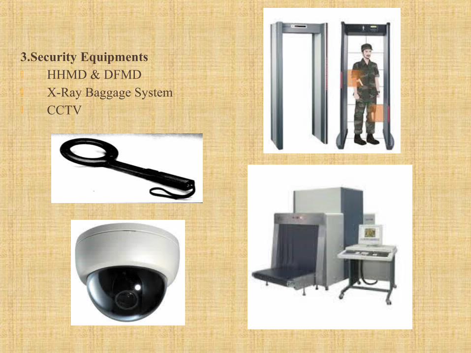
3.Security Equipments HHMD & DFMD X-Ray Baggage System CCTV

Function: It permits voice and data communication for line of sight distances
(distances aren’t too long and not overseas).
Operating frequency: From 118 to 156 MHZ with channel spacing 25 KHZ.Practically, the VHF range from 118 to 136.750 MHz
No. of VHF systems on A/C: 3 VHFs, VHF 3 used for ACARS system.

Sunday, March 15, 2015
VHF2 ANTENNA
VHF3 ANTENNA
VHF1 ANTENNA
VHF ANTENNAS


The AMSS is a computer based system, centred on the AFTN for exchange of Aeronautical messages by means of auto switching for distribution of messages to its destination(s), which works on store and forward principle.
AMSS has four major areas – System Switching Messages Automation

The Instrument Landing System (ILS) provides a means for safe landing of aircraft at airports under conditions of limited visibility.
The ILS also increases the traffic handling capacity of the airport under all weather conditions.
Components of ILS-
1. Localizer 2. Glide Path 3. DME

Distance Measuring Equipment is a vital navigational Aid, which shall provide for continuous and accurate indication in the cockpit of the slant range of an equipped aircraft from an equipped ground reference point.
There are two modes of aircraft interrogations. These are called Search and Track.
The range in nautical miles between the aircraft and the transponder is obtained by the formula :
Total time (Usec) Range = --------------------------- 12.36 Where 12.36 usec is the time taken by the pulse to travel one nautical mile to
and fro.


This ultrasonic distance detector comprising AC power supply, ultrasonic module
make use of a pair of matched ultrasonic piezo ceramic transducers operating at
around 40 kHz each modulated by fixed length tone bursts being fed to the
microcontroller.
Ultrasonic receiver is used in getting reflected burst signals from the object ahead
to calculate the distance by taking into consideration the velocity of sound by a
program fed to the microcontroller to show the distance of the object.
Here microcontroller used is of 8051 family which is of 8bit. The distance is
displayed at a LCD interfaced to the microcontroller.
DISTANCE MEASURING EQUIPMENT (ABSTRACT)

CIRCUIT DIAGRAM

It is a smaller computer Has on-chip RAM, ROM, I/O ports...
RAM ROM
I/O Port
TimerSerial COM Port
Microcontroller
CPU
A single chip

8K Bytes of In-System Programmable (ISP) Flash Memory
Endurance: 10,000 Write/Erase Cycles
4.0V to 5.5V Operating Range
Fully Static Operation: 0 Hz to 33 MHz
256 x 8-bit Internal RAM
32 Programmable I/O Lines
Three 16-bit Timer/Counters
Eight Interrupt Sources
Interrupt Recovery from Power-down Mode
Watchdog Timer


ULTRASONIC TRANSMITTER AND RECIVER
Ultrasonic sensors (also known as transceivers)
work on a principle similar to radar or sonar which
evaluate attributes of a target by interpreting the
echoes from radio or sound waves respectively.
Ultrasonic sensors generate high frequency
sound waves and evaluate the echo which is
received back by the sensor.
Ultrasonic generators use piezoelectric materials such as zinc or lead zirconium
tartrates or quartz crystal.
The material thickness decides the resonant frequency when mounted and
excited by electrodes attached on either side of it.
The medical scanners used for abdomen or heart ultrasound are designed at 2.5
MHz. In this circuit, a 40 kHz transducer is used for object detection in the air
medium.

LIQUID CRYSTAL DISPLAY (LCD)
Most common LCDs connected to the microcontrollers are 16x2 and
20x2 displays.
This means 16 characters per line by 2 lines and 20 characters per line
by 2 lines, respectively.
The standard is referred to as HD44780U, which refers to the controller
chip which receives data from an external source (and communicates
directly with the LCD.

THANKYOU
THANK YOU!