CMOS Image Sensors: Electronic Camera On A Chipericfossum.com/Publications/Papers/CMOS image...
9
CMOS Image Sensors: Electronic Camera On A Chip Eric R. Fossum Center for Space Microelectronics Technology Jet Propulsion Laboratory, California Institute of Technology 4800 Oak Grove Drive, MS 300-3 15 Pasadena, California 9 1109 USA Abstract Recent advancements in CMOS image sensor technology are reviewed, including both passive pixel sensors and active pixel sensors. On-chip analog to digital converters and on-chip timing and control circuits permit realization of an electronic camera-on-a-chip. 1. Introduction Today there are many kinds of electronic cameras with very different characteristics. Camcorders are the most well known electronic camera and capture images with television resolution at 30 frames per second. The camcorder market has driven impressive improvements in charge-coupled device (CCD) technology - the ubiquitous electronic camera sensor technology. Digital still cameras capture higher resolution images (e.g. 1024 x 1024 or higher) at slower pixel rates. These cameras, while presently very expensive for consumer applications, are expected to rapidly drop in price. Low resolution monochrome CCD cameras are very inexpensive. Spaceborne, high resolution electronic cameras occupy the opposite end of the spectrum. New markets are emerging for digital electronic cameras, especially in computer peripherals for document capture and visual communications. If the cost of the camera can be made sufficiently low (e.g. $100 or less per camera) it is expected that most personal computers will have at least one camera peripheral. Even less expensive cameras will find automotive and entertainment applications. Wireless applications of cameras will require ultra low power operation. Very small cameras (e.g. less than 10 cm3) will also permit new markets. Despite the wide variety of applications, all digital electronic cameras have the same basic functions. These are (1) optical collection of photons, i.e. a lens, (2) wavelength discrimination of photons, i.e. filters, (3) detector for conversion of photons to electrons e.g. a photodiode, (4) a method to readout the detectors e.g. a CCD, (5) timing, control and drive electronics for the sensor, (6) signal processing electronics for correlated double sampling, color processing, etc., (7) analog to digital conversion and (8) interface electronics. In a CCD-based system, these electronics often consume several Watts of power (e.g. 5 W-10 W) and, for example, are the major drain on a camcorder battery. The volume and mass of the electronics and power supply constrains the level of miniaturization achievable with the system. Since the CCD’s inception in the early 1970’s, the main focus of research and development has been CCD sensor performance. Criteria include quantum efficiency, optical fill factor (fraction of pixel used for detection), dark current, charge transfer efficiency, readout noise, readout rate, lag, smear, and dynamic range. A desire to reduce optics mass has driven a steady reduction in pixel size. HDTV and scientific applications have driven an increase in array size. Recently, emphasis has been placed on functionality, such as electronic shutter, low power and simplified supply voltages. CMOS image sensors, under sporadic investigation since the 1960’s, and under-nourished in comparison to CCDs, are very apropos for highly integrated, low power imaging systems. Historically, CMOS image sensors have compared unfavorably to CCDs with respect to the above performance criteria. However, recent advances have led to the CMOS active pixel sensor (APS) that has performance competitive with CCDs but with vastly increased functionality, substantially lower system power (10-50 mW), and the potential for lower system cost. It is now straightforward to envision a single chip camera that has integrated timing and control electronics, sensor array, signal processing electronics, analog to digital converter and interface. Such a camera-on-a-chip will have a full digital interface, operate with standard logic supply voltages, and consume power measured in the tens of milliwatts. This paper describes CMOS image sensor technology and the roadmap to achieve a camera-on-a-chip imaging system. 0-7803-2700-4 $4.00 01995 IEEE 1.3.1 IEDM 95- 17
Transcript of CMOS Image Sensors: Electronic Camera On A Chipericfossum.com/Publications/Papers/CMOS image...

CMOS Image Sensors: Electronic Camera On A Chip
Eric R. Fossum
Center for Space Microelectronics Technology Jet Propulsion Laboratory, California Institute of Technology
4800 Oak Grove Drive, MS 300-3 15 Pasadena, California 9 1 109 USA
Abstract
Recent advancements in CMOS image sensor technology are reviewed, including both passive pixel sensors and active pixel sensors. On-chip analog to digital converters and on-chip timing and control circuits permit realization of an electronic camera-on-a-chip.
1. Introduction
Today there are many kinds of electronic cameras with very different characteristics. Camcorders are the most well known electronic camera and capture images with television resolution at 30 frames per second. The camcorder market has driven impressive improvements in charge-coupled device (CCD) technology - the ubiquitous electronic camera sensor technology. Digital still cameras capture higher resolution images (e.g. 1024 x 1024 or higher) at slower pixel rates. These cameras, while presently very expensive for consumer applications, are expected to rapidly drop in price. Low resolution monochrome CCD cameras are very inexpensive. Spaceborne, high resolution electronic cameras occupy the opposite end of the spectrum.
New markets are emerging for digital electronic cameras, especially in computer peripherals for document capture and visual communications. If the cost of the camera can be made sufficiently low (e.g. $100 or less per camera) it is expected that most personal computers will have at least one camera peripheral. Even less expensive cameras will find automotive and entertainment applications. Wireless applications of cameras will require ultra low power operation. Very small cameras (e.g. less than 10 cm3) will also permit new markets.
Despite the wide variety of applications, all digital electronic cameras have the same basic functions. These are (1) optical collection of photons, i.e. a lens, (2) wavelength discrimination of photons, i.e. filters, (3) detector for conversion of photons to electrons e.g. a photodiode, (4) a method to readout the detectors e.g. a CCD, (5) timing, control and drive electronics for the
sensor, (6) signal processing electronics for correlated double sampling, color processing, etc., (7) analog to digital conversion and (8) interface electronics. In a CCD-based system, these electronics often consume several Watts of power (e.g. 5 W-10 W) and, for example, are the major drain on a camcorder battery. The volume and mass of the electronics and power supply constrains the level of miniaturization achievable with the system.
Since the CCD’s inception in the early 1970’s, the main focus of research and development has been CCD sensor performance. Criteria include quantum efficiency, optical fill factor (fraction of pixel used for detection), dark current, charge transfer efficiency, readout noise, readout rate, lag, smear, and dynamic range. A desire to reduce optics mass has driven a steady reduction in pixel size. HDTV and scientific applications have driven an increase in array size. Recently, emphasis has been placed on functionality, such as electronic shutter, low power and simplified supply voltages.
CMOS image sensors, under sporadic investigation since the 1960’s, and under-nourished in comparison to CCDs, are very apropos for highly integrated, low power imaging systems. Historically, CMOS image sensors have compared unfavorably to CCDs with respect to the above performance criteria. However, recent advances have led to the CMOS active pixel sensor (APS) that has performance competitive with CCDs but with vastly increased functionality, substantially lower system power (10-50 mW), and the potential for lower system cost.
It is now straightforward to envision a single chip camera that has integrated timing and control electronics, sensor array, signal processing electronics, analog to digital converter and interface. Such a camera-on-a-chip will have a full digital interface, operate with standard logic supply voltages, and consume power measured in the tens of milliwatts. This paper describes CMOS image sensor technology and the roadmap to achieve a camera-on-a-chip imaging system.
0-7803-2700-4 $4.00 01995 IEEE
1.3.1
IEDM 95- 17

2. Historical Background
Before CMOS APS and before CCDs there was MOS. In the 1960’s there were numerous groups working on solid-state image sensors with varying degrees of success using NMOS, PMOS and bipolar processes. For example, in 1963, Morrison reported a structure (that is now referred to as a computational sensor) that allowed determination of a light spot’s position using the photoconductivity effect’. The scanistor was reported in 1964 by IBM2. The scanistor used an array of npn junctions addressed through a resistive network to produce an output pulse proportional to the local incident light intensity. In 1966 Westinghouse reported a 50x50 element monolithic array of photo transistor^^. All of these sensors had an output signal proportional to the instantaneous local incident light intensity and did not perform any intentional integration of the optical signal. As a consequence, the sensitivity of these devices was low and they required gain within the pixel to enhance their performance.
In 1967, Weckler at Fairchild suggested operating p-n junctions in a photon flux integrating mode4. The photocurrent from the junction is integrated on a reverse- biased p-n junction capacitance. Readout of the integrated charge using a PMOS switch was suggested. The signal charge, appearing as a current pulse, could be converted to a voltage pulse using a series resistor. A 1 OOx 100 element array of photodiodes was reported in 196S5. Weckler later called the device a reticon and formed Reticon to commercialize the sensor.
Also in 1967, RCA reported a thin-film transistor (TFT) solid-state image sensor using CdS/CdSe TFTs and photoconductors6. The 180x1 80 element array included self-scanning complementary logic circuitry for sequentially addressing pixels. A battery operated wireless camera was also reported to have been constructed to demonstrate the array.
Also active at that time was Plessey in the UK. In a 1968 seminal paper, Noble described several configurations of self-scanned silicon image detector arrays7. Both surface photodiodes and buried photodiodes (to reduce dark current) were described. Noble also discussed a charge integration amplifier for readout, similar to that used later by others. In addition, the first use of a MOS source-follower transistor in the pixel for readout buffering was reported. An improved model and description of the operation of the sensor was reported by Chamberlain in 1969*. The issue of fixed- pattern noise (FPN) was explored in a 1970 paper by Fry, Noble, and Rycroft’.
Until recently, FPN has been considered the primary problem with MOS and CMOS image sensors. In 1970, when the CCD was first reported”, its relative freedom from FPN was one of the major reasons for its adoption over the many other forms of solid-state image sensors. The smaller pixel size afforded by the simplicity of the CCD pixel also contributed to its embrace by industry.
The 1970’s saw a great deal of activity in CCDs but little reported activity on other image sensors. In the late 1970’s and early 1980’s Hitachi continued the development of MOS image sensors’’ for camcorder- type applications, including single chip color imagersi2. Temporal noise in MOS sensors started to lag behind the noise achieved in CCDs, and by 1985, Hitachi combined the MOS sensor with a CCD horizontal shift registeri3. In 1987, Hitachi introduced a simple on-chip technique to achieve variable exposure times and flicker suppression from indoor lightingi4. However, perhaps due to residual temporal noise, especially important in low light conditions, Hitachi abandoned its MOS approach to sensors.
3. Modern CMOS image sensors
The 1990’s have seen a resurgent interest in CMOS image sensors. The major reason for the interest is related to miniaturized and cost effective imaging systems. CMOS-based image sensors offer the potential opportunity to integrate a significant amount of VLSI electronics on-chip and reduce component and packaging costs. CCD technology, on the other hand, has become quite specialized and, in general, is not well- suited to CMOS integration due to voltage, capacitance and process constraints.
Contributing to the recent activity in CMOS image sensors is the steady, exponential improvement in CMOS technology. The rate of minimum feature size decrease has outpaced similar improvements in CCD technology. Furthermore, sensor pixel size is limited by both optical physics and optics cost, making moot the CCD’s inherent pixel size advantage. Recent progress in on- chip signal processing has also reduced FPN to acceptable levels.
There are three predominant approaches to pixel implementation in CMOS: passive pixel, photodiode- type active pixel, and photogate-type active pixel. These are described below. There are also several ways to make pn junction photodiodes in CMOS’’, but generally n+ diodes on a p/p+ epi substrate in an n-well process give the most satisfactory results.
1.3.2 IS-IEDM 95

- - - II - -__ /r 5 -
Cheap Lens L- t 5
1970 1975 1980 1985 1990 1995 2000 2005
Year
Figure 1. The steadily increasing ratio between pixel size and minimum feature size permits the use of CMOS circuitry within each pixel.
Passive pixel approach The passive photodiode pixel approach remains virtually unchanged since first suggested by Weckler in 1967. The passive pixel concept is shown below in Figure 2 and is the basis for photodiode arrays produced by EG&G Reticon and Hitachi, and more recently, by Edinburgh University and VLSI Vision in S ~ o t l a n d ' ~ , ' ~ , and by Linkoping University and IVP in Significant levels of integration have been achieved with the passive pixel approach, including on-chip analog-to- digital conversion (ADC) described later.
Tx -I--
n+ COL'BUS
Figure 2 Passive pixel schematic and potential well When the transfer gate TX is pulsed, photogenerated charge integrated on the photodiode is shared on the bus capacitance
The passive pixel features excellent quantum efficiency since the photodiode is not covered by polysilicon. With only a single transistor per pixel required for readout, it has the smallest possible pixel pitch for a given optical fill factor. A second selection transistor has sometimes been added to permit true X-Y addressing and reduce bus capacitance. Pixel pitch is typically lox the minimum feature size. Small pixels are desired for small inexpensive die size and small, lightweight optics.
Much larger pixels have been used for document imaging". Page-sized image sensors (7.7" x 9.6") using amorphous silicon and constructed with a passive pixel architecture have been demonstrated with a dynamic range of 1 04- 1 05.
The major problems with the passive pixel are its noise level and scalability. Noise on a passive pixel is typically of the order of 250 electrons r.m.s., compared to commercial CCDs that achieve less than 20 electrons r.m.s. of read noise. The passive pixel also does not scale well to larger array sizes and or faster pixel readout rates. This is because increased bus capacitance and faster readout speed both result in higher readout noise. To date, passive pixel sensors suffer from large fixed pattem noise, though this is not a fundamental problem.
Active pixel aDproach It was quickly recognized, almost as soon as the passive pixel was invented, that the insertion of a buffedamplifier into the pixel could potentially improve the performance of the pixel. A sensor with an active amplifier within each pixel is referred to as an active pixel sensor or APS. Since each amplifier is only activated during readout, power dissipation is minimal and generally less than a CCD. Non-CMOS APS devices have been developed that have excellent performance such as the charge-modulation devices (CMD)22 but these require a specialized fabrication process. In general, APS technology has many advantages over C C D S . ~ ~
The CMOS APS trades pixel fi l l factor for improved performance using the in-pixel amplifier. Pixels are typically designed for a fill factor of 20-30%. Loss in optical signal is more than compensated by reduction in read noise for a net increase in signal to noise ratio and dynamic range. Microlenses are commonly employed with low fill factor interline C C D S ~ ~ , ~ ' and can recover the lost optical signal. The simple, polyimide microlense refracts incident radiation from the circuitry region of the pixel to the detector region. The microlense can improve optical fill factor by 3-fold so that the net optical aperture for the detector is 60%-80%.
Photodiode-Que APS The photodiode-type APS was described by P.Noble in 1968 and has been under investigation by F.Andoh at NHK in Japan since the late 1 9 8 O ' ~ * " ~ ~ , ~ ' in collaboration with Olympus, and later, Mitsubishi Electric. A diagram of the photodiode-type APS is shown below in Figure 4. In a version of the NHWOlympus device, the photodiode is not used for optoelectronic conversion; instead an a-Se thin film covers the pixel and the sensor is operated in an electron-bombarded mode. A similar device with an a- Si:H overlayer was described by Huang and Ando in 19903' but operated in a conventional optically illuminated mode. The overlayer is used to improve
1 . 3 . 3
IEDM 95-19

effective fill factor. The structure of Figure 4 was also employed by JPL in a 128x128 element array that had on-chip timing, control, correlated double sampling and fixed pattern noise suppression circuitry33, as shown in Figure 5 .
1 Tr Dp-we, , Ta Ty IstAL 1 n- sub
Figure 3 Crosssection of NHK CMOS APS structure with a-Se overlayer for electron bombardment from photocathode
More complicated pixels can be constructed to improve functionality and to a lesser extent, performance. Hamamatsu reported on an improved sensor that used a transfer gate between the photodiode and the source follower gate34. The transfer gate keeps the photodiode at constant potential and increases output conversion gain by reducing capacitance but introduces lag. The Hamamatsu sensor also improved fixed pattern noise using a feedback technique. More complication was added by the Technion to permit random access and electronic shuttering at a significant expense of pixel size . 35
VDD
n+
I COL BUS
Figure 4 A photodiode-type active pixel sensor (APS) The voltage on the photodiode is buffered by a source follower to the column bus. selected by RS-row select The photodiode is reset by transistor RST
Photodiode-type APS pixels have high quantum efficiency as there is no overlying polysilicon. The read noise is limited by the reset noise on the photodiode since correlated double sampling is not easily implementable, and is typically 75- 100 electrons r.m.s. The photodiode-type APS uses three transistors per pixel and has a typical pixel pitch of 15x the minimum feature size. The photodiode APS is suitable for most mid to low performance applications, and its performance improves for smaller pixel sizes since the reset noise scales as C”*, where C is the photodiode capacitance. Preliminary measurements at JPL indicate that the dark current radiation sensitivity of the photodiode-type APS is superior to the photogate-type APS described next.
Figure 5. A 128~128photodiode-type CMOS APS with on chip timing control, correlated double sampling and fixed pattern noise suppression ciruitry Readout window and interframe integration time is asynchronously commanded. JPL chip requires only +5V and clock to produce high qualiy analog video o~tput’~.
Photogate-gpe APS The photogate APS was introduced by JPL in 199336,37 for high performance scientific imaging and low light applications. The photogate APS combines CCD benefits and X-Y readout, and is shown schematically below in Figure 6. Signal charge is integrated under a photogate. For readout, an output floating diffusion is reset and its resultant voltage measured by the source follower. The charge is then transferred to the output diffusion by pulsing the photogate. The new voltage is then sensed. The difference between the reset level and the signal level is the output of the sensor. This correlated double sampling suppresses reset noise, l/f noise, and fixed pattern noise due to threshold voltage variations.
VDD
, J . J
PG RST TX iL?l Rsilu
I COL BUS
VB
Figure 6 Photogate-type APS pixel schematic and potential wells Transfer of charge and correlated double sampling permits low noise operation
The photogate and transfer gate ideally overlap using a double poly process. However, the insertion of a floating diffusion between PG and TX has minimal effect on circuit performance and permits the use of single poly p r o c e s s e ~ ~ ~ . The photogate-type APS uses five transistors per pixel and has a pitch typically equal to 20x the minimum feature size. Thus, to achieve a 10 pm pixel pitch, a 0.5 pm process must be employed.
1.3.4
20-IEDM 95

A 0.25 pm process would permit a 5 pm pixel pitch. The floating diffusion capacitance is typically of the order of 10 fF yielding a conversion gain of 10- 20 pV/electron. Subsequent circuit noise is of the order of 150-250 pV r.m.s., resulting in a readout noise of 10- 20 electrons r.m.s., with the lowest noise demonstrated to date of 13 electrons r . m . ~ . ~ ~
Figure 7. Close up of photogate pixels implemented using 1.2 pm design rules with 20.4 pm pixel pitch by JPL.
The architecture of the CMOS APS is typically designed to read out a row at a time, as selected by a decoder, with the reset and signal levels held on sampling capacitors at the bottom of the column. The column capacitors are selected by a decoder for buffered readout. Thus, the sensor can be read out in a sequential or nearly random access subsampled fashion, or by selecting window for readout to enable electronic zoom.
a small
Figure 8. Image of a US $I bill taken with a JPL 256x256 element CMOS APS showing excellent image qualily with no artifacts.
A 256x256 CMOS APS with 20 pm pixels implemented using 0.9 pm CMOS, without timing and control was reported by AT&T and JPL40. Motion detection was implemented by changing the timing of the sensor so that the previous frame is stored on the floating diffusion while the next frame is integrated under the photogate.
Output is the difference between successive frames. A 1024x1024 element CMOS APS with 10 pm pixels implemented using 0.5 pm CMOS, also without timing and control, has been fabricated and tested and will be reported soon by AT&T and JPL4‘. A 256x256 element CMOS APS with 20.4 pm pixels implemented using a 1.2 pm n-well process with timing and control logic will be reported by JPL39. This sensor requires only +5V and clock to produce analog video output. Variable integration time and window of interest readout can be commanded asynchronously. The chip can be readout in normal mode or in motion detection mode.
Figure 9. 1024x1 024 element photogate CMOS APS with I0 p m pixel pitch fabricated using 0.5 pm design rules by AT&T/JPL.
Other pixels A non-integrating 5 12x5 12 element photodiode-type APS was reported by IMEC with a 6.6 pm pixel This sensor operates in a non-integrating current mode with logarithmic response. FPN was corrected by means of hot-carrier-induced threshold voltage shift.
The pinned photodiode, developed for interline transfer CCDs, features high quantum efficiency (esp. in the blue), low dark current, and low noise readout. The pinned photodiode has been combined with CMOS APS readout by JPL/Kodak to achieve high performance pixel response43.
A photogate CMOS APS with a floating-gate sense amplifier that allows multiple non-destructive, doubly sampled reads of the same signal was developed by JPL for use with oversampled column-parallel A D C S ~ ~ .
A floating gate sensor with a simple structure was reported by JPL/Olympus4’. This sensor used a floating gate to collect and sense the photosignal and features a compact pixel layout with complete reset.
1.3.5
IEDM 95-21

There has been significant work on retina-like CMOS sensors with non-linear, adaptive response46. While their utility for electronic image capture has not yet been demonstrated, their very large dynamic range and similarity to the response of the human eye offer intriguing possibilities for on-chip intelligent imaging.
Analog signal processinp, On-chip analog signal processing can be used to improve the performance and functionality of the CMOS image sensor. 3PL has developed a delta-difference sampling (DDS) approach to suppress FPN peak-to-peak to 0.1% of saturation Other examples of signal processing demonstrated in CMOS image sensors include smoothing using neuronMOSFETs4’, programmable amplification4*, multiresolution imaging49, video compressions0, and intensity sorting5’. Continued improvement in analog signal processing performance and functionality is expected. Other computational-type optical sensors have been demonstrated that use CMOS analog signal p r o c e s ~ i n g ~ ~ , ~ ~ .
On-chit, ADC On-chip ADC is desired for image sensors to simplify system design and achieve a single chip imaging system. One of the most significant benefits of a CMOS-based image sensor is its easy integration with an on-chip analog-to-digital converter. The ADC must have low power dissipation, not occupy too much chip area, yet achieve at least 8 bit resolution at 10 megapixelhec data rates. Many different architectures are possible as the design trade space is relatively flat54. It is possible to have a single ADC for the entire array operating at high conversion rate, an ADC for each pixel operating at the frame rate, or an ADC for each column of the array. The latter architecture is referred to as column-parallel and represents a good trade of parallelism and chip area for lower power. Several Swedish papers have been presented that described column-parallel ADCs integrated with passive pixel CMOS image These sensors generally use the single-slope ADC conversion technique. A column parallel 8-bit single slope ADC has been integrated with a small CMOS APS by JPL55, and a larger array with the same ADC was demonstrated by JPL/AT&Ts6. Since the CMOS APS has a dynamic range of 13-14 bits, greater resolution is desirable. Oversampled ADCs in a column parallel architecture were demonstrated by Mendis at JPL44,55 but not integrated with an image sensor. Pixel level oversampled ADC has been explored by Stanfords7 but requires high frame rate readout. A single-bit ADC
integrated with a photodiode-type CMOS developed for high speed binary imaging5*.
APS was
Figure 10. A 176x144 element, 20 pm pitch CMOS APS with 176 8-b single slope ADCs achieving 30 Hz operation with 35 m W power at 3.5Vsupply voltage by AT&T/JPL.
4. Roadmap for Camera-on-a-Chip
All the component technologies to realize a CMOS electronic camera-on-a-chip have been developed. Single chip cameras based on the lower performance passive pixel are already available. Higher performance single-chip cameras based on the CMOS APS technology are expected to emerge shortly. Improvement in on-chip ADC technology to take advantage of the high dynamic range is needed. Backend processes for color filter arrays and microlenses are nearly as complicated as the standard CMOS process and add significantly to cost. A single chip color camera can be expected in the next year or two. Standards for digital cameras need to be developed to enable the wider development of the technology.
4. Impact of CMOS Scaling Trends
The future prospects for CMOS image sensors are bright. The effect of predictable trends in CMOS technology, based on the industry standard technology roadmap, were examined by Fossum and Wong of JPL/IBMS9. To at least 0.25 pm minimum feature sizes, it appears that the standard CMOS process will permit the fabrication of high performance CMOS image sensors.
The most obvious problem, but the easiest to correct, is the trend toward the use of silicides. Silicides are optically opaque and detrimental to image sensing. A silicide-blocking mask is available in some processes already. The switchover to silicon-on-insulator (SOI) technology will be problematic for the sensors due to the minimal absorption of photons in thin silicon films, but such a switchover is not expected to generally occur until
1.3.6
22-IEDM 95
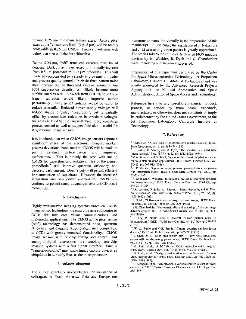
beyond 0.25 pm minimum feature sizes. Active pixel sizes at the “cheap lens limit” (e.g. 5 pm) will be readily achievable in 0.25 pm CMOS. Passive pixel sizes well below that size will also be achievable.
Below 0.25 pm, “off’ transistor currents may be of concern. Dark current is expected to minimally increase from 0.5 pm processes to 0.25 pm processes. This will likely be compensated by a steady improvement in wafer and process quality control. Intrinsic fixed pattern noise may increase due to threshold voltage mismatch, but FPN suppression circuitry will likely become more sophisticated as well. A switch from LOCOS to shallow trench isolation would likely improve sensor performance. Deep trench isolation would be useful to reduce crosstalk. Reduced power supply voltages will reduce analog circuitry “headroom”, but is partially offset by concomitant reduction in threshold voltages. Increases in DRAM chip size will drive improvements in process control as well as stepper field size -- useful for larger format image sensors.
It is inevitable that when CMOS image sensors capture a significant share of the electronic imaging market, process deviations from standard CMOS will be made to permit product differentiation and improved performance. This is already the case with analog CMOS for capacitors and isolation. Use of the pinned photodiode43 will improve quantum efficiency and decrease dark current. Double poly will permit efficient implementation of capacitors. However, the increased integration and low power enabled by CMOS will continue to permit many advantages over a CCD-based technology.
5. Conclusions
Highly miniaturized imaging systems based on CMOS image sensor technology are emerging as a competitor to CCDs for low cost visual communications and multimedia applications. The CMOS active pixel sensor (APS) technology has demonstrated noise, quantum efficiency, and dynamic range performance comparable to CCDs with greatly increased functionality. CMOS image sensors with on-chip timing and control, and analog-to-digital conversion are enabling one-chip imaging systems with a full digital interface. Such a “camera-on-a-chip’’ may make image capture devices as ubiquitous in our daily lives as the microprocessor.
6. Acknowledgments
The author gratefully acknowledges the assistance of colleagues in North America, Asia and Europe too
numerous to name individually in the preparation of this manuscript. In particular, the assistance of J. Nakamura and J. Li in tracking down papers is greatly appreciated. The stories told to me of the early days of MOS imaging devices by G. Weckler, R. Dyck and S. Chamberlain were interesting and are also appreciated.
Preparation of this paper was performed by the Center for Space Microelectronics Technology, Jet Propulsion Laboratory, California Institute of Technology, and was jointly sponsored by the Advanced Research Projects Agency and the National Aeronautics and Space Administration, Office of Space Access and Technology.
Reference herein to any specific commercial product, process, or service by trade name, trademark, manufacturer, or otherwise, does not constitute or imply its endorsement by the United States Government, or the Jet Propulsion Laboratory, California Institute of Techno logy.
7. References
I S.Morrison, “A new type of photosensitive junction device,” Solid- State Electronics, vol. 5, pp. 485-494 (1963).
J. Horton, R. Mazza, and H. Dym, “The scanistor - a solid state image scanner,” Proc. IEEE vol. 52, pp. 1513-1528 (1964).
M.A. Schuster and G. Strull, “A monolithic mosaic of photon sensors for solid state imaging applications,” IEEE Trans. Electron Dev., vol.
G. P. Weckler. “Operation of p-n junction photodetectors in a photon flux integration mode,” IEEE J. Solid-state Circuits, vol. SC-2, pp.
’ R. Dyck and G. Weckler, “Integrated arrays of silicon photodetectors for image sensing,” IEEE Trans. Electron Dev. vol. ED-I5(4), pp.
P.K. Weimer, G. Sadasiv, J. Meyer, L. Meray-Howath, and W. Pike, “A self-scanned solid-state image sensor,” Proc. IEEE, vol. 55, pp.
’ P. Noble, “Self-scanned silicon image detector arrays,” IEEE Trans. Electron Dev. vol. ED-15(4), pp. 202-209 (1968).
S.G. Chamberlain, “Photosensitivity and scanning of silicon image detector arrays,” IEEE J. Solid-state Circuits, vol. SC-4(6) pp. 333- $42 (1969).
P. Fry, P. Noble, and R. Rycroft, “Fixed pattern noise in photomatrices,” IEEE J. Solid-state Circuits, vol. SC-5(5) pp. 250-254 (1970). I ” W. S. Boyle and G.E. Smith, “Charge coupled semiconductor devices,” Bell Syst. Tech. J., vol. 49, pp. 587-593 (1970). ” S. Ohba, et al., “MOS area sensor: part I1 - low noise MOS area sensor with anti-blooming photodiodes,” IEEE Trans. Electron Dev.
I * M. Aoki, et al., “A 2/3” format MOS single-chip color imager,” IEEE Trans. Electron Dev., vol. ED-29(4) pp. 745-750, (1982). l 3 H. Ando, et al., “Design consideration and performance of a new MOS imaging device,” IEEE Trans. Electron Dev., vol. ED-32(5), pp.
l4 T. Kinugasa, et al., “An electronic variable shutter system in video camera use,” IEEE Trans. Consumer Electronics, vol. CE-33 pp. 249- 255 (1987).
ED-13, pp. 907-912 (1966).
65-73 ( I 967).
196-201 (1968).
1591-1602 (1967).
vol. ED-27(8), pp. 1682-1687 (1980).
1484-1489 (1985).
1 . 3 . 7 IEDM 95-23

P. Aubert, H. Oguey, and R. Vuillemier, “Monolithic optical position encoder with on-chip photodiodes,” IEEE J. Solid-state Circuits, vol. SC-32, pp. 465-472 (1988).
D. Renshaw, P. Denyer, G. Wang, and M. Lu, “ASIC image sensors,” Proc. IEEE ISCAS pp. 3038-3041 (1990). l 7 P. Denyer, D. Renshaw, G. Wang, and M. Lu, “CMOS image sensors for multimedia applications,” IEEE Proc. CICC. pp. 1 1.5.1 - 11.5.4 (1993). I* K. Chen, M. Afghahi, P. Danielsson, and C. Svensson, “PASIC - A Processor-ND converter sensor integrated circuit,” IEEE ISCAS, pp.
R. Forchheimer, P. Ingelhag, and C. Jansson, “MAPP2200: a second generation smart optical sensor,” Proc. of SPIE vol. 1659 lmage Processing and Interchange, pp. 2-1 1 (1992).
C. Jansson, 0. Ingelhag, C. Svensson, and R. Forchheimer, “An addressable 256x256 photodiode image sensor array with an 8-bit digital output,” Analog Integrated Circuits and Signal Processing, vol.
X. Wu, R. Street, R. Weisfield, D. Begelson, W. Jackson, D. Jared, S. Ready and R. Apte, “Large format a-Si:H 2-dimensional array as imaging devices,” 1995 IEEE Workshop on CCDs and Advanced Image Sensors, Dana Point, CA, April 20-22 1995.
K. Matsumoto, et al., “A new MOS phototransistor operating in a non-destructive readout mode,” Jpn J. Appl. Phys., vol. 24(5) pp.
A. Yusa, et al., “SIT image sensor: design considerations and characteristics,” IEEE Trans. Electron Dev., vol. ED-33(6) pp. 735- 742 (1986).
N. Tanaka, et al., “A 310 pixel bipolar imager (BASIS),” IEEE Trans. Electron Dev., vol. ED-37(4) pp. 964-971 (1990).
J. Hynecek, “A new device architecture suitable for high resolution and high performance image sensors,” IEEE Trans. Electron Dev. vol.
E.R. Fossum, “Active Pixel Sensors -- Are CCDs Dinosaurs?,” in CCDs and Optical Sensors 111, Proc. SPIE vol. 1900, pp. 2-14, (1993).
Y. Ishihara and K. Tanigaki, “A high sensitivity IL-CCD image sensor with monolithic resin lens array,” IEEE IEDM Tech. Dig. pp.
Y. Sano, T. Nomura, H. Aoki, S. Terakawa, H. Kodama, T. Aoki, and Y. Hiroshima, “Submicron spaced lens array process technology for a high photosensitivity CCD image sensor,” IEEE IEDM Tech. Dig. pp. 283-286 (1990).
F. Andoh, K. Taketoshi, J. Yamazaki, M. Sugawara, Y. Fujita, K. Mitani, Y. Matuzawa, K. Miyata, and S. Araki, “A 250,000 pixel image sensor with FET amplification at each pixel for high speed television cameras,” IEEE ISSCC Tech. Dig. pp. 212-213 (1990).
H. Kawashima, F. Andoh, N. Murata, K. Tanaka, M. Yamawaki, and K. Taketoshi, “A 1/4 inch format 250,000 pixel amplifier MOS iamge sensor using CMOS process,” IEEE IEDM Tech. Dig. pp. 575- 578 (1993). 3 1 M. Sugawara, H. Kawashima, F. Andoh, N. Murata, Y. Fujita, and M. Yamawaki, “An amplified MOS imager suited for image I;1:.ocessing,” IEEE ISSCC Tech. Dig. pp. 228-229 (1994).
Z-S. Huang, and T. Ando, “A novel amplified image sensor with a- Si:H photoconductor and MOS transistors,” IEEE Trans. Electron
R.H. Nixon, S.E. Kemeny, C.O. Staller, and E.R. Fossum, “128x128 CMOS photodiode-type active pixel sensor with on-chip timing, control and signal chain electronics,” in Charge-Couoled Devices and Solid-state Ootical Sensors V, Proc. SPIE vol. 2415, paper 34 (1995).
M. Kyomasu, “New MOS imager using photodiode as current source,” IEEE J. Solid-state Circuits, vol. 26(8) pp. 11 16-1 122
0. Yadid-Pecht, R. Ginosar, and Y. Diamand, “A random access photodiode array for intelligent image capture,” IEEE. Trans. Electron Dev. vol. 38(8) pp. 1772-1780 (1991).
16
1705-1708 (1990).
20
4, pp. 37-49 (1993). 21
22
L323-L325 (1985). 23
24
25
ED-35(3) pp. 646-652 (1988). 26
27
497-500 (1983). 28
29
30
p. vol. ED-37(6) pp. 1432-1438 (1990).
34
$51991).
S. Mendis, S. Kemeny and E.R. Fossum, “A 128x128 CMOS active pixel image sensor for highly integrated imaging systems,”IEEE IEDM Tech. Dig., pp. 583-586, (1993).
S.Mendis, S.E. Kemeny and E.R. Fossum, “CMOS active pixel image sensor,” IEEE Trans. Electron Devices, vol. 41(3), pp. 452-453
S. Mendis, S.E. Kemeny, R. Gee, B. Pain, and E.R. Fossum, “Progress in CMOS active pixel image sensors,” in Charge-Coupled Devices and Solid State Optical Sensors IV, Proc. SPIE vol. 2172, pp.
36
37
$994).
19-29 (1994). 39
40 R. Nixon, C. Staller and E.R. Fossum, unpublished. A. Dickinson, B. Ackland, E-S. Eid, D. Inglis and E.R. Fossum, “A
256x256 CMOS active pixel image sensor with motion detection,” IEEE ISSCC Tech. Dig., pp. 226-227, (1995).
A. Dickinson, S. Mendis, D. Inglis, K. Azadet, P. Jones and E.R. Fossum, unpublished. 42 N. Ricquier and B. Dierickx, “Active pixel CMOS image sensor with on-chip non-uniformity correction,” 1995 IEEE Workshop on CCDs and Advanced Image Sensors, Dana Point, CA, April 20-22 1995.
P.Lee, R. Gee, M. Guidash, T.Lee, and E.R. Fossum, “An active pixel sensor fabricated using CMOS/CCD process technology,” 1995 IEEE Workshop on CCDs and Advanced Image Sensors, Dana Point, CA, April 20-22 1995. 44 S. Mendis, B. Pain, R. Nixon, and E.R. Fossum, “Design of a low- light-level image sensor with an on-chip sigma-delta analog-to-digital conversion,” in CCDs and Outical Sensors 111, Proc. SPIE vol. 1900, pp. 3 1-39 (1 993) 4’ J. Nakamura, S.E. Kemeny and E.R. Fossum, “A CMOS active pixel image sensor with simple floating gate pixels,” IEEE Trans. Electron Dev. vol. ED-42(9) pp. 1693-1694 (1995).
C. Mead, “A sensitive electronic photoreceptor,” 1985 Chapel Hill Conference on VLSI, pp. 463-471 (1985).
J . Nakamura and E.R. Fossum, “Design of an image sensor using a neuron MOSFET with image smoothing capability,” in Charge- Coupled Devices and Solid State Outical Sensors IV, Proc. SPIE vol.
Z. Zhou, S.E. Kemeny, B. Pain, R.C. Gee, and E.R. Fossum, “A CMOS Active Pixel Sensor with Amplification and Reduced Fixed Pattern Noise,” 1995 IEEE Workshop on CCDs and Advanced Image Sensors, Dana Point, CA, April 20-22 1995.
S. E. Kemeny, B. Pain, R. Panicacci, L. Matthies, and E.R. Fossum, “CMOS Active Pixel Sensor Array with Programmable Multiresolution Readout,” 1995 IEEE Workshop on CCDs and Advanced Image Sensors, Dana Point, CA, April 20-22 1995.
K. Aizawa, H. Ohno, Y. Egi, T. Hamamoto, M. Hatori, and J. Yamazaki, “On sensor video compression,” 1995 IEEE Workshop on CCDs and Advanced Image Sensors, Dana Point, CA, April 20-22 1995.
V. Brajovic and T. Kanade, “New massively parallel technique for global operations in embedded imagers,” 1995 IEEE Workshop on CCDs and Advanced Image Sensors, Dana Point, CA, April 20-22 1995.
J. Kramer, P. Sietz, and H. Bakes, “Industrial CMOS technology for the intration of optical metrology systems (photo-ASICs),” Sensors and Actuators, vol. A34, pp. 21-30 (1992). 53 R. Miyagawa and T. Kanade, “Integration-time based computational sensors,” 1995 IEEE Workshop on CCDs and Advanced Image Sensors, Dana Point, CA, April 20-22 1995.
B. Pain and E.R. Fossum, “Approaches and analysis for on-focal- plane analog-to-digital conversion,” in Infrared Readout Electronics - 11, Proc. SPIE vol. 2226, pp. 208-218 (1994). ’’ S. Mendis, CMOS Active Pixel Image Sensors and On-Chio Signal Processinv, Ph.D. Thesis, Columbia University 1995.
A. Dickinson, S. Mendis, D. Inglis, K. Azadet, and E. Fossum, “CMOS digital camera with column parallel analog-to-digital
41
43
46
41
2172, pp. 30-37 (1994). 4x
49
50
51
52
54
56
1 . 3 . 8
24-IEDM 95

conversion architecture,” 1995 IEEE Workshop on CCDs and Advanced Image Sensors, Dana Point, CA, April 20-22 1995.
B. Fowler, A. Gamal, and D. Yang, “A CMOS area image sensor with pixel-level A/D conversion,” IEEE ISSCC Tech. Dig. pp. 226- 227 (1994).
R. Panicacci, S. Kemeny, P. Jones, C. Staller and E. Fossum, “High 5x
speed CMOS binary active pixel image sensor,” 1995 IEEE Workshop on CCDs and Advanced Image Sensors, Dana Point, CA, April 20-22 1995.
E.R. Fossum and P. Wong, “Future prospects for CMOS active pixel sensors,” 1995 IEEE Workshop on CCDs and Advanced Image Sensors, Dana Point, CA, April 20-22 1995.
57
5Y
IEDM 95-25