
Cm eib manual_201009_en
48
Communication with LOGO! on EIB according to Konnex standard Manual Edition 09/2010
-
Upload
marcio-miranda-dantas -
Category
Education
-
view
27 -
download
0
Transcript of Cm eib manual_201009_en
Communication with LOGO! on EIB according to Konnex standard
Manual Edition 09/2010


�CM EIB�
___________________
___________________
___________________
___________________
___________________
___________________
___________________
___________________
___________________
___________________
LOGO!
CM EIB
Operating Instructions
09/2010 J31069-D1262-U003-A2-7618
Preface
Description
1
Application planning
2
Installation
3
Connecting
4
Commissioning
5
Service and maintenance
6
Functions
7
Technical data
8
List of abbreviations
A

Legal information
Legal information Warning notice system
This manual contains notices you have to observe in order to ensure your personal safety, as well as to prevent damage to property. The notices referring to your personal safety are highlighted in the manual by a safety alert symbol, notices referring only to property damage have no safety alert symbol. These notices shown below are graded according to the degree of danger.
DANGER indicates that death or severe personal injury will result if proper precautions are not taken.
WARNING indicates that death or severe personal injury may result if proper precautions are not taken.
CAUTION with a safety alert symbol, indicates that minor personal injury can result if proper precautions are not taken.
CAUTION without a safety alert symbol, indicates that property damage can result if proper precautions are not taken.
NOTICE indicates that an unintended result or situation can occur if the corresponding information is not taken into account.
If more than one degree of danger is present, the warning notice representing the highest degree of danger will be used. A notice warning of injury to persons with a safety alert symbol may also include a warning relating to property damage.
Qualified Personnel The product/system described in this documentation may be operated only by personnel qualified for the specific task in accordance with the relevant documentation for the specific task, in particular its warning notices and safety instructions. Qualified personnel are those who, based on their training and experience, are capable of identifying risks and avoiding potential hazards when working with these products/systems.
Proper use of Siemens products Note the following:
WARNING Siemens products may only be used for the applications described in the catalog and in the relevant technical documentation. If products and components from other manufacturers are used, these must be recommended or approved by Siemens. Proper transport, storage, installation, assembly, commissioning, operation and maintenance are required to ensure that the products operate safely and without any problems. The permissible ambient conditions must be adhered to. The information in the relevant documentation must be observed.
Trademarks All names identified by ® are registered trademarks of the Siemens AG. The remaining trademarks in this publication may be trademarks whose use by third parties for their own purposes could violate the rights of the owner.
Disclaimer of Liability We have reviewed the contents of this publication to ensure consistency with the hardware and software described. Since variance cannot be precluded entirely, we cannot guarantee full consistency. However, the information in this publication is reviewed regularly and any necessary corrections are included in subsequent editions.
Siemens AG Industry Sector Postfach 48 48 90026 NÜRNBERG GERMANY
J31069-D1262-U003-A2-7618 Ⓟ 10/2010
Copyright © Siemens AG 2010. Technical data subject to change
CM EIB Operating Instructions, 09/2010, J31069-D1262-U003-A2-7618 5
Preface
Purpose and content of the manual This manual informs you about the installation, connection, commissioning, and use of the CM EIB communication module for LOGO!.
Trademarks LOGO! is a registered trademark of Siemens AG.
Guide The manual is divided into 8 chapters: ● Description ● Installation ● Connection ● Commissioning ● Servicing ● Functions ● Technical data The manual also contains a list of abbreviations in the appendix following the chapters.
Target group The manual is aimed at users who already have experience with the LOGO! automation system and now want to use the KNX/EIB building bus.
Scope of the manual The manual is valid for CM EIB for LOGO! with the MLFB no. 6BK1700-0BA00-0AA2 and describes product version 1.
Additional differences to previous devices (6BK1700-0BA00-0AA0) ● Expansion of analog output functionality to 8 through multiplexing ● Availability of local analog inputs and outputs of LOGO! on the EIB ● Time synchronization via the EIB. Here, LOGO! can be both time-of-day master and slave
clock. ● Use of LOGO! as roller blind control in combination with an EIB pushbutton ● Dimming with LOGO!
Preface
CM EIB 6 Operating Instructions, 09/2010, J31069-D1262-U003-A2-7618
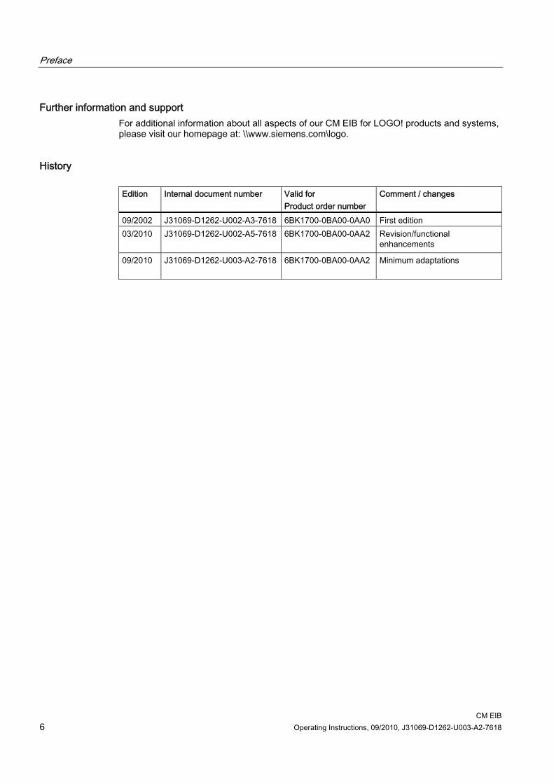
Further information and support For additional information about all aspects of our CM EIB for LOGO! products and systems, please visit our homepage at: \\www.siemens.com\logo.
History Edition Internal document number Valid for
Product order number Comment / changes
09/2002 J31069-D1262-U002-A3-7618 6BK1700-0BA00-0AA0 First edition 03/2010 J31069-D1262-U002-A5-7618 6BK1700-0BA00-0AA2
Revision/functional enhancements
09/2010 J31069-D1262-U003-A2-7618 6BK1700-0BA00-0AA2
Minimum adaptations
CM EIB Operating Instructions, 09/2010, J31069-D1262-U003-A2-7618 7
Table of contents
Preface ...................................................................................................................................................... 5 1 Description................................................................................................................................................. 9
1.1 What is the CM EIB?......................................................................................................................9 1.2 How CM EIB is set up ..................................................................................................................10
2 Application planning................................................................................................................................. 11 2.1 General installation guidelines.....................................................................................................11 2.2 Transportation..............................................................................................................................11 2.3 Storage.........................................................................................................................................11
3 Installation ............................................................................................................................................... 13 3.1 Installation....................................................................................................................................13
4 Connecting .............................................................................................................................................. 15 4.1 Connecting the power supply.......................................................................................................15 4.2 Connecting the EIB ......................................................................................................................17
5 Commissioning ........................................................................................................................................ 19 5.1 Commissioning steps...................................................................................................................19 5.2 Operating states of the CM EIB ...................................................................................................20 5.3 Response to communications failure...........................................................................................21
6 Service and maintenance ........................................................................................................................ 23 6.1 Service and maintenance ............................................................................................................23 6.2 Repair...........................................................................................................................................23 6.3 Disposal .......................................................................................................................................23
7 Functions ................................................................................................................................................. 25 7.1 Available functions .......................................................................................................................25 7.2 Communication with the LOGO! master ......................................................................................25 7.2.1 Process image .............................................................................................................................25 7.2.2 Data telegram: Time ....................................................................................................................26 7.3 EIB inputs/outputs........................................................................................................................27 7.4 EIB communication ......................................................................................................................29 7.4.1 EIB communication objects..........................................................................................................29 7.4.1.1 LOGO! digital inputs.....................................................................................................................29 7.4.1.2 LOGO! digital outputs ..................................................................................................................32 7.4.1.3 LOGO! analog inputs ...................................................................................................................34 7.4.1.4 LOGO! analog outputs .................................................................................................................34

Table of contents
CM EIB 8 Operating Instructions, 09/2010, J31069-D1262-U003-A2-7618
7.4.2 EIB parameterization................................................................................................................... 36 7.4.2.1 LOGO! configuration ................................................................................................................... 36 7.4.2.2 Analog inputs/outputs.................................................................................................................. 38 7.4.2.3 Digital input/outputs..................................................................................................................... 41
8 Technical data ......................................................................................................................................... 43 A List of abbreviations................................................................................................................................. 45

CM EIB Operating Instructions, 09/2010, J31069-D1262-U003-A2-7618 9
Description 11.1 What is the CM EIB?
CM EIB is a communication module (CM) for connecting LOGO! to EIB/KNX. The LOGO! communication module was implemented as slave module for the LOGO! control module (12/24 or 115/240 V). The module permits communication between the LOGO! master and external EIB devices via the EIB. The CM is an EIB bus node and enables LOGO! communication with other EIB devices by exchanging EIB message frames.
What can the CM EIB do? The CM transfers EIB message frames to LOGO! and LOGO! functions to the EIB. The CM makes the current state of the configured EIB nodes available to LOGO!, which is then able to link them to each other using their logical functions and timers. The EIB message frames can also be connected to the message frames of the local LOGO! inputs and outputs. The CM then transmits any status changes of the output signals to the EIB. The CM makes the complete LOGO! process image available on the EIB. All LOGO! values can then be linked with other EIB data points (or other LOGO!) on the EIB. Some LOGO! data can also be used in modified form on the EIB, such as to implement dimmer or shutter/blind controllers. The combination of LOGO! and CM EIB provides the user with a distributed controller functionality for the EIB with the ability to set or change parameters or links quickly, easily, and without the need for a programming device.
Description 1.2 How CM EIB is set up
CM EIB 10 Operating Instructions, 09/2010, J31069-D1262-U003-A2-7618
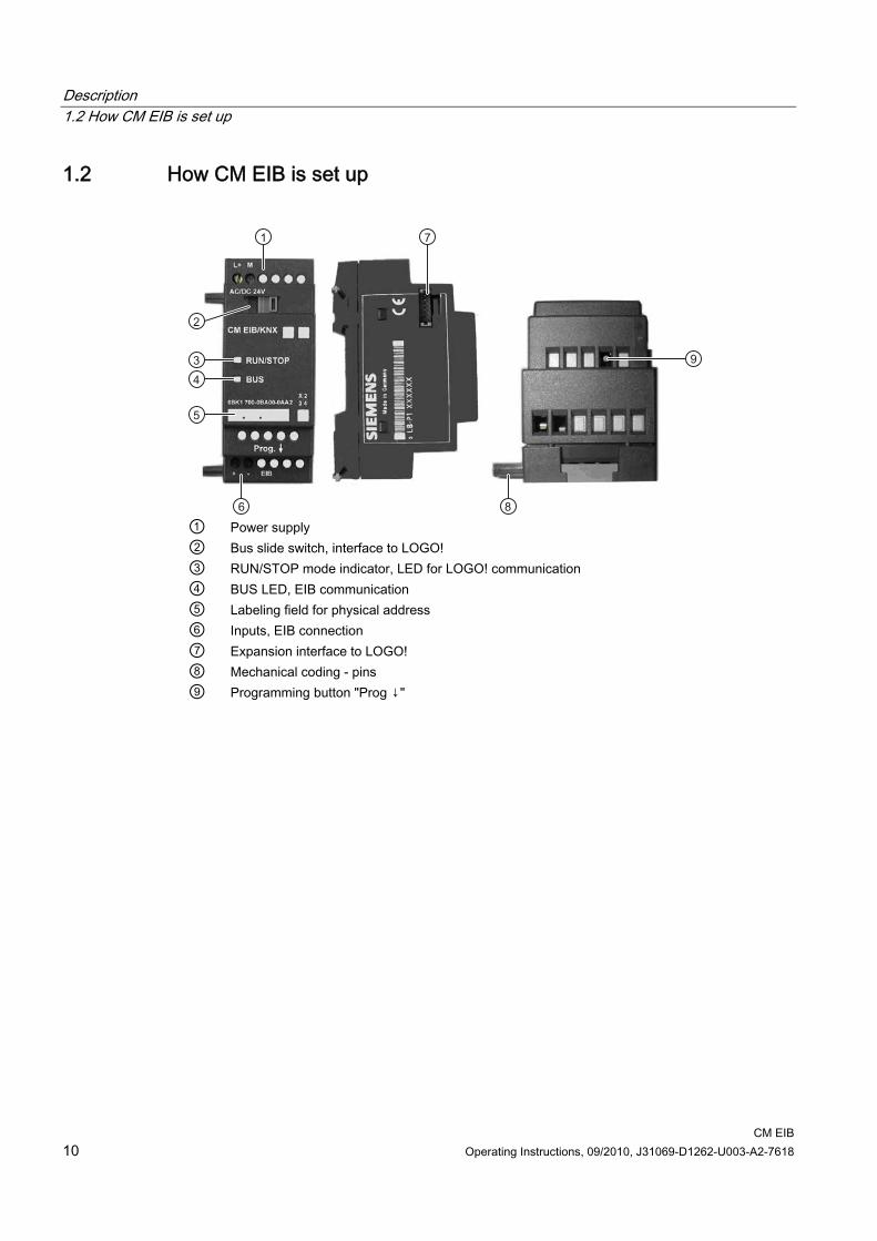
1.2 How CM EIB is set up
① Power supply ② Bus slide switch, interface to LOGO! ③ RUN/STOP mode indicator, LED for LOGO! communication ④ BUS LED, EIB communication ⑤ Labeling field for physical address ⑥ Inputs, EIB connection ⑦ Expansion interface to LOGO! ⑧ Mechanical coding - pins ⑨ Programming button "Prog ↓"

CM EIB Operating Instructions, 09/2010, J31069-D1262-U003-A2-7618 11
Application planning 22.1 General installation guidelines
General installation guidelines The following guidelines must be observed when mounting and connecting the CM EIB: ● When connecting the CM EIB, make sure that you observe all applicable and legally
binding standards. Adhere to the relevant national and regional regulations when installing and operating the device. Check with the local authorities regarding the standards and rules to be followed in your particular case.
● Ensure a zero-voltage state during assembly and connection work. ● Use only approved bus cables (see Chapter Technical data (Page 43)). ● The EIB bus cable can also be routed in parallel with other cables. ● CM EIB must always be installed as the last module to the right of LOGO!, because no
additional interface modules may be connected to the CM EIB. ● Separate power supply for LOGO! and EIB.
WARNING
Removal and insertion of the expansion modules may take place only in a zero-voltage state.
2.2 Transportation The devices must be transported in a clean and dry state, preferably in their original packaging. The transport temperature must be between - 40 °C and + 70 °C. Temperature fluctuations greater than 20 K per hour are not permitted.
2.3 Storage The devices must be stored in clean and dry rooms, preferably in their original packaging. The storage temperature must be between - 40 °C and + 55 °C. Temperature fluctuations greater than 20 °C per hour are not permitted.

Application planning 2.3 Storage
CM EIB 12 Operating Instructions, 09/2010, J31069-D1262-U003-A2-7618

CM EIB Operating Instructions, 09/2010, J31069-D1262-U003-A2-7618 13
Installation 33.1 Installation
Requirements ● Create a zero-voltage state. ● CM EIB must always be installed as the last module to the right of LOGO!, because no
additional interface modules may be connected to the CM EIB.
Installation instructions 1. Follow the installation instructions included with every device. 2. Also follow the assembly and disassembly instructions in the LOGO! manual.
WARNING
Removal and insertion of the expansion modules may take place only in a zero-voltage state.

Installation 3.1 Installation
CM EIB 14 Operating Instructions, 09/2010, J31069-D1262-U003-A2-7618

CM EIB Operating Instructions, 09/2010, J31069-D1262-U003-A2-7618 15
Connecting 44.1 Connecting the power supply
The CM EIB can be powered with a choice of 24 V AC or 24 V DC. The CM EIB is a switching device with protective insulation. A protective conductor connection is not required.
Note Refer to the connection notes in the included product documentation Refer to the connection notes in the product information included with your device as well as the technical data regarding the allowable voltage tolerances, line frequencies, and power consumption.
Requirements ● The device is installed properly. ● Disconnected from supply ● Tool to be used: Screwdriver with 3 mm blade width
(the LOGO! and EIB/KNX terminals are identical.)
Connecting 4.1 Connecting the power supply
CM EIB 16 Operating Instructions, 09/2010, J31069-D1262-U003-A2-7618
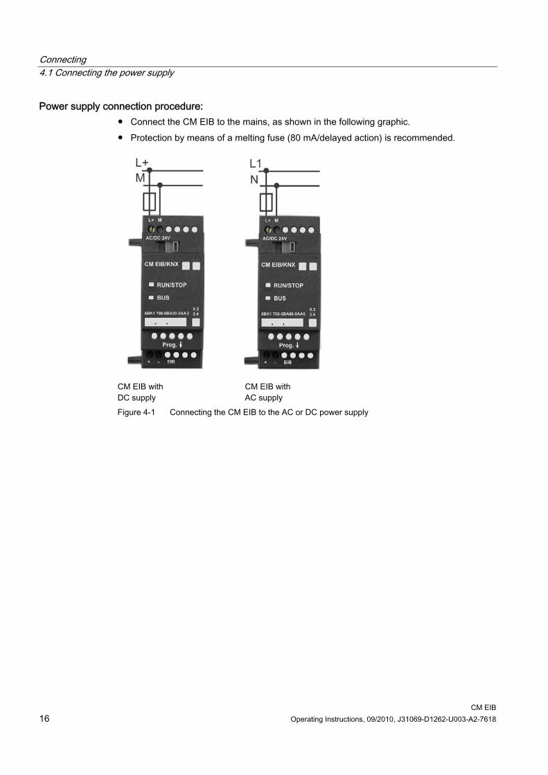
Power supply connection procedure: ● Connect the CM EIB to the mains, as shown in the following graphic. ● Protection by means of a melting fuse (80 mA/delayed action) is recommended.
CM EIB with DC supply
CM EIB with AC supply
Figure 4-1 Connecting the CM EIB to the AC or DC power supply
Connecting 4.2 Connecting the EIB
CM EIB Operating Instructions, 09/2010, J31069-D1262-U003-A2-7618 17
4.2 Connecting the EIB
Material and tools to be used ● Standard bus cable (see Chapter Technical data (Page 43)). ● Screwdriver with 3 mm blade width
(the LOGO! and EIB/KNX terminals are identical.)
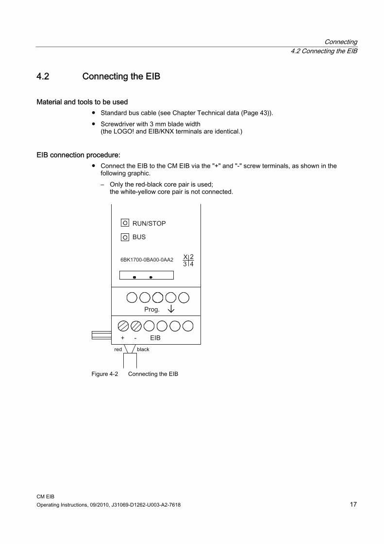
EIB connection procedure: ● Connect the EIB to the CM EIB via the "+" and "-" screw terminals, as shown in the
following graphic. – Only the red-black core pair is used;
the white-yellow core pair is not connected.
Figure 4-2 Connecting the EIB

Connecting 4.2 Connecting the EIB
CM EIB 18 Operating Instructions, 09/2010, J31069-D1262-U003-A2-7618

CM EIB Operating Instructions, 09/2010, J31069-D1262-U003-A2-7618 19
Commissioning 55.1 Commissioning steps
Prerequisite ● BUS and power supply must be present.
Procedure 1. Connect the PC via the serial EIB interface. 2. Start ETS. 3. Configuration of the application program in the ETS. 4. The application program is loaded via the EIB interface in the nodes. The application
program is available on the LOGO! homepage (http://www.siemens.com/logo). 5. Click "Program Physical Address" in the ETS. 6. Press the "Prog ↓" button on the CM EIB to switch the CM EIB to programming mode.
The "BUS" LED glows orange.
NOTICE
The "Prog ↓" button must not be pressed too hard. This could damage the device. If a contact is present, the LED glows orange.
7. The LED stops glowing when programming of the physical address is complete. You can now indicate the physical address on the unit. Composition of physical address:
Area / Line / Node XX XX XXX 1. You can now install the application program.
The device is then ready for operation. 2. If several CM EIB are installed in an EIB system, steps 1-9 must be repeated for each CM
EIB.
Note Please refer to the corresponding EIB/KNX documentation for further details regarding EIB installation.

Commissioning 5.2 Operating states of the CM EIB
CM EIB 20 Operating Instructions, 09/2010, J31069-D1262-U003-A2-7618
5.2 Operating states of the CM EIB The CM EIB is a LOGO! expansion module and has two LEDs that indicate the operating state of the device. These are: ● "RUN/STOP" LED: Communication with LOGO! ● "BUS" LED: EIB status
Figure 5-1 CM EIB with the LEDs for indicating the operating state
The "RUN/STOP" LED can glow green, red, or orange and indicates the following operating states:
RUN/STOP LED glows Green (RUN) Red (STOP) Orange
The expansion module is communicating with the device
on the left
The expansion module is not communicating with the device
on the left
Initialization phase of the expansion module
The "BUS" LED can glow green, red, or orange and indicates the following operating states:
BUS LED glows Green Red Orange
Bus connection OK, communication OK, no
programming mode
Bus connection fault Programming mode is active and bus connection is OK

Commissioning 5.3 Response to communications failure
CM EIB Operating Instructions, 09/2010, J31069-D1262-U003-A2-7618 21
5.3 Response to communications failure
LOGO! power failure In the event of LOGO! power failure or interruption of communication to the LOGO! master or the left communication partner, the outputs are set to 0. The RUN/STOP LED glows red after one second.
Power restoration to LOGO! LOGO! restarts, CM sends the parameterized states.
CM power failure All inputs of the LOGO! master on the EIB are set to 0 by the LOGO! master.
Power restoration to CM All inputs of the LOGO! master on the EIB are updated. Depending on the parameterization, the inputs are read by the EIB.
Short-circuit or interruption of BUS The last value received at inputs and outputs is retained until a new value is received. After 5 seconds, the red LED lights up.
BUS restored When the BUS returns, the CM behaves neutrally, i.e. it does not send any message frames.

Commissioning 5.3 Response to communications failure
CM EIB 22 Operating Instructions, 09/2010, J31069-D1262-U003-A2-7618

CM EIB Operating Instructions, 09/2010, J31069-D1262-U003-A2-7618 23
Service and maintenance 66.1 Service and maintenance
The device is designed for maintenance-free operation. ● Still clean the surfaces at regular intervals. ● Also, remove dirt from the housing to avoid impairing the function of the operator controls
and the enclosure ventilation.
6.2 Repair For questions related to the repair process, please contact the relevant Siemens regional office.
6.3 Disposal Devices described in this programming manual can be recycled owing to the low content of noxious substances in their version. Please contact a certified waste disposal company for eco-friendly recycling and to dispose of your old devices.

Service and maintenance 6.3 Disposal
CM EIB 24 Operating Instructions, 09/2010, J31069-D1262-U003-A2-7618
CM EIB Operating Instructions, 09/2010, J31069-D1262-U003-A2-7618 25
Functions 77.1 Available functions
The CM EIB takes over communication between LOGO! and EIB and enables communication via EIB inputs and outputs.
7.2 Communication with the LOGO! master
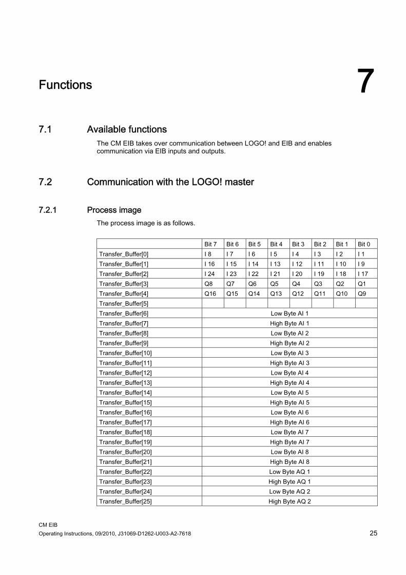
7.2.1 Process image The process image is as follows. Bit 7 Bit 6 Bit 5 Bit 4 Bit 3 Bit 2 Bit 1 Bit 0 Transfer_Buffer[0] I 8 I 7 I 6 I 5 I 4 I 3 I 2 I 1 Transfer_Buffer[1] I 16 I 15 I 14 I 13 I 12 I 11 I 10 I 9 Transfer_Buffer[2] I 24 I 23 I 22 I 21 I 20 I 19 I 18 I 17 Transfer_Buffer[3] Q8 Q7 Q6 Q5 Q4 Q3 Q2 Q1 Transfer_Buffer[4] Q16 Q15 Q14 Q13 Q12 Q11 Q10 Q9 Transfer_Buffer[5] Transfer_Buffer[6] Low Byte AI 1 Transfer_Buffer[7] High Byte AI 1 Transfer_Buffer[8] Low Byte AI 2 Transfer_Buffer[9] High Byte AI 2 Transfer_Buffer[10] Low Byte AI 3 Transfer_Buffer[11] High Byte AI 3 Transfer_Buffer[12] Low Byte AI 4 Transfer_Buffer[13] High Byte AI 4 Transfer_Buffer[14] Low Byte AI 5 Transfer_Buffer[15] High Byte AI 5 Transfer_Buffer[16] Low Byte AI 6 Transfer_Buffer[17] High Byte AI 6 Transfer_Buffer[18] Low Byte AI 7 Transfer_Buffer[19] High Byte AI 7 Transfer_Buffer[20] Low Byte AI 8 Transfer_Buffer[21] High Byte AI 8 Transfer_Buffer[22] Low Byte AQ 1 Transfer_Buffer[23] High Byte AQ 1 Transfer_Buffer[24] Low Byte AQ 2 Transfer_Buffer[25] High Byte AQ 2

Functions 7.2 Communication with the LOGO! master
CM EIB 26 Operating Instructions, 09/2010, J31069-D1262-U003-A2-7618
7.2.2 Data telegram: Time The LOGO! master supports the exchange of date and time in both directions. Ensure that on the LOGO! master "On" is set in the Clock/Sync menu if the time is to be synchronized from the EIB. If the LOGO! master is also the time master, it will send a time message frame to the CM EIB every hour or in the event of a change. The CM EIB forwards the time message frame directly to the EIB. Because the CM EIB does not have a real-time clock of its own, the time cannot be read on the bus side.
Functions 7.3 EIB inputs/outputs
CM EIB Operating Instructions, 09/2010, J31069-D1262-U003-A2-7618 27
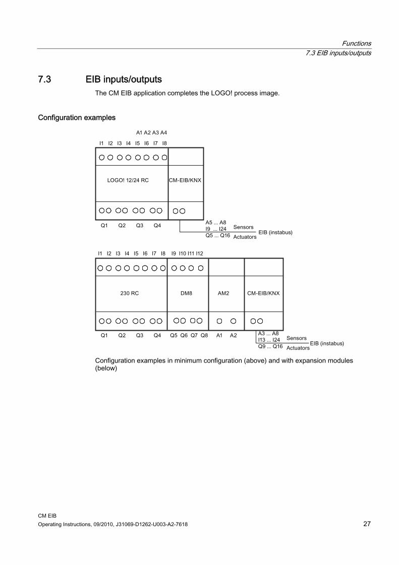
7.3 EIB inputs/outputs The CM EIB application completes the LOGO! process image.
Configuration examples
Configuration examples in minimum configuration (above) and with expansion modules (below)
Functions 7.3 EIB inputs/outputs
CM EIB 28 Operating Instructions, 09/2010, J31069-D1262-U003-A2-7618
Application example
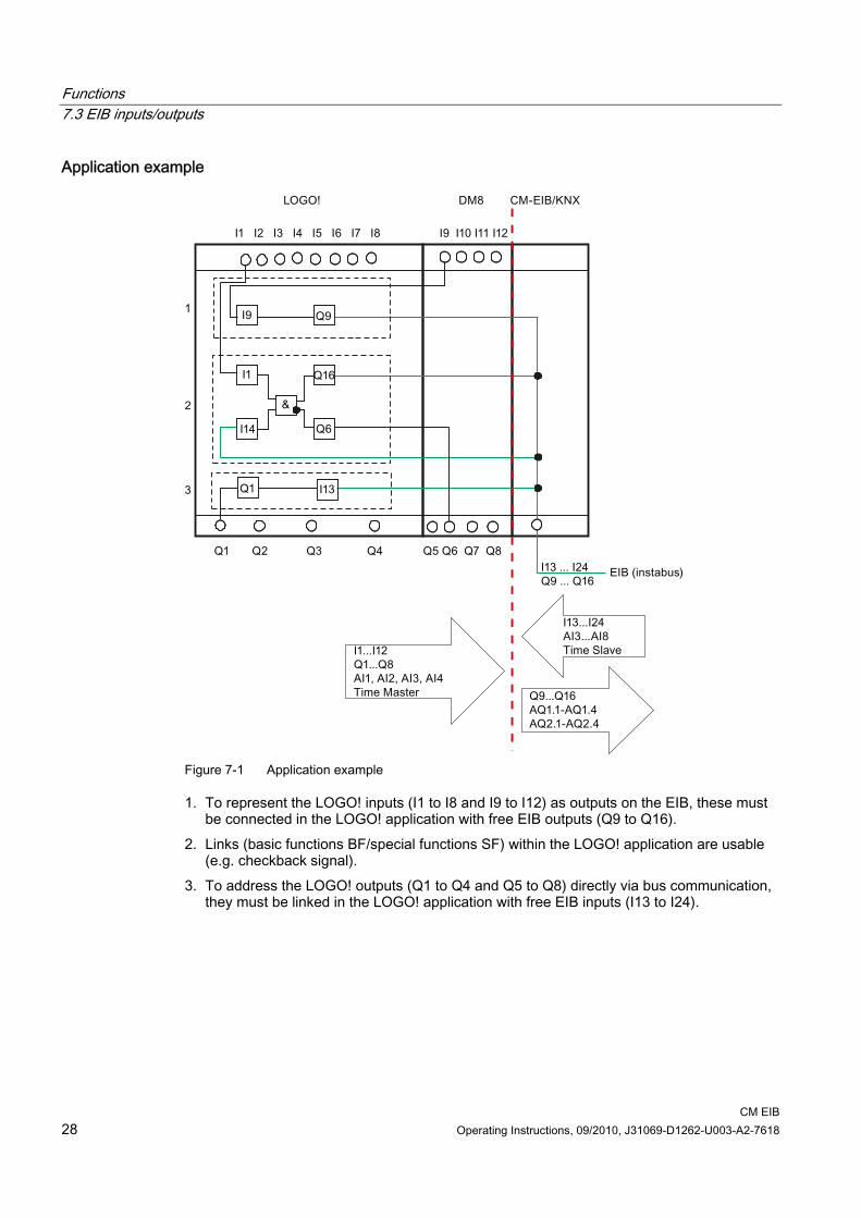
Figure 7-1 Application example
1. To represent the LOGO! inputs (I1 to I8 and I9 to I12) as outputs on the EIB, these must be connected in the LOGO! application with free EIB outputs (Q9 to Q16).
2. Links (basic functions BF/special functions SF) within the LOGO! application are usable (e.g. checkback signal).
3. To address the LOGO! outputs (Q1 to Q4 and Q5 to Q8) directly via bus communication, they must be linked in the LOGO! application with free EIB inputs (I13 to I24).

Functions 7.4 EIB communication
CM EIB Operating Instructions, 09/2010, J31069-D1262-U003-A2-7618 29
7.4 EIB communication The LOGO! hardware inputs and outputs are also represented on the EIB.
7.4.1 EIB communication objects
7.4.1.1 LOGO! digital inputs LOGO! input Available on LOGO
HW Communication object Parameter
I1 X Digital output I1 - I2 X Digital output I2 - I3 X Digital output I3 - I4 X Digital output I4 - I5 X Digital output I5 - I6 X Digital output I6 - I7 X Digital output I7 - I8 X Digital output I8 - I9 X Digital output I9 - I9 Digital input I9 Monoflop (time), preferred state I10 X Digital output I10 - I10 Digital input I10 Monoflop (time), preferred state I11 X Digital output I11 - I11 Digital input I11 Monoflop (time), preferred state I12 X Digital output I12 - I12 Digital input I12 Monoflop (time), preferred state I13 X Digital output I13 - I13 Digital input I13 Monoflop (time), preferred state I14 X Digital output I14 - I14 Digital input I14 Monoflop (time), preferred state I15 X Digital output I15 - I15 Digital input I15 Monoflop (time), preferred state I16 X Digital output I16 - I16 Digital input I16 Monoflop (time), preferred state I17 X Digital output I17 - I17 Digital input I17 Monoflop (time), preferred state I18 X Digital output I18 - I18 Digital input I18 Monoflop (time), preferred state I19 X Digital output I19 - I19 Digital input I19 Monoflop (time), preferred state I20 X Digital output I20 - I20 Digital input I20 Monoflop (time), preferred state
Functions 7.4 EIB communication
CM EIB 30 Operating Instructions, 09/2010, J31069-D1262-U003-A2-7618
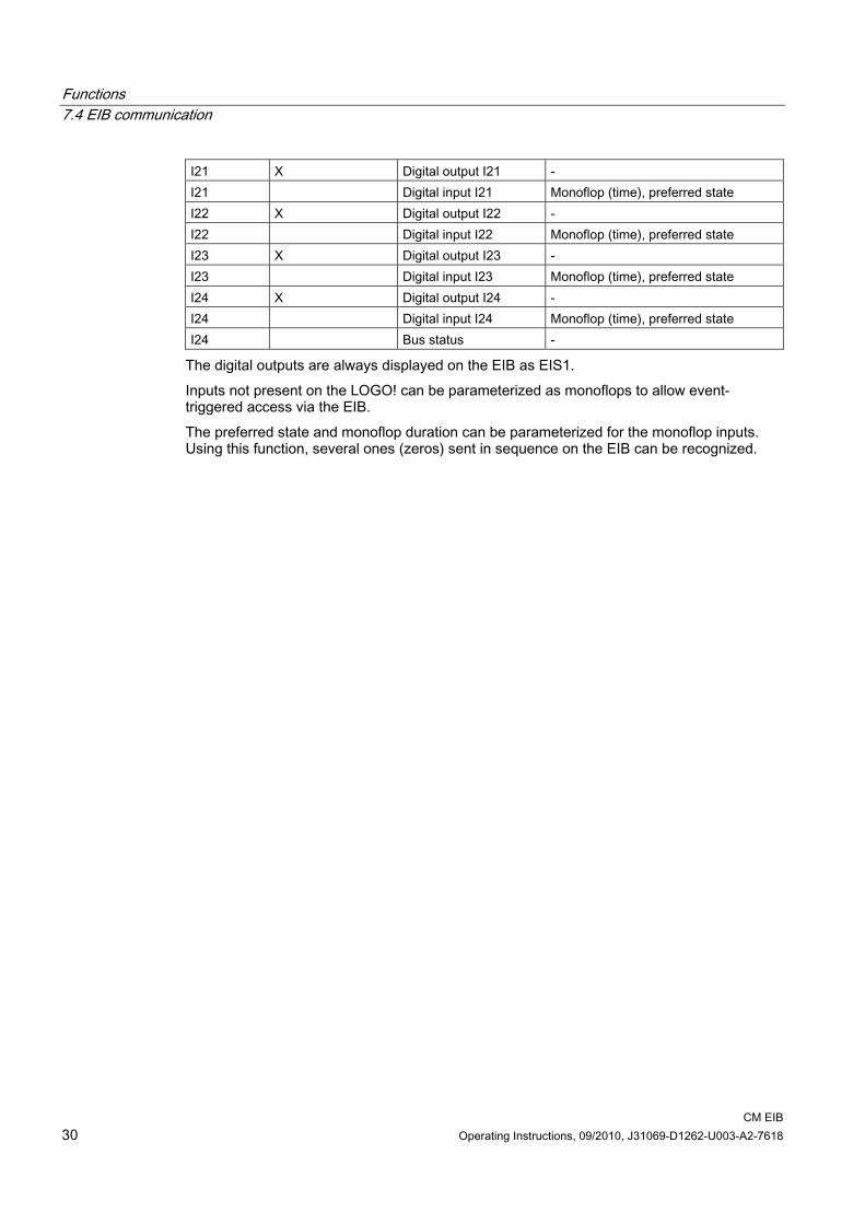
I21 X Digital output I21 - I21 Digital input I21 Monoflop (time), preferred state I22 X Digital output I22 - I22 Digital input I22 Monoflop (time), preferred state I23 X Digital output I23 - I23 Digital input I23 Monoflop (time), preferred state I24 X Digital output I24 - I24 Digital input I24 Monoflop (time), preferred state I24 Bus status -
The digital outputs are always displayed on the EIB as EIS1. Inputs not present on the LOGO! can be parameterized as monoflops to allow event-triggered access via the EIB. The preferred state and monoflop duration can be parameterized for the monoflop inputs. Using this function, several ones (zeros) sent in sequence on the EIB can be recognized.
Functions 7.4 EIB communication
CM EIB Operating Instructions, 09/2010, J31069-D1262-U003-A2-7618 31
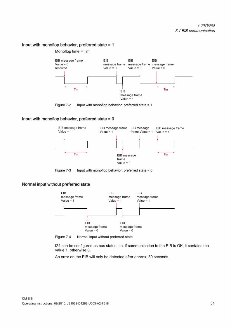
Input with monoflop behavior, preferred state = 1 Monoflop time = Tm
Figure 7-2 Input with monoflop behavior, preferred state = 1
Input with monoflop behavior, preferred state = 0
Figure 7-3 Input with monoflop behavior, preferred state = 0
Normal input without preferred state
Figure 7-4 Normal input without preferred state
I24 can be configured as bus status, i.e. if communication to the EIB is OK, it contains the value 1, otherwise 0. An error on the EIB will only be detected after approx. 30 seconds.

Functions 7.4 EIB communication
CM EIB 32 Operating Instructions, 09/2010, J31069-D1262-U003-A2-7618
7.4.1.2 LOGO! digital outputs LOGO! output
Available on LOGO HW
Communication object Parameter
Q1 X Digital output Q1 - Q2 X Digital output Q2 - Q3 X Digital output Q3 - Q4 X Digital output Q4 - Q5 X Digital output Q5 - Q5 Digital output Q5 Dimmer/step code/edge Q6 X Digital output Q6 - Q6 Digital output Q6 Dimmer/step code/edge Q7 X Digital output Q7 - Q7 Digital output Q7 Dimmer/step code/edge Q8 X Digital output Q8 - Q8 Digital output Q8 Dimmer/step code/edge Q9 X Digital output Q9 - Q9 Digital output Q9 Dimmer/step code/edge Q10 X Digital output Q10 - Q10 Digital output Q10 Dimmer/step code/edge Q11 X Digital output Q11 - Q11 Digital output Q11 Dimmer/step code/edge Q12 X Digital output Q12 - Q12 Digital output Q12 Dimmer/step code/edge Q13 X Digital output Q13 - Q13 Digital output Q13 Dimmer/step code/edge Q14 X Digital output Q14 - Q14 Digital output Q14 Dimmer/step code/edge Q15 X Digital output Q15 - Q15 Digital output Q15 Dimmer/step code/edge Q16 X Digital output Q16 - Q16 Digital output Q16 Dimmer/step code/edge
The digital outputs not on the LOGO! hardware can be parameterized either as dimmers or edge evaluation (for control of blinds). For the configuration as dimmer, 2 LOGO! outputs are combined for each dimmer output (Q5/6, Q7/8, Q9/10, Q11/12, Q13/14, Q15/16). The first digital output corresponds to brighter and the second one corresponds to darker. The dimming speed is set as a parameter in the EIB configuration.

Functions 7.4 EIB communication
CM EIB Operating Instructions, 09/2010, J31069-D1262-U003-A2-7618 33
Figure 7-5 EIB dimming control
If 2 outputs are parameterized as shutter/blind controllers (0/1 suppression and edge evaluation), one output each is parameterized as 0 suppression (only falling edges are sent as 0 on the EIB) and one output is parameterized as 1 suppression (only rising edges are sent as 1 on the EIB). Using this function, several message frames can be sent sequentially on the EIB with a 1 (or 0). The outputs Q13/14 and Q15/16 (if not available in the LOGO! hardware) can be configured as multiplexers for the analog outputs. To do this, the inputs of the analog multiplexer must be linked in parallel to the outputs in the LOGO! application.
Functions 7.4 EIB communication
CM EIB 34 Operating Instructions, 09/2010, J31069-D1262-U003-A2-7618
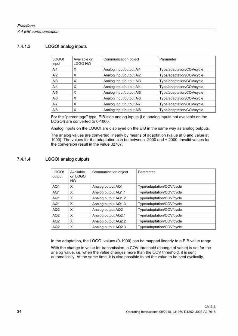
7.4.1.3 LOGO! analog inputs LOGO! input
Available on LOGO HW
Communication object Parameter
Ai1 X Analog input/output Ai1 Type/adaptation/COV/cycle Ai2 X Analog input/output Ai2 Type/adaptation/COV/cycle Ai3 X Analog input/output Ai3 Type/adaptation/COV/cycle Ai4 X Analog input/output Ai4 Type/adaptation/COV/cycle Ai5 X Analog input/output Ai5 Type/adaptation/COV/cycle Ai6 X Analog input/output Ai6 Type/adaptation/COV/cycle Ai7 X Analog input/output Ai7 Type/adaptation/COV/cycle Ai8 X Analog input/output Ai8 Type/adaptation/COV/cycle
For the "percentage" type, EIB-side analog inputs (i.e. analog inputs not available on the LOGO!) are converted to 0-1000. Analog inputs on the LOGO! are displayed on the EIB in the same way as analog outputs. The analog values are converted linearly by means of adaptation (value at 0 and value at 1000). The values for the adaptation can be between -2000 and + 2000. Invalid values for the conversion result in the value 32767.
7.4.1.4 LOGO! analog outputs LOGO! output
Available on LOGO HW
Communication object Parameter
AQ1 X Analog output AQ1 Type/adaptation/COV/cycle AQ1 X Analog output AQ1.1 Type/adaptation/COV/cycle AQ1 X Analog output AQ1.2 Type/adaptation/COV/cycle AQ1 X Analog output AQ1.3 Type/adaptation/COV/cycle AQ2 X Analog output AQ2 Type/adaptation/COV/cycle AQ2 X Analog output AQ2.1 Type/adaptation/COV/cycle AQ2 X Analog output AQ2.2 Type/adaptation/COV/cycle AQ2 X Analog output AQ2.3 Type/adaptation/COV/cycle
In the adaptation, the LOGO! values (0-1000) can be mapped linearly to a EIB value range. With the change in value for transmission, a COV threshold (change of value) is set for the analog value, i.e. when the value changes more than the COV threshold, it is sent automatically. At the same time, it is also possible to set the value to be sent cyclically.
Functions 7.4 EIB communication
CM EIB Operating Instructions, 09/2010, J31069-D1262-U003-A2-7618 35
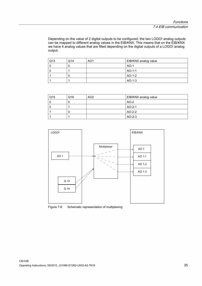
Depending on the value of 2 digital outputs to be configured, the two LOGO! analog outputs can be mapped to different analog values in the EIB/KNX. This means that on the EIB/KNX we have 4 analog values that are filled depending on the digital outputs of a LOGO! analog output. Q13 Q14 AO1 EIB/KNX analog value 0 0 AO-1 0 1 AO-1-1 1 0 AO-1-2 1 1 AO-1-3
Q15 Q16 AO2 EIB/KNX analog value 0 0 AO-2 0 1 AO-2-1 1 0 AO-2-2 1 1 AO-2-3
Figure 7-6 Schematic representation of multiplexing

Functions 7.4 EIB communication
CM EIB 36 Operating Instructions, 09/2010, J31069-D1262-U003-A2-7618
7.4.2 EIB parameterization
7.4.2.1 LOGO! configuration The dialog screen shown below is used to change LOGO! configuration settings.
Figure 7-7 LOGO! configuration
Configuration parameters The individual configuration parameters are described below: ● Number of digital inputs/outputs, locally on the LOGO! and virtually via EIB
The parameters for the digital EIB inputs/outputs are shown or hidden depending on this information.
● Number of analog values, locally on the LOGO! and virtually via EIB The parameters for the analog EIB inputs/outputs are shown or hidden depending on this information.
● Time and date Here, the functionality can be set to time master (primary), time slave (secondary), or inactive.
Functions 7.4 EIB communication
CM EIB Operating Instructions, 09/2010, J31069-D1262-U003-A2-7618 37
● Time and date data type 2 data types can be chosen here: 3 bytes each for time and date or 8 bytes combined data type for date and time.
● Response to bus power failure If bus power is lost, the EIB inputs are retained or set to 0, depending on the settings.
● Response to return of bus power In accordance with these settings, the EIB outputs are sent even if the values are = 0 when bus power returns to the EIB.
● Input I24 function I24 serves either as a normal input or as bus status.
Special features of inputs/outputs In order to use the LOGO! inputs/outputs on CM EIB, the following must be observed: To address the LOGO! outputs (Q1 to Q4) directly via bus communication, they must be linked in the LOGO! application with free EIB inputs. To represent the LOGO! inputs (I1 to I8) as outputs on the bus, these must be linked with free EIB outputs in the LOGO! application.
Functions 7.4 EIB communication
CM EIB 38 Operating Instructions, 09/2010, J31069-D1262-U003-A2-7618
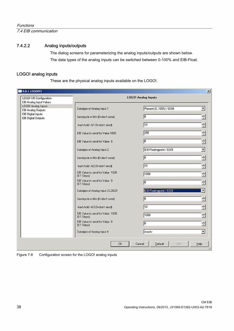
7.4.2.2 Analog inputs/outputs The dialog screens for parameterizing the analog inputs/outputs are shown below. The data types of the analog inputs can be switched between 0-100% and EIB-Float.
LOGO! analog inputs These are the physical analog inputs available on the LOGO!.
Figure 7-8 Configuration screen for the LOGO! analog inputs

Functions 7.4 EIB communication
CM EIB Operating Instructions, 09/2010, J31069-D1262-U003-A2-7618 39
EIB analog inputs These are the logical analog inputs on the EIB module.
Figure 7-9 Configuration screen for the EIB analog inputs
Functions 7.4 EIB communication
CM EIB 40 Operating Instructions, 09/2010, J31069-D1262-U003-A2-7618
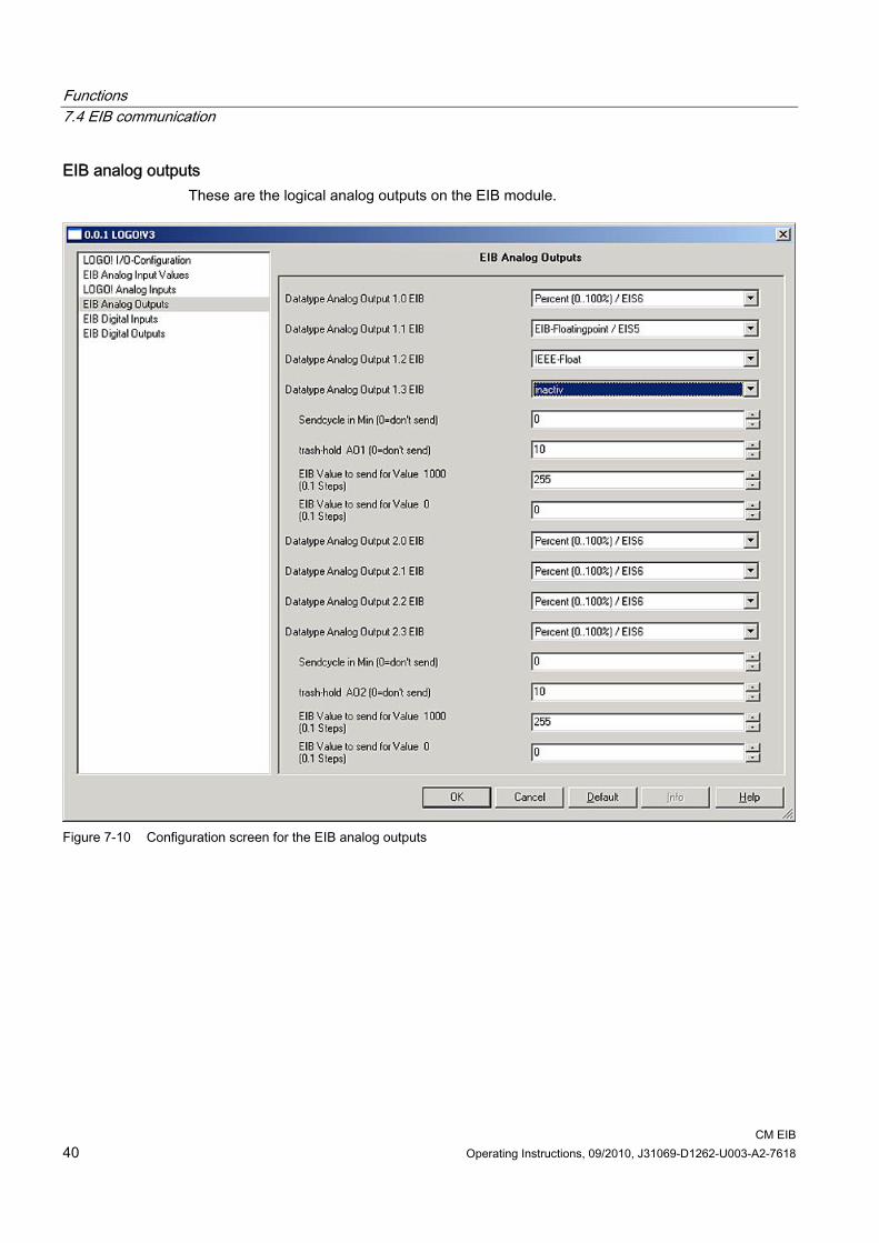
EIB analog outputs These are the logical analog outputs on the EIB module.
Figure 7-10 Configuration screen for the EIB analog outputs
Functions 7.4 EIB communication
CM EIB Operating Instructions, 09/2010, J31069-D1262-U003-A2-7618 41
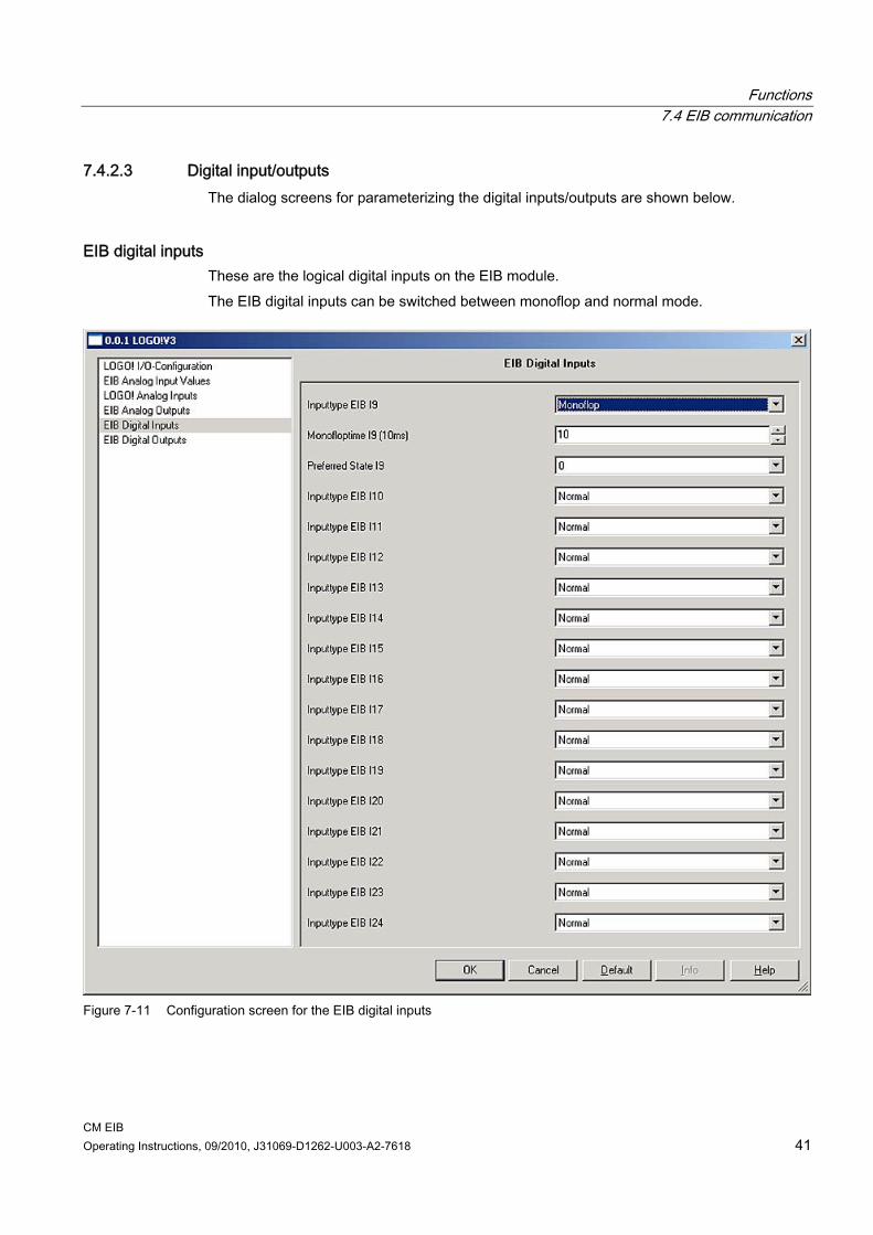
7.4.2.3 Digital input/outputs The dialog screens for parameterizing the digital inputs/outputs are shown below.
EIB digital inputs These are the logical digital inputs on the EIB module. The EIB digital inputs can be switched between monoflop and normal mode.
Figure 7-11 Configuration screen for the EIB digital inputs
Functions 7.4 EIB communication
CM EIB 42 Operating Instructions, 09/2010, J31069-D1262-U003-A2-7618
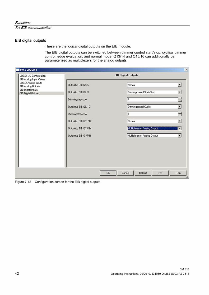
EIB digital outputs These are the logical digital outputs on the EIB module. The EIB digital outputs can be switched between dimmer control start/stop, cyclical dimmer control, edge evaluation, and normal mode. Q13/14 and Q15/16 can additionally be parameterized as multiplexers for the analog outputs.
Figure 7-12 Configuration screen for the EIB digital outputs
CM EIB Operating Instructions, 09/2010, J31069-D1262-U003-A2-7618 43
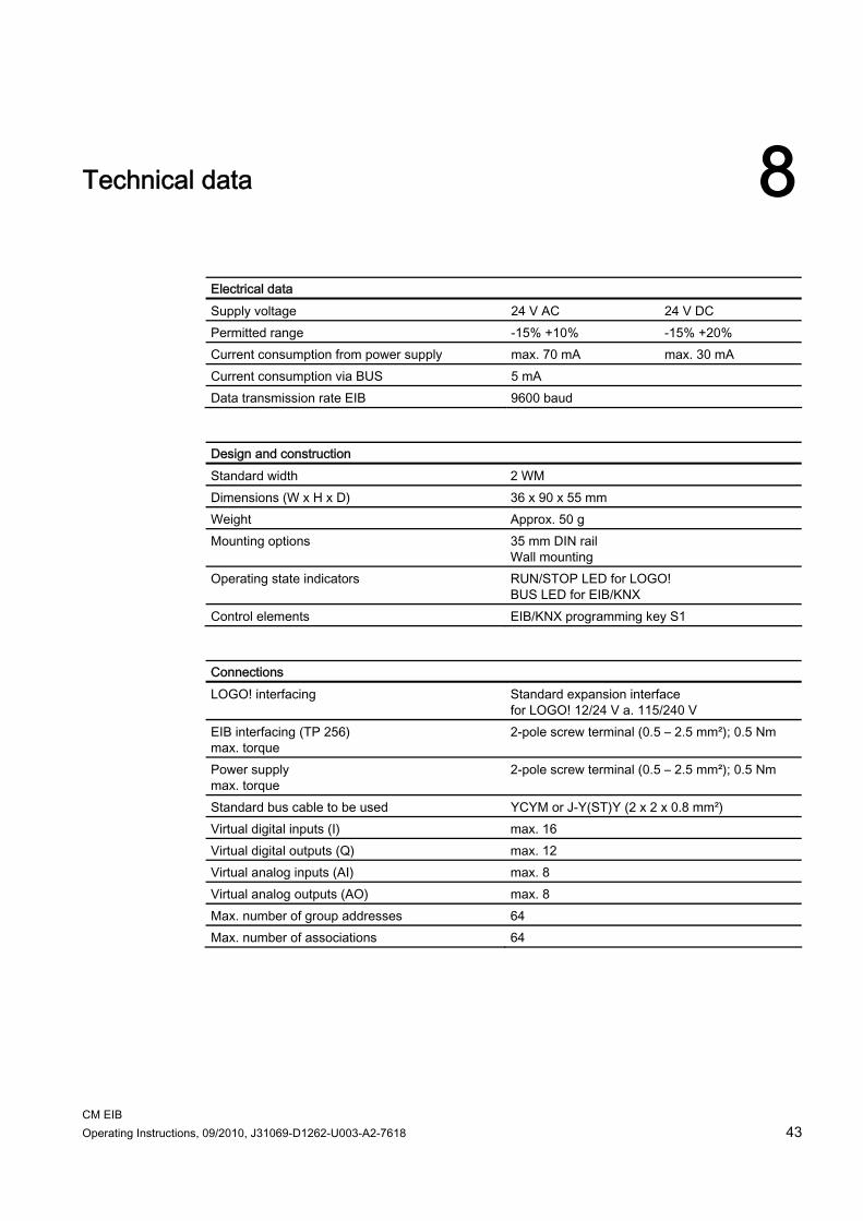
Technical data 8
Electrical data Supply voltage 24 V AC 24 V DC Permitted range -15% +10% -15% +20% Current consumption from power supply max. 70 mA max. 30 mA Current consumption via BUS 5 mA Data transmission rate EIB 9600 baud
Design and construction Standard width 2 WM Dimensions (W x H x D) 36 x 90 x 55 mm Weight Approx. 50 g Mounting options 35 mm DIN rail
Wall mounting Operating state indicators RUN/STOP LED for LOGO!
BUS LED for EIB/KNX Control elements EIB/KNX programming key S1
Connections LOGO! interfacing Standard expansion interface
for LOGO! 12/24 V a. 115/240 V EIB interfacing (TP 256) max. torque
2-pole screw terminal (0.5 – 2.5 mm²); 0.5 Nm
Power supply max. torque
2-pole screw terminal (0.5 – 2.5 mm²); 0.5 Nm
Standard bus cable to be used YCYM or J-Y(ST)Y (2 x 2 x 0.8 mm²) Virtual digital inputs (I) max. 16 Virtual digital outputs (Q) max. 12 Virtual analog inputs (AI) max. 8 Virtual analog outputs (AO) max. 8 Max. number of group addresses 64 Max. number of associations 64

Technical data
CM EIB 44 Operating Instructions, 09/2010, J31069-D1262-U003-A2-7618
Ambient conditions Permissible operating temperature 0 °C to +55 °C
Natural convection Storage and transport temperature -40 °C to +70 °C Humidity 95% at +25 °C
Safety Degree of protection IP 20 Radio interference suppression EN 55011 (limit class B) Certification CE
EIB/KNX UL 508 VDE 0631 IEC 61131-2
Overvoltage protection: Fuse
80 mA slow-action
Ordering data LOGO! interface module EIB/KNX CM 6BK1700-0BA00-0AA2

CM EIB Operating Instructions, 09/2010, J31069-D1262-U003-A2-7618 45
List of abbreviations A
CM Communication module EIB European Installation Bus EIS EIB Interoperability Standard ETS EIB Tool Software KNX Standard of the Konnex Association

List of abbreviations
CM EIB 46 Operating Instructions, 09/2010, J31069-D1262-U003-A2-7618


Order no. J31069-D1262-U003-A2
Siemens AktiengesellschaftIndustry AutomationControl Components and Systems EngineeringPO. 2355, D-90713 FürthDEUTSCHLANDwww.siemens.com
Order No. J31069-D1262-U003-A2-7618
Siemens AGIndustry AutomationControl Components and Systems EngineeringPO. 2355, D-90713 FürthGERMANY