Clipsal Integrated Systems
88
clipsal.com/cis clipsal.com/cis Redefining the boundaries of technology
-
Upload
sabrejaguar -
Category
Documents
-
view
1.640 -
download
25
Transcript of Clipsal Integrated Systems

clipsal.com/cisclipsal.com/cis
Red
efin
ing
th
e b
ou
nd
ari
es o
f te
chn
olo
gy
C-Bus® Product Overview OvOOOOOOvv
Clipsal® Australia fi rst started from humble beginnings in 1920, with a range of adjustable conduit fi ttings that ‘clips all’ sizes of conduit, thus the name Clipsal® was born. More than 85 years on, Clipsal® has become one of the leading producers of electrical products in its fi eld.
As a company and brand, Clipsal® has continuously developed and evolved to meet the needs of commercial and domestic requirements. Development in automation products led to the formation of CIS (Clipsal® Integrated Systems) in 2000, a business unit of Clipsal® Australia specialising in the manufacture of electronic lighting and building automation products. Since then CIS has grown rapidly, gaining widespread acceptance in major commercial and domestic markets. Today CIS employs more than 250 personnel.
Through extensive research and design, CIS developed the C-Bus® Energy Management and Control System back in 1994, and since then C-Bus® has become the ‘benchmark’ of CIS’ product range. Initially, C-Bus® was designed and manufactured for commercial application, however, due to increasing worldwide interest, C-Bus® has been adapted to suit the domestic market with the release of C-Bus® DIN Rail Series and other associated products.
With the development of C-Bus® for domestic application, a new generation of products was born including the Scene Master® scene controller, C-Touch™ colour touch screens, Neo® C-Bus® wall switches, and Saturn™ C-Bus® wall switches. When the C-Bus® Neo® range was fi rst launched in 2002, it immediately became the ‘new face’ of Clipsal’s® C-Bus® offering. Neo’s® superb design was one of inspiration, as Clipsal® consulted architects and designers for their input, to create a switch that complimented the beautiful home environment. The Saturn™ Range of switches is also a real ‘head turner’. Manufactured from handcrafted glass with bevelled edges, and apertures cut for its distinctive circular, backlit switches.
The year the Neo® Range was launched it won the Australian Electrical and Electronic Manufacturer’s Association (AEEMA) Award for Excellence in Commercialising Research & Development. In the same year, C-Bus® took on the best of European technology to win the 2002 UK Electrical Product Award in the categoryof Contribution Towards Energy Saving.
This was a signifi cant achievement against other established brands. C-Bus® really proved its worth over competitor’s technology based on proven IP (intellectual property), superior performance, features and customer value.
CIS continue to set new precedents by expanding the C-Bus® Range.Introducing products such as C-Bus® Wireless Technology™, Dynamic Labelling Technology™, Refl ection™ Series, Saturn™ Series and Multi-Room Audio™. Not only is the C-Bus® product range extensive, but it also complies with ISO9001 Accreditation.
Initially, as C-Bus® developed, there was an ongoing concern in relation to ensuring the end-user would get the most out of every CIS product. So to avoid this problem, CIS began running the CIS Installer Program and Installer Approval. If a contractor is interested in C-Bus® installation they can contact their local Clipsal® representative who will arrange for them to attend an introductory course on C-Bus®. To become an Approved Installer, the contractor must prove themselves in the fi eld. A minimum of three installations must be completed on the same CIS product, and two of the jobs are inspected by CIS. Once the installer has satisfi ed the requirements of CIS they are issued witha CIS Approved Installer Card.
In conclusion, CIS are continually striving to meet the demands and requirements of their customers by offering the highest quality energy control and management products available on the market. CIS believe that by achieving this they will remain an innovative force behind the manufacturing of automated electronics.
OverviewClipsal Integrated Systems
O i
2

3
Clipsal C-Bus® Overview
C-Bus® Input Units
Wall Switches
General Input Units
Passive Infra-red Motion Sensors
Infra-red Receivers
Scene Controllers
Touch Screens
C-Bus® Output Units
Dimmers
Infra-red Output Units
Relay Units
C-Bus® System Units and Accessories
C-Bus® Software
Multi-Room Audio System
C-Bus® Wireless Systems
Wall Switches
Plug Adaptors
Remote Control Unit
Wireless Gateway
C-Bus® Schematics
2022
466220022
3
4662022 210021
24224242882844443030303030
343434344440
424888525888
6670
Contents
283
848383
8666

4
C-Bus® Product Overview OvOOOOOOvv
Clipsal C-Bus®
Overview
C-Bus® Network Design Considerations
• Up to 1000m of C-Bus® Cat 5 UTP cable may be connected to a single C-Bus® network
• Up to 100 C-Bus® units may be connected to a single C-Bus® network
• Where more than 1 km and/or 100 standard C-Bus® units are required, two or more networks can be created and linked with C-Bus® Network Bridge and/or C-Bus® Ethernet Interface Units
• Maximum number of networks in one installation is 255 (this limitation does not apply if a C-Bus® Ethernet Interface is utilised, the system size is then limited to IP Adressing only)
• Maximum number of networks connected in series to the local network via Network Bridges is seven (i.e. using six network bridges)
• Each standard C-Bus® unit requires 18mA @ 36Vdc to operate correctly. Some C-Bus® units, e.g. 5500PC require 36mA. Some C-Bus® units, e.g. L5108D1A are self-powering and do not take current from the 36V dc C-Bus® network
• More than one C-Bus® power supply can be connected to a C-Bus® network to provide suffi cient power to the C-Bus® units, the C-Bus® power supplies will share the load evenly. Maximum total power supply allowed is 2,000mA (2A)
• Any combination of power supply units is allowed as long as the total power available is 2,000mA or less
• Each C-Bus® network requires only one network burden. This network burden is software selectable on C-Bus® output units
• Each C-Bus® network requires at least one system clock-generating unit (for data synchronisation)
• C-Bus® power supply units may be connected to different phases
• Individual relay channels may be connected to different phases
• On L5508D1A units the mains supply to the units power supply and the mains supply to the output channels must be on the same phase
• The isolation between the mains supply circuitry and the 36V dc C-Bus® circuitry is greater than 3.5kV. This is achieved using double wound transformers and opto isolators. This means the C-Bus® wiring, connections and circuitry can be considered extra low voltage
• C-Bus® Cat 5 UTP cable has mains rated sheathing which means the C-Bus® cable can be taken inside electrical Distribution Boards, provided segregation requirements of local wiring standards are met.
IntroductionThe Clipsal C-Bus® system is a microprocessor based wiring system to control lighting and other electrical services.
Whether ON/OFF control of a lighting circuit or analogue type control such as dimming electronic fl uorescent ballasts, C-Bus® can be to control and automate virtually any type of electrical load.
To ensure fast and reliable operation, each device has its own in-built microprocessor, which can be individually programmed via ‘point and click’ PC based software, or via ‘Learn Mode’ which doesn’t require a PC.
C-Bus® information is held within individual C-Bus® units rather than one central point. This ensures optimum communications speed and reliability.
Whilst a computer is unnecessary for normal C-Bus® operation, C-Bus® PC based control and management software is available and provides additional fl exibility to clients requiring this type of control.
Clipsal C-Bus® is suitable for a wide range of applications, for example.
Commercial Lighting Control• Fluorescent lighting control for energy cost saving in high
rise buildings• High-bay control in warehouses for energy cost saving• Mood lighting in restaurants and retail outlets• Flexible and integrated control of lighting and Audio Visual
equipments in board rooms• Architectural lighting control for hotel foyers, ballrooms, art
galleries and museums.
Standalone Room Lighting Control• Integrated automation via touch screen user interfaces for
conference rooms and home theatres• Multiple scene / mood setting.
Residential Automation• Home entertainment - Integrated audio visual, lighting control,
and other electrical services• Security - Integrated security, lighting and other
electrical services• Comfort – Dimming, scene setting• Convenience – Multiple point control, central point control
from touch screens, automated time based control, automated ‘Goodbye’ and ‘Welcome Home’ moods.

5verviewvervieweerviewTypical C-Bus® wiring schematics are shown on pages 86-87
Typical C-Bus® Network layout

C-Bus® Input Units®
InpInpI pnn
Wall Switches
6
C-Bus® Product Overview
• Available in Saturn™ and Neo® styles
• Saturn units feature an impact resistant glass fascia
• Saturn units available in square and rectangular series in white, black, cream and mid-brown
• Neo units available in square and rectangular series in Neo grey with brushed aluminium look inner surround
• Rectangular series units incorporate eight buttons for C-Bus® Group/Scene over two pages (four buttons per page)
• Square series units incorporate eight buttons for C-Bus® Group/Scene over three pages
• Page/scroll button
• Each button can be programmed with on, off, toggle, dimmer, timer, scene control and custom functions
• LCD labelling for each button
• Text, sliders and bitmaps can be defi ned and downloaded to the unit via a C-Bus® network.
• Dimmable blue LED on each button
• Nightlight on all buttons or just the bottom button
• 64 x 128 pixel LCD screen
• Dimmable white LED backlighting for the LCD
• Ignore fi rst button press option
• Fallback to page 1 option
• Real time clock display
• Programmed via C-Bus® Toolkit software
• Draws 22mA from the C-Bus® network
• C-Bus® learn enabled.
E5084DL,GFWall switch 4 button, DLT™, white
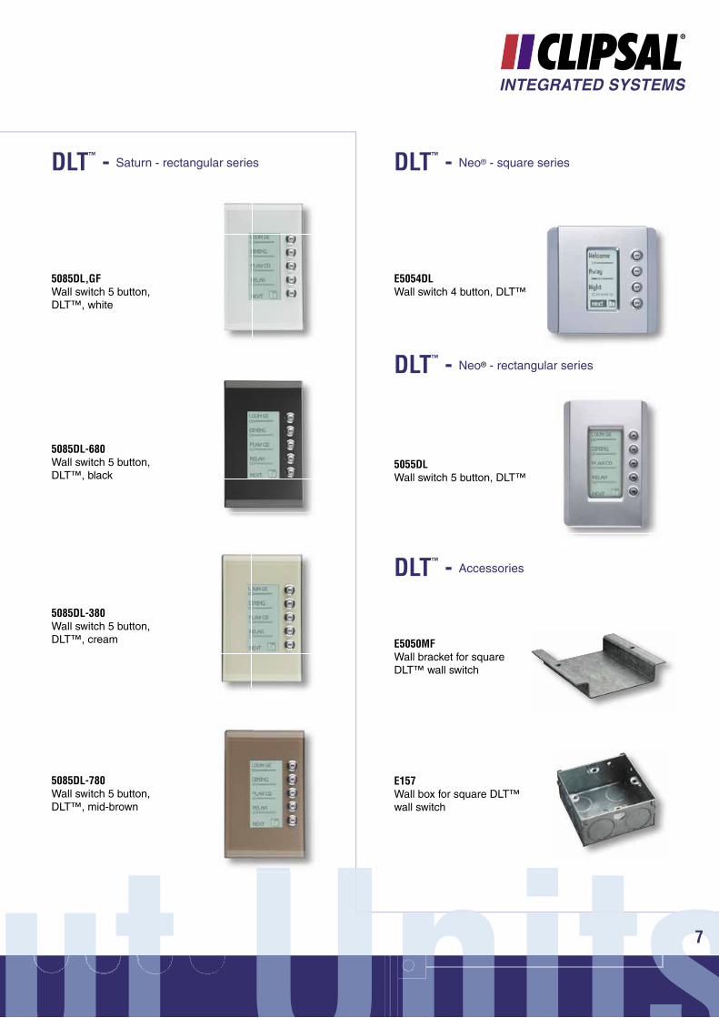
DLT™ - Saturn™ - square series
E5084DL-680Wall switch 4 button, DLT™, black
E5084DL-380Wall switch 4 button, DLT™, cream
E5084DL-780Wall switch 4 button, DLT™, mid-brown
Dynamic Labelling Technology™
ut UnitsUnitsut Unitsnut Unnits7
DLT™ - Saturn - rectangular series
E5054DLWall switch 4 button, DLT™
DLT™ - Neo® - square series
5055DLWall switch 5 button, DLT™
DLT™ - Neo® - rectangular series
E5050MFWall bracket for square DLT™ wall switch
DLT™ - Accessories
5085DL-680Wall switch 5 button, DLT™, black
5085DL-780Wall switch 5 button, DLT™, mid-brown
5085DL-380Wall switch 5 button, DLT™, cream
5085DL,GFWall switch 5 button, DLT™, white
E157Wall box for square DLT™ wall switch

C-Bus® Input Units®
InpInpI pnn
Wall Switches
8
C-Bus® Product Overview
E508xNL,GFWall switch, square, white
E508xNL-680Wall switch, square, black
E508xNL-380Wall switch, square, cream
E508xNL-780Wall switch, square, mid-brown
Saturn™ - square series
• Available in square or rectangular series
• Colours available white, black, cream and mid-brown
• Impact resistant glass fascia
• 2, 4 or 6 buttons per wall switch
• Programmable as on, off, toggle, dimmer, timer, scene control and custom functions
• Selectable blue and orange LED indicator on each button confi gured through C-Bus® Toolkit software
• LED button indicators provide illumination and status feedback
• Nightlight feature
• Fall back level option to dim indicators at a set time after the last button press
• Mounted using standard mounting accessories (ordered separately)
• Programmed via Learn Mode or the C-Bus® Toolkit software
• Draws 22mA from the C-Bus® network
• C-Bus® Learn Enabled.
‘x’ denotes number of buttons i.e. 2, 4 or 6 button
Saturn™ C-Bus® Wall Switches

ut UnitsUnitsut Unitsnut Unnits9
508xNL,GFWall switch, rectangular, white
508xNL-680Wall switch, rectangular, black
E157Wall box for square series
508xNL-780Wall switch, rectangular, mid-brown
Saturn™ - rectangular series Saturn™ - accessories
‘x’ denotes number of buttons i.e. 2, 4 or 6 button
5080LC-8Pre-labelled button caps individually printed with commonly used labels (pack of 66)
E5050MFWall bracket for square series
508xNL-380Wall switch, rectangular, cream
C-Bus® Input Units®
InpInpI pnn
Wall Switches
10
C-Bus® Product Overview
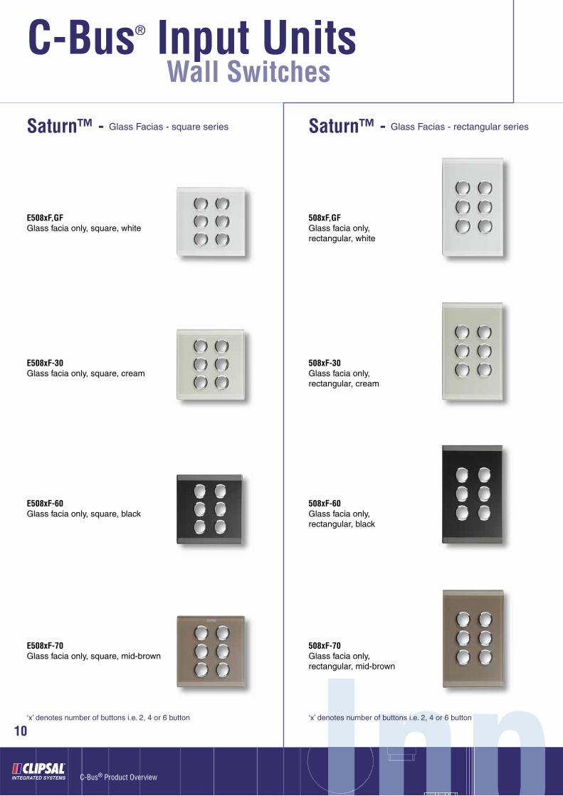
E508xF,GFGlass facia only, square, white
Saturn™ - Glass Facias - square series
E508xF-30Glass facia only, square, cream
E508xF-60Glass facia only, square, black
E508xF-70Glass facia only, square, mid-brown
Saturn™ - Glass Facias - rectangular series
508xF,GFGlass facia only, rectangular, white
508xF-30Glass facia only, rectangular, cream
508xF-60Glass facia only, rectangular, black
508xF-70Glass facia only, rectangular, mid-brown
‘x’ denotes number of buttons i.e. 2, 4 or 6 button‘x’ denotes number of buttons i.e. 2, 4 or 6 button
ut UnitsUnitsut Unitsnut Unnits11
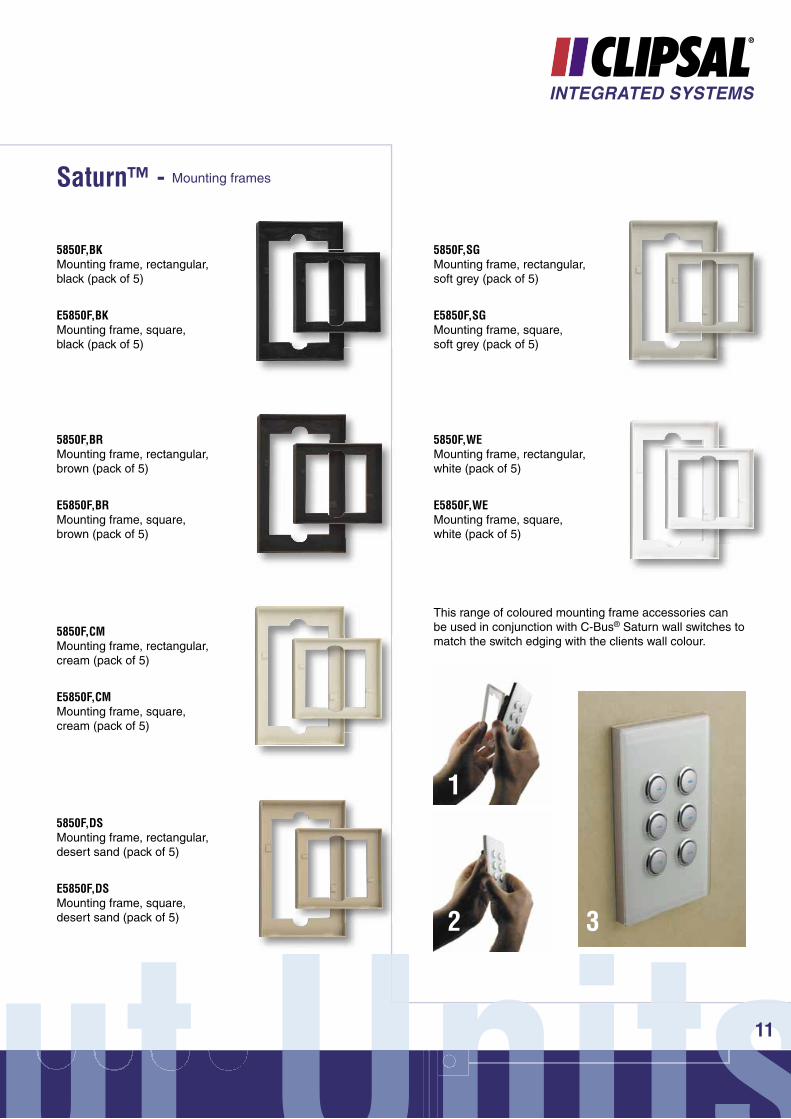
Saturn™ - Mounting frames
5850F,SGMounting frame, rectangular, soft grey (pack of 5)
5850F,WEMounting frame, rectangular, white (pack of 5)
5850F,BKMounting frame, rectangular, black (pack of 5)
E5850F,BKMounting frame, square, black (pack of 5)
5850F,BRMounting frame, rectangular, brown (pack of 5)
E5850F,BRMounting frame, square, brown (pack of 5)
5850F,CMMounting frame, rectangular, cream (pack of 5)
E5850F,CMMounting frame, square, cream (pack of 5)
5850F,DSMounting frame, rectangular, desert sand (pack of 5)
E5850F,DSMounting frame, square, desert sand (pack of 5)
1
2 3
This range of coloured mounting frame accessories can be used in conjunction with C-Bus® Saturn wall switches to match the switch edging with the clients wall colour.
E5850F,SGMounting frame, square, soft grey (pack of 5)
E5850F,WEMounting frame, square, white (pack of 5)
C-Bus® Input Units®
Wall Switches
C-Bus® Product Overview
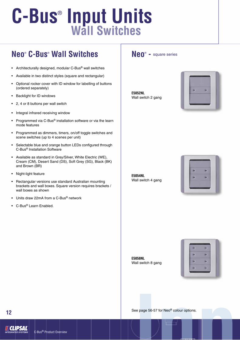
• Architecturally designed, modular C-Bus® wall switches
• Available in two distinct styles (square and rectangular)
• Optional rocker cover with ID window for labelling of buttons (ordered separately)
• Backlight for ID windows
• 2, 4 or 8 buttons per wall switch
• Integral infrared receiving window
• Programmed via C-Bus® installation software or via the learn mode features
• Programmed as dimmers, timers, on/off toggle switches and scene switches (up to 4 scenes per unit)
• Selectable blue and orange button LEDs confi gured through C-Bus® Installation Software
• Available as standard in Grey/Silver, White Electric (WE), Cream (CM), Desert Sand (DS), Soft Grey (SG), Black (BK) and Brown (BR)
• Night-light feature
• Rectangular versions use standard Australian mounting brackets and wall boxes. Square version requires brackets / wall boxes as shown
• Units draw 22mA from a C-Bus® network
• C-Bus® Learn Enabled.
E5052NLWall switch 2 gang
E5054NLWall switch 4 gang
E5058NLWall switch 8 gang
Neo® - square series
InpInpI pnnSee page 56-57 for Neo® colour options.12
Neo® C-Bus® Wall Switches
13
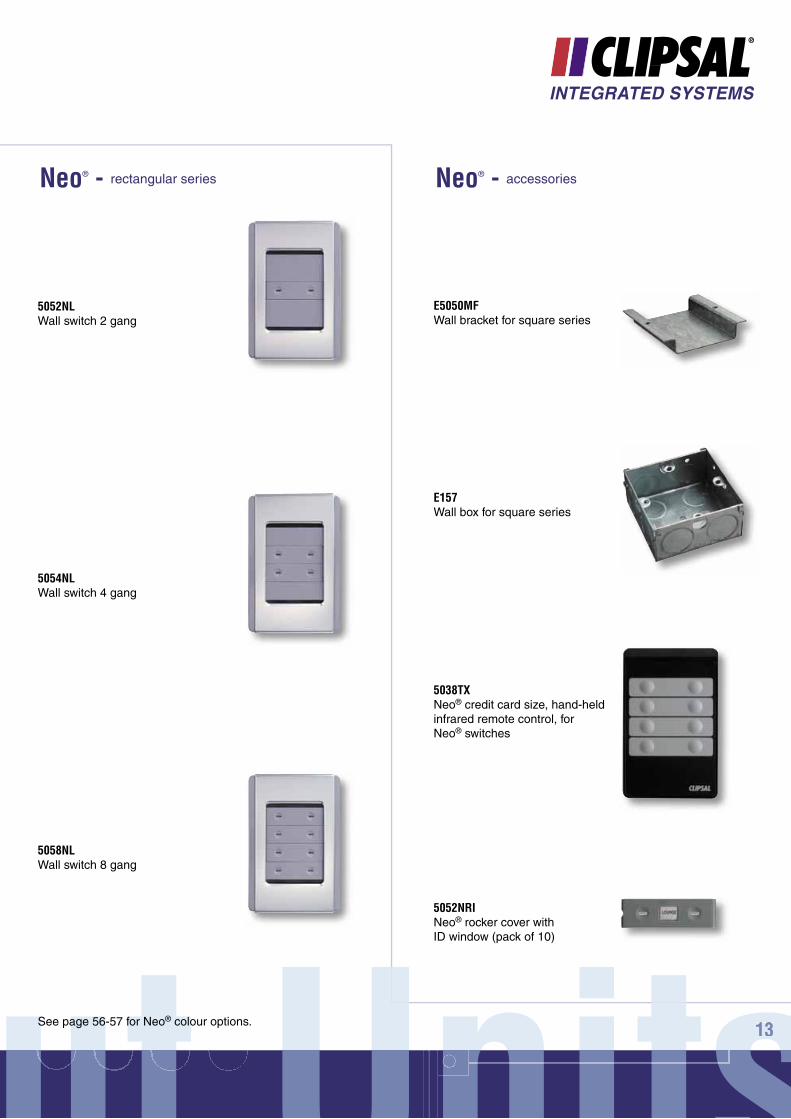
5052NLWall switch 2 gang
5054NLWall switch 4 gang
5058NLWall switch 8 gang
Neo® - rectangular series Neo® - accessories
E5050MFWall bracket for square series
E157Wall box for square series
5038TXNeo® credit card size, hand-held infrared remote control, for Neo® switches
5052NRINeo® rocker cover with ID window (pack of 10)
ut UnitsU itut Unitsnut Unnits1313See page 56-57 for Neo® colour options.
C-Bus® Input Units®
InpInpI pnn
Wall Switches
14
C-Bus® Product Overview
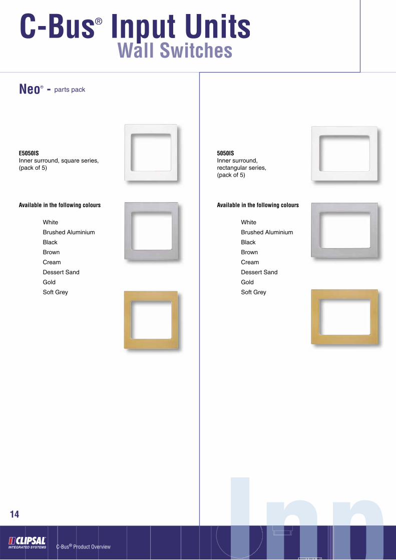
E5050ISInner surround, square series,(pack of 5)
5050ISInner surround, rectangular series, (pack of 5)
Neo® - parts pack
Available in the following colours
White
Brushed Aluminium
Black
Brown
Cream
Dessert Sand
Gold
Soft Grey
Available in the following colours
White
Brushed Aluminium
Black
Brown
Cream
Dessert Sand
Gold
Soft Grey
ut UnitsUnitsut Unitsnut Unnits15
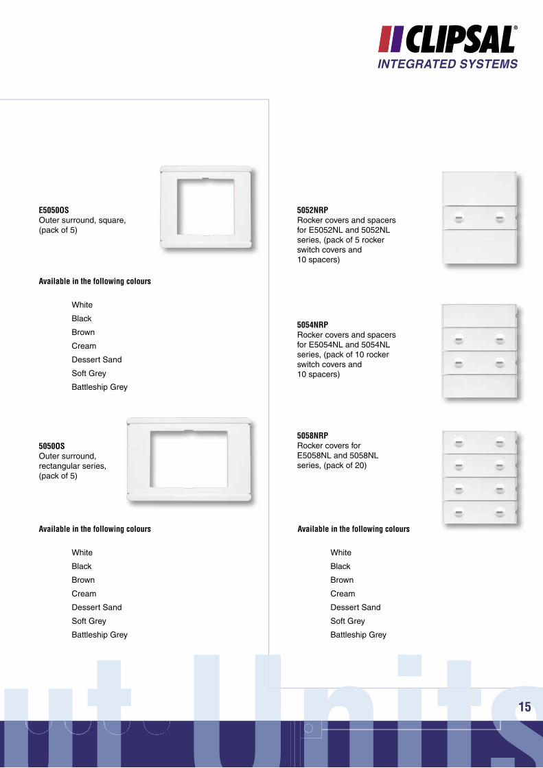
E5050OSOuter surround, square, (pack of 5)
5050OSOuter surround, rectangular series, (pack of 5)
5052NRPRocker covers and spacers for E5052NL and 5052NL series, (pack of 5 rocker switch covers and 10 spacers)
Available in the following colours
White
Black
Brown
Cream
Dessert Sand
Soft Grey
Battleship Grey
Available in the following colours
White
Black
Brown
Cream
Dessert Sand
Soft Grey
Battleship Grey
Available in the following colours
White
Black
Brown
Cream
Dessert Sand
Soft Grey
Battleship Grey
5054NRPRocker covers and spacers for E5054NL and 5054NL series, (pack of 10 rocker switch covers and 10 spacers)
5058NRPRocker covers for E5058NL and 5058NL series, (pack of 20)
C-Bus® Input Units®
InpInpI pnn
Wall Switches
16
C-Bus® Product Overview
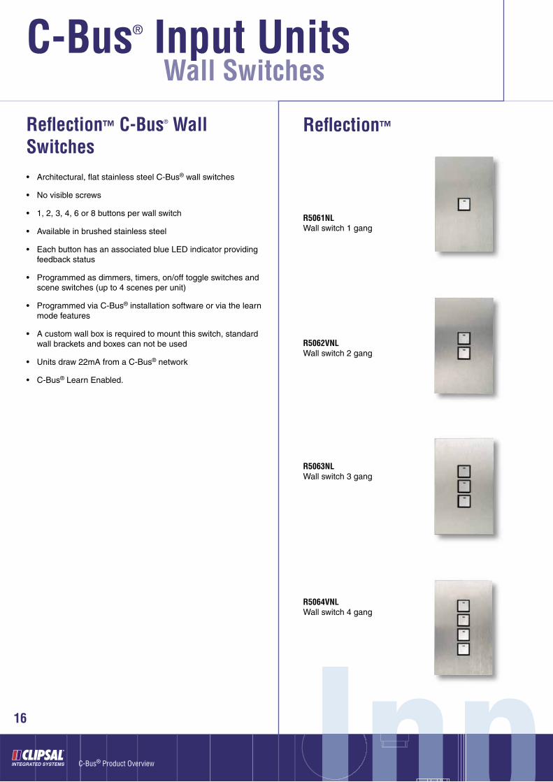
Refl ection™
• Architectural, fl at stainless steel C-Bus® wall switches
• No visible screws
• 1, 2, 3, 4, 6 or 8 buttons per wall switch
• Available in brushed stainless steel
• Each button has an associated blue LED indicator providing feedback status
• Programmed as dimmers, timers, on/off toggle switches and scene switches (up to 4 scenes per unit)
• Programmed via C-Bus® installation software or via the learn mode features
• A custom wall box is required to mount this switch, standard wall brackets and boxes can not be used
• Units draw 22mA from a C-Bus® network
• C-Bus® Learn Enabled.
Refl ection™ C-Bus® Wall Switches
R5061NLWall switch 1 gang
R5062VNLWall switch 2 gang
R5063NLWall switch 3 gang
R5064VNLWall switch 4 gang

ut Unitsut Unitsnut Unnits17
R5066NLWall switch, 6 gang
R5068NLWall switch, 8 gang
R5060WBWallbox to suit Refl ection™ range of wall switches
Important note: This wall box must be used to install Refl ection™ Wall switches
2000 Series C-Bus® Wall Switches
• May be programmed as dimmers, timers and on/off toggle switches
• 1, 2 or 4 buttons per wall switch
• Each unit features a programmable status indicator
• Available in a wide range of colours (See page 57 for colour options)
• Units draw 18mA from a C-Bus® network
• C-Bus® Learn Enabled
5031NLWall switch, 1 gang, rectangular
5032NLWall switch, 2 gang, rectangular
5034NLWall switch, 4 gang, rectangular
E5031NLWall switch, 1 gang, square
E5032NLWall switch, 2 gang, square
E5034NLWall switch, 4 gang, square
5031NL
Classic C2000 Series C-Bus® Wall Switches
• May be programmed as dimmers, timers and on/off toggle switches
• 1, 2 or 4 buttons per wall switch
• Each unit features a programmable status indicator
• Available in a wide range of colours (See page 57 for colour options)
• Units draw 18mA from a C-Bus® network
• C-Bus® Learn Enabled
C5031NLWall switch, 1 gang
C5032NLWall switch, 2 gang
C5034NLWall switch, 4 gang
C5031NL
Refl ection™ - accessories
E5031NL
C-Bus® Input Units®
InpInpI pnn
Wall Switches
18
C-Bus® Product Overview
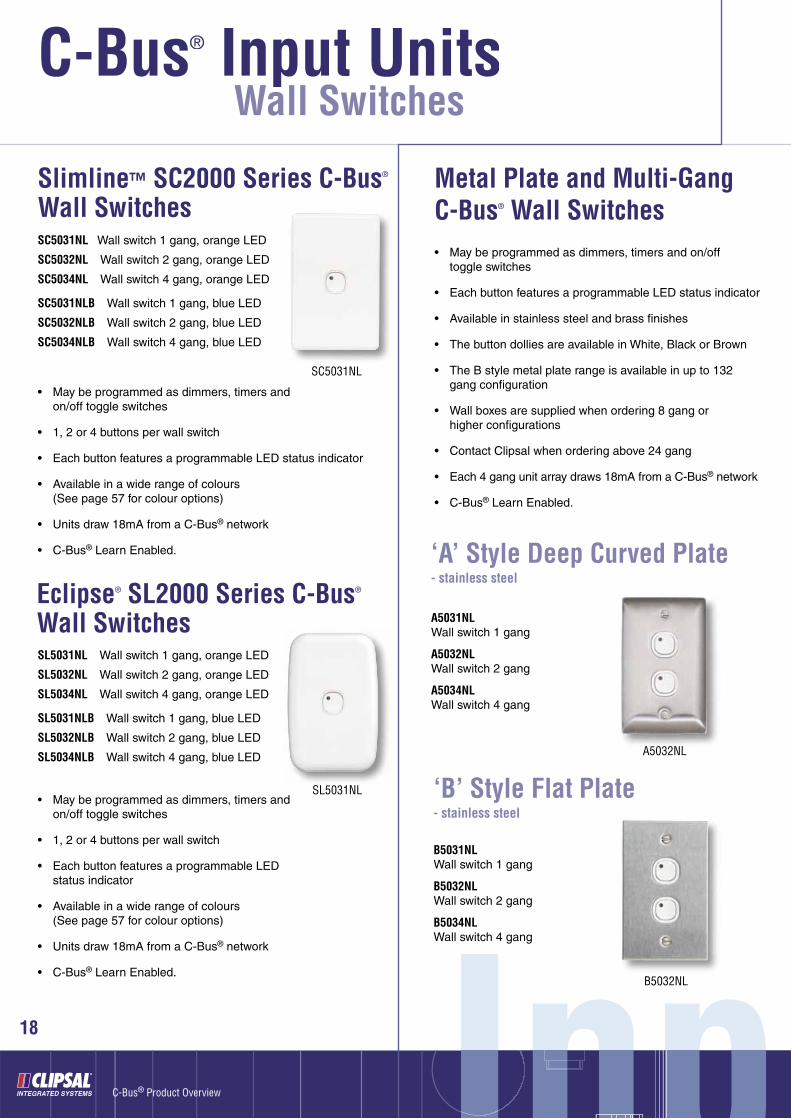
Slimline™ SC2000 Series C-Bus® Wall Switches
• May be programmed as dimmers, timers and on/off toggle switches
• 1, 2 or 4 buttons per wall switch
• Each button features a programmable LED status indicator
• Available in a wide range of colours(See page 57 for colour options)
• Units draw 18mA from a C-Bus® network
• C-Bus® Learn Enabled.
SC5031NL Wall switch 1 gang, orange LED
SC5032NL Wall switch 2 gang, orange LED
SC5034NL Wall switch 4 gang, orange LED
SC5031NLB Wall switch 1 gang, blue LED
SC5032NLB Wall switch 2 gang, blue LED
SC5034NLB Wall switch 4 gang, blue LED
SC5031NL
Eclipse® SL2000 Series C-Bus® Wall Switches
• May be programmed as dimmers, timers and on/off toggle switches
• 1, 2 or 4 buttons per wall switch
• Each button features a programmable LED status indicator
• Available in a wide range of colours(See page 57 for colour options)
• Units draw 18mA from a C-Bus® network
• C-Bus® Learn Enabled.
SL5031NL Wall switch 1 gang, orange LED
SL5032NL Wall switch 2 gang, orange LED
SL5034NL Wall switch 4 gang, orange LED
SL5031NLB Wall switch 1 gang, blue LED
SL5032NLB Wall switch 2 gang, blue LED
SL5034NLB Wall switch 4 gang, blue LED
SL5031NL
Metal Plate and Multi-Gang C-Bus® Wall Switches • May be programmed as dimmers, timers and on/off
toggle switches
• Each button features a programmable LED status indicator
• Available in stainless steel and brass fi nishes
• The button dollies are available in White, Black or Brown
• The B style metal plate range is available in up to 132 gang confi guration
• Wall boxes are supplied when ordering 8 gang or higher confi gurations
• Contact Clipsal when ordering above 24 gang
• Each 4 gang unit array draws 18mA from a C-Bus® network
• C-Bus® Learn Enabled.
‘A’ Style Deep Curved Plate- stainless steel
A5031NLWall switch 1 gang
A5032NLWall switch 2 gang
A5034NLWall switch 4 gang
A5032NL
‘B’ Style Flat Plate- stainless steel
B5031NLWall switch 1 gang
B5032NLWall switch 2 gang
B5034NLWall switch 4 gang
B5032NL
ut UnitsUnitsut Unitsnut Unnits19
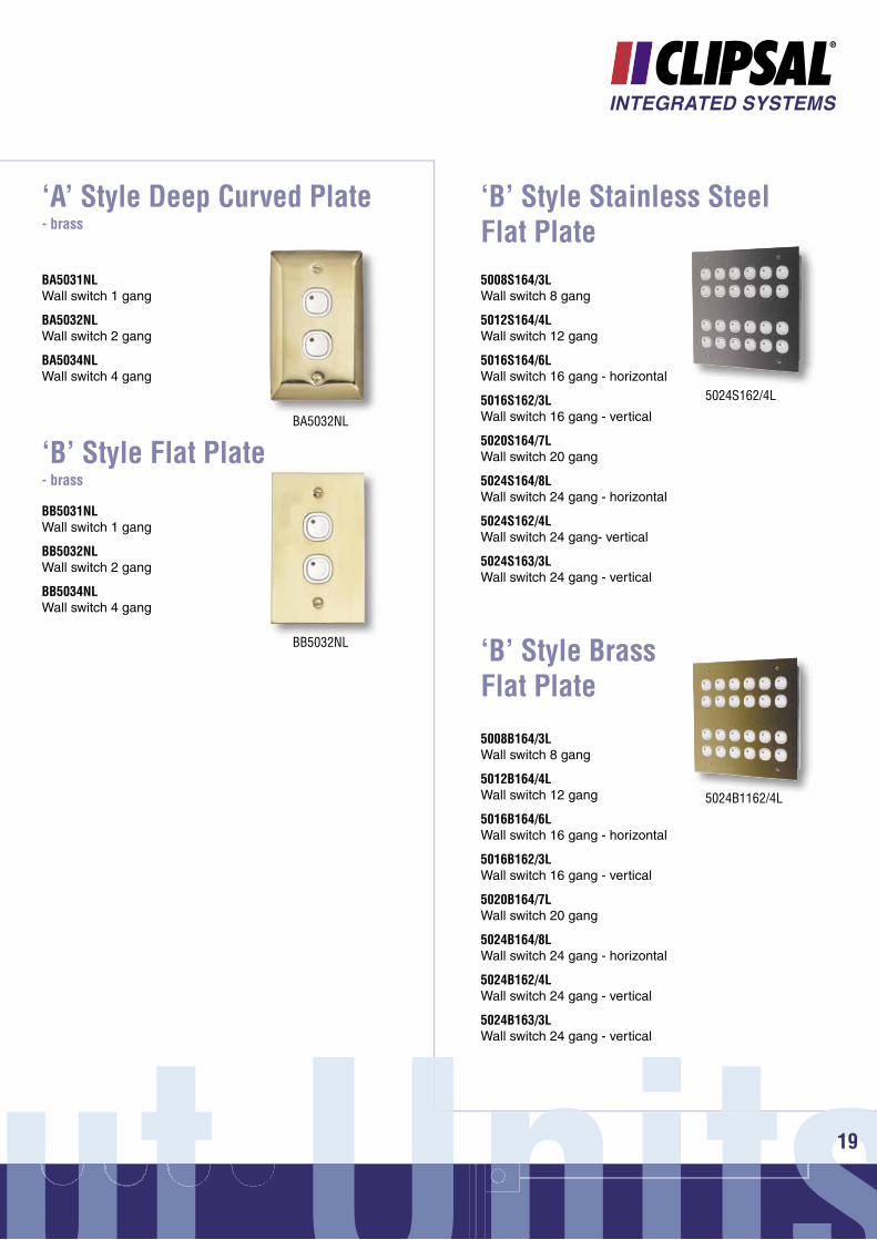
‘A’ Style Deep Curved Plate- brass
BA5031NLWall switch 1 gang
BA5032NLWall switch 2 gang
BA5034NLWall switch 4 gang
BA5032NL
‘B’ Style Flat Plate- brass
BB5031NLWall switch 1 gang
BB5032NLWall switch 2 gang
BB5034NLWall switch 4 gang
BB5032NL
‘B’ Style Stainless Steel Flat Plate5008S164/3LWall switch 8 gang
5012S164/4LWall switch 12 gang
5016S164/6LWall switch 16 gang - horizontal
5016S162/3LWall switch 16 gang - vertical
5020S164/7LWall switch 20 gang
5024S164/8LWall switch 24 gang - horizontal
5024S162/4LWall switch 24 gang- vertical
5024S163/3LWall switch 24 gang - vertical
5024S162/4L
‘B’ Style Brass Flat Plate
5008B164/3LWall switch 8 gang
5012B164/4LWall switch 12 gang
5016B164/6LWall switch 16 gang - horizontal
5016B162/3LWall switch 16 gang - vertical
5020B164/7LWall switch 20 gang
5024B164/8LWall switch 24 gang - horizontal
5024B162/4LWall switch 24 gang - vertical
5024B163/3LWall switch 24 gang - vertical
5024B1162/4L

C-Bus® Input Units®
InpInpI pnn20
C-Bus® Product Overview
5504GIGeneral input unit, 4 channel
General Analogue/Digital Input Unit
• Four channel general input unit, DIN rail mounted
• 8M DIN Modules Wide
• Dimensions 144mm x 85mm x 65mm
• Used to interface a C-Bus® system to third party products such as light level sensors, current sensors, temperature sensors, CO2 detectors, differential sensors, pressure sensors, fl ow rate sensors, moisture probes etc
• Designed to either trigger the state of a C-Bus® group address as a function of input level or broadcast a message on the C-Bus® network, representing the input level
• Maximum of 10 units on a single C-Bus® network
• Can be used to measure analogue values (0-1V, 0-5V, 0-10V, 0-20V, 0-20mA, 4-20mA, 500 Ohm, 1k Ohm, 3k Ohm and 10k Ohm thermistor inputs)
• Requires a 24V dc connection (power pack included)
• Units draw 18mA from a C-Bus® network.
General Input Units
5104BCLBus coupler input unit, 4 channel
Bus Coupler Input Units
• 5104BCL used to interface up to 4 standard voltage free mechanical switches, including latching and toggle switches to C-Bus®
• 5102BCLEDL used to interface up to 2 standard voltage free mechanical switches, including latching and toggle switches to C-Bus®, incorporates remote LED facility
• Dimensions 55mm x 49mm x 18mm
• The unit is designed to fi t into a standard wall box
• Each unit features a programmable status indicator
• The maximum distance between the unit and an external voltage free switch is limited to 1 metre (use L5504AUX if longer distance required)
• Units draw 18mA from a C-Bus® network
• C-Bus® Learn Enabled.
5102BCLEDLBus coupler input unit, 2 channel, with remote LED facility
ut UnitsUnitsut Unitsnut Unnits21
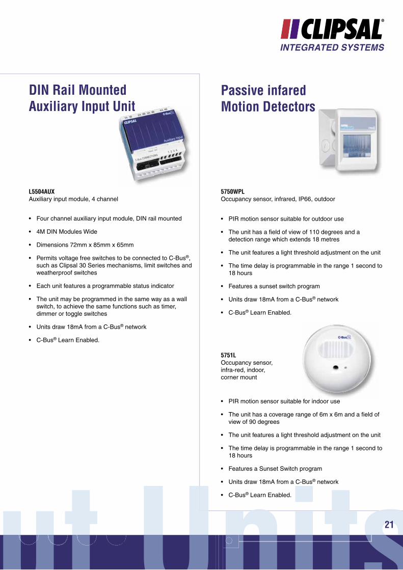
DIN Rail Mounted Auxiliary Input Unit
L5504AUXAuxiliary input module, 4 channel
• Four channel auxiliary input module, DIN rail mounted
• 4M DIN Modules Wide
• Dimensions 72mm x 85mm x 65mm
• Permits voltage free switches to be connected to C-Bus®, such as Clipsal 30 Series mechanisms, limit switches and weatherproof switches
• Each unit features a programmable status indicator
• The unit may be programmed in the same way as a wall switch, to achieve the same functions such as timer, dimmer or toggle switches
• Units draw 18mA from a C-Bus® network
• C-Bus® Learn Enabled.
Passive infared Motion Detectors
5750WPLOccupancy sensor, infrared, IP66, outdoor
• PIR motion sensor suitable for outdoor use
• The unit has a fi eld of view of 110 degrees and a detection range which extends 18 metres
• The unit features a light threshold adjustment on the unit
• The time delay is programmable in the range 1 second to 18 hours
• Features a sunset switch program
• Units draw 18mA from a C-Bus® network
• C-Bus® Learn Enabled.
5751LOccupancy sensor, infra-red, indoor, corner mount
• PIR motion sensor suitable for indoor use
• The unit has a coverage range of 6m x 6m and a fi eld of view of 90 degrees
• The unit features a light threshold adjustment on the unit
• The time delay is programmable in the range 1 second to 18 hours
• Features a Sunset Switch program
• Units draw 18mA from a C-Bus® network
• C-Bus® Learn Enabled.
C-Bus® Input Units®
InpInpI pnn22
C-Bus® Product Overview
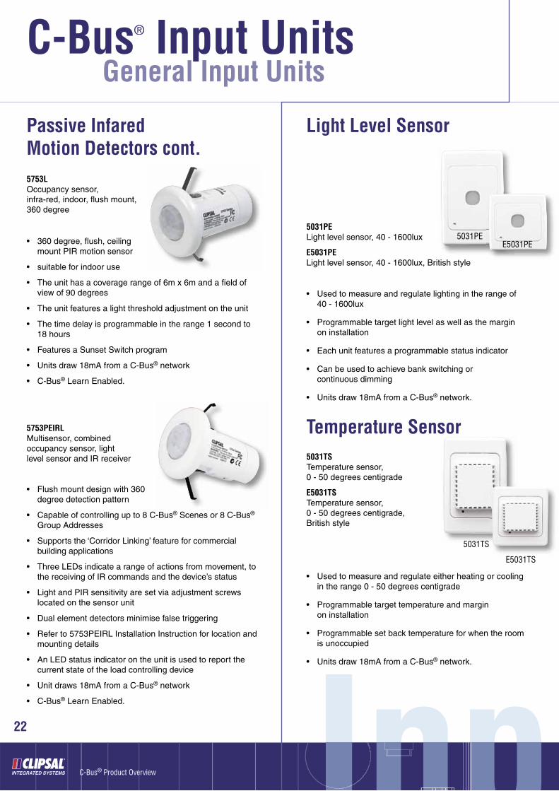
5031TSTemperature sensor, 0 - 50 degrees centigrade
E5031TSTemperature sensor, 0 - 50 degrees centigrade, British style
Temperature Sensor
• Used to measure and regulate either heating or cooling in the range 0 - 50 degrees centigrade
• Programmable target temperature and margin on installation
• Programmable set back temperature for when the room is unoccupied
• Units draw 18mA from a C-Bus® network.
Passive Infared Motion Detectors cont.
5031PELight level sensor, 40 - 1600lux
E5031PELight level sensor, 40 - 1600lux, British style
Light Level Sensor
• Used to measure and regulate lighting in the range of 40 - 1600lux
• Programmable target light level as well as the margin on installation
• Each unit features a programmable status indicator
• Can be used to achieve bank switching or continuous dimming
• Units draw 18mA from a C-Bus® network.
5753LOccupancy sensor, infra-red, indoor, fl ush mount, 360 degree
• 360 degree, fl ush, ceiling mount PIR motion sensor
• suitable for indoor use
• The unit has a coverage range of 6m x 6m and a fi eld of view of 90 degrees
• The unit features a light threshold adjustment on the unit
• The time delay is programmable in the range 1 second to 18 hours
• Features a Sunset Switch program
• Units draw 18mA from a C-Bus® network
• C-Bus® Learn Enabled.
5753PEIRLMultisensor, combined occupancy sensor, light level sensor and IR receiver
• Flush mount design with 360 degree detection pattern
• Capable of controlling up to 8 C-Bus® Scenes or 8 C-Bus® Group Addresses
• Supports the ‘Corridor Linking’ feature for commercial building applications
• Three LEDs indicate a range of actions from movement, to the receiving of IR commands and the device’s status
• Light and PIR sensitivity are set via adjustment screws located on the sensor unit
• Dual element detectors minimise false triggering
• Refer to 5753PEIRL Installation Instruction for location and mounting details
• An LED status indicator on the unit is used to report the current state of the load controlling device
• Unit draws 18mA from a C-Bus® network
• C-Bus® Learn Enabled.
5031PEE5031PE
5031TS
E5031TS
General Input Units

ut UnitsUnitsut Unitsnut Unnits23
5070THPRC-Bus® thermostat, programmable, 4 zone, with 5 Relays (relays for HVAC plant control only, not accessible via C-Bus®)
5070THPC-Bus® thermostat, programmable, 4 zone, no on board HVAC plant control relays
4 Zone Thermostat with programmable time scheduling
• Four zone (plus the common zone) programmable C-Bus® thermostat
• Wall mounted
• Dimensions 105mm x 149mm x 24mm
• Support for control of HVAC units via C-Bus® or directly using on board HVAC relays (RWG control)
• Manually adjustable temperature set point, mode of operation (heating, cooling or ventilation) and time schedules
• On board 7 day HVAC time scheduling (user programmable), manual fan speed control, and setback mode
• Easy to use interface, comprising of an LCD, manual control buttons and a rotating dial with an integral press switch
• Draws 40mA from a C-Bus® network.
5070THBRC-Bus® thermostat, programmable, single zone with 5 relays (relays for HVAC plant control only, not accessibile via C-Bus®)
• Single zone C-Bus® thermostat
• Wall Mounted
• Dimensions 92mm x 127mm x 24mm
• Support for control of HVAC units via C-Bus® or the internal HVAC relays (‘RWG’ control)
• Manually adjustable temperature set point and mode of operation (heating, cooling or ventilation)
• The unit includes fan speed control and a ‘Setback’ or ‘Economy’ Mode
• Easy to use operator interface includes an integral LCD to display the current temperature and mode of operation
• Draws 40mA from a C-Bus® network.
5070THBC-Bus® thermostat, programmable, single zone, no on board HVAC plant control relays
Single Zone Thermostat
C-Bus® Input Units®
InpInpI pnn
Wall Switches
24
C-Bus® Product Overview
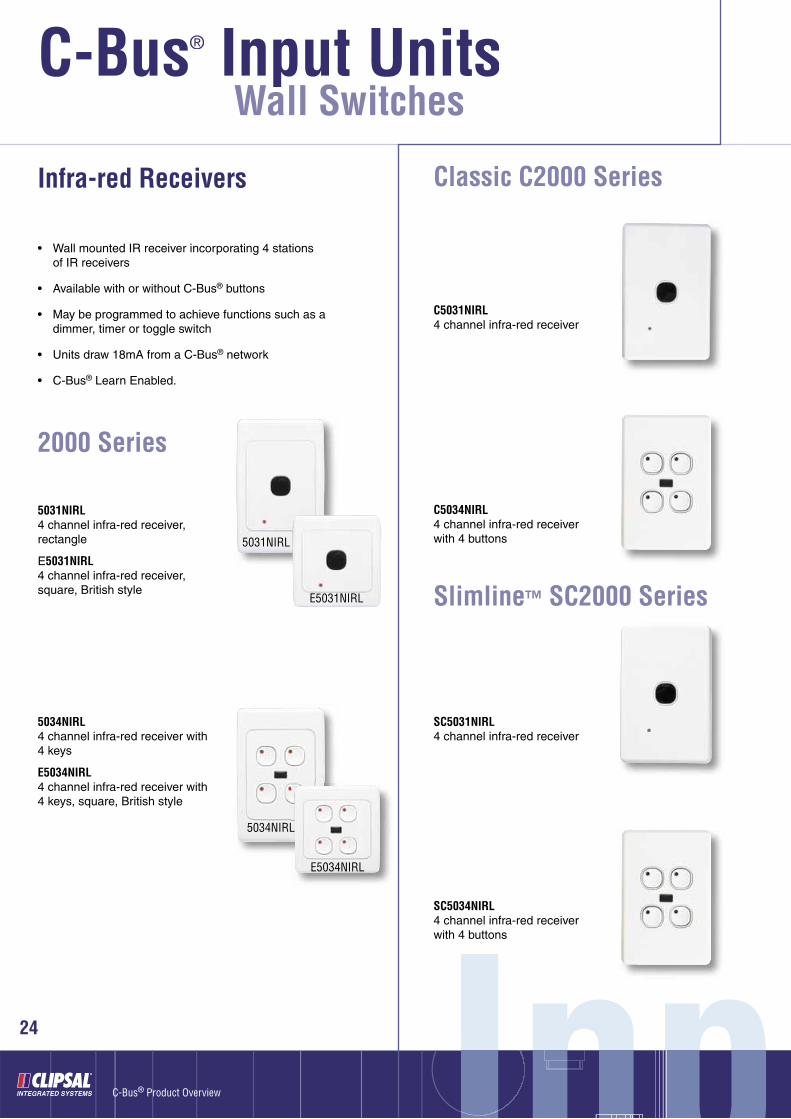
5031NIRL4 channel infra-red receiver,rectangle
E5031NIRL4 channel infra-red receiver, square, British style
Infra-red Receivers
• Wall mounted IR receiver incorporating 4 stations of IR receivers
• Available with or without C-Bus® buttons
• May be programmed to achieve functions such as a dimmer, timer or toggle switch
• Units draw 18mA from a C-Bus® network
• C-Bus® Learn Enabled.
5034NIRL4 channel infra-red receiver with 4 keys
E5034NIRL4 channel infra-red receiver with 4 keys, square, British style
2000 Series
C5031NIRL4 channel infra-red receiver
C5034NIRL4 channel infra-red receiver with 4 buttons
Classic C2000 Series
SC5031NIRL4 channel infra-red receiver
SC5034NIRL4 channel infra-red receiver with 4 buttons
Slimline™ SC2000 Series
5031NIRL
E5031NIRL
5034NIRL
E5034NIRL
ut UnitsUnitsut Unitsnut Unnits25
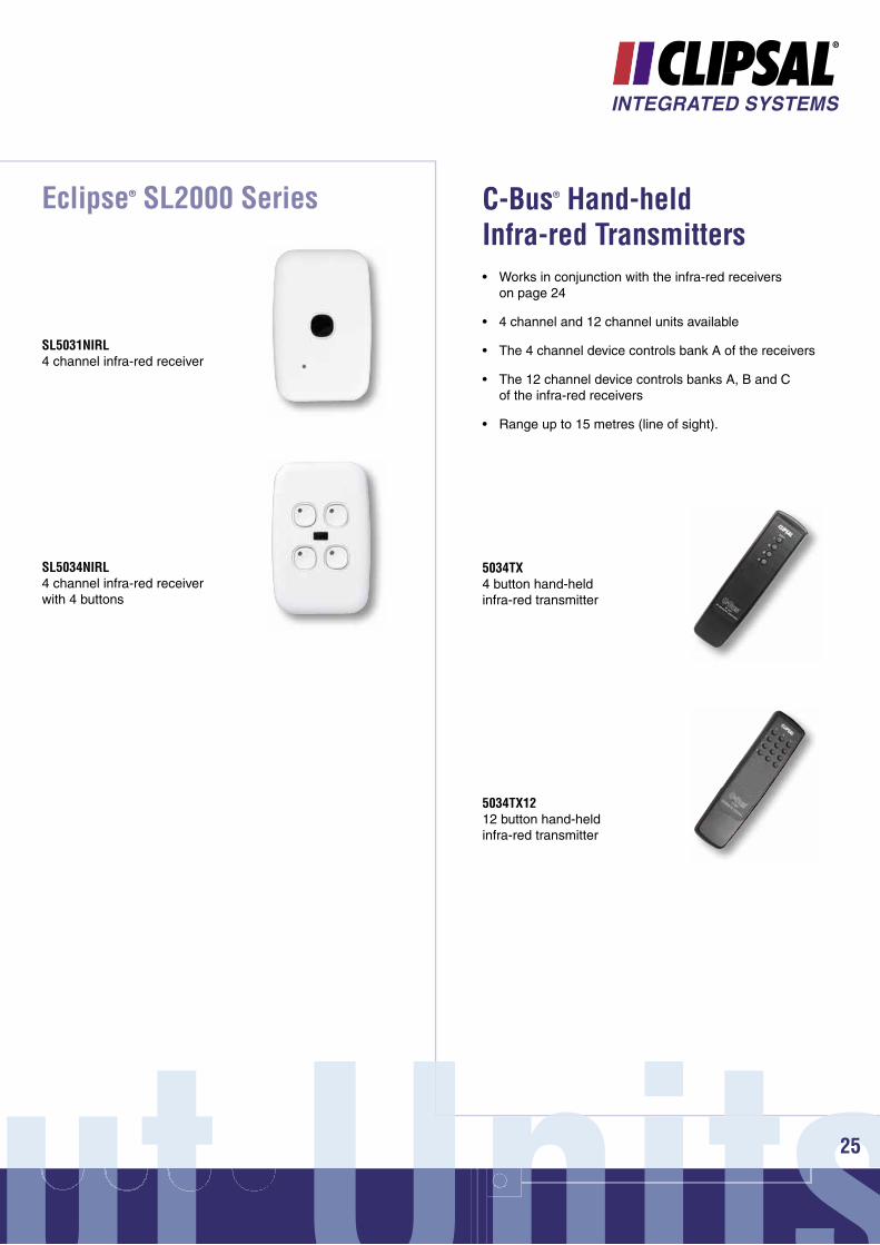
• Works in conjunction with the infra-red receivers on page 24
• 4 channel and 12 channel units available
• The 4 channel device controls bank A of the receivers
• The 12 channel device controls banks A, B and C of the infra-red receivers
• Range up to 15 metres (line of sight).
SL5031NIRL4 channel infra-red receiver
SL5034NIRL4 channel infra-red receiver with 4 buttons
Eclipse® SL2000 Series
5034TX4 button hand-held infra-red transmitter
C-Bus® Hand-held Infra-red Transmitters
5034TX1212 button hand-held infra-red transmitter

C-Bus® Input Units®
InpInpI pnn26
C-Bus® Product Overview
• Universal, hand held, infrared remote control unit for control of electronic devices equipped with an infrared (IR) remote
• Control of up to 16 devices including C-Bus®, DVDs, TVs, satellite receivers, VCRs and CDs
• Large touch screen display
• Blue LED backlighting
• LED indicators provide information and feedback on:
o Status of the beep feature (audible button press confi rmation)
o ‘Battery low’ warning
o Confi rmation of a successfully transmitted infrared code
o Error warning
o Touch screen page number.
• User programmable buttons for each device include 7 rubber buttons and 48 touch screen buttons
• Quick Control buttons
• Sleep button
• Page / date button
• Pre-programmed manufacturer codes for many models
• Incorporates imbedded C-Bus® IR codes for the C-Bus® 5038TX and 5035TX IR remote controls
• Easy to confi gure with new IR codes using the “learning eye”
• Macro function (up to 60 commands per macro)
• Learning IR codes from existing remote controls.
5030URCUniversal Infra-red Remote Control Unit, with LCD touch screen
Universal Infra-red Remote Control Unit
Remote Control Units
ut UnitsUnitsut Unitsnut Unnits27
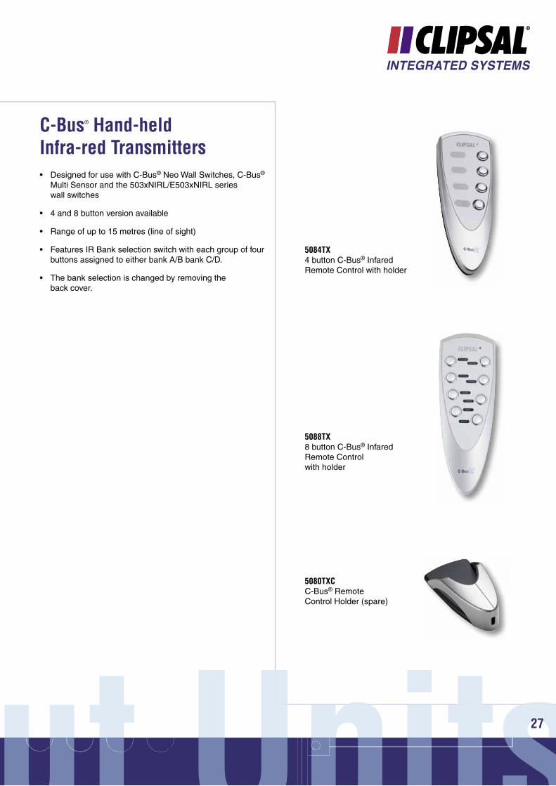
5084TX4 button C-Bus® Infared Remote Control with holder
5088TX8 button C-Bus® Infared Remote Control with holder
5080TXCC-Bus® Remote Control Holder (spare)
• Designed for use with C-Bus® Neo Wall Switches, C-Bus® Multi Sensor and the 503xNIRL/E503xNIRL series wall switches
• 4 and 8 button version available
• Range of up to 15 metres (line of sight)
• Features IR Bank selection switch with each group of four buttons assigned to either bank A/B bank C/D.
• The bank selection is changed by removing the back cover.
C-Bus® Hand-held Infra-red Transmitters

C-Bus® Input Units®
InpInpI pnn28
C-Bus® Product Overview
5034NS4 channel scene controller, rectangle
E5034NS4 channel scene controller, square
• Allow up to 4 scenes or moods to be set fromone switch
• Each time a button is pressed the scene is issued
• Up to 9 turn on/off or 6 ramp commands may be programmed on each button
• Units draw 18mA from a C-Bus® network.
Scene Controllers
C5034NS4 channel scene controller
2000 Series
Classic C2000 Series
SC5034NS4 channel scene controller
SL5034NS4 channel scene controller
Slimline™ SC2000 Series
Eclipse® SL2000 Series
Scene Controllers, Standard Range

ut UnitsUnitsut Unitsnut Unnits29
5035NIRSL,WE5 key scene controller with IR, white
• Scene Controller with IR capability features 5 preset buttons
• Dimensions 175mm x 88mm x 23.3mm
• Additional master off button
• Scenes and Master OFF functions accessible from the unit or IR remote control (supplied)
• Facility to set up to 5 scenes on each unit and up to 9 Group Addresses may be associated with each scene
• The unit may be programmed with the C-Bus® application software
• Scene may be set from the unit itself via learn enabled features
• Units draw 32mA from a C-Bus® network
• C-Bus® Learn Enabled.
Scene Master® Scene Controllers
5035NIRSLTR,WE5 key scene controller with IR, white with smoked transparent cover
5035NIRSLTR,GB5 key scene controller with IR, grey and silver with smoked transparent cover
5035TXRemote control to suit Scene Master (spare)
C-Bus® Input Units®
InpInpI pnn30
C-Bus® Product Overview
Touch Screens
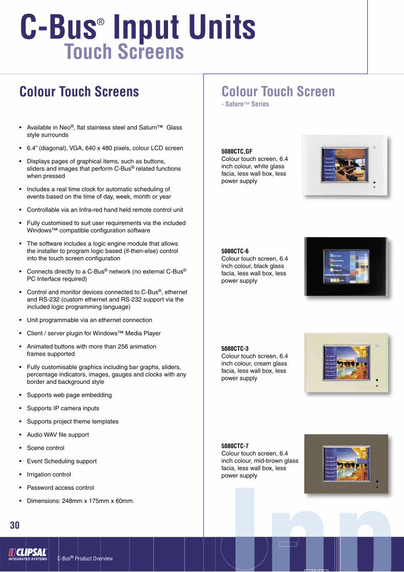
Colour Touch Screens
• Available in Neo®, fl at stainless steel and Saturn™ Glass style surrounds
• 6.4” (diagonal), VGA, 640 x 480 pixels, colour LCD screen
• Displays pages of graphical items, such as buttons, sliders and images that perform C-Bus® related functions when pressed
• Includes a real time clock for automatic scheduling of events based on the time of day, week, month or year
• Controllable via an Infra-red hand held remote control unit
• Fully customised to suit user requirements via the included Windows™ compatible confi guration software
• The software includes a logic engine module that allows the installer to program logic based (if-then-else) control into the touch screen confi guration
• Connects directly to a C-Bus® network (no external C-Bus® PC Interface required)
• Control and monitor devices connected to C-Bus®, ethernet and RS-232 (custom ethernet and RS-232 support via the included logic programming language)
• Unit programmable via an ethernet connection
• Client / server plugin for Windows™ Media Player
• Animated buttons with more than 256 animation frames supported
• Fully customisable graphics including bar graphs, sliders, percentage indicators, images, gauges and clocks with any border and background style
• Supports web page embedding
• Supports IP camera inputs
• Supports project theme templates
• Audio WAV fi le support
• Scene control
• Event Scheduling support
• Irrigation control
• Password access control
• Dimensions: 248mm x 175mm x 60mm.
Colour Touch Screen- Saturn™ Series
5080CTC-6Colour touch screen, 6.4 inch colour, black glass facia, less wall box, less power supply
5080CTC-3Colour touch screen, 6.4 inch colour, cream glass facia, less wall box, less power supply
5080CTC,GFColour touch screen, 6.4 inch colour, white glass facia, less wall box, less power supply
5080CTC-7Colour touch screen, 6.4 inch colour, mid-brown glass facia, less wall box, less power supply
ut UnitsUnitsut Unitsnut Unnits31
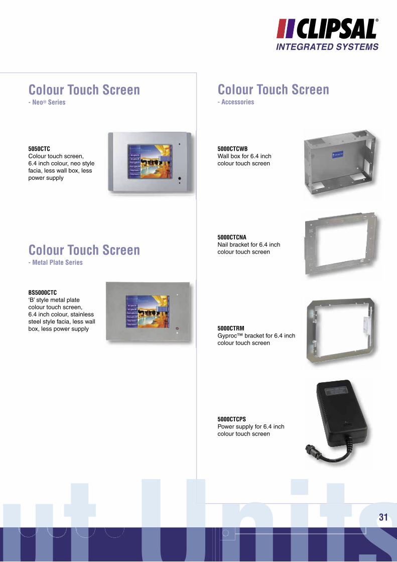
Colour Touch Screen- Neo® Series
5050CTCColour touch screen, 6.4 inch colour, neo style facia, less wall box, less power supply
Colour Touch Screen- Metal Plate Series
Colour Touch Screen- Accessories
5000CTCWBWall box for 6.4 inch colour touch screen
5000CTCNANail bracket for 6.4 inch colour touch screen
5000CTRMGyproc™ bracket for 6.4 inch colour touch screen
5000CTCPSPower supply for 6.4 inch colour touch screen
BS5000CTC‘B’ style metal plate colour touch screen, 6.4 inch colour, stainless steel style facia, less wall box, less power supply
C-Bus® Input Units®
InpInpI pnn32
C-Bus® Product Overview
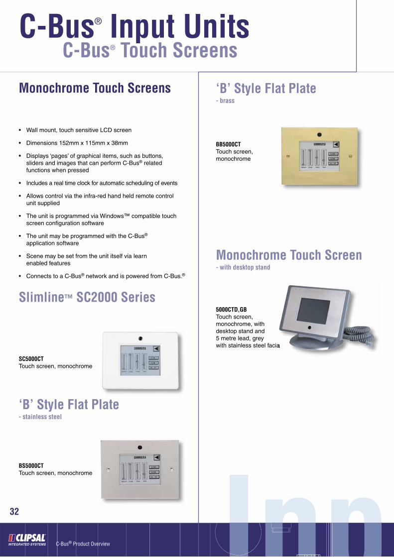
SC5000CTTouch screen, monochrome
• Wall mount, touch sensitive LCD screen
• Dimensions 152mm x 115mm x 38mm
• Displays ‘pages’ of graphical items, such as buttons, sliders and images that can perform C-Bus® related functions when pressed
• Includes a real time clock for automatic scheduling of events
• Allows control via the infra-red hand held remote control unit supplied
• The unit is programmed via Windows™ compatible touch screen confi guration software
• The unit may be programmed with the C-Bus® application software
• Scene may be set from the unit itself via learn enabled features
• Connects to a C-Bus® network and is powered from C-Bus.®
BS5000CTTouch screen, monochrome
Slimline™ SC2000 Series
‘B’ Style Flat Plate- stainless steel
BB5000CTTouch screen, monochrome
‘B’ Style Flat Plate- brass
C-Bus® Touch Screens
Monochrome Touch Screens
Monochrome Touch Screen - with desktop stand
5000CTD,GBTouch screen, monochrome, with desktop stand and 5 metre lead, grey with stainless steel facia

ut UnitsUnitsut Unitsnut Unnits33
Neo® Series - accessories
5050CTSSurround only, Neo® style, for use with monochrome touch screen
Monochrome Touch Screen - wall box
5000CTWBWall box for C-Bus® monochrome touch screen
Dimmer Units
OutpOutpu ptOutO34
C-Bus® Product Overview
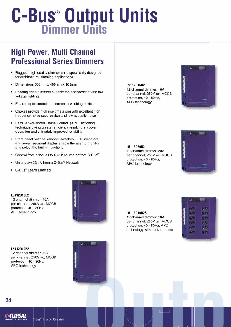
• Rugged, high quality dimmer units specifi cally designed for architectural dimming applications
• Dimensions 533mm x 486mm x 163mm
• Leading edge dimmers suitable for incandescent and low voltage lighting
• Feature opto-controlled electronic switching devices
• Chokes provide high rise time along with excellent high frequency noise suppression and low acoustic noise
• Feature “Advanced Phase Control” (APC) switching technique giving greater effi ciency resulting in cooler operation and ultimately improved reliability
• Front panel buttons, channel switches, LED indicators and seven-segment display enable the user to monitor and select the built-in functions
• Control from either a DMX-512 source or from C-Bus®
• Units draw 22mA from a C-Bus® Network
• C-Bus® Learn Enabled.
High Power, Multi Channel Professional Series Dimmers
L5112D10B212 channel dimmer, 10A per channel, 250V ac, MCCB protection, 40 - 80Hz, APC technology
L5112D12B212 channel dimmer, 12A per channel, 250V ac, MCCB protection, 40 - 80Hz, APC technology
L5112D16B212 channel dimmer, 16A per channel, 250V ac, MCCB protection, 40 - 80Hz, APC technology
L5112D20B212 channel dimmer, 20A per channel, 250V ac, MCCB protection, 40 - 80Hz, APC technology
L5112D10B2S12 channel dimmer, 10A per channel, 250V ac, MCCB protection, 40 - 80Hz, APC technology with socket outlets
C-Bus® Output UnitsU it
®
ut Unitsut Unitsnut UnnitsUnits35
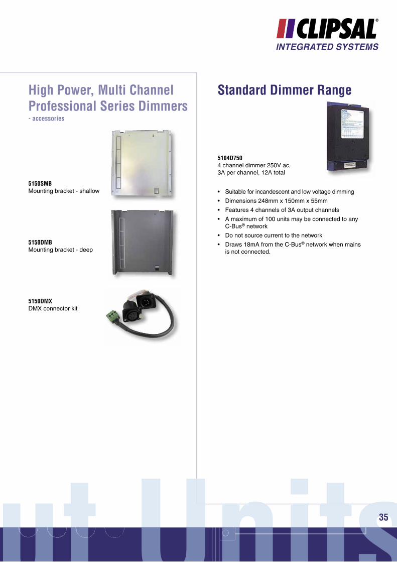
High Power, Multi Channel Professional Series Dimmers- accessories
5150SMBMounting bracket - shallow
5150DMBMounting bracket - deep
5150DMXDMX connector kit
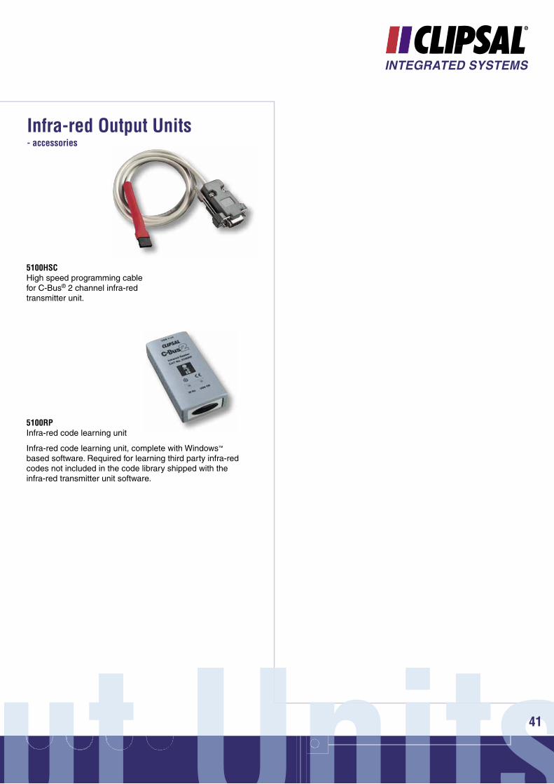
• Suitable for incandescent and low voltage dimming
• Dimensions 248mm x 150mm x 55mm
• Features 4 channels of 3A output channels
• A maximum of 100 units may be connected to any C-Bus® network
• Do not source current to the network
• Draws 18mA from the C-Bus® network when mainsis not connected.
Standard Dimmer Range
5104D7504 channel dimmer 250V ac, 3A per channel, 12A total

C-Bus® Output Units®
Dimmer Units
OutpOutpu ptOutO36
C-Bus® Product Overview
Professional Series Dimmers• Leading edge dimmers suitable for incandescent and low
voltage lighting
• Dimensions 240mm x 220mm x 75mm
• Feature an emergency lighting output in case of loss of mains power to the unit
• Incorporate a software selectable network burden and C-Bus® system clock
• Dimmers incorporate a 60mA power supply
• Up to 30 units may be connected to any C-Bus® network
• C-Bus® Learn Enabled.
L5104D54 channel dimmer 250V ac, 5A per channel, 20A total, 60mA inbuilt C-Bus® power supply
L5102D102 channel dimmer 250V ac, 10A per channel, 20A total, 60mA inbuilt C-Bus® power supply
L5101D201 channel dimmer 250V ac, 20A per channel, 20A total, 60mA inbuilt C-Bus® power supply

ut Unitsut Unitsnut UnnitsUnits37
DIN Rail Mounted Universal Dimmer Range
• 4 channel universal dimmer, DIN rail mounted
• 12M DIN modules wide
• Dimensions 215mm x 85mm x 65mm
• Features 4 channels of 2.5A rating
• Suitable for use with leading edge or trailing edge compatible low voltage transformers
• Suitable for low voltage electronic transformers, incandescent lamps and low voltage lamps with iron core transformers
• Features automatic load sensing
• Features a software selectable network burden and C-Bus® system clock
• A maximum of 10 units may be connected to a C-Bus® network
• Features an inbuilt 200mA C-Bus® power supply
• C-Bus® Learn Enabled.
L5504D2U4 channel C-Bus® universal dimmer 250V ac, 2.5A per channel, inbuilt 200mA C-Bus® power supply
• 4 channel universal dimmer, DIN rail mounted
• 12M DIN modules wide
• Dimensions 215mm x 85mm x 65mm
• Features 4 channels of 2.5A rating
• Suitable for use with leading edge or trailing edge compatible low voltage transformers
• Suitable for low voltage electronic transformers, incandescent lamps and low voltage lamps with iron core transformers
• Features automatic load sensing
• Features a software selectable network burden and C-Bus® system clock
• A maximum of 100 units may be connected to a C-Bus® network
• Does not source current to the network
• Draws 18mA from C-Bus® when mains is not connected
• C-Bus® Learn Enabled.
L5504D2UP4 Channel C-Bus® universal dimmer 250V ac, 2.5A per channel, no inbuilt C-Bus® power supply

C-Bus® Output Units®
Dimmer Units
OutpOutpu ptOutO38
C-Bus® Product Overview
• 8 channel dimmer, DIN rail mounted
• 12M DIN Modules Wide
• Dimensions 215mm x 85mm x 65mm
• Features 8 channels of 1A output, suitable for incandescent and low voltage lighting
• Features a software selectable network burden and C-Bus® system clock
• A maximum of 10 units may be connected to any C-Bus® network
• Features an inbuilt 200mA C-Bus® power supply
• C-Bus® Learn Enabled.
DIN Rail Mounted Dimmer Range
L5508D1A8 channel dimmer 250V ac, 1A per channel, inbuilt 200mA C-Bus® power supply
• 8 channel dimmer, DIN rail mounted
• 12M DIN modules wide
• Dimensions 215mm x 85mm x 65mm
• Features 8 channels of 1A output, suitable for incandescent and low voltage lighting
• Features a software selectable network burden and C-Bus® system clock
• A maximum of 100 units may be connected to any C-Bus® network
• Does not source current to the network
• Draws 18mA from the C-Bus® when mains is not connected
• C-Bus® Learn Enabled.
L5508D1AP8 channel dimmer 250V ac, 1A per channel, no inbuilt C-Bus® power supply
• 4 channel dimmer, DIN rail mounted
• 12M DIN modules wide
• Dimensions 215mm x 85mm x 65mm
• Features 4 channels of 2A output, suitable for incandescent and low voltage lighting
• Features a software selectable network burden and C-Bus® system clock
• A maximum of 10 units may be connected to any C-Bus® network
• Features a 200mA C-Bus® power supply
• C-Bus® Learn Enabled.
L5504D2A4 channel dimmer 250V ac, 2A per channel, inbuilt 200mA C-Bus® power supply
• 4 channel dimmer, DIN rail mounted
• 12M DIN modules wide
• Dimensions 215mm x 85mm x 65mm
• Features 4 channels of 2A output, suitable for incandes-cent and low voltage lighting
• Features a software selectable network burden and C-Bus® system clock
• A maximum of 100 units may be connected to any C-Bus® network
• Does not source current to the network
• Draws 18mA from the C-Bus® when mains is not connected
• C-Bus® Learn Enabled.
L5504D2AP4 channel dimmer 250V ac, 2A per channel, no inbuilt C-Bus® power supply

ut Unitsut Unitsnut UnnitsUnits39
L5508DSI8 channel dimmer for DSI electronic ballasts 250V ac, inbuilt 200mA C-Bus® power supply
• 8 channel dimmer for DSI ballasts, DIN rail mounted
• 12M DIN modules wide
• Dimensions 215mm x 85mm x 65mm
• Provides C-Bus® control of electronic DSI digital ballasts
• The module controls up to 100 DSI ballasts per channel
• Up to 10 units may be connected to any C-Bus® network
• Used in conjunction with electronic DSI ballasts
• The Dimmer features a 200mA C-Bus® power supply
• C-Bus® Learn Enabled.
C-Bus® DSI Gateway Range
• 8 channel dimmer for DSI ballasts, DIN rail mounted
• 12M DIN modules wide
• Dimensions 215mm x 85mm x 65mm
• Provides C-Bus® control of electronic DSI digital ballasts
• The module controls up to 100 DSI ballasts per channel
• Up to 100 units may be connected to any C-Bus® network
• Used in conjunction with electronic DSI ballasts
• Units draw 18mA from the C-Bus® network when mains is not connected
• C-Bus Learn Enabled.
L5508DSIP8 channel dimmer for DSI electronic ballasts 250V ac, no inbuilt C-Bus® power supply
• Analogue output module, DIN rail mounted
• 4M DIN modules wide
• Requires a 240V ac connection
• Dimensions 72mm x 85mm x 65mm
• Can either source or sink current and is used to drive most types of 0-10V electronic dimmable ballasts
• The unit provides 4 independent output channels
• Powered from C-Bus® and requires 18mA at 15 - 36Vdc for correct operation
• The polarity of the signal may be selected so that 0V corresponds to maximum or minimum brightness
• Units draw 18mA from the C-Bus® when mains is not connected
• C-Bus® Learn Enabled.
0-10V Analogue Output Unit
L5504AMP4 channel analogue output, 0-10V

C-Bus® Output Units®
OutpOutpu ptOutO40
C-Bus® Product Overview
Infra-red Output Units
• Transmits IR codes to third party devices
• Capable of broadcasting IR messages through two IR output channels (consist of 3.5mm mini audio mono sockets)
• Single or dual head emitter leads (ordered separately) should be connected to the output jacks
• Programmed via the High Speed Programing Cable (part number 5100HSC, ordered separately, see page 41)
• The installer has the facility to modify the stored codes using Windows™ based application software
• Stores a library of commonly used IR codes
• The Infrared Controller is based on the standard range of Clipsal 4-gang wall switches
• The standard colours are White Electric, Soft Grey, Desert Sand, Cream, Brown and Black
• Units draw 32mA from the C-Bus® network.
5034NIRT2 channel infra-red transmitter unit, 2000 Series wall plate
E5034NIRT2 channel infra-red transmitter unit, 2000 Series wall plate, British style
Infra-red Output Units
C5034NIRT2 channel infra-red transmitter unit, Classic C2000 Series wall plate
SC5034NIRT2 channel infra-red transmitter unit, Slimline SC2000 Series wall plate
SL5034NIRT2 channel infra-red transmitter unit, Eclipse SL2000 Series wall plate
ut Unitsut Unitsnut UnnitsUnits41
Infra-red Output Units- accessories
5100HSCHigh speed programming cable for C-Bus® 2 channel infra-red transmitter unit.
5100RPInfra-red code learning unit
Infra-red code learning unit, complete with Windows™ based software. Required for learning third party infra-red codes not included in the code library shipped with the infra-red transmitter unit software.
OutpOutpu ptOutO42
C-Bus® Product Overview
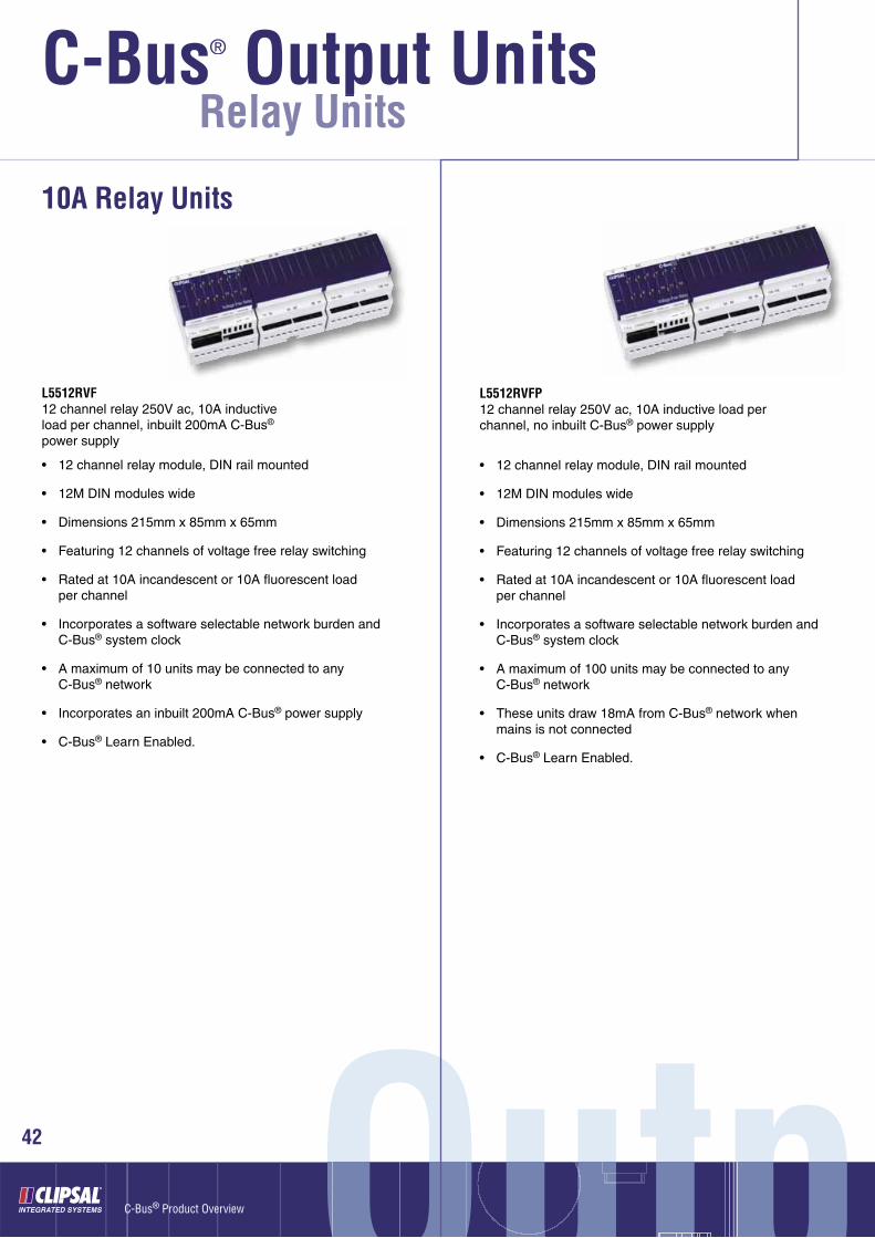
Relay Units
• 12 channel relay module, DIN rail mounted
• 12M DIN modules wide
• Dimensions 215mm x 85mm x 65mm
• Featuring 12 channels of voltage free relay switching
• Rated at 10A incandescent or 10A fl uorescent loadper channel
• Incorporates a software selectable network burden and C-Bus® system clock
• A maximum of 10 units may be connected to any C-Bus® network
• Incorporates an inbuilt 200mA C-Bus® power supply
• C-Bus® Learn Enabled.
10A Relay Units
L5512RVF12 channel relay 250V ac, 10A inductive load per channel, inbuilt 200mA C-Bus® power supply
• 12 channel relay module, DIN rail mounted
• 12M DIN modules wide
• Dimensions 215mm x 85mm x 65mm
• Featuring 12 channels of voltage free relay switching
• Rated at 10A incandescent or 10A fl uorescent load per channel
• Incorporates a software selectable network burden and C-Bus® system clock
• A maximum of 100 units may be connected to any C-Bus® network
• These units draw 18mA from C-Bus® network when mains is not connected
• C-Bus® Learn Enabled.
L5512RVFP12 channel relay 250V ac, 10A inductive load per channel, no inbuilt C-Bus® power supply
C-Bus® Output Unitsl U it
®

ut Unitsut Unitsnut UnnitsUnits43
• 4 channel relay module, DIN rail mounted
• 8M DIN modules wide
• Dimensions 144mm x 85mm x 65mm
• Featuring 4 channels of voltage free relay switching
• Rated at 10A incandescent or 10A fl uorescent load per channel
• Incorporates a software selectable network burden and C-Bus® system clock
• A maximum of 10 units may be connected to any C-Bus® network
• Incorporates an inbuilt 200mA C-Bus® power supply
• C-Bus® Learn Enabled.
• 4 channel relay module, DIN rail mounted
• 8M DIN modules wide
• Dimensions 144mm x 85mm x 65mm
• Featuring 4 channels of voltage free relay switching
• Rated at 10A incandescent or 10A fl uorescent load per channel
• Incorporates a software selectable network burden and C-Bus® system clock
• A maximum of 100 units may be connected to any C-Bus® network
• These units draw 18mA from C-Bus® when mains is not connected
• C-Bus® Learn Enabled.
L5504RVF4 channel relay 250V ac, 10A inductive load per channel, inbuilt 200mA C-Bus® power supply
L5504RVFP4 channel relay 250V ac, 10A inductive load per channel, no inbuilt C-Bus® power supply

C-Bus® Output Units®
OutpOutpu ptOutO44
C-Bus® Product Overview
Relay Units
• 4 channel changeover relay modules with interlock features, DIN rail mounted
• 8M DIN modules wide
• Dimensions 144mm x 85mm x 65mm
• Used for control of air conditioning systems (on/off, low, medium and high) and shutter or blind control (up/down)
• The unit can be simply wired to achieve electrical interlocking, for use where outputs are all mutually exclusive
• Relays rated at 10A resistive, 5A incandescent/inductive, 1A fl uorescent
• Incorporates a software selectable network burden and C-Bus® system clock
• A maximum of 100 units may be connected to any C-Bus® network
• These units draw 18mA from C-Bus® when mains is not connected
• C-Bus® Learn Enabled.
Changeover Relay Units
L5504RVFCP4 channel changeover relay, 250V ac, no inbuilt C-Bus® power supply, learn enabled
L5504RVFC4 channel changeover relay, 250V ac, learn enabled, inbuilt 200mA C-Bus® power supply, learn enabled
• Single channel relay unit for the control of motorised blinds, curtains or shutters via C-Bus®, DIN rail mounted
• 2M DIN modules wide
• Dimensions 36 x 85mm x 65mm
• Allows up/down and stop control
• A maximum of 100 units may be connected to a C-Bus® network
• Units draw 18mA from C-Bus® when mains is not connected
• C-Bus® Learn Enabled.
L5501RBCPC-Bus® Motorised Blinds/Curtains/Shutter Relay, 250 V ac, no C-Bus® Power Supply
Motorised Blinds/Curtains/Shutter Relay Unit
COMINGNEWNEWCOMING SOON

ut Unitsut Unitsnut UnnitsUnits45
20A Relay Units
• 4 channel 20A relay module, DIN rail mounted
• 12M DIN modules wide
• Dimensions 215mm x 85mm x 65mm
• 4 channels of voltage free relay switching
• Rated at 20A incandescent, 20A HID or 20A fl uorescent load per channel
• Relays features magnetic latching
• Built in mechanical level for manual changeover of relay state
• Incorporates a software selectable network burden and C-Bus® system clock
• A maximum of 10 units may be connected to any C-Bus® network
• Incorporates an inbuilt 200mA C-Bus® power supply
• C-Bus® Learn Enabled.
L5504RVF204 channel relay, 250V ac, 20A inductive load per channel, inbuilt 200mA C-Bus® power supply
• 4 channel 20A relay module, DIN rail mounted
• 12M DIN modules wide
• Dimensions 215mm x 85mm x 65mm
• 4 channels of voltage free relay switching
• Rated at 20A incandescent, 20A HID or 20A fl uorescent load per channel
• Relays feature magnetic latching
• Built in mechanical level for manual changeover of relay state
• Incorporates a software selectable network burden and C-Bus® system clock
• A maximum of 100 units may be connected to any C-Bus® network
• Units draw 18mA from the C-Bus® when mains is not connected
• C-Bus® Learn Enabled.
C-Bus® Output Units®
OutpOutpu ptOutO46
C-Bus® Product Overview
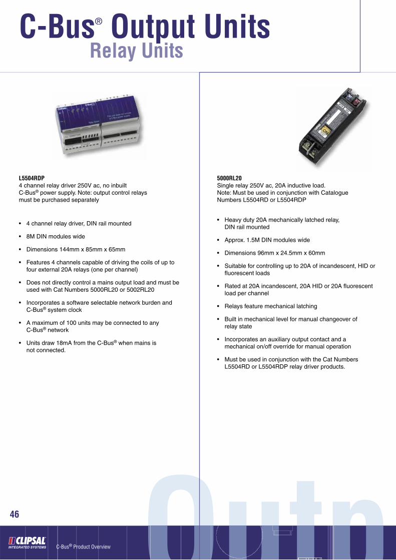
Relay Units
• Heavy duty 20A mechanically latched relay, DIN rail mounted
• Approx. 1.5M DIN modules wide
• Dimensions 96mm x 24.5mm x 60mm
• Suitable for controlling up to 20A of incandescent, HID or fl uorescent loads
• Rated at 20A incandescent, 20A HID or 20A fl uorescent load per channel
• Relays feature mechanical latching
• Built in mechanical level for manual changeover of relay state
• Incorporates an auxiliary output contact and a mechanical on/off override for manual operation
• Must be used in conjunction with the Cat Numbers L5504RD or L5504RDP relay driver products.
5000RL20Single relay 250V ac, 20A inductive load. Note: Must be used in conjunction with Catalogue Numbers L5504RD or L5504RDP
• 4 channel relay driver, DIN rail mounted
• 8M DIN modules wide
• Dimensions 144mm x 85mm x 65mm
• Features 4 channels capable of driving the coils of up to four external 20A relays (one per channel)
• Does not directly control a mains output load and must be used with Cat Numbers 5000RL20 or 5002RL20
• Incorporates a software selectable network burden and C-Bus® system clock
• A maximum of 100 units may be connected to any C-Bus® network
• Units draw 18mA from the C-Bus® when mains is not connected.
L5504RDP4 channel relay driver 250V ac, no inbuilt C-Bus® power supply. Note: output control relays must be purchased separately

ut Unitsut Unitsnut UnnitsUnits
• 2 x 20A magnetically latching relay module, DIN rail mounted
• 4M DIN modules wide
• Dimensions 72mm x 85mm x 65mm
• Must be used in conjunction with the C-Bus® L5504RD or L5504RDP relay driver products
• Compatible with 20A incandescent, inductive or fl uorescent loads
• Must be used in conjunction with the Cat Numbers L5504RD or L5504RDP relay driver products
• Incorporates mechanical overrides accessible by the user
• The mechanical lever is labelled with ON and OFF to indicate relay status.
5002RL20Dual relay 250V ac, 20A inductive load per relay. Note: Must be used in conjunction with Cat Numbers L5504RD or L5504RDP (see page 36)
• Single C-Bus® relay unit
• Dimensions 198mm x 42mm x 39mm
• Featuring 1 channel of 240V ac switching
• Suitable for incandescent, inductive and fl uorescent switching up to a maximum load of 10A
• A maximum of 100 units may be connected to any C-Bus® network
• These relays do not draw any current from C-Bus® network when mains power is connected.
Standard Relay Units
5101R1 channel relay 250V ac 10A inductive load
• 2 channel C-Bus® relay unit
• Dimensions 198mm x 42mm x 39mm
• Featuring 2 channels of 240V ac switching
• Suitable for incandescent, inductive and fl uorescent switching up to a maximum load of 10A per channel
• A maximum of 100 units may be connected to any C-Bus® network
• These relays do not draw any current from C-Bus® network when mains power is connected.
5102RVF2 channel voltage free relay 250 V ac, 10A inductive per channel
47
C-Bus® Product OverviewSuppoSuppouppppppSupuSSverviewee
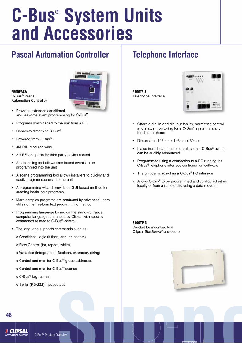
48 oooo
• Provides extended conditional and real-time event programming for C-Bus®
• Programs downloaded to the unit from a PC
• Connects directly to C-Bus®
• Powered from C-Bus®
• 4M DIN modules wide
• 2 x RS-232 ports for third party device control
• A scheduling tool allows time based events to be programmed into the unit
• A scene programming tool allows installers to quickly and easily program scenes into the unit
• A programming wizard provides a GUI based method for creating basic logic programs.
• More complex programs are produced by advanced users utilising the freeform text programming method
• Programming language based on the standard Pascal computer language, enhanced by Clipsal with specifi c commands related to C-Bus® control.
• The language supports commands such as:
o Conditional logic (if then, and, or, not etc)
o Flow Control (for, repeat, while)
o Variables (integer, real, Boolean, character, string)
o Control and monitor C-Bus® group addresses
o Control and monitor C-Bus® scenes
o C-Bus® tag names
o Serial (RS-232) input/output.
Pascal Automation Controller
5500PACAC-Bus® Pascal Automation Controller
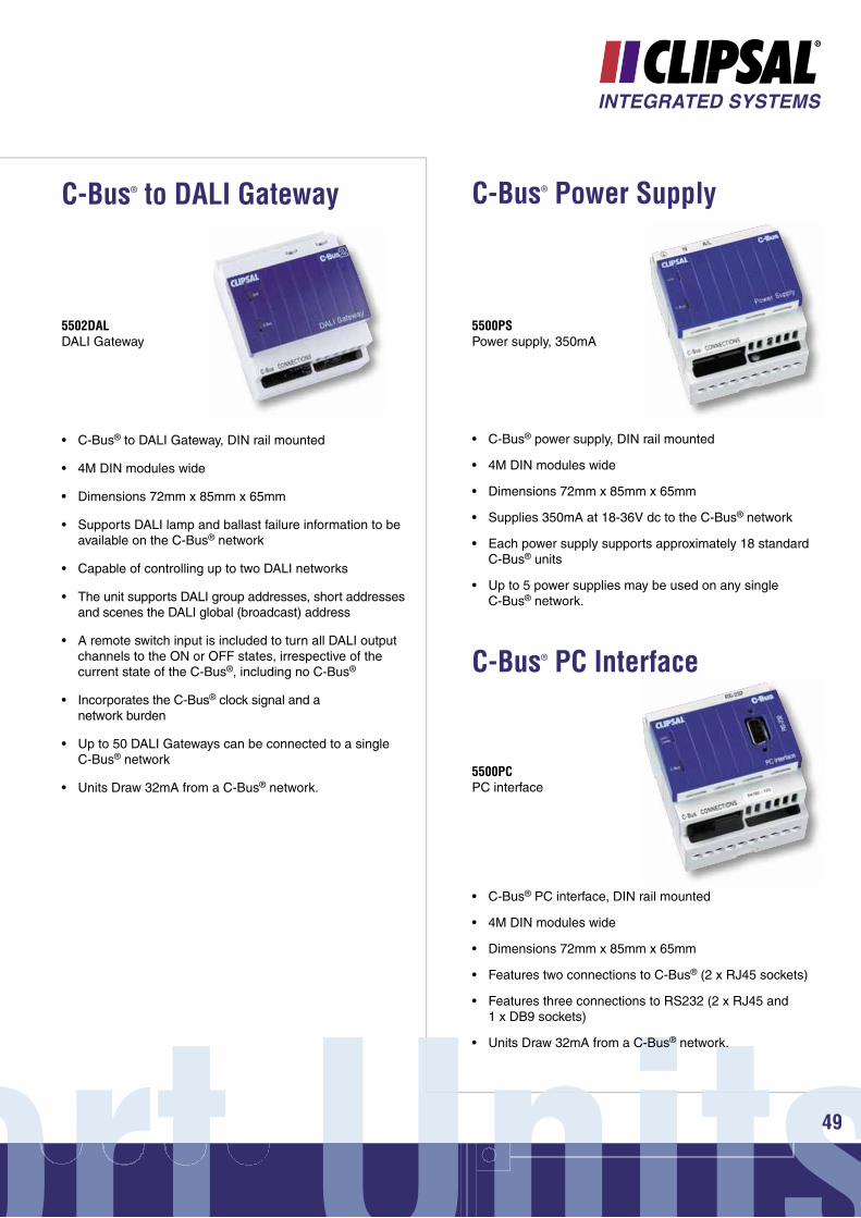
• Offers a dial in and dial out facility, permitting control and status monitoring for a C-Bus® system via any touchtone phone
• Dimensions 146mm x 146mm x 30mm
• It also includes an audio output, so that C-Bus® events can be audibly announced
• Programmed using a connection to a PC running the C-Bus® telephone interface confi guration software
• The unit can also act as a C-Bus® PC interface
• Allows C-Bus® to be programmed and confi gured either locally or from a remote site using a data modem.
Telephone Interface
5100TAUTelephone Interface
5100TMBBracket for mounting to a Clipsal StarServe® enclosure
C-Bus® System Units ®
and Accessories
ort Unitsort Unitsnort UnnitsUnits
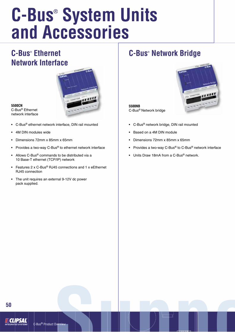
• C-Bus® to DALI Gateway, DIN rail mounted
• 4M DIN modules wide
• Dimensions 72mm x 85mm x 65mm
• Supports DALI lamp and ballast failure information to be available on the C-Bus® network
• Capable of controlling up to two DALI networks
• The unit supports DALI group addresses, short addresses and scenes the DALI global (broadcast) address
• A remote switch input is included to turn all DALI output channels to the ON or OFF states, irrespective of the current state of the C-Bus®, including no C-Bus®
• Incorporates the C-Bus® clock signal and a network burden
• Up to 50 DALI Gateways can be connected to a singleC-Bus® network
• Units Draw 32mA from a C-Bus® network.
C-Bus® to DALI Gateway
5502DALDALI Gateway
• C-Bus® power supply, DIN rail mounted
• 4M DIN modules wide
• Dimensions 72mm x 85mm x 65mm
• Supplies 350mA at 18-36V dc to the C-Bus® network
• Each power supply supports approximately 18 standard C-Bus® units
• Up to 5 power supplies may be used on any single C-Bus® network.
C-Bus® Power Supply
5500PSPower supply, 350mA
• C-Bus® PC interface, DIN rail mounted
• 4M DIN modules wide
• Dimensions 72mm x 85mm x 65mm
• Features two connections to C-Bus® (2 x RJ45 sockets)
• Features three connections to RS232 (2 x RJ45 and 1 x DB9 sockets)
• Units Draw 32mA from a C-Bus® network.
C-Bus® PC Interface
5500PCPC interface
49
C-Bus® Product Overview
50
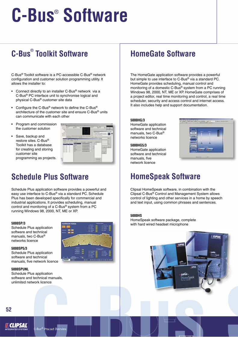
• C-Bus® ethernet network interface, DIN rail mounted
• 4M DIN modules wide
• Dimensions 72mm x 85mm x 65mm
• Provides a two-way C-Bus® to ethernet network interface
• Allows C-Bus® commands to be distributed via a 10 Base-T ethernet (TCP/IP) network
• Features 2 x C-Bus® RJ45 connections and 1 x eEthernet RJ45 connection
• The unit requires an external 9-12V dc power pack supplied.
C-Bus® Ethernet Network Interface
5500CNC-Bus® Ethernet network interface
• C-Bus® network bridge, DIN rail mounted
• Based on a 4M DIN module
• Dimensions 72mm x 85mm x 65mm
• Provides a two-way C-Bus® to C-Bus® network interface
• Units Draw 18mA from a C-Bus® network.
C-Bus® Network Bridge
5500NBC-Bus® Network bridge
SuppouppppppSupuSSvervieweeSuppoooo
C-Bus® System Units ®
and Accessories

• The Network Analyser is a tool used to measure various C-Bus® system parameters:
- Power Available- Clock Signal Present- Excess Voltage- Add/Remove Burden- Excess Cable Indication
• Dimensions 60.5mm x 120mm x 30.3mm
• Measures capacitance, burden, clock signal and network voltage
• The network analyser is powered from C-Bus® and is supplied with a pair of leads.
C-Bus® Network Analyser
5100NAC-Bus® network analyser
• 4 pair, Category 5, unshielded cable with a unique outer colour sheath specifi cally designed for the C-Bus® system
• A maximum of 1000 metres of cable is permitted on any one C-Bus® network
• Two pairs are used for the C-Bus® connection C-Bus® positive (blue + orange) and C-Bus® negative (blue/white+ orange/white)
• The C-Bus® cable must be segregated from the mains cable in C-Bus® installations
• C-Bus® cable has a mains rated outer sheath and Standard Cat 5 cable does not have this rating
• Suitable for use inside electrical enclosures.
C-Bus® Cable
5005C305BC-Bus® Category 5, 4 pair, UTP cable, 305 metres
ort Unitsort Unitsnort UnnitsU it
5100BCSBar code reader, USB connection, for use with C-Bus® Toolkit software
C-Bus® Barcode Reader
51
C-Bus® Product Overview
C-Bus® Software®
C-Bus SC-Bus SBusssssC-BusBCC-C-BusCC ® Product Overviewr ee®
52 SSSSS
C-Bus® Toolkit Software
Schedule Plus Software
The HomeGate application software provides a powerful but simple to use interface to C-Bus® via a standard PC. HomeGate provides scheduling, manual control and monitoring of a domestic C-Bus® system from a PC running Windows 98, 2000, NT, ME or XP. HomeGate comprises of a project editor, real time monitoring and control, a real time scheduler, security and access control and internet access. It also includes help and support documentation.
HomeGate Software
Clipsal HomeSpeak software, in combination with the Clipsal C-Bus® Control and Management System allows control of lighting and other services in a home by speech and text input, using common phrases and sentences.
HomeSpeak Software
5000HG/3HomeGate application software and technical manuals, two C-Bus® networks licence
5000HG5/3HomeGate application software and technical manuals, fi ve network licence
5000HSHomeSpeak software package, complete with hard wired headset microphone
Schedule Plus application software provides a powerful and easy use interface to C-Bus® via a standard PC. Schedule Plus has been developed specifi cally for commercial and industrial applications. It provides scheduling, manual control and monitoring of a C-Bus® system from a PC running Windows 98, 2000, NT, ME or XP.
5000SP/3Schedule Plus application software and technical manuals, two C-Bus® networks licence
5000SP5/3Schedule Plus application software and technical manuals, fi ve network licence
5000SPUNLSchedule Plus application software and technical manuals, unlimited network licence
C-Bus® Toolkit software is a PC-accessible C-Bus® network confi guration and customer solution programming utility. It allows the installer to:
• Connect directly to an installer C-Bus® network via a C-Bus® PC interface unit to synchronise logical and physical C-Bus® customer site data
• Confi gure the C-Bus® network to defi ne the C-Bus® architecture of the customer site and ensure C-Bus® units can communicate with each other
• Program and commission the customer solution
• Save, backup and restore sites. C-Bus® Toolkit has a database for creating and storing customer site programming as projects.
SoftwarewSoftwwarewware53
The Clipsal C-Gate® server is a software suite that monitors and controls the C-Bus® Control and Management System. It has been produced by Clipsal Integrated Systems to allow third party software developers and existing Building Management Systems to interface to C-Bus® at a high level, allowing high-speed control and monitoring of C-Bus®.
5000CGC-Gate® software package, single C-Bus® network licence
5000CG5C-Gate® software package, 5 C-Bus® network licence
5000CG10C-Gate® software package, 10 C-Bus® network licence
5000CG50C-Gate® software package, 50 C-Bus® network licence
5000CGUNLC-Gate software package, unlimited, C-Bus® network licence
C-Gate® Software
C-Lution® provides a complete solution for real time control and monitoring of Clipsal C-Bus® using clear and concise graphic images.
It provides a software platform on which a customisable, graphical Windows interface to a C-Bus® system can be built. Sophisticated animations can be created to display the operating status of the electrical services.
The package includes a driver library to interface with proprietary equipment such as Building Management Systems, PLCs, etc.
The Clipsal C-Lution® environment is primarily based on a Client/Server architecture, operable through TCP/IP network connections.
5000CL75C-Lution® software package, 75 points licence
5000CL150C-Lution® software package, 150 points licence
5000CL500C-Lution® software package, 500 points licence
5000CL1500C-Lution® software package, 1500 points licence
5000CL15KC-Lution® software package, 15,000 points licence
5000CLUNLC-Lution® software package, unlimited points licence
C-Lution® Software
C-Bus® Product Overview
C-Bus® Software®
C-Bus SC-Bus SBusssssC-BusBCC-C-BusCC ® Product Overviewr ee®
54 SSSSS
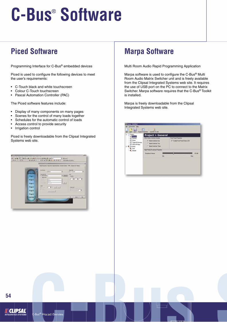
Piced Software
Programming Interface for C-Bus® embedded devices
Piced is used to confi gure the following devices to meetthe user’s requirements:
• C-Touch black and white touchscreen• Colour C-Touch touchscreen• Pascal Automation Controller (PAC)
The Piced software features include:
• Display of many components on many pages• Scenes for the control of many loads together• Schedules for the automatic control of loads• Access control to provide security• Irrigation control
Piced is freely downloadable from the Clipsal IntegratedSystems web site.
Marpa Software
Multi Room Audio Rapid Programming Application
Marpa software is used to confi gure the C-Bus® MultiRoom Audio Matrix Switcher unit and is freely availablefrom the Clipsal Integrated Systems web site. It requiresthe use of USB port on the PC to connect to the MatrixSwitcher. Marpa software requires that the C-Bus® Toolkit is installed.
Marpa is freely downloadable from the ClipsalIntegrated Systems web site.

SoftwarewSoftwwarewware55
Circa Software
C-Bus® Infrared Commissioning Software
Circa software is used to commission C-Bus® InfraredDevices (5034NIRT). The software allows the user toselect IR codes and assign them to particular outputchannels on an Infrared Device and make associationsbetween IR codes and C-Bus® events. The user can importIR device fi les created by the 5100RP Infrared Readerdevice. Circa software requires that C-Bus® InstallationSoftware V2 is installed.
Circa software is freely downloadable from the ClipsalIntegrated Systems web site.
Tica Software
Telephone Interface Commissioning Application
Tica software is used to confi gure the C-Bus® TelephoneInterface (CBTI). It requires the use of a RS232 serialport on the PC to connect to the CBTI. Tica softwarerequires that C-Bus Toolkit is installed.
Tica software is freely downloadable from the ClipsalIntegrated Systems web site.

C-Bus® Product Overview

Slimline™ Classic Eclipse® 2000 Neo®
Stainless Steel - SS
Chrome - CH
Gold - GD
Brushed Aluminium - BA
Brushed Brass - BB
Polished Brass - BS
Gunmetal -GM
Chrome Shadow -3S
Silver Plate - SP
Gold Plate - GP
Neo® Grey - GB
Neo® Brushed Aluminium* - BA
Neo® Gold* - GD
White - WE
Cream - CM
Soft Grey - SG
Desert Sand - DS
Black - BK
Brown - BR
Red - RD
Grey - GY
Beige - BG
Dove Grey - DO
Nutmeg - NU
* These colours only availble for the Inner Surround.Note: Silver and Gold Plate only available on surrounds of 2000 Series.
57
C-Bus® Product Overview
Multi-Room Audio System
58 Multi-roMulti-roti rrrru i-lMMMus® Product Overviewrr ee® ooooo
System Overview
The C-Bus® Multi-Room Audio System allows users to listen to and control audio sources from convenient locations around the home. The system is both simple to install and easy to use.
The system has been designed utilising new digital audio distribution technology (developed by Clipsal), in conjunction with Clipsal C-Bus® core technology for system communication and integration.
Clipsal’s digital audio distribution technology allows for noise and interference free audio reproduction, whilst the C-Bus® technology allows the audio products to be seamlessly integrated and used with all existing C-Bus® products. For example, volume can be controlled from the same C-Bus® switch or touch screen controlling lighting.
In addition, the system allows any input audio source to be made available in any audio zone. Changes to the input audio source can easily be made by the user from a local C-Bus® device at any time, regardless of where the audio source equipment (e.g., CD Player) is physically located. It is compatible with most audio sources and it accommodates standard stereo line level analogue inputs as well as digital audio TOS link inputs.
Infrared signals from hand held remote controls can be routed through the system by connecting IR targets and emitters. IR commands can also be stored by the system and activated by programmed C-Bus® commands.
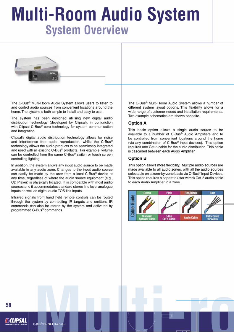
The C-Bus® Multi-Room Audio System allows a number of different system layout options. This fl exibility allows for a wide range of customer needs and installation requirements. Two example schematics are shown opposite.
Option A
This basic option allows a single audio source to be available to a number of C-Bus® Audio Amplifi ers and to be controlled from convenient locations around the home (via any combination of C-Bus® input devices). This option requires one Cat-5 cable for the audio distribution. This cable is cascaded between each Audio Amplifi er.
Option B
This option allows more fl exibility. Multiple audio sources are made available to all audio zones, with all the audio sources selectable on a zone-by-zone basis via C-Bus® Input Devices. This option requires a separate (star wired) Cat-5 audio cable to each Audio Amplifi er in a zone.

oom Audiooom AudioAom AudiAA dioNote 1
The C-Bus® Matrix Switcher is able to supply a limited amount of power to the Audio Amplifi ers, as the system shares power available via the Cat-5 audio network.
Note 2
Adding a power supply (5600P24/3750AU) to each amplifier will change the output power rating from 10W to 25W RMS.For further information on MRA power, please refer to http://www2.clipsal.com/cis/technical/technical_support/application_notes
Option A
Option B
‘See note 1 & 2 below’
59
C-Bus® Product Overview
Multi-Room Audio System
Multi-roMulti-roti rrrru i-lMMMus® Product Overviewrr ee®
60
Units and Accessories
ooooo
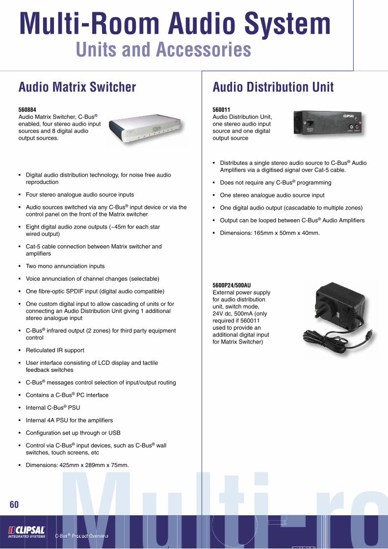
560884Audio Matrix Switcher, C-Bus® enabled, four stereo audio input sources and 8 digital audio output sources.
Audio Matrix Switcher
• Digital audio distribution technology, for noise free audio reproduction
• Four stereo analogue audio source inputs
• Audio sources switched via any C-Bus® input device or via the control panel on the front of the Matrix switcher
• Eight digital audio zone outputs (~45m for each star wired output)
• Cat-5 cable connection between Matrix switcher and amplifi ers
• Two mono annunciation inputs
• Voice annunciation of channel changes (selectable)
• One fi bre-optic SPDIF input (digital audio compatible)
• One custom digital input to allow cascading of units or for connecting an Audio Distribution Unit giving 1 additional stereo analogue input
• C-Bus® infrared output (2 zones) for third party equipment control
• Reticulated IR support
• User interface consisting of LCD display and tactile feedback switches
• C-Bus® messages control selection of input/output routing
• Contains a C-Bus® PC interface
• Internal C-Bus® PSU
• Internal 4A PSU for the amplifi ers
• Confi guration set up through or USB
• Control via C-Bus® input devices, such as C-Bus® wall switches, touch screens, etc
• Dimensions: 425mm x 289mm x 75mm.
560011Audio Distribution Unit, one stereo audio input source and one digital output source
Audio Distribution Unit
• Distributes a single stereo audio source to C-Bus® Audio Amplifi ers via a digitised signal over Cat-5 cable.
• Does not require any C-Bus® programming
• One stereo analogue audio source input
• One digital audio output (cascadable to multiple zones)
• Output can be looped between C-Bus® Audio Amplifi ers
• Dimensions: 165mm x 50mm x 40mm.
5600P24/500AUExternal power supply for audio distribution unit, switch mode, 24V dc, 500mA (only required if 560011 used to provide an additional digital input for Matrix Switcher)

oom Audiooom AudioAom AudiAA dio61
Audio Amplifi ers
560125R25 Watt/channel (RMS) stereo audio amplifi er, C-Bus® enabled, remote-mount version
• Used in conjunction with the C-Bus® Audio Matrix Switcher or the Audio Distribution Unit
• Controllable via C-Bus® input devices, such as C-Bus® wall switches and touch screens
• Volume, bass, treble, balance controlled by C-Bus® input devices
• Quiet digital audio design
• Stereo 25W RMS per channel – Remote and desktop mounted units (when power supply fi tted)
• Can be cascaded off one Digital Audio Cat 5 input
• Pre-amp output stage for connecting to a 3rd party power amplifi er
• Desktop Amplifi er includes power on/off, mute, volume and source select buttons and an infrared target for remote control. Also includes 3.5mm stereo head phone jack
• Set up via C-Bus® Toolkit software
• Signal source either:
o Distributed digital
o Locally connected line-level analogue
o Fibre-optic (TOSlink) SP/DIF (16bit, 48kHz)
• IR Target connection for reticulated IR support
• High effi ciency, ~70% at full power
• Dimensions (desktop): 181mm x 216mm x 75mm
• Dimensions (remote): 175mm x 209mm x 71mm.
560125D25 Watt/channel (RMS) stereo audio amplifi er, C-Bus® enabled, desktop-mount version
5600P24/3750AUExternal power supply for audio amplifi er, switch mode, 24V dc, 3.75A

C-Bus® Product Overview
Multi-Room Audio System
Multi-roMulti-roti rrrru i-lMMMus® Product Overviewrr ee®
62
Units and Accessories
ooooo
Audio Speakers
• Perfect for home theatre and multi-room audio applications
• Available with polypropylene or kevlar drivers, providing quality sound in all applications
• Flush mount design ensures only the front face of the speaker is visible and is fl ush with the wall/ceiling – inside of the wall/ceiling acts as the enclosure
• Provide great sound without loosing valuable fl oor space.
In-wall andIn-ceiling Speakers
5600IWPFlush mounted speakers (pair), rectangular, in-wall, polypropylene drivers
In-wall Speakers
5600IWKFlush mounted speakers (pair), rectangular, in-wall, kevlar drivers
• Sensitivity: <88dB (polypropylene), <91dB (kevlar)
• Frequency response: 50Hz – 20KHz (polypropylene), 49Hz – 20KHz (kevlar)
• Power output: 60W
• Impedance: 8 ohms
• Dimensions (Rim): 305mm x 220mm
• Colour: white.

oom Audiooom AudioAom AudiAA dio63
5600ICPFlush mounted speakers (pair), circular, in-ceiling, polypropylene drivers
In-ceiling Speakers
5600ICKFlush mounted speakers (pair), circular, in-ceiling, kevlar drivers
• Sensitivity: <90dB
• Frequency response: 45Hz – 20KHz
• Power output: 60W
• Impedance: 8 ohms
• Dimensions (rim diameter): 240mm
• Colour: white.
5600ODPOutdoor/shelf top speakers (pair), polypropylene drivers
Outdoor Speakers
• Designed to accurately reproduce high fi delity music in an outdoor environment
• Long lasting design incorporating rigid, high-impact plastic cabinets, polypropylene drivers, and powder coated metal grilles
• Sensitivity: <88dB
• Frequency response: 55Hz – 20KHz
• Power output: 35W
• Impedance: 8 ohms
• Colour: white and black
• Water resistant*.
*Clipsal outdoor speakers are not waterproof. Never install
outdoor speakers where they are directly hit by rain.
Under a porch, eave, or overhang provides a more
suitable environment.
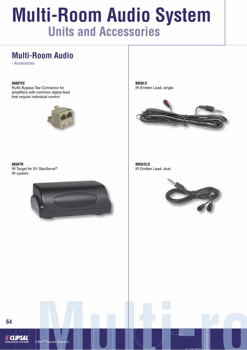
C-Bus® Product Overview
Multi-Room Audio System
Multi-roMulti-roti rrrru i-lMMMus® Product Overviewrr ee®
64
Units and Accessories
ooooo
Multi-Room Audio- Accessories
5600TEERJ45 Bypass Tee Connector for amplifi ers with common digital feed that require individual control
8050TRIR Target for 5V StarServe® IR system
8050LDIR Emitter Lead, single
8050/2LDIR Emitter Lead, dual

oom Audiooom AudioAom AudiAA dio65
8050STIR Shelf Target, with 1.8m cable
8050TTIR Tube Target, with 1.8m cable
8050FTIR Flat Target, with 1.8m cable

C-Bus® Product Overview
C-Bus® Wireless System®
SystemSystemstemmmmmys esSSyProduct Overviewrr e
66
(For Australia and New Zealand)
The C-Bus® Wireless product range incorporates a family of C-Bus® Radio Frequency (RF) devices, including Wall Plates, Plug Adaptors, Remote Control and a Gateway to Cat-5 wired C-Bus® units.
C-Bus® Wireless Wall Switches are designed to easily replace standard, 240V wall switches. They incorporate patented Clipsal technology and are two wire devices requiring no neutral (240V a.c. active and load connections only).
All C-Bus® Wireless units incorporate Clipsal C-Bus®’ unique Learn Mode functions for programming devices. Wall switches, Plug Adaptors and the Gateway Unit can also be programmed via the C-Bus® Toolkit software. Multiple C-Bus® Wireless units can be linked into a common network using Learn Mode or the C-Bus® Toolkit software.
Associations can be created between buttons on multiple units, so that a button pressed on one unit will operate a button on another (and the connected lights or other electrical devices).
C-Bus® Wireless units include scene capabilities, which allow the user to perform a series of actions across multiple outputs by pressing a single button. For example, on arrival home a home owner could use a scene to switch on lights in the hallway, kitchen and lounge, and also switch on a heater.
The diagrams below show two of the many possible basic C-Bus® Wireless unit installations. Room A uses stand-alone units, which can be switched via the Wireless Remote Control. Room B uses networked units where buttons on one unit can operate other units or trigger scenes.
Grouping C-Bus Wireless Units via Learn Mode
Programming a C-Bus® Wireless Unit via C-Bus® Toolkit software
Room A - Stand Alone C-Bus® Wireless Units
Room B -Networked C-Bus® Wireless Units
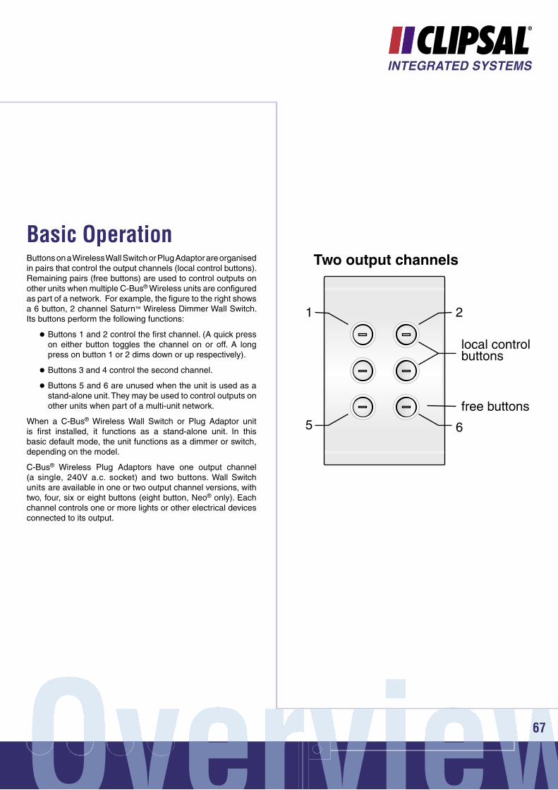
OverviewvOvervviewrr ie 67
Buttons on a Wireless Wall Switch or Plug Adaptor are organised in pairs that control the output channels (local control buttons). Remaining pairs (free buttons) are used to control outputs on other units when multiple C-Bus® Wireless units are confi gured as part of a network. For example, the fi gure to the right shows a 6 button, 2 channel Saturn™ Wireless Dimmer Wall Switch. Its buttons perform the following functions:
Buttons 1 and 2 control the fi rst channel. (A quick press on either button toggles the channel on or off. A long press on button 1 or 2 dims down or up respectively).
Buttons 3 and 4 control the second channel.
Buttons 5 and 6 are unused when the unit is used as a stand-alone unit. They may be used to control outputs on other units when part of a multi-unit network.
When a C-Bus® Wireless Wall Switch or Plug Adaptor unit is fi rst installed, it functions as a stand-alone unit. In this basic default mode, the unit functions as a dimmer or switch, depending on the model.
C-Bus® Wireless Plug Adaptors have one output channel (a single, 240V a.c. socket) and two buttons. Wall Switch units are available in one or two output channel versions, with two, four, six or eight buttons (eight button, Neo® only). Each channel controls one or more lights or other electrical devices connected to its output.
Basic Operation
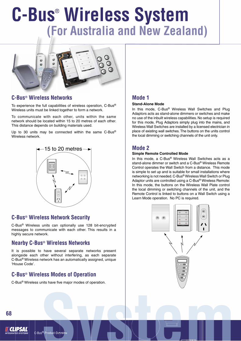
C-Bus® Product Overview
C-Bus® Wireless System®
SystemSystemstemmmmmys esSSyProduct Overviewrr e
68
(For Australia and New Zealand)
C-Bus® Wireless NetworksTo experience the full capabilities of wireless operation, C-Bus® Wireless units must be linked together to form a network.
To communicate with each other, units within the same network should be located within 15 to 20 metres of each other. This distance depends on building materials used.
Up to 30 units may be connected within the same C-Bus® Wireless network.
C-Bus® Wireless Network SecurityC-Bus® Wireless units can optionally use 128 bit-encrypted messages to communicate with each other. This results in a highly secure network.
Nearby C-Bus® Wireless NetworksIt is possible to have several separate networks present alongside each other without interfering, as each separate C-Bus® Wireless network has an automatically assigned, unique ‘House Code’.
C-Bus® Wireless Modes of OperationC-Bus® Wireless units have fi ve major modes of operation.
Mode 1Stand-Alone ModeIn this mode, C-Bus® Wireless Wall Switches and Plug Adaptors acts as stand-alone dimmers or switches and make no use of the inbuilt wireless capabilities. No setup is required for this mode, Plug Adaptors simply plug into the mains, and Wireless Wall Switches are installed by a licensed electrician in place of existing wall switches. The buttons on the units control the local dimming or switching channels of the unit only.
Mode 2Simple Remote Controlled ModeIn this mode, a C-Bus® Wireless Wall Switches acts as a stand-alone dimmer or switch and a C-Bus® Wireless Remote Control operates the Wall Switch from a distance. This mode is simple to set up and is suitable for small installations where networking is not needed. C-Bus® Wireless Wall Switch or Plug Adaptor units are controlled using a C-Bus® Wireless Remote: In this mode, the buttons on the Wireless Wall Plate control the local dimming or switching channels of the unit, and the Remote Control is linked to buttons on a Wall Switch using a Learn Mode operation. No PC is required.

OverviewvOvervviewrr ie 69
Mode 3Networked ModeIn this mode, a C-Bus® Wireless Wall Switch acts as a dimmer or switch and multiple C-Bus® Wireless units can be linked to each other with the C-Bus® Wireless technology. This mode is simple to setup, and is suitable for more complex installations. In this mode, local control buttons control the dimming or switch channel of the unit, and may also control other C-Bus® Wireless units. Free buttons can control the dimmer or switch channels of other units via a C-Bus® Wireless network established using Learn Mode operations. The operation of buttons is set using Learn Mode operations or using the C-Bus® Toolkit software.
Mode 4Networked with RemoteIn this mode, a C-Bus® Wireless Wall Switch acts as a dimmer or switch and multiple C-Bus® Wireless units can be linked to each other with the C-Bus® Wireless technology. Local control buttons control the dimming or switch channel of the unit, and may also control other C-Bus® Wireless units. Free buttons can control the dimmer or switch channels of other units via a C-Bus® Wireless network established using Learn Mode operations or C-Bus® Toolkit software. Buttons on the Wireless Remote are linked to Wall Switch and Plug Adaptor buttons as desired.
Mode 5Networked mode in combination with Cat-5 wired C-Bus® unitsThe C-Bus® Wireless Gateway is used to link a C-Bus® Wireless network to a C-Bus® Cat-5 wired network. It is functionally equivalent to a C-Bus® Network Bridge. Using the Gateway, C-Bus® Wireless and Cat-5 networks can communicate and interact with each other. Both Wireless and Cat-5 Network’s use the same command structure, and are 100% compatible.
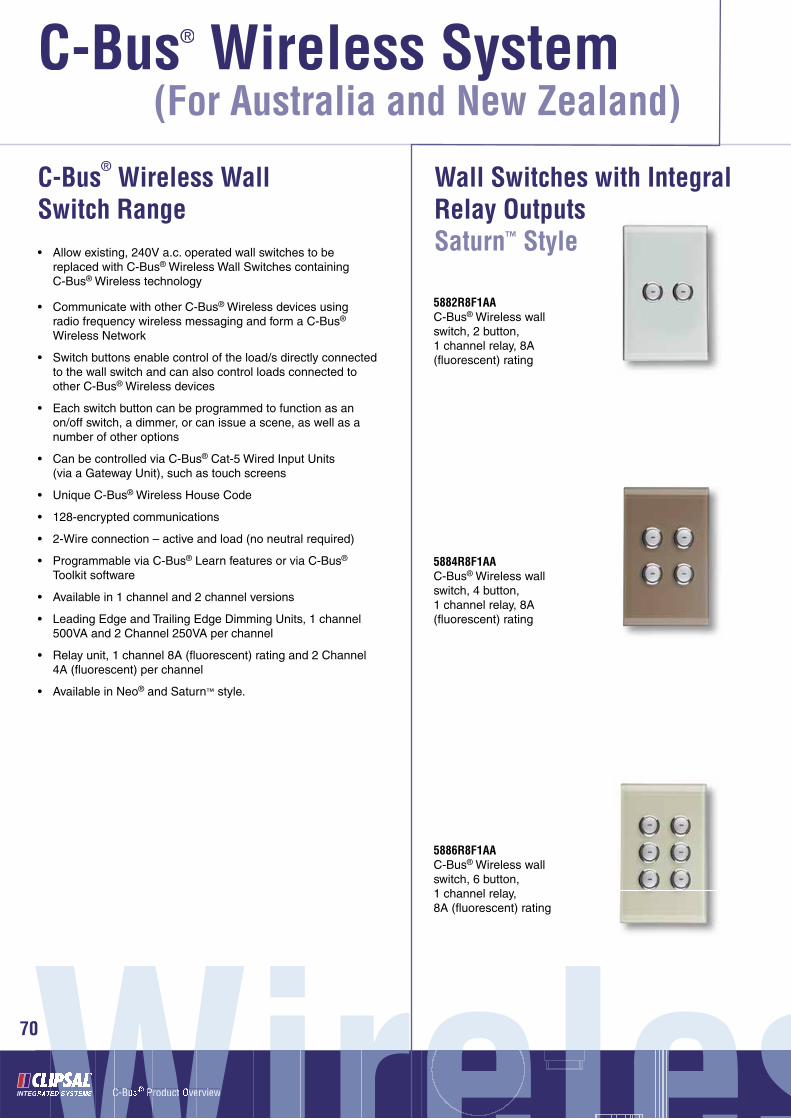
C-Bus® Product Overview
C-Bus® Wireless System®
70
(For Australia and New Zealand)
C-Bus® Wireless Wall Switch Range
5882R8F1AAC-Bus® Wireless wall switch, 2 button, 1 channel relay, 8A (fl uorescent) rating
5886R8F1AAC-Bus® Wireless wall switch, 6 button, 1 channel relay, 8A (fl uorescent) rating
• Allow existing, 240V a.c. operated wall switches to be replaced with C-Bus® Wireless Wall Switches containing C-Bus® Wireless technology
• Communicate with other C-Bus® Wireless devices using radio frequency wireless messaging and form a C-Bus® Wireless Network
• Switch buttons enable control of the load/s directly connected to the wall switch and can also control loads connected to other C-Bus® Wireless devices
• Each switch button can be programmed to function as an on/off switch, a dimmer, or can issue a scene, as well as a number of other options
• Can be controlled via C-Bus® Cat-5 Wired Input Units (via a Gateway Unit), such as touch screens
• Unique C-Bus® Wireless House Code
• 128-encrypted communications
• 2-Wire connection – active and load (no neutral required)
• Programmable via C-Bus® Learn features or via C-Bus® Toolkit software
• Available in 1 channel and 2 channel versions
• Leading Edge and Trailing Edge Dimming Units, 1 channel 500VA and 2 Channel 250VA per channel
• Relay unit, 1 channel 8A (fl uorescent) rating and 2 Channel 4A (fl uorescent) per channel
• Available in Neo® and Saturn™ style.
5884R8F1AAC-Bus® Wireless wall switch, 4 button, 1 channel relay, 8A (fl uorescent) rating
WirelesWirelese eeeeleWir lWWWWWWWWWWWWWWWWWWWWWWWWWWC-BuCC Product Overviewrr ee
0 sssss
Wall Switches with Integral Relay OutputsSaturn™ Style
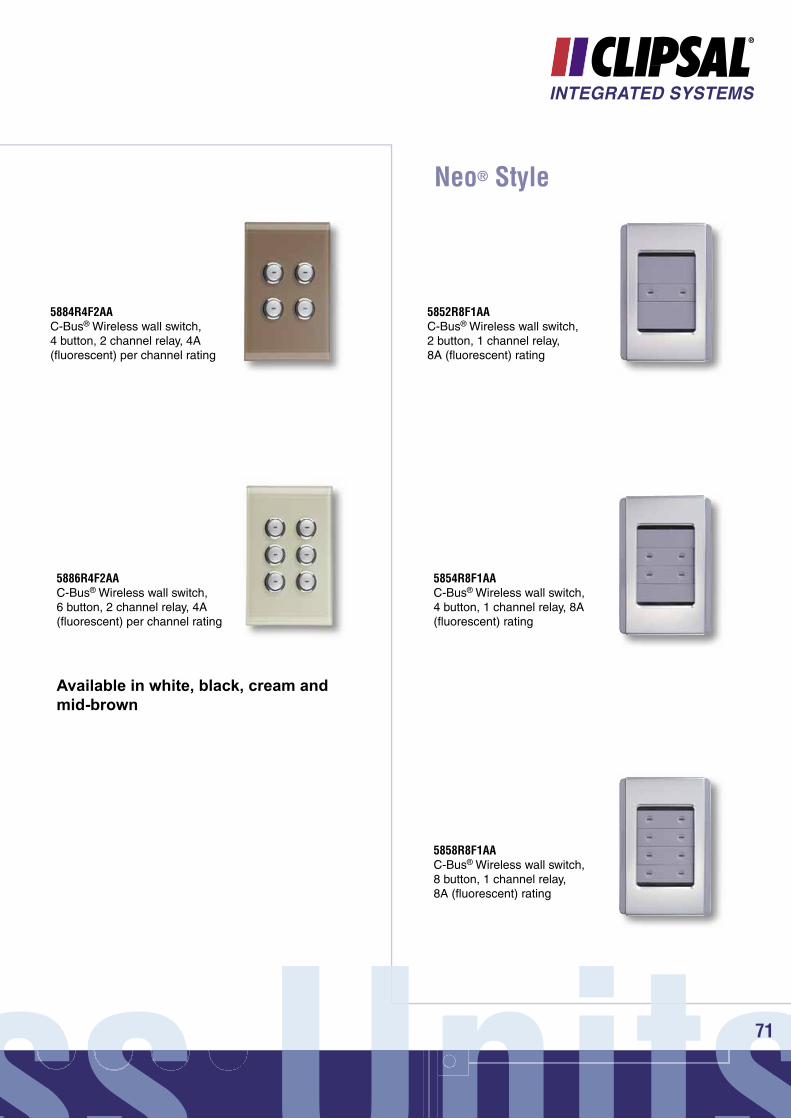
5884R4F2AAC-Bus® Wireless wall switch, 4 button, 2 channel relay, 4A (fl uorescent) per channel rating
5886R4F2AAC-Bus® Wireless wall switch, 6 button, 2 channel relay, 4A (fl uorescent) per channel rating
Available in white, black, cream and mid-brown
Neo® Style
5852R8F1AAC-Bus® Wireless wall switch, 2 button, 1 channel relay, 8A (fl uorescent) rating
5854R8F1AAC-Bus® Wireless wall switch, 4 button, 1 channel relay, 8A (fl uorescent) rating
5858R8F1AAC-Bus® Wireless wall switch, 8 button, 1 channel relay, 8A (fl uorescent) rating
ss Unitsss Unitsnss UnnitsU it 71

C-Bus® Product Overview
C-Bus® Wireless System®
72
(For Australia and New Zealand)
5854R4F2AAC-Bus® Wireless wall switch, 4 button, 2 channel relay, 4A (fl uorescent) per channel rating
Neo® Style
5858R4F2AAC-Bus® Wireless wall switch, 8 button, 2 channel relay, 4A (fl uorescent) per channel rating
Available in grey and silver, white electric,cream, desert sand, soft grey, black and brown
Wall Switches with Integral Leading Edge Dimmer Outputs
Saturn™ Style5882D2L1AAC-Bus® Wireless wall switch, 2 button, 1 channel leading edge dimmer, 500VA
5884D2L1AA C-Bus® Wireless wall switch, 4 button, 1 channel leading edge dimmer, 500VA
5886D2L1AA C-Bus® Wireless wall switch, 6 button, 1 channel leading edge dimmer, 500VA
WirelesWirelese eeeeleWir lWWWWWWWWWWWWWWWWWWWWWWWWWWC-BuCC Product Overviewrr ee
2 sssss

5884D1L2AAC-Bus® Wireless wall switch, 4 button, 2 channel leading edge dimmer, 250VA per channel
5886D1L2AAC-Bus® Wireless wall switch, 6 button, 2 channel leading edge dimmer, 250VA per channel
Available in white, black, cream and mid-brown
Neo® Style
5852D2L1AAC-Bus® Wireless wall switch, 2 button, 1 channel leading edge dimmer, 500VA
5858D2L1AAC-Bus® Wireless wall switch, 8 button, 1 channel leading edge dimmer, 500VA
5854D2L1AAC-Bus® Wireless wall switch, 4 button, 1 channel leading edge dimmer, 500VA
ss Unitsss Unitsnss UnnitsU it 73

C-Bus® Product Overview
C-Bus® Wireless System®
74
(For Australia and New Zealand)
WirelesWirelese eeeeleWir lWWWWWWWWWWWWWWWWWWWWWWWWWWC-BuCC Product Overviewrr ee
4 sssss
Wall Switches with Integral Trailing Edge Dimmer OutputsSaturn™ Style5854D1L2AA
C-Bus® Wireless wall switch, 4 button, 2 channel leading edge dimmer, 250VA per channel
Available in grey and silver, white electric, cream, desert sand, soft grey,black and brown
5858D1L2AAC-Bus® Wireless wall switch, 8 button, 2 channel leading edge dimmer, 250VA per channel
Neo® Style
5882D2T1AAC-Bus® Wireless wall switch, 2 button, 1 channel trailing edge dimmer, 500VA
5884D2T1AAC-Bus® Wireless wall switch, 4 button, 1 channel trailing edge dimmer, 500VA
5886D2T1AAC-Bus® Wireless wall switch, 6 button, 1 channel trailing edge dimmer, 500VA

75ss Unitsss Unitsnss UnnitsU it 7575
5884D1T2AAC-Bus® Wireless wall switch, 4 button, 2 channel trailing edge dimmer, 250VA per channel
Available in white, black, cream and mid-brown
5886D1T2AAC-Bus® Wireless wall switch, 6 button, 2 channel trailing edge dimmer, 250VA per channel
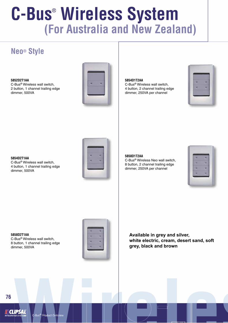
C-Bus® Product Overview
C-Bus® Wireless System®
76
(For Australia and New Zealand)
Neo® Style
5852D2T1AAC-Bus® Wireless wall switch, 2 button, 1 channel trailing edge dimmer, 500VA
5854D2T1AAC-Bus® Wireless wall switch, 4 button, 1 channel trailing edge dimmer, 500VA
5858D2T1AAC-Bus® Wireless wall switch, 8 button, 1 channel trailing edge dimmer, 500VA
5854D1T2AAC-Bus® Wireless wall switch, 4 button, 2 channel trailing edge dimmer, 250VA per channel
5858D1T2AAC-Bus® Wireless Neo wall switch, 8 button, 2 channel trailing edge dimmer, 250VA per channel
Available in grey and silver, white electric, cream, desert sand, soft grey, black and brown
WirelesWirelese eeeelWirelrWWWWWWWWWWWWWWWWWWWWWWC-BusC ® Product Overviewr e® sssss

77
Saturn™ - Pre-labelled Button Caps
5080LC-8Pre-labelled button caps individually printed with commonly used labels (pack of 66)
Saturn™ - Glass Facias Rectangular Series
508xF,GFGlass facia only, rectangular, white
508xF-30Glass facia only, rectangular, cream
508xF-60Glass facia only, rectangular, black
508xF-70Glass facia only, rectangular, mid-brown
‘x’ denotes number of buttons i.e. 2, 4 or 6 buttonss Unitsss Unitsnss UnnitsU it 7777‘x’ denotes number of buttons i.e. 2, 4 or 6 button‘x’ denotes number of buttons i.e. 2, 4 or 6 but

C-Bus® Product Overview
C-Bus® Wireless System®
78
(For Australia and New Zealand)
WirelesWirelese eeeeleWir lWWWWWWWWWWWWWWWWWWWWWWWWWWC-BuCC Product Overviewrr ee
8 sssss
Saturn™ - Mounting Frames Rectangular Series
5850F,BKMounting frame, rectangular, black (pack of 5)
5850F,BRMounting frame, rectangular, brown (pack of 5)
5850F,CMMounting frame, rectangular, cream (pack of 5)
5850F,DSMounting frame, rectangular, desert sand (pack of 5)
5850F,SGMounting frame, rectangular, soft grey (pack of 5)
5850F,WEMounting frame, rectangular, white (pack of 5)

ss Unitsss Unitsnss UnnitsU it 79
Saturn™ - Mounting Spacer Rectangular Series
5080SD,BKMounting spacer, rectangular, black (pack of 5)
5080SD,CMMounting spacer, rectangular, brown (pack of 5)
5050SD,CMMounting spacer, rectangular
Available in the following colours
White
Black
Brown
Cream
Desert Sand
Soft Grey
Available in the following colours
White
Black
Brown
Cream
Desert Sand
Soft Grey
Neo™ - Mounting Spacer Rectangular Series
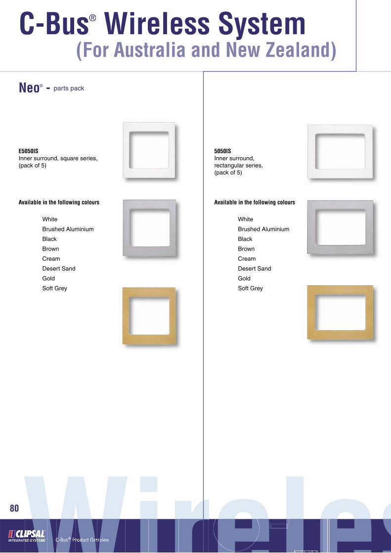
C-Bus® Product Overview
C-Bus® Wireless System®
80
(For Australia and New Zealand)
WirelesWirelese eeeelWirelrWWWWWWWWWWWWWWWWWWWWWWC-BusC ® Product Overviewr e® sssss
E5050ISInner surround, square series,(pack of 5)
5050ISInner surround, rectangular series, (pack of 5)
Neo® - parts pack
Available in the following colours
White
Brushed Aluminium
Black
Brown
Cream
Desert Sand
Gold
Soft Grey
Available in the following colours
White
Brushed Aluminium
Black
Brown
Cream
Desert Sand
Gold
Soft Grey

ss Unitsss Unitsnss UnnitsU it 81
E5050OSOuter surround, square, (pack of 5)
5050OSOuter surround, rectangular series, (pack of 5)
5052NRPRocker covers and spacers for E5052NL and 5052NL series, (pack of 5 rocker switch covers and 10 spacers)
Available in the following colours
White
Black
Brown
Cream
Desert Sand
Soft Grey
Battleship Grey
Available in the following colours
White
Black
Brown
Cream
Desert Sand
Soft Grey
Battleship Grey
Available in the following colours
White
Black
Brown
Cream
Desert Sand
Soft Grey
Battleship Grey
5054NRPRocker covers and spacers for E5054NL and 5054NL series, (pack of 10 rocker switch covers and 10 spacers)
5058NRPRocker covers for E5058NL and 5058NL series, (pack of 20)

C-Bus® Product Overview
C-Bus® Wireless System®
82
(For Australia and New Zealand)
C-Bus® Wireless Plug Adaptors• Allow devices normally plugged into 240V a.c. general
purpose outlets (for example, lounge or bedside lamps) to be controlled using C-Bus® Wireless technology
• Communicate with other C-Bus® Wireless devices (such as Wireless Wall Switches) using radio frequency wireless messaging and form a C-Bus® Wireless Network
• C-Bus® Wireless Plug Adaptors plug into existing power outlets, and the device to be controlled via C-Bus® Wireless then piggybacks into the Plug Adaptor. No additions or alterations to existing wiring are required
• Plug into a Standard Australian and New Zealand general purpose electrical outlet
• Available in Leading Edge Dimming and Trailing Edge Dimming Units, as well as a Relay output version
• Integral, easily accessible control/override/programming buttons
• Can be controlled via C-Bus® Cat-5 wired Input units (via a Gateway Unit), such as touch screens
• Unique C-Bus® Wireless House Code
• 128-encrypted communications
• Programmable via C-Bus® Learn features or via C-Bus® Toolkit software.
Dimmers
5812D3L1AAC-Bus® Wireless plug adaptor, 1 channel leading edge dimmer, 3A
5812D2T1AAC-Bus® Wireless plug adaptor, 1 channel trailing edge dimmer, 2A
WirelesWirelese eeeelWirelrWWWWWWWWWWWWWWWWWWWWWWC-BusC ® Product Overviewr e® sssss

Relay
5812R10F1AAC-Bus® Wireless plug adaptor, 1 channel relay, 10A
5080TXCC-Bus® Remote Control Holder (spare)
5888TXBAC-Bus® Wireless hand-held remote control unit with holder
C-Bus® Wireless Remote Control Unit
• Allows control of buttons on C-Bus® Wireless Wall Switch and Plug Adaptor units remotely
• Utilises radio frequency (RF) communication
• Does not need to be pointed directly at the unit being controlled
• Capable of controlling up to 10 separate Wall Switch or Plug Adaptor buttons
• A single button on a Wall Switch or Plug Adaptor can be controlled by up to two C-Bus® Wireless Remote Controls
• Buttons are organised in two banks of fi ve buttons. Banks are alternately selected by pressing the ‘Shift’ button
• Up and Down buttons allow dimming of the level associated with the last button selected (on dimmer units)
• ‘All Off’ button provides a convenient way to switch off all buttons associated with the remote control unit
• C-Bus® Wireless Groups and Scenes can be controlled from the remote
• LCD screen and buttons incorporate a blue LED backlight
• Each control button incorporates a clear window for button labelling
• Supplied with pre-labelled stickers for identifi cation of common areas i.e. kitchen, lounge, dining etc
• 20-25m range (typical).
ss Unitsss Unitsnss UnnitsU it 83
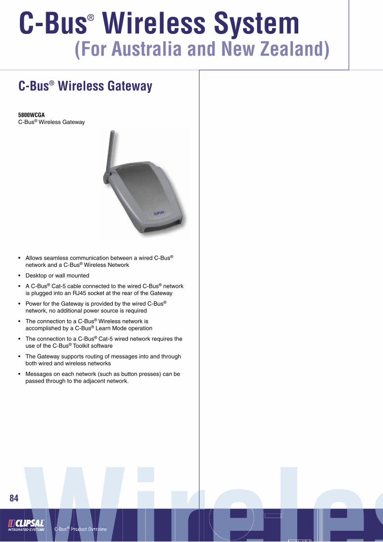
C-Bus® Product Overview
C-Bus® Wireless System®
84
(For Australia and New Zealand)
C-Bus® Wireless Gateway
• Allows seamless communication between a wired C-Bus® network and a C-Bus® Wireless Network
• Desktop or wall mounted
• A C-Bus® Cat-5 cable connected to the wired C-Bus® network is plugged into an RJ45 socket at the rear of the Gateway
• Power for the Gateway is provided by the wired C-Bus® network, no additional power source is required
• The connection to a C-Bus® Wireless network is accomplished by a C-Bus® Learn Mode operation
• The connection to a C-Bus® Cat-5 wired network requires the use of the C-Bus® Toolkit software
• The Gateway supports routing of messages into and through both wired and wireless networks
• Messages on each network (such as button presses) can be passed through to the adjacent network.
5800WCGAC-Bus® Wireless Gateway
WirelesWirelese eeeelWirelrWWWWWWWWWWWWWWWWWWWWWWC-BusC ® Product Overviewr e® sssss

Notes
ss Unitsss Unitsnss UnnitsU it 85
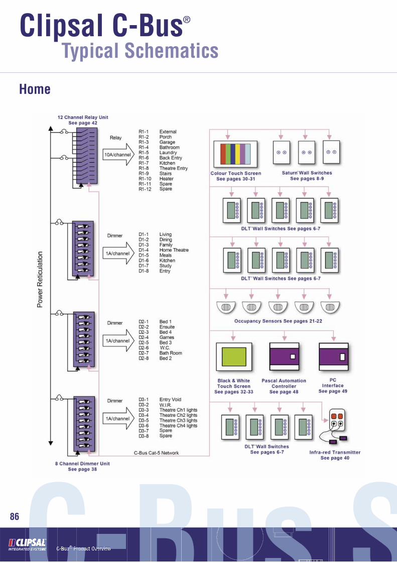
C-Bus® Product OverviewC-Bus SusC B suCC-CCCCCCCCCCCCCsC ® Product Overviewrr ee®C-Bus SSSSS86
Clipsal C-Bus®
Typical Schematics
Home

SchematiSchematimchemmatm 87
Commercial High Rise Building

clipsal.com/cis
Product of Clipsal Integrated Sys temsA division of Clipsal Australia Pty LtdABN 27 007 873 529
Head Offi ce12 Park Terrace, BowdenSouth Australia 5007
PO Box 103 HindmarshSouth Australia 5007Telephone (08) 8345 9500International +61 8 8345 9500
Facsimile (08) 8346 0845International +61 8 8346 0845
Internet www.clipsal.com/cisE-Mail [email protected]
CIS Technical Support Hotline:1300 722 247
National Customer Service Enquiries:1300 2025 25
National Customer Service Facsimile:1300 2025 56
International Enquiries
International Sales and MarketingTelephone +61 8 8269 0587Facsimile +61 8 8340 7350E-Mail [email protected]
New ZealandClipsal Industries (NZ) LtdTelephone +64 9 576 3403Facsimile +64 9 576 1015E-Mail headoffi [email protected]
Customer ServiceFree Facsimile (0508) 250 305Auckland/Mobile Phone (09) 572 0014Free Phone (0508) CLIPSAL 2547725
MalaysiaClipsal Integrated Systems (M) Sdn BhdUnit 3-2, Level 3, C P TowerNo.11, Jalan 16/11, Seksyen 16,46350 Petaling Jaya, Selangor, MalaysiaTelephone +60 3 7665 3555Facsimile +60 3 7665 3155E-Mail [email protected]
SingaporeClipsal Integrated Systems Pte Ltd5, Fourth Chin Bee Road619 699 SingaporeTelephone +65 6415 3232/3233Facsimile +65 6415 3289E-Mail [email protected]
Clipsal Australia Pty Ltd reserves the right to change spec i fi ca tions, modify designs and dis con tin ue items without incurring obligation and whilst every effort is made to ensure that descriptions, specifi cations and other in for ma tion in this catalogue are correct, no warranty is given in respect thereof and the company shall not be liable for any error therein.
You can fi nd this brochure and many others online in PDF format at: clipsal.comFollow the links off the home page or access the following page directly: clipsal.com/wat_lib_pdf.cfm
© Clipsal Australia Pty Ltd 2006.All rights reserved.
This material is copyright under Australian and international laws. Except as permitted under the relevant law, no part of this work may be reproduced by any process without prior written permission of and acknowledgement to Clipsal Australia Pty Ltd.
International Representatives
ChinaClipsal China LimitedTelephone +86 755 8237 5959
GreeceSchneider Electric AETelephone +30 69 4646 3200
Hong KongClipsal Integrated Systems (HK) LimitedTelephone +852 2487 0261
IndiaSchneider Electric India Pvt Ltd Telephone +91 11 5159 0000
IndonesiaPT Clipsal Graha NusaTelephone +62 21 630 6430
KoreaClipsal Korea Co. LtdTelephone +822 549 5550
PakistanClipsal Pakistan (Pvt) LtdTelephone +92 21 506 7278
PhilippinesClipsal Philippines Inc.Telephone +632 683 0275-78
South AfricaClipsal South Africa (Pty) LtdTelephone +27 11 314 5200
TaiwanClipsal (Taiwan) Co LtdTelephone +886 2 2558 3456
ThailandClipsal Thailand LtdTelephone +66 2 952 5338-42
United Arab EmiratesClipsal Middle EastTelephone +971 6 5570 777
United KingdomClipsal Integrated SystemsC/o Schneider ElectricTelephone +44 870 608 8 608
VietnamClipsal - VTECTelephone +848 856 3002 IS
1-00
6
O/N 5902CLIPCOM 11494 Aug 2006

![Cold Chisel To Rock The 2015 Clipsal 500 Adelaide [2015 Clipsal]](https://static.fdocuments.net/doc/165x107/55c37b9ebb61eb6b5e8b469a/cold-chisel-to-rock-the-2015-clipsal-500-adelaide-2015-clipsal.jpg)


![Cold Chisel To Rock The 2015 Clipsal 500 Adelaide [Adelaide Clipsal 2015 Live]](https://static.fdocuments.net/doc/165x107/55cc7d46bb61ebff138b461d/cold-chisel-to-rock-the-2015-clipsal-500-adelaide-adelaide-clipsal-2015-live.jpg)


![2012 Race 1 V8 Supercars Clipsal 500 Adelaide [Adelaide Clipsal]](https://static.fdocuments.net/doc/165x107/55c65bb9bb61eb884d8b482a/2012-race-1-v8-supercars-clipsal-500-adelaide-adelaide-clipsal.jpg)


![Cold Chisel To Rock The 2015 Clipsal 500 Adelaide [2015 Clipsal 500]](https://static.fdocuments.net/doc/165x107/58edabcf1a28aba4088b4607/cold-chisel-to-rock-the-2015-clipsal-500-adelaide-2015-clipsal-500.jpg)