Clinton, Unit 1, Additional Information Regarding Relief ...
42
4300 Winfield Road Warrenvill.e. 1 630555 630 657 2000 Office 10 CFR 50.55a Exelon Generation:. RS-13-052 February 8, 2013 U.S. Nuclear Regulatory Commission ATTN: Document Control Desk Washington, DC 20555-0001 Clinton Power Station, Unit 1 Facility Operating License No. NPF-62 NRC Docket No. 50-461 Subject: Additional Information Regarding Relief Request 13R-09, Alternative to VT-2 Visual Inspection of Combustible Gas Control System Piping References: 1. Letter from D. M. Gullott (Exelon Generation Company, LLC) to U. S. NRC, "Relief Request Associated with the Third Inservice Inspection Interval," dated August 23, 2012 2. Letter from J. S. Wiebe (U.S. NRC) to M. J. Pacilio (Exelon Generation Company, LLC), "Clinton Power Station, Unit No.1 - Request For Additional Information Regarding Relief Request 13R-09, Alternative to VT-2 Visual Inspection of Combustible Gas Control System Piping (TAC NO. ME9428)," dated January 29, 2013 In Reference 1, Exelon Generation Company, LLC (EGC) requested NRC approval of a relief request associated with the third 10-year inservice testing (IST) program interval for Clinton Power Station (CPS). Specifically, Reference 1 requested approval of an alternative to the performance of VT-2 visual inspections for Combustible Gas Control system piping. In Reference 2, the NRC requested additional information that is needed to complete review of relief request 13R-09. In response to this request, EGC is providing the attached information. There are no regulatory commitments contained in this letter. Should you have any questions concerning this letter, please contact Mr. Thomas J. Griffith at (630) 657-2818. Exelon Generation RS-13-052 February 8, 2013 U.S. Nuclear Regulatory Commission ATTN: Document Control Desk Washington, DC 20555-0001 Clinton Power Station, Unit 1 Facility Operating License No. NPF-62 NRC Docket No. 50-461 4300 Winfield Road Warrenvllle.IL 60555 630 657 2000 Office 10 CFR 50.55a Subject: Additional Information Regarding Relief Request 13R-09, Alternative to VT-2 Visual Inspection of Combustible Gas Control System Piping References: 1. Letter from D. M. Gullott (Exelon Generation Company, LLC) to U.S. NRC. "Relief Request Associated with the Third Inservice Inspection Interval," dated August 23. 2012 2. Letter from J. S. Wiebe (U.S. NRC) to M. J. Pacilio (Exelon Generation Company, LLC). "Clinton Power Station, Unit No.1 - Request For Additional Information Regarding Relief Request 13R-09, Alternative to VT-2 Visual Inspection of Combustible Gas Control System Piping (TAC NO. ME9428)," dated January 29, 2013 In Reference 1. Exelon Generation Company, LLC (EGC) requested NRC approval of a relief request associated with the third 10-year inservice testing (1ST) program interval for Clinton Power Station (CPS). Specifically, Reference 1 requested approval of an alternative to the performance of VT -2 visual inspections for Combustible Gas Control system piping. In Reference 2, the NRC requested additional information that is needed to complete review of relief request 13R-09. In response to this request, EGC is providing the attached information. There are no regulatory commitments contained in this letter. Should you have any questions concerning this letter, please contact Mr. Thomas J. Griffith at (630) 657-2818. r<.. Patrick R. impson Manager - Licensing
Transcript of Clinton, Unit 1, Additional Information Regarding Relief ...
4300 Winfield RoadWarrenvill.e. 1 630555
630 657 2000 Office
10 CFR 50.55a
Exelon Generation:.
RS-13-052
February 8, 2013
U.S. Nuclear Regulatory CommissionATTN: Document Control DeskWashington, DC 20555-0001
Clinton Power Station, Unit 1Facility Operating License No. NPF-62NRC Docket No. 50-461
Subject:
Additional Information Regarding Relief Request 13R-09, Alternative to VT-2Visual Inspection of Combustible Gas Control System Piping
References: 1. Letter from D. M. Gullott (Exelon Generation Company, LLC) to U. S. NRC,"Relief Request Associated with the Third Inservice Inspection Interval,"dated August 23, 2012
2. Letter from J. S. Wiebe (U.S. NRC) to M. J. Pacilio (Exelon Generation
Company, LLC), "Clinton Power Station, Unit No.1 - Request For Additional
Information Regarding Relief Request 13R-09, Alternative to VT-2 VisualInspection of Combustible Gas Control System Piping (TAC NO. ME9428),"dated January 29, 2013
In Reference 1, Exelon Generation Company, LLC (EGC) requested NRC approval of a reliefrequest associated with the third 10-year inservice testing (IST) program interval for ClintonPower Station (CPS). Specifically, Reference 1 requested approval of an alternative to theperformance of VT-2 visual inspections for Combustible Gas Control system piping.In Reference 2, the NRC requested additional information that is needed to complete review ofrelief request 13R-09. In response to this request, EGC is providing the attached information.
There are no regulatory commitments contained in this letter. Should you have any questionsconcerning this letter, please contact Mr. Thomas J. Griffith at (630) 657-2818.
Exelon Generation
RS-13-052
February 8, 2013
U.S. Nuclear Regulatory Commission ATTN: Document Control Desk Washington, DC 20555-0001
Clinton Power Station, Unit 1 Facility Operating License No. NPF-62 NRC Docket No. 50-461
4300 Winfield Road Warrenvllle.IL 60555
630 657 2000 Office
10 CFR 50.55a
Subject: Additional Information Regarding Relief Request 13R-09, Alternative to VT-2 Visual I nspection of Combustible Gas Control System Piping
References: 1. Letter from D. M. Gullott (Exelon Generation Company, LLC) to U.S. NRC. "Relief Request Associated with the Third Inservice Inspection Interval," dated August 23. 2012
2. Letter from J. S. Wiebe (U.S. NRC) to M. J. Pacilio (Exelon Generation Company, LLC). "Clinton Power Station, Unit No.1 - Request For Additional Information Regarding Relief Request 13R-09, Alternative to VT-2 Visual Inspection of Combustible Gas Control System Piping (TAC NO. ME9428)," dated January 29, 2013
In Reference 1. Exelon Generation Company, LLC (EGC) requested NRC approval of a relief request associated with the third 10-year inservice testing (1ST) program interval for Clinton Power Station (CPS). Specifically, Reference 1 requested approval of an alternative to the performance of VT -2 visual inspections for Combustible Gas Control system piping. In Reference 2, the NRC requested additional information that is needed to complete review of relief request 13R-09. In response to this request, EGC is providing the attached information.
There are no regulatory commitments contained in this letter. Should you have any questions concerning this letter, please contact Mr. Thomas J. Griffith at (630) 657-2818.
r<.. Patrick R. impson Manager - Licensing

February 8, 2013U.S. Nuclear Regulatory CommissionPage 2
Attachments:
1. Response to Request for Additional Information2. Referenced Procedure
cc:
NRC Regional Administrator, Region IIINRC Senior Resident Inspector, Clinton Power Station
February 8, 2013 U.S. Nuclear Regulatory Commission Page 2
Attachments:
1. Response to Request for Additional Information 2. Referenced Procedure
cc; NRC Regional Administrator, Region '" NRC Senior Resident Inspector, Clinton Power Station

Attachment 1Response to Request for Additional Information
Attachment 1 Response to Request for Additional Information

Attachment 1Response to Request for Additional Information
NRC Request 1
When is the scheduled end of the CPS third 10-year inservice inspection interval?
Response
The third 10-year inservice inspection interval, at Clinton Power Station, is currently scheduledto end on June 30, 2020.
NRC Request 2
The column "Pressure Drop Test Duration" in the Table of the proposed alternative might implythat the LLRT is a pressure decay test. Is the LLRT a flow test or is it a pressure decay test?Provide a brief description of the LLRT surveillance procedure CPS 9861.02.
Response
This test is a flow test and, as described in CPS 9861.02, there are three 'test sets' for eachtrain of the hydrogen recombiner subsystems (i.e., train 'A' and train 'B') in the Combustible GasControl (HG) system. The three test sets for each of the respective subsystems are as follows:
Test set A, for the 'A' Hydrogen Recombiner train, tests piping and components on theinlet line from the open-ended piping in the containment to motor-operated containmentisolation valve 1 HGOO1.
Test set A, for the'B' Hydrogen Recombiner train, tests piping and components on theoutlet line from the open-ended piping in the containment to motor-operated containmentisolation valve 1 HG008.
• Test set B, for the 'A' train, tests piping and components on the outlet line from motor -operated containment isolation valve 1 HGO04 to the open-ended piping in thecontainment.
• Test set B, for the 'B' train, tests piping and components on the inlet line from motor -operated containment isolation valve 1 HGO05 to the open-ended piping in thecontainment.
• Test set C for both trains tests piping and components on the inlet and outlet lines fromthe open-ended inlet piping in the containment, through the respective hydrogenrecombiner (i.e., OHGO1 SA or OHGO1 SB) to the open-ended outlet piping in thecontainment, respectively.
Test procedure 9861.02 (i.e., CPS 9861.02D033 and CPS 9861.02D041) is included, asAttachment 2, to this letter.
Page 1
Attachment 1 Response to Request for Additional Information
NRC Request 1
When is the scheduled end of the CPS third 10-year inservice inspection interval?
Response
The third 10-year inservice inspection interval, at Clinton Power Station, is currently scheduled to end on June 30, 2020.
NRC Request 2
The column "Pressure Drop Test Duration" in the Table of the proposed alternative might imply that the LLRT is a pressure decay test. Is the LLRT a flow test or is it a pressure decay test? Provide a brief description of the LLRT surveillance procedure CPS 9861.02.
Response
This test is a flow test and, as described in CPS 9861.02, there are three Itest setsl for each train of the hydrogen recombiner subsystems (Le., train IAI and train 181) in the Combustible Gas Control (HG) system. The three test sets for each of the respective subsystems are as follows:
• Test set A, for the lA' Hydrogen Recombiner train, tests piping and components on the inlet line from the open-ended piping in the containment to motor-operated containment isolation valve 1 HG001.
• Test set A, for the '8' Hydrogen Recombiner train, tests piping and components on the outlet line from the open-ended piping in the containment to motor-operated containment isolation valve 1 HG008.
• Test set 8, for the 'AI train, tests piping and components on the outlet line from motoroperated containment isolation valve 1 HG004 to the open-ended piping in the containment.
• Test set 8, for the 18' train, tests piping and components on the inlet line from motoroperated containment isolation valve 1 HG005 to the open-ended piping in the containment.
• Test set C for both trains tests piping and components on the inlet and outlet lines from the open-ended inlet piping in the containment, through the respective hydrogen recombiner (Le., OHG01 SA or OHG01 S8) to the open-ended outlet piping in the containment, respectively.
Test procedure 9861.02 (i.e., CPS 9861.020033 and CPS 9861.020041) is included, as Attachment 2, to this letter.
Page 1

Attachment 1Response to Request for Additional Information
NRC Request 2a
if a flow test is being proposed where gas flow rate into the pressurized test volume ismeasured, what are the pressure stability limits and flow rate stability limits during the test?What is the measurement accuracy of the pressure and flow instrumentation?
Response
Surveillance procedure CPS 9861.02 defines the pressure stability limits during the test as 9.1psig and 9.9 psig. Furthermore, it defines the flow rate stability limits for these specific tests as
less than 1000 standard cubic centimeters per minute (sccm) for train 'A' and less than 500sccm for train V. The accuracy of the pressure measuring instrumentation is + 0.15 psig andthe accuracy of the flow measuring instrumentation is + 2% of full scale, A copy of CPS 9861.02has been included in Attachment 2.
NRC Request 2b
If a pressure decay test is being proposed where the test volume pressure decay is monitoredwhile the test volume is isolated and since the volume of the lines and components is relativelylarge, what is the sensitivity of the test? How is the leakage rate determined from the pressuredecay test? What is the instrumentation measurement accuracy?
Response
A pressure decay test is not being proposed.
Page 2
Attachment 1 Response to Request for Additional Information
NRC Request 2a
If a flow test is being proposed where gas flow rate into the pressurized test volume is measured, what are the pressure stability limits and flow rate stability limits during the test? What is the measurement accuracy of the pressure and flow instrumentation?
Response
Surveillance procedure CPS 9861.02 defines the pressure stability limits during the test as 9.1 psig and 9.9 psig. Furthermore, it defines the flow rate stability limits for these specific tests as less than 1000 standard cubic centimeters per minute (sccm) for train IAI and less than 500 sccm for train 181. The accuracy of the pressure measuring instrumentation is ± 0.15 psig and the accuracy of the flow measuring instrumentation is ± 2% of full scale. A copy of CPS 9861.02 has been included in Attachment 2.
NRC Request 2b
If a pressure decay test is being proposed where the test volume pressure decay is monitored while the test volume is isolated and since the volume of the lines and components is relatively large, what is the sensitivity of the test? How is the leakage rate determined from the pressure decay test? What is the instrumentation measurement accuracy?
Response
A pressure decay test is not being proposed.
Page 2

Attachment 1Response to Request for Additional Information
NRC Request 3
Provide a brief description of the procedure used for differentiating in-line leakage of valves fromthrough-wall leakage using Test Sets A, B, and C.
Response
A VT-2 qualified individual will observe troubleshooting actions described below using snoop. Ifflow rates above any administrative limit are obtained, troubleshooting actions would typicallyinclude, but are not limited to the following:
• Verifying the test set lineup is correct,• Snoop the test rig with a soap bubble solution to locate leakage,• Snoop the mechanical joints in a test boundary (bolted flanges, packing glands, test
connections, etc.), using a soap bubble solution to locate leakage,• Snoop the affected pressure boundary as needed using a soap bubble solution to locate
leakage,• Unacceptable results from test sets A or B may be explained by test set C results, since
test set C eliminates seat leakage through the affected motor-operated containmentisolation valve. The results from test set C of a train can be compared to the results oftest sets A or B of that train to determine if the excessive leakage is due to seat leakagethrough the motor-operated containment isolation valve.
• If excessive seat leakage through a valve is identified, appropriate maintenanceactivities may be performed to reduce or eliminate leakage through the affected valve,
• If needed, repair or replacement of any unacceptable indications may be performed, and• If needed, the affected valve may be repaired or replaced.
If corrections have been made, the affected test set(s) will be re-performed.
Page 3
Attachment 1 Response to Request for Additional Information
NRC Request 3
Provide a brief description of the procedure used for differentiating in-line leakage of valves from through-wall leakage using Test Sets A, B, and C.
Response
A VT -2 qualified individual will observe troubleshooting actions described below using snoop. If flow rates above any administrative limit are obtained, troubleshooting actions would typically include, but are not limited to the following:
• Verifying the test set lineup is correct, • Snoop the test rig with a soap bubble solution to locate leakage, • Snoop the mechanical joints in a test boundary (bolted flanges, packing glands, test
connections, etc.), using a soap bubble solution to locate leakage, • Snoop the affected pressure boundary as needed using a soap bubble solution to locate
leakage, • Unacceptable results from test sets A or B may be explained by test set C results, since
test set C eliminates seat leakage through the affected motor-operated containment isolation valve. The results from test set C of a train can be compared to the results of test sets A or B of that train to determine if the excessive leakage is due to seat leakage through the motor-operated containment isolation valve.
• If excessive seat leakage through a valve is identified, appropriate maintenance activities may be performed to reduce or eliminate leakage through the affected valve,
• If needed, repair or replacement of any unacceptable indications may be performed, and • If needed, the affected valve may be repaired or replaced.
If corrections have been made, the affected test set(s) will be re-performed.
Page 3

Attachment 1Response to Request for Additional Information
NRC Request 4
The LLRT administrative limits of 1000 standard cubic centimeters per minute (sccm) for Train'A' and 500 sccm for Train 'B' are significantly below the overall secondary containment bypasslimit of 28,882 sccm, but are significantly above the practical leak test sensitivity of a VT-2examination using a soap solution. What is the technical basis for these LLRT administrativelimits?
Response
The proposed administrative limits are based upon engineering judgment. These limits areconsidered appropriate screening criteria to initiate more detailed evaluations and/ortroubleshooting, to identify potential through-wall leakage and to prevent the secondarycontainment bypass limit (i.e., 28,882 sccm) from being challenged.
NRC Request 5
The proposed alternative specifically requires ASME Code-compliant repair or replacement ofsafety-related components in which through-wall leakage is found, but does not address repairor replacement of components that are nonsafety-related. If a leak in a pressure boundary thatis nonsafety-related were detected during performance of an ASME Code-compliant VT-2examination, would the nonsafety-related component or piping be repaired or replaced inaccordance with the applicable ASME Code requirements? Discuss the disposition of such aleak if it is detected as the result of the LLRT.
Response
Piping and components included in the pressure boundary affected by these tests are Class 2ASME Code safety-related piping and components. Therefore, there are no nonsafety-relatedcomponents or piping within the scope of the tests,
Page 4
Attachment 1 Response to Request for Additional Information
NRC Request 4
The LLRT administrative limits of 1000 standard cubic centimeters per minute (sccm) for Train IAI and 500 sccm for Train 181 are significantly below the overall secondary containment bypass limit of 28,882 sccm, but are significantly above the practical leak test sensitivity of a VT-2 examination using a soap solution. What is the technical basis for these LLRT administrative limits?
Response
The proposed administrative limits are based upon engineering judgment. These limits are considered appropriate screening criteria to initiate more detailed evaluations and/or troubleshooting, to identify potential through-wall leakage and to prevent the secondary containment bypass limit (Le., 28,882 sccm) from being challenged.
NRC Request 5
The proposed alternative specifically requires ASME Code-compliant repair or replacement of safety-related components in which through-wall leakage is found, but does not address repair or replacement of components that are nonsafety-related. If a leak in a pressure boundary that is nonsafety-related were detected during performance of an ASME Code-compliant VT-2 examination, would the nonsafety-related component or piping be repaired or replaced in accordance with the applicable ASME Code requirements? Discuss the disposition of such a leak if it is detected as the result of the LLRT.
Response
Piping and components included in the pressure boundary affected by these tests are Class 2 ASME Code safety-related piping and components. Therefore, there are no nonsafety-related components or piping within the scope of the tests.
Page 4

Attachment 1Response to Request for Additional Information
NRC Request 6
Has there been a history of degradation or leakage of the subject piping at CPS? What was thecause of any degradation or leakage?
Response
There has been no degradation trend identified from test results. However, based upon areview of the 62 previous tests performed, four results were obtained that were above thecurrent administrative limits:
• 1080 seem on train 'B', test set B in 1998,• 1080 seem on train 'B', test set B in 1999,• 552 sccm on train 'B', test set C in 1997, and• 1250 sccm on train 'A', test set A in 1991.
In the each of the cases mentioned, the test results were included in the overall secondarycontainment bypass leakage as required, evaluated against the overall secondary containmentbypass limit and found to be acceptable. The cause for the leakage in the cases mentionedabove was not evaluated because the administrative limit in place at the time of the tests(i.e., 20,000 sccm) was not exceeded.
Page 5
Attachment 1 Response to Request for Additional Information
NRC Request 6
Has there been a history of degradation or leakage of the subject piping at CPS? What was the cause of any degradation or leakage?
Response
There has been no degradation trend identified from test results. However, based upon a review of the 62 previous tests performed, four results were obtained that were above the current administrative limits:
• 1080 sccm on train 181, test set 8 in 1998, • 1080 sccm on train 181, test set B in 1999, • 552 sccm on train 18', test set C in 1997, and • 1250 sccm on train IAI, test set A in 1991.
In the each of the cases mentioned, the test results were included in the overall secondary containment bypass leakage as required, evaluated against the overall secondary containment bypass limit and found to be acceptable. The cause for the leakage in the cases mentioned above was not evaluated because the administrative limit in place at the time of the tests (Le., 20,000 sccm) was not exceeded.
Page 5

Attachment 2Referenced Procedure
Attachment 2 Referenced Procedure

CPS 9861.027033
LLRT DATA SHEET FOR 1MC062/1MC166 - HYDROGEN RECOMBINER 1SB
SCOPE OF REVISION:
• Incorporated specific changes 23a - 23e; rev marks not retained.
• IR 1392302
Add new evaluation and troubleshooting requirements for thePressure Test Program Engineer immediately upon determination thata test set exceeds the administrative limit to comply withRelief Request 13R-09.
CONTINUOUS USE
ORIGINATOR : HD Jeans
SQR : Lee Anderson
CLASS CODE : SNNI1
APPROVAL DATE : 02/06/2013
CURRENT CHANGES TO GENERAL REVISIONChange #
Date
List of Affected Pages0
0
0
0
0
CPS 9861.02D033
LLRT DATA SHEET FOR 1MC062/1MC166 - HYDROGEN RECOMBINER 1SB
SCOPE OF REVISION:
• Incorporated specific changes 23a - 23e; rev marks not retained.
• IR 1392302 Add new evaluation and troubleshooting requirements for the Pressure Test Program Engineer immediately upon determination that a test set exceeds the administrative limit to comply with Relief Request I3R-09.
I CONTINUOUS USE
I
ORIGINATOR: HD Jeans CLASS CODE: SNNI1
SQR: Lee Anderson APPROVAL DATE: 0210612013
CURRENT CHANGES TO GENERAL REVISION Change # Date List of Af£ected Pages
o @
• o 4:} ------
Rev. 24 Page 1 of 16

1.0
PURPOSE
CPS 9861.02D033
INITIAL
The purpose of this test is to perform a 9.1 (-0, +.8) psigair test on Penetration 1MC062/1MC166. The components/valvesto be tested are: 1HG008, 1HG019, 1HG005, 1HG018 and ClosedLoop
5.0
PREREQUISITES
5.1
In conjunction with SMgmnt, review the following impactstatements to determine required plant status to performthis test:
TECH SPEC FUNCTIONS IMPACTED
ITS
3.6.1.1
PRIMARY CONTAINMENTITS
3.6.1.3
PRIMARY CONTAINMENT ISOLATION VALVESITS
3.6.1.3.8
SECONDARY CONTAINMENT BYPASS LEAKAGEORM
2.4.10
PRIMARY CONTAINMENT HYDROGENRECOMBINERS
RPS TRIP - NA
CRVICS ISOLATION - NA
LOGIC TYPE - NA
MINIMUM OPERABLE CHANNELS -NA
PLANT/SYSTEM CONDITIONS REQUIRED TO CONDUCT THIS TEST -
All Modes
Hydrogen Recombiner OHGOlSB secured.
No movement of recently irradiated fuel assembliesin the primary or secondary containment.
No operation with a potential for drainingthe reactor vessel (OPDRVs).
OTHER SYSTEM AFFECTED - None
OTHER CHANNELS REQUIRED OPERABLE TO PREVENT INADVERTENTACTUATION - NA
SMgmnt
PERFORMER
5.2
Obtain the Shift/Assistant Shift Supervisor'spermission to perform the surveillance.
DATE / TIME SMgmnt
Rev. 24
Page 2 of 16
CPS 9861.02D033
INITIAL 1.0 PURPOSE
The purpose of this test is to perform a 9.1 (-0, +.8) psig air test on Penetration 1MC062/1MC166. The components/valves to be tested are: 1HG008, 1HG019, 1HG005, 1HG018 and Closed Loop
5.0 PREREQUISITES
5.1 In conjunction with SMgmnt, review the following impact statements to determine required plant status to perform this test:
TECH SPEC FUNCTIONS IMPACTED
PRIMARY CONTAINMENT ITS ITS ITS ORM
3.6.1.1 3.6.1.3 3.6.1.3.8 2.4.10
PRIMARY CONTAINMENT ISOLATION VALVES SECONDARY CONTAINMENT BYPASS LEAKAGE PRIMARY CONTAINMENT HYDROGEN RECOMBINERS
RPS TRIP - NA
CRVICS ISOLATION - NA
LOGIC TYPE - NA
MINIMUM OPERABLE CHANNELS -NA
PLANT/SYSTEM CONDITIONS REQUIRED TO CONDUCT THIS TEST -
All Modes
Hydrogen Recombiner OHG01SB secured.
No movement of recently irradiated fuel assemblies in the primary or secondary containment.
No operation with a potential for draining the reactor vessel (OPDRVs).
OTHER SYSTEM AFFECTED - None
OTHER CHANNELS REQUIRED OPERABLE TO PREVENT INADVERTENT ACTUATION - NA
SMgmnt PERFORMER
5.2 Obtain the Shift/Assistant Shift Supervisor's permission to perform the surveillance.
DATE / TIME SMgmnt
Rev. 24 Page 2 of 16

CPS 9861.02DO33
INITIAL
5.3
Place control switch for 0HG01SB, CGCS RECOMB 2,to LOCKOUT.
5.4
Install test flanges and (or) plugs at on 1MC-062and 1MC-166 open ended flange connections asfollows (Mechanical Maintenance support may berequired):
5.4.1
Notify the CRO/ASST.SS of installation of testflanges and (or) plugs.
5.4.2
Install a test flange and (or) plug on line1HG03A (1MC-166) .
(CV)
5.4.3
Install a test flange and (or) plug on line1HG04B (1MC-062). (CV)
7.0
MATERIALS AND/OR TEST EQUIPMENT
TEST EQUIPTI
EIN RANGE TOLERANCE I CAL DUE
Flowmeter
F 0 meter
Flowmeter
Press Gauge
Press Gauge
PROCEDURE
The following abbreviations are used throughoutthe procedure:(RC) = remove cap
(TC) = test connection(TV) = test vent(TR) = tested in the reverse direction(J) = tested valve which shall always be shut by
its normal means
Section 8.2 may be performed in any order and reperformedas necessary at Test Performer discretion.
It is permissible to "NA" any sections which are notperformed.
8.1
System Draining
None
Rev. 24
Page 3 of 16
5.3
5.4
5.4.1
5.4.2
5.4.3
CPS 9861.02D033
INITIAL
Place control switch for OHG01SB, CGCS RECOMB 2, to LOCKOUT.
Install test flanges and (or) plugs at on 1MC-062 and 1MC-166 open ended flange connections as follows (Mechanical Maintenance support may be required) :
Notify the CRO/ASST.SS of installation of test flanges and (or) plugs.
Install a test flange and (or) plug on line 1HG03A (lMC-166). (CV)
Install a test flange and (or) plug on line 1HG04B (lMC-062). (CV)
/
/
7.0 MATERIALS AND/OR TEST EQUIPMENT
TEST EQUIPT EIN RANGE TOLERANCE CAL DUE
Flowmeter
Flowmeter
Flowmeter
Press Gauge
Press Gauge
8.0 PROCEDURE
~ The following abbreviations are used throughout the procedure: (RC) remove cap (TC) = test connection (TV) test vent (TR) tested in the reverse direction (J) tested valve which shall always be shut by
its normal means
Section 8.2 may be performed in any order and reperformed as necessary at Test Performer discretion.
It is permissible to nNA" any sections which are not performed.
8.1 System Draining
None
Rev. 24 Page 3 of 16

CPS 9861.02D033
INITIAL8.2
System Testing
8.2.1
TEST SET A (1HG008, 1HGO19)
8.2.1.1 Position/Check Position the following valves:
a) MCR 1H13-P800
1) Verify 1HG005 and 1HG008 Unit 1 CGCSCnmt Isol VLVS are CLOSED
(J)
2) At AB MCC 1B3-1C (1AP77E), turn breakerOFF for 1HG008, CONT ISOLATION VALVE
3) OPEN 1HG005 by placing the controlswitch for 1HG005/1HG008 to TEST.
(J)
b) Aux Bldg 762'
1) Lock OPEN/Check Locked Open 1HGO15,Cont Return Hdr Isol(Recomb B)
2) Lock SHUT/Check Locked Shut 1HGO19,
Cont Return Hdr Test Conn (Recomb B) (RC,J)
c) Aux Bldg 781' W
1) Lock OPEN/Check Locked open 1HGO14Cont Suct Hdr Isol(Recomb B)
(TV)
2) Lock SHUT/Check Locked Shut 1HG018,Cont Suction Hdr Test Conn(Recomb B)( RC,J)
8.2.1.2 Lock OPEN/Check Locked Open the following valves,Cont Bldg 702'
a) 1HG006 H2 Recomb B Suct Isol
b) 1HG007 H2 Recomb B Return Isol
8.2.1.3 Connect Leak Rate Test Equipment at the testconnection for 1MC-062.
8.2.1.4 Ensure Test Connection for 1MC-166 is providingan open vent path.
CPS 9861.02D033
INITIAL 8.2 System Testing
8.2.1 TEST SET A
8.2.1.1 Position/Check position the following valves:
8.2.1.2
a) MCR 1H13-P800
1) Verify 1HG005 and 1HG008 Unit 1 CGCS Cnmt Isol VLVS are CLOSED (J)
2) At AB MCC 1B3-1C (lAP77E), turn breaker OFF for 1HG008, CONT ISOLATION VALVE
3) OPEN 1HG005 by placing the control switch for 1HG005/1HG008 to TEST. (J)
b) Aux Bldg 762'
1) Lock OPEN/Check Locked Open 1HG015, Cant Return Hdr Isol(Recomb B)
2) Lock SHUT/Check Locked Shut 1HG019, Cant Return Hdr Test Conn (Recomb B) (RC,J)
c) Aux Bldg 781' W
1) Lock OPEN/Check Locked open 1HG014 Cont Suct Hdr Isol(Recomb B) (TV)
2) Lock SHUT/Check Locked Shut 1HG018, Cant Suction Hdr Test Conn (Recomb B) (RC,J)
Lock OPEN/Check Locked Open the following valves, Cant Bldg 702'
a) 1HG006 H2 Recomb B Suct Isol
b) 1HG007 H2 Recomb B Return 1s01
8.2.1.3 Connect Leak Rate Test Equipment at the test connection for 1MC-062.
8.2.1.4 Ensure Test Connection for 1MC-166 is providing an open vent path.
----
----
----
Rev. 24 Page 4 of 16

CPS 9861.02D033
INITIAL
8.2.1.5 Perform LLRT test per CPS 2761.02 LOCAL LEAKRATE TESTING EQUIPMENT.
Data for Test Set A (1HG008, 1HGO19)
* Elapsed Time for Test to be 15 Min. Minimum from Stabilization
** Pressure to be 9.1 prig minimum to 9Established Flow Start
Established Flow End
sccm
Max Flow EstablishedFlow
IndicatedFlow
Tolerance
8.2.1.6 CLOSE 1HG005 by placing the control switchfor 1HG005/1HG008 to CLOSE.
8.2.1.7 At AB MCC 1B3-1C (1AP77E), turn breakerON for 1HG008, CONT ISOLATION VALVE
IV
CPS 9861.020033
INITIAL
8.2.1.5 Perform LLRT test per CPS 2761.02 LOCAL LEAK RATE TESTING EQUIPMENT.
Data for Test Set A (lHG008, 1HG019 )
Test Medium - Dry Air Test Type - Flow
Start Time of Test: Date
Elapsed Time * Pressure ** 0 Min. Psig
5 Min. Psig
10 Min. Psig
15 Min. Psig
Min. Psig
Min. Psig
Min. Psig
Rate
Time
Flow
* Elapsed Time for Test to be 15 Min. Minimum from Stabilization
** Pressure to be 9.1 psig minimum to 9.9 psig maximum Established Flow Start seem + -
Established Flow End seem + -
Maximum Flow Rate seem + -
+ seem -Max Flow Established Indicated Tolerance
Flow Flow
8.2.1.6 CLOSE IHG005 by placing the control switch for 1HG005/1HG008 to CLOSE.
8.2.1.7 At AB MCC IB3-1C (lAP77E) , turn breaker ON for 1HG008, CONT ISOLATION VALVE IV
Rev. 24 Page 5 of 16
seem
seem
seem
seem
seem
seem
seem
seem
seem
seem
/

CPS 9861.02D033
INITIAL
8.2.2
TEST SET B (1HG005, 1HGO18)
8.2.2.1 Position/Check Position the following valves:
a) MCR 1H13-P800
1) Verify 1HG005 and 1HG008 Unit 1 CGCSCnmt Isol VLVS are CLOSED
(J)
2) At AB MCC 1B3-1B (1AP77E), turn breakerOFF for 1HG005, CONT ISOLATION VALVE
3) OPEN 1HG008 by placing the controlswitch for 1HG005/1HG008 to TEST.
(J)
b) Aux Bldg 762'
1) Lock OPEN/Check Locked Open 1HGO15Cont Return Hdr Isol(Recomb B)
(TV)
2) Lock SHUT/Check Locked Shut 1HGO19Cont Return Hdr Test Conn(Recomb B) (RC,J)
c) Aux Bldg 781' W
1) Lock OPEN/Check Locked Open 1HG014Cont Suct Hdr Isol (Recomb B)
2) Lock SHUT/Check Locked Shut 1HGO18Cont Suction Hdr Test Conn(Recomb B)(RC,J)
8.2.2.2 Lock OPEN/Check Locked Open the following valves,Cont Bldg 702'
a) 1HG006 H2 Recomb B Suct Isol
b) 1HG007 H2 Recomb B Return Isol
8.2.2.3 Connect Leak Rate Test Equipment at the testconnection for 1MC-166.
8.2.2.4 Ensure Test Connection for 1MC-062 is providingan open vent path.
CPS 9861.02D033
INITIAL
8.2.2 TEST SET B (lHG005, 1HG018)
8.2.2.1 Position/Check Position the following valves:
8.2.2.2
a) MCR 1H13-P800
1) Verify 1HG005 and 1HG008 Unit 1 CGCS Cnmt Isol VLVS are CLOSED (J)
2) At AB MCC 1B3-1B (lAP77E), turn breaker OFF for 1HG005, CONT ISOLATION VALVE
3) OPEN 1HG008 by placing the control switch for 1HG005/1HG008 to TEST. (J)
b) Aux Bldg 762'
1) Lock OPEN/Check Locked Open 1HG015 Cont Return Hdr Isol(Recomb B)
2) Lock SHUT/Check Locked Shut 1HG019 Cont Return Hdr Test Conn(Recomb B)
c) Aux Bldg 781' W
1) Lock OPEN/Check Locked Open 1HG014 Cont Suct Hdr Isol (Recomb B)
2) Lock SHUT/Check Locked Shut 1HG018
(TV)
(RC, J)
Cant Suction Hdr Test Conn (Recomb B) (RC,J)
Lock OPEN/Check Locked Open the following valves, Cont Bldg 702'
a) 1HGOO6 H2 Recomb B Suct Isol
b) 1HG007 H2 Recomb B Return Isol
8.2.2.3 Connect Leak Rate Test Equipment at the test connection for 1MC-166.
8.2.2.4 Ensure Test Connection for 1MC-062 is providing an open vent path.
Rev. 24 Page 6 of 16
CPS 9861.02D033
INITIAL
8.2.2.5 Perform LLRT test per CPS 2761.02, LOCAL LEAKRATE TESTING EQUIPMENT.
Data for Test Set B (1HG005, 1HGO18)
Test Medium - Dry Air
Start Time of Test:
5
Min.
Psig
10
Min.
Psig
15
Min.
Psig
Min.
Psig
Min.
Psig
Min.
Psig
Elapsed Time for Test to be 15 Min. Minimum from Stabilization
Pressure to be 9.1 psig minimum to 9.9 psig maximumEstablished Flow Start
Established Flow End
Maximum Flow Rate
sccmMax Flow Established
FlowIndicated
FlowTolerance
8.2.2.6 CLOSE 1HG008 by placing the control switchfor 1HG005/1HG008 to CLOSE.
8.2.2.7 At AB MCC 1B3-lB (1AP77E), turn breakerON for 1HG005, CONT ISOLATION VALVE IV /
CPS 9861.02D033
INITIAL
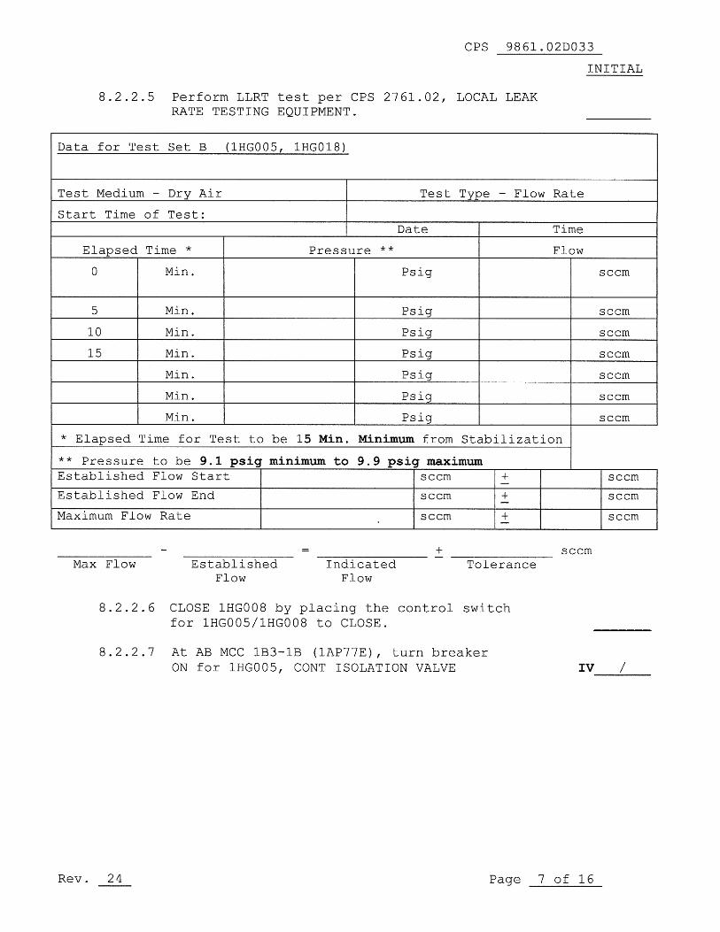
8.2.2.5 Perform LLRT test per CPS 2761.02, LOCAL LEAK RATE TESTING EQUIPMENT.
Data for Test Set B (lHG005, 1HG018)
Test Medium - Dry Air Test Type - Flow
Start Time of Test: Date
Elapsed Time * Pressure ** 0 Min. Psig
5 Min. Psig
10 Min. Psig
15 Min. Psig
Min. Psig
Min. Psig
Min. Psig
Rate
Time
Flow
* Elapsed Time for Test to be 15 Min. Minimum from Stabilization
** Pressure to be Established Flow
Established Flow
Maximum Flow Rate
Max Flow
9.1 psig minimum to 9.9 psig maximum Start
End
Established Flow
Indicated Flow
seem
seem
seem
+
+ -+ -+ -
Tolerance
8.2.2.6 CLOSE 1HG008 by placing the control switch for 1HG005/1HG008 to CLOSE.
seem
seem
seem
seem
seem
seem
seem
seem
seem
seem
seem
8.2.2.7 At AB MCC 1B3-1B (lAP77E), turn breaker ON for 1HG005, CONT ISOLATION VALVE IV ----.;..--
Rev. 24 Page 7 of 16

CPS 9861.02DO33
INITIAL8.2.3
TEST SET C (Closed Loop)
8.2.3.1 Position/Check Position the following valves:
a) (MCR 1H13-P800) OPEN/Check Open the followingvalves by placing their handswitch in TEST.
1) 1HGO08 Unit 1 CGCS CNMT Isol
(J)
2) 1HG005 Unit 1 CGCS CNMT Isol
(J)
b) Aux Bldg 762'
1) Lock OPEN/Check Locked Open 1HGO15Cont Return Hdr Isol (Recomb B)
2) Lock SHUT/Check Locked Shut 1HGO19Cont Return Hdr Test Conn(Recomb B) (RC,J)
c) Aux Bldg 781' W
1) Lock OPEN/Check Locked Open 1HGO14Cont Suct Hdr Isol (Recomb B)
2) Lock SHUT/Check Locked Shut 1HGO18Cont Suction Hdr Test Conn(Recomb B)(RC,J)
8.2.3.2 Lock OPEN/Check Locked Open the following valvesControl 702
a) 1HG006 H2 Recomb B Suct Isol
b) 1HGO07 H2 Recomb B Return Isol
8.2.3.3 Connect Leak Rate Test Equipment at the testconnections for 1MC-062 and/or 1MC-166, asdesired, by using a tee connection or similartest apparatus as necessary. If connecting toonly one test connection, the other test connectionwill need to be isolated with a cap/plug orflange.
CPS 9861.02D033
INITIAL 8.2.3 TEST SET C (Closed Loop)
8.2.3.1 Position/Check Position the following valves:
a) (MCR 1H13-P800) OPEN/Check Open the following valves by placing their handswitch in TEST.
1) 1HG008 Unit 1 CGCS CNMT Isol
2) IHG005 Unit 1 CGCS CNMT 1sol
b) Aux Bldg 762'
1) Lock OPEN/Check Locked Open IHG015 Cont Return Hdr 1sol (Recomb B)
2) Lock SHUT/Check Locked Shut IHG019 Cont Return Hdr Test Conn(Recomb B)
c) Aux Bldg 781' W
1) Lock OPEN/Check Locked Open 1HG014 Cont Suct Hdr Isol (Recomb B)
2) Lock SHUT/Check Locked Shut 1HG018
(J)
(J)
(RC, J)
Cont Suction Hdr Test Conn (Recomb B) (RC,J)
8.2.3.2 Lock OPEN/Check Locked Open the following valves Control 702
a) 1HG006 H2 Recomb B Suct 1sol
b) 1HG007 H2 Recomb B Return Isol
8.2.3.3 Connect Leak Rate Test Equipment at the test connections for 1MC-062 and/or IMC-166, as desired, by using a tee connection or similar test apparatus as necessary. If connecting to
Rev. 24
only one test connection, the other test connection will need to be isolated with a cap/plug or flange.
Page 8 of 16

CPS 9861.02D033
INITIAL
8.2.3.4 Perform LLRT test per CPS 2761.02 LOCAL LEAK RATETESTING EQUIPMENT.
Data for Test Set C Closed Loop
Test Medium - Dry Air
Start Time of Test:
Test Type - Flow Rate
Date
I
Time
Elapsed Time * Pressure **
I
Flow
0 Min. Psig sccm
5
Min.
10
Min.
15
Min.
Min.
Psig
Psig
Psig
Psig
Psig
Psig
sccm
sccm
sccm
sccm
sccm
sccm
Min.
Min.
* Elapsed Time for Test to be 15 Min. Minimum from Stabilization
** Pressure to be 9.1 psig minimum to 9.9 psig maximumEstablished Flow Start sccm
Established Flow End sccm +
Maximum Flow Rate sccm sccm
sccm
sccm
sccmMax Flow Established
FlowIndicated
FlowTolerance
8.2.4
Supplemental Test Lineups, if needed, to be addedIAW step 8.2.4 of CPS 9861.02.
Additional pages may be added if required.
8.2.4.1 Obtain the Shift/Assistant Shift Supervisorconcurrence IAW 8.2.4 of CPS 9861.02.
8.2.4.2 Obtain the LLRT Coordinator concurrence IAW 8.2.4of CPS 9861.02.
Rev. 24
Page 9 of 16
CPS 9861.02D033
INITIAL
8.2.3.4 Perform LLRT test per CPS 2761.02 LOCAL LEAK RATE TESTING EQUIPMENT.
Data for Test Set C Closed LooE
Test Medium - Dry Air Test Type - Flow Rate
Start Time of Test: Date Time
Elapsed Time * Pressure ** Flow
0 Min. Psig
5 Min. Psig
10 Min. Psig
15 Min. Psig
Min. Psig
Min. Psig
Min. Psig
* Elapsed Time for Test to be 15 Min. Minimum from Stabilization
** Pressure Established
Established
Maximum Flow
Max Flow
8.2.4
to be Flow
Flow
Rate
9.1 psig minimum to 9.9 psig maximum Start
End
Established Flow
Indicated Flow
seem
seem
seem
+
+ -
+ -+ -
Tolerance seem
Supplemental Test Lineups, if needed, to be added lAW step 8.2.4 of CPS 9861.02.
Additional pages may be added if required.
8.2.4.1 Obtain the Shift/Assistant Shift Supervisor concurrence lAW 8.2.4 of CPS 9861.02.
8.2.4.2 Obtain the LLRT Coordinator concurrence lAW 8.2.4 of CPS 9861.02.
Rev. 24 Page 9 of 16
seem
seem
seem
seem
seem
seem
seem
seem
seem
seem

CPS 9861.02D033
INITIAL
8.5
Restoration
8.5.1
SS/ASST.SS notified of test completion.
(DATE)
(TIME)
8.5.2
Restore control switch for 0HG01SB, CGCS RECOMB2, to STOP at 1H13-P800.
IV
/
8.5.3
Remove the test flanges and (or) plugs from 1HG03A.IV
8.5.4
Remove the test flanges and (or) plugs from 1HG04B.IV
8.5.5
Notify the CRS of test flange and plug removal.
8.5.6
Reinstall pipe cap on 1HGO19
8.5.7
Reinstall pipe cap on 1HGO18
8.5.8
The system is fully restored from testing usingthe following valve/electrical lineups:
OR
The system is partially restored due toplant/outage conditions and as directed by theSS/ASST SS. (List partial system status,i.e.: partial lineups performed, tagouts ineffect, MCR Log entries as appropriate)
8.5.9
Verify testing equipment removed.
8.5.10
LLRT tags removed if applicable
/
Restoration CompleteSS/ASST.SS
Date
Rev. 24
Page 10 of 16
IV /
IV
CPS 9861.02D033
INITIAL
8.5 Restoration
8.5.1
8.5.2
8.5.3
8.5.4
8.5.5
8.5.6
8.5.7
8.5.8
8.5.9
8.5.10
Rev. 24
SS/ASST.SS notified of test completion.
(DATE) (TIME)
Restore control switch for OHG01SB, CGCS RECOMB 2, to STOP at 1H13-P800. IV / ----Remove the test flanges and (or) plugs from 1HG03A.
IV / ----.:.---
Remove the test flanges and (or) plugs from 1HG04B.
Notify the CRS of test flange and plug removal.
Reinstall pipe cap on IHG019
Reinstall pipe cap on IHG018
The system is fully restored from testing using the following valve/electrical lineups:
OR
The system is partially restored due to plant/outage conditions and as directed by the SS/ASST SS. (List partial system status, i.e.: partial lineups performed, tagouts in effect, MCR Log entries as appropriate)
Verify testing equipment removed.
LLRT tags removed if applicable
IV ----.:.---
IV / -..........:....--
IV ----.:.---
------~------/------------- Restoration Complete SS/ASST.SS Date
Page 10 of 16

CPS 9861.02D033
INITIAL
9.0
ACCEPTANCE CRITERIA
9.1
Operability Requirements
9.1.1
This penetration does not have individual leakage limits.The leakage for any containment penetration should notcontribute excessively to the overall Type B and Type Cleak rate (ITS 3,6.1.1.1) and the Secondary ContainmentBypass Leakage Rate (SR 3.6.1.3.8). Leakage is monitoredby the Administrative Limit in 9.2.1 and by the NSED App JLLRT Engineer review.
9.2
Other Requirements
9.2.1
Administrative Limit: 500 sccm
9.2.1.1 If this limit is exceeded, immediately contact theISI Pressure Test Program Engineer/Designee toensure the commitments of Relief Request 13R-09are met.
9.2.1.2 If this limit is exceeded, initiate an IR andcontact the NSED App J LLRT Engineer forevaluation of overall Containment leakage(ITS 3.6.1.1.1) and Secondary Containment BypassLeakage (SR 3.6.1.3.8).
STEP Component Actual Leakage
8 2 1 5TEST SET A,
1HGO08, +.. .1HG019 sccm
8.2.2.5TEST SET B,
1HGO05, +
sccm1HGO18
8.2.3.4 TEST SET C, Closed Loop+
sccm-
An Administrative limit is a leakage limit which is defined in CPS1305.01 for the purpose of surveillance frequency extension ordesignated by the NSED Appendix J Coordinator to assist the Testperformer in determining acceptability of leakage.
NSED App J LLRT Engineer Actions:
1. Retrieve/obtain previous test results forComparison to the test results obtainedduring this test.
2. Compare test results to previous test results.Evaluate trends and initiate further actionif required.
Rev. 24
Page 11 of 16
CPS 9861.02D033
INITIAL
9.0 ACCEPTANCE CRITERIA
9.1 Operability Requirements
9.1.1 This penetration does not have individual leakage limits. The leakage for any containment penetration should not contribute excessively to the overall Type B and Type C leak rate (ITS 3.6.1.1.1) and the Secondary Containment Bypass Leakage Rate (SR 3.6.1.3.8). Leakage is monitored by the Administrative Limit in 9.2.1 and by the NSED App J LLRT Engineer review.
9.2 Other Requirements
9.2.1 Administrative Limit: 500 sccm
9.2.1.1 If this limit is exceeded, immediately contact the ISI Pressure Test Program Engineer/Designee to ensure the commitments of Relief Request I3R-09 are met.
9.2.1.2 If this limit is exceeded, initiate an IR and contact the NSED App J LLRT Engineer for evaluation of overall Containment leakage (ITS 3.6.1.1.1) and Secondary Containment Bypass Leakage (SR 3.6.1.3.8).
STEP Component Actual Leakage
8.2.1.5 TEST SET A, IHG008, + IHG019 -
8.2.2.5 TEST SET B, 1HG005, + -----1HG018
8.2.3.4 TEST SET C, Closed Loop + -----
sccm
sccm
sccm
An Administrative limit is a leakage limit which is defined in CPS 1305.01 for the purpose of surveillance frequency extension or designated by the NSED Appendix J Coordinator to assist the Test performer in determining acceptability of leakage.
Rev. 24
NSED App J LLRT Engineer Actions:
1. Retrieve/obtain previous test results for Comparison to the test results obtained during this test.
2. Compare test results to previous test results. Evaluate trends and initiate further action if required.
Page 11 of 16

CPS 9861.02DO33
INITIAL
9.0
ACCEPTANCE CRITERIA
9.2
Other Requirements (cont ` d)
ISI Pressure Test Program Engineer Actions:
1. Evaluate the test results to determine if theleakage is due to through-wall leakage inthe pressure boundary.
2. Ensure troubleshooting is performed to locatethe source of any excessive leakage (as needed).
3. Ensure any leakage identified is corrected andthe test set is run again. If troubleshootingdetermines that leakage above the administrativelimit may be attributed to a through-wall pressureboundary leak, VT-2 qualified personnel shallperform an examination of the affected areawith a leak detection solution. If through-wallpressure boundary leakage is discovered,immediately inform the Shift Management andensure the component or piping is repaired orreplaced in accordance with the applicableASME Code requirements.
4. If evidence of safety-related pressureboundary leakage is not located, the examinationwill be considered acceptable forISI Pressure Testing Program requirementsfor the ISI Period.
9.2.2
Once the total leakage per Test Set is less thanor equal to 500 sccm for Test Sets A,B,and C, theleakage may be considered acceptable and thissurveillance may be restored in a routine manner.
CPS 9861.02D033
INITIAL
9.0 ACCEPTANCE CRITERIA
9.2
9.2.2
Rev. 24
Other Requirements (cont'd)
lSI Pressure Test Program Engineer Actions:
1. Evaluate the test results to determine if the leakage is due to through-wall leakage in the pressure boundary.
2. Ensure troubleshooting is performed to locate the source of any excessive leakage (as needed) .
3. Ensure any leakage identified is corrected and
--------
the test set is run again. If troubleshooting determines that leakage above the administrative limit may be attributed to a through-wall pressure boundary leak, VT-2 qualified personnel shall perform an examination of the affected area with a leak detection solution. If through-wall pressure boundary leakage is discovered, immediately inform the Shift Management and ensure the component or piping is repaired or replaced in accordance with the applicable ASME Code requirements.
4. If evidence of safety-related pressure boundary leakage is not located, the examination will be considered acceptable for lSI Pressure Testing Program requirements for the lSI Period.
Once the total leakage per Test Set is less than or equal to 500 sccm for Test Sets A,B,and C, the leakage may be considered acceptable and this surveillance may be restored in a routine manner.
Page 12 of 16

CPS 9861.02D033
SUPPLEMENTAL REVIEW SHEET
CORRECTIVE ACTION TAKEN
9.1 OPERABILITY Requirements
ITS LCOs:
3.6.1.3
ORM Ors:
2.4.10
2.5.2
ODCM Ors:
None
As applicable:Initiated Issue Report
(yes/no)
Initiated Issue Report (IR) No.
9.2 OTHER Requirements
As applicable:Initiated Issue Report
(fires/no)
Initiated Issue Request (IR) No.
NOTES/COMMENTS
REVIEW AND APPROVAL
NSED LLRT Coordinator:
Pressure Test Program Manager:
IST Program Coordinator:
Shift Management:
Rev. 24
(Signature)
(Signature)
(Signature)
(Signature)
(Date)
(Date)
(Date)
(Date)
Page 13 of 16
SUPPLEMENTAL REVIEW SHEET
CORRECTIVE ACTION TAKEN
9.1 OPERABILITY Requirements
ITS LCOs:
ORM Ors:
3.6.1.3
2.4.10
ODCM Ors: None
As applicable: Initiated
Initiated
9.2 OTHER Requirements
As applicable:
Issue
Issue
Initiated Issue Report
2.5.2
Report (yes/no)
Report (IR) No.
(yes/no)
Initiated Issue Request (IR) No.
NOTES/COMMENTS
REVIEW AND APPROVAL
NSED LLRT Coordinator: (Signature)
Pressure Test Program Manager: (Signature)
1ST Program Coordinator: (Signature)
Shift Management: (Signature)
Rev. 24
CPS 9861.02D033
(Date)
(Date)
(Date)
(Date)
Page 13 of 16

CPS 9861.02D033
1MC-062 TEST SET A LINEUP
OHGOISB
HYDROGEN
RECOMBINER
Filled in valves = shut Test Boundary in Bold
Procedure Step EIN Position
8.2.1.lal 1HG008 Shut
(J)8.2.1.1a3 1HG005 Open
(J)8.2.1.lbl 1HGO15 Open8.2.1.1b2 1HGO19 Shut
(RC,J)8.2.1.1cl 1HGO14 Open
(TV)8.2.1.1c2 1HG018 Shut
(RC,J)8.2.1.2a 1HG006 Open8.2.1.2b 1HG007 Open8.2.1.2c OHGOISB-V3 Open
Rev_ 24
CPS 9861.02D033
IMC-062 TEST SET A LINEUP
_L-
OONT~~ _B ...... ILD
_
G
. ---.,II~~ '""'" i ~ .... ---+1 'MC-62 r bL.jr--I-----,.
1HG015 1HGOO8
--1HGOO7 0
TC
Penetration No. 062/
Elev. 763'6- Az 294 deg
Elev. 789' Az 291 deg
P&ID M05-1063-1
M05-2063-1
2HG007 2HG006
TeA? TCAP
• • 0ri 1HG006
OHG01SB
HYDROGEN
RECOMBINER
Filled in valves shut Test Boundary in Bold
Procedure Step EIN Position 8.2.1.1a1 1HG008 Shut ( J)
8.2.1.1a3 1HG005 Open (J)
8.2.1.1b1 1HG015 Open 8.2.1.1b2 1HG019 Shut (RC, J)
8.2.1.1c1 1HG014 Open (TV) 8.2.1.1c2 1HG018 Shut (RC f J)
8.2.1.2a 1HG006 Open 8.2.1.2b 1HG007 Open 8.2.1.2c OHG01SB-V3 Open
Page 14 of 16
CPS 9861.02DO33
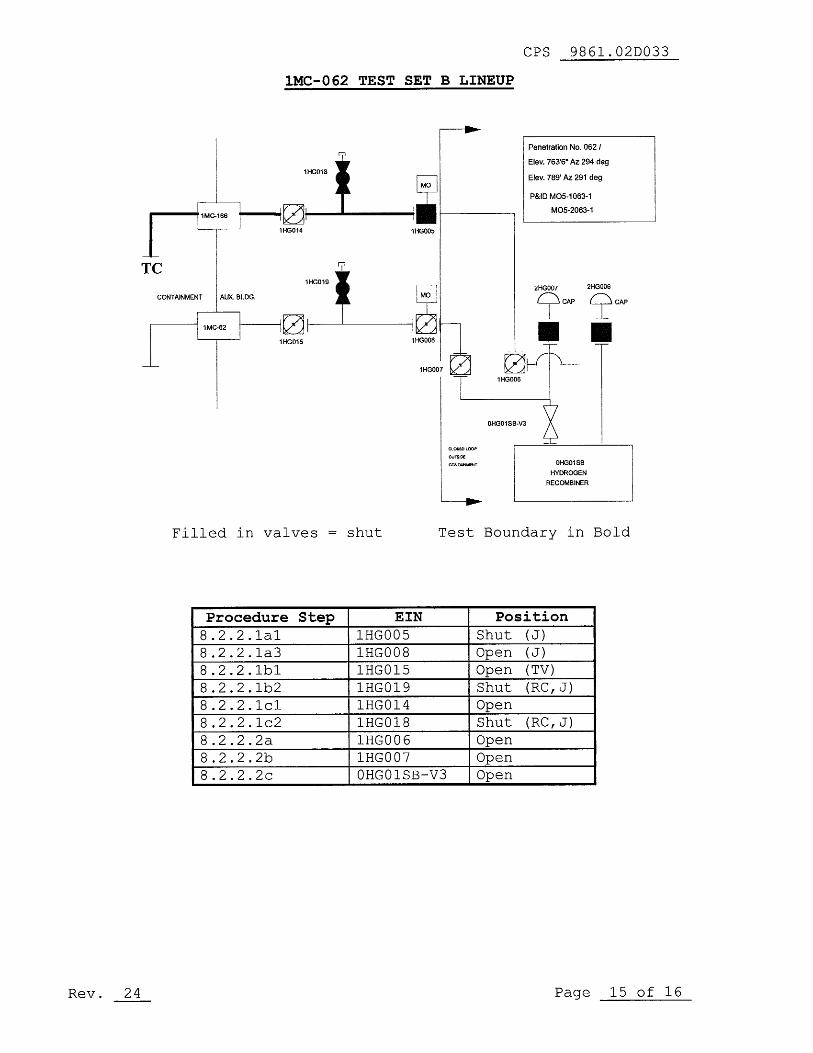
1MC-062 TEST SET B LINEUP
Penetration No. 062 /
Elev. 763'6' Az 294 deg
Elev. 789' Az 291 deg
1HGO06
1HGO15
1110005
I1HGD18
1110008
7
1HGOD7
OHGO1S6-V3
WILNE`OW
cwrr«r.^r
OHGO1S6
HYDROGEN
RECOMBINER
Filled in valves = shut
Test Boundary in Bold
Procedure Step EIN Position
8.2.2.1al 1HGO05 Shut
(J)
8.2.2.1a3 1HGO08 Open
(J)
8.2.2.lbl 1HGO15 Open
(TV)
8.2.2.1b2 1HGO19 Shut
(RC,J)
8.2.2.1cl 1HGO14 Open
8.2.2.1c2 1HGO18 Shut
(RC,J)
8.2.2.2a 1HGO06 Open
8.2.2.2b 1H0007 Open
8.2.2.2c OHG01SB-V3 Open
Rev. 24
Page 15 of 16Rev. 24
CPS 9861.02D033
lMC-062 TEST SET B LINEUP
Penetration No. 062 I
Elev. 763'6" Az 294 deg
Elev. 789' Az 291 deg
P&ID M05--1 063-1
M05-2063-1
I~ LII~'HG'" i ~ ..... ---+1'·.,'" I b<::.J-~-"f-----------'
1HG014 100005
--
f-.--II0
1:L019 7 ~ CONTAINMENT AUX. BLDG.
-,,.......--1------'1 r------;I 1MC-62 I
TC
1HG015 100008
-~
Filled in valves shut
Procedure Step EIN 8.2.2.1al IHGOO5 8.2.2.1a3 IHGOO8 8.2.2.1bl IHG015 8.2.2.1b2 IHG019 8.2.2.1cl IHG014 8.2.2.1c2 IHG018 8.2.2.2a IHGOO6 8.2.2.2b IHGOO7
22?~ 2~~
• • 0~
1HG006
OHG01SB-V3
OHG01SB
HYDROGEN RECOMBINER
Test Boundary in Bold
Position Shut ( J)
Open ( J)
Open (TV) Shut (RC , J)
Open Shut (RC , J)
Open Open
8.2.2.2c OHGOISB-V3 Open
Page 15 of 16
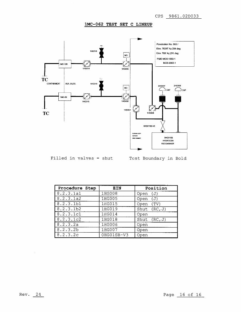
CPS 9861.02DO33
1MC-062 TEST SET C LINEUP
n
1HGO18
MG
Penetration No. 062 /
Elev. 763'6' Az 294 deg
Elev. 789' Az 291 deg
P&tO MO5-1063-1
M05-2063-1C- 01HGO14
1HG005
TCCONTAINMENT AUX. BLDG.
1HGO192HH0007
2HGD06
L07 CAP £ CPI
IH0006
LI)1MC-62
1HGD15
TC
Filled in valves = shut
Test Boundary in Bold
Procedure Step EIN Position8.2.3.1a1 1H0008 Open
(J)8.2.3.1a2 1HGO05 Open
(J)8.2.3.lbl 1HGO15 Open
(TV)8.2.3.1b2 1HGO19 Shut
(RC,J)8.2.3.1c1 1HGO14 Open
8.2.3.1c2 1HGO18 Shut
(RC,J)8.2.3.2a 1HGO06 Open8.2.3.2b 1H0007 Open8.2.3.2c OHGOISB-V3 Open
Rev. 24
Page 16 of 16Rev. 24
CPS 9861.02D033
lMC-062 TEST SET C LINEUP
Penetration No. 062 I
I+-1
_--+:0:Lo18 7 ~ Elev.763'6"Az294deg Elev. 789' Az 291 deg
P&ID M05-1 063-1
..... -.....,1 1MC-166 I 1-----..... ,-_M_O_5-_20_63_-1_~_----, 1HG014 1HGOO5
--
TSONTAI<"'~ "".BJ...-ILD
_
G
. --+I~ ':L'" c,' ~ ..... ---+1 1MC-62 r k:Ll 0
1HG015 100008
TC
Filled in valves shut
Procedure Step EIN 8.2.3.1a1 1HGOO8 8.2.3.1a2 1HGOO5 8.2.3.1b1 1HG015 8.2.3.1b2 1HG019 8.2.3.1c1 1HG014 8.2.3.1c2 1HG018 8.2.3.2a 1HGOO6 8.2.3.2b 1HGOO7 8.2.3.2c OHG01SB-V3
2HG007 2HG006
~CAP ~CAP
• • OHG01SB
HYDROGEN
RECOMBINER
Test Boundary in Bold
Position Open ( J)
Open ( J)
Open (TV)
Shut (RC, J)
Open Shut (RC, J)
Open Open Open
Page 16 of 16

CPS 9861.02DO41
LLRT DATA SHEET FOR 1MC071 & 1MC072 H2 RECOMBINER
SCOPE OF REVISION:
• Incorporated specific change 23a; rev marks not retained.
• IR 1392302
Add new evaluation and troubleshooting requirements for thePressure Test Program Engineer immediately upon determination thata test set exceeds the administrative limit to comply withRelief Request 13R-09.
CONTINUOUS USE
ORIGINATOR : HD Jeans
SQR: Lee Anderson
CLASS CODE : SNNII
APPROVAL DATE : 02/06/2013
CURRENT CHANGES TO GENERAL REVISIONChange #
Date
List of Affected Pages
0
000
Rev. 24
Page 1 of 17
CPS 9861.02D041
LLRT DATA SHEET FOR lMC071 & lMC072 H2 RECOMBlNER
SCOPE OF REVISION:
• Incorporated specific change 23a; rev marks not retained.
• IR 1392302 Add new evaluation and troubleshooting requirements for the Pressure Test Program Engineer immediately upon determination that a test set exceeds the administrative limit to comply with Relief Request 13R-09.
I COIITIIIUOUS USE
I
ORIGINATOR: HD Jeans CLASS CODE: SNNI1
SQR: Lee Anderson APPROVAL DATE: 02106/2013
CURRENT CHANGES TO GENERAL REVISION Change # Date List of Affected Pages
o 8 ------
@ e ------o ------
Rev. 24 Page 1 of 17

CPS 9861.02D041
1.0
The purpose of this test is to perform a9.1 (-0, +.8) psig air test on Penetrations1MC071/72. The components/valves to betested are: 1HG001, 1HG004, 1HG016, 1HGO17,Closed Loop.
5.0
PREREQUISITES
5.1
In conjunction with the Shift Manager/ControlRoom Supervisor (SM/CRS), review the followingimpact statements to determine required plantstatus to perform this test:
TECH SPEC FUNCTIONS IMPACTED
ITS 3.6.1.1 PRIMARY CONTAINMENTITS 3.6.1.3 PRIMARY CONTAINMENT ISOLATION VALVESITS 3.6.4.1 SECONDARY CONTAINMENTORM 2.4.10 PRIMARY CONTAINMENT HYDROGEN RECOMBINERSITS SR 3.6.1.3.8 SECONDARY CONTAINMENT BYPASS LEAKAGE
RPS TRIP - N/A
CRVICS ISOLATION - N/A
LOGIC TYPE - N/A
MINIMUM OPERABLE CHANNELS -N/A
PLANT/SYSTEM CONDITIONS REQUIRED TO CONDUCT THIS TEST
Modes 4 or 5
Hydrogen Recombiner 0HG01SA secured.
No movement of recently irradiated fuel assembliesin the primary or secondary containment.
No operation with a potential for drainingthe reactor vessel (OPDRVs).
OTHER SYSTEMS AFFECTED - N/A
OTHER CHANNELS REQUIRED OPERABLE TO PREVENT INADVERTENTACTUATION - NA
SM/CRS
Performer
5.2
Obtain the SM/CRS permissionto perform the surveillance.
DATE / TIME
SM/CRS
5.3
OHGOISA is secured and disabled.
CPS 9861.02D041
1.0 The purpose of this test is to perform a 9.1 (-0, +.8) psig air test on Penetrations 1MC071/72. The components/valves to be tested are: 1HG001, 1HG004, 1HG016, 1HG017, Closed Loop.
5.0 PREREQUISITES
5.1 In conjunction with the Shift Manager/Control Room Supervisor (SM/CRS), review the following impact statements to determine required plant status to perform this test:
TECH SPEC FUNCTIONS IMPACTED
ITS 3.6.1.1 PRIMARY CONTAINMENT ITS 3.6.1.3 PRIMARY CONTAINMENT ISOLATION VALVES ITS 3.6.4.1 SECONDARY CONTAINMENT ORM 2.4.10 PRIMARY CONTAINMENT HYDROGEN RECOMBINERS ITS SR 3.6.1.3.8 SECONDARY CONTAINMENT BYPASS LEAKAGE
RPS TRIP - N/A
CRVICS ISOLATION - N/A
LOGIC TYPE - N/A
MINIMUM OPERABLE CHANNELS -N/A
PLANT SYSTEM CONDITIONS TO CONDUCT THIS TEST
Modes 4 or 5
Hydrogen Recombiner OHG01SA secured.
No movement of recently irradiated fuel assemblies in the primary or secondary containment.
No operation with a potential for draining the reactor vessel (OPDRVs).
OTHER SYSTEMS AFFECTED - N/A
OTHER CHANNELS REQUIRED OPERABLE TO PREVENT INADVERTENT ACTUATION - NA
SM/CRS Performer
5.2 Obtain the SM/CRS permission to perform the surveillance.
DATE TIME SM/CRS
5.3 OHG01SA is secured and disabled.
Rev. 24 Page 2 of 17

CPS 9861,02D041
INITIAL5.4
Install the test plug/flange:
5.4.1
Notify the RO/CRS of test plug/flangesinstallation.
5.4.2
Install a test plug/flange on/in lines 1HG01Aand 1HG02B. (either 2" Thaxton plugs or 2" 150#flanges with 3/8" tubing connections andtemporary gaskets). CV
7.0
MATERIALS AND/OR TEST EQUIPMENT
TEST EQUIPT EIN RANGE TOLERANCE CAL DUE
Flowmeter
Flowmeter
Flowmeter
Press Gauge
Press Gauge
PROCEDURE
Throughout the procedure the followingabbreviations shall be used:(RC) = remove cap
(TV) = test vent(TC) = test connection
(DR) = drain valve(TR) = tested in the reverse direction(J) = tested valve which shall always be shut by its
normal means(B) = boundary valve(SC) = Secondary Containment violation(LC) = Locked Closed
Steps within section 8.2 may be performed in any order andreperformed as necessary a test performer discretion, withthe following cautions:
•
If performing the test sets of section 8.2 out of thenormal sequence (i.e., first test A, then test B,etc.), ensure that all valves within the test boundaryare positioned appropriately to support the given testset. Not all valve positionings are repeated for eachtest set. It may be necessary to append the test setlineup (i.e., to open a vent that would normally beopened in a previous test set) using section 8.2.4.
•
Test boundary valves should be shut (denoted with a B)to prevent inleakage and to bound the test volume priorto positioning other valves within the test boundary.If needed, additional boundary isolation may beprovided IAW section 8.2.4.
Rev. 24
Page 3 of 17
5.4
5.4.1
5.4.2
CPS 9861.02D041
INITIAL Install the test plug/flange:
Notify the RO/CRS of test plug/flanges installation.
Install a test plug/flange on/in lines 1HG01A and 1HG02B. (either 2" Thaxton plugs or 2" 150# flanges with 3/8" tubing connections and temporary gaskets) . cv / --------
7.0 MATERIALS AND/OR TEST EQUIPMENT
TEST EQUIPT EIN RANGE TOLERANCE CAL DUE
Flowmeter
Flowmeter
Flowmeter
Press Gauge
Press Gauge
8.0 PROCEDURE
Rev. 24
Throughout the procedure the following abbreviations shall be used: (RC) remove cap (TV) = test vent (TC) test connection (DR) = drain valve (TR) tested in the reverse direction (J) tested valve which shall always be shut by its
normal means (B) boundary valve (SC) Secondary Containment violation (LC) Locked Closed
Steps within section 8.2 may be performed in any order and reperformed as necessary a test performer discretion, with the following cautions: • If performing the test sets of section 8.2 out of the
normal sequence (i.e., first test A, then test B, etc.), ensure that all valves within the test boundary are positioned appropriately to support the given test set. Not all valve positionings are repeated for each test set. It may be necessary to append the test set lineup (i.e., to open a vent that would normally be opened in a previous test set) using section 8.2.4.
• Test boundary valves should be shut (denoted with a B) to prevent inleakage and to bound the test volume prior to positioning other valves within the test boundary. If needed, additional boundary isolation may be provided lAW section 8.2.4.
Page 3 of 17
CPS 9861.02D041
INITIAL
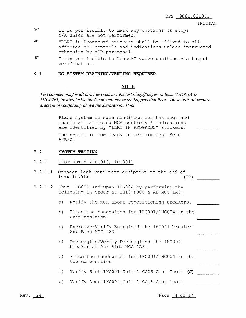
It is permissible to mark any sections or stepsN/A which are not performed.
"LLRT in Progress" stickers shall be affixed to allaffected MCR controls and indications unless instructedotherwise by MCR personnel.
It is permissible to "check" valve position via tagoutverification.
8.1
NO SYSTEM DRAINING/VENTING REQUIRED
NOTE
Test connections for all three test sets are the test plugs/flanges on lines (IHGOIA &
IHG02B), located inside the Cnmt wall above the Suppression Pool. These tests all requireerection of scaffolding above the Suppression Pool.
Place System in safe condition for testing, andensure all affected MCR controls & indicationsare identified by "LLRT IN PROGRESS" stickers.
The system is now ready to perform Test SetsA/B/C.
8.2
SYSTEM TESTING
8.2.1
TEST SET A (1HGO16, 1HGO01)
8.2.1.1 Connect leak rate test equipment at the end ofline 1HG01A.
(TC)
8.2.1.2 Shut 1HGO01 and Open 1HGO04 by performing thefollowing in order at 1H13-P800 & AB MCC 1A3:
a) Notify the MCR about repositioning breakers.
b) Place the handswitch for 1HG001/1HG004 in theOpen position.
c) Energize/Verify Energized the 1HG001 breakerAux Bldg MCC 1A3.
d) Deenergize/Verify Deenergized the 1HGO04breaker at Aux Bldg MCC 1A3.
Place the handswitch for 1HG001/1HG004 in theClosed position.
f) Verify Shut 1HGO01 Unit 1 CGCS Cmnt Isol. (J)
g) Verify Open 1HGO04 Unit 1 CGCS Cmnt Isol.
Rev. 24
Page 4 of 17
CPS 9861.02D041
INITIAL
It is permissible to mark any sections or steps N/A which are not performed.
~LLRT in Progress" stickers shall be affixed to all affected MCR controls and indications unless instructed otherwise by MCR personnel.
It is permissible to ~check" valve position via tagout verification.
8.1 NO SYSTEM DRAINING/VENTING REQUIRED
NOTE
Test connections/or all three test sets are the test plugsljlanges on lines (lHG01A & lHG02B), located inside the Cnmt wall above the Suppression Pool. These tests all require erection of scaffolding above the Suppression Pool.
Place System in safe condition for testing, and ensure all affected MCR controls & indications are identified by ~LLRT IN PROGRESS" stickers.
The system is now ready to perform Test Sets A/B/C.
8.2 SYSTEM TESTING
8.2.1 TEST SET A (lHG016, IHG001)
8.2.1.1 Connect leak rate test equipment at the end of line IHGOIA. (TC)
8.2.1.2 Shut IHGOOl and Open 1HG004 by performing the following in order at 1H13-P800 & AB MCC 1A3:
Rev. 24
a) Notify the MCR about repositioning breakers.
b) Place the handswitch for IHG001/1HG004 in the Open position.
c) Energize/Verify Energized the 1HG001 breaker Aux Bldg MCC lA3.
d) Deenergize/Verify Deenergized the 1HG004 breaker at Aux Bldg MCC lA3.
e) Place the handswitch for 1HG001/1HG004 in the Closed position.
f) Verify Shut 1HG001 Unit 1 CGCS Cmnt Isol. (J)
g) Verify Open 1HG004 Unit 1 CGCS Cmnt Isol.
Page 4 of 17

CPS 9861.02D041
INITIAL
8.2.1.3 Shut/Check Shut 1HGO16, Cnmt Suction Hdr Test Conn(Aux Bldg 755' RT Pmp Room Mezz).
(RC,J)
8.2.1.4 Open/Check Open the following: (Cont Bldg 702')
a) 1HG002, H2 Recombiner Suct Isol
b) 1HG003, H2 Recombiner Return Isol
8.2.1.5 Open/Check Open the following:(Aux Bldg 755', RT Pmp Rm Mezz)
a) 1HGO12, Cnmt Suction Hdr Isol
b) 1HGO13, Cnmt Return Isol
8.2.1.6 Remove/Verify removed the blank flange on line1HG02B; ensure line is vented. (Cnmt 750')
(TV)
8.2.1.7 Perform LLRT per CPS 2761.02, LOCAL LEAKRATE TESTING EQUIPMENT.
Test Set A (1HG001, 1HGO16)
Test Medium - Dry Air Test Type - Flow Rate
Start Time of Test:
Date T e
Elapsed Time*
0 min
5 min
10
15
Pressure**
psig
psig
psig
psig
Flow
sccm
sccm
sccm
sccm
sccm
sccm
* Elapsed time for test to be min. minimum from stabilization.
** Pressure to be 9.1 psig minimum to 9.9 psig maximum.
Established Flow Start
Established Flow End
Maximum Flow Rate
sccm
sccm
Sscm
sccm
sccm
sccm
+
scorn
Max Flow EstablishedFlow
IndicatedLeakage
Tolerance
Rev. 24
Page 5 of 17
CPS 9861.020041
INITIAL
8.2.1.3 Shut/Check Shut IHG016, cnmt Suction Hdr Test Conn (Aux Bldg 755' RT Pmp Room Mezz) . (RC,J)
8.2.1.4 Open/Check Open the following: (Cant Bldg 702')
a) IHG002, H2 Reeombiner Suet 1sol
b) IHG003, H2 Reeombiner Return 1sol
8.2.1.5 Open/Check Open the following: (Aux Bldg 755', RT Pmp Rm Mezz)
a) IHG012, Cnmt Suction Hdr 1sol
b) IHG013, Cnmt Return Isol
8.2.1.6 Remove/Verify removed the blank flange on line IHG02B; ensure line is vented. (Cnmt 750') (TV)
8.2.1.7 Perform LLRT per CPS 2761.02, LOCAL LEAK RATE TESTING EQUIPMENT.
Test Set A (lHGOOl, IHG016)
Test Medium - Dry Air Test Type - Flow
Start Time of Test:
Rate
Date Time
Elapsed Time* Pressure** Flow
0 min
5 min
10 min
15 min
min
min
* Elapsed time for test to
** Pressure to be 9.1 psig
Established Flow Start
Established Flow End Maximum Flow Rate
Max Flow
Rev. 24
Established Flow
psig
psig
psig
psig
psig
psig
be 15 min. minimum
minimum to 9.9 psig
seem
seem
Ssem
Indicated Leakage
seem
seem
seem
seem
seem
seem
from stabilization.
maximum. + seem -+ seem -+ seem -
+ seem
Tolerance
Page 5 of 17

CPS 9861.02D041
INITIAL8.2.2
TEST SET B (1HG017, 1HG004)
8.2.2.1 Connect leak rate test equipment at the end ofline 1HG02B.
(TC)
8.2.2.2 Shut 1HG004 and Open 1HG001 by performing thefollowing in order at 1H13-P800 & AB MCC 1A3:
a) Notify the MCR about repositioning breakers.
b) Place the handswitch for 1HG001/1HGO04 in theOpen position.
c) Energize/Verify Energized the 1HG004 breakerat Aux Bldg MCC 1A3.
d) Deenergize/Verify Deenergized the 1HG001breaker at Aux Bldg MCC 1A3.
e) Place the handswitch for 1HGOQ1/1HG004 in theClosed position.
f) Verify Shut 1HGO04 Unit 1 CGCS Cmnt Isol. (J)
g) Verify Open 1HGO01 Unit 1 CGCS Cmnt Isol.
8.2.2.3 Shut/Check Shut 1HGO17, Cnmt Return Hdr Test Conn(Aux Bldg 755' RT Pmp Room Mezz).
(RC,J)
8.2.2.4 Open/Check Open the following: (font Bldg 702')
a) 1HG002, H2 Recombiner Suct Isol
b) 1HG003, H2 Recombiner Return Isol
8.2.2.5 Open/Check Open the following:(Aux Bldg 755', RT Pmp Rm. Mezz)
a) 1HG012, Cnmt Suction Hdr Isol
b) 1HGO13, Cnmt Return Isol
8.2.2.6 Remove/Verify Removed the blank flange on line1HGO1A; ensure line is vented (Cnmt 750').
CPS 9861.02D041
INITIAL 8.2.2 TEST SET B (lHG017, 1HG004)
8.2.2.1 Connect leak rate test equipment at the end of line 1HG02B. (TC)
8.2.2.2 Shut 1HG004 and Open 1HG001 by performing the following in order at 1H13-P800 & AB MCC 1A3:
a) Notify the MCR about repositioning breakers.
b) Place the handswitch for 1HG001/1HG004 in the Open position.
c) Energize/Verify Energized the 1HG004 breaker at Aux Bldg MCC 1A3.
d) Deenergize/Verify Deenergized the 1HG001 breaker at Aux Bldg MCC 1A3.
e) Place the handswitch for 1HG001/1HG004 in the Closed position.
f) Verify Shut 1HG004 Unit 1 CGCS Cmnt Isol. (J)
g) Verify Open 1HG001 Unit 1 CGCS Cmnt Isol.
8.2.2.3 Shut/Check Shut 1HG017, Cnmt Return Hdr Test Conn (Aux Bldg 755' RT Pmp Room Mezz) . (RC,J)
8.2.2.4 Open/Check Open the following: (Cont Bldg 702')
a) 1HG002, H2 Recombiner Suct Isol
b) 1HG003, H2 Recombiner Return 1s01
8.2.2.5 Open/Check Open the following: (Aux Bldg 755', RT Pmp Rm Mezz)
a) 1HG012, Cnmt Suction Hdr Isol
b) 1HG013, Cnmt Return 1801
8.2.2.6 Remove/Verify Removed the blank flange on line 1HG01A; ensure line is vented (Cnmt 750').
Rev. 24 Page 6 of 17

CPS 9861.02D041
INITIAL
8.2.2.7 Perform LLRT per CPS 2761.02, Local LeakRate Testing Equipment.
Test Set B (1HGO04 And 1HGO17)
Test Medium - Dry Air Test Type - Flow Rate
Start Time of Test:
Elapsed Time*
Date
Pressure**
Time
Flow
0
5
10
15
min
min
min
min
min
min
psig
psig
psig
psig
psig
psig
sccm
sccm
sccm
sccm
sccm
sccm
* Elapsed time for test to be 15 min. minimum from stabilization.
** Pressure to be 9.1 psig minimum to 9.9 psig maximum.
Established Flow Start
Established Flow End
Maximum Flow Rate
sccm
sccm
Sscm
sccm
sccm
seem
+ sccm
ToleranceMax Flow
Established
IndicatedFlow
Leakage
CPS 9861.02D041
INITIAL
8.2.2.7 Perform LLRT per CPS 2761.02, Local Leak Rate Testing Equipment.
Test Set B (lHGO 0 4 And 1HG017) Test Medium - Dry Air Test Type - Flow Rate
Start Time of Test: Date Time
Elapsed Time* Pressure** Flow
0 min
5 min
10 min
15 min
min
min
* Elapsed time for test to
** Pressure to be 9.1 psig
Established Flow Start
Established Flow End
Maximum Flow Rate
Max Flow
Rev. 24
Established Flow
psig
psig
psig
psig
psig
psig
be 15 min. minimum
minimum to 9.9 psig seem
seem
Ssem
Indicated Leakage
seem
seem
seem
seem
seem
seem
from stabilization.
maximum. + seem -
+ seem -+ seem -
+ seem
Tolerance
Page 7 of 17

CPS 9861.02D041
INITIAL
NOTE
Test set 'C' results are to be included in the Type C totals only if it is performed after the mostrecent ILRT and need not be performed unless leak rate boundaries outside of the containmentisolations valves have been disturbed.
8.2.3
TEST SET C (Closed Loop)
8.2.3.1 Connect leak rate test equipment at the end oflines 1HG02B and 1HG01A.
1HG02B
(TC)
1HG01A
(TC)
8.2.3.2 Open/Check Open 1HGO01 & 1HGO04 by performing thefollowing in order at 1H13-P800 & AB MCC-1A3:
a) Notify the MCR about repositioning breakers.
b) Energize/Verify Energized the 1HGO04 breakerat Aux Bldg MCC 1A3.
c) Energize /Verify Energized the 1HGO01 breakerat Aux Bldg MCC 1A3.
d) Place the handswitch for lHG001/1HG004 in theOpen position.
e) Verify Open 1HGO04 Unit 1 CGCS Cmnt Isol.
f) Verify Open 1HGO01 Unit 1 CGCS Cmnt Isol.
8.2.3.3 Shut/Check Shut the following: (Aux Bldg 755' RTPmp Room Mezz)
a) 1HG016, Cnmt Suction Hdr Test Conn
b) 1HGO17, Cnmt Return Hdr Test Conn
8.2.3.4 Shut/Check Shut the following: (Cont Bldg 702')
a) 2HG002, H2 Recombiner Suct Isol
(LC)
b) 2HG003, H2 Recombiner Return Isol
(LC)
8.2.3.5 Open/Check Open the following: (Cont Bldg 702')
a) 1HG002, H2 Recombiner Suet Isol
b) 1HG003, H2 Recombiner Return Isol
Rev. 24
Page 8 of 17
NOTE
CPS 9861.02D041
INITIAL
Test set 'C' results are to be included in the Type C totals only if it is performed after the most recent ILRT and need not be performed unless leak rate boundaries outside of the containment isolations valves have been disturbed.
8.2.3 TEST SET C (Closed Loop)
8.2.3.1 Connect leak rate test equipment at the end of lines 1HG02B and 1HG01A. 1HG02B (TC)
1HG01A (TC)
8.2.3.2 Open/Check Open 1HG001 & 1HG004 by performing the following in order at 1H13-P800 & AB MCC-1A3:
a) Notify the MCR about repositioning breakers.
b) Energize/Verify Energized the 1HG004 breaker at Aux Bldg MCC 1A3.
c) Energize/Verify Energized the 1HG001 breaker at Aux Bldg MCC 1A3.
d) Place the handswitch for 1HG001/1HG004 in the Open position.
e) Verify Open 1HG004 Unit 1 CGCS Cmnt Isol.
f) Verify Open 1HG001 Unit 1 CGCS Cmnt Isol.
8.2.3.3 Shut/Check Shut the following: (Aux Bldg 755' RT Prnp Room Me z z)
a) 1HG016, Cnrnt Suction Hdr Test Conn
b) 1HG017, Cnmt Return Hdr Test Conn
8.2.3.4 Shut/Check Shut the following: (Cont Bldg 702')
a) 2HG002, H2 Recombiner Suct Isol
b) 2HG003, H2 Recornbiner Return Isol
(LC)
(LC)
8.2.3.5 Open/Check Open the following: (Cant Bldg 702')
a) 1HG002, H2 Recornbiner Suct Isol
b) 1HG003, H2 Recornbiner Return Isol
Rev. 24 Page 8 of 17

CPS 9861.02D041
INITIAL8.2.3.6 Shut/Check Shut the following: (Aux Bldg 707',
(LPCS Pmp Room)
a) 1HG020, Cnmt Suction Hdr Drain
b) 1HG021, Cnmt Return Drain
8.2.3.7 Open/Check Open the following:(Aux Bldg 755', (RT Pmp Rm Mezz)
a) 1HGO12, Cnmt Suction Hdr Isol
b) 1HGO13, Cnmt Return Isol
8.2.3.8 Perform LLRT per CPS 2761.02, Local LeakRate Testing Equipment.
Test Set C (Closed Loop)Test Medium - Dry Air Test Type - Flow Rate
Start Time of Test:Date Time
Elapsed Time* Pressure** Flow
0 min psig sccm
5 min psig sccm
10 min psig sccm
15 min psig sccm
min psig sccm
min psig sccm
* Elapsed time for test to be 15 min. minimum from stabilization.
** Pressure to be 9.1 psig minimum to 9.9 psig maximum.
Established Flow Start sccm + sccm
Established Flow End sccm + sccm
I Maximum Flow Rate Sscm ± sccm
sccm
Max Flow EstablishedFlow
IndicatedLeakage
Tolerance
Rev. 24
Page 9 of 17
CPS 9861.02D041
INITIAL 8.2.3.6 Shut/Check Shut the following: (Aux Bldg 707',
(LPCS Pmp Room)
a) IHG020, Cnmt Suction Hdr Drain
b) 1HG021, Cnmt Return Drain
8.2.3.7 Open/Check Open the following: (Aux Bldg 755' , (RT Pmp Rm Mezz)
a) 1HG012, Cnmt Suction Hdr Isol
b) IHG013, Cnmt Return Isol
8.2.3.8 Perform LLRT per CPS 2761.02, Local Leak Rate Testing Equipment.
Test Set C (Closed Loop) Test Medium - Dry Air Test Type -
Start Time of Test: Date
Elapsed Time* Pressure**
0 min
5 min
10 min
15 min
min
min
* Elapsed time for test to
** Pressure to be 9.1 psig
Established Flow Start
Established Flow End
Maximum Flow Rate
Max Flow Established Flow
psig
psig
psig
psig
psig
psig
be 15 min. minimum
minimum to 9.9 psig
seem
seem
Ssem
Indicated Leakage
Flow Rate
Time
Flow
seem
seem
seem
seem
seem
seem
from stabilization.
maximum. + seem -+ seem -+ seem -
+ seem
Tolerance
Rev. 24 Page 9 of 17

CPS 9861.02D041
INITIAL
8.2.4
Supplemental Test Lineups, if needed, to be addedTAW step 8.2.4 of CPS 9861.02. Additional pagesmay be added if required.
8.2.4.1 Obtain the SM/CRS concurrenceIAW 8.2.4 of CPS 9861.02.
8.2.4.2 Obtain the LLRT Coordinator concurrence IAW 8.2.4of CPS 9861.02.
8.3
RESTORATION
8.3.1
SM/CRS notified of test completion.
Date / Time
8.3.2
OHG01SA is restored.
8.3.3
Test plug/flange removal:
8.3.3.1 Remove the test plug/flange from lines 1HGO1Aand 1HG02B. CV
/
8.3.3.2 Notify the RO/CRS of test plug/flange removal.
8.3.4
Breakers for 1HG001 and 1HG004 have beenrestored.
Date / Time
CPS 9861.02D041
INITIAL
8.2.4 Supplemental Test Lineups, if needed, to be added lAW step 8.2.4 of CPS 9861.02. Additional pages may be added if required.
8.2.4.1 Obtain the SM/CRS concurrence lAW 8.2.4 of CPS 9861.02.
8.2.4.2 Obtain the LLRT Coordinator concurrence lAW 8.2.4 of CPS 9861.02.
8.3 RESTORATION
8.3.1 SM/CRS notified of test completion.
/ Date / Time
8.3.2 OHG01SA is restored.
8.3.3 Test plug/flange removal:
8.3.3.1 Remove the test plug/flange from lines 1HG01A and 1HG02B.
8.3.3.2 Notify the RO/CRS of test plug/flange removal.
8.3.4 Breakers for 1HG001 and 1HG004 have been restored.
/ Date / Time
Rev. 24 Page 10 of 17
cv / ----.:.....--

CPS 9861.02D041
INITIAL
8.3.5
Verify testing equipment removed.
8.3.6
The system is fully restored from testing using
the following valve/electrical lineups:
OR
The system is partially restored due toplant/outage conditions and as directedby the SM/CRS (List partial system status,ie.: partial lineups performed, tagouts ineffect, MCR Log entries as appropriate)
8.3.7
SM/CRS notified of test completion.
Date / Time
8.3.5
8.3.6
8.3.7
Rev. 24
Verify testing equipment removed.
CPS 9861.02D041
INITIAL
The system is fully restored from testing using
the following valve/electrical lineups:
OR
The system is partially restored due to plant/outage conditions and as directed by the SM/CRS (List partial system status, ie.: partial lineups performed, tagouts in effect, MCR Log entries as appropriate)
SM/CRS notified of test completion.
/ Date / Time
Page 11 of 17

9.0
ACCEPTANCE CRITERIA
CPS 9861.02D041
INITIAL
9.1
Operability Requirements
9.1.1
This penetration does not have individual leakage limits.The leakage for any containment penetration should notcontribute excessively to the overall Type B and Type Cleak rate (ITS 3.6.1.1.1) and the Secondary ContainmentBypass Leakage Rate (SR 3.6.1.3.8). Leakage is monitoredby the Administrative Limit in 9.2.1 and by the NSED App JLLRT Engineer review.
9.2
Other Requirements
9.2.1
Administrative Limit: 1,000 sccm.
9.2.1.1 If this limit is exceeded, immediately contact theISI Pressure Test Program Engineer/Designee toensure the commitments of Relief Request I3R-09are met.
9.2.1.2 If this limit is exceeded, initiate an IR andcontact the NSED App J LLRT Engineer for evaluationof overall Containment leakage (ITS 3.6.1.1.1) andSecondary Containment Bypass Leakage (SR 3.6.1.3.8).
STEP COMPONENT ACTUAL LEAKAGE INITIAL
8.2.1.7 TEST SET A, ±
sccm(1HGO01,
1HGO16)
8.2.2.7 TEST SET B, ±
sccm(1HGO04,
1HG017)
8.2.3.8 TEST SET C, ±
sccm(Closed Loop)
NSED App J LLRT Engineer Actions:
1. Retrieve/obtain previous test results forComparison to the test results obtainedduring this test.
2. Compare test results to previous testresults. Evaluate trends and initiatefurther action if required.
CPS 9861.02D041
INITIAL 9.0 ACCEPTANCE CRITERIA
9.1 Operability Requirements
9.1.1 This penetration does not have individual leakage limits. The leakage for any containment penetration should not contribute excessively to the overall Type B and Type C leak rate (ITS 3.6.1.1.1) and the Secondary Containment Bypass Leakage Rate (SR 3.6.1.3.8). Leakage is monitored by the Administrative Limit in 9.2.1 and by the NSED App J LLRT Engineer review.
9.2 Other Requirements
9.2.1 Administrative Limit: 1,000 sccm.
9.2.1.1 If this limit is exceeded, immediately contact the lSI Pressure Test Program Engineer/Designee to ensure the commitments of Relief Request 13R-09 are met.
9.2.1.2 If this limit is exceeded, initiate an IR and contact the NSED App J LLRT Engineer for evaluation of overall Containment leakage (ITS 3.6.1.1.1) and Secondary Containment Bypass Leakage (SR 3.6.1.3.8).
Rev. 24
STEP COMPONENT ACTUAL LEAKAGE
8.2.1.7 TEST SET A, ± sccm (lHG001, 1HG016)
8.2.2.7 TEST SET B, ± sccm (lHG004, IHG017)
8.2.3.8 TEST SET C, ± sccm (Closed Loop)
NSED App J LLRT Engineer Actions:
1. Retrieve/obtain previous test results for Comparison to the test results obtained during this test.
2. Compare test results to previous test results. Evaluate trends and initiate further action if required.
Page 12 of 17
INITIAL

CPS 9861.02D041
INITIAL
9.0
ACCEPTANCE CRITERIA
9.2
Other Requirements (cont'd)
9.2.1.2 (continued)
ISI Pressure Test Program Engineer Actions:
1. Evaluate the test results to determine if theleakage is due to through-wall leakage inthe pressure boundary.
2. Ensure troubleshooting is performed to locatethe source of any excess leakage (as needed).
3. Ensure any leakage identified is corrected andthe test set is run again. If troubleshootingdetermines that leakage above the administrativelimit may be attributed to a through-wall pressure
boundary leak, VT-2 qualified personnel shallperform an examination of the affected area
with a leak detection solution. If through-wallpressure boundary leakage is discovered,immediately inform the Shift Management andensure the component or piping is repaired orreplaced in accordance with the applicableASME Code requirements.
4. If evidence of safety-related pressureboundary leakage is not located, the examinationwill be considered acceptable forISI Pressure Testing Program requirementsfor the ISI Period.
9.2.2
Once the total leakage per Test Set is less thanor equal to 1000 sccm for Test Sets A,B,and C, theleakage may be considered acceptable and thissurveillance may be restored in a routine manner.
CPS 9861.02D041
INITIAL
9.0 ACCEPTANCE CRITERIA
9.2 Other Requirements (cont'd)
9.2.1.2 (continued)
9.2.2
Rev. 24
lSI Pressure Test Program Engineer Actions:
1. Evaluate the test results to determine if the leakage is due to through-wall leakage in the pressure boundary.
2. Ensure troubleshooting is performed to locate the source of any excess leakage (as needed) .
3. Ensure any leakage identified is corrected and the test set is run again. If troubleshooting determines that leakage above the administrative limit may be attributed to a through-wall pressure boundary leak, VT-2 qualified personnel shall perform an examination of the affected area with a leak detection solution. If through-wall pressure boundary leakage is discovered, immediately inform the Shift Management and ensure the component or piping is repaired or replaced in accordance with the applicable ASME Code requirements.
4. If evidence of safety-related pressure boundary leakage is not located, the examination will be considered acceptable for lSI Pressure Testing Program requirements for the lSI Period.
Once the total leakage per Test Set is less than or equal to 1000 sccm for Test Sets A,B,and C, the leakage may be considered acceptable and this surveillance may be restored in a routine manner.
Page 13 of 17
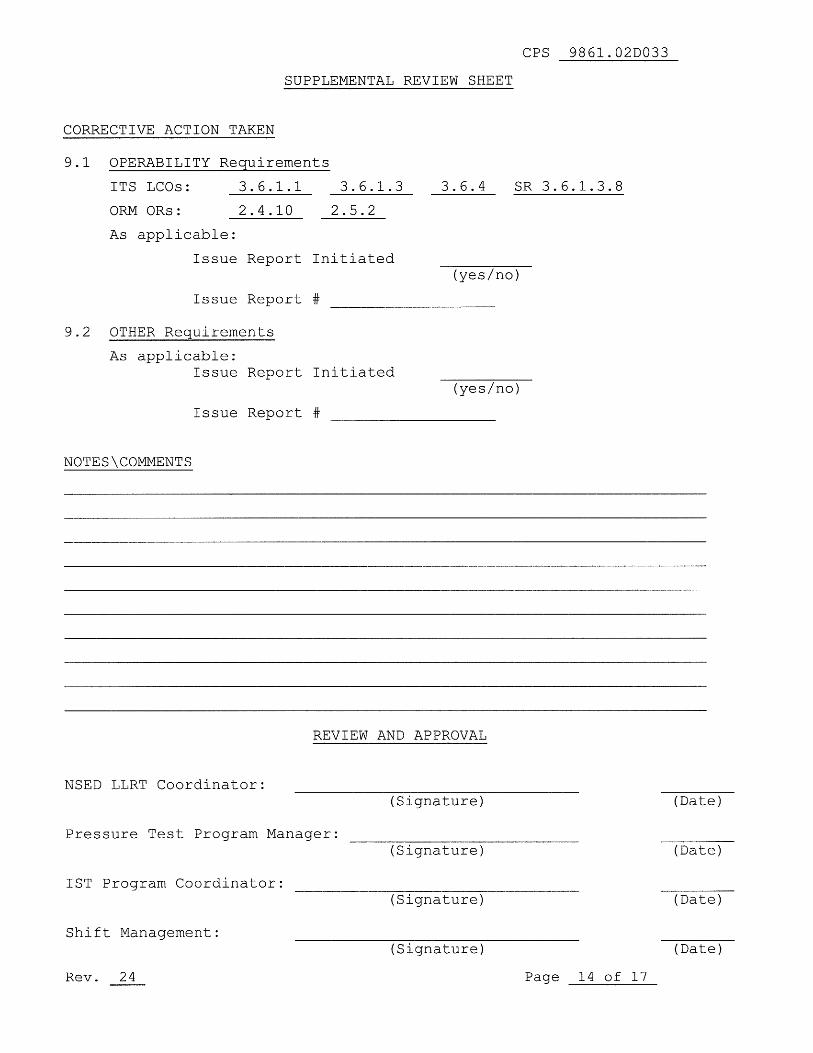
CPS 9861.02DO33
SUPPLEMENTAL REVIEW SHEET
CORRECTIVE ACTION TAKEN
9.1 OPERABILITY Re uirements
ITS LCOs:
3.6.1.1
3.6.1.3
3.6.4
SR 3.6.1.3.8
ORM ORs:
2.4.10
2.5.2
As applicable:
Issue Report Initiated(yes/no)
Issue Report #
9.2 OTHER Requirements
As applicable:Issue Report Initiated
(yes/no)
Issue Report #
NOTES\COMMENTS
REVIEW AND APPROVAL
NSED LLRT Coordinator:
Pressure Test Program Manager:
1ST Program Coordinator:
Shift Management:(Signature)
(Date)
Rev. 24
Page 14 of 17
(Signature)
(Signature)
(Date)
(Date)
(Signature) (Date)
CPS 9861.02D033
SUPPLEMENTAL REVIEW SHEET
CORRECTIVE ACTION TAKEN
9.1 OPERABILITY Requirements
ITS LCOs: 3.6.1.1
2.4.10
3.6.1.3
2.5.2
3.6.4 SR 3.6.1.3.8
ORM ORs:
As applicable:
Issue Report Initiated (yes/no)
Issue Report #
9.2 OTHER Reguirements
As applicable: Issue Report Initiated
(yes/no)
Issue Report #
NOTES\COMMENTS
REVIEW AND APPROVAL
NSED LLRT Coordinator: (Signature)
Pressure Test Program Manager:
1ST Program Coordinator: (Signature)
Shift Management: (Signature)
Rev. 24 Page 14 of 17
(Date)
(Date)
(Date)
(Date)
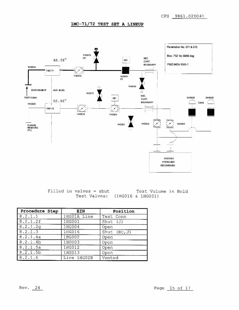
CPS 9861.02D041
1MC-71/ 72 TEST SET A LINEUP
Penetration No. 071 & 072
Elev. 752' Az 58/66 deg
P&ID M05-1063-1
AZ.58°SEC.
CONT.
BOLNDARY
f-^MO
FLANGE
REMOVED
(iV)
1HG02B
I
OFIG01SA
HYDROGEN
RECOMBINER
Filled in valves = shut
Test Volume in BoldTest Valves:
(1HGO16 & 1HGO01)
Procedure Step EIN Position8.2.1.1 1HG01A Line Test Conn
8.2.1.2f 1HGO01 Shut
(J)8.2.1.2g 1HGO04 Open8.2.1.3 1HGO16 Shut
(RC,J)8.2.1.4a 1HGO02 Open8.2.1.4b 1HG003 Open8.2.1.5a 1HGO12 Open8.2.1.5b 1HGO13 Open8.2.1.6 Line 1HG02B Vented
Rev. 24
Page 15 of 17
CPS 9861.02D041
i CONTANr.ENT
TEST CONN
AZ.S8°
lMC-71/72 TEST SET A LINEUP
1HG016 (J) '~-I
,MO : SEC. CONT.
i BOLNDARY
~_-+I r:x~r i .f--! ---:-_' __ I '"""'1 : / .j..; --.... ------+'i ! I '----i ----'1
~ i~: I I
1HG001 ~' (J) ( )
1HG020
L1 SEC.
100012
AUX. BlDG. 1HG017
BOUN()II.RY , : AZ. 66° CONT.
Penetration No. 071 & on
Bev. 752' k 58166 deg
P&ID M05-1063-1
1HG02B
IV"" /1 +-1 ----'-__ ,1, r//l,l·\----r---"---''-----~! -+ __ ---, 'r-------I V j I : ~; Ii ,---------j 1 MC·72
-------' 1HG013 1HGOO4 ,
~ FLANGE REMOVED (TV)
Procedure 8.2.1.1 8.2.1.2f 8.2.1.2g 8.2.1.3 8.2.1.4a 8.2.1.4b 8.2.1.5a 8.2.1.Sb 8.2.1.6
Rev. 24
Filled in valves = shut Test Valves:
Step EIN IHG01A Line Test 1HGOO1 Shut 1HGOO4 Open 1HG016 Shut IHGOO2 Open 1HGOO3 Open 1HG012 Open IHG013 Open
1HG021 1HG002
-!-
~ U
\, )
I ~
OHG01SA
HYDROGEN
RECOMBINER
1HGOO3
Test Volume in Bold (lHG016 & 1HGOOl)
Position Conn ( J)
(RC f J)
Line IHG02B Vented
Page 15 of 17
CAPS
2HG003
(\ .-L • ~
I
I

CPS 9861.02D041
1MC-71/ 72 TEST SET B LINEUP
OHG O1SA
HYDROGEN
HECOMBINER
Filled in valves = shut
Test Volume in BoldTest Valves:
(1HG017 & 1HGO04)
Procedure Step
8.2.2.1
8.2.2.2f8.2.2.2g
8.2.2.3
8.2.2.4a8.2.2.4b
8.2.2.5a8.2.2.5b8.2.2.6
EIN
1HG02B Line
1HGO041HG001
1HG0171HGO02
1HGO03
1HGO121HGO13
Line 1HG01A
Position
Test ConnShut (J)
Open
Shut (RC, J)
OpenOpenOpen
Open
Vented
Rev. 24
Page 16 of 17
CPS 9861.02D041
lMC-71/72 TEST SET B LINEUP
Penetration No. 071 & 072
1HG016 8ev. 752' Az. 58/66 deg
I P&lDM05·1063-1
-'~ CONTAINMENT
~~~ED AUX. BLDG. (fV)
1HG02B
TEST CONN
Procedure 8.2.2.1 8.2.2.2f 8.2.2.2g 8.2.2.3 8.2.2.4a 8.2.2.4b 8.2.2.5a 8.2.2.Sb 8.2.2.6
1HG017 (J)
i
SEC.
CONT.
BOUNDARY
~~I~~~.'I-~--~ ~ 1HG013 1HG004
(J)
1HG021 1HG002
-,-
OHG01SA
HYDROGEN
RECOMBINER
2HG002
•
Filled in valves = shut Test Volume in Bold Test Valves: (lHG017 & 1HG004)
Step EIN Position 1HG02B Line Test Conn 1HGOO4 Shut ( J) 1HGOO1 Open 1HG017 Shut (RC, J) 1HGOO2 Open 1HGOO3 Open 1HG012 Open 1HG013 Open Line 1HG01A Vented
CAPS
Rev. 24 Page 16 of 17
2HG003 / ~'\
•

CPS 9861.02D041
1MC-71 /72 TEST SET C LINEUP
IHGO16
SEC.
CONT.
BOUNDARY
1HG012
1HG001
IHGO20I
AZ .580
CONTAINMENT
AUX BLDG.
1HG017
TEST CONN
AZ . 66°
1 MC-72
i
I
I1HGO 13
1HG004it
IHGO21
TEST CONN
Lb
SEC.
CONT.
BOUNDARY
PertetraGon No. 071 & 072
a ev. 75Z Az 58'66 deg
P& D M05-1063-1
2HGO02
2HG003
CAPS
7--t -1 N 01HGO02
1HGO03
TJ
J
DHGOISA
HYDROGEN
RECOMBMJER
Filled in valves = shut
Test Volume in BoldTest: (Closed Loop)
Procedure Step EIN Position8.2.3.1 1HG01A Line Test Conn8.2.3.1 1HG02B Line Test Conn8.2.3.2e 1HG004 Open8.2.3.2f 1HGO01 Open8.2.3.3a 1HGO16 Shut8.2.3.3b 1HGO17 Shut8.2.3.4a 2HGO02 Shut8.2.3.4b 2HG003 Shut8.2.3.5a 1HGO02 Open8.2.3.5b 1HGO03 Open8.2.3.6a 1HG020 Shut8.2.3.6b 1HGO21 Shut8.2.3.7a 1HGO12 Open8.2.3.7b 1HGO13 Open
Rev. 24
Page 17 of 17
CPS 9861.02D041
IMC-71/72 TEST SET C LINEUP
1HG016 I----r SEC.
~ CONT.
~ BOltolDARY
Il"']! 1~71 L-J .... - ....... , /" +-1 ---.... -----+~i-: -~I-I --I ...
AUX. BLOO.
1I-G012 1HG001 i
1HG020
~ ~
SEC.
Penetrn50n No. 071 & 072
8ev. 752: Az 58/66 deg
P&lO M05-1063-1
2HG002
• AZ. 66° CONT.
i CONTAINMENT
TEST CONN :iG017
!MOI
r1HG02B
r-11-MC-+-_17-2 -----""""1 ..... --....,itl); t~+-: _ .......... __ BOUIIIIIII:N~DA~R ... ' .... __ ..
1HGO 13 1HGOO4
1HG002 (' """,">1
{~ -----r-~I • i 1HG021 &:I ~
TEST CONN
Procedure 8.2.3.1 8.2.3.1 8.2.3.2e 8.2.3.2f 8.2.3.3a 8.2.3.3b 8.2.3.4a 8.2.3.4b 8.2.3.Sa 8.2.3.Sb 8.2.3.6a 8.2.3.6b 8.2.3.7a 8.2.3.7b
oI-G01SA
HYDROGEN
RECOMBINER
Filled in valves = shut Test Volume in Bold Test: (Closed Loop)
Step EIN Position 1HG01A Line Test Conn 1HG02B Line Test Conn 1HGOO4 Open 1HGOO1 Open 1HG016 Shut 1HG017 Shut 2HGOO2 Shut 2HGOO3 Shut 1HGOO2 Open 1HGOO3 Open 1HG020 Shut 1HG021 Shut 1HG012 Open 1HG013 Open
CAPS
Rev. 24 Page 17 of 17
2HG003 (----.... "1 ~,-
~ •