CLASSROOM DESIGN GUIDELINES - Classroom Technology
22
REV:03 – JUNE2008 18A - 01 © University of Washington – Classroom Support Services 2008 U NIVERSITY OF W ASHINGTON GENERAL ASSIGNMENT CLASSROOMS Classroom Support Services Design Guide Basis of Design General use instructional rooms are essential components in the University of Washington’s instructional mission. Instructional rooms have increasing complex design and technical requirements. This section is intended to inform the University’s professional design consultants of the University’s expectations and requirements for instructional spaces. Background Classroom Support Services (CSS) is a department of Undergraduate Academic Affairs. CSS is responsible for, and manages, the University of Washington Seattle campus general use classrooms. The design guidelines for classrooms that follow were developed by CSS and reviewed and endorsed by a variety of faculty committees including the Faculty Senate’s Council on University Facilities and the Council on Educational Technology. Programming The following Design Goals have been established for University of Washington instructional rooms: 1) To provide the most effective learning environments based on desired pedagogy; 2) To provide an environment designed to enhance a student’s ability to understand, observe and participate in active learning; 3) To provide an environment that is comfortable for students and instructors as well as durable, reliable, and easy to maintain; and, 4) To provide a room that is easy for faculty and student equipment operators to use through standardization of controls, layouts, and equipment. The FEPG (Rev. 10/94) was developed by institutions of public higher education in the State of Washington to assist in planning and evaluating the need for campus facilities. The section devoted to classrooms is summarized here. The complete Guide is available from UW’s Capital and Space Planning Office (CASPO). 1) Classrooms and Classroom Support Spaces are generally institution-wide resources. The term “classroom” includes not only general purpose classrooms, but also auditoria, seminar rooms, breakout rooms and other rooms used primarily for scheduled non-laboratory instruction. Classroom facilities include any support rooms that serve the classroom activity. 2) Average standard room use is assumed to be 30 hours of scheduled weekday, daytime use per week. (Based on a 9-hour period beginning with the first hour for regularly scheduled classes.) 3) Average standard room fullness is assumed to be 70 percent of the stations occupied during hours of scheduled daytime use. 4) Average weekly hours per station is calculated at 21 hours of scheduled weekday, daytime use per station per week (30 hours x 70 percent fullness = 21 hours per station.) 5) Design standards for classrooms depend on the size and shape of the room, the intended capacity, the type of furniture desired, the teaching pedagogy required and the level of technological equipment and furniture incorporated into the room.
Transcript of CLASSROOM DESIGN GUIDELINES - Classroom Technology

REV:03 – JUNE2008 18A - 07
© University of Washington – Classroom Support Services 2008
UNIVERSITY OF WASHINGTON GENERAL ASSIGNMENT CLASSROOMS Classroom Support Services Design Guide
Design Criteria – Technology Room Types
General
University of Washington instructional rooms (i.e., classrooms, breakout rooms, seminar rooms, computer classrooms, case study rooms, and auditoria) are also categorized into technical room types by: 1) The level of technology-access provided,
2) The portability or permanence of equipment in the room, and
3) The need for ancillary support space.
All instructional rooms have some level of connectivity to the outside world if only via standard University voice/communication lines and cable TV systems. Instructors must be able to obtain/use media/data from sources located outside the physical constrains of the classroom, generally display/share media and/or data with their students and engage students in active exchanges.
Instructional rooms cannot be categorized solely on room configurations (e.g., whether the room is a seminar room or an auditorium) but are classified on room functionality ratings, as described below. Room functionality is supported by 3 general layers of infrastructure:
1) Infrastructure associated with traditional classroom optical equipment and technologies, (e.g., overhead projectors.)
2) Infrastructure associated with modern multi-media and digital equipment and technologies, (e.g., hi-fidelity sound systems, PA/voice-enhancement, student microphones, video/data display equipment, program playback equipment, etc.
3) Infrastructure is required to integrate each room system and communications outlets with the building control points and/or the campus-wide network (e.g., teleconferencing, video presentation, video production/post-production, television broadcast.)
Technical support rooms for classrooms may include: 1) Centrally located control room that serves a cluster of classrooms, and
2) Master control room which serves the whole building.
Technology Levels
Technology categories typically include the features of the previous room category. Specifics for technology and systems will depend on the ultimate size and shape of the individual classrooms as well as the desired functionality of the room. General guidelines for the location and installed infrastructure are described below.
Level A: Standard Technology Room
“Standard” classrooms are often, but are not exclusively, associated with smaller instructional rooms such as seminar rooms, conference rooms and breakout rooms where limited technology/equipment is generally available. The primary functionality of the room is non-technology based (e.g., discussions, etc.) In additional to an installed projection screen in-room equipment is limited and may consist of a flat panel, TV monitor, a DVD player and an overhead projector. Basic classrooms generally will not have equipment control systems
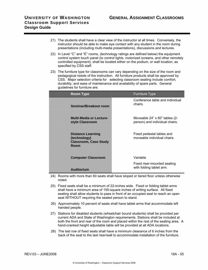
18A - 08 REV:03 – JUNE2008
© University of Washington – Classroom Support Services 2008
UNIVERSITY OF WASHINGTON GENERAL ASSIGNMENT CLASSROOMS Classroom Support Services Design Guide
motorized screens or shades, or built-in data projection equipment or program sound equipment.
Permanent infrastructure includes:
1) Power outlets and communication outlets,
2) Conduit pathway from front wall to rear wall,
3) Conduit pathway from wall/ceiling mounted flat panel monitor (at 96” AFF) to audio/video outlet (at 18”AFF),
4) Conduit pathway from room to building cable tray system, and
5) Cable/TV outlets (if applicable).
Other considerations include:
1) Minimum NC ratings: 0 – 59 seats: 30 – 35; 60 – 149 seats: 25 – 30; 150+ seats: 20 – 25.
2) All “A” level rooms should have standard white/chalkboards, tackboards, window shades, general room lighting as described in Part 3 requirements,
3) In addition to wall outlets, all “A” level rooms may have co-located floor power/communication outlets,
4) Appro priate connections, pullboxes, equipment support brackets,
5) Conduit and box sizes should correspond to the Technology and Infrastructure summary charts found in the Addendum to this section.
Level C: Enhanced Service Room
Level C, “Enhanced Service” classroom, can typically be described as a classroom that meets modern teaching and multi-media requirements. These classrooms are found in all sized rooms, ranging from small 20-seat classrooms to large auditoria. The room technology includes permanently installed equipment for multi-media presentations and some infrastructure for ad hoc distributed (distance) education. Additional attributes of Enhanced Level rooms include equipment and room control systems, permanently installed data/video projectors, motorized projection screens, and overhead projectors. Larger capacity rooms will also include video/audio capture equipment for CSS controlled podcasting and/or screencasting.
The control-center for in-room equipment may be an equipment closet(s) and/or a teaching podium. The designed element needs to contain instructor operated equipment (e.g., VCR/DVD, audio cassette players, etc.) as well as systems equipment (e.g., control equipment, amplifiers, patch panels, etc.) The casework act as the local control point for classroom infrastructure and is the general connection point for the room’s internal and external infrastructure. Equipment closets, like the teaching podia should be sized to hold standard rack-mounted equipment components. If used, the equipment closets should be either recessed in a convenient location for the instructor to access the internal equipment. Essential elements for both closets and podia include:
1) Pull-out racks for equipment maintenance.
2) Standard, not cabinetry doors.
3) Security locking hardware, keyed to CSS keys sequence.
4) Electrical power for equipment.
REV:03 – JUNE2008 18A - 09
© University of Washington – Classroom Support Services 2008
UNIVERSITY OF WASHINGTON GENERAL ASSIGNMENT CLASSROOMS Classroom Support Services Design Guide
5) Rack-mounted working lights.
6) Cooling for equipment (active or passive depending on the density of the equipment and ventilation features of the casework and classroom.)
Permanent infrastructure includes:
1) Power outlets and communication outlets.
2) Appropriate floor boxes to support power, data and audio-visual equipment at instructor’s podium.
3) Conduit pathway from front wall to rear wall.
4) Conduit pathways to support equipment control system, permanently installed audio-video equipment (e.g., data projectors, etc.).
5) Conduit pathways to support portable and/or permanent cameras.
6) Power to support portable broadcast lighting needs.
7) Conduit pathways from podium floor box to equipment closet(s) if applicable and to building cable tray system.
8) Cable/TV outlets (if applicable).
Other considerations include:
1) Minimum NC ratings: 0 – 59 seats: 25 – 30; 60 – 149 seats: 25 – 30; 150+ seats: 20 – 25.
2) All “C” level rooms should have standard chalk/white boards, tackboards, window shades, general room lighting as described in Part 3 requirements.
3) In addition to wall outlets, all “C” level rooms should have co-located floor power/communication outlets to support portable equipment.
4) Power to support ceiling mounted video/data projector and other in-room equipment or furnishings (e.g., document cameras, motorized projection screen, motorized marker boards, motorized window coverings, etc.).
5) Conduit and low voltage wiring to support public address system and podium microphone (large or noisy rooms only).
6) Equipment/conduit to support stereo sound or higher quality system for program audio systems.
7) Appro priate connections, pullboxes, equipment support brackets.
8) Conduit and box sizes should correspond to the Technology and Infrastructure charts found in the Addendum section.
Level E: Distance Learning/Broadcast Room
Distance Learning/Broadcast” classroom are designed to meet multi-media requirements and distributed (distance) education needs. These classrooms are sometimes associated with larger rooms but like “Enhanced Service” rooms, can be found in all sizes. The major difference between Level “C” and Level “E” rooms are found in the acceptable noise levels (NC 30-35 vs. 20-30), the permanently installed broadcast equipment and ancillary equipment and the need for associated broadcast control rooms and supporting facilities. Additional attributes of Distance Learning rooms include equipment and room control
18A - 010 REV:03 – JUNE2008
© University of Washington – Classroom Support Services 2008
UNIVERSITY OF WASHINGTON GENERAL ASSIGNMENT CLASSROOMS Classroom Support Services Design Guide
systems, permanently installed data/video projectors, audience microphones, document cameras, motorized projection screens, and overhead projectors.
As in Level “C” rooms, the control-center for in-room equipment are equipment closets and/or teaching podium designed to contain instructor operated equipment (e.g., DVD players, audio cassette players, TV monitors, etc.) as well as systems equipment (e.g., control equipment, amplifiers, patch panels, etc.) The control-center for broadcasting is located in an adjacent control room that is sized appropriately to support the number of classrooms in the building. Special needs of Control rooms are found in the Voice/Data/Video Communication information elsewhere in the UW Technology Design Guide.
In-room equipment closets act as the local control point for classroom infrastructure and are the general connection point for the room’s internal and external infrastructure. Equipment closets should be recessed into the front wall of the room and sized to hold standard rack-mounted equipment components. Essential elements include:
1) Pull-out racks for equipment maintenance.
2) Standard, not cabinetry doors.
3) Security locking hardware, keyed to CSS keys sequence.
4) Electrical power for equipment.
5) Rack-mounted working lights.
6) Active cooling for equipment.
Permanent infrastructure includes:
1) Power outlets and communication outlets.
2) Appropriate floor boxes to support power, data and audio-visual equipment at instructor’s podium.
3) Conduit pathway from front wall to rear wall.
4) Conduit pathways to support equipment control system, permanently installed audio-video equipment (e.g., data projectors, etc.).
5) Conduit pathways to support permanently installed broadcast cameras.
6) Conduit and cabling for student 2-way distance learning microphones.
7) Conduit pathways from podium floor box to equipment closet(s) to Control Rooms and building cable tray system.
8) Cable/TV outlets (if applicable).
Other considerations include:
9) All “E” level rooms should have an NC rating of less than NC 25 with NC 20 preferred (all size rooms).
10) All “E” level rooms should have standard chalk/white boards, tackboards, window shades, general room lighting as described in Part 3 requirements.
11) Special consideration should be given to room finishes (to reduce glare and provide greater acoustical properties) necessary for quality broadcasting.
12) In addition to wall outlets, all “E” level rooms should have co-located floor power/communication outlets to support portable equipment.
REV:03 – JUNE2008 18A - 011
© University of Washington – Classroom Support Services 2008
UNIVERSITY OF WASHINGTON GENERAL ASSIGNMENT CLASSROOMS Classroom Support Services Design Guide
13) Provide power to support ceiling mounted video/data projector and other in-room equipment or furnishings (e.g. motorized projection screen, motorized marker boards, motorized window coverings, etc.).
14) Provide conduit and low voltage wiring to support public address system/broadcast audio via podium microphone or wireless microphone.
15) Provide equipment/conduit to support high quality stereo sound system for program audio systems.
16) Provide power to support permanent broadcast quality lighting.
17) Conduit and box sizes should correspond to the information in the Technology and Infrastructure summary charts found in the Addendum to this section.
18) In some cases, Level “E” rooms will also include conduit to individual seat locations for power, data connections and/or Student Response System capabilities.
Design Criteria - Support Spaces
• Equipment Storage Room
1) In new construction, a dedicated A/V equipment storage room shall be provided to support general use instructional rooms. The CSS equipment storage room is a separate room. The room shall be approximately 100 square feet in total size with a height clearance of 7 feet throughout the space (no low beams or duct work). The minimum acceptable dimension of the storage room is 7 feet by 14 feet; 10’x10’ or 12’x8’ is preferred.
2) The equipment storage room shall be located as close as possible to the main concentration of instructional rooms in the building.
3) The CSS storage room shall have fluorescent lighting and ventilation. The door into the storage room shall be at least 42” wide with the door swinging out to allow storage inside the room.
4) Provide direct access to the storage room from a public hallway; avoid storage rooms opening off classrooms or other normally occupied rooms.
5) All instructional equipment storage rooms shall be keyed to CSS equipment master key sequence, not the building master key. A minimum of 4 keys per room shall be provided to CSS staff.
• Master Control Room: See the Voice/Data/Video Communications section.
Projection Booth
1) All auditoria shall have a projection booth built in at the rear of the room to support front projection. Rear projection designs must be reviewed and approved by CSS staff prior to inclusion in the building design.
2) Projection booth walls shall be constructed to meet STC-50. Booth minimum size of is 10 feet wide by 6 feet deep. Booth entrance shall be ADA accessible. Entrance to booth shall be without entering main auditorium seating areas.
3) Projection Booths must be locked with system to accommodate CSS key system as specified during Design Development stages of the project. Current (May, 1998) standard lock is the Schlage CL-100PB-E-626 keyway.
18A - 012 REV:03 – JUNE2008
© University of Washington – Classroom Support Services 2008
UNIVERSITY OF WASHINGTON GENERAL ASSIGNMENT CLASSROOMS Classroom Support Services Design Guide
4) The booth shall have a single projection window, 32-inches high and as wide as practical. The window shall be centered on the projection screen with the window sill at 48-inches AFF. The window glass shall be made of ¼-inch (minimum) float glass and placed perpendicular to the floor.
5) The projection booth shall have a projection shelf for equipment. The shelf shall be constructed of 1 ½-inch thick plywood (or equivalent) and be a minimum of 24 inches deep. The shelf shall run the entire length of the projection window and be supported by a minimum of three support points. The shelf shall be finished with a matte finished dark colored plastic laminate.
6) The front edge of the shelf (nearest the glass) shall be even with the window sill. The rear edge of the shelf shall be tilted up a minimum of 2 inches. A minimum 3-inch space should be included between the front edge of the shelf and the wall for cables.
7) Provide a second shelf below the projection shelf at 12 inches AFF for equipment storage.
8) Provide a separate, lockable storage cabinet that is at minimum 12 inches high by 48 inches long by 24 inches deep for expensive and/or portable equipment. Key this cabinet separately from the projection room lock.
9) Extend a surface metal raceway, equivalent to Wiremold 3000, the full length of the wall below the projection shelf at 24-inches AFF with 4 evenly spaced duplex receptacles.
10) The center two receptacles should be on one dedicated 20 amp circuit and the outside two receptacles on a separate relay-controlled dedicated 20 amp circuit. (Note: All receptacles should be relay controllable, if desired by CSS staff.)
11) Provide a duplex receptacle located away from the shelf and door for equipment not located on the shelf (e.g., audio system components) and a double duplex receptacle centered on the rear wall of the booth (all at 18-inches AFF) on a third dedicated 20 amp circuit.
12) Extend a separate surface metal raceway at 30 inches AFF, equivalent to Wiremold 3000 or low voltage wiring. The raceway should extend the full length of the wall below the projection shelf and connect with terminal cabinet. Provide conduit connections from this cabinet as specified in the Addendum.
13) The terminal cabinet should be located on the wall opposite the booth door. The cabinet should be a minimum of 30 inches wide by 42 inches high by 6 inches deep. The cabinet should have a lockable door to limit access to controls and equipment. The cabinet should be provided with a relay controlled dedicated 20 amp circuit.
14) The projection booth should have two lighting systems, a general fluorescent system for maintenance and set up, and a dimmable downlight system for use when the classroom is darkened. The downlights should be mounted near the front wall and designed to concentrate light on the projection shelf without shining into the audience. The manual dimmer switch should be located so it can be reached by an equipment operator without leaving the equipment. The dimmer switch should be located as far away from the terminal cabinet as possible to reduce interference. The fluorescent light should be controlled with the switch by the door.
15) The breaker panel, classroom control cabinet, and notetaking light motorized dimmer should be located on the back wall of the projection booth, with the dimmer

REV:03 – JUNE2008 18A - 013
© University of Washington – Classroom Support Services 2008
UNIVERSITY OF WASHINGTON GENERAL ASSIGNMENT CLASSROOMS Classroom Support Services Design Guide
at the opposite end of the room from the terminal cabinet to reduce interference. Preferred equipment for relay cabinet is GE RB-3 (or larger as required). Preferred equipment for motorized dimmer is Lutron MCD-120-2000 (2000 watt) or newest model approved by CSS technical staff.
Audio-Visual Systems
1) Specialty systems designs should include all audio-visual designs. Audio-visual systems details should not be repeated on communication or electrical drawings. Provide line diagrams of audio visual systems in Design Development drawings. Provide construction drawings showing actual infrastructure locations, conduit sizes and details.
2) Larger classroom and auditorium ceilings should utilize hard surfaced slopes or steps designed to improve sound at the rear of the room. The front wall should utilize hard surfaces. Sound dampening materials should be applied to the rear and side walls as required. Side walls should not be parallel, but should fan out toward the rear of the room.
Equipment and Room Control System
1) The equipment and room control system will be determined based on existing systems on the UW Seattle campus and specific controls needs for the individual classrooms. Crestron systems are currently in use at the Seattle campus for most Level “C” and “E” classrooms. Other, more basic systems are also used for smaller, less complex equipment rooms and may be proposed for consideration by CSS staff.
2) Instructional rooms that merit equipment and room controls are identified in Technology Room Types.
3) Rooms with equipment control systems should include infrastructure to support both a hardwired touch panel (in the podium or a wall mounted application) as well as wireless remote control units. Wireless units require a storage location in the room that can be secured and that provides power to recharge the remote’s batteries.
Audio System
1) Instru ctional rooms that merit audio systems are identified in Technology Room Types.
2) In-room Public Address (PA) systems should include capabilities to support:
1) A hard-wired microphone located at the podium,
2) A wireless microphone,
3) Auxiliary input(s) and record output(s) to enable easy audio recording of the speaker.
3) In addition to standard program audio equipment (e.g., audio-cassettes, audio-CDs, video tapes, DVDs, etc.) the program audio system should support computer generated audio (e.g., multi-media presentations) from the podium and other emerging technologies.
4) Special audio needs required for distance learning/broadcast should be incorporated into the room design with special consideration given to the need for student microphones and audio requirements at the distant site.
18A - 014 REV:03 – JUNE2008
© University of Washington – Classroom Support Services 2008
UNIVERSITY OF WASHINGTON GENERAL ASSIGNMENT CLASSROOMS Classroom Support Services Design Guide
5) Rooms with program audio systems and rooms with PA systems should be controlled by the equipment control touch panel or other controls as approved by CSS staff.
6) The audio system components will be located in the in-room equipment closet, teaching podium, projection room and/or control room. These systems should be accessible only to trained technicians and not the general public.
7) The audio mixer(s) or mixer/amplifier(s) should provide a minimum of 6 input channels, with plug-in input modules. Preferred standard equipment is TOA 900 Series or newest model. All equipment must be approved by CSS staff.
8) Assisted listening systems should be incorporated into classrooms and auditoria based on federal ADA legislation and special City of Seattle DPD approval for using portable equipment systems in UW Seattle classrooms.
9) Direct, two-way communication between the instructor and the operator in a projection booth and/or control room should be included in the design.
10) An 8-inch full-range speaker should be provided inside the projection booth and/or control room that is tied into the classroom/auditorium sound system for monitoring the audio system from the projection booth.
11) Full control over the room’s audio sound system should be available in the projection booth/control room. Individual volume controls shall be provided for auxiliary input as well as specialized program audio (e.g., DVD, computer audio, etc.) and record output.
12) A master volume control for public address sound reinforcement and program audio shall be provided.
13) The auditorium speaker system should be carefully designed for the space to provide uniform coverage of +/- 2DB, 80 to 8000 Hz minimum over the entire seating area of the auditorium for both sound reinforcement and sound reproduction.
Chalk/Marker Board
1) Both chalkboards and marker boards (i.e., “white” boards) are used in University of Washington instructional rooms. CSS staff will specify board type during the design development stage of the project.
2) All chalk/marker boards shall be porcelain/ceramic on steel products. Preferred manufacturer is Alliance; all products must be approved by CSS staff. Preferred color is white to light-gray.
3) All chalk/marker boards will include a tack strip along the top edge and chalk/pen tray at the bottom edge.
4) All instructional rooms will have a minimum of 16 linear feet of chalk/marker boards. The boards should be a minimum of four feet high with the bottom edge of the chalk tray 36 inches AFF.
5) Sliding boards are acceptable up to three boards deep (i.e. one stationary and two sliding sections) to increase the overall amount of board space available for instructors. If used, sliding boards should always have slide stops in the tracks to prevent boards from moving beyond the general reach of the average-height instructor.

REV:03 – JUNE2008 18A - 015
© University of Washington – Classroom Support Services 2008
UNIVERSITY OF WASHINGTON GENERAL ASSIGNMENT CLASSROOMS Classroom Support Services Design Guide
6) Chalk/marker boards are generally omitted from large auditoria since students cannot read information on the board. However, when desired, the boards should be included when directed by CSS staff.
7) Portable chalk/marker boards are not allowed in University of Washington instructional rooms.
8) A small tackboard area may be included in the classroom.
9) Tackboards should also be provided in the hallways adjacent to classrooms for posting grades, class changes, etc.
10) A portion of the total chalk/marker boards should be uncovered and available for use by the instructor when the projection screen(s) are lowered.
Clocks and Bells Refer to Electrical – Section 16Y, Clock and Bell Systems for general requirements.
Communications
1) Service should comply with UW standards and specifications shown in the Voice/Data/Video Communications design standards.
2) Standard UW communications outlets are required in general use instructional rooms.
3) All rooms will have a minimum of two standard outlets. The priority for locations in classrooms is as follows:
1. At podium, or if not applicable, at the front teaching wall;
2. Adjacent to the data projector;
3. At the equipment closet, or if not applicable at the projection booth;
4. At the back wall (opposite the teaching wall).
Electrical Services Refer to the Facilities Services Design Guide, Electrical – Section 16E, Building Power Distribution. (Information maintained by Classroom Support Services.)
• Lighting and Lighting Controls Refer to Facilities Services Design Guide, Electrical – Section 16U, Lighting. (Information maintained by Classroom Support Services.)
Equipment and Cable Plant
1) A separate equipment and cable plant design is required for University instructional rooms. The A/V designer will work with CSS staff to complete the equipment design including a matrix or schedule of room types and technical categories, functional equipment required by room and line drawings of the AV system.
2) An integrated Purchase/Install process may be used to purchase and install all instructional room audio visual equipment and systems at the discretion of the UW’s Project Manager. If applicable, the contractor for this phase of the project must meet minimum qualifications set forth in the equipment/cable plant design. The integrated purchase/install contractor will purchase all equipment as specified by CSS and design consultant, install all equipment and systems, test equipment and systems and train CSS technical staff on operation and maintenance of the equipment and systems.
18A - 016 REV:03 – JUNE2008
© University of Washington – Classroom Support Services 2008
UNIVERSITY OF WASHINGTON GENERAL ASSIGNMENT CLASSROOMS Classroom Support Services Design Guide
3) All equipment and cable will meet standards as specified by CSS staff and design consultant. All substitutions must be approved prior to installation. All requests for substitution must include an on-site test of the actual equipment requests by the contractor.
4) All audio visual cabling will be U.L. approved and be free of defects and splices.
Equipment Closet
1) Equipment closet(s) may be required in Level “C” and “E” instructional rooms as noted in Technology Room Types.
2) The equipment closet(s) acts as a hub for the internal room infrastructure. Conduit ranging in size from 1-inch to 2-inch in diameter will run from equipment in the room (i.e., from the podium, the ceiling data projector, the speakers, the microphones, etc.) to the cabinet(s). Sufficient space must be provided to accommodate the necessary conduit.
3) As the room hub, the equipment closet(s) will also have conduit to support rooms (e.g., to a projection room, control room, or master control room) located outside the classroom but needed to support instructional activities.
4) The number and size of the closets will be determined by the number of equipment pieces to be housed and capacity of the podium (if any). Typically, rooms will require one closet to accommodate the equipment. If multiple closets are needed interconnecting conduit is required between the closets.
5) The exact size of the closet will be determined in conjunction with the design team and staff from CSS. Minimum width and depth clearance of the closet will be sufficient to hold a sliding, 24”-wide equipment rack that is extended for maintenance.
6) The equipment closet(s) should be recessed into the wall with the front door flush with the room wall. An instructor should be able to quickly move from behind the podium to the equipment closet without crossing the entire front of the room. If possible, rear access from the corridor is desirable for equipment maintenance.
7) Doors for the closet(s) should be standard 1-hour rated doors with secure locking mechanisms to prevent theft of the equipment. The closet(s) should be keyed per CSS instructions.
8) Until further notice, lock sets for equipment closets must accommodate the Schlage CL-100PB-E-626 keyway.
9) Equipment needed by the instructor (e.g., the DVD player, CD-player, Blue Ray player etc.) should be located separately from the systems equipment (e.g., mixers, amplifiers, etc.) Access to the systems equipment is limited to CSS technical staff and not to instructors/students and thus should be keyed differently from the user-accessible equipment.
10) In rooms with a single equipment closet, the control equipment and instructor equipment should be separately located within the closet. The closet should secure the control equipment separately from the instructor equipment.
11) Sufficient power to operate a fully loaded equipment rack should be provided on back wall of equipment closet.
12) A communications/Ethernet outlet (adjacent to power), should be provided on back wall of equipment closet.

REV:03 – JUNE2008 18A - 017
© University of Washington – Classroom Support Services 2008
UNIVERSITY OF WASHINGTON GENERAL ASSIGNMENT CLASSROOMS Classroom Support Services Design Guide
13) Cooling should be provided based on a fully loaded and operating equipment rack. Electronic equipment located in the closet cannot be cooled sufficiently by general room air-flow and requires mechanical cooling.
14) Temperature inside closet with equipment powered and running and doors closed and locked should equal ambient air temperature inside the instructional room within 5-7 degrees F.
15) Standard rack unit ventilation spaces are required between each unit mounted in the rack. Equipment must be mounted with security screws. Equipment should also be secured with padlocked security cables to prevent theft.
16) Rack units should be securely fastened into the equipment closet. Rack units must have slide-out capability to allow service to back of equipment. Units must also include secure cable management system to allow equipment to slide out for maintenance.
17) Equipment within the rack units must be secured with security screws and, if needed, separately cabled with security cables to prevent thefts.
18) Prior to installation all equipment serial numbers, manufacturer information and model information must be provided to CSS in an easy to use electronic spreadsheet for inventory purposes.
Finishes Refer to the Facilities Services Design Guide, Architectural – Section 9B, Finishes for general information. 1) Painted surfaces in classrooms should be durable to reflect the high occupancy
and usage of these learning spaces.
2) The reflectance values and color schemes for classrooms should be developed in conjunction with CSS. General guidelines for reflectance values in classrooms are:
Ceilings 70-90%
Walls 40-6 0%
Floors 30-5 0%
Desktops 2 0-30%
Chalk/Marker boards 20-30%
3) Floors in classrooms should be hard surfaces unless otherwise noted. All floors should be free of cracks or other defects. Selection of flooring should include consideration of sustainable products, acoustic properties of the flooring, and ease of maintenance by UW staff.
4) Carpet is not allowed without prior concurrence of CSS staff.
5) Chair rails should be applied to classrooms with moveable tables and/or chairs. Rails should match the architectural design of the room and installed to match the standard height of chairs (approximately 25-27” AFF.)
Moveable Overhead Projector Power
18A - 018 REV:03 – JUNE2008
© University of Washington – Classroom Support Services 2008
UNIVERSITY OF WASHINGTON GENERAL ASSIGNMENT CLASSROOMS Classroom Support Services Design Guide
1) Provide power in floor for overhead projectors and/or document cameras. Power should be located approximately ¾ of the screen width from the front wall. If only one overhead projector is specified the floor box should be centered at the mid-point of the projection screen. If two projectors or document cameras are specified with a single screen, locate the power approximately ¼ the screen width on each side of the center of the screen.
Podium/Lectern
1) Podium should be based on standard UW “smart podium” design. Line drawings are available from CSS. Architectural design features may be added by design consultants as long as technical requirements for the podium are met.
2) The podium typically should be located on the instructor’s left side (when facing the class) and angled toward the opposite rear corner of the room, to allow the instructor to face the audience, use the chalk/marker board and still view the projection screen. The podium should not block the students’ view.
3) The teaching podium should be secured in its location but designed to enable CSS or authorized staff to move the podium for maintenance. If feasible provide retractable wheels. Provide adjustable leveling feet for podium.
4) The bottom interior of the podium is open to allow access to standard University podium floor box(es). Sufficient clearances are required to allow power cables, communication cables, audio and video cables to transit from the podium to the floor box receptacles without crimping cables.
5) The room control touch panel (if applicable) should be located in a moveable section that can be set on a lower table for ADA compliance. The panel will be hinged to allow instructors to select the appropriate panel viewing angle.
6) Standard connector panels located on the podium top should contain ethernet outlets, audio connections for microphone, aux in, record out, PC and/or Mac laptop plug-in outlets.
7) A duplex power outlet should be provided on the top surface of the podium.
8) Typical podium will have four (4) locks:
A) one (1) that locks the front door (on the instructor’s side of the podium);
B) one (1) on the back door (on the audience’s side of the podium);
C) one (1) on the drawer; and
D) one (1) on the internal drawer compartment.
9) Detailed information on the locks and appropriate keying must be obtained from CSS staff during design development. As of May, 1998, all locks must accommodate a Schlage CL-100PB-E-626 keyway.
10) Wooden tabletop lecterns should be provided Level “A” classrooms in lieu of “smart” podium. Lecterns should be constructed out of ¾ inch high grade plywood with hard finish. Design of lectern should allow for easy carrying. Details of design should be approved by CSS staff.
Projection Screens
REV:03 – JUNE2008 18A - 019
© University of Washington – Classroom Support Services 2008
UNIVERSITY OF WASHINGTON GENERAL ASSIGNMENT CLASSROOMS Classroom Support Services Design Guide
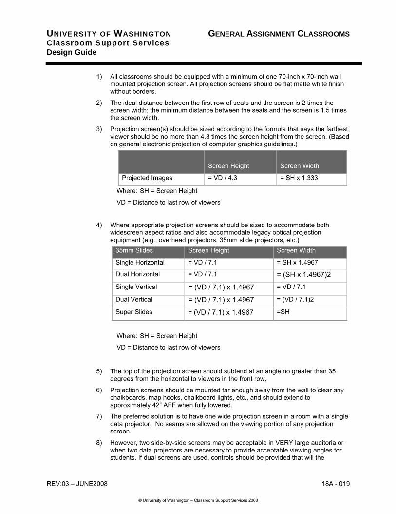
1) All classrooms should be equipped with a minimum of one 70-inch x 70-inch wall mounted projection screen. All projection screens should be flat matte white finish without borders.
2) The ideal distance between the first row of seats and the screen is 2 times the screen width; the minimum distance between the seats and the screen is 1.5 times the screen width.
3) Projection screen(s) should be sized according to the formula that says the farthest viewer should be no more than 4.3 times the screen height from the screen. (Based on general electronic projection of computer graphics guidelines.)
Screen Height
Screen Width
Projected Images = VD / 4.3 = SH x 1.333
Where: SH = Screen Height
VD = Distance to last row of viewers
4) Where appropriate projection screens should be sized to accommodate both widescreen aspect ratios and also accommodate legacy optical projection equipment (e.g., overhead projectors, 35mm slide projectors, etc.)
35mm Slides Screen Height Screen Width
Single Horizontal = VD / 7.1 = SH x 1.4967
Dual Horizontal = VD / 7.1 = (SH x 1.4967)2
Single Vertical = (VD / 7.1) x 1.4967 = VD / 7.1
Dual Vertical = (VD / 7.1) x 1.4967 = (VD / 7.1)2
Super Slides = (VD / 7.1) x 1.4967 =SH
Where: SH = Screen Height
VD = Distance to last row of viewers
5) The top of the projection screen should subtend at an angle no greater than 35 degrees from the horizontal to viewers in the front row.
6) Projection screens should be mounted far enough away from the wall to clear any chalkboards, map hooks, chalkboard lights, etc., and should extend to approximately 42” AFF when fully lowered.
7) The preferred solution is to have one wide projection screen in a room with a single data projector. No seams are allowed on the viewing portion of any projection screen.
8) However, two side-by-side screens may be acceptable in VERY large auditoria or when two data projectors are necessary to provide acceptable viewing angles for students. If dual screens are used, controls should be provided that will the
18A - 020 REV:03 – JUNE2008
© University of Washington – Classroom Support Services 2008
UNIVERSITY OF WASHINGTON GENERAL ASSIGNMENT CLASSROOMS Classroom Support Services Design Guide
instructor to lower/raise both screens simultaneously as well as lower/raise screens as individual screens.
9) Projection screens 10-feet wide or wider should be motorized. When motorized projection screens are used they must be installed with screen fabric centered on front wall and motor offset to one side. A manual switch to operate screen should be located on the side of the screen closest to the teaching podium at 48” AFF.
10) Projection screens should have variable “stop” controls that will allow the screen to be partially raised and/or lowered per instructor’s need.
11) Motorized projection screens should also be controlled via the equipment control system touch panel on the podium in Level “C” and “E” rooms.
12) Preferred manufacturer for projection screens is Stewart with Da-lite as an acceptable alternative. All products must be approved by CSS staff.
REV:03 – JUNE2008 18A - 021
© University of Washington – Classroom Support Services 2008
UNIVERSITY OF WASHINGTON GENERAL ASSIGNMENT CLASSROOMS Classroom Support Services Design Guide
13) Where stationary projection screens are specified (e.g., studio broadcast classrooms) motorized moveable covers should be provided to protect the screen surface when not in use. Design and specification of screen and covers shall be approved by CSS staff.
14) In rooms designated by CSS staff, walls may be used in place of manufactured projection screen. In these cases, the projection wall will be sloped to eliminate keystone from overhead and data projectors. The sloped area will be sized appropriately for the room (i.e. the width of the area should be approximately 1/3 the room depth and the height should be approximately 1/2 the width.)
15) Projection walls, unless otherwise indicated by CSS staff, should be painted with Kelly Moore Paints 550 Super Latex “Dead Flat” or other CSS approved paint.
Security
1) Classrooms, supporting spaces and equipment in classrooms must be designed with security issues in mind.
2) Personal security for students and instructors is essential in design of classrooms. Due consideration must be given by the design team to ensure the safety of the room occupants and the safety of the surrounding environment.
3) Classrooms should be included in any electronic keying system designed for the overall building. Any electronic locking system must allow for flexible schedules to accommodate special weekend events, evening events and non-scheduled maintenance access to the rooms.
4) Keying for locking equipment closets, podium, projection booths, equipment storage and other CSS controlled support spaces must be designed with input from staff from CSS during the Design Development stage of the project.
5) Current keyway for all keys used to open locking equipment closets, podium doors and drawers, projection booths and storage spaces is the Schlage CL-100PB-E-626.
Windows
1) Windows and natural light are highly desirable in classrooms
2) When windows are present in classrooms, they should be located on a side of the room, never at the front or the rear.
3) All windows in classrooms must be provided with sufficient window treatments (blinds, shades, drapes, etc.) to eliminate most outside light from reaching the projection screen. Complete blackout shades are not required. Side tracks for shades are not allowed.
4) Auditoria should not have windows (with the exception of the projection booth relite)

18A - 022 REV:03 – JUNE2008
© University of Washington – Classroom Support Services 2008
UNIVERSITY OF WASHINGTON GENERAL ASSIGNMENT CLASSROOMS Classroom Support Services Design Guide
Design Evaluation The following information is required to evaluate the design
• Schematic Design Phase: Provide ¼” scale plans and elevations indicating concept and configuration of classrooms.
• Design Development Phase: Provide ¼”scale plans and elevations indicating complete classroom design including, but not limited to, technology level facilities, acoustical considerations, special systems (e.g. AV system), equipment locations, communications, lighting and power. Outline specifications.
• Con struction Document Phase: Complete design and final specifications.
Construction Submittals
Provide standard industry submittal requirements.
Related Facilities Services Design Guide Sections
Curtainwalls and windows
Interior doors
Interior Partitions
Finishes
Access Control
Electrical - Raceways
Electrical - Lighting
Electrical - Clock and Bell System
Products, Materials and Equipment
Specific products to be discussed w/ CSS
Installation, Fabrication and Construction
Comply with manufacturer’s recommendations and industry standard practice.
Equipment Commissioning and Testing: All installed audio-visual equipment and control systems shall be reviewed with CSS technical staff under normal working conditions to ensure acceptable functional performance of the equipment and installation. Non-functioning equipment and systems shall be repaired and testing repeated at no expense to the University until acceptable results have been achieved.
END OF CLASSROOM DESIGN GUIDE


![Classroom Design GuideLINES - University of Connecticut · [CLASSROOM DESIGN GUIDELINES] Classroom Management Committee Page 4 Revision 3/10/16 very flexible. Furniture can be rearranged](https://static.fdocuments.net/doc/165x107/5e696201917b5c67994fd5fb/classroom-design-guidelines-university-of-connecticut-classroom-design-guidelines.jpg)