CITY OF BELLEVUE UTILITIES DEPARTMENT
23
CITY OF BELLEVUE UTILITIES DEPARTMENT LIGHT RAIL ENGINEERING STANDARDS JANUARY 2017 www.bellevuewa.gov/utilities_codes_standards_intro.htm
Transcript of CITY OF BELLEVUE UTILITIES DEPARTMENT

CITY OF BELLEVUE
UTILITIES DEPARTMENT
LIGHT RAIL ENGINEERING STANDARDS
JANUARY 2017
www.bellevuewa.gov/utilities_codes_standards_intro.htm

CITY OF BELLEVUE UTILITY STANDARDS
DESIGN CRITERIA
PROTECTION FOR PIPE CROSSING OR PARALLELING LIGHT RAIL
2017 Light Rail Utility Standard 1
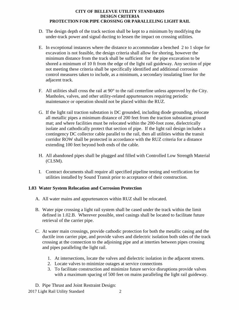
1.01 General
This section of the City of Bellevue (“City”) Utilities Department Engineering Standards
establishes the policies, procedures, and guidelines relating to utilities within the light rail
corridor. The criteria for protection of pipe in a shared utility corridor shall include
considerations for direct physical interferences, maintenance access encroachments, and stray
current corrosion control. Cathodic protection is required for metallic pipe and/or metallic
casings. Storm, Sewer, Water Pipes, and Manholes shall pass pressure and purity tests as
required in the City of Bellevue Utilities Department Engineering Standards. For non-metallic
pipe and/or casings see section 1.07 - Approved Non-Metallic Materials for Piping and Casings
for Water, Sewer, and Surface Water.
1.02 General Design Guidelines
A. Restricted Utility Zone (RUZ) defines the clearance for all utilities around a light rail as
follows:
1. Horizontally no less than 10- ft from the outside edge of the light rail guideway
unless otherwise approved by the City, without regard to depth and additional
length as required to accommodate a 2 to 1 slope excavation for pipe proximate to
ballasted track, a ballast wall or other retaining wall, or for deep excavations.
2. Vertically the top of utilities, encasements, sleeves, or casings crossing the rail shall
be a minimum of 1 ft vertical clearance from the power and signal ducting or other
structures and typically 6 ft below top of rail. Where a sewer or storm pipe is
crossing below the rail and the pipe needs to maintain a certain line or grade for
gravity flow, the vertical clearance may be reduced subject to the approval by the
City.
3. For elevated sections of track, horizontally at a minimum distance of 10 ft clearance
to columns and vertically wherever the overhead clearance is reduced to less than
14 ft.
B. All utilities within RUZ shall be relocated unless otherwise approved by the City. Pipe
outside this zone may remain in place unless affected by grade changes, limited access,
clearances or otherwise affected by light rail construction. Hence, all utilities
horizontally within the following limits shall be relocated.
1. 10-ft minimum from the outside edge of the light rail guideway; and
2. 10-ft minimum clearance to columns of elevated sections of track.
Replaced crossings shall be a minimum of 1-ft clearance from the power and signal
ducting. Where there is no alternative to reinstalling a parallel metallic pipe within the
RUZ, the pipe shall be cathodically protected and the adjacent track slab section shall
be constructed with a dielectric insulating liner.
C. Design considerations must anticipate construction sequencing and ongoing utility
service needs. Provide design to maintain critical services during construction.
CITY OF BELLEVUE UTILITY STANDARDS
DESIGN CRITERIA
PROTECTION FOR PIPE CROSSING OR PARALLELING LIGHT RAIL
2017 Light Rail Utility Standard 2
D. The design depth of the track section shall be kept to a minimum by modifying the
under-track power and signal ducting to lessen the impact on crossing utilities.
E. In exceptional instances where the distance to accommodate a benched 2 to 1 slope for
excavation is not feasible, the design criteria shall allow for shoring, however the
minimum distance from the track shall be sufficient for the pipe excavation to be
shored a minimum of 10 ft from the edge of the light rail guideway. Any section of pipe
not meeting these criteria shall be specifically identified and additional corrosion
control measures taken to include, as a minimum, a secondary insulating liner for the
adjacent track.
F. All utilities shall cross the rail at 90° to the rail centerline unless approved by the City.
Manholes, valves, and other utility-related appurtenances requiring periodic
maintenance or operation should not be placed within the RUZ.
G. If the light rail traction substation is DC grounded, including diode grounding, relocate
all metallic pipes a minimum distance of 200 feet from the traction substation ground
mat; and where facilities must be relocated within the 200-foot zone, dielectrically
isolate and cathodically protect that section of pipe. If the light rail design includes a
contingency DC collector cable parallel to the rail, then all utilities within the transit
corridor ROW shall be protected in accordance with the RUZ criteria for a distance
extending 100 feet beyond both ends of the cable.
H. All abandoned pipes shall be plugged and filled with Controlled Low Strength Material
(CLSM).
I. Contract documents shall require all specified pipeline testing and verification for
utilities installed by Sound Transit prior to acceptance of their construction.
1.03 Water System Relocation and Corrosion Protection
A. All water mains and appurtenances within RUZ shall be relocated.
B. Water pipe crossing a light rail system shall be cased under the track within the limit
defined in 1.02.B. Wherever possible, steel casings shall be located to facilitate future
retrieval of the carrier pipe.
C. At water main crossings, provide cathodic protection for both the metallic casing and the
ductile iron carrier pipe, and provide valves and dielectric isolation both sides of the track
crossing at the connection to the adjoining pipe and at interties between pipes crossing
and pipes paralleling the light rail.
1. At intersections, locate the valves and dielectric isolation in the adjacent streets.
2. Locate valves to minimize outages at service connections
3. To facilitate construction and minimize future service disruptions provide valves
with a maximum spacing of 500 feet on mains paralleling the light rail guideway.
D. Pipe Thrust and Joint Restraint Design:

CITY OF BELLEVUE UTILITY STANDARDS
DESIGN CRITERIA
PROTECTION FOR PIPE CROSSING OR PARALLELING LIGHT RAIL
2017 Light Rail Utility Standard 3
1. All carrier pipe joints in the casing shall be restrained. But this restrained length does
not contribute to restrained length design.
2. Restrain both sides of the valve to allow the pipe on either side of the valve to be
removed.
3. Restrain all fittings.
E. Steel casing pipe shall have welded joints, dielectric coating, and be protected with
galvanic anodes. Casing pipe installed in an open trench shall have tape wrap coating,
and casing pipe that is bored shall have fusion-bonded epoxy coating with field-coated
joints and all appurtenances shall be epoxy coated. Casing installations shall include
dielectric spacers, end seals, anodes, and test stations. Open trenching is the preferred
casing installation method. Where open trenching is not feasible, casing can be bored if it
is approved by the City. For bored installations, steel casing pipe may be uncoated
without anodes in lieu of coated steel pipe with anodes. Regardless of construction
methods used, the minimum wall thicknesses shall be based on American Railway
Engineering and Maintenance-of-Way Association (AREMA) design standards.
Casing Nominal Diameter
(inch)
Wall Thickness
(inch)
6 thru 14 0.25000
16 0.28125
18 0.31250
20 0.34375
22 0.34375
24 0.37500
26 0.40625
28 0.43750
30 0.46875
32 0.50000
34 0.53125
36 0.53125
F. Refer to Specification Section 264213 and Sheet 1 and Sheet 2 of the Cathodic Protection
Standard Details for the requirements of test stations and galvanic anodes.
G. Ductile iron mains inside the casing shall be of Class 56.
H. When grade and construction changes are needed along an existing cast iron water main,
the cast iron pipe strength and potential joint leakage due to excessive deflection from
added loadings (earth and live loads) shall be evaluated. Mitigation measures shall be
taken to resolve identified issues.
I. Casings shall be used for all pipe crossings except that solvent welded Schedule 80 PVC
sleeves may be used for water service pipes 2” and smaller. The sleeve inside diameter
shall be at least 2” larger than the service pipe outside diameter. Refer to Sheet 3 of the
Cathodic Protection Standard Details.

CITY OF BELLEVUE UTILITY STANDARDS
DESIGN CRITERIA
PROTECTION FOR PIPE CROSSING OR PARALLELING LIGHT RAIL
2017 Light Rail Utility Standard 4
J. Copper services crossing light rail track shall be of continuous tubing with no fittings and
shall be tape wrapped and sleeved under the track and for a minimum of 10 feet beyond
the edge of rail guideway (as referenced by face of curb outside of the rail slab). The
interstitial space between the tape wrapped copper service and the plastic pipe shall be
dry and sealed with a water tight connection.
K. All new ductile iron water mains within the street right-of-way and running parallel to the
light rail shall be made electrically continuous with joint bonds and shall be dielectrically
isolated into sections of 500 feet maximum length and at all connections. In addition, the
ductile iron mains shall be poly wrapped, and have anodes and test stations.
L. Cathodically protected pipe shall be dielectrically isolated from adjoining mains and
services. Provide ground rods on the customer side of meters that are isolated from the
service. Provide polarization cell replacements (PCRs) or other devices as required for
safety where there may be a touch or step potential between the local grounding and
remotely grounded pipe such as at hydrants and services near platforms or power traction
stations.
M. Additional fire hydrants shall be provided as necessary to allow for fire suppression
without requiring hoses to cross the tracks.
N. Construction, Maintenance and Repair Provisions – To accommodate construction and
future water system maintenance and repair, provide isolation valves for both sides of a
rail crossing and at maximum 500-ft lengths along water lines that parallel the light rail.
O. Test stations shall be provided at all dielectric isolation joints, casings, and at minimum
500-ft length intervals and as shown.
P. Pipes below the overhead tracks shall be treated the same as those for the tracks on grade
except the distance for clearance shall be based on the horizontal location of structural
column and vertically wherever overhead clearance is reduced to less than 14 feet.
1.04 Sanitary and Storm Sewer Relocation and Corrosion Protection
A. All sewers within the RUZ shall be relocated.
B. All sewer crossings shall be in casings unless where otherwise approved by the City of
Bellevue.
C. All new ductile iron sewer mains and metallic storm drain pipe within the street right-of-
way and running parallel to the light rail shall be made electrically continuous with joint
bonds and shall be dielectrically isolated into sections of 500 feet maximum length and at
all connections. In addition, the ductile iron and metallic mains or pipe shall be poly
wrapped, and have anodes and test stations.
D. For casings, refer to 1.03 above.
1.05 Criteria for Light Rail Track-to-Earth Resistance.

CITY OF BELLEVUE UTILITY STANDARDS
DESIGN CRITERIA
PROTECTION FOR PIPE CROSSING OR PARALLELING LIGHT RAIL
2017 Light Rail Utility Standard 5
A. Rail–to-Earth resistance shall be a minimum of 250 ohms/1,000-ft of four rail tie–and-
ballast track, 250 ohms /1,000 -ft of four rail direct fixation track, and 250 ohms/1,000- ft
of four rail embedded track.
B. The test method shall assure that no one short is greater than 20 ohms. Construction
methods shall include high voltage holiday tests; for sections of embedded rail holiday
testing shall be done prior to concrete placement and provide isolation testing between
rail and rebar immediately prior to placing concrete.
C. If the Rail-to-Earth Resistance criteria are not met, the transit authority will make all
reasonable efforts to determine the cause and correct the deficiency. If correction is not
feasible the transit authority will consult with the City to arrive at an acceptable remedy.
1.06 Criteria for Maintenance Agreement
A. The transit authority shall provide the following documentation to the City for approval:
1. A baseline report of stray current control including as a minimum Rail-to-Earth
Resistance, and if traction substations are DC grounded provide current
measurements, and if a proprietary stray current system is installed provide findings.
2. A light rail track cleaning program;
3. Immediate Rail- to-Earth Resistance testing of all repaired and replaced track;
4. A monitoring and maintenance program to assure continued Rail-to-Earth Resistance
and stray current control.
5. The City of Bellevue shall be notified if the Transit Authority elects to operate the
system DC (diode) grounded.
1.07 Approved Non-Metallic Materials for Piping and Casings for Water, Sewer, and
Surface Water.
The following materials are acceptable alternatives to metallic pipe for water, sewer, and surface
water mains (crossings and parallel mains) and steel casings to be used for rail crossings and
relocations within the Restricted Utility Zone (RUZ) of water, sewer, and surface water pipes.
The use of non-metallic piping for relocations and crossings, and for casings in lieu of metallic
pipe and steel casings (metallic pipe) will eliminate the requirement for furnishing and installing
exothermic welds between pipe joints, galvanic anodes, test stations, and other related materials
for cathodic protection.
A. Water main pipe: AWWA C-900, DR-18, gasketed joint (for pipe </= 12-inch diameter)
AWWA C-905, DR-18, gasketed joint (for pipe > 12-inch diameter)
B. Sewer main pipe: AWWA C900/C905 PVC Pipe: Gravity sewer pipe shall be
manufactured in accordance with AWWA Standard C900 or C905, with the following
additional requirements or exceptions:
AWWA PVC pipe shall be furnished in cast iron pipe equivalent outside diameters. For

CITY OF BELLEVUE UTILITY STANDARDS
DESIGN CRITERIA
PROTECTION FOR PIPE CROSSING OR PARALLELING LIGHT RAIL
2017 Light Rail Utility Standard 6
nominal diameters 4" through 12", refer to AWWA C900. For nominal diameters 14”
through 48”, refer to AWWA C905.
AWWA C900 and C905 PVC pipe up to 30” nominal diameter shall be DR 18.
Dimension Ratio (DR) for nominal diameters greater than 30” shall be as approved by the
City. Pipe joints shall be manufactured using an integral bell with an elastomeric gasket
push-on type joint. Elastomeric gaskets shall conform to ASTM F-477. All fittings shall
be PVC, compatible with pipe class called for in the plan, unless otherwise approved.
PVC fittings shall conform to AWWA C900 and C905 with respect to joint dimensions
and physical properties.
C. Storm Drain Pipe and Culvert Materials: Materials shall meet the noted sections of the
Standard Specifications and as modified herein:
AWWA PVC pipe shall be furnished in cast iron pipe equivalent outside diameters. For
nominal diameters 4" through 12", refer to AWWA C900. For nominal diameters 14”
through 48”, refer to AWWA C905.
AWWA C900 and C905 PVC pipe up to 30” nominal diameter shall be DR 18.
Dimension Ratio (DR) for nominal diameters greater than 30” shall be as approved by the
City. Pipe joints shall be manufactured using an integral bell with an elastomeric gasket
push-on type joint. Elastomeric gaskets shall conform to ASTM F-477. All fittings shall
be PVC, compatible with pipe class called for in the plan, unless otherwise approved.
PVC fittings shall conform to AWWA C900 and C905 with respect to joint dimensions
and physical properties.
Corrugated Polypropylene Pipe (Double and Triple Wall) shall meet ASTM F2736
requirements. Double wall corrugated polypropylene pipe is approved for use in culvert
and storm drainage applications in 12 to 30-inch diameters. Triple wall corrugated
polypropylene pipe is approved for use in culvert and storm drainage applications in 12 to
42-inch diameters.
D. Casings for Water, Sewer, and Surface Water Mains: AWWA C-905, DR-18, gasketed
joint (for casings up to 24-inch diameter).For casings over 24-inch in diameter, non-
metallic casings and materials may be approved on a case by case basis provided
engineering analysis shows it does not unduly deform under long term applied loadings
and has a predicted longevity in excess of 100 years. Controlled density fill should be
used to fully bed and encase non-metallic casings over 24-inch in diameter to prevent
long term deformation. Mortar end seals for casings 24-inch in diameter and over may be
approved on a case by case basis. Casing spacers per Utilities Department Engineering
Standards are required for all carrier pipes.
E. Pipe zone bedding and compaction for pipe and casings shall conform to Utilities
Department Engineering Standards for flexible pipe.

CITY OF BELLEVUE UTILITY STANDARDS
DESIGN CRITERIA
PROTECTION FOR PIPE CROSSING OR PARALLELING LIGHT RAIL
2017 Light Rail Utility Standard 7
SECTION 264213 – CORROSION CONTROL
PART 1 -- GENERAL
1.1 THE REQUIREMENT
A. The Contractor shall provide all equipment and materials required for a complete corrosion control system. Contract drawings indicate the extent and general arrangement of the system. The electrical isolation of the underground facilities, when not specified elsewhere, shall be included as a part of this Section of these specifications, and shall be accomplished in accordance with acceptable industry practice. The Contractor shall coordinate and properly relate his work to the site and to the work of all trades.
1.2 QUALITY CONTROL
A. All material and equipment shall be installed in accordance with the recommendations of the manufacturer as approved by the Owner’s Representative to conform to the Contract Documents. The installation, including testing, shall be performed by an organization that has not less than 5 years' experience in this type of work.
1.3 CONTRACTOR SUBMITTALS
A. Installation and Testing – Submit the name of the firm, the number of years of experience, and a list of not less than 5 installations that have been tested and found satisfactory in the last 5 years. Submit written documentation of experience as a professional engineer regularly performing cathodic protection work or certification as a NACE Cathodic Protection Specialist for all personnel performing field testing.
B. Shop Drawings – Provide submittals for all products referenced in this section, shown on the drawings, and those required for a complete system. Submittals shall include catalog number, cuts, and other descriptive data.
All shop drawings for the work covered in this Section shall be submitted at one time as a single submittal in order to demonstrate that the items have been properly coordinated and function properly as to the item's specific use, either by a particular type number reference on the drawings or in the specifications, or by a description of its specific location.
C. Test reports – Submit field test reports as specified in this section.
1.4 QUALITY CONTROL
A. All material and equipment shall be installed in accordance with the recommendations of the manufacturer as approved by the Owner’s Representative to conform to the Contract Documents. The installation, including testing, shall be performed by an organization that has not less than 3 years' experience in this type of work.
PART 2 -- PRODUCTS
2.1 EXOTHERMIC WELDS AND PIN BRAZING
A. Weld Materials - Molds, cartridges, and all required materials for exothermic (copper)
August 8, 2012 CORROSION CONTROL PAGE 264213 - 1

CITY OF BELLEVUE UTILITY STANDARDS
DESIGN CRITERIA
PROTECTION FOR PIPE CROSSING OR PARALLELING LIGHT RAIL
2017 Light Rail Utility Standard 8
welding shall be as produced by “Cadweld”, Erico Products, Inc., or approved equal. Provide molds and cartridges of a size and material as recommended in writing by the manufacturer. Molds for exothermic welding shall be graphite; ceramic molds are not acceptable.
1. Ductile Iron Pipe - For connection to ductile iron pipe, use “Cadweld” XF-19 alloy weld metal or approved equal.
2. Cast Iron Pipe - For connection to cast iron pipe, use “Cadweld” XF-19 alloy weld metal or approved equal.
3. Steel Pipe - For connection to steel pipe, use "Cadweld" F-33 alloy weld metal alloy or approved equal.
B. Terminals - All wires used with exothermic welds shall have formed sleeve terminals and shall be welded using the reduced weld size and special weld mold for formed terminals, as specified in writing by the manufacturer. The formed terminals may be factory fabricated or may be field formed using sleeves and a hammer die. Connections to mortar coated steel or concrete cylinder pipe shall be exothermically welded to a 1/2 inch diameter steel rod preinstalled on the pipe by the pipe manufacturer.
C. Pin Brazing - Pins, studs, lugs and ferrules shall be as recommended in writing by the manufacturer for the wire size, pipe material, and pin braze machine settings.
D. Weld Caps - Furnish weld caps of high-density plastic, 10 mils (minimum) thickness Handy Cap IP, as manufactured by Royston Laboratories, or approved equal. Provide caps that incorporate a dome for the weld, a tunnel to contain the lead wire from the weld connection, and a base plate to cover the prepared pipe surface. Weld caps shall be provided pre-filled with mastic/adhesive and have an integral primer for adhesion to the pipe or structure. Weld caps shall be sized for the exothermic or pin brazed connection.
2.2 GALVANIC ANODES
A. Supply galvanic anodes of the quantity, composition, dimensions, metal weight, and packaged backfill as shown or noted on the drawings. Provide magnesium anodes, nominal 20 inches long and nominal 30 pound bare metal weight. Magnesium anodes shall meet the requirements of ASTM B-843-M1C High Potential Magnesium Alloy and ASTM G97 with an open circuit potential of (-)1.7VDC to CSE and a current efficiency of 50%. The anodes shall be prepackaged in a permeable cloth bag containing the manufacturer’s prescribed backfill and the packaged anode shall be nominal 2.5 times the bare anode weight. The anode lead wire shall be solid copper wire, AWG #12 or #10, with TW-, THHN-, or USE-type insulation, and the connection to the anode shall be silver soldered by the manufacturer and shall be of an un-spliced length specific to the application but not less than 15 feet.
2.3 TEST STATIONS AND COUPONS
A. Test stations – Flush-mounted test stations shall be as shown on the drawings with City’s standard CIV boxes and covers.
B. Cathodic Protection Monitoring Coupons – Provide coupons, steel or ductile iron, to match the pipe material type. The coupon shall have 2 wires connected with a silver
August 8, 2012 CORROSION CONTROL PAGE 264213 - 2
CITY OF BELLEVUE UTILITY STANDARDS
DESIGN CRITERIA
PROTECTION FOR PIPE CROSSING OR PARALLELING LIGHT RAIL
2017 Light Rail Utility Standard 9
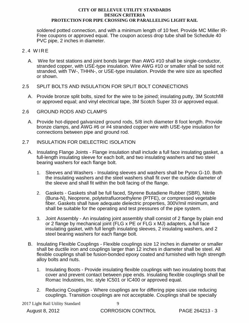
soldered potted connection, and with a minimum length of 10 feet. Provide MC Miller IR-Free coupons or approved equal. The coupon access drop tube shall be Schedule 40 PVC pipe, 2 inches in diameter.
2 . 4 W I R E
A. Wire for test stations and joint bonds larger than AWG #10 shall be single-conductor, stranded copper, with USE-type insulation. Wire AWG #10 or smaller shall be solid not stranded, with TW-, THHN-, or USE-type insulation. Provide the wire size as specified or shown.
2.5 SPLIT BOLTS AND INSULATION FOR SPLIT BOLT CONNECTIONS
A. Provide bronze split bolts, sized for the wire to be joined; insulating putty, 3M Scotchfill or approved equal; and vinyl electrical tape, 3M Scotch Super 33 or approved equal.
2.6 GROUND RODS AND CLAMPS
A. Provide hot-dipped galvanized ground rods, 5/8 inch diameter 8 foot length. Provide bronze clamps, and AWG #6 or #4 stranded copper wire with USE-type insulation for connections between pipe and ground rod.
2.7 INSULATION FOR DIELECTRIC ISOLATION
A. Insulating Flange Joints - Flange insulation shall include a full face insulating gasket, a full-length insulating sleeve for each bolt, and two insulating washers and two steel bearing washers for each flange bolt.
1. Sleeves and Washers - Insulating sleeves and washers shall be Pyrox G-10. Both the insulating washers and the steel washers shall fit over the outside diameter of the sleeve and shall fit within the bolt facing of the flange.
2. Gaskets - Gaskets shall be full faced, Styrene Butadiene Rubber (SBR), Nitrile (Buna-N), Neoprene, polytetrafluoroethylene (PTFE), or compressed vegetable fiber. Gaskets shall have adequate dielectric properties, 300V/mil minimum, and shall be suitable for the operating and test pressures of the pipe system.
3. Joint Assembly - An insulating joint assembly shall consist of 2 flange by plain end or 2 flange by mechanical joint (FLG x PE or FLG x MJ) adapters, a full face insulating gasket, with full length insulating sleeves, 2 insulating washers, and 2 steel bearing washers for each flange bolt.
B. Insulating Flexible Couplings - Flexible couplings size 12 inches in diameter or smaller shall be ductile iron and couplings larger than 12 inches in diameter shall be steel. All flexible couplings shall be fusion-bonded epoxy coated and furnished with high strength alloy bolts and nuts.
1. Insulating Boots - Provide insulating flexible couplings with two insulating boots that cover and prevent contact between pipe ends. Insulating flexible couplings shall be Romac Industries, Inc. style IC501 or IC400 or approved equal.
2. Reducing Couplings - Where couplings are for differing pipe sizes use reducing couplings. Transition couplings are not acceptable. Couplings shall be specially
August 8, 2012 CORROSION CONTROL PAGE 264213 - 3

CITY OF BELLEVUE UTILITY STANDARDS
DESIGN CRITERIA
PROTECTION FOR PIPE CROSSING OR PARALLELING LIGHT RAIL
2017 Light Rail Utility Standard 10
ordered and sized for an insulating boot on one side and thrust restraint on the other side.
C. Insulating Copper Service Fittings - Fittings shall have insulators integral to the body of the fitting, as manufactured by Meuller Company or approved equal. The design of the fitting shall include a mechanical restriction to prevent the copper tube from passing through the insulation.
D. Insulating Wall Seals - Wall seals shall consist of compression disks and pressure plates made of dielectric materials. Insulating wall seals shall be Model C Insulating Type as manufactured by Link Seal or approved equal.
2.8 CASINGS AND SLEEVES
A. Casing Spacers and Casing End Seals - Casing spacers shall be constructed with fusion-bonded epoxy coated steel bands and reinforced insulating runners. If stainless steel bands are approved by the Owner, the bands shall be separated from the pipe with a manufacturer’s elastomeric boot. Casing end seals shall be pull-on style with stainless steel clamps, custom sized for the OD of the casing and carrier pipe. Provide end seals, Type C, as manufactured by PSI or approved equal. Polyethylene encasement shall extend through the end seal and casing.
B. Sleeve Slip-on and End Seals - Sleeves shall be ASTM D1785 Schedule 80 PVC pipe, 4 inch minimum pipe diameter.
1. Sleeve End Seals for DI Pipe- End seals for sleeved pipe shall be concentric elastomeric couplings PVC to DI with stainless steel clamps as manufactured by FERNCO, Inc. or approved equal. Couplings shall be sized to specific pipe type and size.
2. Sleeve End Seals for Copper Service - End seals for sleeved copper services shall be pull on elastomeric molded pipe sleeve seals with stainless steel clamps. Provide pipe sleeves by Fernco, Inc. or approved equal. Step down from 4 inch to the required copper tube size with schedule 80 PVC reducers. Molded end seals shall be sized specific to the pipe type and size.
3. Sleeve Wrapped - Furnish 40 mil PVC reinforced geo-membrane with 300V/mil dielectric strength and minimum 150 pound puncture resistance and 150 pound tensile strength.
2.9 POLYETHYLENE ENCASEMENT AND TAPE WRAP:
A. Polyethylene Encasement for DI Pipe - Furnish 8 mil Type 2 high density cross laminated polyethylene film in accordance with AWWA C105 tube type encasement. Polyethylene sheet is not acceptable. Furnish polyethylene encasement from the same manufacturer that supplies the ductile iron pipe.
B. Tape Wrap Coating for Casing - Provide tape wrap coating for casing pipes in accordance with AWWA C203, AWWA C209, AWWA C214, or AWWA C216. Provide tape system per manufacturer’s requirements for repair and to cover holdbacks.
C. Tape Wrap for Copper Tube - Provide a 20 mil minimum PVC tape wrap coating for copper services and insulating joints. Provide Scotchwrap 51 or approved equal.
August 8, 2012 CORROSION CONTROL PAGE 264213 - 4

CITY OF BELLEVUE UTILITY STANDARDS
DESIGN CRITERIA
PROTECTION FOR PIPE CROSSING OR PARALLELING LIGHT RAIL
2017 Light Rail Utility Standard 11
D. Tape Wrap Coating for Specials - When specified provide petrolatum wax tape system per AWWA C217 with an auxiliary thin film conforming stretch outlet wrap.
2.10 THIN FILM COATINGS
A. Epoxy Coating for Buried Casing, and Epoxy Coating for Mortar Coated Steel Pipe (MCSP) and Concrete Cylinder Pipe (CCP) - for casing pipe provide coating materials per AWWA C210, AWWA C213, except no coal tar epoxy will be allowed. For MCSP and for CCP the coating shall be applied by the manufacturer at the manufacturing plant and shall be the standard dielectric epoxy provided by the manufacturer for pipe in stray current and corrosive environments per AWWA M-9.
B. Epoxy Repair - Provide 100% solids 2 component quick cure epoxy coating, NSF approved for potable water. Provide 3M Scotchkote 323 brush grade or approved equal.
C. Epoxy Coatings for Pipe on Bridges - Provide epoxy primer and intermediate coats with an aliphatic polyurethane topcoat. Provide Pota-Pox epoxy primer and intermediate coats and an Endura-Shield polyurethane topcoat all by Tnemec or approved equal.
D. Moisture Cured Urethane Coating for Pipe on Bridges - Provide a zinc and micaceous iron oxide moisture-cured urethane system. Provide an MC-Miozinc primer, an MC Miomastic intermediate coat, and a Ferrox A topcoat all by Wasser High Tech Coatings or approved equal.
E. Thixotropic Mastic Coating - Provide a thixotropic mastic coating for field repair of existing coal-tar enamel that is not in contact with potable water. Provide Carboline Bitumastic 50 or approved equal.
F. Leafing Aluminum Epoxy Coating - Provide a leafing aluminum epoxy mastic for marginally prepared surfaces. Provide Carbomastic 15 LO by Carboline or approved equal.
G. Galvanizing - Galvanized items shall be per ASTM A123 & ASTM A153. Provide zinc base alloys for repair per ASTM A780. Hot stick method, zinc-rich paints are not acceptable.
H. Silicate Concrete Coating - Provide a water based silicate sealer for waterproofing the exterior surface of new concrete vaults.
2.11 MORTAR, GROUT, GROUT BAND
A. Mortar and grout shall be a chloride free Portland cement and sand mix with not less than 1 part cement to 3 parts sand or a proprietary cementitious chloride free mix approved in writing by the pipe manufacturer. The grout band shall physically contain the mortar/ grout and prevent moisture loss.
2.12 BACKFILL
A. Backfill in the pipe zone shall be aggregate or sand. Controlled density fill (CDF) and
August 8, 2012 CORROSION CONTROL PAGE 264213 - 5
CITY OF BELLEVUE UTILITY STANDARDS
DESIGN CRITERIA
PROTECTION FOR PIPE CROSSING OR PARALLELING LIGHT RAIL
2017 Light Rail Utility Standard 12
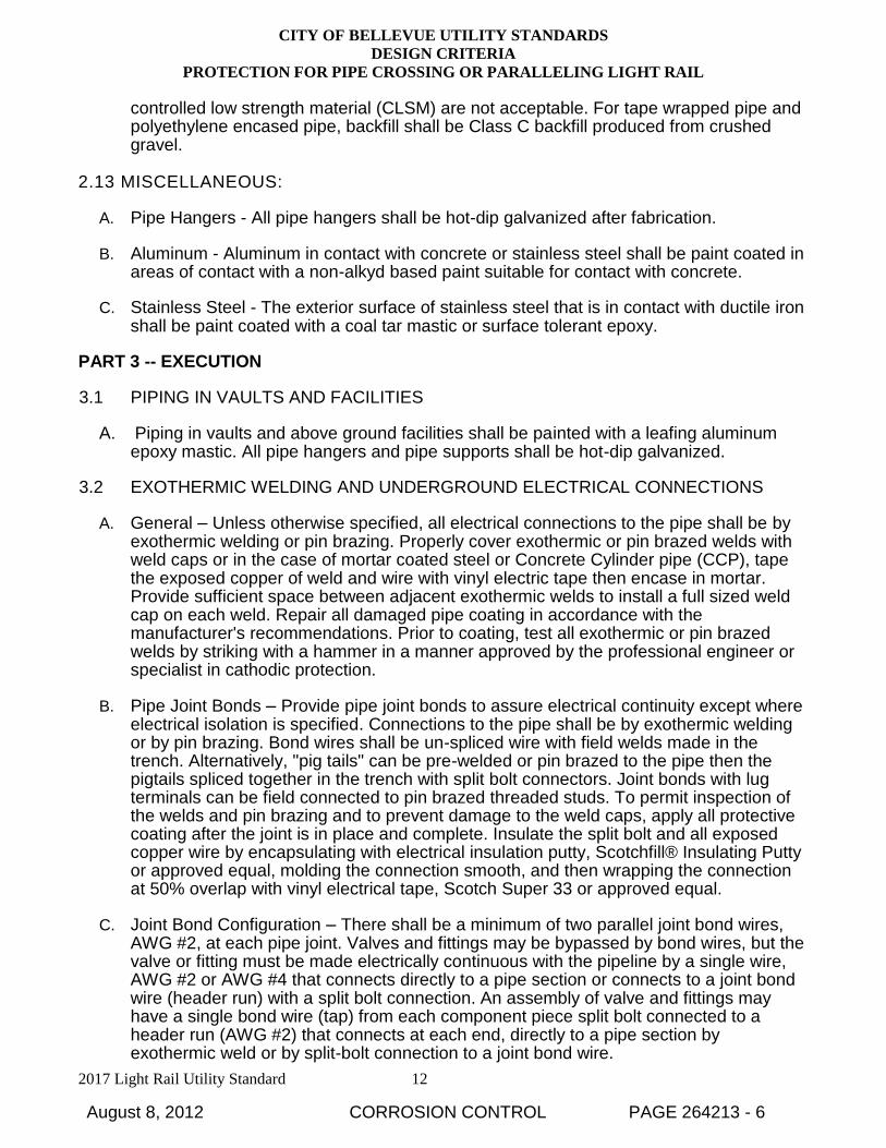
controlled low strength material (CLSM) are not acceptable. For tape wrapped pipe and polyethylene encased pipe, backfill shall be Class C backfill produced from crushed gravel.
2.13 MISCELLANEOUS:
A. Pipe Hangers - All pipe hangers shall be hot-dip galvanized after fabrication.
B. Aluminum - Aluminum in contact with concrete or stainless steel shall be paint coated in areas of contact with a non-alkyd based paint suitable for contact with concrete.
C. Stainless Steel - The exterior surface of stainless steel that is in contact with ductile iron shall be paint coated with a coal tar mastic or surface tolerant epoxy.
PART 3 -- EXECUTION
3.1 PIPING IN VAULTS AND FACILITIES
A. Piping in vaults and above ground facilities shall be painted with a leafing aluminum epoxy mastic. All pipe hangers and pipe supports shall be hot-dip galvanized.
3.2 EXOTHERMIC WELDING AND UNDERGROUND ELECTRICAL CONNECTIONS
A. General – Unless otherwise specified, all electrical connections to the pipe shall be by exothermic welding or pin brazing. Properly cover exothermic or pin brazed welds with weld caps or in the case of mortar coated steel or Concrete Cylinder pipe (CCP), tape the exposed copper of weld and wire with vinyl electric tape then encase in mortar. Provide sufficient space between adjacent exothermic welds to install a full sized weld cap on each weld. Repair all damaged pipe coating in accordance with the manufacturer's recommendations. Prior to coating, test all exothermic or pin brazed welds by striking with a hammer in a manner approved by the professional engineer or specialist in cathodic protection.
B. Pipe Joint Bonds – Provide pipe joint bonds to assure electrical continuity except where electrical isolation is specified. Connections to the pipe shall be by exothermic welding or by pin brazing. Bond wires shall be un-spliced wire with field welds made in the trench. Alternatively, "pig tails" can be pre-welded or pin brazed to the pipe then the pigtails spliced together in the trench with split bolt connectors. Joint bonds with lug terminals can be field connected to pin brazed threaded studs. To permit inspection of the welds and pin brazing and to prevent damage to the weld caps, apply all protective coating after the joint is in place and complete. Insulate the split bolt and all exposed copper wire by encapsulating with electrical insulation putty, Scotchfill® Insulating Putty or approved equal, molding the connection smooth, and then wrapping the connection at 50% overlap with vinyl electrical tape, Scotch Super 33 or approved equal.
C. Joint Bond Configuration – There shall be a minimum of two parallel joint bond wires, AWG #2, at each pipe joint. Valves and fittings may be bypassed by bond wires, but the valve or fitting must be made electrically continuous with the pipeline by a single wire, AWG #2 or AWG #4 that connects directly to a pipe section or connects to a joint bond wire (header run) with a split bolt connection. An assembly of valve and fittings may have a single bond wire (tap) from each component piece split bolt connected to a header run (AWG #2) that connects at each end, directly to a pipe section by exothermic weld or by split-bolt connection to a joint bond wire.
August 8, 2012 CORROSION CONTROL PAGE 264213 - 6
CITY OF BELLEVUE UTILITY STANDARDS
DESIGN CRITERIA
PROTECTION FOR PIPE CROSSING OR PARALLELING LIGHT RAIL
2017 Light Rail Utility Standard 13
D. Wiring – All wiring is to be splice-free, except where splices are specified or shown or as approved. Coil or snake all buried wire with sufficient slack to prevent stress from backfill operations and earth settlement. All wire is to be buried a minimum of 30 inches above finish grade or installed in rigid conduit. All wire at test stations shall extend a minimum of 30 inches below finished grade or shall be installed in rigid conduit. Repair any damage to the wire insulation with self-adhering butyl rubber electrical tape, Scotch No. 130C or approved equal, and over wrap with vinyl electrical tape, Scotch No. 33 or approved equal. Spirally apply each layer at 50% overlap. This repair method is not applicable to repair of any wire in an impressed current system.
E. Split Bolt Connections – Split bolt connections shall be limited to the connection of two wires. Three or more wires at one split bolt are not allowed. Connection of taps to header runs may be accomplished by stripping an appropriate length of insulation from the header without cutting the wire and connecting the tap at that point with a split bolt for each tap.
3.3 GROUND RODS
A. If the service is dielectrically isolated from the main, provide a ground rod, installed per National Electric Code, and connected to the customer side of the service.
3.4 GALVANIC ANODE INSTALLATION
A. General – Unless specified otherwise, install anodes 5 feet below the pipe invert, positioned under the pipe or up to 3 feet perpendicular from the pipe edge. Do not place the anodes within 3 feet of a neighboring metallic structure. When anodes are distributed along the pipeline, alternate the perpendicular offset from one side of the pipe to the other.
B. Location – Install the anode in clean, native backfill and not in the select bedding material. Locate anodes a minimum of 5 ft apart. Thoroughly soak the anode in water prior to installation. Compact the backfill to 95% of maximum density to 1 foot above the anode. Evenly distribute anodes along main and branch line installations. Anodes may be grouped at the ends of casings and short runs of pipe; maintain 5 ft minimum distance between anodes.
C. Connection – The anode lead wire shall be exothermically welded to the pipe. Alternatively the anode shall be connected to a joint bonding wire by using a split-bolt connection. Distances between anodes are nominal lengths and anode connections shall be made at pipe joints. Unless otherwise specified, for ductile iron water mains and steel pipe and casings, provide anodes as shown.
3.5 TEST STATION INSTALLATION - LOCATE TEST STATIONS AS FOLLOWS:
A. Isolation Joint Test Stations (TSIJ) - Provide a test station at all buried insulated flanges and insulating couplings, except insulated connections on copper services. Provide a test station at the dielectric isolation between mortar coated steel or CCP lines and dielectrically isolated branch lines, unless the Engineer elects to not install test stations at these locations. Insulating Joint Test stations shall have (2) AWG #8 wires welded to each side of the dielectric joint, 4 wires total.
August 8, 2012 CORROSION CONTROL PAGE 264213 - 7
CITY OF BELLEVUE UTILITY STANDARDS
DESIGN CRITERIA
PROTECTION FOR PIPE CROSSING OR PARALLELING LIGHT RAIL
2017 Light Rail Utility Standard 14
B. Casing Test Stations (TSC) - Provide one test station at each end of the casing. Casing Test Stations shall have (2) AWG #8 wires welded to the main and (2) AWG #8 wires welded to the casing, 4 wires total.
C. Monitoring Test Stations (TSM) - Provide a monitoring test station with cathodic protection monitoring coupons where water mains cross cathodically protected foreign lines and where water mains cross electric rail tracks. Monitoring Test Stations shall have (2) AWG #8 wires welded to the main, and (2) cathodic protection monitoring coupons, each with (2) AWG #12 wires, 6 wires total.
D. Combination Test Stations (TSC/IJ) - When two or more test stations on the same pipe are adjacent to each other (within 15 feet) they may be combined and the test wires run to a single flush mounted test station. A TSIJ near the end of a casing may be combined with the TSC into a single test station with two AWG #8 wires to the casing, two AWG #8 wires to the casing side of the dielectric joint and two AWG #8 wires to the far side of the dielectric joint, 6 wires total. A TSM can be included in the combined test station by providing (2) cathodic protection monitoring coupons without additional wires to the pipe or casing.
3.6 DIELECTRIC ISOLATION:
A. General – Provide pipe isolation with insulating flange joints, or insulating flexible couplings. Insulating joints shall be separate assemblies and not incorporated into joints with valves or other appurtenances with the exception of branch lines connected to Mortar Coated Steel Pipe (MCSP) or Concrete Cylinder Pipe. Where a branch line connects to a flange integral with a section of MCSP or CCP, a separate assembly is not required. Copper services shall be isolated with meter stops designed with integral insulation. Use insulating wall seals at all concrete wall penetrations.
B. Insulating joints – Mechanical joint assemblies of flange coupling adapters may be assembled above grade complete with attached test wires. Tape the flange edge of insulating joints with PVC tape to prevent particle bridging across the flange faces. Insulating flexible couplings shall have an insulating boot on each pipe end. Reducing insulating flexible couplings shall have a boot on one pipe end and restraining bolts on the other. Transition couplings are not acceptable. Use reducing couplings to accommodate differing pipe size. Joint restraint at flexible couplings shall only use hot-dip galvanized rod and nuts and shall be insulated from the non-cathodically protected side of a joint, or insulated from the mortar coated side of a joint, or insulated on one side of the joint if both sides are cathodically protected.
3.7 POLYETHYLENE ENCASEMENT SLEEVE WRAPPED AND TAPE WRAPPED:
A. Polyethylene Encasement Installation - Install polyethylene encasement, tube type, on all ductile iron pipe and appurtenances. Install one length of polyethylene tube encasement for each length of pipe in accordance with AWWA C105, Method A. Every 6 feet along the pipe, secure the polyethylene tube encasement with tape full circumference. The use of polyethylene sheets will not be allowed. Install 40 mil geo-membrane around mechanical joints and similar connections where the polyethylene can be punctured or ripped. Tape the ends and seams of the geo-membrane with tape and then cover the pipe joint with the adjoining polyethylene encasement. Bedding and backfill around polyethylene or geo-membrane encased pipe shall be Class C backfill produced from crushed gravel.
August 8, 2012 CORROSION CONTROL PAGE 264213 - 8
CITY OF BELLEVUE UTILITY STANDARDS
DESIGN CRITERIA
PROTECTION FOR PIPE CROSSING OR PARALLELING LIGHT RAIL
2017 Light Rail Utility Standard 15
B. Sleeve Wrapped Installation – Install geo-membrane when crossing a cathodically protected foreign line where the pipe configuration does not allow for a PVC pipe sleeve.
C. Tape Wrapped Coating for Casings - Apply tape wrapped coating on steel casing pipe in accordance with AWWA C203, AWWA C214, AWWA C216 for manufacturer applied tape wrap and AWWA C209 for minor field applications. For tape wrapped coating repairs and other coating holdback areas, apply repair tape system per manufacturer’s requirements. Apply petrolatum wax tape per AWWA C217 with outer wrap only where directed.
D. Tape Wrapped Coating for Copper Services – Provide 20 mil PVC tape wrap and apply at 50% overlap, 40 mil total. Wrap the copper tube, and all fittings including corporation and meter stop.
E. Mortar Coated Steel (MCSP) and Concrete Cylinder Pipe (CCP) – Transmission mains shall have continuous mortar coating over all in-line valves, fittings, and other appurtenances, regardless of underlying coating, except where allows the application of a dielectric coating and installation of anodes at a valve, fitting or other appurtenance is allowed in lieu of mortar coating.
3.8 THIN FILM COATINGS
A. Paint for Buried Casings, Casing Welds – Provide an epoxy coating per AWWA C210 and AWWA C213. Any angle iron, c-channels, lubricating or grout pipe, fins, or other appurtenances connected to the casing shall be epoxy coated on all sides. For field repairs, prepare the surface by power tool cleaning, SSPC-SP3, and repair with a 100% solids epoxy, one coat of 25 mil dry film thickness (mdft), or as when permitted, coat the weld with a thixotropic coal tar mastic, one coat of 20 mdft.
B. Paint Coating for Pipe in Vaults and Facilities – Coat all piping except fittings and specials that are factory coated with fusion-bonded epoxy. Prepare the surface by power tool cleaning, SSPC-SP3, or shop abrasive brush blasting, SSPC-SP7. Use a needle gun or abrasive blast to disrupt the asphaltic coating on ductile iron pipe and fittings, but it is not necessary to remove all asphaltic coating. All work in vaults and facilities shall be done with HEPA filter equipment. Do not coat bolt areas such as flanges or restrained joint holdback areas until connection is complete. Coat with a leafing aluminum epoxy mastic, Carboline Carbomastic 15 or approved equal, 2 coats minimum with 6 mdft per coat, 12 mdft total.
Steel pipe, fittings and specials, 16” diameter and larger, shall be shop coated, except for hold backs, prior to installation. Surface preparation shall be near white abrasive blast SSPC-SP10 and the coating shall be a leafing aluminum epoxy mastic, 2 coats 6 mdft per coat, 12 mdft total.
C. Paint Coating for Pipe on Bridges – Shop blast and shop coat pipe except for hold back areas. Surface preparation and application of coatings shall be in accordance with manufacturer’s written recommendations
1. Ductile Iron (DI) Pipe – For ductile iron pipe prepare the surface by power tool cleaning, SSPC-SP3, or shop abrasive brush blasting, SSPC- SP7. Use a needle gun or abrasive blast to disrupt the asphaltic coating on DI pipe and fittings, but it is not necessary to remove all asphaltic coating. Do not coat bolt areas such as
August 8, 2012 CORROSION CONTROL PAGE 264213 - 9

CITY OF BELLEVUE UTILITY STANDARDS
DESIGN CRITERIA
PROTECTION FOR PIPE CROSSING OR PARALLELING LIGHT RAIL
2017 Light Rail Utility Standard 16
flanges or restrained joint holdback areas until connection is complete. Coat with a leafing aluminum epoxy mastic, Carboline Carbomastic 15 or approved equal, 2 coat minimum with 6 mdft per coat, 12 mdft total.
2. Steel Pipe – For steel pipe prepare the surface by near white abrasive blasting SSPC-SP10. Coat with:
a. leafing aluminum epoxy mastic, 6 mdft per coat 12 mdft total, or
b. an epoxy coating system, 3 coats of 3-4 mdft per coat, 9-12 mdft total, or
c. a moisture-cured urethane system at 3 mdft prime coat, 3 mdft intermediate coat, and 2 mdft topcoat, 8 mdft total. d. Galvanizing - Repair of galvanizing shall be per ASTM A780 using the zinc based alloys “hot stick” method. Zinc-rich paint is not permitted.
3.9 TESTING AND VERIFICATION
A. Quality Assurance – The portion of the work that involves the installation and testing of galvanic cathodic protection, joint bonding, test stations, dielectric isolation, or coatings shall be conducted by a professional engineer regularly performing cathodic protection work or by an individual who is registered or certified by the National Association of Corrosion Engineers (NACE) as a cathodic protection specialist. Submit verification of registration or certification for written approval prior to the start of the work.
B. Field Verifications – The professional engineer or specialist in cathodic protection shall field verify the adequacy of the Contractor's personnel in handling and placing anodes, monitoring coupons, exothermic welding, installation of split bolt connectors, repair of coatings including weld caps, and measurements of dielectric isolation and bonding. The professional engineer or specialist in cathodic protection shall at the start of the work provide a list of qualified Contractor personnel and only these listed individuals shall perform such work for the Contractor.
C. Testing During Construction – Test all isolation joints after installation and prior to backfilling.
D. Continuity and Isolation Testing – Perform testing as follows:
1. General - Test all sections of pipeline, appurtenances, services, hydrants, regulator vaults, and appurtenances that are cathodically protected and dielectrically isolated for electrical continuity and dielectric isolation after all Contractor connections have been made.
2. Test Current Response - Measure the response of the pipe to the application of cathodic protection test current. If the application of the test current causes the pipe-to-soil potential to become more negative, electrical continuity of the pipeline, service runs, and appurtenances is indicated between that point and the point at which the test rectifier negative connection was made. The response of the potential shall be of a magnitude to demonstrate low resistance joint bonds. Electrical isolation across insulating fittings shall be indicated by the pipe-to-soil potential being more positive or only slightly negative in relation to the structure connected to the test rectifier.
August 8, 2012 CORROSION CONTROL PAGE 264213 - 10

CITY OF BELLEVUE UTILITY STANDARDS
DESIGN CRITERIA
PROTECTION FOR PIPE CROSSING OR PARALLELING LIGHT RAIL
2017 Light Rail Utility Standard 17
E. Lack of Continuity or Isolation – If electrical continuity or electrical isolation is not achieved, locate the deficiency and complete the necessary repairs. The engineer or specialist shall retest the system before final acceptance.
F. Repairs - Make all repairs necessary to correct any deficiencies and repair any joint not passing the electrical continuity or isolation test at no cost to the City.
G. Final System Testing – Final system testing shall be performed prior to the hydrostatic testing of each segment and prior to the substantial completion. Final testing shall be performed directly by the professional engineer or specialist in cathodic protection and witnessed by the City and shall include the following as a minimum stations and for all service connections.
1. Test and Service Locations – Provide pipe-to-soil potential measurements for all test stations and for all service connections.
2. Continuity and Isolation Measurements – Provide a report consisting of continuity and isolation measurements and other data for all cathodically protected sections of pipe, appurtenances, and for all service connections.
3. Documentation – Provide 3 copies of a report documenting all testing and installation of cathodic protection system. The professional engineer shall stamp or the cathodic protection specialist shall sign the report. Include the specialist’s NACE registration or certification number.
August 8, 2012 CORROSION CONTROL PAGE 264213 - 11
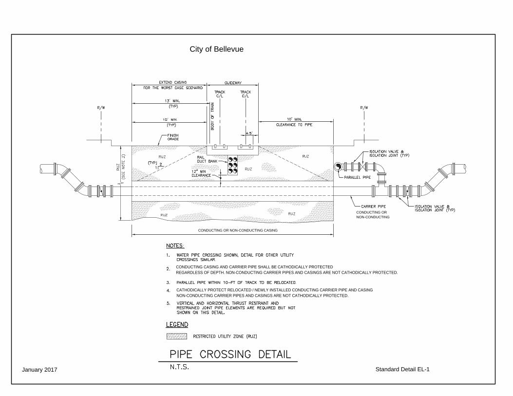
January 2017
City of Bellevue
Standard Detail EL-1
CONDUCTING CASING AND CARRIER PIPE SHALL BE CATHODICALLY PROTECTEDREGARDLESS OF DEPTH. NON-CONDUCTING CARRIER PIPES AND CASINGS ARE NOT CATHODICALLY PROTECTED.
CONDUCTING OR NON-CONDUCTING CASING
CATHODICALLY PROTECT RELOCATED / NEWLY INSTALLED CONDUCTING CARRIER PIPE AND CASING NON-CONDUCTING CARRIER PIPES AND CASINGS ARE NOT CATHODICALLY PROTECTED.
CONDUCTING OR NON-CONDUCTING

January 2017
EL-2CATHODIC PROTECTION SHEET 1 of 3

January 2017
CATHODIC PROTECTION SHEET 2 of 3EL-3

January 2017
EL-4CATHODIC PROTECTION SHEET 3 of 3