City of Bellevue Development Services Department Land Use ...

CITY OF BELLEVUE
UTILITIES DEPARTMENT
SANITARY SEWER ENGINEERING STANDARDS
JANUARY 2017
www.bellevuewa.gov/utilities_codes_standards_intro.htm

SANITARY SEWER ENGINEERING STANDARDS JANUARY 2017
SANITARY SEWER ENGINEERING STANDARDS
TABLE OF CONTENTS
CHAPTER S1 – GENERAL REQUIREMENTS
S1-01 GENERAL ............................................................................................. S1 - 1
S1-02 DEFINITIONS ....................................................................................... S1 - 1
S1-03 REFERENCES ...................................................................................... S1 - 3
S1-04 GOVERNMENTAL AGENCY REQUIREMENTS ............................. S1 - 4
CHAPTER S2 – PLAN SUBMITTAL
S2-01 GENERAL ............................................................................................. S2 - 1
S2-02 DEVIATIONS ....................................................................................... S2 - 1
S2-03 ERRORS AND OMISSIONS ................................................................ S2 - 1
S2-04 PLANS ................................................................................................... S2 - 1
S2-05 AS-BUILT DOCUMENTATION ......................................................... S2 - 7
CHAPTER S3 – SEWER PLANNING/DESIGN STANDARDS
S3-01 PLANNING CRITERIA ........................................................................ S3 - 1
S3-02 GENERAL DESIGN STANDARDS .................................................... S3 - 2
S3-03 MAIN LINES......................................................................................... S3 - 3
S3-04 MANHOLES ......................................................................................... S3 - 4
S3-05 PIPE CLASS – PROTECTION – COVER ........................................... S3 - 7
S3-06 CLEARANCES – OTHER UTILITIES ................................................ S3 - 8
S3-07 CONNECTIONS TO EXISTING SYSTEM ......................................... S3 – 9
S3-08 FATS, OILS, GREASE SEPARATION ............................................. S3 – 10
S3-09 EASEMENTS ...................................................................................... S3 - 12
SANITARY SEWER ENGINEERING STANDARDS JANUARY 2017
S3-10 SIDE SEWERS .................................................................................... S3 - 14
CHAPTER S4 – SEWER MATERIALS
S4-01 GENERAL ............................................................................................. S4 - 1
S4-02 GRAVITY SEWER PIPE & FITTINGS ............................................... S4 - 1
S4-03 PRESSURE SEWER PIPE .................................................................... S4 - 2
S4-04 HDPE PIPE ............................................................................................ S4 - 3
S4-05 ABS PIPE & FITTINGS ........................................................................ S4 - 3
S4-06 FITTINGS .............................................................................................. S4 - 3
S4-07 CAPS AND PLUGS .............................................................................. S4 - 3
S4-08 BOLTS IN PIPING ................................................................................ S4 - 3
S4-09 FLANGE GASKETS ............................................................................. S4 - 4
S4-10 GATE VALVE ...................................................................................... S4 - 4
S4-11 VALVE BOX......................................................................................... S4 - 4
S4-12 VALVE OPERATING NUT EXTENSION .......................................... S4 - 4
S4-13 MANHOLES ......................................................................................... S4 - 4
S4-14 MANHOLE LINING ............................................................................. S4 – 5
S4-15 MANHOLE RING & COVER .............................................................. S4 - 5
S4-16 CONCRETE BEDDING & BLOCKING .............................................. S4 - 6
S4-17 OIL/WATER SEPARATOR ................................................................. S4 - 6
S4-18 GREASE INTERCEPTOR .................................................................... S4 – 6
S4-19 LIDS, HATCHES AND COVERS – SLIP RESISTANCE .................. S4 - 7
S4-20 COMMERCIAL CLEAN-OUT WITH TEST SAMPLING TEE ......... S4 - 7
S4-21 BACKWATER VALVE ........................................................................ S4 - 7

SANITARY SEWER ENGINEERING STANDARDS JANUARY 2017
S4-22 MECHANICAL SEWER PLUG FOR LAKELINE CLEAN-OUT ..... S4 – 7
S4-23 BARRIER FENCE................................................................................. S4 – 8
S4-24 BEDDING AND BACKFILL ............................................................... S4 - 8
S4-25 STEEL CASING .................................................................................. S4 - 10
S4-26 CASING SPACER............................................................................... S4 - 11
S4-27 NEOPRENE FOAM PAD ................................................................... S4 - 12
CHAPTER S5 – SEWER METHODS OF CONSTRUCTION
S5-01 GENERAL CONSTRUCTION REQUIREMENTS ............................. S5 - 1
S5-02 GRADE ESTABLISHMENT ................................................................ S5 - 1
S5-03 MANHOLE EXCAVATION ................................................................ S5 - 2
S5-04 PIPE LAYING ....................................................................................... S5 - 2
S5-05 ALIGNMENT TOLERANCE ............................................................... S5 - 3
S5-06 JOINTS .................................................................................................. S5 - 3
S5-07 PRESSURE SEWER MAINS AND VALVES ..................................... S5 - 3
S5-08 SIDE SEWERS ...................................................................................... S5 - 4
S5-09 MANHOLES ......................................................................................... S5 - 5
S5-10 CONNECTION TO EXISTING MANHOLE ....................................... S5 - 6
S5-11 CLEANING & FLUSHING .................................................................. S5 - 7
S5-12 TESTING OF GRAVITY SEWERS ..................................................... S5 – 7
S5-13 CLOSED CIRCUIT TELEVISION (CCTV) INSPECTION .............. S5 - 10
S5-14 TESTING OF PRESSURE SEWER MAINS...................................... S5 - 10
S5-15 VACUUM TESTING OF PRECAST CONCRETE MANHOLES .... S5 – 10
S5-16 OIL/WATER SEPARATOR ............................................................... S5 - 12
S5-17 GREASE INTERCEPTOR .................................................................. S5 - 12
SANITARY SEWER ENGINEERING STANDARDS JANUARY 2017
S5-18 COMMERCIAL CLEAN-OUT WITH TEST SAMPLING TEE ....... S5 - 13
S5-19 BACKWATER VALVE ...................................................................... S5 - 13
S5-20 LAKE LINE CLEAN-OUT ................................................................. S5 - 14
S5-21 PRECONSTRUCTION PHOTOS FOR CITY CONTRACTS ........... S5 - 14
S5-22 UNDERGROUND UTILITIES ........................................................... S5 - 14
S5-23 CONSTRUCTION ON EASEMENTS ............................................... S5 - 15
S5-24 DUST CONTROL ............................................................................... S5 - 15
S5-25 BARRIER FENCE............................................................................... S5 - 15
S5-26 TRENCH EXCAVATION .................................................................. S5 - 15
S5-27 TRENCHLESS CONSTRUCTION .................................................... S5 - 16
S5-28 SHEETING & SHORING ................................................................... S5 - 17
S5-29 TRENCH DEWATERING .................................................................. S5 - 17
S5-30 BEDDING, BACKFILL AND COMPACTION ................................. S5 - 17
S5-31 ADJUST EXISTING STRUCTURE TO GRADE .............................. S5 - 20
S5-32 ABANDONING FACILITIES ............................................................ S5 - 21
S5-33 LAWN REMOVAL AND REPLACEMENT ..................................... S5 - 21
S5-34 BORING UNDER ROOTS ................................................................. S5 – 22
S5-35 HIGHWAY AND RAILWAY CROSSINGS ..................................... S5 - 22
S5-36 BORING AND JACKING STEEL CASING...................................... S5 - 22
S5-37 WORKING WITH ASBESTOS CEMENT PIPE ............................... S5 - 23
S5-38 ASBESTOS CEMENT WATER MAIN CROSSINGS ...................... S5 - 23
S5-39 CLEARANCES/OTHER UTILITIES ................................................. S5 - 23
SANITARY SEWER ENGINEERING STANDARDS JANUARY 2017
CHAPTER S6 – SIDE SEWER REGULATIONS
S6-01 GENERAL ............................................................................................. S6 - 1
S6-02 CONNECTION REQUIRED ................................................................ S6 - 1
S6-03 RESPONSIBILITY OF CONTRACTOR ............................................. S6 - 1
S6-04 SIDE SEWER PERMIT ........................................................................ S6 - 1
S6-05 HOLD HARMLESS .............................................................................. S6 - 3
S6-06 GENERAL UTILITY NOTIFICATION REQUIREMENTS ............... S6 - 3
S6-07 GENERAL CONSTRUCTION REQUIREMENTS ............................. S6 - 3
S6-08 SIDE SEWER FITTINGS REQUIREMENTS ..................................... S6 - 5
S6-09 JOINT-USE SIDE SEWER ................................................................... S6 - 6
S6-10 CONNECTION REQUIREMENTS ...................................................... S6 - 6
S6-11 EXCAVATIONS ................................................................................... S6 - 7
S6-12 LAYING PIPE ....................................................................................... S6 - 7
S6-13 INSPECTION AND TESTING ............................................................. S6 - 8
S6-14 SPECIAL REQUIREMENTS ............................................................... S6 - 8
S6-15 SIDE SEWER DEMOLITION ............................................................ S6 - 10
S6-16 SPECIFICATIONS NOT COVERED BY THESE
REGULATIONS.................................................................................. S6 - 11
SANITARY SEWER ENGINEERING STANDARDS JANUARY 2017
APPENDICES
APPENDIX S-1
SANITARY SEWER STANDARD DETAILS ....................................................... A(S1 - 1)
APPENDIX S-2
DRAFTING STANDARDS ..................................................................................... A(S2 - 1)
APPENDIX S-3
SAMPLE TITLE BLOCK ........................................................................................ A(S3 - 1)
APPENDIX S-4
SEWER APPROVED MATERIALS LIST.............................................................. A(S4 - 1)
APPENDIX S-5
SANITARY SEWER REFERENCE STANDARDS .............................................. A(S5 – 1)

SANITARY SEWER ENGINEERING STANDARDS JANUARY 2017
CHAPTER S1 - GENERAL REQUIREMENTS
TABLE OF CONTENTS
S1-01 GENERAL ............................................................................................. S1 - 1
S1-02 DEFINITIONS ....................................................................................... S1 - 1
S1-03 REFERENCES ...................................................................................... S1 - 3
S1-04 GOVERNMENTAL AGENCY REQUIREMENTS ............................. S1 - 4
SANITARY SEWER ENGINEERING STANDARDS JANUARY 2017
S1 - 1
CHAPTER S1 - GENERAL REQUIREMENTS
S1-01 GENERAL
These Engineering Standards set forth minimum standards for the planning, design, and
construction of sanitary sewer collection facilities.
The Sewer Utility Code, part of Chapter 24.04 of the Bellevue City Code, adopted April 3, 1995,
is the basis for these Engineering Standards.
These Standards do not include design of special facilities, such as Pump Stations or Sewage Lift
Stations. These special facilities require unique design requirements and will be subject to
individual review by the Utility.
Although these Standards are intended to apply to physical development within the Utility, the
Standards will not apply for all situations. Compliance with these Standards does not relieve the
designer of the responsibility to apply conservative and sound professional judgment. These are
minimum Standards and are intended to assist, but not substitute for competent work by design
professionals. The Utility may at its sole discretion due to special conditions and/or
environmental constraints, require more stringent requirements than would normally be required
under these Standards.
S1-02 DEFINITIONS
The following terms as used in this document shall be defined and interpreted as follows:
“Downtown (DNTN)”
That area of Bellevue generally bounded by Main Street, NE 12th Street, 100th Avenue NE, and
112th Avenue NE.
“Contractor”
The person, partnership, firm or corporation contracting to do the work under these Documents.
The term shall also include the Contractor's agents, employees and subcontractors.
“Details or Additional Drawings”
All details or drawings prepared to further explain or amplify the plans, or for the revision of the
same, all as herein provided.
“Developer”
Any individual, company, partnership, joint venture, corporation, association, society or group
that has made, or intends to make, application to the City for permission to construct a sanitary
sewer system connection, or extension, to the City’s sanitary sewer system.
SANITARY SEWER ENGINEERING STANDARDS JANUARY 2017
S1 - 2
“Engineer”
The City of Bellevue Utilities Engineer or his duly authorized assistants, which includes Chief
Engineer, Project Engineer, Consultant Engineer and/or Inspectors.
“Equipment”
The machinery, accessories, appurtenances and manufactured articles to be furnished and/or
installed under the Project.
“Material or Materials”
These words shall be construed to embrace machinery, manufactured articles, materials of
construction (fabricated or otherwise) and any other classes of material to be furnished in
connection with the Project.
“Or Equal”
Any manufactured article, material, method, or work which, in the opinion of the Engineer, is
equally desirable or suitable for the purposes intended in these standards, as compared with
similar articles specifically mentioned herein.
“Plans”
All official drawings or reproductions of drawings made or to be made pertaining to the work
provided for in the permit or developer extension agreement.
“Project”
The structure or improvement to be constructed in whole or in part.
“Reference Specifications”
Reference specifications shall mean the technical specifications of other agencies incorporated or
referred to herein.
“Specification”
The specifications shall mean the prescribed directions, requirements, explanations, terms and
provisions pertaining to the various features of the work to be done, or manner and method of
performance. They also include directions, requirements, and explanations as set forth on the
plans.
SANITARY SEWER ENGINEERING STANDARDS JANUARY 2017
S1 - 3
“Standard Details”
City of Bellevue Utilities Department Standard Detail drawings.
“Standard Specifications”
Latest edition of the “Standard Specifications for Road, Bridge and Municipal Construction”,
Washington State Department of Transportation and the American Public Works Association
including all amendments.
“Words and Phrases”
Whenever the words, “as directed”, “as required”, “as permitted”, or words of like effect are
used, it shall be understood that the direction, requirement or permission of the Engineer is
intended. The words, “sufficient”, “necessary”, “proper”, and the like shall mean sufficient,
necessary or proper in the judgment of the Engineer. The words, “approved”, “acceptable”,
“satisfactory”, or words of like import shall mean approved by or acceptable to the Engineer.
“Work”
The work necessary to manufacture and deliver machinery, equipment and material and/or the
furnishing of all labor, tools, material, equipment, construction equipment, working drawings,
where required, and other necessities for the construction or erection of the structures shown and
called for in the plans, specifications and permit/Developer Extension Agreement, and the act of
constructing or erecting said structures completely.
S1-03 REFERENCES
Wherever references are made to the standards, specifications, or other published data of the
various national, regional, or local organizations, such organizations may be referred to by their
acronym or abbreviation only. As a guide to the user, the following acronyms or abbreviations
which may appear shall have the meanings indicated herein:
AASHTO American Association of the State Highway and Transportation Officials.
ANSI American National Standards Institute, Inc.
WSDOT Washington State Department of Transportation
APWA American Public Works Association
ASTM American Society for Testing and Materials
AWWA American Water Works Association
DOH Department of Health
WAC Washington Administrative Code
SANITARY SEWER ENGINEERING STANDARDS JANUARY 2017
S1 - 4
S1-04 GOVERNMENTAL AGENCY REQUIREMENTS
All construction on City, County or State roads or right-of-way shall be done in accordance with
the agency's standards and requirements and in accordance with the franchise and/or permit
requirements. The Contractor is responsible to determine these requirements prior to
construction.
Where conflict exists between these Standards and permit requirements, the most stringent
permit requirements shall take precedence.
END OF CHAPTER S1

SANITARY SEWER ENGINEERING STANDARDS JANUARY 2017
CHAPTER S2 – PLAN SUBMITTAL
TABLE OF CONTENTS
S2-01 GENERAL ............................................................................................. S2 - 1
S2-02 DEVIATIONS ....................................................................................... S2 - 1
S2-03 ERRORS AND OMISSIONS ................................................................ S2 - 1
S2-04 PLANS ................................................................................................... S2 - 1
S2-05 AS-BUILT DOCUMENTATION ......................................................... S2 - 7
SANITARY SEWER ENGINEERING STANDARDS JANUARY 2017
S2 - 1
CHAPTER S2 - PLAN SUBMITTAL
S2-01 GENERAL
Following these Standards to design the sanitary sewer system will help ensure a timely review
of the proposed project and keep review costs to a minimum.
S2-02 DEVIATIONS
S2-02.1 General
The Developer may propose a deviation from the Standards. A non-standard system may
take longer to review resulting in increased processing costs. The Developer
acknowledges these risks when submitting a non-standard system for review.
S2-02.2 Deviation Criteria
Requests for deviations which are site or project specific, shall be reviewed by the
Utilities Technical Committee (Engineering Team). The City’s decision to grant, deny,
or modify the proposed deviation shall be based upon evidence that the deviation request
meets the following criteria:
A. The change will achieve the intended result through a comparable or even
superior design; and
B. The change will not adversely affect safety and/or operation; and
C. The change will not adversely affect maintainability.
S2-03 ERRORS AND OMISSIONS
Any errors or omissions in the approved plans or information used as a basis for such approvals
may constitute grounds for withdrawal of any approvals and/or stoppage of any or all of the
permitted work as determined by the City. It shall be the responsibility of the Developer to show
cause why such work should continue, and make such changes in plans that may be required by
the City before the plans are re-approved.
S2-04 PLANS
S2-04.1 General
Utility plans submitted for review shall meet “Boundary & Topographic Survey” and
“Site Plan B” requirements. Current copies of these requirements are available at the
City Hall Permit Center. The Utilities representative at the Permit Center will determine
which requirements, if any, are not applicable to the proposed project.
Developers shall provide complete, surveyed as-built drawings of existing and newly
constructed sewer and storm utilities pertaining to the area of development.
SANITARY SEWER ENGINEERING STANDARDS JANUARY 2017
S2 - 2
S2-04.2 Submittal Standards
Water, sanitary sewer and storm drainage designs (complete plan and profile) shall be on
separate plan sheets, although alignments of all Utilities shall be shown on each utility
plan. Plan sets for all three Utilities can be combined for small projects. Designs for
water and sewer can be combined on the same plan sheets if plan scale is 1" = 10', 1" =
20', or 1" = 30'. Contact the Utility representative in the Permit Center for approval to
combine plans.
Site plans shall include:
1. Title Block - Border and title block shall conform to standard City of Bellevue
format. See Appendix S-3. Include Section – Township – Range, grid
number, and project site address in the lower right hand corner.
2. Engineering Plans - Plan, profile and detail sheet(s) for the proposed sewer
system.
a. Plan View:
i. List pipe length, size and material alongside of pipe, e.g. 150
L.F. - 8" PVC. Pipe material can be listed in a general note in
lieu of listing along pipe.
ii. Pipe length is to be based on horizontal distance between center
of manholes.
iii. Indicate direction of flow with arrows on end of pipe entering
manhole.
b. Profile View
i. List pipe length, size, material and slope to 4 decimal places (ft
per ft), e.g. 150 L.F. - 8" PVC S=0.0125. Pipe material can be
listed in a plan note in lieu of listing on profile.
ii. Slope is based on invert elevation OUT of upstream manhole,
invert elevation INTO downstream manhole and horizontal
distance between center of manholes.
3. Scale - Be consistent, and indicate your scale on each sheet using a bar
symbol (for plan reproduction integrity). Drawings are to be at a scale of
1"=10', 1"=20', or 1"=30' for combined utility plans. Drawings at 1"=40' or
1"=50' scale shall show utility plans on separate sheets. Architectural scales
for utility drawings will not be accepted. If the scale results in more than
three pages of plan sheets, a cover sheet showing the entire project site (at a
smaller scale) shall be provided.
4. North Arrow - Include on all plan view drawings. North arrow shall face up
and/or to the right hand side of plan sheet.

SANITARY SEWER ENGINEERING STANDARDS JANUARY 2017
S2 - 3
5. Datum - Show both horizontal NAD 83 (NSRS 2011) and vertical (NAVD 88)
control points. List vertical datum on plan and specify the bench mark to be
used for vertical control during construction.
6. Vicinity Map - Include on the plan for each utility. The vicinity map covers
the project site and surrounding streets and property within a minimum of 600'
of the site.
Plan submittals shall conform to Development Services “Standards for Plans and
Drawings,” including the following:
1. Line Types – Use line types that clearly distinguish existing utilities from
new; new facilities and call-outs for new facilities should be a heavier line
type.
2. Drawing Quality - The drawing should be easy to read, with all lines and
letters dark enough to provide good contrast with the paper.
3. Drafting Media - Plans sheets shall be on 24" x 36"or 22" x 34" bond paper.
4. Drafting Standards - Plotting shall be on bond paper with a non-smudging,
ink or ink-like media. Pencil drawings (including corrections or alterations)
will not be accepted.
5. Drafting Standards/Symbols shall conform to Washington State APWA
Chapter CAD Standards. See Appendix S-2. Lettering shall be done with
“Leroy-style” font (SIMPLEX font if using AutoCAD tm).
6. Text Height:
a. Text identifying existing features shall be 0.08" in height (Leroy 80
template).
b. Text identifying street names shall be 0.24" in height (Leroy 240
template).
c. Text for instructions and call outs for proposed facilities shall be 0. 12"
in height (Leroy 120 template).
7. Stationing - On plans with more than one sheet, stationing shall proceed from
left to right or from bottom to top.
8. Copies of Plans - Blueline or blackline prints and photocopies are acceptable.
Brownline prints and microfilm copies of plans will not be accepted.
9. Type of Paper for Plan Copies - Blueprint quality or standard drafting paper.
Tissue paper, graph paper, poster board, cardboard, and similar materials will
not be accepted.
SANITARY SEWER ENGINEERING STANDARDS JANUARY 2017
S2 - 4
S2-04.3 Sanitary Sewer General Plan Notes
The following is a listing of General Notes that should be incorporated on the first
sanitary sewer plan sheet. All the notes on the list may not pertain to every project. The
Developer should include only those notes that are relevant to the project and may omit
non-relevant notes.
However, do not renumber the remaining General Notes. If additional notes are needed
for specific aspects, they should be added after the General Notes.
Sanitary Sewer General Notes:
1. All work shall conform to the 2017 City of Bellevue Utility Engineering
Standards and the Developer Extension Agreement.
2. All new manholes shall have a minimum inside diameter of 48” and shall
conform to the Standard Details.
3. Sanitary sewer pipe shall be PVC conforming to ASTM D-3034 SDR 35
(4”-15”) or ASTM F-679 (18”-27”). Bedding and backfill shall be as shown
in the Standard Details.
4. Where shown as C900 PVC, the sewer pipe shall have dimension ratio (DR
18) and conform to AWWA C900 or AWWA C905.
5. All side sewers shall be 6” diameter pipe at a minimum 2% slope, unless
otherwise noted on the Standard Details.
6. Side sewer stations are referenced from nearest downstream manhole.
7. Lot corners must be set and side sewer locations verified in the field prior to
construction.
8. All side sewer laterals shall be capped with a watertight cap and gasket. Cap
location shall be marked with a 2 x 4 stake, 12 feet long, with one end buried
at depth of the cap invert and extending at least 3 feet vertically out of the
ground. The portion of stake above ground shall be painted white and
marked with the word “SEWER” and the depth from pipe invert to ground
surface. Connect pipe to stake with an 8-gauge wire at or above finished
ground level.
9. The locations of all existing utilities shown hereon have been established by
field survey or obtained from available records and should therefore be
considered approximate only and not necessarily complete. It is the sole
responsibility of the contractor to independently verify the accuracy of all
utility locations shown, and to further discover and avoid any other utilities
not shown herein which may be affected by the implementation of this plan.
SANITARY SEWER ENGINEERING STANDARDS JANUARY 2017
S2 - 5
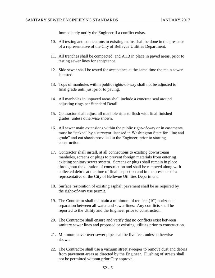
Immediately notify the Engineer if a conflict exists.
10. All testing and connections to existing mains shall be done in the presence
of a representative of the City of Bellevue Utilities Department.
11. All trenches shall be compacted, and ATB in place in paved areas, prior to
testing sewer lines for acceptance.
12. Side sewer shall be tested for acceptance at the same time the main sewer
is tested.
13. Tops of manholes within public rights-of-way shall not be adjusted to
final grade until just prior to paving.
14. All manholes in unpaved areas shall include a concrete seal around
adjusting rings per Standard Detail.
15. Contractor shall adjust all manhole rims to flush with final finished
grades, unless otherwise shown.
16. All sewer main extensions within the public right-of-way or in easements
must be “staked” by a surveyor licensed in Washington State for “line and
grade” and cut sheets provided to the Engineer, prior to starting
construction.
17. Contractor shall install, at all connections to existing downstream
manholes, screens or plugs to prevent foreign materials from entering
existing sanitary sewer system. Screens or plugs shall remain in place
throughout the duration of construction and shall be removed along with
collected debris at the time of final inspection and in the presence of a
representative of the City of Bellevue Utilities Department.
18. Surface restoration of existing asphalt pavement shall be as required by
the right-of-way use permit.
19. The Contractor shall maintain a minimum of ten feet (10') horizontal
separation between all water and sewer lines. Any conflicts shall be
reported to the Utility and the Engineer prior to construction.
20. The Contractor shall ensure and verify that no conflicts exist between
sanitary sewer lines and proposed or existing utilities prior to construction.
21. Minimum cover over sewer pipe shall be five feet, unless otherwise
shown.
22. The Contractor shall use a vacuum street sweeper to remove dust and debris
from pavement areas as directed by the Engineer. Flushing of streets shall
not be permitted without prior City approval.
SANITARY SEWER ENGINEERING STANDARDS JANUARY 2017
S2 - 6
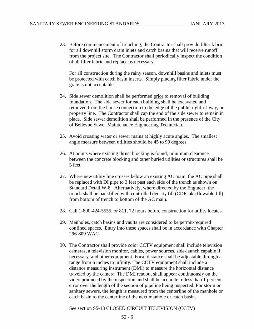
23. Before commencement of trenching, the Contractor shall provide filter fabric
for all downhill storm drain inlets and catch basins that will receive runoff
from the project site. The Contractor shall periodically inspect the condition
of all filter fabric and replace as necessary.
For all construction during the rainy season, downhill basins and inlets must
be protected with catch basin inserts. Simply placing filter fabric under the
grate is not acceptable.
24. Side sewer demolition shall be performed prior to removal of building
foundation. The side sewer for each building shall be excavated and
removed from the house connection to the edge of the public right-of-way, or
property line. The Contractor shall cap the end of the side sewer to remain in
place. Side sewer demolition shall be performed in the presence of the City
of Bellevue Sewer Maintenance Engineering Technician.
25. Avoid crossing water or sewer mains at highly acute angles. The smallest
angle measure between utilities should be 45 to 90 degrees.
26. At points where existing thrust blocking is found, minimum clearance
between the concrete blocking and other buried utilities or structures shall be
5 feet.
27. Where new utility line crosses below an existing AC main, the AC pipe shall
be replaced with DI pipe to 3 feet past each side of the trench as shown on
Standard Detail W-8. Alternatively, where directed by the Engineer, the
trench shall be backfilled with controlled density fill (CDF, aka flowable fill)
from bottom of trench to bottom of the AC main.
28. Call 1-800-424-5555, or 811, 72 hours before construction for utility locates.
29. Manholes, catch basins and vaults are considered to be permit-required
confined spaces. Entry into these spaces shall be in accordance with Chapter
296-809 WAC.
30. The Contractor shall provide color CCTV equipment shall include television
cameras, a television monitor, cables, power sources, side-launch capable if
necessary, and other equipment. Focal distance shall be adjustable through a
range from 6 inches to infinity. The CCTV equipment shall include a
distance measuring instrument (DMI) to measure the horizontal distance
traveled by the camera. The DMI readout shall appear continuously on the
video produced by the inspection and shall be accurate to less than 1 percent
error over the length of the section of pipeline being inspected. For storm or
sanitary sewers, the length is measured from the centerline of the manhole or
catch basin to the centerline of the next manhole or catch basin.
See section S5-13 CLOSED CIRCUIT TELEVISION (CCTV)

SANITARY SEWER ENGINEERING STANDARDS JANUARY 2017
S2 - 7
INSPECTION for Video formatting, naming, and delivery requirements.
The CCTV inspection system shall be performed utilizing one of the
following video camera systems:
Remote-focus stationary lens cameras;
Rotating lens cameras; or
Pan-and-tilt cameras.
The CCTV camera shall be mounted on a skid, floatable raft system, or
transporter based on the conditions of the pipeline to be televised.
Telephones, radios, or other suitable means of communication shall be
utilized to ensure communication exists between members of the crew. The
contractor shall inspect the pipeline during optimum low-flow level
conditions, as pre-approved by the Utility Inspector. The contractor shall
coordinate with the Utility Inspector prior to video inspection. The television
camera utilized shall be specifically designed and constructed for sewer
inspection. The camera shall be operative in 100 percent humidity conditions.
Lighting for the camera shall minimize reflective glare. Lighting and picture
quality shall be suitable to provide a clear, in-focus picture of the entire
periphery of the pipeline for all conditions encountered during the work. If
the quality of the video is deemed to be unacceptable by the Utility Inspector,
the pipeline shall be re-televised at no cost to the City. The camera shall be
moved through the pipeline at a uniform rate, stopping when necessary to
ensure proper documentation of the pipeline condition, but in no case shall
the television camera be pulled at a speed greater than 30 feet per minute
stopping when necessary to ensure proper documentation of the pipe
condition. The video shall be taken after installation, cleaning, and pressure
test to insure that no defects exist. The project will not be accepted until all
defects have been repaired.
31. When work is to occur in easements, the Contractor shall notify the easement
grantor and Bellevue Utilities in writing a minimum of 48 hours in advance
of beginning work (not including weekends or holidays). Failure to notify
grantor and Bellevue Utilities will result in a Stop Work Order being posted
until the matter is resolved to the satisfaction of Bellevue Utilities. A written
release from the easement grantor shall be furnished to the Utilities Inspector
prior to permit sign-off.
32. The Contractor shall restore the Right-of-Way and existing public sewer
easement(s) after construction to a condition equal or better than condition
prior to entry. The Contractor shall furnish a signed release from all affected
property owners after restoration has been completed.
S2-05 AS-BUILT DOCUMENTATION
For all wastewater projects, the Developer or City Department responsible for the project
shall provide as-built plans at completion of the project.
SANITARY SEWER ENGINEERING STANDARDS JANUARY 2017
S2 - 8
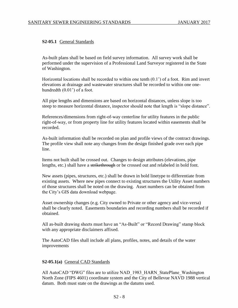
S2-05.1 General Standards
As-built plans shall be based on field survey information. All survey work shall be
performed under the supervision of a Professional Land Surveyor registered in the State
of Washington.
Horizontal locations shall be recorded to within one tenth (0.1’) of a foot. Rim and invert
elevations at drainage and wastewater structures shall be recorded to within one one-
hundredth (0.01’) of a foot.
All pipe lengths and dimensions are based on horizontal distances, unless slope is too
steep to measure horizontal distance, inspector should note that length is “slope distance”.
References/dimensions from right-of-way centerline for utility features in the public
right-of-way, or from property line for utility features located within easements shall be
recorded.
As-built information shall be recorded on plan and profile views of the contract drawings.
The profile view shall note any changes from the design finished grade over each pipe
line.
Items not built shall be crossed out. Changes to design attributes (elevations, pipe
lengths, etc.) shall have a strikethrough or be crossed out and relabeled in bold font.
New assets (pipes, structures, etc.) shall be drawn in bold linetype to differentiate from
existing assets. Where new pipes connect to existing structures the Utility Asset numbers
of those structures shall be noted on the drawing. Asset numbers can be obtained from
the City’s GIS data download webpage.
Asset ownership changes (e.g. City owned to Private or other agency and vice-versa)
shall be clearly noted. Easements boundaries and recording numbers shall be recorded if
obtained.
All as-built drawing sheets must have an “As-Built” or “Record Drawing” stamp block
with any appropriate disclaimers affixed.
The AutoCAD files shall include all plans, profiles, notes, and details of the water
improvements
S2-05.1(a) General CAD Standards
All AutoCAD “DWG” files are to utilize NAD_1983_HARN_StatePlane_Washington
North Zone (FIPS 4601) coordinate system and the City of Bellevue NAVD 1988 vertical
datum. Both must state on the drawings as the datums used.
SANITARY SEWER ENGINEERING STANDARDS JANUARY 2017
S2 - 9
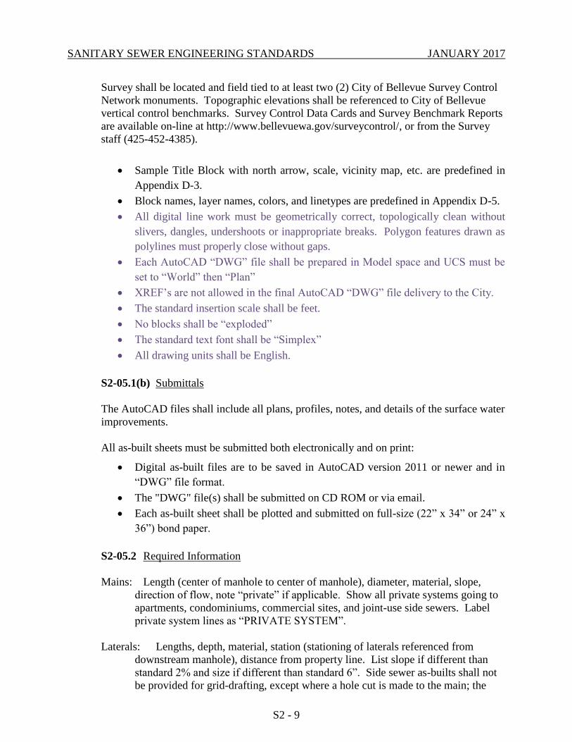
Survey shall be located and field tied to at least two (2) City of Bellevue Survey Control
Network monuments. Topographic elevations shall be referenced to City of Bellevue
vertical control benchmarks. Survey Control Data Cards and Survey Benchmark Reports
are available on-line at http://www.bellevuewa.gov/surveycontrol/, or from the Survey
staff (425-452-4385).
Sample Title Block with north arrow, scale, vicinity map, etc. are predefined in
Appendix D-3.
Block names, layer names, colors, and linetypes are predefined in Appendix D-5.
All digital line work must be geometrically correct, topologically clean without
slivers, dangles, undershoots or inappropriate breaks. Polygon features drawn as
polylines must properly close without gaps.
Each AutoCAD “DWG” file shall be prepared in Model space and UCS must be
set to “World” then “Plan”
XREF’s are not allowed in the final AutoCAD “DWG” file delivery to the City.
The standard insertion scale shall be feet.
No blocks shall be “exploded”
The standard text font shall be “Simplex”
All drawing units shall be English.
S2-05.1(b) Submittals
The AutoCAD files shall include all plans, profiles, notes, and details of the surface water
improvements.
All as-built sheets must be submitted both electronically and on print:
Digital as-built files are to be saved in AutoCAD version 2011 or newer and in
“DWG” file format.
The "DWG" file(s) shall be submitted on CD ROM or via email.
Each as-built sheet shall be plotted and submitted on full-size (22” x 34” or 24” x
36”) bond paper.
S2-05.2 Required Information
Mains: Length (center of manhole to center of manhole), diameter, material, slope,
direction of flow, note “private” if applicable. Show all private systems going to
apartments, condominiums, commercial sites, and joint-use side sewers. Label
private system lines as “PRIVATE SYSTEM”.
Laterals: Lengths, depth, material, station (stationing of laterals referenced from
downstream manhole), distance from property line. List slope if different than
standard 2% and size if different than standard 6”. Side sewer as-builts shall not
be provided for grid-drafting, except where a hole cut is made to the main; the
SANITARY SEWER ENGINEERING STANDARDS JANUARY 2017
S2 - 10
Inspector shall show saddle and lateral.
Manholes: Type (drop if applicable), rim elevation, invert elevations (indicate direction
of flow IN or OUT), size (diameter).
Cleanouts: Station, invert elevation, top elevation, note if to grade.
Fittings: Type (e.g. wye, tee, reducer).
Structures: Where new pipes connect to existing manholes, the Utilities ID number of
the existing manhole shall be noted on the drawing. ID numbers can be obtained
from the Sewer Grid Maps.
END OF CHAPTER S2

SANITARY SEWER ENGINEERING STANDARDS JANUARY 2017
CHAPTER S3 – SEWER PLANNING/DESIGN STANDARDS
TABLE OF CONTENTS
S3-01 PLANNING CRITERIA ........................................................................ S3 - 1
S3-02 GENERAL DESIGN STANDARDS .................................................... S3 - 2
S3-03 MAIN LINES......................................................................................... S3 - 3
S3-04 MANHOLES ......................................................................................... S3 - 4
S3-05 PIPE CLASS – PROTECTION – COVER ........................................... S3 - 7
S3-06 CLEARANCES – OTHER UTILITIES ................................................ S3 - 8
S3-07 CONNECTIONS TO EXISTING SYSTEM ......................................... S3 - 9
S3-08 FATS, OILS, GREASE SEPARATION ............................................. S3 - 10
S3-09 EASEMENTS ...................................................................................... S3 - 12
S3-10 SIDE SEWERS .................................................................................... S3 - 14
SANITARY SEWER ENGINEERING STANDARDS JANUARY 2017
S3 - 1
CHAPTER S3 - SEWER PLANNING/DESIGN STANDARDS
S3-01 PLANNING CRITERIA
S3-01.1 Serve to Extreme of Property
Ensure adjacent properties can be provided sewer service (extend to extreme of property
and design for the ultimate development of the tributary areas).
Sewer service shall be provided by a gravity system (unless approved by the Utility).
S3-01.2 Demand Projections
Demand projections are taken from City of Bellevue 2013 Waste Water System Plan:
A. Unit Demands
Residential - 65 gallons per capita per day (GPCD)
Commercial- 25 GPCD
B. Population Densities
2.7 People per single family unit
2 People per multi-family unit
C. Peaking Factors
1. Where average day demands are between 0 and 1050 gpm, the
design peaking factor will vary linearly between 4 and 2.5
respectively.
2. Where average day demands are greater than 1050 gpm the design
peaking shall be 2.5.
S3-01.3 Infiltration/Inflow (I/I) Allowances
A. For new systems; I/I allowance of 1100 gallons per acre per day (GPAD)
shall be used.
B. On existing sewer systems, I/I allowance shall be determined through
analysis.
S3-01.4 System Parameters
A. New sewer lines shall be designed so that, under ultimate development, peak
flow, including I/I, shall not exceed 50% capacity of the line. Existing lines
can have peak flows to 75% capacity of the line. Bellevue Utilities
Department, Planning Section staff will model sewer capacity needs and
SANITARY SEWER ENGINEERING STANDARDS JANUARY 2017
S3 - 2
determine ultimate peak flows. Engineering design submittals must conform
to the City’s required minimum pipe sizes and generally accepted industry
standards.
B. No storm drainage connections shall be made to the sanitary sewer system,
unless approved by the Utility and only under special circumstances, i.e.
covered parking or wash down areas around garbage collection dumpsters
with an area less than 200 square feet.
All garbage dumpster areas, regardless of size, shall discharge to sewer after
passing through an oil/water separator. Garbage dumpster areas under 200
square feet may be uncovered if designed pursuant to Standard Detail S-32.
Garbage dumpster areas 200 square feet and larger must be covered; the floor
area draining to the sewer and the roof area draining to the storm. Refer to
the City of Bellevue Surface Water Engineering Standards.
S3-02 GENERAL DESIGN STANDARDS
A. All lengths and dimensions shall be horizontal distances, no slope distances on
plans.
B. If working in existing streets, indicate type of pavement restoration required, or
refer to Right-of-way use permit.
C. Dimension existing and new main locations from right-of-way line and/or
property line, or label stations and offsets.
D. Check with Utility Development Division to determine how surrounding
development will affect design (e.g. serve to extreme of property if adjacent
property has potential for future development).
E. On plans, show existing manholes or give reference distances to existing
manholes near project, including manhole number and invert/rim elevations.
F. Check with local jurisdiction for necessary permitting requirements.
G. Existing sewer lines to be abandoned shall be filled completely with sand,
concrete, or controlled density fill; or removed.
H. Manholes connected to lines being abandoned shall be re-channeled with 3,000
psi cement concrete.
I. Side sewers and sewer mains shall not be used for the grounding of electrical
systems or for the maintenance, integrity or continuity of any grounding
attachment or connection.
SANITARY SEWER ENGINEERING STANDARDS JANUARY 2017
S3 - 3
J. Placement of surface appurtenances (manhole lids, water valve lids, etc.) in tire
track of traffic lanes shall be avoided whenever possible.
K. Soil nails shall not be installed at or above pipes and shall include a minimum 5
foot clearance if installed below pipes.
S3-03 MAIN LINES
S3.03.1 Minimum Pipe Size
Minimum pipe size shall be 8 inches.
S3-03.2 Pipe Slope
A. Minimum slope shall be 0.01 ft/ft. Where slopes of 0.01 ft/ft do not allow an
area to be served by gravity flow, the minimum slope shall be 0.005 ft/ft.
B. Maximum main line slope shall not induce velocities greater than 10 feet per
second under daily peak flows.
C. Pipe anchor blocks shall be placed at 20' on center where pipe slope exceeds
20%.
D. Timber baffle/hill holders shall be required on unpaved slopes that exceed
20%, minimum spacing shall be 20' on center.
S3-03.3 Plan View
A. List pipe length, size and material alongside of pipe, e.g. 150 L.F.- 8" PVC.
Pipe material can be listed in a general note in lieu of listing along pipe.
B. Pipe length is to be based on horizontal distance between center of manholes.
C. Indicate direction of flow with arrows on end of pipe entering manhole.
S3-03.4 Profile View
A. List pipe length, size, material and slope to 4 decimal places (ft per ft), e.g.
150 L.F. - 8" PVC S=0.0125. Pipe material can be listed in a general note in
lieu of listing on profile.
B. Slope is based on I.E. OUT of upstream manhole, I.E. INTO downstream
manhole and horizontal distance between center of manholes.
SANITARY SEWER ENGINEERING STANDARDS JANUARY 2017
S3 - 4
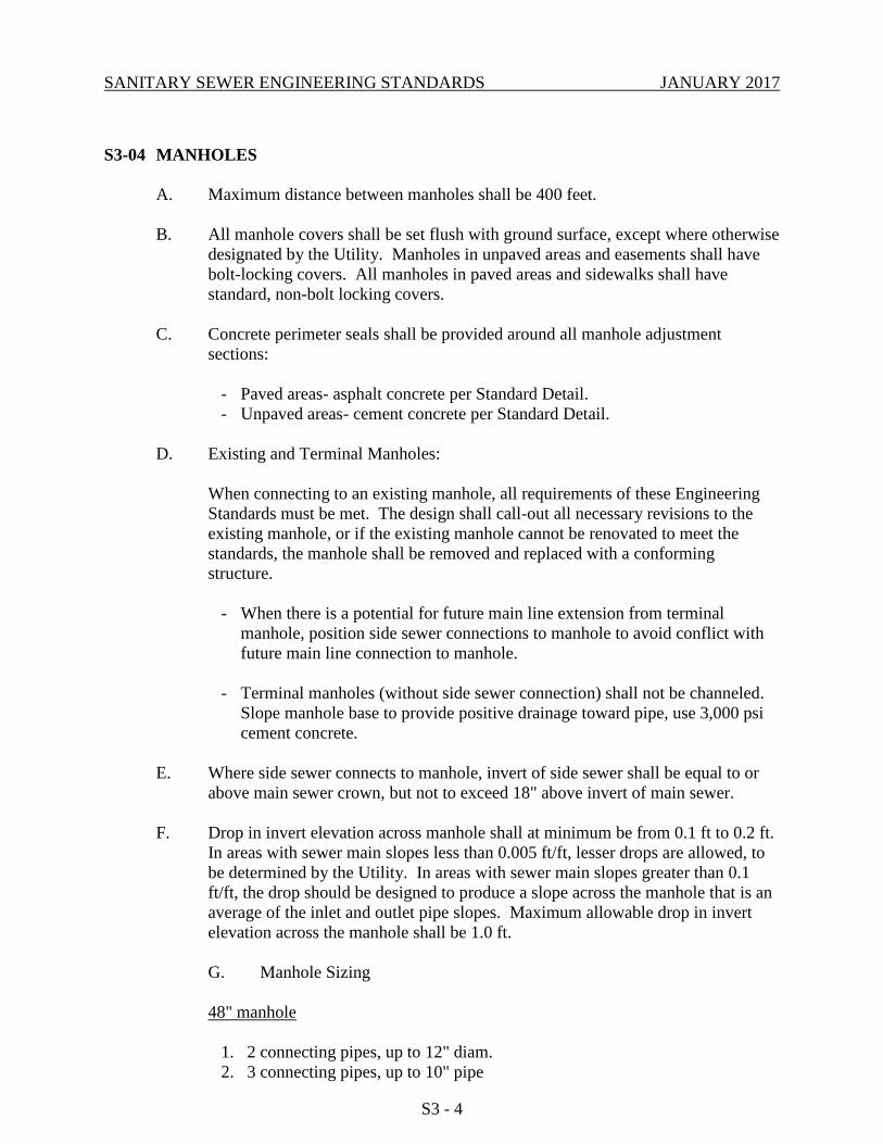
S3-04 MANHOLES
A. Maximum distance between manholes shall be 400 feet.
B. All manhole covers shall be set flush with ground surface, except where otherwise
designated by the Utility. Manholes in unpaved areas and easements shall have
bolt-locking covers. All manholes in paved areas and sidewalks shall have
standard, non-bolt locking covers.
C. Concrete perimeter seals shall be provided around all manhole adjustment
sections:
- Paved areas- asphalt concrete per Standard Detail.
- Unpaved areas- cement concrete per Standard Detail.
D. Existing and Terminal Manholes:
When connecting to an existing manhole, all requirements of these Engineering
Standards must be met. The design shall call-out all necessary revisions to the
existing manhole, or if the existing manhole cannot be renovated to meet the
standards, the manhole shall be removed and replaced with a conforming
structure.
- When there is a potential for future main line extension from terminal
manhole, position side sewer connections to manhole to avoid conflict with
future main line connection to manhole.
- Terminal manholes (without side sewer connection) shall not be channeled.
Slope manhole base to provide positive drainage toward pipe, use 3,000 psi
cement concrete.
E. Where side sewer connects to manhole, invert of side sewer shall be equal to or
above main sewer crown, but not to exceed 18" above invert of main sewer.
F. Drop in invert elevation across manhole shall at minimum be from 0.1 ft to 0.2 ft.
In areas with sewer main slopes less than 0.005 ft/ft, lesser drops are allowed, to
be determined by the Utility. In areas with sewer main slopes greater than 0.1
ft/ft, the drop should be designed to produce a slope across the manhole that is an
average of the inlet and outlet pipe slopes. Maximum allowable drop in invert
elevation across the manhole shall be 1.0 ft.
G. Manhole Sizing
48" manhole
1. 2 connecting pipes, up to 12" diam.
2. 3 connecting pipes, up to 10" pipe
SANITARY SEWER ENGINEERING STANDARDS JANUARY 2017
S3 - 5
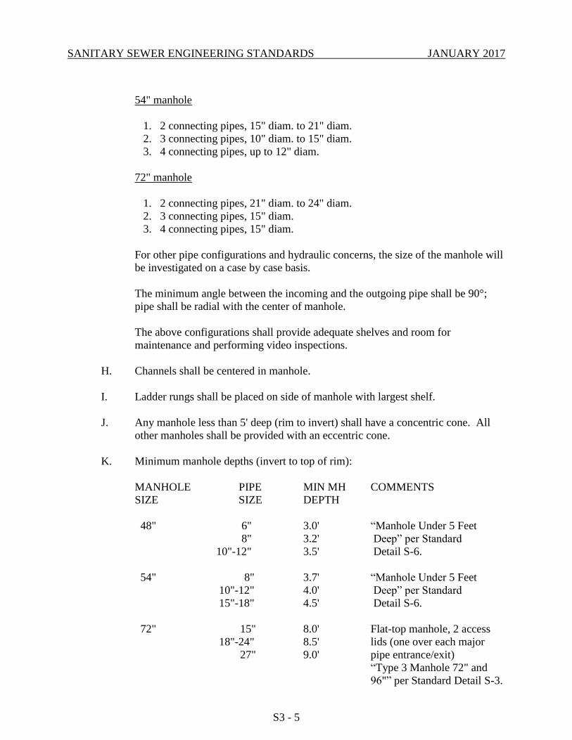
54" manhole
1. 2 connecting pipes, 15" diam. to 21" diam.
2. 3 connecting pipes, 10" diam. to 15" diam.
3. 4 connecting pipes, up to 12" diam.
72" manhole
1. 2 connecting pipes, 21" diam. to 24" diam.
2. 3 connecting pipes, 15" diam.
3. 4 connecting pipes, 15" diam.
For other pipe configurations and hydraulic concerns, the size of the manhole will
be investigated on a case by case basis.
The minimum angle between the incoming and the outgoing pipe shall be 90°;
pipe shall be radial with the center of manhole.
The above configurations shall provide adequate shelves and room for
maintenance and performing video inspections.
H. Channels shall be centered in manhole.
I. Ladder rungs shall be placed on side of manhole with largest shelf.
J. Any manhole less than 5' deep (rim to invert) shall have a concentric cone. All
other manholes shall be provided with an eccentric cone.
K. Minimum manhole depths (invert to top of rim):
MANHOLE PIPE MIN MH COMMENTS
SIZE SIZE DEPTH
48" 6" 3.0' “Manhole Under 5 Feet
8" 3.2' Deep” per Standard
10"-12" 3.5' Detail S-6.
54" 8" 3.7' “Manhole Under 5 Feet
10"-12" 4.0' Deep” per Standard
15"-18" 4.5' Detail S-6.
72" 15" 8.0' Flat-top manhole, 2 access
18"-24" 8.5' lids (one over each major
27" 9.0' pipe entrance/exit)
“Type 3 Manhole 72" and
96"” per Standard Detail S-3.
SANITARY SEWER ENGINEERING STANDARDS JANUARY 2017
S3 - 6
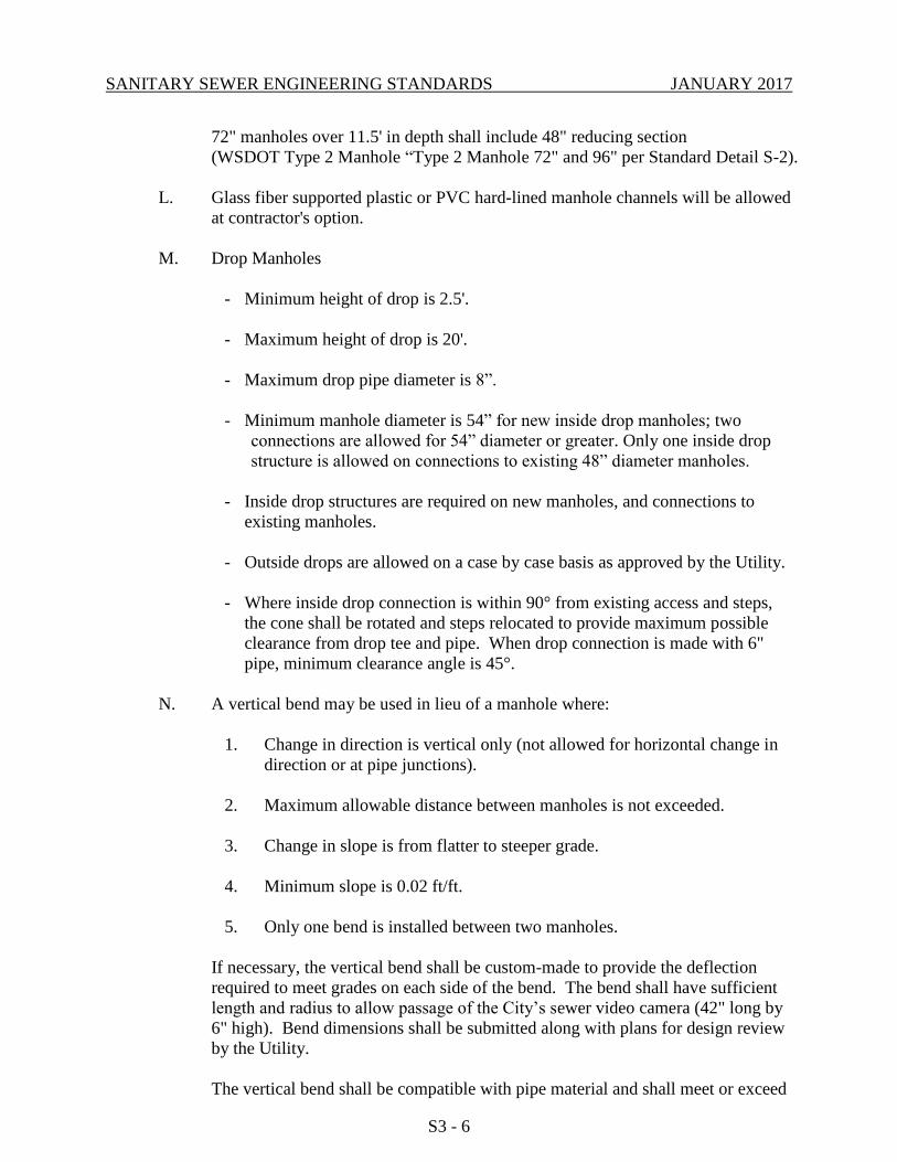
72" manholes over 11.5' in depth shall include 48" reducing section
(WSDOT Type 2 Manhole “Type 2 Manhole 72" and 96" per Standard Detail S-2).
L. Glass fiber supported plastic or PVC hard-lined manhole channels will be allowed
at contractor's option.
M. Drop Manholes
- Minimum height of drop is 2.5'.
- Maximum height of drop is 20'.
- Maximum drop pipe diameter is 8”.
- Minimum manhole diameter is 54” for new inside drop manholes; two
connections are allowed for 54” diameter or greater. Only one inside drop
structure is allowed on connections to existing 48” diameter manholes.
- Inside drop structures are required on new manholes, and connections to
existing manholes.
- Outside drops are allowed on a case by case basis as approved by the Utility.
- Where inside drop connection is within 90° from existing access and steps,
the cone shall be rotated and steps relocated to provide maximum possible
clearance from drop tee and pipe. When drop connection is made with 6"
pipe, minimum clearance angle is 45°.
N. A vertical bend may be used in lieu of a manhole where:
1. Change in direction is vertical only (not allowed for horizontal change in
direction or at pipe junctions).
2. Maximum allowable distance between manholes is not exceeded.
3. Change in slope is from flatter to steeper grade.
4. Minimum slope is 0.02 ft/ft.
5. Only one bend is installed between two manholes.
If necessary, the vertical bend shall be custom-made to provide the deflection
required to meet grades on each side of the bend. The bend shall have sufficient
length and radius to allow passage of the City’s sewer video camera (42" long by
6" high). Bend dimensions shall be submitted along with plans for design review
by the Utility.
The vertical bend shall be compatible with pipe material and shall meet or exceed
SANITARY SEWER ENGINEERING STANDARDS JANUARY 2017
S3 - 7
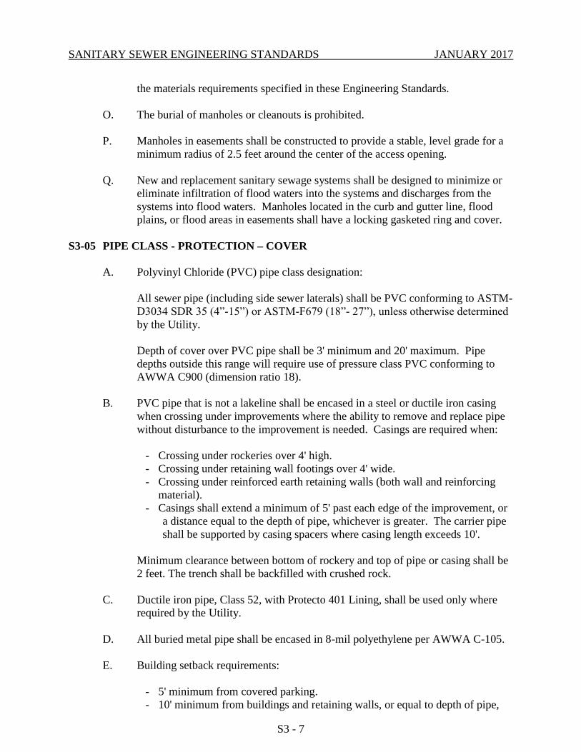
the materials requirements specified in these Engineering Standards.
O. The burial of manholes or cleanouts is prohibited.
P. Manholes in easements shall be constructed to provide a stable, level grade for a
minimum radius of 2.5 feet around the center of the access opening.
Q. New and replacement sanitary sewage systems shall be designed to minimize or
eliminate infiltration of flood waters into the systems and discharges from the
systems into flood waters. Manholes located in the curb and gutter line, flood
plains, or flood areas in easements shall have a locking gasketed ring and cover.
S3-05 PIPE CLASS - PROTECTION – COVER
A. Polyvinyl Chloride (PVC) pipe class designation:
All sewer pipe (including side sewer laterals) shall be PVC conforming to ASTM-
D3034 SDR 35 (4”-15”) or ASTM-F679 (18”- 27”), unless otherwise determined
by the Utility.
Depth of cover over PVC pipe shall be 3' minimum and 20' maximum. Pipe
depths outside this range will require use of pressure class PVC conforming to
AWWA C900 (dimension ratio 18).
B. PVC pipe that is not a lakeline shall be encased in a steel or ductile iron casing
when crossing under improvements where the ability to remove and replace pipe
without disturbance to the improvement is needed. Casings are required when:
- Crossing under rockeries over 4' high.
- Crossing under retaining wall footings over 4' wide.
- Crossing under reinforced earth retaining walls (both wall and reinforcing
material).
- Casings shall extend a minimum of 5' past each edge of the improvement, or
a distance equal to the depth of pipe, whichever is greater. The carrier pipe
shall be supported by casing spacers where casing length exceeds 10'.
Minimum clearance between bottom of rockery and top of pipe or casing shall be
2 feet. The trench shall be backfilled with crushed rock.
C. Ductile iron pipe, Class 52, with Protecto 401 Lining, shall be used only where
required by the Utility.
D. All buried metal pipe shall be encased in 8-mil polyethylene per AWWA C-105.
E. Building setback requirements:
- 5' minimum from covered parking.
- 10' minimum from buildings and retaining walls, or equal to depth of pipe,

SANITARY SEWER ENGINEERING STANDARDS JANUARY 2017
S3 - 8
whichever is greater.
- 20' minimum easement shall be provided between buildings, on multi-family
and commercial sites.
- When passing between any two buildings (residential or commercial, etc.)
which are 25' apart or less, the easement width shall extend the full width
between the buildings and the depth of the sewer line shall not exceed 10'.
F. Lakeline requirements:
Pressure (C900) Polyvinyl Chloride (PVC) Pipe shall be used at all times,
unless specified otherwise, and shall meet the requirements of ANSI/AWWA
C900 or ANSI/AWWA C905. C900 PVC pipe shall have the same outside
dimensions as ductile iron pipe. Ductile iron pipe, Class 52, with Protecto
401 lining, shall be used where the pipeline is exposed, supported by pilings,
or when required by the Utility.
S3-06 CLEARANCES - OTHER UTILITIES
A. All clearances listed below are from edge-to-edge of each pipe.
B. Water services and sewer laterals shall have at least 5' horizontal clearance.
C. Check for crossing or parallel utilities. Maintain minimum vertical and horizontal
clearances. Avoid crossing at highly acute angles (the smallest angle measure
between utilities should be between 45 and 90°).
D. Horizontal clearances from sanitary sewer:
Cable TV 5'
Gas 5'
Power 10'
Storm 5'
Telephone, Fiber Optic 10'
Water 10'
E. Vertical clearances from sanitary sewer:
Cable TV 1'
Gas 1'
Power 1'
Storm 1'
Telephone, Fiber Optic 1'
Water 2'
F. Where sewer crosses above or below water main, one full length of sewer pipe
shall be used with the pipes centered for maximum joint separation. Washington
Department of Ecology criteria will also apply.
SANITARY SEWER ENGINEERING STANDARDS JANUARY 2017
S3 - 9
G. Send letter and preliminary plan to existing utilities to inform them of new
construction. Request as-built information and incorporate into plans. At
minimum the following utilities should be contacted:
Cable television
Natural gas
Power
Storm drainage
Telephone, Fiber Optic
Water
H. Seattle Public Utilities Transmission Pipelines: See Appendix S-5, Sanitary Sewer
Reference Standards; Standards for Utilities Installed in Proximity of Seattle
Public Utilities Transmission Pipelines.
S3-07 CONNECTIONS TO EXISTING SYSTEM
A. New sewer mains (8" and larger) shall connect to existing sewer main at existing
manholes, or with new manhole on existing sewer per Standard Details.
B. When connecting to existing manhole, core-drill opening for pipe and re-channel
manhole base.
C. Where new main is larger in diameter than existing downstream main, check that
capacity of existing main is not exceeded by flow from new main.
D. When connecting to existing manhole, check that requirements of Section S3-
04.G are satisfied.
E. If connecting to existing manhole which has access less than 24" in diameter
and/or concentric cone (manholes less than 5' deep), manhole shall be upgraded to
include new 24" ring and cover and/or eccentric cone.
F. If connection to existing manhole places a channel directly under access opening,
move ladder and rotate cone section to place access over concrete shelf.
G. Connections to end of existing pipe:
- If end of pipe is known to have a bell, and new pipe is same material as
existing, plans can specify connection by inserting spigot of new pipe into
existing bell end, with “donut” gasket.
- If existing line is plain end, or must be cut, plans shall specify use of a
coupling to connect new and existing lines.
H. Approved couplings for use on sewer mains include:
Ductile iron mechanical couplings (equal to ROMAC) on ductile iron, concrete,
vitrified clay, or pipes with differing materials or diameters.
SANITARY SEWER ENGINEERING STANDARDS JANUARY 2017
S3 - 10
On PVC or PE mains, PVC or PE couplings with compatible dimension ratio and
gaskets to connect new and existing pipes shall be used.
Where a section of existing PVC pipe is replaced by “dropping-in” a new section
of PVC pipe, the connections to existing pipe shall be made with PVC closure
couplings (slip couplings).
S3-08 FATS, OILS, GREASE SEPARATION
S3-08.1 Oil/Water Separator
Whenever an industrial or commercial business generates mineral/petroleum/non-
biodegradable cutting oils exceeding 100 milligrams per liter to be discharged to the
sanitary sewer, pre-treatment is required. An oil/water separation device shall be installed
by the property owner as specified on various Standard Details. Selection and sizing of an
oil/water separator shall be subject to approval of the Utility. Water discharged from any
oil/water separator to the sanitary sewer system shall not contain in excess of 100
milligrams per liter of petroleum oil, non-biodegradable cutting oil and mineral products,
and shall be in compliance with the City of Bellevue and King County Wastewater
regulations for discharge to the sanitary sewer.
A. Sizing of a separator facility shall be based upon maximum available flow to
the separator and provision of a forty-five minute retention time in the
separator at that flow, with a minimum capacity of at least 100 gallons.
B. The oil/water separator shall be covered with removable sections. Access
and inspection covers, weighing not more than 30 lbs. and with suitable hand
holds, are to be provided directly above inspection “tee” and oil/grit
collection compartments.
C. Only waste water from floor drains and covered parking areas shall drain to
the separator. The location and design shall minimize or eliminate the
possibility of storm water reaching the separator -- areas over two hundred
square feet open to rainfall shall not drain to the separator. Sewage from
restrooms and shower facilities shall not drain to the separator. See Standard
Details.
D. Allowable materials for construction are as follows:
- Tank – concrete
- Baffles - concrete, steel plate
E. The separator shall be located within 20 feet of drive for access by
maintenance vehicle.
F. A sampling tee shall be located on the outlet as shown on the Standard
Details. Access to the separator shall be maintained free for inspection and
compliance determination sampling at all times.
SANITARY SEWER ENGINEERING STANDARDS JANUARY 2017
S3 - 11
G. The effluent discharged from any oil/water separator to the sanitary sewer
shall not exceed 100 parts per million total oil.
H. When pre-treatment is no longer required, the inlet and outlet pipes shall be
permanently plugged, the separation chambers pumped out, and the vault
removed, or filled with compacted crushed rock or controlled density fill.
S3-08.2 Grease Interceptor
Whenever a commercial and/or retail food preparation operation, regardless of size,
generates animal/vegetable fats, oils or grease (F.O.G.) waste, which causes a visible
sheen or accumulations in the effluent, to be discharged to the sanitary sewer,
pre-treatment is required. A grease interception device as specified by the City of
Bellevue Standard Details, and/or other biological, chemical, or other pretreatment
approved by the Utility, shall be installed by the owner. Effluent discharged from any
grease interceptor shall not contain a visible sheen or accumulations of F.O.G., and shall
be in compliance with the City of Bellevue and King County Wastewater regulations for
discharge to the sanitary sewer.
A. Design of the grease interceptor shall conform to the Standard Details, and
shall be subject to approval by the Utility. Size shall be determined by the
City of Bellevue, F.O.G. Administrator. Minimum capacity shall be 600
gallons except as noted by the City of Bellevue.
B. Fixtures in the kitchen area which discharge waste-water containing grease
are to be connected to the grease interceptor. Such fixtures include
dishwashers, pot sinks, range woks, janitor's sink, floor sinks, and rotoclones.
Toilets, urinals, and wash basins shall not flow through the interceptor.
C. The interceptor shall be located outside the building within twenty feet of
drive for access by maintenance vehicles.
D. The interceptor shall be filled with clean water prior to start-up of system.
E. Allowable materials for construction are as follows:
- Tank – concrete
- Baffles - concrete, plastic
F. Access to the interceptor shall be maintained free for inspection and
compliance determination sampling at all times.
G. When pre-treatment is no longer required, the inlet and outlet pipes shall be
permanently plugged, the separation chambers pumped out, and the vault
removed, or filled with compacted crushed rock or controlled density fill.
S3-09 EASEMENTS
SANITARY SEWER ENGINEERING STANDARDS JANUARY 2017
S3 - 12
A. Show easements on all plans and identify width.
B. Show easements on all private property. If easement is defined as a constant
width on each side of sewer main, then show a segment of the easement and label
as typical (typ).
C. The required utility easement width shall be: 1) the minimum value set forth
below; or, 2) determined by extending a line from the bottom of the excavation at
the outside diameter for pipes, at a 1 H : IV slope until it intercepts the finished
grade, whichever is greater.
D. The sewer pipe shall be located in the center of the easement.
E. For pipes up to 18 inches in diameter, the minimum easement width shall be 15
feet.
F. For pipes greater than 18 inches, the minimum easement width shall be 20 feet.
G. A 20 foot minimum easement shall be provided between buildings, on multi-
family and commercial sites.
H. When passing between any two buildings (residential or commercial, etc.) which
are 25 feet apart or less, the easement width shall extend the full width between
the buildings and the depth of the sewer pipe shall not exceed 10 feet.
I. Sewer pipe shall be located 10 feet from edge of easement facing interior of lot, to
ensure setback from building.
J. Also see Section S3-05.E, “Building Setback Requirements”.
K. Easement Documentation Requirements:
- All easements shall be shown on the project plans and identified as “private”
or “public”, together with the width dimension and utility use, e.g. 20’Public
Sewer Utility Easement.
- All documents for public easements shall conform to these Utilities
Engineering Standards, will be provided on the City’s easement template
and shall comply with King County Recorder’s Office formatting
requirements. Include the King County tax parcel number(s), site address,
owner names and site legal description. All pages must be numbered.
Sheets shall be 8-1/2” by 11” or 8-1/2” by 14”. Margins and font size must
conform to King County recording format requirements.
- Easements shall be dedicated to and approved by the City prior to acceptance
of a public utility system. The Grantee shall be the “CITY OF BELLEVUE,
a Washington municipal corporation, its heirs, successors and assigns”. The

SANITARY SEWER ENGINEERING STANDARDS JANUARY 2017
S3 - 13
City may require indemnification agreements to hold the City harmless
where maintenance access across private property is deemed necessary.
- The description contained within the easement document shall be prepared
and stamped by a land surveyor licensed in the State of Washington. The
description shall be identified as an Exhibit, together with the title of the
utility use, e.g. Permanent Public Sewer Utility Easement. The description
shall be clearly written and referenced to the underlying property. The
description shall be accompanied by an additional graphic Exhibit which
depicts a scaled drawing of the easement location relative to the subject
parcel.
- Off-site easements shall be delivered to the Utility prior to issuing a
Notification to Proceed with construction. Submittal of on-site easements
may be delayed until completion of construction improvements.
- Bills of Sale for all utility facilities appurtenant to public easements or tracts
shall be given to the City.
S3-10 SIDE SEWERS
A. Side sewer lateral shall extend from main line to 10' past edge of property line. 6"
pipe shall be used inside the public right-of-way (unless expected flows require
larger size line).
B. 4" minimum pipe may be used inside private property, for residential side sewers
from end of 6" lateral to building, for a single connection contained within the lot.
6" minimum pipe shall be used for private joint-use sewers, and when crossing a
property outside the lot to be served.
Commercial side sewers shall be a minimum 6" pipe.
For multi-family developments, side sewers for each separate building must be at
least 6-inches in diameter. For those buildings serving over ten units or for side
sewers serving more than one building, side sewers shall be a minimum of 8-
inches in diameter and must connect to a manhole.
C. Side sewer shall have minimum 6' of cover at property line. Greater depths may
be required where elevation of lowest floor to be served is lower than surface
elevation at property line. Ensure that lateral can serve all property by gravity
flow.
D. Joint-use side sewer laterals are not allowed where slope of side sewer is less than
2%. Provide a single lateral to “low” end of each lot, and show invert elevation of
each lateral on the plan. 2012 Uniform Plumbing Code may also require a
backwater valve.
SANITARY SEWER ENGINEERING STANDARDS JANUARY 2017
S3 - 14
E. Side sewers shall connect to main sewers with a tee rather than a wye, unless
otherwise approved by the Utility. Side sewer laterals shall run perpendicular to
the sewer main, in the right-of-way. On plan, indicate station of side sewer tee
from nearest downstream manhole. Also indicate length of side sewer lateral
from main to cap at end of line. Call out invert at capped-end of lateral.
F. Minimum side sewer slope shall be 2 percent. Maximum slope shall be 100
percent.
G. All side sewer clean-outs on commercial and multi-family projects shall include
at-grade access with covers per the Standard Detail.
H. Maximum distance between side sewer clean-outs shall be 100 feet.
I. See Section S6-09, Joint-Use Side Sewer, for additional requirements for single-
family residential joint-use side sewers.
J. For a side sewer connection to a building where a coupling is within the right-of-
way and when the edge of the building foundation is at or within 3 feet of the
edge of right-of-way, the coupling shall be a ductile iron mechanical coupling,
equal to Romac 501 style.
END OF CHAPTER S3
SANITARY SEWER ENGINEERING STANDARDS JANUARY 2017
CHAPTER S4 – SEWER MATERIALS
TABLE OF CONTENTS
S4-01 GENERAL ............................................................................................. S4 - 1
S4-02 GRAVITY SEWER PIPE & FITTINGS ............................................... S4 - 1
S4-03 PRESSURE SEWER PIPE .................................................................... S4 - 2
S4-04 HDPE PIPE ............................................................................................ S4 - 3
S4-05 ABS PIPE & FITTINGS ........................................................................ S4 - 3
S4-06 FITTINGS .............................................................................................. S4 - 3
S4-07 CAPS AND PLUGS .............................................................................. S4 - 3
S4-08 BOLTS IN PIPING ................................................................................ S4 - 3
S4-09 FLANGE GASKETS ............................................................................. S4 - 4
S4-10 GATE VALVE ...................................................................................... S4 - 4
S4-11 VALVE BOX......................................................................................... S4 - 4
S4-12 VALVE OPERATING NUT EXTENSION .......................................... S4 - 4
S4-13 MANHOLES ......................................................................................... S4 - 4
S4-14 MANHOLE LINING ............................................................................. S4 - 5
S4-15 MANHOLE RING & COVER .............................................................. S4 - 5
S4-16 CONCRETE BEDDING & BLOCKING .............................................. S4 - 6
S4-17 OIL/WATER SEPARATOR ................................................................. S4 - 6
S4-18 GREASE INTERCEPTOR .................................................................... S4 – 6
S4-19 LIDS, HATCHES AND COVERS – SLIP RESISTANCE .................. S4 - 7
S4-20 COMMERCIAL CLEAN-OUT WITH TEST SAMPLING TEE ......... S4 - 7
S4-21 BACKWATER VALVE ........................................................................ S4 - 7
S4-22 MECHANICAL SEWER PLUG FOR LAKELINE CLEAN-OUT ..... S4 – 7
SANITARY SEWER ENGINEERING STANDARDS JANUARY 2017
S4-23 BARRIER FENCE................................................................................. S4 - 8
S4-24 BEDDING AND BACKFILL ............................................................... S4 - 8
S4-25 STEEL CASING .................................................................................. S4 - 10
S4-26 CASING SPACER............................................................................... S4 - 11
S4-27 NEOPRENE FOAM PAD ................................................................... S4 - 12

SANITARY SEWER ENGINEERING STANDARDS JANUARY 2017
S4 - 1
CHAPTER S4 - SEWER MATERIALS
S4-01 GENERAL
All materials shall be new and undamaged. The same manufacturer of each item shall be used
throughout the work.
Where reference is made to other specifications, it shall be the latest revision at the time of
construction, except as noted on the plans or herein.
All materials not specifically referenced shall comply with applicable sections of ASTM,
AWWA or the APWA/WSDOT Standard Specifications.
Approved manufacturers and model numbers of various materials are listed in Approved
Materials List, Appendix S-4. When specific manufacturers or models are listed, no
substitutions will be allowed without prior approval by the Utility.
S4-02 GRAVITY SEWER PIPE & FITTINGS
4" to 15" Diameter PVC Pipe:
All PVC pipe and fittings shall be integral wall bell and spigot, rubber gasket joint, unplasticized
Polyvinyl chloride (PVC) pipe. All PVC pipe shall have a minimum "pipe stiffness" of 46 psi at
5 percent deflection at 73° F when tested in accordance with ASTM Designation D-2412,
external loading properties of plastic pipe; and a minimum impact strength based on ASTM D-
3034 at 73° F using a 20 pound Tup A.
All PVC sewer pipe and fittings manufacture and installation shall meet or exceed the ASTM
recommended specifications D-3034, SDR 35, unless otherwise specified, and all installation
shall be in strict compliance with the manufacturer's directions. All pipe shall be clearly marked
with the date of manufacture. All pipe shall be provided with a reference mark for proper spigot
insertion. Joint gaskets shall be fabricated from a compound of which the basic polymer shall be
a synthetic rubber consisting of styrene, butadiene, polyisoprene or any combination thereof and
shall meet the requirements of ASTM D-3212.
18" to 27" Diameter PVC Pipe:
All PVC pipe and fittings shall be integral wall bell and spigot, rubber gasket joint, unplasticized
Polyvinyl chloride (PVC) pipe. All PVC pipe shall have a minimum "pipe stiffness" of 46 psi at
5 percent deflection at 73° F when tested in accordance with ASTM Designation D-2412,
external loading properties of plastic pipe; and a minimum impact strength based on ASTM
F-679 at 73° F using a 30-pound or 20-pound Tup B.
All PVC sewer pipe and fittings manufacture and installation shall meet or exceed the ASTM
recommended specifications F-679, unless otherwise specified, and all installations shall be in
strict compliance with the manufacturer's directions. All pipe shall be clearly marked with the
date of manufacture. There shall be no reduction in pipe wall thickness at the bell as a result of
bell formation. All pipe shall be provided with a reference mark for proper spigot insertion.
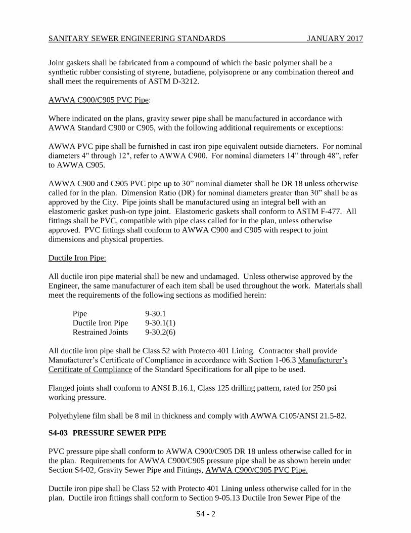
SANITARY SEWER ENGINEERING STANDARDS JANUARY 2017
S4 - 2
Joint gaskets shall be fabricated from a compound of which the basic polymer shall be a
synthetic rubber consisting of styrene, butadiene, polyisoprene or any combination thereof and
shall meet the requirements of ASTM D-3212.
AWWA C900/C905 PVC Pipe:
Where indicated on the plans, gravity sewer pipe shall be manufactured in accordance with
AWWA Standard C900 or C905, with the following additional requirements or exceptions:
AWWA PVC pipe shall be furnished in cast iron pipe equivalent outside diameters. For nominal
diameters 4" through 12", refer to AWWA C900. For nominal diameters 14” through 48”, refer
to AWWA C905.
AWWA C900 and C905 PVC pipe up to 30” nominal diameter shall be DR 18 unless otherwise
called for in the plan. Dimension Ratio (DR) for nominal diameters greater than 30” shall be as
approved by the City. Pipe joints shall be manufactured using an integral bell with an
elastomeric gasket push-on type joint. Elastomeric gaskets shall conform to ASTM F-477. All
fittings shall be PVC, compatible with pipe class called for in the plan, unless otherwise
approved. PVC fittings shall conform to AWWA C900 and C905 with respect to joint
dimensions and physical properties.
Ductile Iron Pipe:
All ductile iron pipe material shall be new and undamaged. Unless otherwise approved by the
Engineer, the same manufacturer of each item shall be used throughout the work. Materials shall
meet the requirements of the following sections as modified herein:
Pipe 9-30.1
Ductile Iron Pipe 9-30.1(1)
Restrained Joints 9-30.2(6)
All ductile iron pipe shall be Class 52 with Protecto 401 Lining. Contractor shall provide
Manufacturer’s Certificate of Compliance in accordance with Section 1-06.3 Manufacturer’s
Certificate of Compliance of the Standard Specifications for all pipe to be used.
Flanged joints shall conform to ANSI B.16.1, Class 125 drilling pattern, rated for 250 psi
working pressure.
Polyethylene film shall be 8 mil in thickness and comply with AWWA C105/ANSI 21.5-82.
S4-03 PRESSURE SEWER PIPE
PVC pressure pipe shall conform to AWWA C900/C905 DR 18 unless otherwise called for in
the plan. Requirements for AWWA C900/C905 pressure pipe shall be as shown herein under
Section S4-02, Gravity Sewer Pipe and Fittings, AWWA C900/C905 PVC Pipe.
Ductile iron pipe shall be Class 52 with Protecto 401 Lining unless otherwise called for in the
plan. Ductile iron fittings shall conform to Section 9-05.13 Ductile Iron Sewer Pipe of the
SANITARY SEWER ENGINEERING STANDARDS JANUARY 2017
S4 - 3
Standard Specifications and ANSI Standards A21.10 and A21.11.
HDPE pipe shall be in accordance with ASTM F 714 and ASTM D3035-83. All pipe and
fittings shall be SDR 26 at a minimum.
S4-04 HDPE PIPE
Butt-fused welded HDPE pipe shall be considered by the City on a case-by-case basis under the
following conditions:
A. HDPE pipe is only used for transmission lines with no laterals.
B. HDPE pipe is used for buried piping only.
C. The use of HDPE pipe is reserved for situations in which conventional PVC
sewer pipe may not be appropriate: non-linear alignments, low-head siphons,
steep slopes in sensitive/protected areas, etc.
S4-05 ABS PIPE & FITTINGS
ABS (acrylonitrile-butadiene-styrenecomposite) pipe shall conform with the provisions of
ASTM D-2680, Type S.C. joints (solvent welded).
ABS composite pipe is not allowed in the right-of-way or in the easements dedicated to the City.
S4-06 FITTINGS
All fittings shall be of the same material as the pipe unless otherwise specified. For side sewers,
a tee shall be installed in pipelines 8” or larger (or 6” main lines running between manholes) with
6” inside diameter side outlet. On 6” side sewer lines, wyes shall be used.
For side sewer connections to existing sewer lines, a flexible metallic side sewer saddle shall be
used for hole-cuts. If any other type of fitting is required, the type and make shall be specified
on the plans.
S4-07 CAPS AND PLUGS
All open ends shall be sealed with a plug or cap and gasket material approved by the Utility. The
plug or cap shall be able to withstand all test pressures without leakage.
S4-08 BOLTS IN PIPING
Bolts shall be malleable iron, Cor-ten, or stainless steel.
Bolts and nuts for flanged pipe and fittings shall conform in size and length with ANSI/AWWA
C115/A21.15. T-bolts shall be malleable iron, or Cor-ten in accordance with ANSI/AWWA
C111/A21.11. Stainless steel bolts shall meet the requirements of A193 Grade B8M. Shackle
rods, nuts and washers shall be All Thread stainless steel 316SS.
SANITARY SEWER ENGINEERING STANDARDS JANUARY 2017
S4 - 4
Stainless steel nuts, bolts and washers shall be type 316SS.
S4-09 FLANGE GASKETS
Gasket Material shall be neoprene, Buna N. chlorinated butyl, or cloth inserted rubber.
S4-10 GATE VALVE
The minimum requirements for all gate valves, 2" to 12", shall, in design, material and
workmanship, conform to the Standards of AWWA C-509.
Buried gate valves shall be iron body, bronze mounted, resilient seat, and non-rising stem,
suitable for installation with the type and class of pipe being installed. Ends to be as specified.
Operating stems equipped with standard two (2) inch operation nut, and O-ring stem seals.
Valves not buried shall be as specified.
S4-11 VALVE BOX
Valve Box shall be cast iron, two-piece, 8" or 18" slip type top section with flange located within
3" of top with 24" bottom section (and extension, if required), equal to RICH-Seattle Type.
Valve box lid shall be cast iron, 3 " deep, with recessed lifting handle, and the word “SEWER”
or “SS” cast into it.
Valve box paving risers shall be cast iron suitable for H-20 traffic loading. The riser shall have
four lugs or a flange around the perimeter, and be sized to fit into a RICH-Seattle Type valve box
top.
Valve box adjusting sleeves (for use in unimproved areas) shall be cast iron, 12" long.
All castings shall be coated with asphaltic varnish.
S4-12 VALVE OPERATING NUT EXTENSION
Use where valves are installed more than 3' below finished grade. Extensions are to be a
minimum of 1' with only one extension per valve. See Water Standard Detail.
S4-13 MANHOLES
Manholes shall be precast concrete sections with a confined O-ring rubber gasket joints per
ASTM C-478 and ASTM C-443 with a precast base.
Galvanized safety steps shall be fabricated of minimum size No. 8 (1") deformed bar conforming
to ASTM A-615, intermediate or standard grade hot-bent and galvanized after bending.
Galvanizing shall conform to ASTM A-123.
Polypropylene safety steps shall be constructed from polypropylene, conforming to ASTM
SANITARY SEWER ENGINEERING STANDARDS JANUARY 2017
S4 - 5
D-4101, injection molded around a 1/2" diameter grade 60 steel reinforcing bar conforming to
ASTM A-615. The polypropylene step shall be either cast-in-place or driven into pre-formed
holes in the manhole wall. The step shall be capable of resisting pullout forces exceeding 1,500
pounds.
Steps and ladders dimensions shall conform to the Standard Detail S-13. Steps shall project
uniformly from the inside wall of the manhole. Steps shall be installed to form a continuous
vertical ladder with rungs equally spaced at 12" centers. Steps in precast base may be cast in
place safety steps, or prefabricated galvanized hanging ladder per Standard Detail S-13
fabricated with #8 (1") reinforcing bar and #7 smooth steel bar conforming with ASTM A-615,
Grade 40, galvanizing conforming with ASTM A-123.
Concrete adjustment rings shall conform to the ASTM C-32, Grade MA.
Mortar used shall be composed of one part cement to two parts of plaster sand.
Outside drop structures shall be constructed with AWWA C-900 pipe and fittings, DR 18. Inside
drop structures shall be constructed of ASTM D-3034, SDR 35 PVC pipe and fittings.
As an alternate to steel reinforcement, 48” diameter x 3’ high eccentric or concentric cone
sections may be reinforced with synthetic fiber. The synthetic fiber shall meet the requirement
of ASTM C-1116 Type III. The synthetic fiber shall be added at a rate of 0.75 pounds per cubic
yard of concrete and shall be thoroughly mixed with the concrete before placement in the forms.
The synthetic fibers shall be a minimum of 0.75” and a maximum of 2” in length. A minimum
of two (2) hoops of W2 wire shall be placed in the 48” end of each cone. No steel is required in
the remainder of the cone.
S4-14 MANHOLE LINING
In instances where high velocity flows entering the manhole can potentially erode the interior
wall(s), the City may require an epoxy based structural lining system be installed in the new or
existing manhole. This is applicable in areas with steep pipe slopes, and in the Downtown
(DNTN) area where high rise residential buildings discharge directly into one manhole. The
epoxy based liner shall be installed per the manufacturer’s specifications. Approved epoxy
lining systems shall be Raven 404, Neopoxy, or an approved equal.
S4-15 MANHOLE RING & COVER
Ductile iron and cast iron rings and covers shall conform to the Standard Details and Section 9-
05.15 of the Standard Specifications, as modified herein.
Casting shall conform to the requirements of ASTM A-536, Grade 80-55-06 for ductile iron and
ASTM A-48, Class 30 for cast iron, and shall be free of porosity, shrinkage cavities, cold shuts,
or cracks, or any surface defects which would impair serviceability. Repair of defects by
welding or by the use of “smooth-on” or similar material will not be permitted.
Manhole rings and covers shall be machine-finished or ground-on seating surfaces so as to assure
non-rocking fit in any position and interchangeability. At the request of the City, there shall be
SANITARY SEWER ENGINEERING STANDARDS JANUARY 2017
S4 - 6
made available at the foundry standard rings and standard covers for use by inspectors in testing
fit and seating.
New and replacement sanitary sewage systems shall be designed to minimize or eliminate
infiltration of flood waters into the systems and discharges from the systems into flood waters.
For all manholes located in the curb and gutter line, flood plains, or flood areas in easements, the
installation of a locking gasketed ring and cover will be required. Manhole covers shall have a
standard pick hole for removal.
When bolt-locking covers are required, the locking bolts shall be 5/8" - 11 NC stainless steel
type 316SS socket (allen) head bolts, 2” long.
At the request of the Engineer, there shall be made available at the foundry a testing device
suitable for proving the capacity of the assembly to resist an uplift pressure on the lid equal to 20
feet of head.
S4-16 CONCRETE BEDDING & BLOCKING
Bedding, blocking, or encasement concrete shall be mixed from materials acceptable to the
Engineer and shall have a 30-day compressive strength of not less than 2,500 psi. The mix shall
contain five (5) sacks of cement per cubic yard and shall be of such consistency that the slump is
between 1” and 5”. All concrete shall be mechanically mixed.
S4-17 OIL/WATER SEPARATOR
Oil/Water separator vaults shall be of precast concrete construction.
Cement concrete shall have a minimum 28-day compressive strength of 4500 pounds per square
inch.
Deformed bars for steel reinforcement shall be in accordance with ASTM A-615, grade 60.
Welded-wire fabric reinforcement shall be in accordance with ASTM A-185, grade 65. All
interior piping shall be PVC sized to match side sewer line size. Baffles and weir shall be
1/2-inch thick steel plates galvanized in accordance with ASTM A-123. Vault cover shall
include one (1) 24 inch square diamond plate access door and two (2) 12 inch square diamond
plate inspection covers centered over outlet tee and inlet. Cover shall be designed for AASHTO
H-20 load. See the Standard Details for vault sizes and miscellaneous details.
S4-18 GREASE INTERCEPTOR
Grease Interceptor Vaults shall be of precast concrete construction. Cement concrete shall have
a minimum 28-day compressive strength of 4500 pounds per square inch.
Deformed bars for steel reinforcement shall be in accordance with ASTM A-615, grade 60.
Welded-wire fabric reinforcement shall be in accordance with ASTM A-185, grade 65. All
interior piping shall be PVC sized to match side sewer line size.
Interior baffle shall be precast reinforced concrete, 4” thick. Concrete baffle shall be secured in
SANITARY SEWER ENGINEERING STANDARDS JANUARY 2017
S4 - 7
place by slotted vault walls or with stainless steel angles as shown in the Standard Detail.
Vault cover shall include 24” diameter bolt-locking manhole covers and frames located over
inspection tees. Manhole covers shall not allow passage of air or gases. Vault cover shall be
designed for AASHTO H-20 load with 30% impact factor. See the Standard Details for vault
sizes and miscellaneous details.
S4-19 LIDS, HATCHES AND COVERS – SLIP RESISTANCE
Metal lids, hatches and access covers shall be constructed with a non-slip treatment having a
coefficient of friction between 0.6 and 1.0 wet, as determined by ASTM C1028-89. Lids,
hatches and access covers located on slopes of 4% or greater shall have a coefficient of friction
between 0.8 and 1.0 wet, as determined by ASTM C1028-89. Prior to installation, the
Contractor shall supply the Engineer with a shop drawing of the appurtenance specifying a
coefficient of friction meeting or exceeding the above requirement.
S4-20 COMMERCIAL CLEAN-OUT WITH TEST SAMPLING TEE
Commercial clean-out and sampling tee shall consist of PVC pipe and fittings configured as
shown in the Standard Detail. Clean-out access shall consist of a cast-iron material imbedded in
3000 psi concrete as shown in the Standard Detail. Sampling tee enclosure shall be a meter box
as specified in the Standard Detail.
S4-21 BACKWATER VALVE
Backwater check valve installed on 4” to 8” diameter side sewers shall be rubber flapper swing
type check valve. Flapper shall be constructed from steel reinforced rubber with 45-durometer
standard rubber hardness. Valve seat shall be at 45° angle to direction of flow. Flow area
through valve shall equal full pipe area. Valve body shall be cast iron with flanged ends and
bolted over to allow removal of flapper without removing valve from line.
Backwater valve shall be housed in 48” diameter precast concrete valve chamber with a
48-inch by 24-inch concentric reducing cone, or plastic meter boxes, depending on depth.
24-inch frame and cover shall be marked “sewer”. See Standard Detail.
S4-22 MECHANICAL SEWER PLUG FOR LAKE LINE CLEAN-OUT
Mechanical sewer plugs for lake line side sewer clean-outs located below the hydraulic gradient
shall be designed to withstand uplift pressure from force main.
Mechanical plug shall consist of aluminum body with double tapered rubber ring. Plug shall be
engaged by mechanical compression of rubber ring against pipe walls.
Plug shall include integral handle allowing manual operation of the plug. Rubber ring shall be
engaged or disengaged by twisting handle.
S4-23 BARRIER FENCE
SANITARY SEWER ENGINEERING STANDARDS JANUARY 2017
S4 - 8
Barrier Mesh shall be manufactured from Low Density Polyethylene, stabilized against U.V.
degradation, and with a special selection of pigments to ensure optimum visual performance
under harsh weather conditions.
Barrier Mesh shall be corrosion-free and resistant to salt water and most chemicals.
Barrier Mesh shall present a visual target area of approximately 0.5 square meter per square
meter of mesh.
S4-24 BEDDING AND BACKFILL
S4-24.1 Pipe Bedding Materials
For Ductile Iron Pipe (DIP), bedding material shall be in accordance with Section 9-
03.12(3) Gravel Backfill for Pipe Zone Bedding of the Standard Specifications.
For convenience, crushed rock bedding conforming to crushed surfacing top course
material of Section 9-03.9(3) Crushed Surfacing of the Standard Specifications may also
be used as bedding material for pipe.
In unpaved areas, the Contractor may request to use excavated material used as pipe
bedding where it has been determined by the Engineer as suitable meeting the
requirements of Section 9-03.12(3) Gravel Backfill for Pipe Zone Bedding of the
Standard Specifications, and proper compaction levels can be achieved.
For Polyvinyl Chloride (PVC) pipe, Corrugated Polyethylene (CPE) pipe, and other
thermoplastic pipe, bedding material shall be imported material conforming to crushed
surfacing top course material of Section 9-03.9(3) Crushed Surfacing of the Standard
Specifications.
For ductile iron sewer pipe, the Contractor may request to use excavated material as pipe
bedding where it has been determined by the Engineer as suitable material meeting the
requirements of Section 9-03.12(3) Gravel Backfill for Pipe Zone Bedding of the
Standard Specifications and proper compaction levels can be achieved.
S4-24.2 Trench Backfill Materials
For transverse trenches (perpendicular to the roadway centerline) in paved areas, crushed
rock backfill conforming to Section 9-03.9(3) Crushed Surfacing of the Standard
Specifications shall be used as trench backfill for pipe.
For longitudinal trenches (trenches parallel to the centerline of the roadway) in paved
areas, backfill material (4 feet and deeper below finished grade) shall conform to Section
9-03.14(1) Gravel Borrow of the Standard Specifications. The Contractor may request to
use excavated material as trench backfill and must demonstrate to the Engineer that the
suitable excavated material conforms to Section 9-03.14(1) Gravel Borrow of the
Standard Specifications and proper compaction levels can be achieved. Admixtures
and/or additives may not be used to modify the moisture content in order to meet
SANITARY SEWER ENGINEERING STANDARDS JANUARY 2017
S4 - 9
compaction specifications.
The top 4 feet of longitudinal trenches shall be backfilled with crushed rock conforming
to Section 9-03.9(3) Crushed Surfacing of the Standard Specifications.
In unpaved areas, trench backfill material shall conform to Section 9-03.14(1) Gravel
Borrow of the Standard Specifications. The Contractor may request to use excavated
material as trench backfill when it has been determined by the Engineer to be suitable and
conforms to Section 9-03.14(1) Gravel Borrow of the Standard Specifications and proper
compaction levels can be achieved.
S4-24.3 Structure Backfill Materials
In paved areas, backfill material (4 feet and deeper below finished grade) shall conform
to Section 9-03.14(1) Gravel Borrow of the Standard Specifications. The Contractor may
request to use excavated material as trench backfill when it has been determined by the
Engineer to be suitable and conforms to Section 9-03.14(1) Gravel Borrow of the
Standard Specifications and proper compaction levels can be achieved.
The top 4 feet around structures shall be backfilled with crushed rock conforming to
Section 9-03.9(3) Crushed Surfacing - Top Course of the Standard Specifications.
In unpaved areas, structure backfill material shall conform to Section 9-03.14(1) Gravel
Borrow of the Standard Specifications. The Contractor may request to use excavated
material as structure backfill when it has been determined by the Engineer to be suitable
and conforms to Section 9-03.14(1) Gravel Borrow of the Standard Specifications and
proper compaction levels can be achieved.
S4-24.4 Foundation Gravel Materials
Foundation gravel for structures shall consist of one of the following aggregates as set
forth in the Standard Specifications:
Ballast 9-03.9(1)
Shoulder Ballast 9-03.9(2)
Gravel Backfill for Foundations (Class A or B) 9-03.12(1)
Foundation Material Class A and Class B 9-03.17
S4-24.5 Controlled Density Fill Materials
Controlled density fill (CDF, aka flowable fill) shall be a mixture of Portland Cement,
admixture (optional), Fly Ash, aggregates and water. It shall be proportioned to provide a
grouty, non-segregating, free flowing, self-consolidating and excavatable material that will
result in a non-settling fill which has measurable unconfined compressive strength.
Materials testing shall be with unconfined compressive test cylinders. Test data may be
either laboratory trial batch test data or field test data.
SANITARY SEWER ENGINEERING STANDARDS JANUARY 2017
S4 - 10
Alternate mix designs may be required at the Engineer's discretion.
The unconfined compressive strength at 28 days shall be a minimum of 50 psi and a
maximum of 100 psi. Material shall be a sand/grout slurry proportioned to be hand-
excavatable after long term strength gain.
Materials shall meet the requirements of the following sections of the Standard
Specifications:
Portland Cement 9-01
Fine Aggregate for Portland Cement Concrete 9-03.1(2)
Admixture for Concrete 9-23.6
Fly Ash 9-23.9
Water 9-25
Controlled density fill shall meet the following requirements:
Controlled Density Fill
Ingredients Amount per Cu. Yd.
Portland Cement 50 lb.
Aggregates Class 1 or 2 3300 lb.
Air Entrainment Admixture Per Manufacturer’s recommendations
Fly Ash Class F 300 lb.
Water 300 lb. (maximum)
The material consistency shall be flowable (approx. slump 3-10”). If requested by the
Contractor, the proportions may be adjusted with the approval of the Engineer.
S4-25 STEEL CASING
Steel casing shall be black steel pipe conforming to ASTM A-53. Before installing, coat casing
exterior with shop-applied anticorrosive coating conforming to AWWA C210. Minimum
coating thickness shall be 16 mils dry film thickness (DFT); however, thickness shall not exceed
manufacturer’s recommended thickness. Coating type shall be a polyamide epoxy-coal tar equal
to Tnemec Hi-Build Tneme-Tar, Series 46H-413.
Casing wall thickness shall be 0.250” for casings 24” or less in diameter and 0.375” for casings
over 24” in diameter.
Carrier pipe for sewage shall be PVC (SDR 35).

SANITARY SEWER ENGINEERING STANDARDS JANUARY 2017
S4 - 11
S4-26 CASING SPACER
Casing spacers shall be installed in casings over 10 feet long. Where casing spacers are not used,
the carrier pipe shall be more than 10 feet in length (no pipe joints inside casing).
Casing spacer shell shall be manufactured in two pieces from heavy gauge T-304 stainless steel
or 14 gauge hot rolled pickled steel joined with ribbed flanges. The shell shall be lined with a
PVC liner 0.090” thick with 85-90 durometer.
Carbon steel casing spacer shell and risers shall be coated with a heat fused Polyvinyl chloride
coating, or hot-dip galvanized. Polyvinyl Chloride Coating Specifications:
Durometer - Shore A2 (10 Sec.) (ASTM D-1706-61T) - 80
Max. operating temperature (constant) - 150˚(65˚C)
Electrical properties (ASTM D-149-61)
(short time .010") - 1380 V/Mil
Resistance:
Salt spray (ASTM B-117) - Excellent
Acids - Good
Alkalies - Good
All nuts and bolts shall be 18-8 stainless steel.
Runners shall be supported by risers made from heavy gauge T-304 stainless steel or 12 gauge
hot rolled pickled steel. Runners shall be ultra high molecular weight polymer with high
resistance to abrasion and sliding wear.
TYPICAL DATA
PROPERTY ASTM METHOD UNITS VALUE
Specific Gravity D-792 gm/cc .934
Tensile Strength (Break) D-638 PSI 3500
Elongation (Break) D-638 % 380
Izod Impact D-256 Ft. Lbs./in. of notch No break
Hardness D-2240 Shore D 67
Coefficient of Friction D-1894 - 0.11 - 0.13
Heat Distortion Temp.
66 PSI D-648 C 88
Coefficient of Thermal D-696 F-1 5.5 x 10⁻⁵
ABRASION CHARACTERISTICS
Taber Abrasion D-1044 Mg/loss N
Sand Slurry * 7
* Sand slurry condition - 7 hours in one part sand/ one part water slurry at 1725 RPM.

SANITARY SEWER ENGINEERING STANDARDS JANUARY 2017
S4 - 12
Carbon steel - 100, Hifax - 15. The lower the value, the more resistant to abrasion.
Casing spacers shall be "center positioning" type. Height of risers and runners combined shall be
sufficient to keep the carrier pipe bell, couplings, or fittings at least 0.75" from the casing pipe
wall at all times and provide at least 1" clearance between runners and top of casing wall, to
prevent jamming during installation.
S4-27 NEOPRENE FOAM PAD
Where approved by the City, a neoprene foam pad may be used for cushion between adjacent
pipes which are not meeting minimum vertical clearance requirements. The approved material is
the Dow Plastics Ethafoamtm 220, or an approved equal meeting the same ASTM requirements.
END OF CHAPTER S4
SANITARY SEWER ENGINEERING STANDARDS JANUARY 2017
CHAPTER S5 - SEWER METHODS OF CONSTRUCTION
TABLE OF CONTENTS
S5-01 GENERAL CONSTRUCTION REQUIREMENTS ............................. S5 - 1
S5-02 GRADE ESTABLISHMENT ................................................................ S5 - 1
S5-03 MANHOLE EXCAVATION ................................................................ S5 - 2
S5-04 PIPE LAYING ....................................................................................... S5 - 2
S5-05 ALIGNMENT TOLERANCE ............................................................... S5 - 3
S5-06 JOINTS .................................................................................................. S5 - 3
S5-07 PRESSURE SEWER MAINS AND VALVES ..................................... S5 - 3
S5-08 SIDE SEWERS ...................................................................................... S5 - 4
S5-09 MANHOLES ......................................................................................... S5 - 5
S5-10 CONNECTION TO EXISTING MANHOLE ....................................... S5 - 6
S5-11 CLEANING & FLUSHING .................................................................. S5 - 7
S5-12 TESTING OF GRAVITY SEWERS ..................................................... S5 - 7
S5-13 CLOSED CIRCUIT TELEVISION (CCTV) INSPECTION .............. S5 - 10
S5-14 TESTING OF PRESSURE SEWER MAINS...................................... S5 - 10
S5-15 VACUUM TESTING OF PRECAST CONCRETE MANHOLES ...... S5-10
S5-16 OIL/WATER SEPARATOR ............................................................... S5 - 12
S5-17 GREASE INTERCEPTOR .................................................................. S5 - 12
S5-18 COMMERCIAL CLEAN-OUT WITH TEST SAMPLING TEE ....... S5 - 13
S5-19 BACKWATER VALVE ...................................................................... S5 - 13
S5-20 LAKE LINE CLEAN-OUT ................................................................. S5 – 14

SANITARY SEWER ENGINEERING STANDARDS JANUARY 2017
S5-21 PRECONSTRUCTION PHOTOS FOR CITY CONTRACTS ........... S5 - 14
S5-22 UNDERGROUND UTILITIES ........................................................... S5 - 14
S5-23 CONSTRUCTION ON EASEMENTS ............................................... S5 - 15
S5-24 DUST CONTROL ............................................................................... S5 - 15
S5-25 BARRIER FENCE............................................................................... S5 - 15
S5-26 TRENCH EXCAVATION .................................................................. S5 - 15
S5-27 TRENCHLESS CONSTRUCTION .................................................... S5 - 16
S5-28 SHEETING & SHORING ................................................................... S5 - 17
S5-29 TRENCH DEWATERING .................................................................. S5 - 17
S5-30 BEDDING, BACKFILL AND COMPACTION ................................. S5 - 17
S5-31 ADJUST EXISTING STRUCTURE TO GRADE .............................. S5 - 20
S5-32 ABANDONING FACILITIES ............................................................ S5 - 21
S5-33 LAWN REMOVAL AND REPLACEMENT ..................................... S5 - 21
S5-34 BORING UNDER ROOTS ................................................................. S5 - 22
S5-35 HIGHWAY AND RAILWAY CROSSINGS ..................................... S5 - 22
S5-36 BORING AND JACKING STEEL CASING...................................... S5 - 22
S5-37 WORKING WITH ASBESTOS CEMENT PIPE ............................... S5 - 23
S5-38 ASBESTOS CEMENT WATER MAIN CROSSINGS ...................... S5 - 23
S5-39 CLEARANCES/OTHER UTILITIES ................................................. S5 - 23
SANITARY SEWER ENGINEERING STANDARDS JANUARY 2017
S5 - 1
CHAPTER S5 - SEWER METHODS OF CONSTRUCTION
S5-01 GENERAL CONSTRUCTION REQUIREMENTS
The improvements shall be constructed as shown on the plans and in accordance with these
Standards, Standard Details, and Standard Specifications. Manufacturer’s equipment shall be
installed in compliance with specifications of the manufacturer, except where a higher quality of
workmanship is required by the plans and specifications. All materials and work shall be in
strict accordance with any applicable regulations of the State, County and local authorities. The
Contractor shall arrange for such inspection by these agencies as may be required and shall
submit evidence of their approval, if requested by the Engineer.
S5-01.1 Alignment & Staking
All work done under a Project shall be to the lines shown on the plans, or to approved
revisions.
S5-01.2 Inspections & Tests
A. The Engineer shall, at all times, have access to the work for the purpose of
inspecting and testing, and the Contractor shall provide proper facilities for such
access and such inspection and testing.
B. If any work is covered up without approval or consent of the Engineer, it must, if
required by the Engineer, be uncovered for inspection.
C. Before a performance test is to be observed by the Engineer, the Contractor shall
make whatever preliminary tests are necessary to assure that the material and/or
equipment are in accordance with the plans and specifications.
D. Written notice of deficiencies, adequately describing the same, shall be given to
the Contractor upon completion of each inspection and the Contractor shall
correct such deficiencies within seven days of the notice and before final
inspection will be made by the Engineer, unless otherwise approved.
S5-02 GRADE ESTABLISHMENT
Sewer grades shall be established by means of laser beam, grade boards, lines, poles, plumb bobs
or other means approved by the Engineer. The grades shall be checked at periodic intervals as
directed by the engineer.
If the contractor chooses to use the conventional use of grade boards, lines, poles and plumb
bobs, the grades shall be carried by means of taut grade wire supported on firmly set batter
boards at intervals of not more than 30 feet. No fewer than 4 batter boards set from grade hubs
shall be used at one time.
Grade shall be constantly checked and, in the event that batter boards do not line up, work shall
be stopped until the situation is corrected.

SANITARY SEWER ENGINEERING STANDARDS JANUARY 2017
S5 - 2
The distance from the grade wire to the invert of the sewer shall be measured by a pole, which
shall be a straight-grained, planed pole, fitted with an iron shoe extending at least 8 inches from
the pole at the lower end and clearly marked at intervals of 1 foot. A plumb bob shall be used to
check the line of the pipe. Both grade and line shall be checked for each length of pipe laid,
except at tunnels or through jacked casings where adequate methods shall be used to carry
forward the line and grade.
If the Contractor chooses to use a laser beam, the equipment and methods shall meet the
approval of the Engineer. Laser beam alignment and grade shall, at a minimum, be verified at a
point 50 feet from the laser by use of a grade board.
The Contractor shall replace all monuments, right-of-way markers, property stakes, etc., that are
removed or disturbed, to the satisfaction of the Engineer.
S5-03 MANHOLE EXCAVATION
Excavation for precast manholes shall be sufficient to provide a minimum of 12 inches between
the manhole and the side of the excavation. The excavation shall be kept free from water until
jointing has been completed. Surface water shall be diverted so as not to enter the excavation.
The contractor shall maintain sufficient pumping equipment on the job to insure that these
provisions are carried out.
S5-04 PIPE LAYING
Pipe laying shall be in accordance with the following:
Each pipe shall be laid with bells upgrade with the invert of the pipe to the alignment and grade
shown on the plans. Care shall be exercised to insure close concentric joints and a smooth
invert. Open ends of pipe and fittings shall be temporarily blocked and covered when laying is
not in progress.
Water shall not be allowed in the trench during the pipe laying, joint making, and as long
thereafter as is necessary, in the judgment of the Engineer, for the type of joint being used.
Existing sewage flow shall be diverted away from the segment being worked on by method
approved by the Engineer.
Adjustment to the line and grade shall be done by scraping away or filling in and tamping
material under the body of the pipe. Adjustment to the line and grade by wedging and blocking
shall not be permitted.
The pipe shall be lowered into the trench by means of ropes, tripod, crane or any other suitable
means. The pipe shall not be dropped or handled roughly. The pipe shall be checked for cracks
and defects prior to use and any defective pipe rejected.
Tees, wyes, and standing services shall be installed as shown on the Standard Details and at such
locations as are shown on the plans or as otherwise directed by the Engineer. These items shall
SANITARY SEWER ENGINEERING STANDARDS JANUARY 2017
S5 - 3
not be covered until the Engineer has recorded their exact location.
Pipe laying shall start from the lowest point unless otherwise approved by the Engineer.
Slip lining shall be performed as per recommended procedure by manufacturer, as per details and
as approved by the Engineer.
Pipe shall not be located below soil nails. If the pipe is located above a soil nail, a minimum of
5’ clearance is required.
S5-05 ALIGNMENT TOLERANCE
The maximum tolerance from true line and grade shall be as follows:
Maximum deviation from established line and grade shall not be greater than one thirty-second
(1/32) inch per inch or pipe diameter and not to exceed one-half (1/2) inch.
No adverse grade in any pipe length will be permitted.
The difference in deviation from true line and grade between any two successive joints shall not
exceed 1/3 of the amounts specified above.
S5-06 JOINTS
Joint material shall be used in accordance with the recommendations of the manufacturer. Pipe
handling after the gasket has been affixed shall be carefully controlled to avoid bumping the
gasket and, thus knocking it out of position or contaminating it with dirt or other foreign
material. Any gasket so disturbed shall be removed, cleaned, re-lubricated and replaced.
Care shall be taken to properly align the pipe before joints are forced home. During insertion of
the tongue or spigot, the pipe shall be partially supported by hand, sling, or crane as required to
minimize lateral pressure on the gasket and to maintain concentricity until the gasket is properly
positioned. Pipe deflection and straightening shall be held to a very minimum once the joint is
home to prevent creep of the joint.
Sufficient pressure shall be applied in making the joint to assure that the joint is home as defined
in the standard installation instructions provided by the pipe manufacturer. Sufficient restraint
shall be applied to the line to assure the joints once home are held so by tamping fill material
under and alongside the pipe or otherwise. At the end of the day's work, the last pipe shall be
blocked in such a manner as may be required to prevent creep during down time.
S5-07 PRESSURE SEWER MAINS AND VALVES
S5-07.1 Pressure Main Installation
Pressure pipe as specified on the plans shall be installed as recommended by the pipe
manufacturer. Pressure sewer mains shall be laid so that no high point exists except at
the discharge manhole or an air release assembly.
SANITARY SEWER ENGINEERING STANDARDS JANUARY 2017
S5 - 4
S5-07.2 Valve Installation
Before installation, valves shall be cleaned of all foreign material. Such blocking as the
Engineer may deem necessary shall be provided. The valve and valve box shall be set
plumb with the valve box centered on the valve. Valves shall be opened and shut under
pressure to check operation without leakage. Where valve operating nut is more than
three feet below finished grade, a stem extension conforming to the Water Standard
Detail must be installed.
The top of the valve box base section shall be located a minimum of 6" and maximum of
9" below finished grade. A polyethylene sheet, 8-mils thick, shall be placed between the
top and base valve box sections to prevent metal to metal contact where the sections
overlap.
Valve box top sections shall be adjusted flush with the finished pavement and, in those
areas to be excavated for future roadway grades, enough adjustment shall be provided in
the valve box to allow the top of the box to be adjusted to the required grade.
S5-07.3 Valve Box Marker Installation
Concrete marker posts shall be painted with two coats Rust-Oleum No. 2766 Hi-Gloss
white paint. The marker shall be set on a line through the valve at right angles to the
centerline of the road. The marker shall generally be set on the property line unless the
Engineer decides another location is safer or more conspicuous. Distance to the valves
shall be neatly stenciled on the post with 2-inch numerals. Valve markers shall be
installed only in unimproved or unpaved areas.
S5-08 SIDE SEWERS
Side sewer locations as shown on the plan are approximate only.
All existing services shall be maintained during construction.
All existing side sewers shall be reconnected or replaced immediately after the trunk is laid.
When replacing an existing trunk, side sewers shall be reconnected after the main is tested, when
feasible.
Where applicable, all specifications contained herein for sewer materials and construction shall
be held to apply to side sewers. Invert of the side sewer at the end of the lateral shall be as
shown on the plan or as directed by the Engineer.
Ends of the side sewer laterals shall be marked with a 2 x 4 stake, 12 feet long, with one end
buried at the depth of the lateral-end invert and extending vertically out of the ground. The
portion of the stake above ground shall be painted white and marked with the word “SEWER”,
the depth from pipe invert to ground surface, and the distance from the main to the end of the
lateral. An 8-gauge wire shall attach the end of the capped lateral to the 2 x 4 stake, at or above
finished ground. See Standard Detail for side sewer laterals.
SANITARY SEWER ENGINEERING STANDARDS JANUARY 2017
S5 - 5
Slope of side sewers shall not exceed one hundred percent (100%) and shall not be less than two
percent (2%). All side sewers shall be capped.
Where change in slope is greater than two inches per foot, standard 1/8 bends shall be used.
S5-09 MANHOLES
Manholes shall be constructed as shown in the Standard Details for standard manholes and drop
manholes. Manholes shall be of precast reinforced concrete. Manhole ring and covers shall be
adjusted to the elevation required by the Engineer prior to final acceptance of the work.
The manhole base slab shall be placed on firm soil. If the foundation material is inadequate, the
Contractor shall use foundation gravel or bedding concrete under the normal base to support the
manhole.
Manholes in easements shall be constructed to provide a stable, level grade for a minimum radius
of 2.5 feet around the center of the access opening.
Manhole sections shall be placed and aligned so as to provide vertical sides and vertical
alignment of the ladder steps. The completed manhole shall be rigid, true to dimension, and be
watertight. Rough, uneven surfaces will not be permitted.
Where work is located in public right-of-way, not less than 10 inches (6 inch ring with 4 inches
of riser section) nor more than 24 inches (6 inch ring with 18 inches of riser section) shall be
provided between the top of the cone or slab and the top of the manhole frame.
The outside and inside of manhole adjusting bricks and the joints of any non-gasketed precast
concrete sections shall be thoroughly wetted and completely filled with mortar, plastered and
troweled smooth with 3/4 inch of mortar in order to attain a watertight surface. Mortar shall be
placed between each level of adjusting bricks, riser rings, top of cone section, and bottom of iron
ring.
All lift holes, if any, on precast items shall be completely filled with expanding mortar, smoothed
both inside and out, to insure water-tightness. All steel loops, if any, on precast section must be
removed and flush with the manhole wall. The laterals shall be covered with mortar and
smoothed. Rough, uneven surfaces will not be permitted.
Channels shall be made to conform accurately to the sewer grade and shall be brought together
smoothly with well-rounded junction, satisfactory to the Engineer. The channels shall be field
poured after the inlet and outlet pipes have been laid and firmly grouted into place at the proper
elevation. Allowances shall be made for a minimum of one-tenth foot (0.1') drop in elevation
across the manhole in the direction of flow. The maximum allowable drop in invert elevation
across the manhole in the direction of flow shall be 1.0 feet. Channel sides shall be carried up
vertically from the invert to the largest diameter of the various pipes. The concrete shelf shall be
warped evenly and sloped 1" per foot to drain. Rough, uneven surfaces will not be permitted.
Channels shall be constructed to allow the installation and use of a mechanical plug of the
appropriate size. Prefabricated manhole bases with glass fiber supported plastic or PVC hard
SANITARY SEWER ENGINEERING STANDARDS JANUARY 2017
S5 - 6
lined channels will be allowed at the Contractor's option.
All manholes located in unpaved areas shall include a concrete collar around the manhole
adjusting bricks per Standard Detail S-8; see MANHOLE GRADE ADJUSTMENT SECTION
DETAIL (UNPAVED AREAS). In unimproved easement areas, the manhole shall also have a
bolt-locking lid.
All rigid pipe entering or leaving the manhole shall be provided with flexible joints within
twelve inches (12") of the manhole structure and shall be placed on firmly compacted bedding.
Special care shall be taken to see that the openings through which pipes enter the structure are
completely and firmly filled with mortar from the outside to ensure water-tightness. All PVC
pipe connections to manholes shall be made with gasketed coupling as approved by the Utility.
S5-10 CONNECTION TO EXISTING MANHOLE
Connection to existing manhole shall be accomplished in such a manner that all existing services
are maintained, that no refuse, broken brick, concrete or other extraneous matter enter into the
existing sewer. The outfall shall be plugged or screened throughout the contractors operation at
the Engineer's option.
A circular opening shall be carefully core drilled in the manhole barrel on the proper alignment
so that the new sewer will be in line with the center of the manhole, and at the height which will
allow the new sewer to be placed at the proper grade. The opening shall be of such size as to
provide clearance of not less than one (1) or more than three (3) inches between the outside of
the pipe and the manhole wall. Pipe connections, channel forming, grouting of pipe and
backfilling shall be as specified previously for standard manholes.
No additional pipe shall be connected until final set of the grout has occurred. When additional
pipe is connected, care shall be taken to avoid shocks or other undue strains to the grouted pipe.
Any opening resulting from removal of existing pipe shall be filled with mortar to provide a
watertight seal, unless new pipe is to be reconnected to that opening.
When any new sewer is connected to an existing manhole with an inside drop structure, the
minimum angle between drop piping and existing access steps shall be 90º (1/4 of manhole
circumference), or 45º for 6" pipe. Where minimum clearance cannot be met, the cone section
shall be rotated and steps relocated to provide maximum possible clearance from drop tee and
pipe. Cut existing steps flush with manhole wall and cover laterals with mortar to provide a
smooth finish.
When any new sewer is connected to an existing manhole, the manhole shall be reconstructed to
conform to current standards.
Upward adjustments of old, existing manholes must be done with all new parts including cone
section so there is only one mismatched seam. The mismatched seam shall be reinforced with a
concrete collar poured around the seam, 6-inches to 12-inches above and below the seam line,
around the outside of the manhole, minimum 6-inches thick. The collar may also be sealed with
the Wrapid Sealtm (or equivalent) manhole encapsulation system.
SANITARY SEWER ENGINEERING STANDARDS JANUARY 2017
S5 - 7
In addition, where the new manhole barrel section key is not compatible with the existing barrel
section key, the new section key shall be broken off as shown in sanitary sewer Standard Detail
S-9, “Manhole Section Adjustment”.
S5-11 CLEANING & FLUSHING
Prior to pipe testing, all pipes shall be cleaned in the following manner:
The Contractor shall furnish an inflatable rubber ball of a size that will inflate to fit snugly into
the pipe to be tested. The ball may, at the option of the Contractor, be used without a tag line; or
a rope or cord may be fastened to the ball to enable the Contractor to know and control its
position at all times. The ball shall be placed in the last cleanout or manhole on the pipe to be
cleaned and water shall be introduced behind it. The ball shall pass through the pipe with only
the force of the water impelling it. All debris flushed out ahead of the ball shall be removed at
the first manhole where its presence is noted. In the event cemented or wedged debris or
damaged pipe stops the ball, the Contractor shall remove the obstruction.
S5-12 TESTING OF GRAVITY SEWERS
Method of testing gravity sewers shall be at the option of the Contractor unless otherwise
specified herein.
S5-12.1 Water Test
Tests for water tightness shall be made by the Contractor in the presence of the Engineer.
A test shall be made every section of the sewer, including the side sewers, after
completion of backfill. Where the groundwater table is so high as to preclude a proper
exfiltration test, an infiltration test may be used. The exfiltration test shall be made by
plugging the inlets of the lower manhole and filling the test section with water to a height
of six (6) feet above the crown of the sewer at the upper end of the sewer being tested.
In no case shall the static level be less than six (6) feet above the water table at the upper
end of the sewer being tested. Where the static pressure on the lower manhole would
exceed 20 feet, the Contractor may test the sewer between manholes in two or more
sections. The Contractor may provide for sectional testing by installing tees in the main
line. The tees shall be a type that permits plugging of both the upper and lower run of the
tee. The required static water head may be obtained by installing vertical lengths of pipe
in the tee or from the upper end of the sewer pipe being tested at shallow manholes.
The Contractor shall provide a groundwater observation well at each manhole for
determining the level of the groundwater during the test. The observation well shall
consist of one inch plastic pipe installed vertically adjacent to the manhole. The lower
end of the test well shall be placed in a one (1) cubic yard pocket of washed gravel and
shall be at the same elevation as the invert of the manhole. The upper end of the test well
shall be a maximum of two (2) feet below the finished grade elevation and shall be
plugged and exposed until completion of the test.
The time of exfiltration tests shall be a minimum of one (1) hour. The leakage during the

SANITARY SEWER ENGINEERING STANDARDS JANUARY 2017
S5 - 8
test shall not exceed the following allowances:
Allowable Leakage - Exfiltration or Infiltration
Allowable Leakage in gal\100 linear feet\hr. Head above Crown on Lower End of Test
Section.
Pipe 6 Ft. 8 Ft. 10 Ft. 12 Ft. 14 Ft. 16 Ft.
6 0.6 0.7 0.7 0.8 0.8 0.9
8 0.8 0.9 1.0 1.0 1.1 1.2
10 1.0 1.1 1.2 1.3 1.4 1.5
12 1.2 1.3 1.4 1.6 1.7 1.8
15 1.5 1.7 1.8 2.0 2.1 2.3
18 1.8 2.0 2.2 2.3 2.5 2.7
24 2.4 2.6 2.9 3.1 3.4 3.6
Repair by chemical grouting will not be allowed.
For static head above the basic eight feet at the crown of the sewer at the lower end of the
test section, the allowable leakage shown above shall be increased at a ratio of 5 percent
per foot increase.
Where the groundwater exceeds a height of six feet above the crown of the sewer at the
upper end of the test section, the section shall be tested by infiltration. The infiltration
test shall be conducted by placing a plug in the inlet sewer at the upper manhole and
inserting an approved measuring device in the inlet sewer at the lower manhole. Prior to
making measurements, care shall be taken to assure that the flow over or through the
measuring device is constant. A minimum of four measurements shall be made over a
period of one hour.
The acceptance water test shall be made after backfilling has been completed and
compacted, and ATB has been placed in areas to be paved.
S5-12.2 Air Testing
The Contractor may use a low-pressure air test at his option. The following procedures
shall be used on conducting the low-pressure air test. The Contractor shall furnish all
facilities and personnel for conducting the test under the observation of the Engineer.
The equipment and personnel shall be subject to the approval of the Engineer.
The Contractor may desire to make an air test prior to backfilling for his own purposes.
However, the acceptance air test shall be made after backfilling has been completed and

SANITARY SEWER ENGINEERING STANDARDS JANUARY 2017
S5 - 9
compacted, and ATB has been placed in areas to be paved.
All wyes, tees, or end of side sewer laterals shall be plugged with flexible joint caps, or
acceptable alternate, securely fastened to withstand the internal test pressures. Such
plugs or caps shall be readily removable and their removal shall provide a socket suitable
for making a flexible jointed lateral connection or extension. No double plugs shall be
allowed.
Immediately following the pipe cleaning, the pipe installation shall be tested with low-
pressure air. Air shall be slowly supplied to the plugged pipe installation until the
internal air pressure reaches 4.0 pounds per square inch greater than the average back
pressure of any groundwater that may submerge the pipe. At least two minutes shall be
allowed for temperature stabilization before proceeding further.
The requirements of this specification shall be considered satisfied if the time required in
seconds for the pressure to decrease from 3.5 to 2.5 pounds per square inch greater than
the average back pressure of any groundwater is at least as follows:
Seconds per
Size of Pipe Linear foot of Pipe
4 inch 0.11
6 inch 0.25
8 inch 0.46
10 inch 0.72
12 inch 1.04
15 inch 1.63
18 inch 2.35
21 inch 3.20
24 inch 4.18
The use of air pressure for testing sewer lines creates hazards that must be recognized.
The Contractor shall be certain that all plugs are securely blocked to prevent blowouts.
An air supply regulator shall be installed on the air supply line to the sewer that shall
permit a maximum of 10 psi in the line to be tested. All pressure shall be relieved from
the sewer section being tested prior to removal of test plugs.
S5-12.3 Deflection Test for Flexible Pipe
Sanitary sewers constructed of flexible pipe shall be deflection tested not less than 30
days after the trench backfill and compaction has been completed, and ATB has been
placed in areas to be paved.
The test shall be conducted by pulling a solid pointed mandrel with a circular cross
section with diameter equal to 95% of the inside pipe diameter through the completed
pipeline. Minimum length of circular portion shall be equal to the diameter of the pipe.
Pull shall be manual without mechanical assistance and the mandrel shall negotiate
deflected section freely.
SANITARY SEWER ENGINEERING STANDARDS JANUARY 2017
S5 - 10
Testing shall be conducted on a manhole to manhole basis and shall be done after the line
has been completely flushed out with water.
Contractor shall locate and repair any sections failing to pass the test and to retest the
section.
S5-13 CLOSED CIRCUIT TELEVISION (CCTV) INSPECTION
The Developer shall provide the Utility with a CCTV inspection of all sanitary sewers prior to
final project acceptance.
If defects are found or suspected during the one-year warranty period, the Utility may also
require that the Developer provide video inspection of any or all sanitary sewers before
expiration of the warranty.
The Contractor shall correct all deficiencies found during CCTV inspection.
The Contractor shall provide color CCTV equipment shall include television cameras, a
television monitor, cables, power sources, side-launch capable if necessary, and other equipment.
Focal distance shall be adjustable through a range from 6 inches to infinity. The CCTV
equipment shall include a distance measuring instrument (DMI) to measure the horizontal
distance traveled by the camera. The DMI readout shall appear continuously on the video
produced by the inspection and shall be accurate to less than 1 percent error over the length of
the section of pipeline being inspected. For storm or sanitary sewers, the length is measured from
the centerline of the manhole or catch basin to the centerline of the next manhole or catch basin.
The CCTV inspection system shall be performed utilizing one of the following video
camera systems:
Remote-focus stationary lens cameras;
Rotating lens cameras; or
Pan-and-tilt cameras.
The CCTV camera shall be mounted on a skid, floatable raft system, or transporter based on the
conditions of the pipeline to be televised. Telephones, radios, or other suitable means of
communication shall be utilized to ensure communication exists between members of the crew.
The contractor shall inspect the pipeline during optimum low-flow level conditions, as pre-
approved by the Utility Inspector. The contractor shall coordinate with the Utility Inspector prior
to video inspection. The television camera utilized shall be specifically designed and constructed
for sewer inspection. The camera shall be operative in 100 percent humidity conditions. Lighting
for the camera shall minimize reflective glare. Lighting and picture quality shall be suitable to
provide a clear, in-focus picture of the entire periphery of the pipeline for all conditions
encountered during the work. If the quality of the video is deemed to be unacceptable by the
Utility Inspector, the pipeline shall be re-televised at no cost to the City. The camera shall be
moved through the pipeline at a uniform rate, stopping when necessary to ensure proper
documentation of the pipeline condition, but in no case shall the television camera be pulled at a
speed greater than 30 feet per minute stopping when necessary to ensure proper documentation
of the pipe condition. The video shall be taken after installation, cleaning, and pressure test to
insure that no defects exist. The project will not be accepted until all defects have been repaired.

SANITARY SEWER ENGINEERING STANDARDS JANUARY 2017
S5 - 11
Data Requirements
The contractor will provide inspection/observation data in either PACP 4.4 or Granite
4.5.x database format. The contractor’s software for condition assessment video
recording must be submitted to and approved by the City.
Video Media Requirements
Video media must be recorded in color at a minimum of 640 x 480 resolution with a
minimum frame rate of 30 frames per second. The digital video compression will be
MPEG-1. The audio portion must be embedded in the video file (not a separate audio
file) and shall be sufficiently free from electrical interference and background noise to
provide complete and intelligible oral reporting.
Video File Name Requirements
Video file names should contain the pipe segment asset number being inspected, the date
and time of the video inspection, and optionally a sequence number if multiple
inspections are performed. (e.g. ‘123456-20151231.MPG’)
Photo Media Requirements
Photo media must be in JPEG format with a minimum of 16 bits per pixel color depth.
Photo resolution should be high enough to capture adequate details of an
observation/defect.
Photo File Name Requirements
Photo file names should contain the pipe segment asset number being inspected, the date
and time of the video inspection, the observation code, the distance from the inspection
starting point, and optionally a sequence number if multiple photos are taken for the same
observation. (e.g. ‘123456-20151231-DAGS-35FT.JPG’)
Media Delivery Requirements
Acceptable digital medium for the delivery of the data to City of Bellevue is USB hard
drives, USB flash drives or DVD data discs.
S5-14 TESTING OF PRESSURE SEWER MAINS
Prior to acceptance of the project, the pressure line shall be subjected to a hydrostatic pressure
test of 100 psi at the high point of the line. Any leaks or imperfections developing or occurring
under the test pressure shall be remedied by the Contractor before final acceptance of the project.
Leakage shall be measured by approved means. Test pressure shall be maintained while the
entire installation is inspected. The Contractor shall provide all necessary equipment and shall
perform all work connected with the tests. Insofar as is practical, test shall be made with pipe
joints and fittings exposed for inspection. Maximum allowable leakage shall be .05 gallons per
hour per inch of pipe diameter per 100 feet of pipe.
S5-15 VACUUM TESTING OF PRECAST MANHOLES
Prior to backfilling, each manhole shall be tested using the vacuum testing method specified in
ASTM C1244 to ensure that the manhole is watertight.
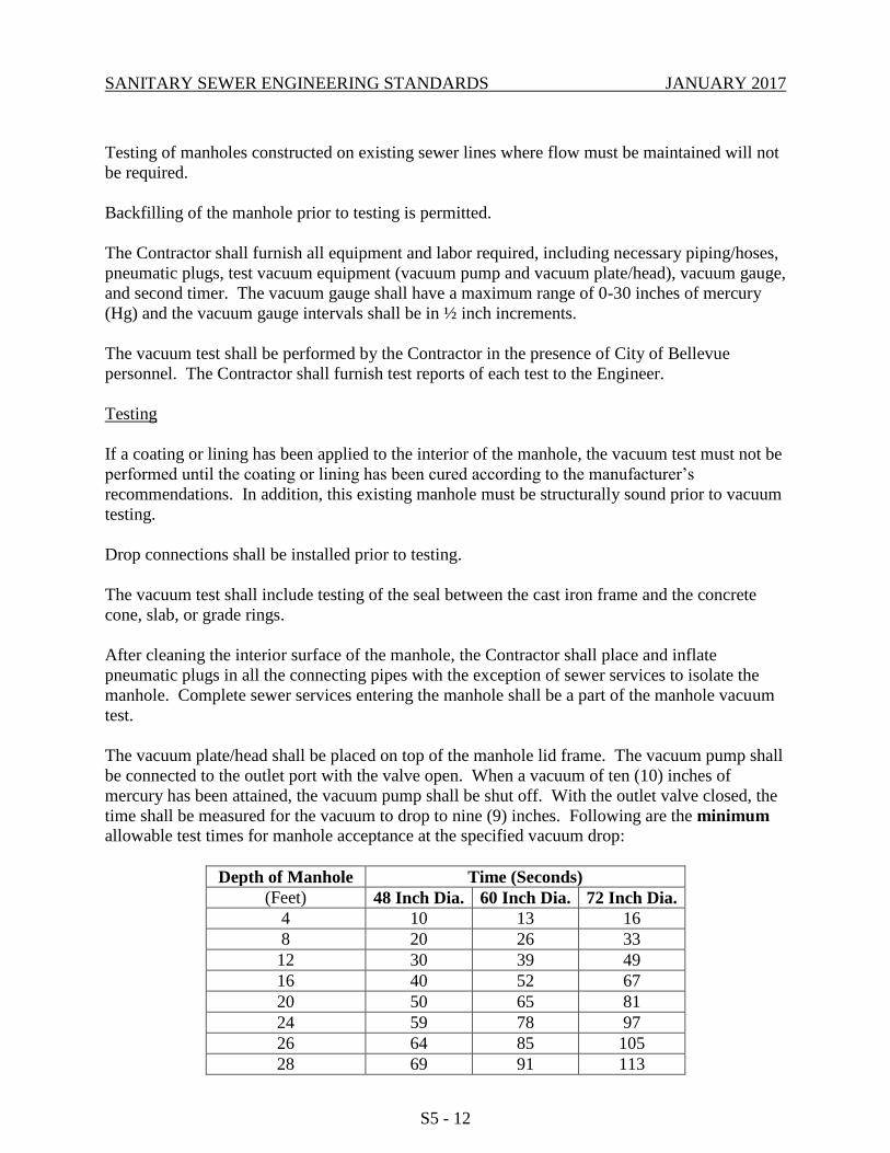
SANITARY SEWER ENGINEERING STANDARDS JANUARY 2017
S5 - 12
Testing of manholes constructed on existing sewer lines where flow must be maintained will not
be required.
Backfilling of the manhole prior to testing is permitted.
The Contractor shall furnish all equipment and labor required, including necessary piping/hoses,
pneumatic plugs, test vacuum equipment (vacuum pump and vacuum plate/head), vacuum gauge,
and second timer. The vacuum gauge shall have a maximum range of 0-30 inches of mercury
(Hg) and the vacuum gauge intervals shall be in ½ inch increments.
The vacuum test shall be performed by the Contractor in the presence of City of Bellevue
personnel. The Contractor shall furnish test reports of each test to the Engineer.
Testing
If a coating or lining has been applied to the interior of the manhole, the vacuum test must not be
performed until the coating or lining has been cured according to the manufacturer’s
recommendations. In addition, this existing manhole must be structurally sound prior to vacuum
testing.
Drop connections shall be installed prior to testing.
The vacuum test shall include testing of the seal between the cast iron frame and the concrete
cone, slab, or grade rings.
After cleaning the interior surface of the manhole, the Contractor shall place and inflate
pneumatic plugs in all the connecting pipes with the exception of sewer services to isolate the
manhole. Complete sewer services entering the manhole shall be a part of the manhole vacuum
test.
The vacuum plate/head shall be placed on top of the manhole lid frame. The vacuum pump shall
be connected to the outlet port with the valve open. When a vacuum of ten (10) inches of
mercury has been attained, the vacuum pump shall be shut off. With the outlet valve closed, the
time shall be measured for the vacuum to drop to nine (9) inches. Following are the minimum
allowable test times for manhole acceptance at the specified vacuum drop:
Depth of Manhole Time (Seconds)
(Feet) 48 Inch Dia. 60 Inch Dia. 72 Inch Dia.
4 10 13 16
8 20 26 33
12 30 39 49
16 40 52 67
20 50 65 81
24 59 78 97
26 64 85 105
28 69 91 113
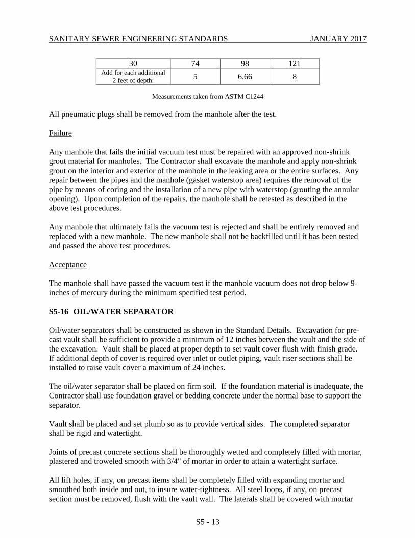
SANITARY SEWER ENGINEERING STANDARDS JANUARY 2017
S5 - 13
30 74 98 121 Add for each additional
2 feet of depth: 5 6.66 8
Measurements taken from ASTM C1244
All pneumatic plugs shall be removed from the manhole after the test.
Failure
Any manhole that fails the initial vacuum test must be repaired with an approved non-shrink
grout material for manholes. The Contractor shall excavate the manhole and apply non-shrink
grout on the interior and exterior of the manhole in the leaking area or the entire surfaces. Any
repair between the pipes and the manhole (gasket waterstop area) requires the removal of the
pipe by means of coring and the installation of a new pipe with waterstop (grouting the annular
opening). Upon completion of the repairs, the manhole shall be retested as described in the
above test procedures.
Any manhole that ultimately fails the vacuum test is rejected and shall be entirely removed and
replaced with a new manhole. The new manhole shall not be backfilled until it has been tested
and passed the above test procedures.
Acceptance
The manhole shall have passed the vacuum test if the manhole vacuum does not drop below 9-
inches of mercury during the minimum specified test period.
S5-16 OIL/WATER SEPARATOR
Oil/water separators shall be constructed as shown in the Standard Details. Excavation for pre-
cast vault shall be sufficient to provide a minimum of 12 inches between the vault and the side of
the excavation. Vault shall be placed at proper depth to set vault cover flush with finish grade.
If additional depth of cover is required over inlet or outlet piping, vault riser sections shall be
installed to raise vault cover a maximum of 24 inches.
The oil/water separator shall be placed on firm soil. If the foundation material is inadequate, the
Contractor shall use foundation gravel or bedding concrete under the normal base to support the
separator.
Vault shall be placed and set plumb so as to provide vertical sides. The completed separator
shall be rigid and watertight.
Joints of precast concrete sections shall be thoroughly wetted and completely filled with mortar,
plastered and troweled smooth with 3/4" of mortar in order to attain a watertight surface.
All lift holes, if any, on precast items shall be completely filled with expanding mortar and
smoothed both inside and out, to insure water-tightness. All steel loops, if any, on precast
section must be removed, flush with the vault wall. The laterals shall be covered with mortar
SANITARY SEWER ENGINEERING STANDARDS JANUARY 2017
S5 - 14
and smoothed. Rough, uneven surfaces will not be permitted. Precast vault shall be provided
with 8 inch diameter knockouts at all pipe openings or have openings core-drilled prior to
installation.
All rigid pipe entering or leaving the structure shall be provided with flexible joints within
twelve inches (12") of the manhole structure and shall be placed on firmly compacted bedding.
Special care shall be taken to see that the openings through which pipes enter the structure are
completely and firmly filled with mortar from the outside to ensure water-tightness. All PVC
pipe connections to vault shall be made with gasketed coupling as approved by the Utility.
S5-17 GREASE INTERCEPTOR
Grease interceptors shall be constructed as shown in the Standard Details. Excavation for
precast vault shall be sufficient to provide a minimum of 12 inches (12") between the vault and
the side of the excavation.
24 inch (24") diameter manhole frame and cover shall be adjusted to the elevation required by
the Engineer prior to final acceptance of the work. Adjusting rings shall be manufactured from
precast reinforced concrete. Total height of rings shall be from 8 inches (8") minimum to 20
inches (20") maximum.
The grease interceptor shall be placed on firm soil. If the foundation material is inadequate, the
Contractor shall use foundation gravel or bedding concrete under the normal base to support the
interceptor.
Vault shall be placed and set plumb so as to provide vertical sides. The completed interceptor
shall be rigid and watertight.
The outside and inside of manhole adjusting rings, joints of precast concrete sections and the
perimeter of pre-cast baffle shall be thoroughly wetted and completely filled with mortar,
plastered and troweled smooth with 3/4" of mortar in order to attain a watertight surface. All lift
holes, if any, on precast items shall be completely filled with expanding mortar, smoothed both
inside and out, to insure water-tightness. All steel loops, if any, on precast section must be
removed, flush with the vault wall. The laterals shall be covered with mortar and smoothed.
Rough, uneven surfaces will not be permitted.
Precast vault and baffle shall be provided with 8 inch (8") diameter knockouts at all pipe
openings or have openings core-drilled prior to installation.
All rigid pipe entering or leaving the structure shall be provided with flexible joints within
twelve inches (12") of the manhole structure and shall be placed on firmly compacted bedding.
Special care shall be taken to see that the openings through which pipes enter the structure are
completely and firmly filled with mortar from the outside to ensure water-tightness. All PVC
pipe connections to vault and baffle shall be made with gasketed coupling as approved by the
City.
S5-18 COMMERCIAL CLEAN-OUT WITH TEST SAMPLING TEE
SANITARY SEWER ENGINEERING STANDARDS JANUARY 2017
S5 - 15
Test sampling tees shall be placed outside the building no more than 24 inches (24") downstream
of a clean-out extended to grade, enclosed in a casting or meter box as shown in the Standard
Detail. The enclosure shall be supported on minimum 2-inch thick gravel base. The capped
orifice shall be a maximum of 4 inches (4") from finished grade. The sampling tee shall be
installed so that it opens in a direction at right angles to and vertically above the flow of the pipe.
The sampling tee shall be accessible at all times for compliance determination sampling.
The clean out shall be brought to grade and provided with a cast iron ring and cover imbedded in
3000 psi cement concrete as shown in the Standard Detail.
S5-19 BACKWATER VALVE
Check valve assembly shall be installed on lake line side sewers at locations as shown on the
plan or as directed by the Engineer.
Installation of the precast concrete valve chamber shall be as described in applicable portions of
“Manholes” methods of construction of these technical specifications. Depth to invert of pipe
entering the valve chamber shall be a maximum of 5 feet. Each flanged end of the valve shall be
supported on concrete blocks as shown in the Standard Detail.
S5-20 LAKE LINE CLEAN-OUT
Where possible, lake line side sewer clean-out shall be located just above hydraulic gradient of
the lake line sewer system. Clean-out location shall provide easy access for inspection and
maintenance. Clean outs installed upstream of a check valve shall be clearly identified with a
permanent label stating, “Backwater Valve Downstream”.
PVC Clean-outs located above hydraulic gradient shall be capped with PVC cap without gasket.
Clean-outs located below the hydraulic gradient shall be capped with mechanical sewer plug
designed to withstand uplift pressure from force main.
6 inch diameter installations shall be enclosed in plastic meter box per Standard Detail.
Minimum inside dimensions shall be 11 1/2 inches by 17 1/2 inches, 10 inches deep.
8-inch diameter installations shall be enclosed in plastic meter box per Standard Detail.
Minimum inside dimensions shall be 16 inches by 28 5/8 inches, 12 inches deep.
The enclosure shall be supported on minimum 2-inch thick gravel base.
S5-21 PRECONSTRUCTION PHOTOS FOR CITY CONTRACTS
Before commencing any construction work as described in the plans and specifications, the
Contractor shall provide photographs of pre-existing conditions of the area that will be disturbed
during construction operations.
Photographs will be obtained as follows:
1. Every 25 feet interval in easements.
SANITARY SEWER ENGINEERING STANDARDS JANUARY 2017
S5 - 16
2. Every 50 feet interval in paved areas.
3. And any other location as directed by the Engineer.
The photographs shall be taken with a digital camera, 2MP (4”x6”) color prints, contained in
albums, catalogued, and cross-referenced.
S5-22 UNDERGROUND UTILITIES
The plans show the approximate locations of various existing utilities known to the engineer,
such as gas lines, water mains, storm drainage, power lines, telephone lines, television cables,
and other obstructions based on information obtained from various sources. This information is
not guaranteed to be accurate, and the Contractor is directed to check for interferences and
obstructions by inquiry from the different utilities and by underground exploration ahead of his
regular excavation.
The Contractor shall request field locates and notify the owners of underground facilities about
the scheduled commencement of excavation through a one-call number (1-800-424-5555).
If the Utility is not included in the one-call number locator service, notice shall be provided
individually to those owners of underground facilities known to or suspected of having
underground facilities within the area of proposed excavation.
Notice shall be made to owners of underground utilities not less than two (2) business days or
more than ten (10) business days prior to scheduled date of commencement of excavation.
The Contractor shall excavate around and under service pipes with special care and shall support
and maintain them in service. Where it is necessary to cut, move or reconnect any service lines,
arrangements shall be made with the respective utility.
Unlocatable Underground Facilities: If a water main has been field marked as unlocatable and
cannot be located by hand-digging or hydroexcavator, the excavator must contact Utility
Department personnel at (425) 452-7840 to arrange for an on-site meeting. Utility Department
personnel will assess risk of damage and create a mitigation plan that may include throttling a
water main or standing-by while reasonable care is taken in the continuance of work.
S5-23 CONSTRUCTION ON EASEMENTS
All work on easements shall be performed strictly in accordance with easement provisions.
Easements shall be restored equal to or better than original condition. The Contractor shall do no
work on easement areas until specifically authorized by the Engineer.
S5-24 DUST CONTROL
The Contractor shall sprinkle water as necessary to keep the dust down. This sprinkling shall be
maintained until the project is accepted. Sprinkling shall be kept to a minimum and shall not
produce runoff from the site. On paved streets, if dust becomes a nuisance when backfilling is
completed, the Contractor shall vacuum sweep the portions of streets being used for traffic.

SANITARY SEWER ENGINEERING STANDARDS JANUARY 2017
S5 - 17
Flushing of streets shall not be permitted without prior City approval.
S5-25 BARRIER FENCE
Where indicated on the Plans, a bright orange safety fence shall be placed parallel to the silt
fence, 2 feet nearer to the construction activity. Minimum fence material height shall be 2 feet.
Top of fence shall be located 3 feet above ground.
The barrier fence shall be supported as recommended by the manufacturer and as directed by the
Engineer.
S5-26 TRENCH EXCAVATION
Before commencement of trenching, provide mini-gabions for all downhill storm drain catch
basins, per City of Bellevue Standard for temporary sediment trap at curb inlet. Plastic sheeting
must be available on-site. In case of rain, any stockpiled material must be covered and secured.
Clearing and grubbing limits may be established by the Engineer for certain areas and the
Contractor shall confine his operations within those limits. Debris resulting from the clearing
and grubbing shall be disposed of by the Contractor.
Trenches shall be excavated to the line and grade designated by the Engineer and in accordance
with the Standard Details. Trenches shall comply with OSHA and WISHA requirements
regarding worker safety. The trench width at the top of the pipe shall be 30 inches for pipe up to
and including 12 inch inside diameter and the outside diameter of the pipe barrel plus 16 inches
for pipe larger than 12 inch inside diameter. Where higher strength pipe or special bedding is
required because of excess trench width, it shall be furnished.
The trench shall be kept free from water until joining has been completed. Surface water shall be
diverted so as not to enter the trench. The Contractor shall maintain sufficient pumping
equipment on the job to insure that these provisions are carried out. The Contractor shall
perform all excavation of every description and of whatever substance encountered as part of his
trench excavation cost. Unsuitable material below the depth of the bedding shall be removed and
replaced with satisfactory materials as determined by the Engineer.
Trenching operations shall not proceed more than 100 feet in advance of pipe laying except with
written approval of the Engineer.
Providing sheeting, shoring, cribbing, cofferdams, and all aspects involved therein shall be the
sole responsibility of the Contractor. Such trench/excavation protection shall comply with the
requirements of Section 2-09 Structure Excavation and Section 7-08.3(1)B Shoring of the
Standard Specifications, Chapter 49.17 RCW of the Washington Safety and Health Act, and Part
N – Excavation, Trenching, and Shoring of Chapter 296-155 WAC.
When trenching operations take place in the public right-of-way, the pavement, and all other
improvements, shall be restored as required by the Right-Of-Way Use Permit.
S5-27 TRENCHLESS CONSTRUCTION
SANITARY SEWER ENGINEERING STANDARDS JANUARY 2017
S5 - 18
The use of trenchless construction methods such as pipe bursting and horizontal directional
drilling shall be considered by the City on a case-by-case basis under the following conditions:
A. HDPE DR 26 or thicker-walled pipe required.
B. Romac 501 transition couplings (4”) are required at both ends.
C. The installed pipe must be electronically located and marked on the ground for
measurement in order to draw the as-built schematics.
D. The pipe must be video-taped following installation, with water running. The
tape must be provided to the Inspector to approve the installation or require
corrections.
E. Pipe bursting is not allowed on private property or Right-of-Way without the
appropriate permission, such as an easement or Right-of-Way use permit.
S5-28 SHEETING & SHORING
The Contractor shall provide and install sheeting and shoring as necessary to protect workmen,
the work and existing utilities and other properties in compliance with OSHA and WISHA
requirements. All sheeting and shoring above the pipe shall be removed prior to backfilling.
Sheeting below the top of the pipe may be cut off and left in place.
All trenches and excavations more than 4 feet in depth shall be shored in compliance with
applicable Federal and State regulations. Shoring shall be required in all street excavation.
Sloping to the angle of repose will be permitted only in non-critical off-street areas.
Removal of the sheeting and shoring shall be accomplished in such a manner that there will be
no damage to the work or to the other properties.
S5-29 TRENCH DEWATERING
When water is encountered to a degree that a successful trenching and pipe laying operation is
hampered, dewatering will be the responsibility of the Contractor. Determination of the method
to be used to dewater trenched areas will be the responsibility of the Contractor, but any method
used must be in accordance with the specifications and requirements of the Washington State
Department of Ecology and the Local Jurisdiction.
S5-30 BEDDING, BACKFILL AND COMPACTION
S5-30.1 Pipe Bedding Construction Requirements
Pipe bedding shall conform to Section 7-08.3(1)C Bedding the Pipes of the Standard
Specifications as modified herein in order to provide uniform support along the entire
pipe barrel, without load concentration at joint collars or bells.
SANITARY SEWER ENGINEERING STANDARDS JANUARY 2017
S5 - 19
Bedding disturbed by pipe movement, by removal of shoring, or by movement of trench
shield or box, shall be reconsolidated prior to placing backfill.
Pipe bedding shall be placed in loose layers and compacted to 90% maximum dry
density. Lifts not more than 6 inches in thickness shall be placed and compacted along
the sides of the pipe to a height of at least 6 inches above the top of the pipe. Material
shall be carefully worked under the pipe haunches and then compacted.
Jetting is not an allowable method to compact the bedding materials.
S5-30.2 Trench Backfill Construction Requirements
Backfilling shall be accomplished in accordance with Section 2-09 Structure Excavation
of the Standard Specifications as modified herein:
In paved areas, trench backfill material shall be compacted to 95% maximum dry
density per Section 2-03.3(14)D Compaction and Moisture Control Tests of the
Standard Specifications.
In unpaved areas, trench backfill material shall be compacted to 90% maximum
dry density per Section 2-03.3(14)D Compaction and Moisture Control Tests of
the Standard Specifications.
The Contractor shall arrange for compaction testing to be performed by a certified
technician. The Contractor shall provide the Engineer with one copy of the
compaction test report within 24 hours of the completion of the test.
Compaction tests shall be made at a maximum of 4 foot depth increments with a
minimum of one test for any backfilling less than 4 feet in depth. The maximum
space between tests shall not exceed 100 linear feet.
For mechanical compaction methods (“hoe pack,” vibratory roller, static roller,
etc.), the maximum backfill lift shall not exceed 2 feet between the application of
compaction equipment.
For manual compaction methods (all walk-behind equipment, “jump jack,” etc.),
the maximum backfill lift shall not exceed 1 foot between the application of
compaction methods.
Jetting is not an allowable method to compact the trench backfill.
Surface restoration shall be as specified in the Right-of-Way Use Permit and as shown on
the approved plans.
See Appendix A for trench backfill Standard Details.
S5-30.3 Structure Backfill Construction Requirements

SANITARY SEWER ENGINEERING STANDARDS JANUARY 2017
S5 - 20
Backfilling shall be accomplished in accordance with Section 2-09 Structure Excavation
of the Standard Specifications as modified herein:
In paved areas, backfill material shall be compacted to 95% maximum dry density
per Section 2-03.3(14)D Compaction and Moisture Control Testsof the Standard
Specifications.
In unpaved areas, backfill material shall be compacted to 90% maximum dry
density per Section 2-03.3(14)D Compaction and Moisture Control Tests of the
Standard Specifications.
The Contractor shall arrange for compaction testing to be performed by a certified
technician. The Contractor shall provide the Engineer with one copy of the
compaction test report within 24 hours of the completion of the test.
Compaction tests shall be made at a maximum of 4 foot depth increments with a
minimum of one test for any backfilling less than 4 feet in depth. At least one (1)
compaction test shall be performed at each backfilled structure or for every 50 CY
of backfill placed. If the structure (e.g. manhole) is part of a pipeline trench, then
trench compaction testing frequency governs.
For mechanical compaction methods (“hoe pack,” vibratory roller, static roller,
etc.), the maximum backfill lift shall not exceed 2 feet between the application of
compaction equipment.
For manual compaction methods (all walk-behind equipment, “jump jack,” etc.),
the maximum backfill lift shall not exceed 1 foot between the application of
compaction methods.
Jetting is not an allowable method to compact the structure backfill.
Surface restoration shall be as specified in the Right-of-Way Use Permit and as shown on
the approved plans.
S5-30.4 Foundation Gravel Construction Requirements
Foundation gravel under manholes, catch basins, inlets, vaults, and other precast concrete
structures shall be placed in layers not more than 6 inches thick and compacted to provide
a firm and level base on which to place the structure. Unless shown otherwise on the
Contract Plans, the minimum thickness of foundation gravel under precast concrete
structures is 6 inches.
S5-30.5 Controlled Density Fill Construction Requirements
Controlled Density Fill (CDF) can be proportioned to be flowable, non-segregating, or
excavatable by hand or machine. Desired flowability shall be achieved with the
following guidelines:

SANITARY SEWER ENGINEERING STANDARDS JANUARY 2017
S5 - 21
Low Flowability below 6-inch slump
Normal Flowability 6 - 8-inch slump
High Flowability 8-inch slump or greater
CDF shall be placed by any reasonable means into the area to be filled.
CDF patching, mixing and placing may be started if weather conditions are favorable,
when the temperature is at 34° F and rising. At the time of placement, CDF must have a
temperature of at least 40° F. Mixing and placing shall stop when temperature is 38° F or
less and falling. Each filling stage shall be as continuous an operation as is practicable.
CDF shall not be placed on frozen ground.
Trench section to be filled with CDF shall be contained at either end of trench section by
bulkhead or earth fill.
When used to support existing asbestos cement (A.C.) pipe, the flowable CDF shall be
brought up uniformly to the bottom of the A.C. pipe, as shown on the plans, or as
directed by the Engineer.
Contractor shall provide steel plates to span utility trenches and prevent traffic contact
with CDF for at least 24 hours after placement or until CDF is compacted or hardened to
prevent rutting by construction equipment or traffic.
S5-31 ADJUST EXISTING STRUCTURE TO GRADE
S5-31.1 Manhole and Clean-out adjustment
Existing manholes and clean-outs affected by the overlay as shown in the Plan shall be
adjusted to grade within three calendar days excluding weekends and holidays of overlay.
Adjustment of existing manholes shall be in accordance with Section 7-05.3(1) of the
Standard Specifications. Clean-outs adjusted to grade shall conform to the Standard
Detail.
S5-31.2 Valve Box Adjustment - Pavement Overlays and Sidewalks
A. Raising the existing valve box cover less than 2" shall be accomplished by
adjusting the existing top section of the valve box.
B. Raising the existing valve box cover 2" or more, shall be accomplished by either
adjusting the existing top section or be inserting a valve box paving riser into the
existing valve box top. The paving riser shall be epoxied to the valve box.
C. If the valve box base section needs to be extended, the contractor shall install a 4"
diameter cast iron soil pipe, with bell-end of the soil pipe inserted over the top of
the existing valve box base section. The spigot-end of the soil pipe shall be
located a minimum of 6" and maximum of 9" below finished grade. The valve
box top section shall be slipped over the soil pipe and adjusted to final grade. A
SANITARY SEWER ENGINEERING STANDARDS JANUARY 2017
S5 - 22
polyethylene sheet, 8-mils thick, shall be placed between the valve box and soil
pipe to prevent metal to metal contact where the sections overlap.
Final box adjustment shall leave the top of the valve box no higher than final grade, and
no lower than 0.5" below final grade.
In asphalt concrete pavement overlay areas, excavation of the valve box to be raised shall
be accomplished by sawcutting or neat-line jackhammering the pavement a minimum of
12" around the perimeter of the valve box.
Final adjustment of valve boxes shall be made within 20 calendar days following the final
overlay.
S5-31.3 Valve Box Adjustment - Unimproved Areas
Adjustment of valve box covers located outside paved areas or sidewalks can be
accomplished using a 12" valve box adjusting sleeve inserted into the existing valve box
top section.
S5-32 ABANDONING FACILITIES
S5-32.1 Abandoning Pipe In Place
The Contractor shall completely fill the pipeline to be abandoned with sand, concrete, or
controlled density fill; or remove it.
S5-32.2 Abandoning Structures
Abandonment of structures shall be completed only after piped systems have been
properly abandoned. Structures within the public right-of-way, a public easement or
which are part of the publicly-owned and maintained system must be:
►removed completely according to Section 2-02 of the Standard Specifications; or
►abandoned according to Section 7-05.3(2) of the Standard Specifications, except
that controlled density fill may be used in lieu of sand if desired, provided no
conflicts with new utilities or improvements arise.
S5-33 LAWN REMOVAL AND REPLACEMENT
Any lawn damaged by the Contractor, outside of limits shown on the plan, shall be restored to
conditions existing prior to construction. The Contractor shall take care to limit the area of
disturbance.
When lawn removal and replacement is called for, a sufficient width (at least 2' wider than
outside width of backhoe wheels or tracks) of lawn turf shall be removed prior to beginning
excavation so that heavy equipment does not run over the lawn.
The area of the sod to be removed shall be laid out in squares or strips of such size as to provide
SANITARY SEWER ENGINEERING STANDARDS JANUARY 2017
S5 - 23
easy handling and matching. The sod shall then be carefully cut along these lines to a depth of
four (4) inches, taking care to keep cuts straight and strips of the same width. After the sod has
been cut vertically, it shall be removed to a uniform depth of approximately three (3) inches with
an approved type of sod cutter.
This operation shall be performed in such manner as to ensure uniform thickness of sod
throughout the operation.
Prior to installation of new sod, the scalped area shall be carefully shaped to proper grade and be
thoroughly compacted. Wherever the construction operations have resulted in the placement of
unsuitable or poorer soils in the area to be resodded, the surface shall be left low and covered
with top soil.
The finished grade, after shaping and compacting the top soil, shall be thoroughly dampened
prior to and immediately before replacing the sod. The sod shall be replaced to the required
grade, taking care to butt each piece tightly against the adjacent one. Upon completion, the sod
shall be dampened and rolled with a lawn roller.
All tools used shall be of the type specially designed for the work and be satisfactory to the
Engineer. In no case shall sod be removed by the use of a mattock or other tools which will not
meet requirements specified herein.
Sod shall be a 4-way blend of Ryegrasses as grown by J.B. SOD & SEED of Redmond, WA, or
equivalent approved by the Engineer.
S5-34 BORING UNDER ROOTS
Boring under the root systems of trees (and plants) shall be accomplished by excavating a trench
or pit on each side of the tree and then hand digging or pushing the pipe through the soil under
the tree. The pit walls shall be a minimum of 7 feet from the center of the tree and shall be
sufficient depth to lay the pipe at the grade shown on the plan and profile.
S5-35 HIGHWAY AND RAILROAD CROSSINGS
Interstate, state, or county highway and railroad crossings require the placing of steel, cast iron or
concrete pipe casing by jacking or tunneling and laying the carrier pipe within the casing.
S5-36 BORING AND JACKING STEEL CASING
The Contractor shall verify the vertical and horizontal location of existing utilities. If required to
avoid conflicts and maintain minimum clearances, adjustment shall be made to the grade of the
casing.
The pipe shall be bored and jacked where indicated. The Contractor shall removed or penetrate
all obstructions encountered. If groundwater is found to be a problem during boring operations,
the Contractor shall do all that is necessary to control the flow sufficiently to protect the
excavation, pipe and equipment so that the work is not impaired. Any pipe damaged during the
boring and jacking operation shall be repaired by the Contractor in a manner approved by the
SANITARY SEWER ENGINEERING STANDARDS JANUARY 2017
S5 - 24
Engineer.
Special care shall be taken during the installation of the bored and jacked pipe to insure that no
settlement or caving be caused to the above surface. Any such caving caused by the placement
of the pipe shall be the Contractor's responsibility and he shall repair any area so affected as
directed by the Engineer.
During the jacking operations, particular care shall be exercised to prevent caving ahead of the
pipe which will cause voids outside of the pipe. If voids exist, the Contractor shall drill through
the wall of the pipe and fill the voids with a pumped cement grout. All voids shall be filled to
the satisfaction of the Engineer.
The carrier pipe shall be installed in the casing as shown on the drawings. Where length of the
casing exceeds 10 feet, the Contractor shall support carrier pipe with casing spacers as shown in
the Standard Detail. The casing pipe shall not be backfilled with sand and grout. The casing
ends shall be sealed with manufactured rubber end seal devices.
Boring pits shall be backfilled with select native material and compacted to 95% maximum dry
density as determined by Section 2-03.3(14)D, “Compaction and Moisture Control Tests”, of the
Standard Specifications. The Contractor shall provide sufficient select backfill material to make
up for the rejected material.
All disturbed ground shall be restored to its original condition or better.
S5-37 WORKING WITH ASBESTOS CEMENT PIPE
When working with asbestos cement pipe, the Contractor is required to maintain workers’
exposure to asbestos material at or below the exposure limit as prescribed in WAC 296-62-07705
State/Federal Guidelines and Certification.
S5-38 ASBESTOS CEMENT WATER MAIN CROSSINGS
Where new utility line crosses below an existing AC main, the AC pipe shall be replaced with DI
pipe to 3 feet past each side of trench as shown on the Standard Detail. Alternatively, where
directed by the Engineer, the trench shall be backfilled with controlled density fill (CDF, aka
flowable fill) from bottom of trench to spring line of the AC main.
S5-39 CLEARANCES/OTHER UTILITIES
If the minimum vertical distance between utility pipes is less than 6-inches and such installation
is approved by the City, a pad shall be placed between the pipes. The pad shall be O.D. x O.D. x
2.5 inches thick minimum or as required to protect the pipes. Above O.D. is equal to the outside
diameter of the larger pipe. The pad shall be a polyethylene foam plank (Dow Plastics
Ethafoamtm 220), or approved equal. Additional measures may be necessary to ensure system
integrity and may be required as evaluated by the City on a case by case basis.
SANITARY SEWER ENGINEERING STANDARDS JANUARY 2017
S5 - 25
END OF CHAPTER S5
SANITARY SEWER ENGINEERING STANDARDS JANUARY 2017
CHAPTER S6 – SIDE SEWER REGULATIONS
TABLE OF CONTENTS
S6-01 GENERAL ............................................................................................. S6 - 1
S6-02 CONNECTION REQUIRED ................................................................ S6 - 1
S6-03 RESPONSIBILITY OF CONTRACTOR ............................................. S6 - 1
S6-04 SIDE SEWER PERMIT ........................................................................ S6 - 1
S6-05 HOLD HARMLESS .............................................................................. S6 - 3
S6-06 GENERAL UTILITY NOTIFICATION REQUIREMENTS ............... S6 - 3
S6-07 GENERAL CONSTRUCTION REQUIREMENTS ............................. S6 - 3
S6-08 SIDE SEWER FITTINGS REQUIREMENTS ..................................... S6 - 5
S6-09 JOINT-USE SIDE SEWER ................................................................... S6 - 6
S6-10 CONNECTION REQUIREMENTS ...................................................... S6 - 6
S6-11 EXCAVATIONS ................................................................................... S6 - 7
S6-12 LAYING PIPE ....................................................................................... S6 - 7
S6-13 INSPECTION AND TESTING ............................................................. S6 - 8
S6-14 SPECIAL REQUIREMENTS ............................................................... S6 - 8
S6-15 SIDE SEWER DEMOLITION ............................................................ S6 - 10
S6-16 SPECIFICATIONS NOT COVERED BY THESE
REGULATIONS.................................................................................. S6 - 11
SANITARY SEWER ENGINEERING STANDARDS JANUARY 2017
S6 - 1
CHAPTER S6 - SIDE SEWER REGULATIONS
S6-01 GENERAL
The following requirements govern side sewer construction in the Utility service area. These
standards apply to sewerage facilities from the point of connection to the public sewer system
(end of a side sewer lateral, mainline tee, or a hole-cut into a sewer main) to the building.
S6-02 CONNECTION REQUIRED
Whenever connection to the utility system is required, the property owner shall remove any
connection to a cesspool, septic tank, or other on-site wastewater disposal facilities and direct
connection should be made to the utility system. Former facilities must be abandoned per King
County Health Department regulations.
S6-03 RESPONSIBILITY OF CONTRACTOR
The licensed Contractor shall be responsible for complying with all requirements of the Utility
related to side sewer construction, for any and all actions or omissions of his employees, and for
any damage done to existing improvements and utilities encountered during any excavation.
S6-04 SIDE SEWER PERMIT
S6-04.1 Permit Application Requirements
In making application for a side sewer permit, the owner or Contractor shall furnish the
Utility with a drawing showing:
A. The size and location of structures on the property.
B. The full course of the proposed side sewer from the public sewer in the street
to the structure. Single family residences are exempt from this requirement
unless installing a joint use line.
If trenchless methods are being proposed for installing or rehabilitating a side
sewer, provide documentation describing the method(s) and materials to be
used.
Any street opening permits required to complete installation of a side sewer
must be obtained prior to acceptance of the permit application.
A King County Wastewater capacity charge information form must
accompany the application unless the sewer work is a revision and addition,
or repair to an existing service.
The Applicant must show that any easements that may be required for
installation of the side sewer have been obtained and recorded with King

SANITARY SEWER ENGINEERING STANDARDS JANUARY 2017
S6 - 2
County.
All permit fees required by the Utility must be paid with the permit
application.
S6-04.2 Permit Restrictions
A. No permit will be issued for side sewer connection before the public or
private sewer system is accepted by the Utility.
B. No work shall be started on any private or side sewer without a permit.
C. No licensed Contractor shall do any side sewer work under any other
person’s permit.
D. No side sewer work shall be done without approval and inspection by the
Utility.
S6-04.3 Work on Private Property
The owner is the only person authorized to install and repair side sewers on own property
other than a licensed Contractor.
S6-04.4 Work on Public Property
Only a licensed Contractor may be issued a permit for side sewer work in a public right-
of-way.
S6-04.5 Old Side Sewers For New Buildings
When an existing structure is removed and new structure is constructed, a new permit is
required, and any existing side sewer that does not meet the current requirements of the
Utility shall be replaced.
S6-04.6 Other Permits Required
The issuance of a side sewer permit by the Utility shall not relieve the permit holder from
the responsibility of obtaining such other permits or licenses as may be required by the
Utility, the City of Bellevue, the county, or other cities or towns in whose jurisdiction the
side sewer is installed.
S6-04.7 Posting Side Sewer Permit
The contractor’s side sewer permit shall be available at the job and must be readily
accessible to the Utility inspector. No inspection will be made unless such permit is
readily available at the job site.
SANITARY SEWER ENGINEERING STANDARDS JANUARY 2017
S6 - 3
S6-05 HOLD HARMLESS
A. Contractor shall protect, defend, indemnify and save harmless City, its officers,
employees and agents from any and all costs, claims, judgments or awards of
damages, arising out of or in any way resulting from the negligent acts or
omissions of Contractor, its officers, employees and agents.
B. City shall protect, defend, indemnify and save harmless Contractor, its officers,
employees and agents from any and all costs, claims, judgments or awards of
damages, arising out of or in any way resulting from the negligent acts or
omissions of City, its officers, employees or agents.
S6-06 GENERAL UTILITY NOTIFICATION REQUIREMENTS
All side sewer cleaning contractors and/or plumbers, contractors, and owners shall notify the
Utility of such operations prior to cleaning existing side sewers (as distinguished from plumbing
and septic tank facilities).
S6-07 GENERAL CONSTRUCTION REQUIREMENTS
S6-07.1 General
All materials and methods of construction for side sewers shall be equal to those used for
sewer mainline construction, unless otherwise listed herein.
S6-07.2 Restoration of Thoroughfares and Right-of-Ways
It shall be the responsibility of the licensed Contractor to cut the road surface, dig a trench, lay
the pipe, make the connection to the wye or tee, backfill the trench and restore the roadway
surfacing and vegetation within the limits of any thoroughfare or right-of-way, public or
private. Such work shall be performed as quickly and with as little hindrance to traffic as
possible, and in strict accordance with the requirements of the Utility, City, the county, or other
city or town within whose jurisdiction said thoroughfares or right-of-way is located.
S6-07.3 Inspections
After the side sewer permit is obtained, arrangements for inspection of a side sewer installation
shall be made with the Utility, 24 hours in advance by the Contractor. The Utility reserves the
right to set the time for inspections.
An extra charge shall be made by the Utility for each visit to any person who requests any
inspection after regular hours on a workday, or on a weekend or holiday. The Contractor will
be billed for hours beyond that included in the permit fee.
S6-07.4 Site Safety
The following requirements shall apply to safety practices to be followed by licensed
SANITARY SEWER ENGINEERING STANDARDS JANUARY 2017
S6 - 4
Contractors while performing permitted side sewer work in the utility service area:
Barricades - Before beginning excavation in a public area there shall be at the site sufficient
barricades to properly protect the work. The barricades shall be illuminated during the
nighttime hours with a minimum of four flares or flashing signals.
Trench Covering - All excavations or trenches within a public area or within four feet of a
public area must be temporarily covered at night and during hours of work site inactivity.
Ditch Pumps - During pipe laying, a ditch pump shall be available at the site.
Shoring - The contractor shall have immediately available for use sufficient shoring to
adequately protect workers where unstable ground conditions are encountered, in accordance
with OSHA and WISHA requirements.
Flagger - A flagger must be posted whenever work is underway in a public thoroughfare.
S6-07.5 Site Clean-up
The Contractor shall remove all debris and excess excavation and shall repair all damage,
public or private, in kind immediately after backfilling.
S6-07.6 Failure to Restore Excavations
If any excavation is left open beyond a reasonable length of time, the Utility may cause the
excavation to be backfilled and the public way restored. Any cost incurred in such work
shall be charged to the owner or Contractor in charge of such work, and shall be payable
immediately to the Utility upon written notification of the amount thereof given to the
contractor or posted at the location of the work.
S6-07.7 Failure to Complete Side Sewer Work
If any work done under a side sewer permit is not in accordance with provisions of the
requirements of the Utility and if the contractor or person doing the work fails and/or
refuses to properly construct and complete such work, notice of such failure or refusal shall
be given to the owner or occupant of the property. The Utility may cause the work to be
stopped. If the work, in the opinion of the Utility, constitutes a hazard to public safety,
health or the public sewer, such work may be completed by the Utility. The cost of such
work and any materials and administrative services necessary therefore shall be charged to
the owner and/or contractor and shall be payable by the owner and/or contractor
immediately upon written notice given by the Utility of the amount thereof or by posting a
notice thereof on the premises.
Such cost shall constitute a civil debt owing to the City jointly and severally by the persons
who have been given notice as herein provided. The debt shall be collectable in the same
manner as any other civil debt owing to the City.
SANITARY SEWER ENGINEERING STANDARDS JANUARY 2017
S6 - 5
S6-08 SIDE SEWER FITTINGS REQUIREMENTS
S6-08.1 Bends and Wyes
All changes of direction shall be made with bends, wye branches or a combination of wye
branch and bends.
S6-08.2 Side Sewer Clean-Outs
The following specifications shall apply for all side sewer cleanouts except as provided
for in Section S6-09.2 “Joint Side Sewer Clean-outs”.
A. All changes of direction greater than forty-five degrees will be made with a
wye branch and bends as required. Where wye branches are used, a cleanout
should be included per the Standard Details.
B. A cleanout shall be required a minimum of thirty-six inches (36”) from all
buildings unless permission to omit or change the location of such cleanout
has been received from the Utility.
C. Cleanouts, including those for commercial properties, shall be installed at
locations designated by the Utility but in no case shall distance between
cleanouts exceed one hundred feet.
D. A cleanout shall be the same diameter as the pipe down grade to which it
connects.
E. On long runs of pipe, manholes may be installed, or be required, in lieu of
cleanouts.
F. Suitable rings and covers (of a type designated by the Utility) shall be used
for all cleanouts on commercial and multi-family property and such rings
shall be cast in a concrete block per the Standard Details.
G. All cleanouts shall extend to the ground surface.
S6-08.3 Test Tees
A test tee shall be provided at the point of connection to the sewer main and at any other
required point or points in order to insure that all portions of the side sewer or private
sewer can be tested.
S6-08.4 Side Sewer Acceptance
It shall be the responsibility of the Contractor to install all risers, cleanouts, casting,
concrete blocks, etc., required before the installation will be approved by the Utility.
SANITARY SEWER ENGINEERING STANDARDS JANUARY 2017
S6 - 6
S6-09 JOINT-USE SIDE SEWER
S6-09.1 Pipe Size For Joint Side Sewers
If a side sewer serves two, three or four residential structures, six-inch pipe shall be used
from the public or private sewer in the street to each wye at the confluence of the separate
side sewers. Six-inch pipe shall be used when crossing a property outside the lot to be
served.
S6-09.2 Joint Side Sewer Clean-Outs
A maximum of four residential structures may be connected to a single side sewer.
Where three or four residential structures are connected to the same side sewer, a six-inch
cleanout extending to the ground surface will be required at the wye where the upper
connection is made.
S6-09.3 Joint-Use Maintenance Easement Agreement
Joint-use maintenance easement agreements are required when a property owner requires
service through another property, or when two or more services are provided off of a
common side sewer.
S6-10 CONNECTION REQUIREMENTS
S6-10.1 Sewer Taps
Sewer hole-cuts (6-inch minimum diameter) on 8-inch diameter and larger concrete,
metallic and clay pipe shall performed by a qualified coring contractor at the Contractor's
expense in the presence of the Utilities Inspector. Contact Bellevue Utilities at 425-452-
6875 to schedule an inspection appointment 48 hours in advance (not including weekends
and holidays). The Contractor shall provide the approved saddle and strap in order to
complete the connection to the sewer main.
Cores shall be made at the 10 o'clock or 2 o'clock positions. The pipe coupon shall be
provided to the Utilities Inspector. The cored hole shall be free of lips, burrs and other
defects that may catch debris. Jagged, non-circular, improperly sized and/or mis-located
cores and cracked or otherwise damaged pipe sections shall require that the damaged pipe
section be replaced with a PVC tee and mechanical, Romac-style couplings on concrete,
metallic and clay pipe, and rigid PVC couplings on PVC pipe. Flexible rubber couplings
(e.g. Fernco and Caulder couplings) are not allowed on the sewer main or side sewer
lateral.
S6-10.2 Connecting Pipe Material
If the type of wye or tee provided in the utility system does not match the proposed side
sewer lateral pipe joint detail, a short transition piece shall be jointed to the wye branch
or tee by means of a gasket of the type used in the utility system where possible. If this
SANITARY SEWER ENGINEERING STANDARDS JANUARY 2017
S6 - 7
gasket type is not available, careful caulking with an approved caulking material made
especially for that purpose may be used. The balance of the side sewer lateral shall then
be constructed with compression-type flexible gaskets up to the point of connection with
the house plumbing.
S6-10.3 Tee Connections
All tee connections must be clean and visible during inspection. The first length of pipe
installed at the tee shall not be more than two feet long.
S6-10.4 Connection to Plumbing
Connection to the house soil pipe shall be made by means of a flexible clamp type
coupling or other approved method.
S6-11 EXCAVATIONS
S6-11.1 Measurements Furnished by the Utility
Excavations shall be made at the measurements furnished by the Utility for the location
of the wye, tee, or side sewer lateral.
S6-11.2 Main Sewer Check
The licensed Contractor must check the depth of the main sewer at manholes on each side
of wye location before starting to excavate for side sewer.
S6-11.3 Prospecting For Lateral
If the wye, tee, lateral, or riser is not located at the measurements as furnished, the
contractor shall prospect four feet in all directions from the distance and depth given. If
such prospecting fails to disclose the lateral, the contractor shall immediately contact the
Utility and report the circumstances. Upon receipt of such report, a Utility representative
will promptly visit the site and render further assistance.
S6-12 LAYING PIPE
S6-12.1 Grade
All sewers shall be laid true to grade with the bell upgrade.
S6-12.2 Foundation Clearance
Side sewers parallel to the foundation wall of any building shall be laid not less than
thirty inches therefrom.
S6-12.3 Minimum Cover for Side Sewer
SANITARY SEWER ENGINEERING STANDARDS JANUARY 2017
S6 - 8
In addition to minimum cover required by Chapter S3 “Sewer Planning/Design
Standards”:
A. Minimum cover for side sewers crossing a ditch in the public way shall be
two feet six inches.
B. On private property where less than minimum cover can be maintained,
approvals may be obtained from the Utility for installing by using alternate
pipe materials, see Chapter S3.
S6-13 INSPECTION AND TESTING
S6-13.1 Covering Work
No trench shall be filled nor any sewer or drain covered until the work has been inspected
and approved by the Utility.
S6-13.2 Test Laterals and Branches
The Contractor must test, by flushing or other means, the existing lateral or branch from
main to property line to see that it is in operative condition before connecting the side
sewer. The contractor will accept responsibility that the existing lateral or branch is open
and in a usable condition when completed. If the existing lateral or branch is not found
open and usable, the Utility must be notified before proceeding with the connection.
S6-14 SPECIAL REQUIREMENTS
S6-14.1 Gap Drains
Where back flush of sand filters of swim pools are required to be disposed of in the
sanitary sewer, a gap drain will be required. Diatomaceous earth filter backwash is not
allowed to be disposed of in the sanitary sewer.
S6-14.2 Gravity Flow
In any structure in which the plumbing is too low to permit gravity flow to the utility
system or private sewer, the sewage shall be lifted by artificial means and discharged into
the utility system or private sewer. When only the lower floor of a structure is too low
for gravity flow, the remaining floors must flow by gravity.
S6-14.3 Pumped Side Sewers
All pump installations must meet all Building Codes, the 2009 Uniform Plumbing Code,
and the 2012 Electrical Code.
S6-14.4 Lake Line Connections
SANITARY SEWER ENGINEERING STANDARDS JANUARY 2017
S6 - 9
See Standard Details pertaining to side sewer connections to lake lines.
All applications for lake line connections directly fronting, or removed from the lake on
similar elevations, shall include finish floor elevations on a plot plan to allow the Utility
to determine if the lowest finish floor elevation is above or below the maximum hydraulic
gradient of the upstream pump station.
All lots fronting the lake (or adjacent lots with similar elevations) at or below the
adjacent lake line hydraulic gradient shall install package sewer pump systems.
Side sewers with a package sewer pump system shall connect to a lake line with a six (6)
inch pipe to a six (6) inch “Side Sewer Clean-out for Lake Line Connections” followed
by a six (6) inch by force main-size reducer. The force main shall include a check valve
and a shut-off gate valve and be privately owned and maintained by the property owner.
When the lowest finished floor elevation is over two feet (2') above the maximum
hydraulic gradient of the upstream pump station, the dwelling shall connect to a lake line
with a six (6) inch pipe to a six (6) inch “Clean-out for Lake Line Connections” followed
by a standard gravity side sewer to the dwelling. When the lowest finished floor
elevation is two feet (2') or less above the maximum hydraulic gradient of the upstream
pump station, the dwelling shall also be protected by installation of a “Check Valve
Assembly for Joint-Use Side Sewer”.
All joint-use side sewers shall connect to a lake line with a “Side Sewer Clean-Out for
Lake Line Connections” located near the point of connection as shown on the Standard
Details. A separate “Check Valve Assembly for Joint-Use Side Sewer” shall be installed
for each lot connecting to the joint-use side sewer when:
A. that lot shares a joint-use side sewer with a lot that is required to pump into
the joint-use line, or
B. the lowest finished floor elevation on that lot is two feet (2') or less above the
maximum hydraulic gradient of the upstream pump station.
All pump systems, check valves, clean outs, and pipe located outside the public easement
or right-of-way shall be privately owned and maintained by the property owner.
S6-14.5 Backwater Valves
Wherever a situation exists involving an unusual danger of backup, such as any structure
where the plumbing drain is two feet (2') or less above the hydraulic gradient of a lake
line, or below the rim of the next upstream manhole, a backwater valve and a holding
tank may be required per the 2009 Uniform Plumbing Code. The effective operation of
the backwater sewage valve shall be the responsibility of the owner of the side sewer.
Before any installation of this nature is made, the owner will be required to comply with
provisions of this regulation concerning the agreement to hold the Utility and the City
SANITARY SEWER ENGINEERING STANDARDS JANUARY 2017
S6 - 10
harmless from damage or injury.
S6-14.6 Sampling Manholes
When required by the Utility or King County Wastewater, the property owner shall install
and maintain, at their expense, a manhole in the side sewer to facilitate observation,
sampling, and measurement of the wastes therein. Such a manhole shall be located, if
feasible, where it is accessible and safely entered from a public street. It shall be
constructed and installed in accordance with plans approved by the Utility and shall be
arranged so that flow measuring and sampling equipment and a shutoff gate or a screen
may be conveniently installed.
S6-15 SIDE SEWER DEMOLITION
Any property owner who plans to demolish or remove any structure connected to the public
sewer system shall notify the utility and complete a utility abandonment form prior to the
commencement of such work.
Side sewer demolition shall be performed prior to removal of building foundation. The side
sewer for each building shall be excavated and removed from the house connection to the
property line or the main as specified by the Utility. The Contractor shall cap the end of the side
sewer to remain in place. Side sewer demolition shall be performed in the presence of the City
of Bellevue Sewer Maintenance Engineering Technician (inspector). The inspector will inspect
the side sewer lateral to determine whether the side sewer lateral can be re-used. If the inspector
determines that the side sewer lateral cannot be re-used, the property owner shall either abandon
the side sewer lateral or upgrade the portion of side sewer lateral on private property through a
side sewer lateral permit or through a sewer system extension agreement. The City will be
responsible for repair or replacement of the portion of the side sewer lateral located within public
rights-of-way and public easements.
When a property is redeveloped, the property owner shall abandon side sewer laterals that are no
longer needed. In addition, the property owner shall abandon all unused provisional side sewer
laterals within the scope of the redevelopment project. The allowable methods of side sewer
lateral abandonment are as follows:
Cap the side sewer lateral at the main, then abandon side sewer lateral in right-of-way by
either removing the pipe, or filling pipe with controlled density fill.
Install a cured-in-place spot repair liner in the main line to cover the side sewer lateral
opening. The spot repair liner shall extend a minimum of one foot upstream and
downstream of the edge of the side sewer lateral opening. Fill side sewer lateral pipe to
be abandoned with controlled density fill.
Other trenchless technology proposed by the property owner, subject to City review and
approval.
For single-family sites, the City may allow the property owner to cap the side sewer
lateral at the edge of right-of-way.
SANITARY SEWER ENGINEERING STANDARDS JANUARY 2017
S6 - 11
S6-16 SPECIFICATIONS NOT COVERED BY THESE REGULATIONS
In the event a construction or installation specification relating to side sewer laterals is not
covered by this regulation, the Utility may require compliance with other manuals or standards
as it sees fit.
END OF CHAPTER S6
SANITARY SEWER ENGINEERING STANDARDS JANUARY 2017
APPENDICES
TABLE OF CONENTS
APPENDIX S-1
SANITARY SEWER STANDARD DETAILS .................................................... A(S1 - 1)
APPENDIX S-2
DRAFTING STANDARDS .................................................................................. A(S2 - 1)
APPENDIX S-3
SAMPLE TITLE BLOCK ..................................................................................... A(S3 - 1)
APPENDIX S-4
SEWER APPROVED MATERIALS LIST........................................................... A(S4 - 1)
APPENDIX S-5
SANITARY SEWER REFERENCE STANDARDS ............................................ A(S5 – 1)
SANITARY SEWER ENGINEERING STANDARDS JANUARY 2017
A(S1 - 1)
APPENDIX S-1
SANITARY SEWER STANDARD DETAILS
STANDARD MANHOLE ............................................................................................... S – 1
STANDARD STRUCTURE BACKFILL .................................................................... S – 1A
TYPE 2 MANHOLE, 72” and 96” ................................................................................... S - 2
TYPE 3 MANHOLE, 72” and 96” ................................................................................... S - 3
OUTSIDE DROP STRUCTURE ..................................................................................... S - 4
INSIDE DROP STRUCTURE ......................................................................................... S - 5
MANHOLE UNDER 5 FEET DEEP ............................................................................... S - 6
NEW MANHOLE ON EXISTING SEWER .................................................................... S - 7
MANHOLE GRADE ADJUSTMENT............................................................................. S - 8
MANHOLE SECTION ADJUSTMENT ......................................................................... S - 9
MANHOLE CONE ADJUSTMENT (CONCENTRIC TO ECCENTRIC) ................... S - 10
24" MANHOLE RING AND COVER ........................................................................... S - 11
24" BOLT-LOCKING MANHOLE RING AND COVER ............................................ S - 12
SAFETY STEP AND PREFABRICATED LADDER ................................................... S - 13
TYPICAL TRENCH DETAIL ....................................................................................... S - 14
PIPE ZONE BEDDING .................................................................................................. S - 15
CLEANOUT TO GRADE .............................................................................................. S - 16
SIDE SEWER LATERAL ............................................................................................. S – 17
SIDE SEWER LATERAL ON A NEW PVC MAIN ................................................. S – 17A
NEW PVC SIDE SEWER LATERAL ON EXISTING PVC MAIN ......................... S – 17B
NEW PVC SIDE SEWER LATERAL ON EXISTING NON-PVC MAIN ............... S – 17C
SANITARY SEWER ENGINEERING STANDARDS JANUARY 2017
A(S1 - 2)
HOUSE SEWER CONNECTION .................................................................................. S - 18
SOIL CEMENT PIPE ANCHORS ................................................................................. S - 19
PIPE STAKE ANCHOR ASSEMBLY ......................................................................... S – 20
SIDE SEWER LATERAL RELOCATION ................................................................... S - 21
TIMBER BAFFLE/HILL HOLDER ............................................................................... S - 22
LAKE LINE CLEANOUT AND CHECK VALVE ASSEMBLY
INSTALLATION ........................................................................................................... S - 23
LAKE LINE CLEANOUT AND CHECK VALVE ASSEMBLY
INSTALLATION AT OR BELOW HYDRAULIC GRADIENT ................................. S - 24
CLEANOUT TO GRADE FOR LAKE LINE CONNECTION .................................... S - 25
CHECK VALVE ASSEMBLY FOR JOINT USE SIDE SEWER
(4" TO 8" DIAMETER) .................................................................................................. S - 26
SAMPLING TEE ............................................................................................................ S - 27
100 GALLON BAFFLE TYPE OIL/WATER SEPARATOR ....................................... S - 28
450-900 GALLON BAFFLE TYPE OIL/WATER SEPARATOR................................ S - 29
1100-5000 GALLON BAFFLE TYPE OIL/WATER SEPARATOR............................ S - 30
GREASE INTERCEPTOR ............................................................................................. S - 31
UNCOVERED PAVED VEHICLE SERVICE AREA DRAINAGE ............................ S - 32
CASING INSTALLATION............................................................................................ S - 33
SINGLE HOME SEWER PUMP SYSTEM .................................................................. S - 34
PROJECT SIGN ............................................................................................................ S – 35
TAPPING TEES FOR LAKELINE SEWER CONNECTION ..................................... S – 36
LAKELINE LATERAL EXTENSION ......................................................................... S – 37
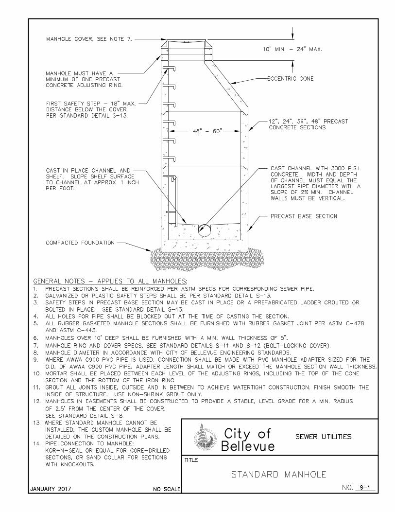
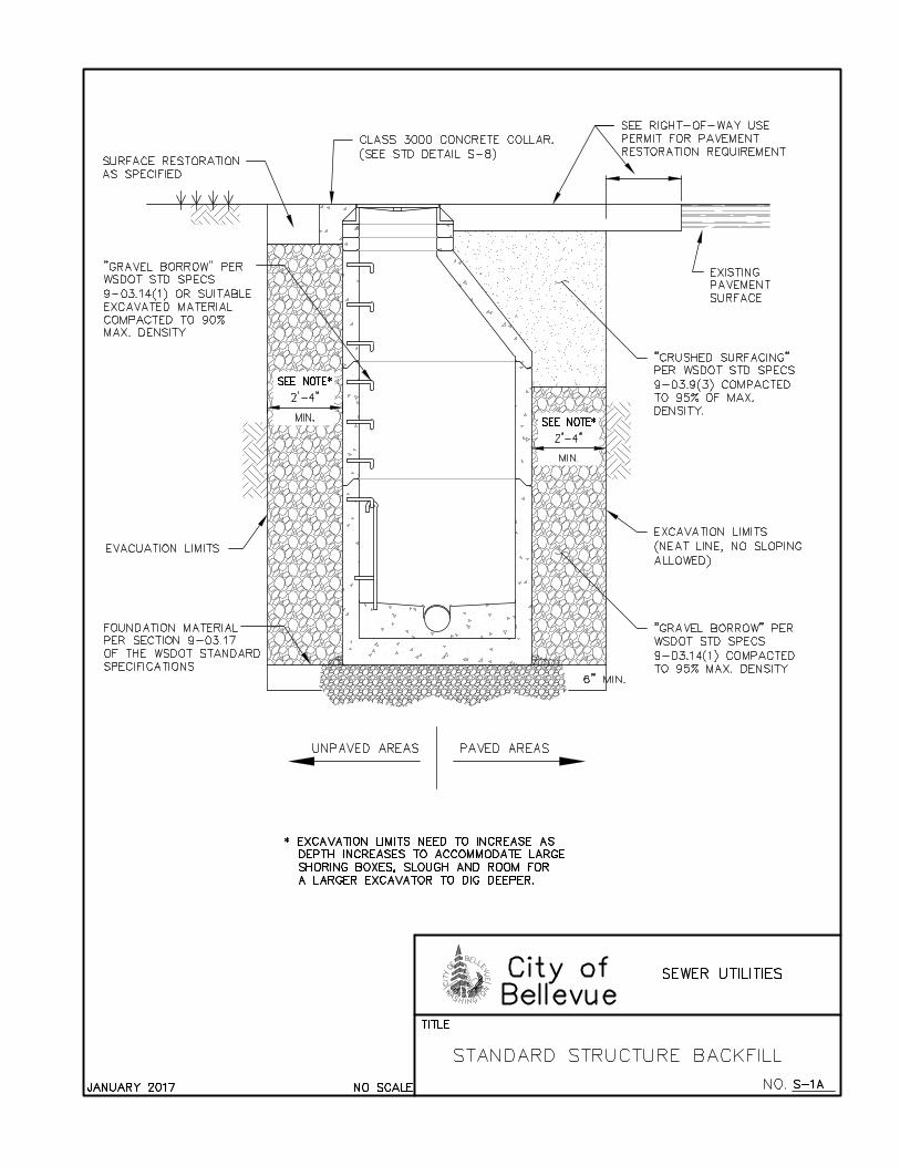
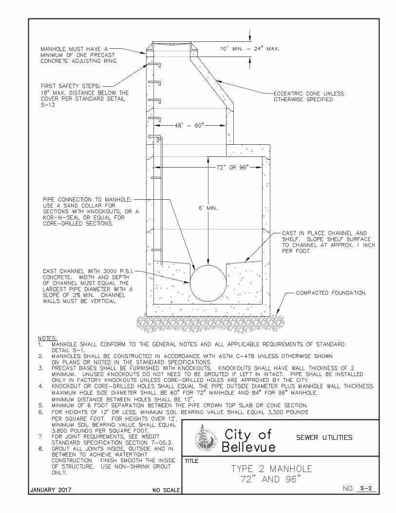
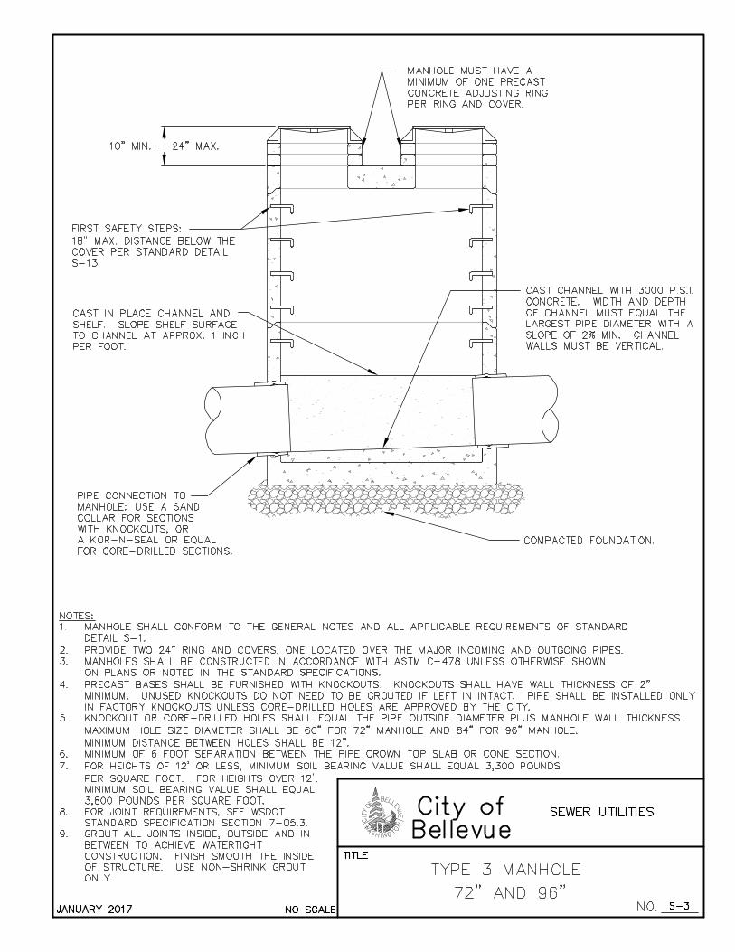
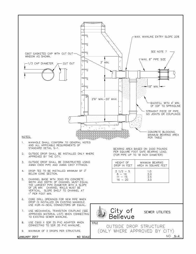
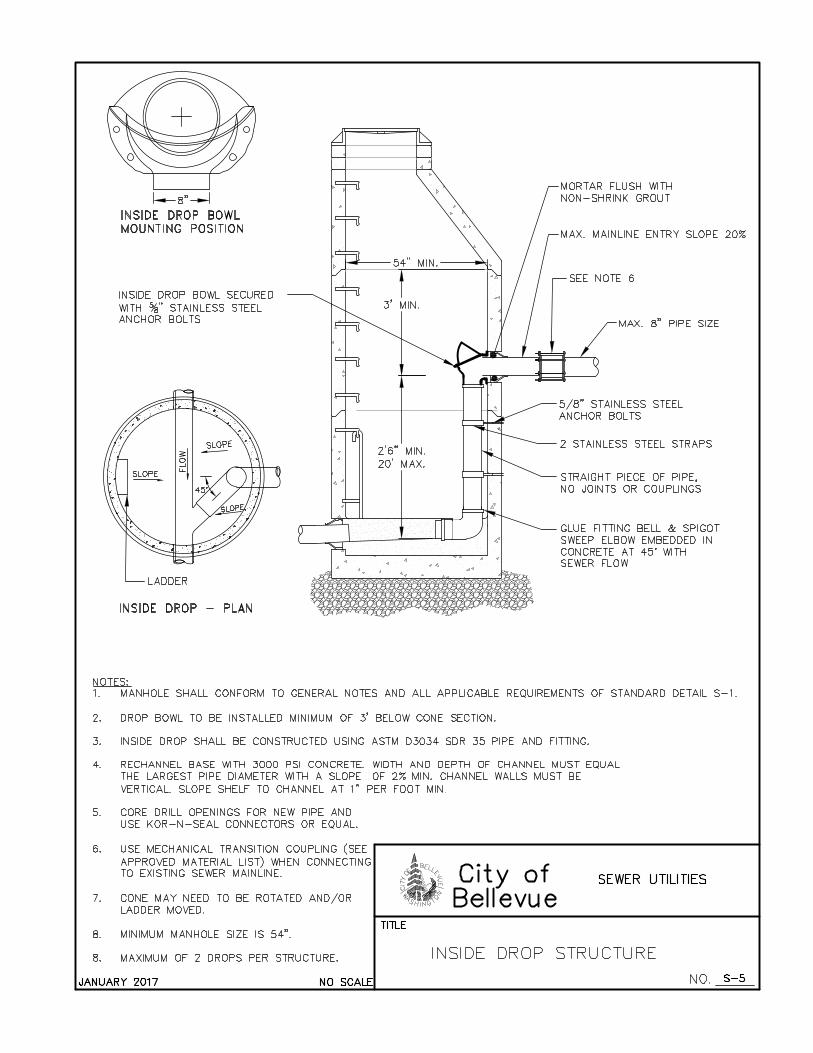
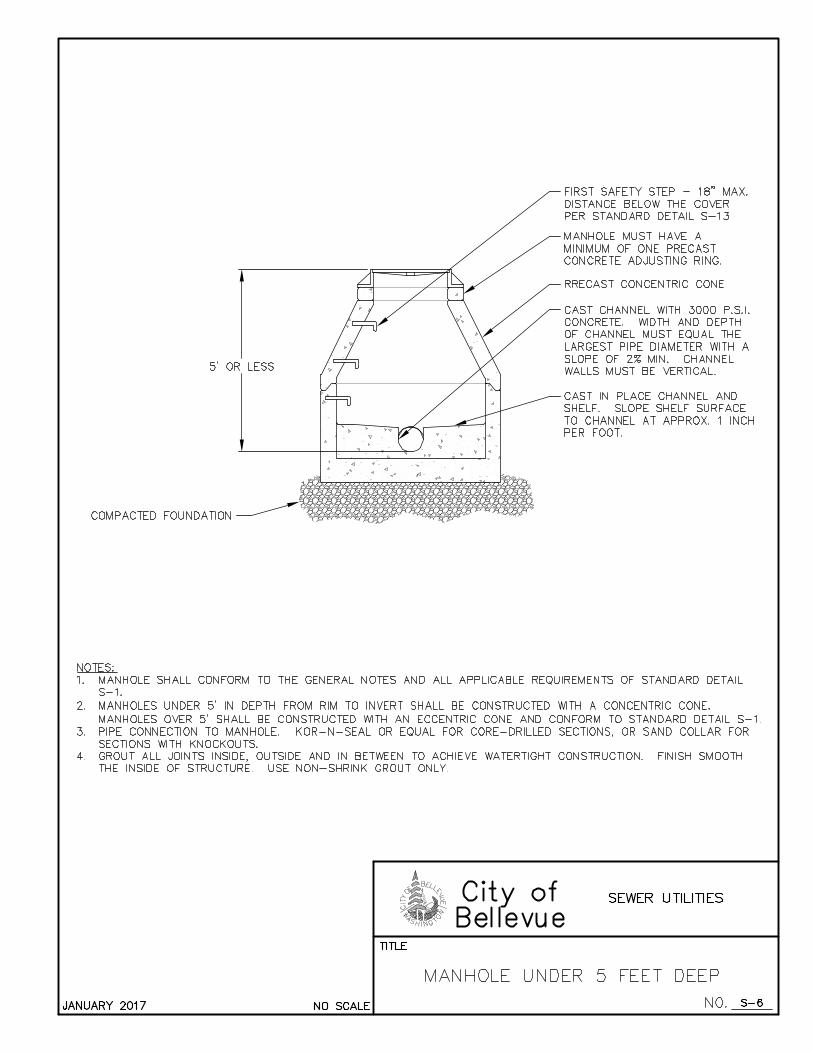
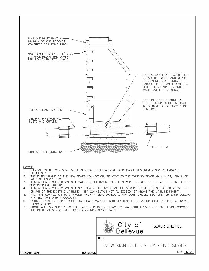
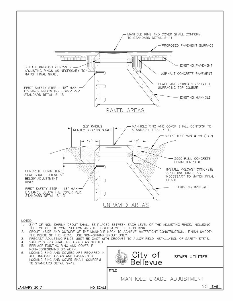
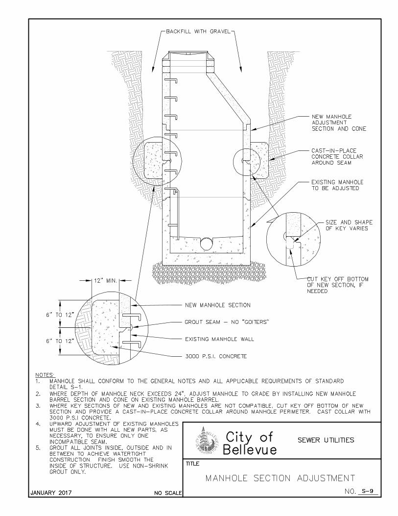

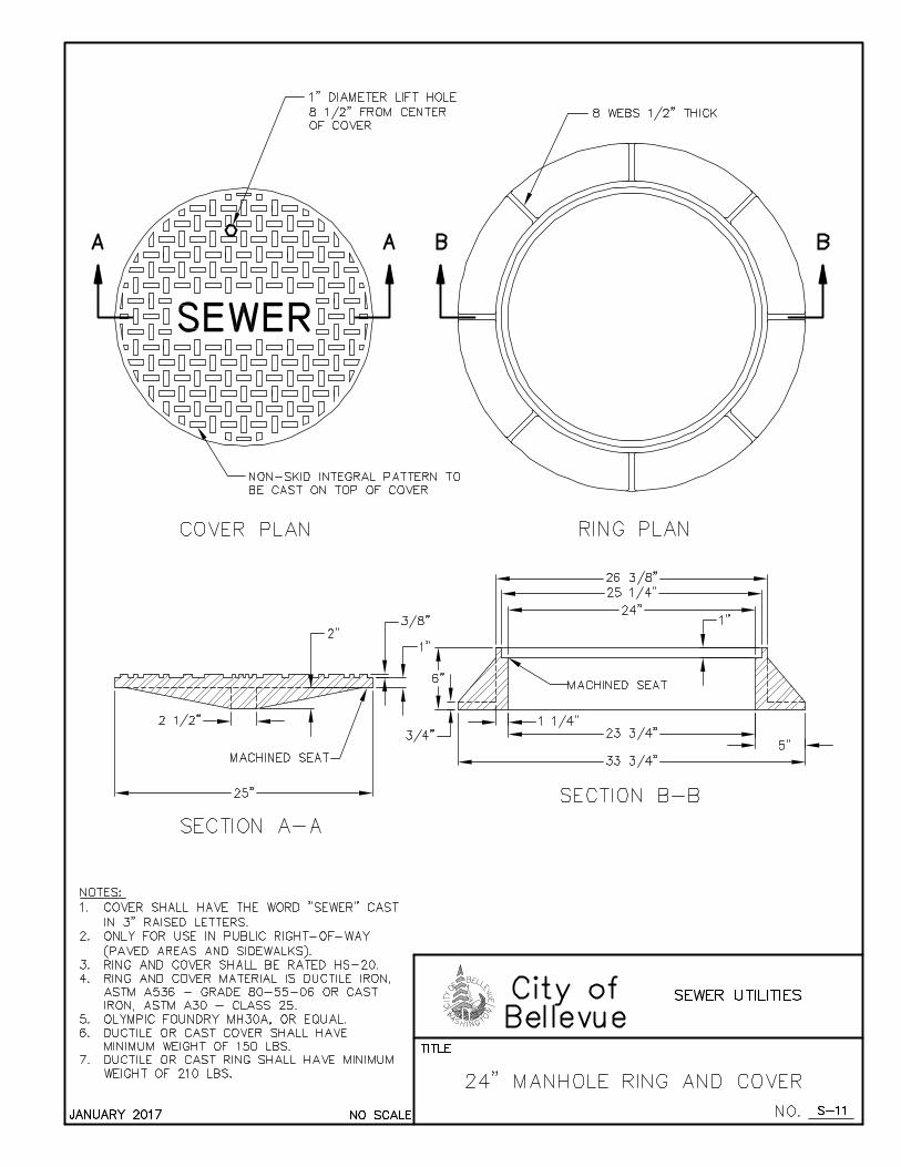
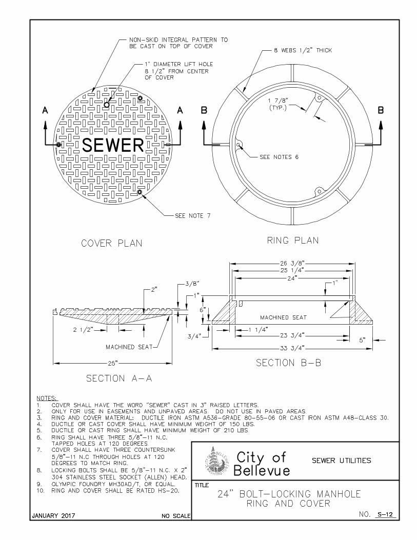
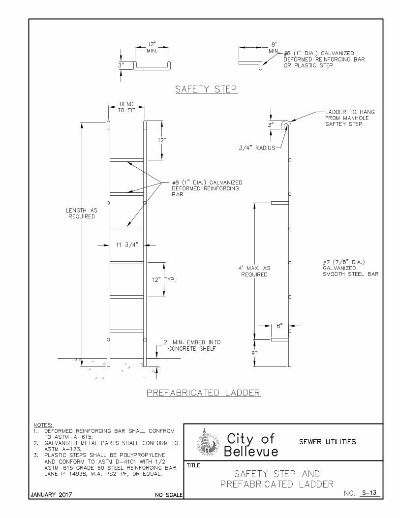
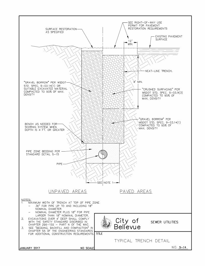

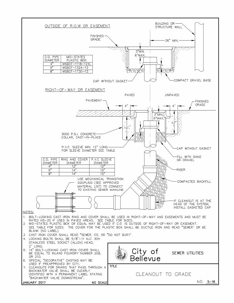
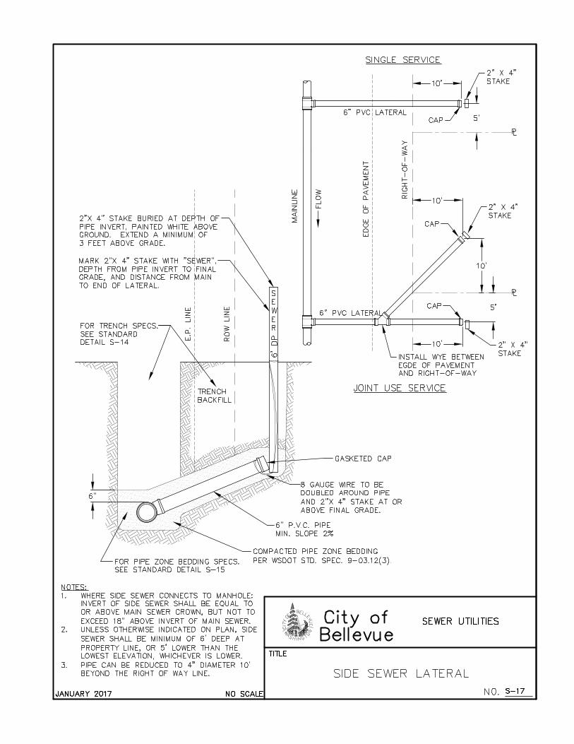
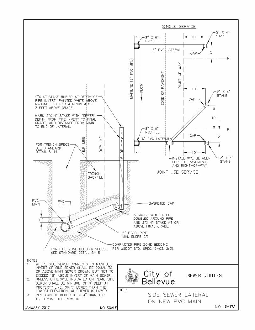
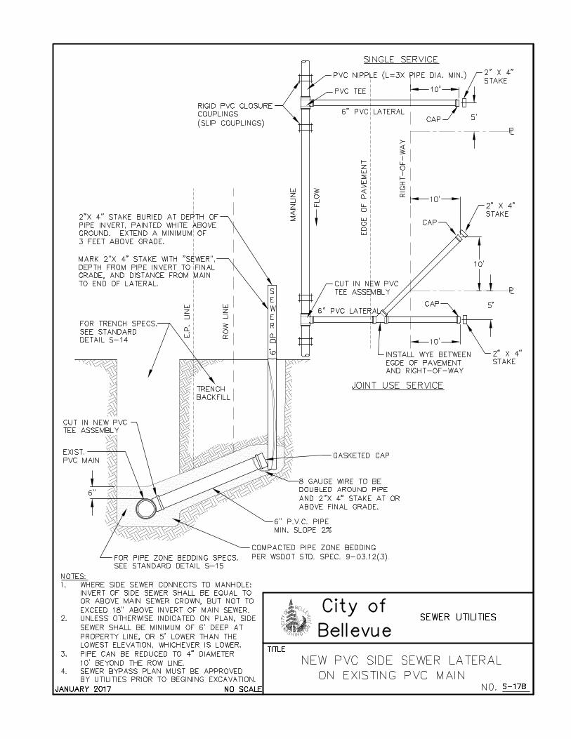
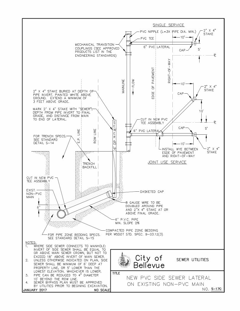
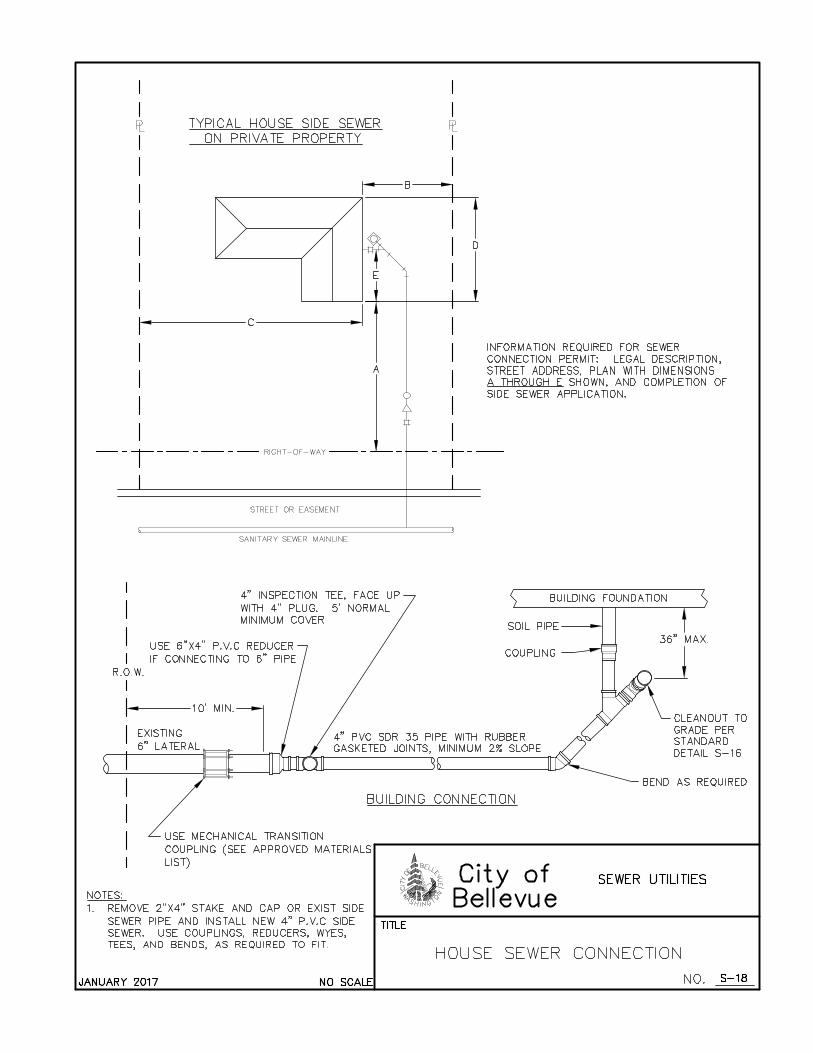
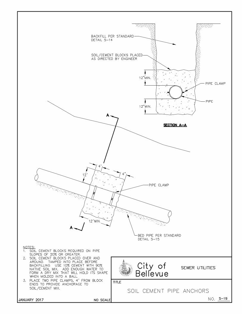
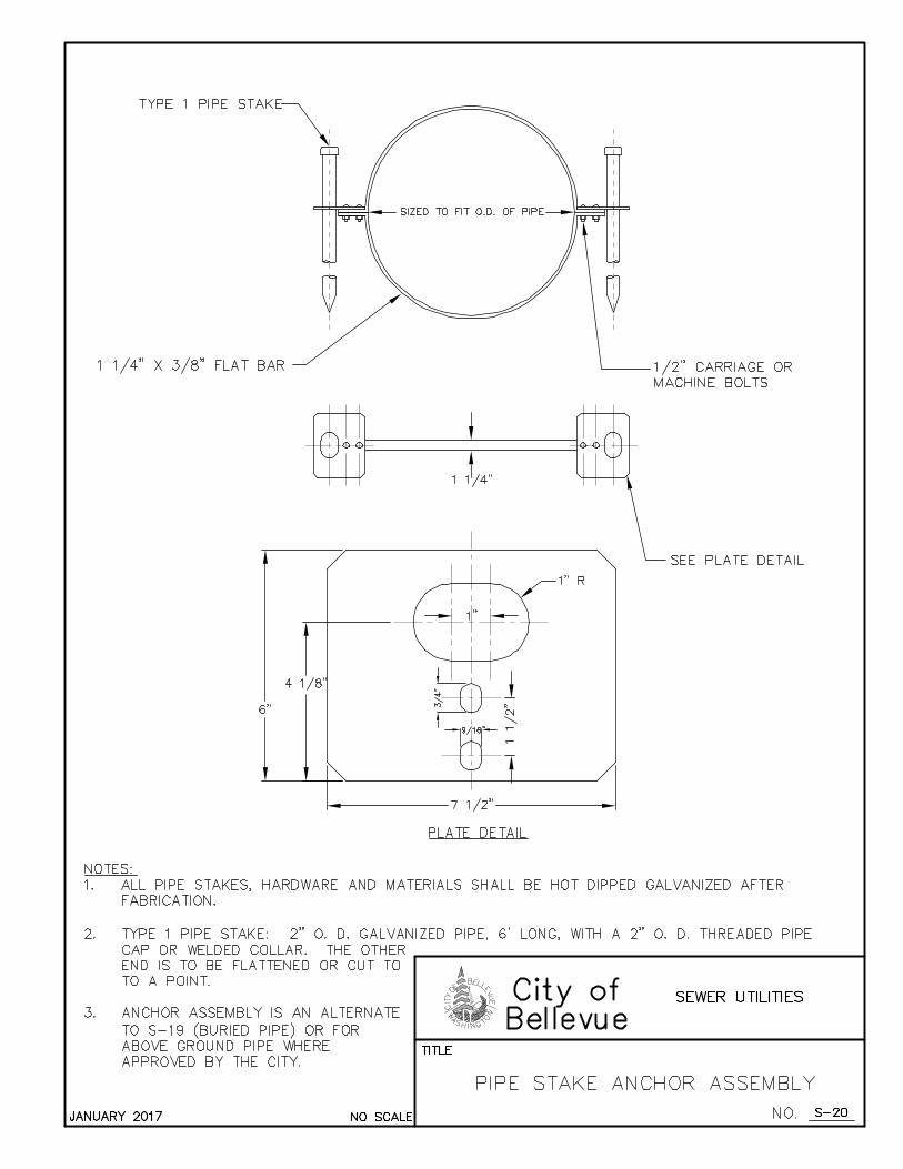
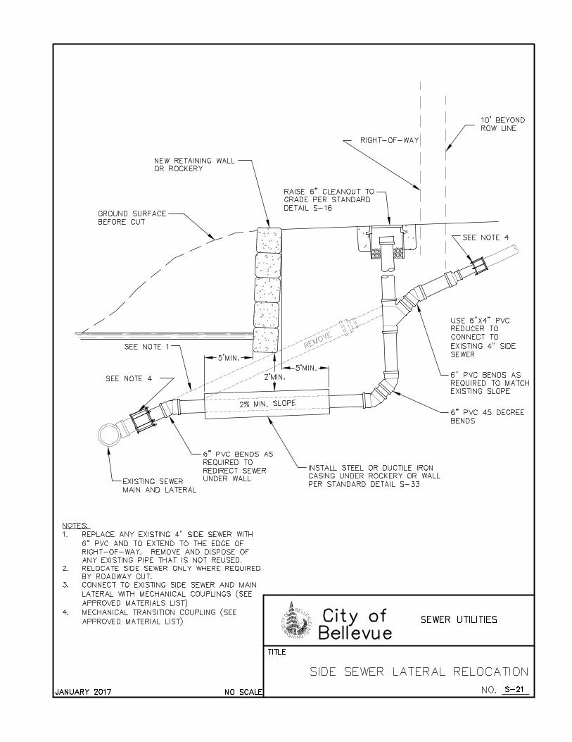
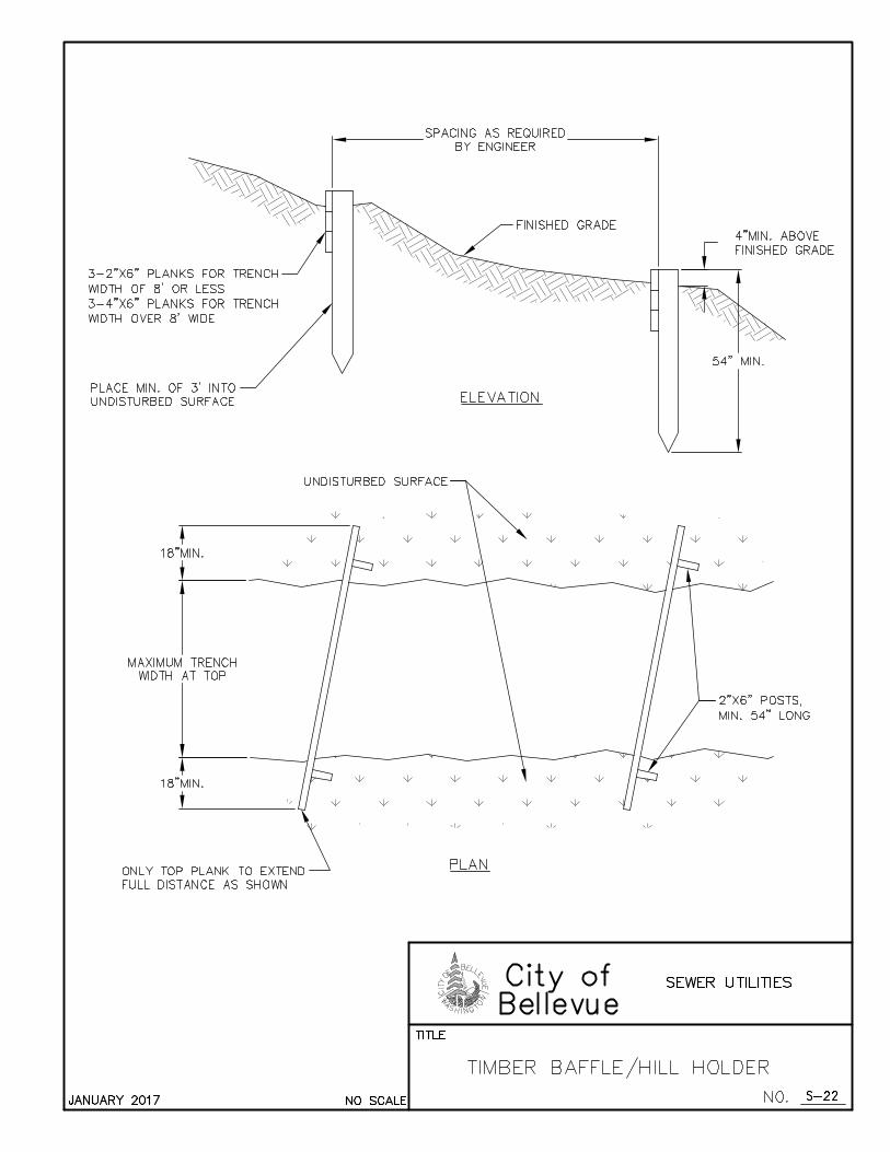
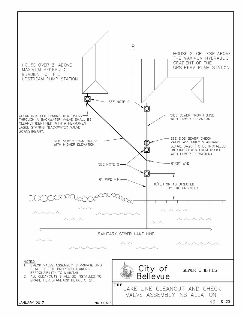
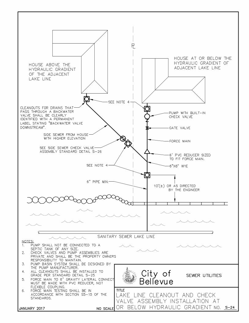
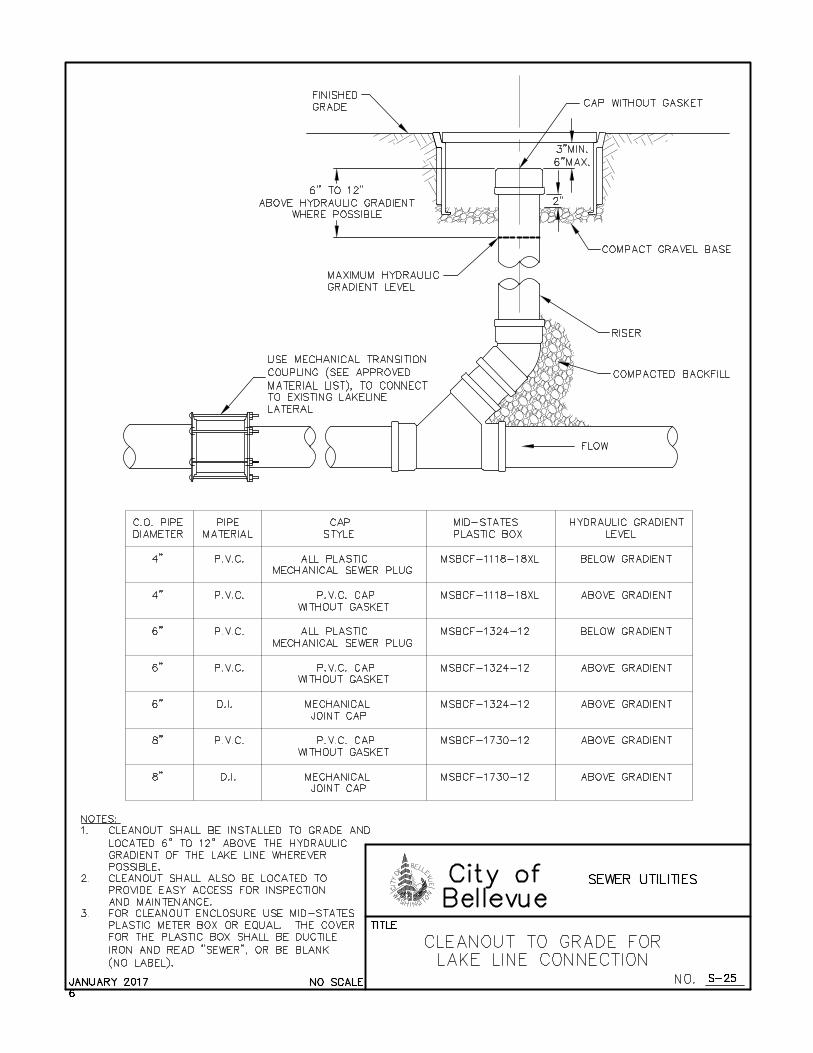


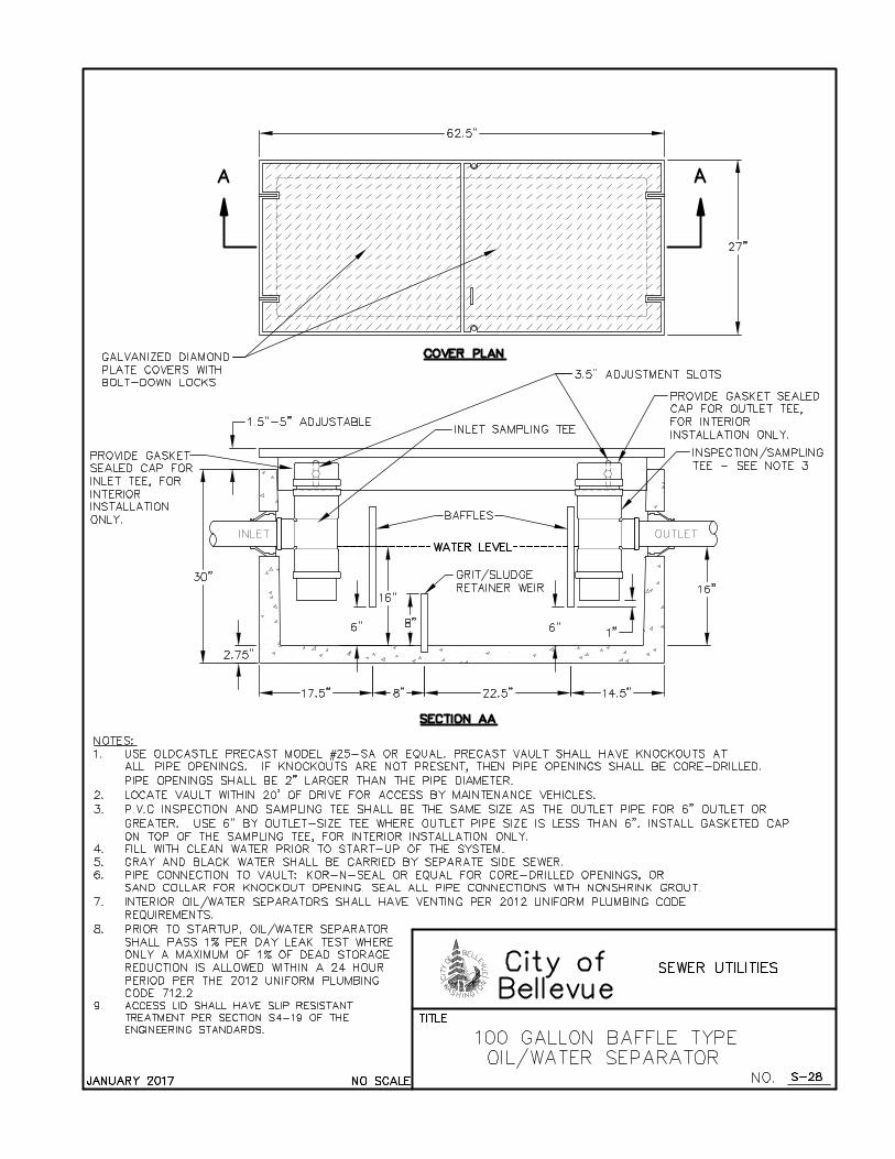
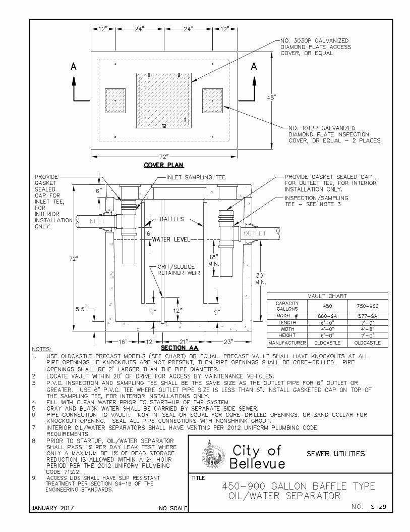

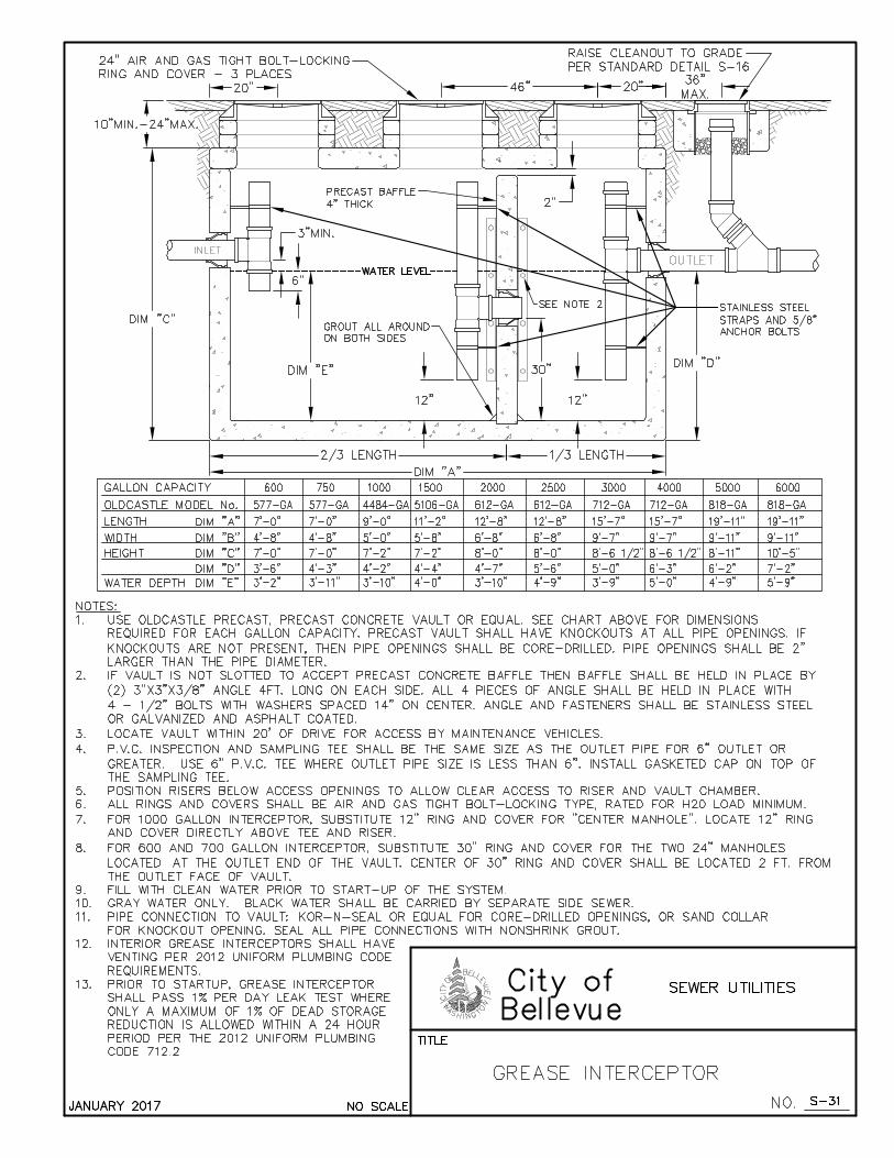
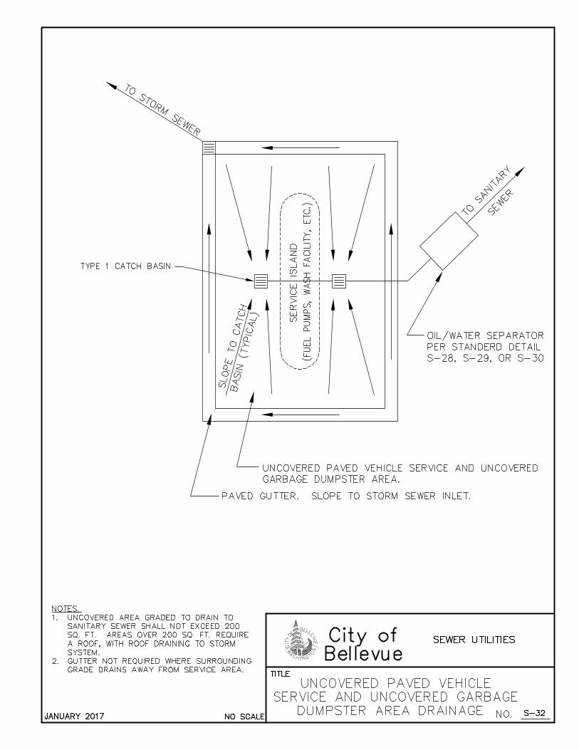
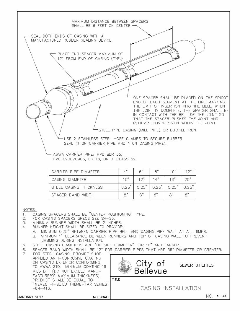
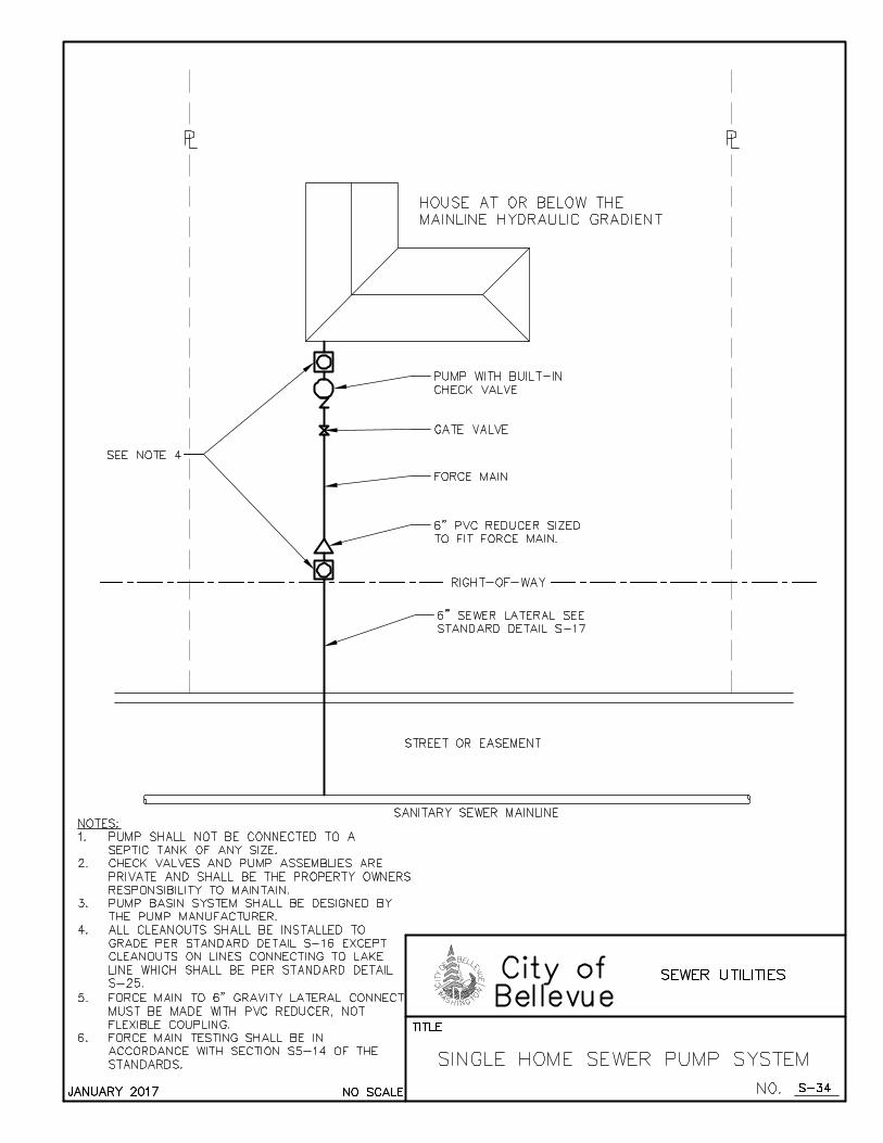
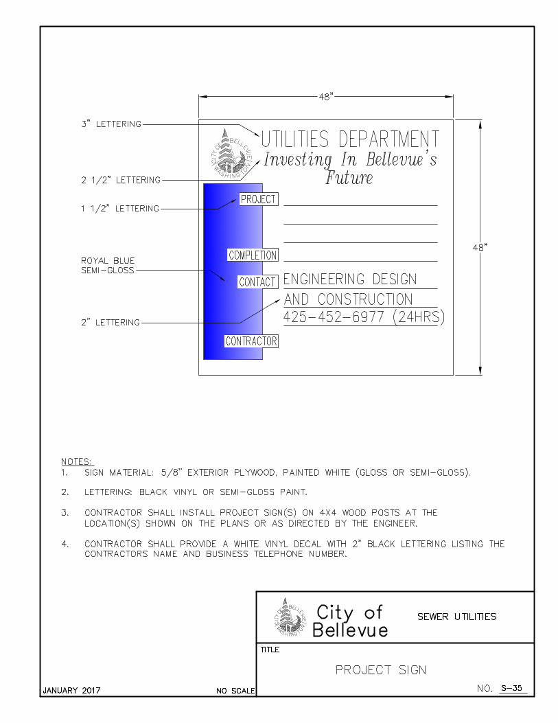
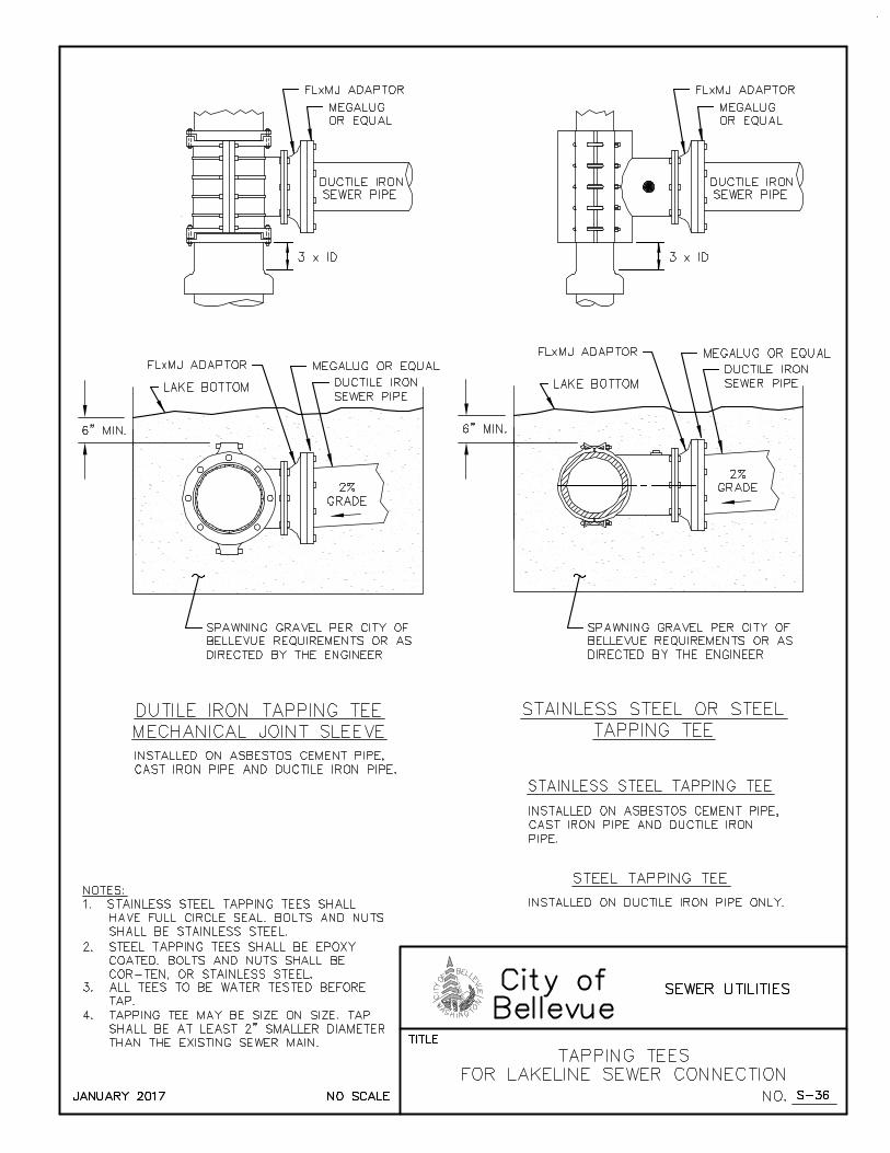
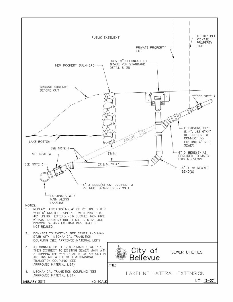
SANITARY SEWER ENGINEERING STANDARDS JANUARY 2017
A(S2 - 1)
APPENDIX S-2
DRAFTING STANDARDS
Also available in AutoCAD format at:
http://www.bellevuewa.gov/utilities_maps_forms.htm
WATER SYMBOLS ........................................................................................................... PAGE 1
SANITARY/STORM SEWER SYMBOLS ........................................................................ PAGE 2
SURVEY SYMBOLS .......................................................................................................... PAGE 3
SURFACE FEATURES/LANDSCAPE SYMBOLS .......................................................... PAGE 4
SIGNALIZATION SYMBOLS ........................................................................................... PAGE 5
CHANNELIZATION SYMBOLS ...................................................................................... PAGE 7
GAS/POWER/TELEPHONE SYMBOLS .......................................................................... PAGE 8
SURFACE FEATURES LINE TYPES ............................................................................... PAGE 9
SURVEY LINE TYPES .................................................................................................... PAGE 10
UTILITIES LINE TYPES ................................................................................................. PAGE 11
TEXT STYLES .................................................................................................................. PAGE 12
NOTES ............................................................................................................................... PAGE 12
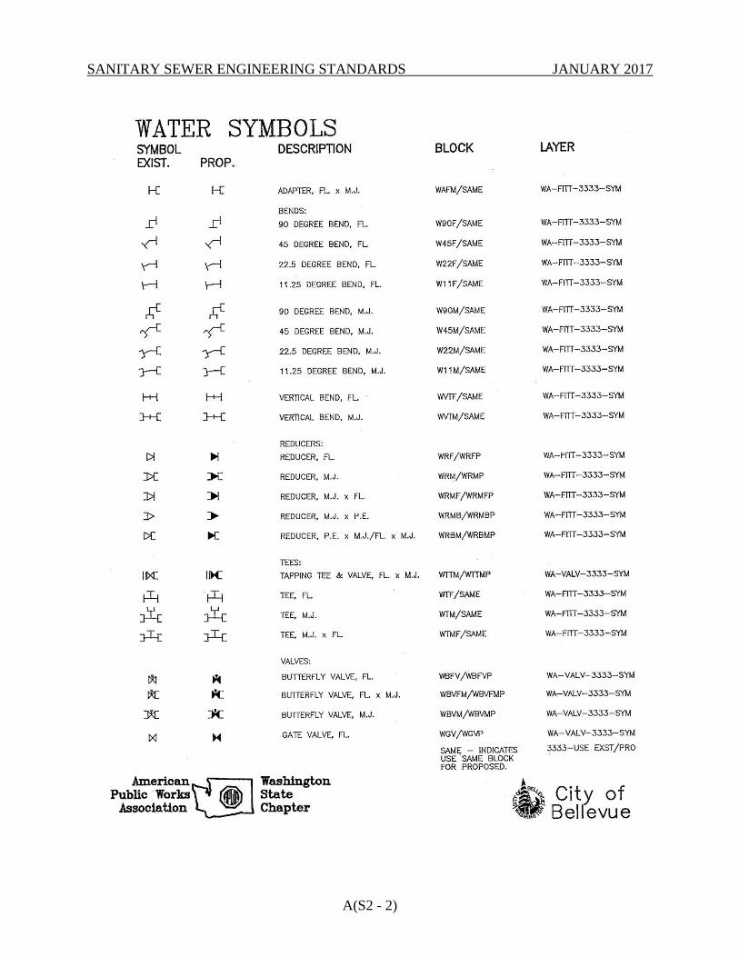
SANITARY SEWER ENGINEERING STANDARDS JANUARY 2017
A(S2 - 2)
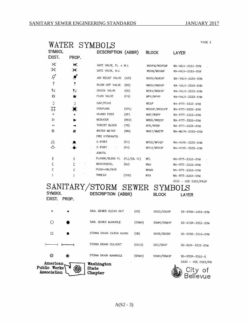
SANITARY SEWER ENGINEERING STANDARDS JANUARY 2017
A(S2 - 3)
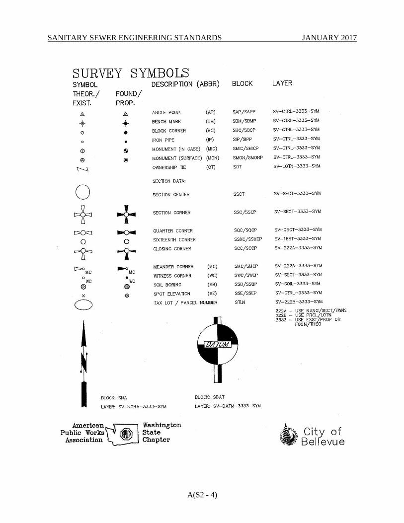
SANITARY SEWER ENGINEERING STANDARDS JANUARY 2017
A(S2 - 4)

SANITARY SEWER ENGINEERING STANDARDS JANUARY 2017
A(S2 - 5)
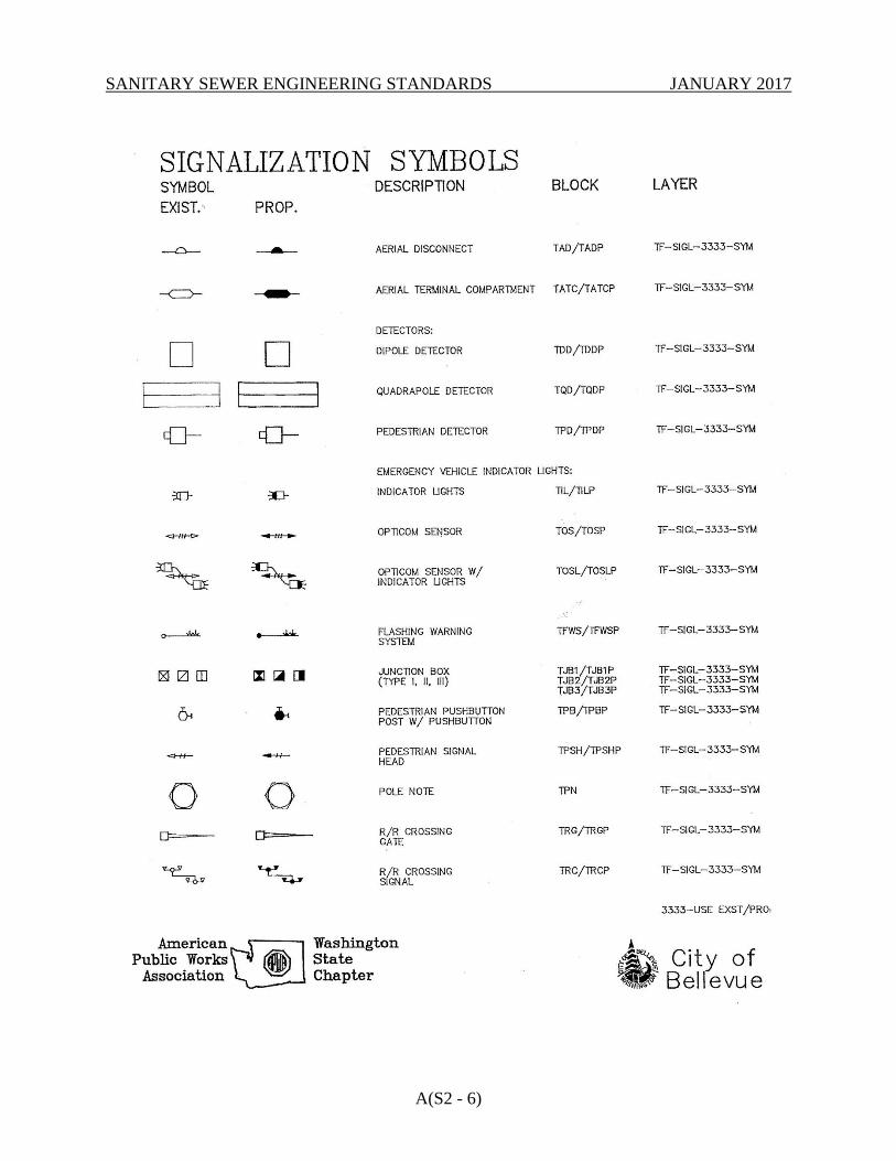
SANITARY SEWER ENGINEERING STANDARDS JANUARY 2017
A(S2 - 6)
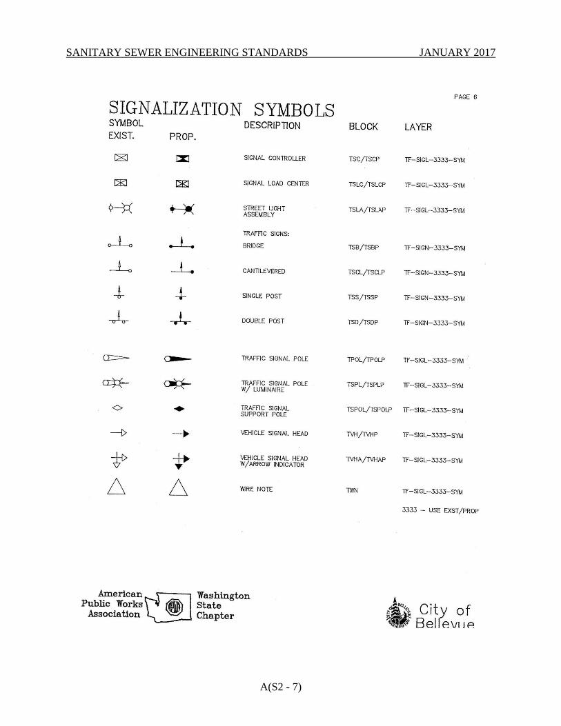
SANITARY SEWER ENGINEERING STANDARDS JANUARY 2017
A(S2 - 7)
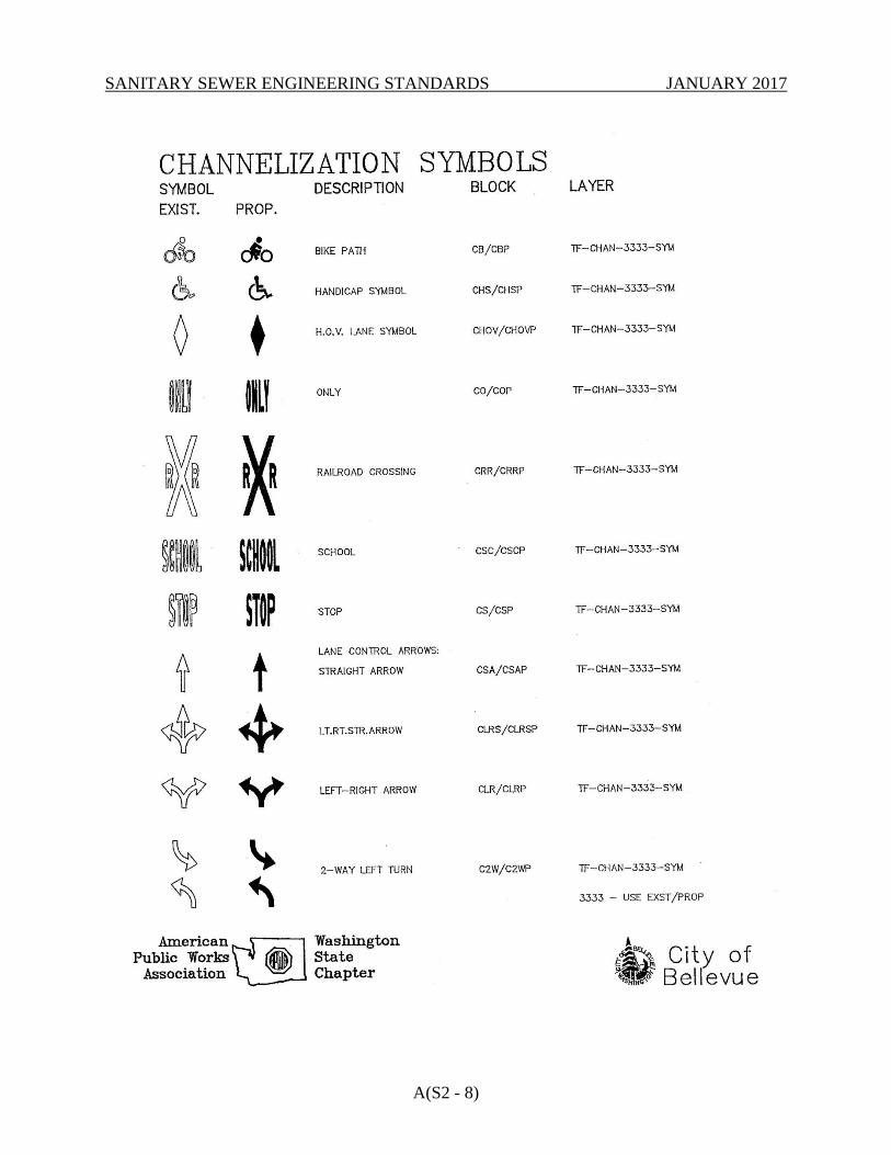
SANITARY SEWER ENGINEERING STANDARDS JANUARY 2017
A(S2 - 8)
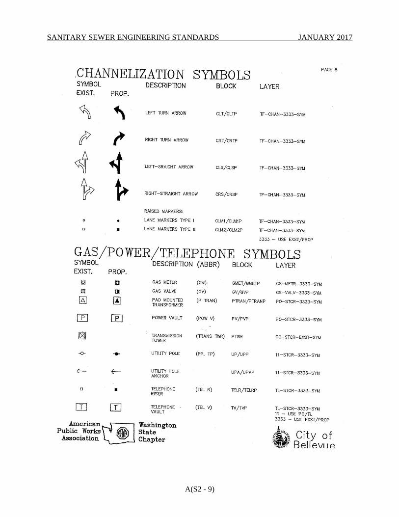
SANITARY SEWER ENGINEERING STANDARDS JANUARY 2017
A(S2 - 9)

SANITARY SEWER ENGINEERING STANDARDS JANUARY 2017
A(S2 - 10)
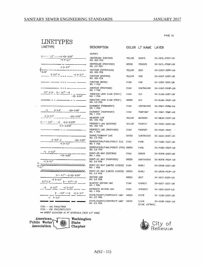
SANITARY SEWER ENGINEERING STANDARDS JANUARY 2017
A(S2 - 11)
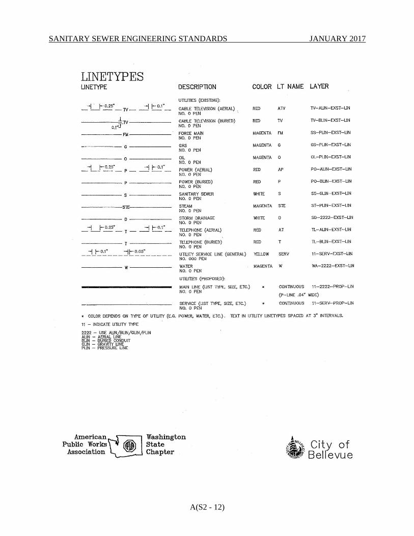
SANITARY SEWER ENGINEERING STANDARDS JANUARY 2017
A(S2 - 12)
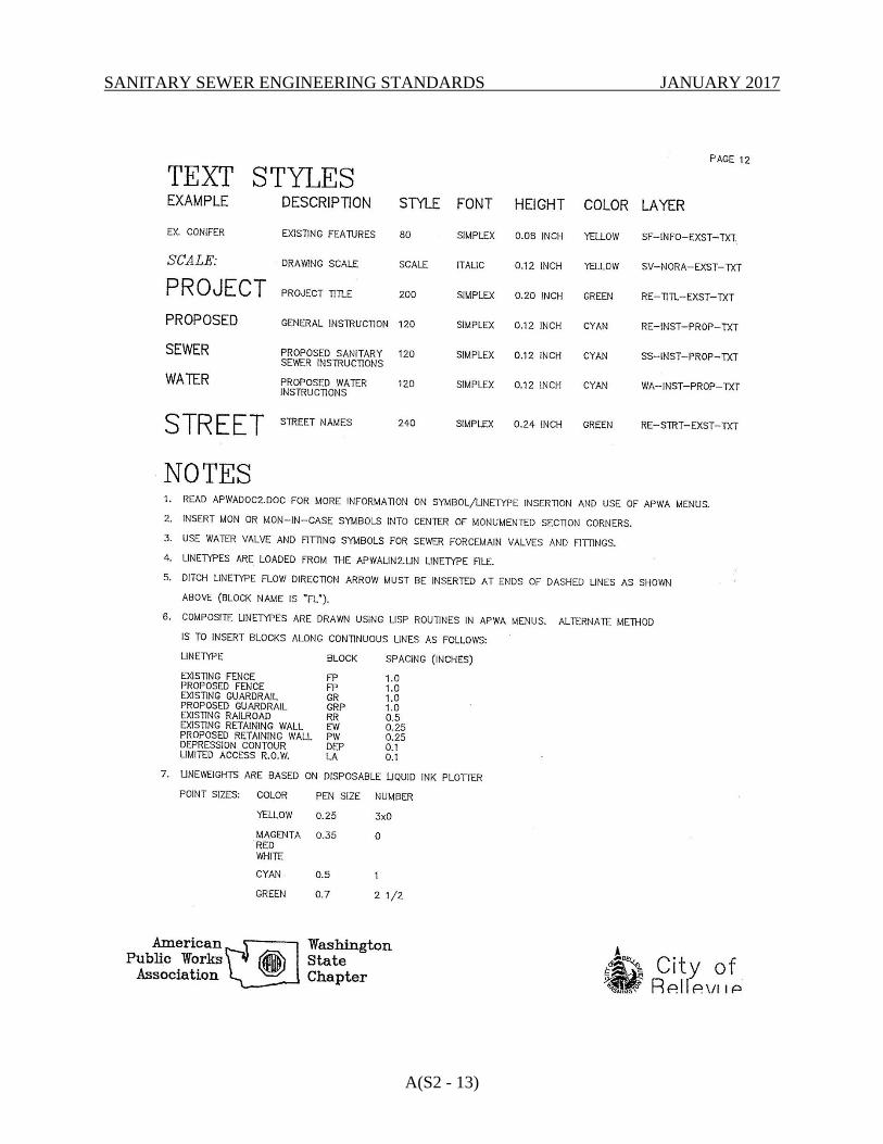
SANITARY SEWER ENGINEERING STANDARDS JANUARY 2017
A(S2 - 13)
SANITARY SEWER ENGINEERING STANDARDS JANUARY 2017
A(S2 - 1)
APPENDIX S-3
SAMPLE TITLE BLOCK
Also available in AutoCAD format at:
http://www.bellevuewa.gov/utilities_maps_forms.htm
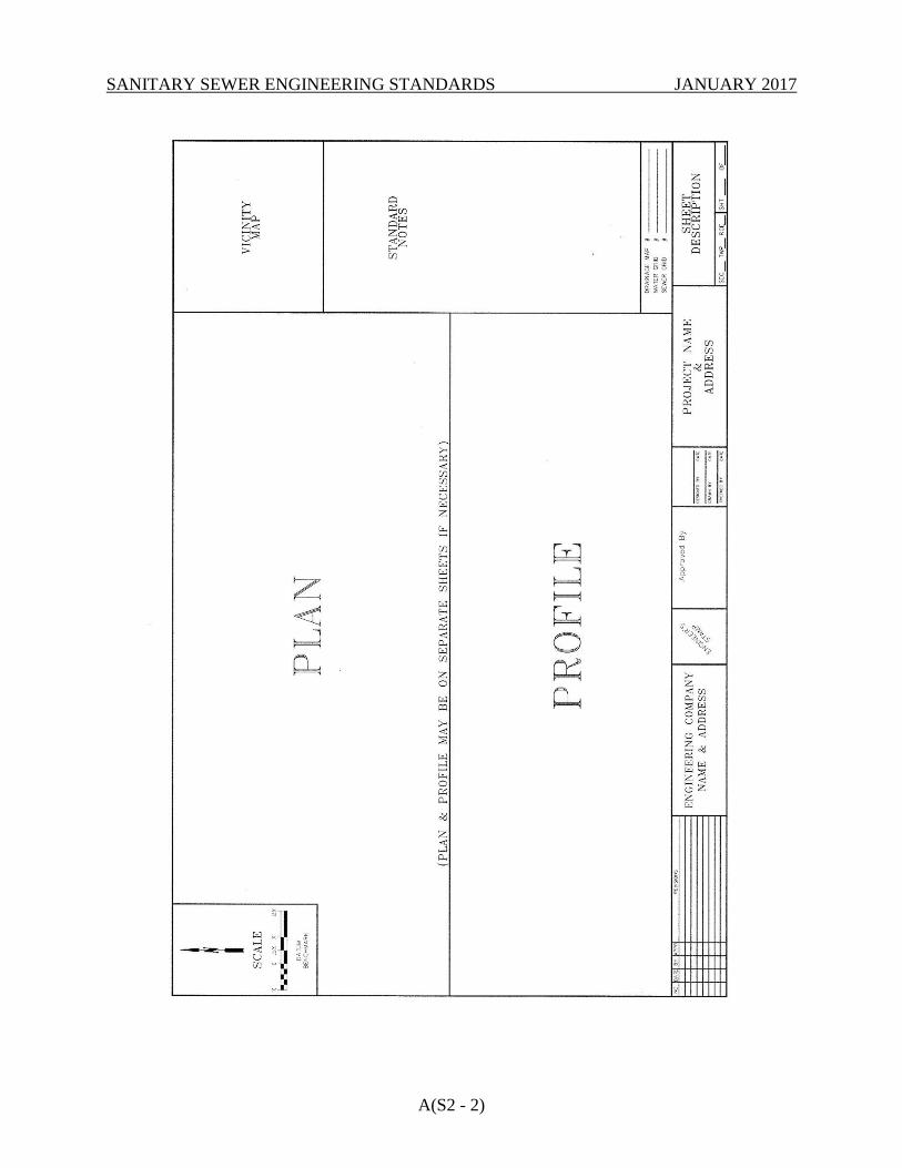
SANITARY SEWER ENGINEERING STANDARDS JANUARY 2017
A(S2 - 2)

SANITARY SEWER ENGINEERING STANDARDS JANUARY 2017
A(S4 - 1)
APPENDIX S-4
SEWER APPROVED MATERIALS LIST
The following manufacturers have been approved for use for sanitary sewer construction. Where
specific manufacturers are listed, no other manufacturer may be used without prior approval by
the Utility.
DUCTILE IRON PIPE
All manufacturers that meet the performance requirements specified under the material section of
the Standards.
DUCTILE IRON FITTINGS
All manufacturers that meet the performance requirements specified under the material section of
the Standards.
GALVANIZED IRON PIPE
All manufacturers that meet the performance requirements specified under the material section of
the Standards.
JOINT RESTRAINT SYSTEMS
American Ductile Iron Pipe (Flex-Ring)
EBAA Iron (MEGALUG 1100 Series)
EBAA Iron (MEGAFLANGE 2100 Series)
Griffin Pipe Products Company (Snap-Lok, Bolt-Lok)
Pacific States Cast Iron Pipe Co, (Thrust Lock)
Romac (Grip Ring), 600 Series, RomaGrip
Romac (Bell Restraint) 611 with 316SS stainless steel nuts and bolts
Star National Products (Shackle Products) - All rods and hardware shall be 316SS
stainless steel.
Cooper B-Line B3373 for PCV – 316SS stainless steel pipe clamps (embedded in
concrete blocks)
B3373F for Cast iron, Ductile iron, or C-900 – 316SS stainless steel pipe clamps
(embedded in concrete blocks)
US Pipe (TR FLEX)
Uni-Flange Corporation Series 1400, or Series 1450 with 316SS stainless steel nuts and bolts
PIPE CLAMP FOR SEWER SOIL CEMENT PIPE ANCHORS
Cooper B-Line B3373 for PCV– Hot Dipped Galvanized (embedded in Soil Cement)
B3373F for Cast iron, Ductile iron, or C-900 – Hot Dipped Galvanized (embedded in
Soil Cement)

SANITARY SEWER ENGINEERING STANDARDS JANUARY 2017
A(S4 - 2)
COUPLINGS
Romac (400 and 501 Series), Dresser, Smith-Blair (Rockwell), Mueller MaxiFit, Mueller
MaxiStep
SADDLE TAP FOR SIDE SEWER
Romac Style CB Sewer Saddle
REPAIR CLAMPS
Romac Industries, Models SS1 and SS2
CASING (COATING FOR STEEL CASING)
Tnemec Hi-Build Tneme-Tar, Series 46H-413
CASING SPACERS
Pipeline Seal and Insulator Co.:
8" band, carbon steel with fusion-bonded coating, Model C8G-2
12" band, carbon steel with fusion-bonded coating, Model C12G-2
Cascade Waterworks Mfg. Co.:
Stainless Steel or hot-dip galvanized carbon steel Casing Spacers (catalog number depends
on size)
Advance Products & Systems, Inc.:
8" band, stainless steel, Model SSI8
12" band, stainless steel, Model SSI12
8" band, carbon steel with fusion-bonded coating, Model SI8
12" band, carbon steel with fusion-bonded coating, Model SI12
CASING END SEALS
Pipeline Seal and Insulator Co.:
Standard Pull-on (Model S)
Custom Pull-on (Model C)
Cascade Waterworks Mfg. Co.:
CCES End Seal
Advance Products & Systems, Inc.
Molded End Seal, Model AM
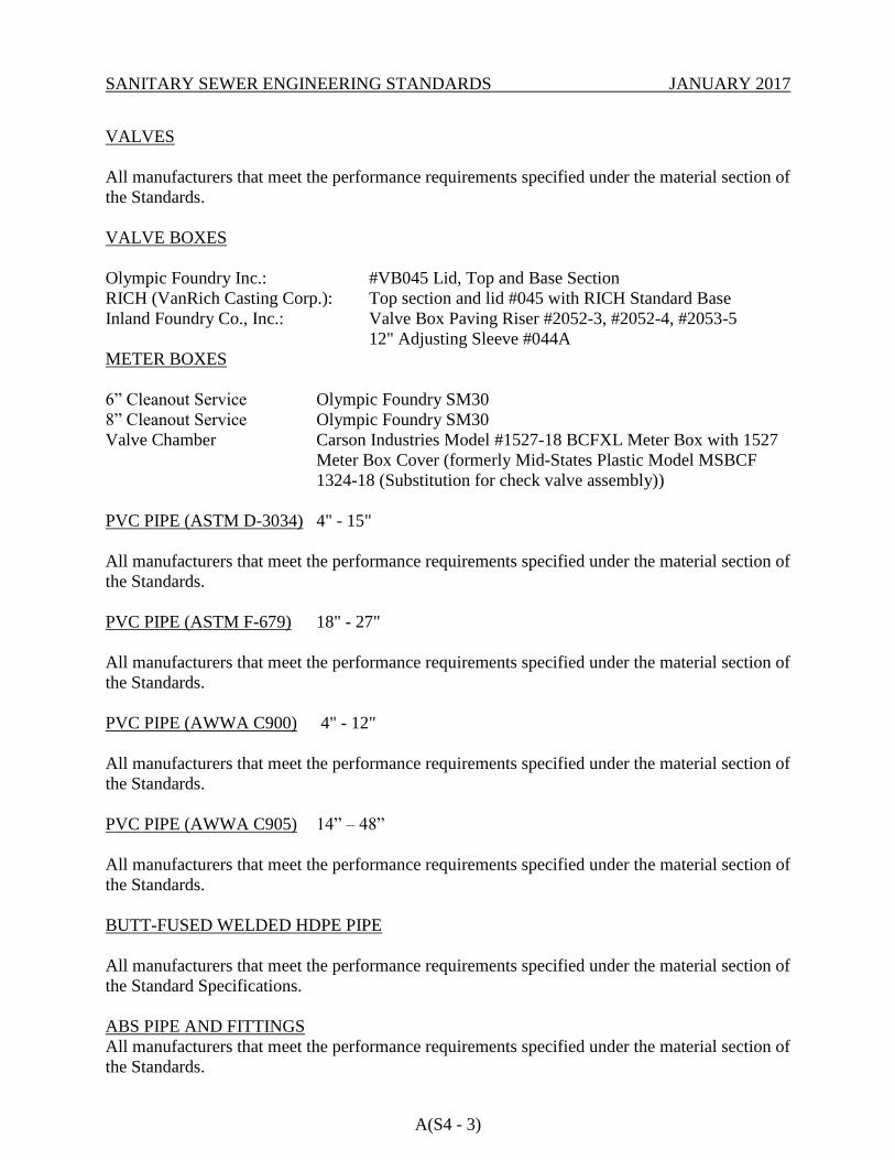
SANITARY SEWER ENGINEERING STANDARDS JANUARY 2017
A(S4 - 3)
VALVES
All manufacturers that meet the performance requirements specified under the material section of
the Standards.
VALVE BOXES
Olympic Foundry Inc.: #VB045 Lid, Top and Base Section
RICH (VanRich Casting Corp.): Top section and lid #045 with RICH Standard Base
Inland Foundry Co., Inc.: Valve Box Paving Riser #2052-3, #2052-4, #2053-5
12" Adjusting Sleeve #044A
METER BOXES
6” Cleanout Service Olympic Foundry SM30
8” Cleanout Service Olympic Foundry SM30
Valve Chamber Carson Industries Model #1527-18 BCFXL Meter Box with 1527
Meter Box Cover (formerly Mid-States Plastic Model MSBCF
1324-18 (Substitution for check valve assembly))
PVC PIPE (ASTM D-3034) 4" - 15"
All manufacturers that meet the performance requirements specified under the material section of
the Standards.
PVC PIPE (ASTM F-679) 18" - 27"
All manufacturers that meet the performance requirements specified under the material section of
the Standards.
PVC PIPE (AWWA C900) 4" - 12"
All manufacturers that meet the performance requirements specified under the material section of
the Standards.
PVC PIPE (AWWA C905) 14” – 48”
All manufacturers that meet the performance requirements specified under the material section of
the Standards.
BUTT-FUSED WELDED HDPE PIPE
All manufacturers that meet the performance requirements specified under the material section of
the Standard Specifications.
ABS PIPE AND FITTINGS
All manufacturers that meet the performance requirements specified under the material section of
the Standards.
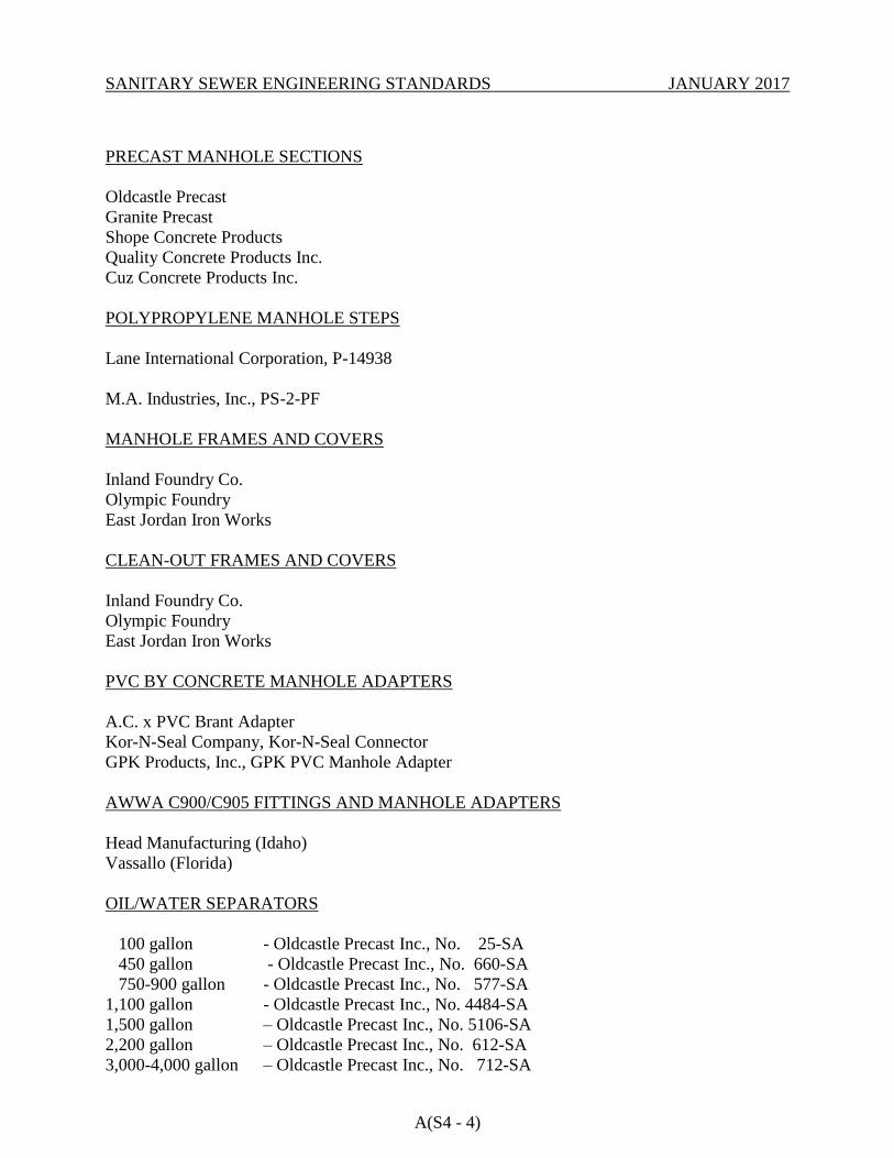
SANITARY SEWER ENGINEERING STANDARDS JANUARY 2017
A(S4 - 4)
PRECAST MANHOLE SECTIONS
Oldcastle Precast
Granite Precast
Shope Concrete Products
Quality Concrete Products Inc.
Cuz Concrete Products Inc.
POLYPROPYLENE MANHOLE STEPS
Lane International Corporation, P-14938
M.A. Industries, Inc., PS-2-PF
MANHOLE FRAMES AND COVERS
Inland Foundry Co.
Olympic Foundry
East Jordan Iron Works
CLEAN-OUT FRAMES AND COVERS
Inland Foundry Co.
Olympic Foundry
East Jordan Iron Works
PVC BY CONCRETE MANHOLE ADAPTERS
A.C. x PVC Brant Adapter
Kor-N-Seal Company, Kor-N-Seal Connector
GPK Products, Inc., GPK PVC Manhole Adapter
AWWA C900/C905 FITTINGS AND MANHOLE ADAPTERS
Head Manufacturing (Idaho)
Vassallo (Florida)
OIL/WATER SEPARATORS
100 gallon - Oldcastle Precast Inc., No. 25-SA
450 gallon - Oldcastle Precast Inc., No. 660-SA
750-900 gallon - Oldcastle Precast Inc., No. 577-SA
1,100 gallon - Oldcastle Precast Inc., No. 4484-SA
1,500 gallon – Oldcastle Precast Inc., No. 5106-SA
2,200 gallon – Oldcastle Precast Inc., No. 612-SA
3,000-4,000 gallon – Oldcastle Precast Inc., No. 712-SA
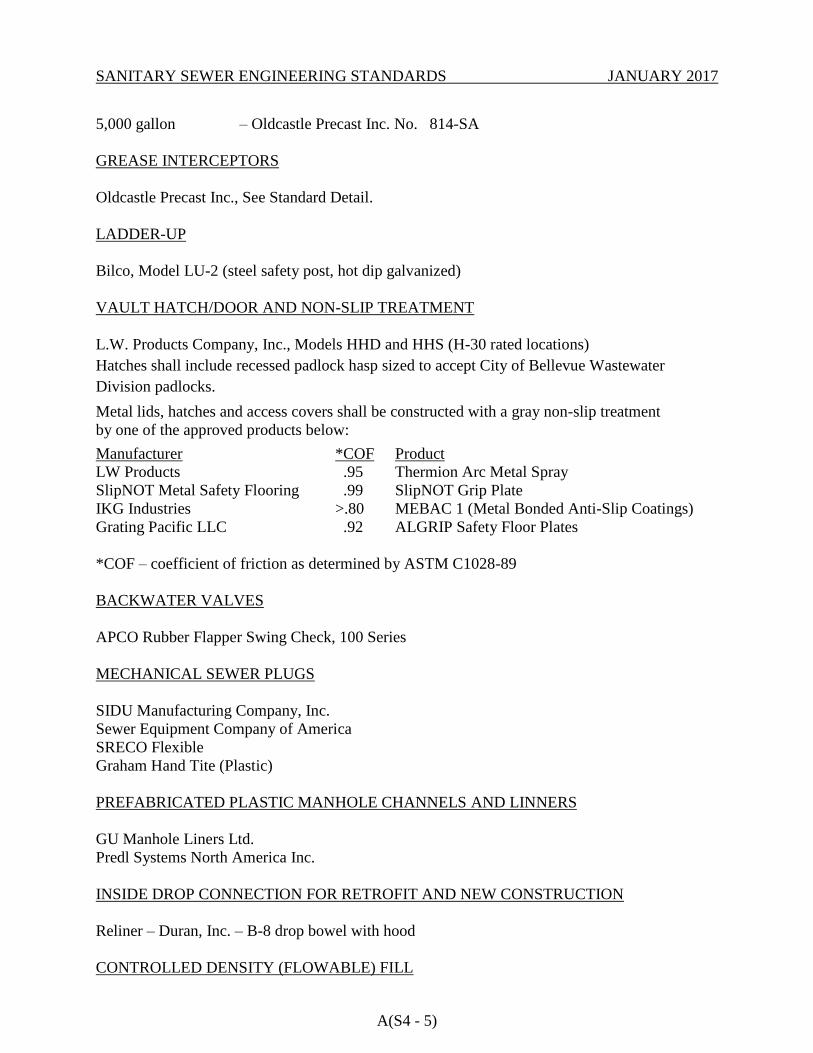
SANITARY SEWER ENGINEERING STANDARDS JANUARY 2017
A(S4 - 5)
5,000 gallon – Oldcastle Precast Inc. No. 814-SA
GREASE INTERCEPTORS
Oldcastle Precast Inc., See Standard Detail.
LADDER-UP
Bilco, Model LU-2 (steel safety post, hot dip galvanized)
VAULT HATCH/DOOR AND NON-SLIP TREATMENT
L.W. Products Company, Inc., Models HHD and HHS (H-30 rated locations)
Hatches shall include recessed padlock hasp sized to accept City of Bellevue Wastewater
Division padlocks.
Metal lids, hatches and access covers shall be constructed with a gray non-slip treatment
by one of the approved products below:
Manufacturer *COF Product
LW Products .95 Thermion Arc Metal Spray
SlipNOT Metal Safety Flooring .99 SlipNOT Grip Plate
IKG Industries >.80 MEBAC 1 (Metal Bonded Anti-Slip Coatings)
Grating Pacific LLC .92 ALGRIP Safety Floor Plates
*COF – coefficient of friction as determined by ASTM C1028-89
BACKWATER VALVES
APCO Rubber Flapper Swing Check, 100 Series
MECHANICAL SEWER PLUGS
SIDU Manufacturing Company, Inc.
Sewer Equipment Company of America
SRECO Flexible
Graham Hand Tite (Plastic)
PREFABRICATED PLASTIC MANHOLE CHANNELS AND LINNERS
GU Manhole Liners Ltd.
Predl Systems North America Inc.
INSIDE DROP CONNECTION FOR RETROFIT AND NEW CONSTRUCTION
Reliner – Duran, Inc. – B-8 drop bowel with hood
CONTROLLED DENSITY (FLOWABLE) FILL
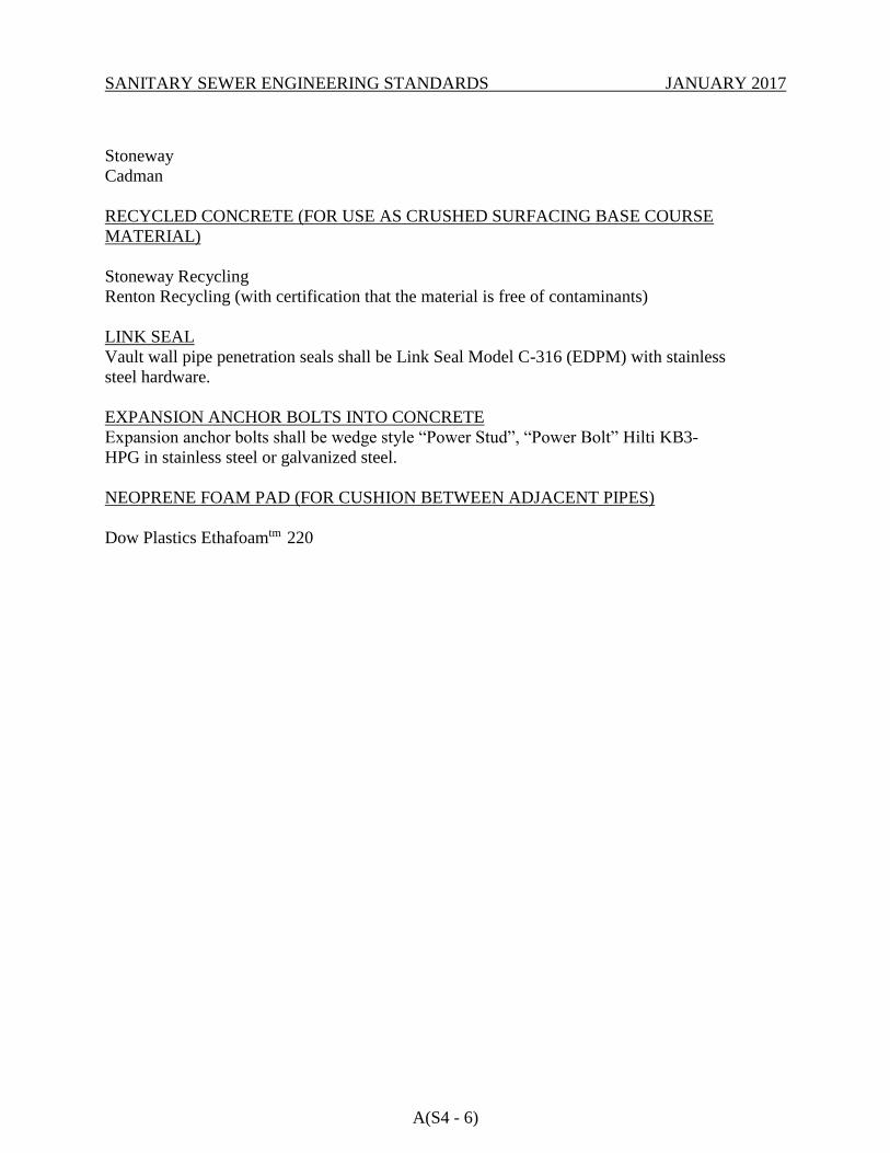
SANITARY SEWER ENGINEERING STANDARDS JANUARY 2017
A(S4 - 6)
Stoneway
Cadman
RECYCLED CONCRETE (FOR USE AS CRUSHED SURFACING BASE COURSE
MATERIAL)
Stoneway Recycling
Renton Recycling (with certification that the material is free of contaminants)
LINK SEAL
Vault wall pipe penetration seals shall be Link Seal Model C-316 (EDPM) with stainless
steel hardware.
EXPANSION ANCHOR BOLTS INTO CONCRETE
Expansion anchor bolts shall be wedge style “Power Stud”, “Power Bolt” Hilti KB3-
HPG in stainless steel or galvanized steel.
NEOPRENE FOAM PAD (FOR CUSHION BETWEEN ADJACENT PIPES)
Dow Plastics Ethafoamtm 220
SANITARY SEWER ENGINEERING STANDARDS JANUARY 2017
APPENDIX S-5
SANITARY SEWER REFERENCE STANDARDS
1. STANDARDS FOR UTILITIES INSTALLED IN PROXIMITY OF SEATTLE PUBLIC
UTILITIES TRANSMISSION PIPELINES.......................................................... A(S5 - 1)
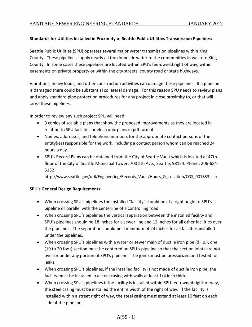
SANITARY SEWER ENGINEERING STANDARDS JANUARY 2017
A(S5 - 1)
Standards for Utilities Installed in Proximity of Seattle Public Utilities Transmission Pipelines:
Seattle Public Utilities (SPU) operates several major water transmission pipelines within King
County. These pipelines supply nearly all the domestic water to the communities in western King
County. In some cases these pipelines are located within SPU's fee-owned right of way, within
easements on private property or within the city streets, county road or state highways.
Vibrations, heavy loads, and other construction activities can damage these pipelines. If a pipeline
is damaged there could be substantial collateral damage. For this reason SPU needs to review plans
and apply standard pipe protection procedures for any project in close proximity to, or that will
cross these pipelines.
In order to review any such project SPU will need:
3 copies of scalable plans that show the proposed improvements as they are located in
relation to SPU facilities or electronic plans in pdf format.
Names, addresses, and telephone numbers for the appropriate contact persons of the
entity(ies) responsible for the work, including a contact person whom can be reached 24
hours a day.
SPU's Record Plans can be obtained from the City of Seattle Vault which is located at 47th
floor of the City of Seattle Municipal Tower, 700 5th Ave., Seattle, 98124. Phone: 206-684-
5132.
http://www.seattle.gov/util/Engineering/Records_Vault/Hours_&_Location/COS_001833.asp
SPU's General Design Requirements:
When crossing SPU's pipelines the installed "facility" should be at a right angle to SPU's
pipeline or parallel with the centerline of a controlling road.
When crossing SPU's pipelines the vertical separation between the installed facility and
SPU's pipelines should be 18 inches for a sewer line and 12 inches for all other facilities over
the pipelines. The separation should be a minimum of 24 inches for all facilities installed
under the pipelines.
When crossing SPU's pipelines with a water or sewer main of ductile iron pipe (d.i.p.), one
(19 to 20 foot) section must be centered on SPU's pipeline so that the section joints are not
over or under any portion of SPU's pipeline. The joints must be pressurized and tested for
leaks.
When crossing SPU's pipelines, if the installed facility is not made of ductile iron pipe, the
facility must be installed in a steel casing with walls at least 1/4 inch thick.
When crossing SPU’s pipelines if the facility is installed within SPU fee-owned right-of-way,
the steel casing must be installed the entire width of the right of way. If the facility is
installed within a street right of way, the steel casing must extend at least 10 feet on each
side of the pipeline.
SANITARY SEWER ENGINEERING STANDARDS JANUARY 2017
A(S5 - 2)
SPU's pipelines are set in a bed of pea gravel. Construction must be performed in a manner
that will not allow the pea gravel to escape from under the pipeline.
Construction methods must be employed to support the pipeline during excavation.
"Trenchless" construction methods must be approved on a site by site basis due to the high
probability of substantial collateral damage if one of SPU's pipelines is damaged.
Cathodic pipe protection methods may be required.
For parallel installations, SPU would like 10 feet of separation on each side of its pipelines.
Shallow curb inlets can be closer than 10 feet if ductile iron is used and the drain line diverts
the water to a catch basin at a remote location.
Special protections or bridging methods may be required to protect the pipeline due to the
width and/or depth of trenching in the vicinity of SPU pipelines.
If SPU's pipeline is exposed, SPU wants to inspect the pipe prior to back filling.
Special fill and/or compaction may be required depending on the method and depth of
excavation.
Overhead wire installations typically require a minimum of 25 feet of vertical clearance from
the ground.
Vibrations could damage some of SPU's pipelines; therefore pile driving, blasting and other
vibration producing work may be restricted.
Heavy loads could damage some of SPU's pipelines. Therefore pipe protection may be
necessary if heavy equipment crosses the pipe. Typical protection would include temporary
bridging using timbers and steel plate.
SPU Operations requirements:
Notify SPU at least 48 hours notice prior to construction. Locating SPU's pipeline by
potholing must be supervised. Call SPU's Lake Youngs Operations at 206-684-3933.
Any work in close proximity to SPU's pipeline (including locating by potholing) must be
supervised by SPU. Call SPU's Lake Youngs Headquarters at 206-684-3933 at least 48 hours
in advance.
Questions:
Teri Hallauer
Sr. Real Property Agent
206-684-5971
Fax: 206-615-1215
Audrey Hansen
Manager, Real Estate Services
206-684-5877
Seattle Public Utilities Real Estate Services
Seattle Municipal Tower
700 Fifth Avenue, Suite 4900
P.O. Box 34018
Seattle, WA 98124-4018
05/01/09