Chromatic Confocal - Sentech · Chromatic Confocal Imaging Chromatic confocal imaging consists in...
37
Transcript of Chromatic Confocal - Sentech · Chromatic Confocal Imaging Chromatic confocal imaging consists in...

Chromatic Confocal sensors
for non-destructive measurement and inspection innanometric scales
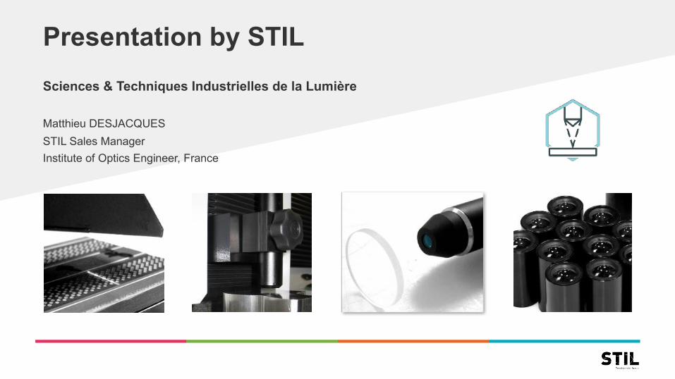
Presentation by STILSciences & Techniques Industrielles de la Lumière
Matthieu DESJACQUESSTIL Sales ManagerInstitute of Optics Engineer, France
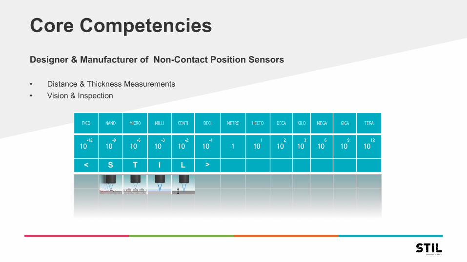
Core CompetenciesDesigner & Manufacturer of Non-Contact Position Sensors
• Distance & Thickness Measurements• Vision & Inspection
PICO NANO MICRO MILLI CENTI DECI METRE HECTO DECA KILO MEGA GIGA TERA
10-12
10-9
10-6
10-3
10-2
10-1
1 101
102
103
106
109
1012
< S T I L >

Sensors Timeline: 25 years of R&D
STIL Awards
• 1997 – Award creative industries
• 2003 – Award technology showcase• 2008 – Silver Photon – Innovation showcase
• 2016 – Créative Industry Nominee
1993STIL creation• 3 PhDs• 300 sqf
2000Staff: 21• 3 PhDs• 8 Engineers• 9 Technicians• 3000 sqf
2007Staff: 30• 3 PhDs• 14 Engineers• 13 Technicians• 7000 sqf
2016Staff: 38• 3 PhDs• 15 Engineers• 20 Technicians• 11 000 sqf
Based in SouthernFrance
2015New ownership
New CEONew strategy
Chromatic Confocal Technology
Point Line
Multipoint Vision
Distance Roughness Thickness
Dimension Inspection Multilayer
Non-contact High- Resolution
Precision Fast Results
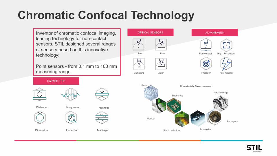
Inventor of chromatic confocal imaging, leading technology for non-contact sensors, STIL designed several ranges of sensors based on this innovative technology:
Point sensors - from 0,1 mm to 100 mm measuring range
OPTICAL SENSORS ADVANTAGES
CAPABILITIESGlass
Medical
Electronics
Semiconductors Automotive
Aerospace
Watchmaking
All materials Measurement

Key product
2005 Creation secondgenerationPoint Sensor(CCS)
1995 Creation firstgenerationPoint Sensor(CHR)
2008Creation firstgenerationLine Sensor(MPLS180)
2016Creation firstMultipoint Sensor(X-DM)
2012Creation firstgenerationVision Sensor(MC2)
From micrometric to nanometricChromatic confocal principle
Ready-made products - Adaptive technology - Proven track record - Plug & play measurement solutions

Technology: Confocal ImagingConfocal imaging consists in:• Imaging a point source S on a sharply-focused
spot S’• Reversely, imaging S’ on a small filtering pinhole
S’’
Features: • 2 optically conjugated pinholes located at points S
and S”• Coaxial imaging
P same light path for illumination and detectionP double crossing of the lens
• “Single point” viewing systemP scanning along X and Y s is required in order to obtain a full-field systemP ‘Optical sectioning’
« Single Point »Viewing System
S’
S
S’’
L
spatial filter
pinhole
pinhole
Light source
Beam splitter
Spot on sample surface
Photodetector
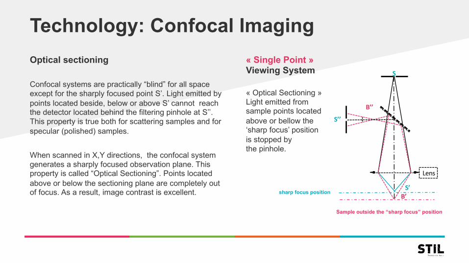
Technology: Confocal ImagingOptical sectioning
Confocal systems are practically “blind” for all spaceexcept for the sharply focused point S’. Light emitted bypoints located beside, below or above S’ cannot reachthe detector located behind the filtering pinhole at S’’. This property is true both for scattering samples and forspecular (polished) samples.
When scanned in X,Y directions, the confocal system generates a sharply focused observation plane. Thisproperty is called “Optical Sectioning”. Points locatedabove or below the sectioning plane are completely out of focus. As a result, image contrast is excellent.
« Single Point »Viewing System
« Optical Sectioning »Light emitted fromsample points locatedabove or bellow the‘sharp focus’ positionis stopped bythe pinhole.
sharp focus position
Sample outside the “sharp focus” position
Lens
S
B’’S’’
S’B’

Technology: Axial chromatismIn a chromatic optical system the position of the image of any given point depends on the wavelength of incident light.Axial Chromatism is a physical property of refractive optical systems, observed for all types of glasses.It results from the spectral dispersion (dependence of the refractive index on wavelength).
In most cases, optical designers workhard to eliminate the axial chromatismwhich is usually considered to be a geometrical aberration of refractiveoptical systems.However, in some very specificapplications, the presence of a controlled amount of chromatism maybe very useful. This is the case of Chromatic Confocal Imaging.A controlled amount of chromatismmay be obtained by carefully selectingthe type of glass and the radii of all thesurfaces in the optical system.
Polychromatic point source
S
l1 l2 ln
Axial distribution of monochromatic images of point S
Chromatic Optical system
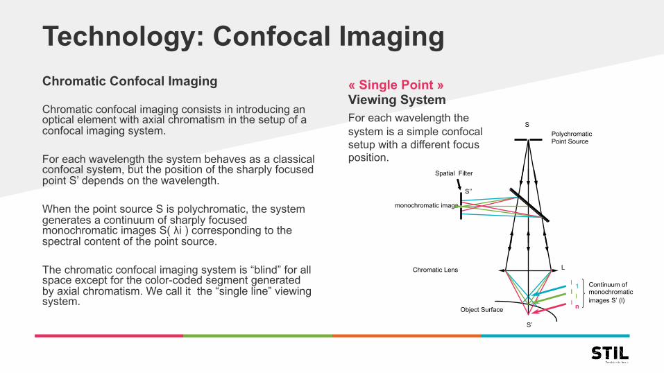
Technology: Confocal ImagingChromatic Confocal Imaging
Chromatic confocal imaging consists in introducing anoptical element with axial chromatism in the setup of a confocal imaging system.
For each wavelength the system behaves as a classicalconfocal system, but the position of the sharply focusedpoint S’ depends on the wavelength.
When the point source S is polychromatic, the system generates a continuum of sharply focusedmonochromatic images S( λi ) corresponding to thespectral content of the point source.
The chromatic confocal imaging system is “blind” for allspace except for the color-coded segment generatedby axial chromatism. We call it the “single line” viewingsystem.
« Single Point »Viewing SystemFor each wavelength thesystem is a simple confocalsetup with a different focus position.
Continuum ofmonochromaticimages S’ (l)
PolychromaticPoint Source
Spatial Filter
monochromatic image
Object Surface
S’’
S’
L
lll
1
nI
S
Chromatic Lens

Technology: Chromatic Confocal ImagingThe Chromatic confocal viewing system presents theunique property of « perfect focus » over all thechromatic extended measuring range
Since at any given point of the axial field of view thereis only one wavelength perfectly focused on the object, all the other wavelengths being inactive.
The Property of ‘Perfect Focus’Multi Confocal Extended depth of focus coded by the‘Rainbow Effect’
L

Technology: Chromatic Confocal Sensors
• Using Chromatic Confocal Imaging for 3D Metrology• Distance measurement consists of 2 steps
COLOR-CODING OF SPACE
By using the axial chromatism of the illuminating beam
COLOR DECODING
By analyzing the spectral content (wavelength) of the beam which has passed through the pinhole

Technology: Chromatic Confocal Sensors
There exist many different means for analyzing the spectral content of the light beam filtered by the pinhole. One of them is the traditional spectrometer, comprising a dispersive element (a grating or a prism) and a line detector.
The position of the spectral peak along the line detector indicates the location of the sample inside the measuringrange.
Color decoding
Incident beam
Dispersive element
Line detector
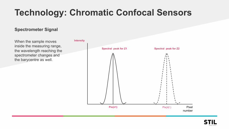
Technology: Chromatic Confocal SensorsSpectrometer Signal
When the sample movesinside the measuring range,the wavelength reaching thespectrometer changes andthe barycentre as well.
Spectral peak for Z1 Spectral peak for Z2
Intensity
Pix(λ2 )Pix(λ1) Pixel number
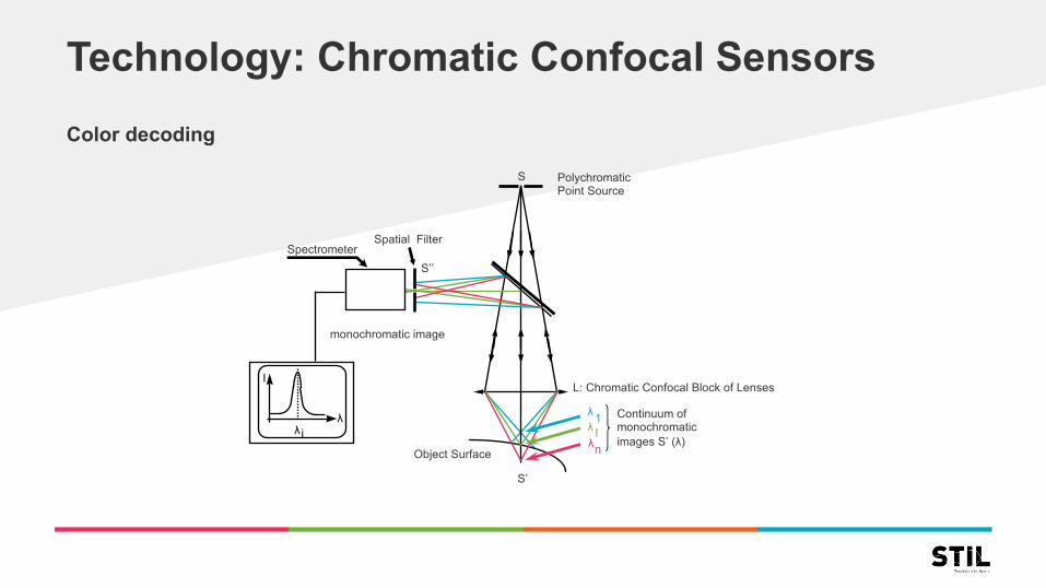
Technology: Chromatic Confocal SensorsColor decoding
Continuum ofmonochromaticimages S’ (λ)
PolychromaticPoint Source
Spatial Filter
monochromatic image
Object Surface
SpectrometerS’’
S’
L: Chromatic Confocal Block of Lenses
λλλ
1
nI
I
λλi
S

TechnologyMeasuring thickness of transparent samples
Multi-layer samplesMeasuring samples comprising several layers is possible using the same method.
As of today, the required computation power exceedsthat of the internal processing unit of our sensors. However this operation can be carried out on the host PC, using our “Multipeak” software. This software canmeasure up to 10 layers simultaneously at real time.
Principle
MultiLayer ‘Thickness’ measuring mode
Polychromatic point source: White Light / IR
White light
λ2λ 1
Spectrometer
λ1λ2S1
S2
3D Topography of each surface
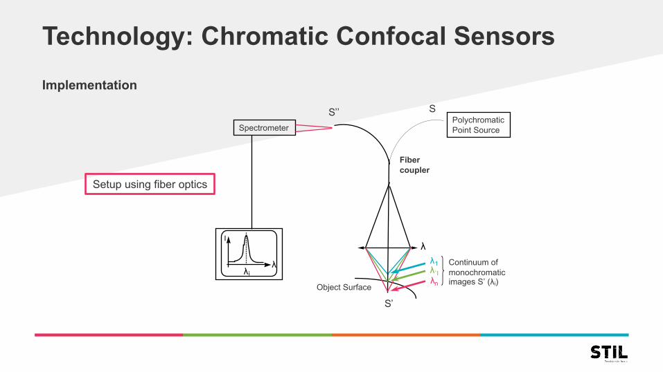
Technology: Chromatic Confocal SensorsImplementation
Continuum ofmonochromaticimages S’ (λi)
PolychromaticPoint Source
Object Surface
S’
λλλλ
1
n`I
I
λλi
S
Spectrometer
S’’
Fiber coupler
Setup using fiber optics

Technology: Chromatic Confocal SensorsSensor layout
Optical fiber cableChromatic lens
Controller
Spectrometer Polychromaticlight source
Digital Signal Processing
Analogical & Digital outputs Fiber optic coupler
Optical pen λ1 λn
Measuring range
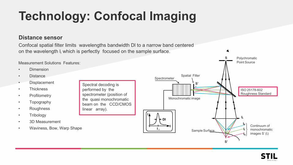
Technology: Confocal ImagingDistance sensorConfocal spatial filter limits wavelengths bandwidth Dl to a narrow band centeredon the wavelength li which is perfectly focused on the sample surface.
Measurement Solutions Features:
• Dimension
• Distance
• Displacement
• Thickness
• Profilometry
• Topography
• Roughness
• Tribology
• 3D Measurement
• Waviness, Bow, Warp Shape
Spectral decoding is performed by thespectrometer (position of the quasi monochromaticbeam on the CCD/CMOS linear array).
Continuum of monochromatic images S’ (li)
PolychromaticPoint Source
Spatial Filter
Monochromatic image
Sample Surface
Spectrometer
S’’
S’
LI
ll i
Dl
S
l0liln
ISO 25178-602Roughness Standard
Technology: Chromatic Confocal Sensors
Axial properties• Measuring range: Directly dependant from the choice of
Chromatic Block of Lenses used.
• Working distance: Distance from the optical pen and the first point of the Measuring Range.
• Accuracy: Along the Measuring Range - No Speckle Effects.
• High Axial resolution: From 7 nanometers (nm) without averaging and 2 nm with avg 10.
Lateral properties• Spot size: Directly dependant of the Pinhole Diameter and
Optical pen Magnification
• Lateral resolution: correspond to half the spot size Diameter – from less than 1 micrometer.
Optical properties• High Numerical Aperture which allows to measure High
slope angle: +/-45° on Mirror and >80° on Diffusive Surfaces.
• Coaxial Beam: No shadow effects.
• Works on Every Kind of Surfaces thanks to theAutoModulation of Light Source Intensity.
• Several ranges of Frequency: From 100Hz to 10 KHz.
Mechanical properties• Optical pens composed of Passive components: Dimensions
from 4mm Diameter and Weight from 15g
• Straight measurement or Radial measurement (90°)
STIL sensors hardware

Technology: Chromatic Confocal SensorsSTIL controllers
• CCS PRIMA: From 100Hz to 2KHz, available with 2 or 4 channels• CCS OPTIMA+: until 10 KHz• STIL VIZIR: InfraRed Light Source, until 2KHz
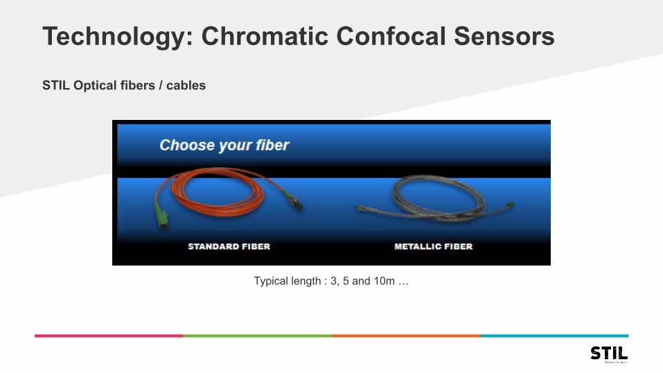
Technology: Chromatic Confocal SensorsSTIL Optical fibers / cables
Typical length : 3, 5 and 10m …
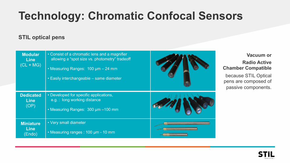
Technology: Chromatic Confocal SensorsSTIL optical pens
Vacuum or Radio Active
Chamber Compatiblebecause STIL Optical
pens are composed of passive components.
Modular Line
(CL + MG)
• Consist of a chromatic lens and a magnifierallowing a “spot size vs. photometry” tradeoff
• Measuring Ranges: 100 µm – 24 mm
• Easily interchangeable – same diameter
DedicatedLine(OP)
• Developed for specific applications, e.g. : long working distance
• Measuring Ranges: 300 µm –100 mm
MiniatureLine
(Endo)
• Very small diameter
• Measuring ranges : 100 µm - 10 mm

Technology: Chromatic Confocal SensorsSTIL CL-MG references (D=27mm)
Model unit CL1-MG210 CL2-MG210 CL3-MG140 CL4-MG35 CL5-MG20 CL6-MG20Measuring range µm 150 400 1400* 4000 12000 24000Working distance mm 3,3 10,8 12,2 16,5 26,6 20
Numerical aperture 0,71 0,46 0,41 0,32 0,2 0,12Max. sample slope ° 42 28 25 21 14 8,5
Reference plate no yes yes yes yes noAxial model standard
90° folded model optionSpot size µm 2,7 4 6,8 12,3 40 43
Lateral resolution µm 1,1 1,7 2,6 4,6 14 18Static noise nm 7 17 50 110 425 800
Max. linearity error nm 25 55 150 300 550 1200Min. measurable thickness µm 7,5 14 38 110 550 725
Length mm 243,8 243,3 208,9 145,4 130 155,6Diameter mm 27Weight g 268 248 215 155 160 180
Technology: Chromatic Confocal Sensors
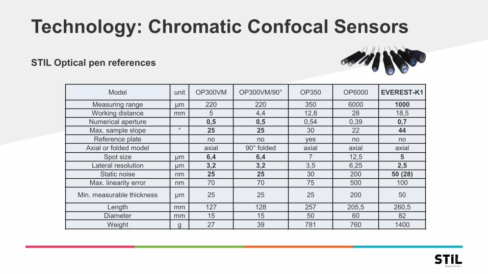
STIL Optical pen references
Model unit OP300VM OP300VM/90° OP350 OP6000 EVEREST-K1
Measuring range µm 220 220 350 6000 1000Working distance mm 5 4,4 12,8 28 18,5
Numerical aperture 0,5 0,5 0,54 0,39 0,7Max. sample slope ° 25 25 30 22 44
Reference plate no no yes no noAxial or folded model axial 90° folded axial axial axial
Spot size µm 6,4 6,4 7 12,5 5Lateral resolution µm 3,2 3,2 3,5 6,25 2,5
Static noise nm 25 25 30 200 50 (28)Max. linearity error nm 70 70 75 500 100
Min. measurable thickness µm 25 25 25 200 50
Length mm 127 128 257 205,5 260,5Diameter mm 15 15 50 60 82Weight g 27 39 781 760 1400

Technology: Chromatic Confocal SensorsSTIL Endo/Probe references
Model unit ENDO 2,0/D4 ENDO 0,1/D6 ENDO 1,5/D6-90 ENDO 0,2/D8 PROBE 10/D8 ENDO 10/D8-90
Measuring range µm 2000 100 1500 200 10000 10000
Working distance mm 5,6 1,1 0,8 4,8 9 5
Numerical aperture 0,12 0,41 0,19 0,39 0,1 0,095
Max. sample slope ° 5 24 10 23 ±4,5 5,4
Axial or radial model axial axial radial axial axial radial
Spot size µm 30 6,25 19,5 4,6 35 41,6
Lateral resolution µm 15 3,2 10 2,3 17,5 21
Static noise nm 300 25 220 30 900 900
Max. linearity error nm 400 45 300 70 1000 1200
Min. measurable thickness µm 500 35 210 25 900 1000
Length mm 53,8 58,9 89,2 67,8 141 87
Diameter mm 4 6 8
Weight g 8 10 12 15 26 20
Technology: Chromatic Confocal Sensors
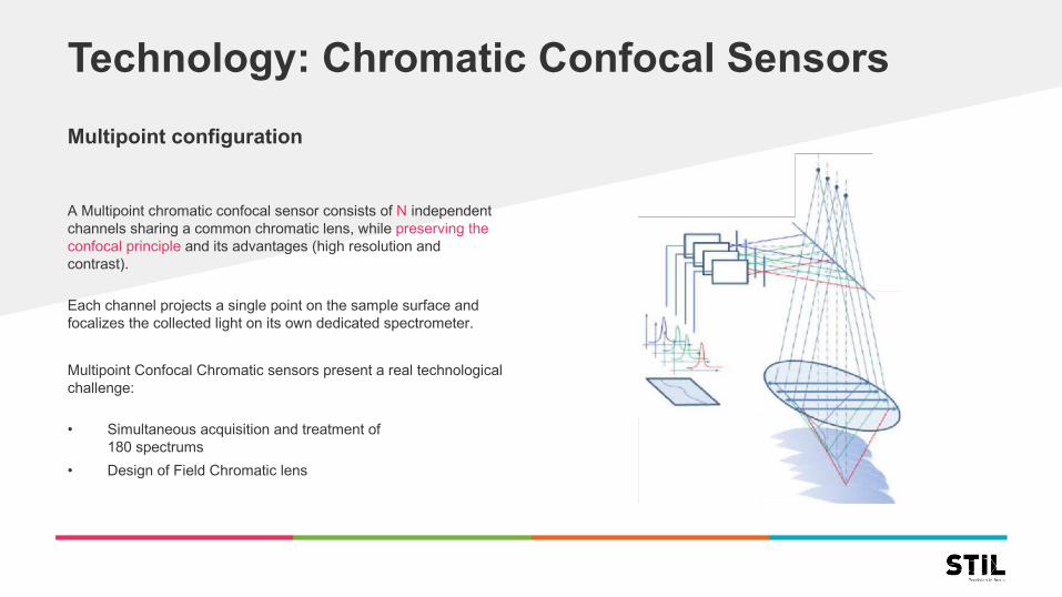
A Multipoint chromatic confocal sensor consists of N independent channels sharing a common chromatic lens, while preserving theconfocal principle and its advantages (high resolution andcontrast).
Each channel projects a single point on the sample surface andfocalizes the collected light on its own dedicated spectrometer.
Multipoint Confocal Chromatic sensors present a real technologicalchallenge:
• Simultaneous acquisition and treatment of180 spectrums
• Design of Field Chromatic lens
Multipoint configuration

Technology: Chromatic Confocal Sensors
STIL multipoint line sensors
Model unit NanoView MicroView DeepView WireViewLine Length mm 1,34 1,79 4,05 1,51
Measuring range 2kHz µm 100 500 2600 900MR 4kHz µm 45* 235* 1150* 450*MR 6kHz µm 25* 120* 650* 240*
Working distance mm 4,6 10,1 47,8 7,8Numerical aperture 0,7 0,5 0,35 0,75Max. sample slope ° 40 30 20 46
Pitch (dist. between 2 points) 7,4 10 22,4 8,4Spot size µm 3,75 5,2 11,5 4,2
Static noise nm 25 100 350 150Max. linearity error nm 50 80 150 100
Min. measurable thickness µm 18 50 300 110Optical Part : Length mm 436,8 425,6 445,9 480,7
Optical Part: Diameter mm 50 50 75 70Optical Part : Weight g 1600 1600 3400 2200

Chromatic Confocal SensorsSTIL multipoint sensors
Up to N independantmeasuring channels
• multiple optical probes(standard)
• multiple points inside thesame optical probe(custom design)

Applications: Chromatic Confocal Sensors
« Single Point »Application ExampleDimension & thickness control onlaminated glass (multiple layers)
THICKNESSAIR GAP
SHAPE
Applications: Chromatic Confocal Sensors
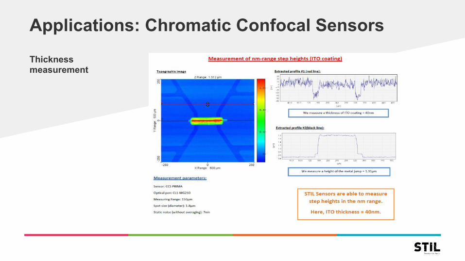
Thicknessmeasurement

Applications: Chromatic Confocal Sensors
« MultiPeak»For multi layer thicknessmeasurement

Chromatic Confocal Camera
If the spectrometer of each individual channel is replaced by a single photon detector, or a single pixel, one gets a system which can see the observed sample point at perfect focus at any axial position inside thedepth of focus.
However this system is unable to determine the axialposition: otherwise stated, one gets a microscope withan extended depth of focus.
STIL Inspection System Principle: AOI
CCD/ CMOS Detector
l1l2l3
Object
Entrance slitx
z

Chromatic Confocal CameraSTIL Chromaline Camera
Model unit NanoView MicroView DeepView WireViewLine Length mm 1,35 1,8 4 1,5
Depth of field µm 100 500 2600 900Working distance mm 4,6 10 47,8 7,8
Magnification 17,3 12,5 5,6 15,6Numerical aperture 0,7 0,5 0,35 0,75Max. sample slope ° 40 30 20 46
Pixel size on the sample µm 0,41 0,56 1,23 0,45Optical Part : Length mm 393,3 382,1 403,9 437,2
Optical Part : Diameter mm 50 50 75 70
• Maximum Frequency Acquisition: More than 100 000 lines/second• Minimum Default Size Inspection: Less than 1 micrometer
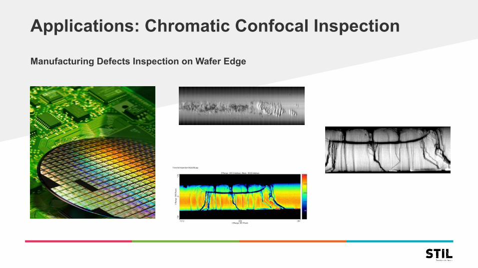
Applications: Chromatic Confocal Inspection
Manufacturing Defects Inspection on Wafer Edge