Development and verification of a novel device for dental ... · scanning using chromatic confocal...
12
Development and verification of a novel device for dental intra-oral 3D scanning using chromatic confocal technology M. Zint*, K. Stock*, R. Graser**, T. Ertl***, E. Brauer*, J. Heyninck***, J. Vanbiervliet ***, S. Dhondt***, Pieter De Ceuninck***, R. Hibst* *Institut für Lasertechnologien in der Medizin und Meßtechnik an der Universität Ulm, **Cubert GmbH, ***Dentsply International ABSTRACT The presented work describes the development and verification of a novel optical, powder-free intra-oral scanner based on chromatic confocal technology combined with a multifocal approach. The proof of concept for a chromatic confocal area scanner for intra-oral scanning is given. Several prototype scanners passed a verification process showing an average accuracy (distance deviation on flat surfaces) of less than 31μm ± 21μm and a reproducibility of less than 4μm ± 3μm. Compared to a tactile measurement on a full jaw model fitted with 4mm ceramic spheres the measured average distance deviation between the spheres was 49μm ± 12μm for scans of up to 8 teeth (3- unit bridge, single Quadrant) and 104μm ± 82μm for larger scans and full jaws. The average deviation of the measured sphere diameter compared to the tactile measurement was 27μm ± 14μm. Compared to μCT scans of plaster models equipped with human teeth the average standard deviation on up to 3 units was less than 55μm ± 49μm whereas the reproducibility of the scans was better than 22μm ± 10μm. Keywords: Intra-oral scanning, chromatic-confocal technology, optical inspection, optical metrology, portable optical 3D inspection 1. INTRODUCTION As depicted in Figure 1 the conventional process of impression taking requires many steps to finally get to the restoration which is cemented in the patient’s mouth. It is easy to understand that between all these steps many sources for possible errors are hidden 1 . The first step towards digital dentistry is already well established by scanning the plaster models which originated from the conventional impression and to manufacture the restorations with an automated computer aided manufacturing process (CAD/CAM). Since the conventional impression taking has many sources for errors, has a significant discomfort for the patients and the CAD/CAM process is already well established a logical consequence of this development is to substitute the conventional process by an intraoral scan directly taken inside the patients mouth. The use of optical intra-oral scanners (IO-scanners) is on the rise and will play a significant role in the future of dentistry. In the year 2005 only two IO-scanners were commercially available, whereas on the IDS 2013 over 12 devices were shown. Many of the available IO-scanners require a TiO 2 powder coating on the teeth to attain a good scanning result because human tooth is a bulk scattering material 2 and also highly reflective surfaces like gold fillings occur in a patients mouth. Also scanners which require a coating are quite successful and accepted, those working without coating are more comfortable for the patient as well as for the dentist 3 and do not introduce the problem of an unknown coating thickness which might result in an incorrect measurement. Confocal imaging technique can solve this problem, but usually requires either moving mechanical parts for a z-scan (monochromatic) and means for lateral positioning of the probe or specimen (single point chromatic confocal technique). Both approaches are disadvantageous regarding scanning speed, accuracy and reliability. Within the scope of industry sponsored research activity the Institute for Laser-Technologies in medicine and metrology at the University of Ulm (ILM) developed a novel IO-scanner based on the chromatic confocal distance measurement with the aim to perform fast an accurate scans on human teeth without the use for any coating.
Transcript of Development and verification of a novel device for dental ... · scanning using chromatic confocal...
Development and verification of a novel device for dental intra-oral 3D
scanning using chromatic confocal technology
M. Zint*, K. Stock*, R. Graser**, T. Ertl***, E. Brauer*, J. Heyninck***, J. Vanbiervliet ***, S. Dhondt***,
Pieter De Ceuninck***, R. Hibst*
*Institut für Lasertechnologien in der Medizin und Meßtechnik an der Universität Ulm, **Cubert GmbH, ***Dentsply
International
ABSTRACT
The presented work describes the development and verification of a novel optical, powder-free intra-oral scanner based
on chromatic confocal technology combined with a multifocal approach. The proof of concept for a chromatic confocal
area scanner for intra-oral scanning is given. Several prototype scanners passed a verification process showing an
average accuracy (distance deviation on flat surfaces) of less than 31µm ± 21µm and a reproducibility of less than 4µm ±
3µm. Compared to a tactile measurement on a full jaw model fitted with 4mm ceramic spheres the measured average
distance deviation between the spheres was 49µm ± 12µm for scans of up to 8 teeth (3- unit bridge, single Quadrant) and
104µm ± 82µm for larger scans and full jaws. The average deviation of the measured sphere diameter compared to the
tactile measurement was 27µm ± 14µm. Compared to µCT scans of plaster models equipped with human teeth the
average standard deviation on up to 3 units was less than 55µm ± 49µm whereas the reproducibility of the scans was
better than 22µm ± 10µm.
Keywords: Intra-oral scanning, chromatic-confocal technology, optical inspection, optical metrology, portable optical
3D inspection
1. INTRODUCTION
As depicted in Figure 1 the conventional process of impression taking requires many steps to finally get to the restoration
which is cemented in the patient’s mouth. It is easy to understand that between all these steps many sources for possible
errors are hidden1. The first step towards digital dentistry is already well established by scanning the plaster models
which originated from the conventional impression and to manufacture the restorations with an automated computer
aided manufacturing process (CAD/CAM). Since the conventional impression taking has many sources for errors, has a
significant discomfort for the patients and the CAD/CAM process is already well established a logical consequence of
this development is to substitute the conventional process by an intraoral scan directly taken inside the patients mouth.
The use of optical intra-oral scanners (IO-scanners) is on the rise and will play a significant role in the future of dentistry.
In the year 2005 only two IO-scanners were commercially available, whereas on the IDS 2013 over 12 devices were
shown. Many of the available IO-scanners require a TiO2 powder coating on the teeth to attain a good scanning result
because human tooth is a bulk scattering material2 and also highly reflective surfaces like gold fillings occur in a patients
mouth. Also scanners which require a coating are quite successful and accepted, those working without coating are more
comfortable for the patient as well as for the dentist3 and do not introduce the problem of an unknown coating thickness
which might result in an incorrect measurement.
Confocal imaging technique can solve this problem, but usually requires either moving mechanical parts for a z-scan
(monochromatic) and means for lateral positioning of the probe or specimen (single point chromatic confocal technique).
Both approaches are disadvantageous regarding scanning speed, accuracy and reliability.
Within the scope of industry sponsored research activity the Institute for Laser-Technologies in medicine and metrology
at the University of Ulm (ILM) developed a novel IO-scanner based on the chromatic confocal distance measurement
with the aim to perform fast an accurate scans on human teeth without the use for any coating.

Figure 1. Work flow of conventional and digital process of impression taking 1
2. MATERIALS AND METHODOLOGY
2.1 The chromatic confocal principle
Sensors based on the confocal principle are well established in various applications in industrial metrology. Manifold
systems are available ranging from single point sensors to line or even area sensors4. An easy way of using the confocal
principle is using monochromatic light while other sensors already use polychromatic light to obtain a wavelength coded
distance measurement. The currently available scanners are used for industrial topography measurement in the
micrometer or nanometer range, e.g. for roughness characterization, thickness measurements (transparent media) and are
often combined with positioning systems, like coordinate measurement machines, to either move the specimen or the
sensor.
If monochromatic light is used the system has a single distance Z at which the signal is at maximum intensity. In order to
capture the surface of an object it is therefore necessary to move the specimen or the sensor (or single parts of it) in axial
direction and record the movement to acquire the correct distance between the object and the sensor. Although very
precise measurements are possible usually this type of measurement is rather time consuming for 3D scanning of whole
areas since the axial scanning has to be repeated at every single point within the area of interest. To reduce the
measurement time some devices use multifocal approaches, but the necessity to move mechanical and optical parts is
still remaining.
In order to avoid the mechanical movement polychromatic light can be used. As shown in Figure 2 a lens with a high
axial chromatic focus shift (hyperchromatic lens) can be implemented to image a focus of white light onto the specimen.
The hyperchromatic lens spectrally spreads the light in axial direction while maintaining a good image quality for each
wavelength at different distances with respect to the sensor. Depending on the distance between the specimen and the
sensor a specific wavelength is sharply imaged, whereas all other wavelengths are out of focus. The reflected light
returns back into the hyperchromatic lens and passes a beam splitter. After the beam splitter the reflected light has to
pass a pinhole which is located at an optical conjugate position to the origin of the initial focus of white light. As a result
the specific wavelength shows a significant higher intensity at the pinhole in comparison to all other wavelength. This
wavelength can easily be determined by using a spectrometer. Once the correlation between the wavelength and the
distance is calibrated the sensor is able to measure distances without the need to move any mechanical or optical part.
This type of sensors are well known for single point measurements with the need to move the sensors in defined lateral
steps in order to capture the surface of a specimen.

Figure 2. Basic principle of the novel chromatic confocal distance measurement.
Although these single point sensors showed goods results acquiring 3D data on human teeth they are not applicable for
intra-oral scanning. It is to be expected that single point measurements acquired by manual movement of the sensor in a
patient’s mouth can hardly be combined to an accurate surface representation. Furthermore means of defined sensor
movement would result in a bulky device and are likely to be corrupted by the patient’s movements.
For this reason an enhanced system concept was elaborated allowing miniaturization of the device and providing
increased scan speed. Instead of using a single focus of white light and a single pinhole a micro lens array and a pinhole
array were introduced (Figure 2). The idea behind this approach is that a whole set of measurements can be taken at one
time resulting in the fact that each dataset contains the surface representation at full axial resolution a sufficient lateral
resolution to fit consecutive datasets onto each other (surface registration). Another advantage is that the system is very
robust against movement artifacts since each measurement point of one dataset encounters the same movement. For this
reason the point cloud of one dataset taken within a time period of less than 30ms does not show any distortions
introduced by movement of either the wand or the patient. Specific challenges of this approach are the efficient use of
the detector space, adequate handling of stray light and cross talk between the different channels. Moreover sophisticated
customized optics were designed to maintain good imaging quality over the whole object height since commercially
available lens systems would not comply with the specific requirements.
2.2 Laboratory setup I
Prior the final system design and development a first laboratory setup (Figure 3) was realized comprising of a
customized hyperchromatic lens, a spectrometer build up with optical stock components, a commercially available
camera using a SONY CCD chip (ICX039DLA) and a medical XE light source. The multifocal illumination pattern was
generated using a SUSS micro lens array and in the detection path a single pinhole of a few microns in size was
positioned. To establish the confocal condition the micro lens array and the pinhole array are each fitted to adjustment
frames and the pinhole position was matched with a single focus of the micro lens array. With this setup a multifocal
illumination of the specimen with single point detection was possible. By matching of the pinhole to different foci of the
micro lens array the performance and effects at different filed heights of the optics were investigated. Cross sections of
specimens can be recorded by defined moving the specimen.

Figure 3. First laboratory setup of the IO-Scanner.
2.3 Prototype of the IO-Scanner
After the proof of concept was given with the first laboratory setup a refined system concept was elaborated. In the first
step the whole optical concept was redesigned using the optical design Software ZEMAX®
. A compact optical design for
the hyperchromatic lens was achieved allowing the imaging of a two dimensional illumination pattern with over 1000
measuring spots. The size of the hyperchromatic lens is optimized in the manner that an easy maneuvering inside the
patient’s mouth is possible and the light beam is folded by 90° to get access also at the distal teeth. The exemplary spot
diagram in Figure 4 shows that an excellent (almost diffraction limited) imaging quality was achieved throughout a field
height of more than 5x5mm² while simultaneously maximizing the axial chromatic focus shift for each measurements
point to greater than 10mm. For better interproximal coverage the ray path was kept telecentric resulting in an even more
challenging design.
Figure 4. Exemplary spot diagram of the hyperchromatic lens for one wavelength
Similar to the hyperchromatic lens a customized optics for the detection system (multiline spectrometer) was designed.
This optic was designed to image a two dimensional pinhole array with over 1000 holes of a few microns in size onto an
detector array (e.g. CCD Sensor). A further challenge regarding this design was to provide sufficient and equal spectral
Xe- Light source
+ optical fiber
multiline spectrometer
hyperchromat
specimen
confocal unit
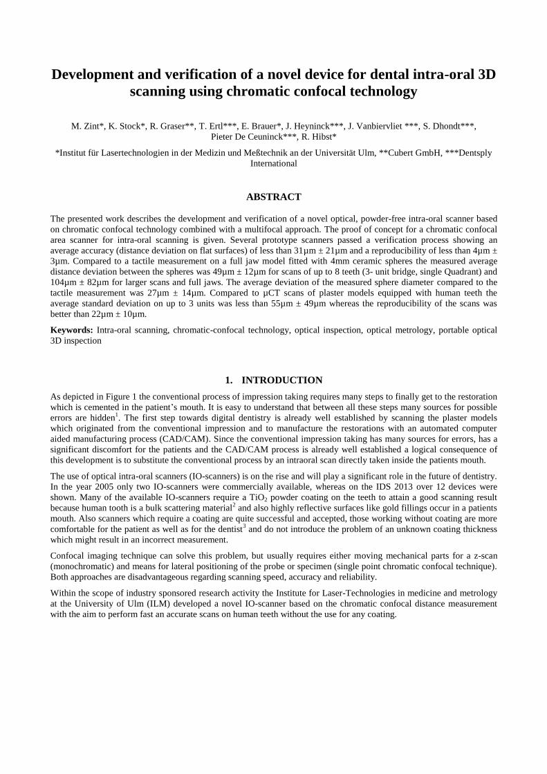
dispersion for each measuring point to obtain the required resolution in Z. The need for clearly separated channels for the
spectral signals on the detector demand excellent imaging quality (almost diffraction limited) over the whole field height
which is exemplary shown in Figure 5 for one wavelength.
Figure 5. Exemplary spot diagram of the multiline spectrometer
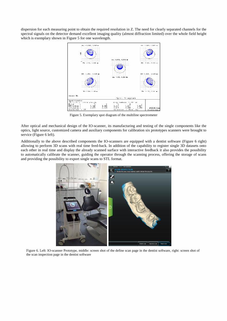
After optical and mechanical design of the IO-scanner, its manufacturing and testing of the single components like the
optics, light source, customized camera and auxiliary components for calibration six prototypes scanners were brought to
service (Figure 6 left).
Additionally to the above described components the IO-scanners are equipped with a dentist software (Figure 6 right)
allowing to perform 3D scans with real time feed-back. In addition of the capability to register single 3D datasets onto
each other in real time and display the already scanned surface with interactive feedback it also provides the possibility
to automatically calibrate the scanner, guiding the operator through the scanning process, offering the storage of scans
and providing the possibility to export single scans to STL format.
Figure 6. Left: IO-scanner Prototype, middle: screen shot of the define scan page in the dentist software, right: screen shot of
the scan inspection page in the dentist software

2.4 Conditions for static tests with the prototypes
The attainable accuracy of the 3D scans produced with the developed IO-Scanner depends on several conditions such as
the chosen scan path, the macroscopic surface topology and the material. In case of human teeth tests have shown that
scanning dry teeth is much easier than scanning wet teeth and the effect of dehydration is noticeable already within
minutes. In order to avoid evaluate the scanner performances and variation among scanners in a defined and repeatable
way the first approach was to evaluate the accuracy and repeatability on two different flat targets with stable optical
properties. The first target used is a flat aluminum coated mirror with a surface quality of 1/10 whereas the second
target was the bright side of a Vita Triluxe Block (A2), polished with 4000 SIC sandpaper. The use of a second target
was done to capture eventual influences of bulk scattering material regarding the scan performance. The tests on the flat
targets followed a specified protocol:
Scanner is mounted in a stable position onto a table which is mechanically decoupled from the building (e.g.
passive decoupled optical table)
The scan target is mounted onto the positioning system (SmarAct piezo positioning system SLC-1740-S-HV)
The positioning system is placed in such a manner that the scan target can be positioned in any height location
within the scan range of the scanner under test
The angulation of the positioning system together with the target is adjusted in such manner that the target
surface is orthogonal towards the optical axis of the measuring light beam (using a manual tilt stage)
A preconfigured testing software is started
After the test is prepared like described the piezo drives the flat target to defined axial positions inside the measurement
range of the scanner. At each position 100 raw data measurements are taken. One measurement of each height was taken
for calibration of the scanner. The remaining raw data was taken to calculate the measured height values like it would be
done during real time measurement. Finally a statistical analysis regarding the measured values was applied.
A scanner was specified to be good if the total number of calibrated points was greater than 1000, the average height
deviation towards the true distance of all measurements points’ at all evaluated heights was less than 30µm (accuracy)
and the mean standard deviation of all measured values at all heights was less than 4µm (precision).
2.5 Conditions of 3D Scans with the prototypes and evaluation
After calibration and successful pass of the static test the scanner prototypes allow a video like capturing of the specimen
by either moving the wand over the specimen or vice versa.
“Natural tooth model”
Figure 7. Full arc scan of a plaster model partly equipped with human teeth (human teeth are located inside the black boxes;
teeth 24, 26, 27, 28 17, 18)
First 3D scans with the IO-Scanner were done by scanning a plaster model which was partly equipped at with natural
human teeth at the positions 24, 26, 27, 28 17, 18 (“natural tooth model”; see Figure 7). The model was also send to a
certified scan lab and recorded using a Zeiss Metrotom 1500 μCT scanner which provides an accuracy of about 10µm
according to manufacturer information. The model was stored in water and only taken out for scanning to keep the
optical properties of the teeth as realistic as possible. Before the scans were performed fluid retentions were wiped off
with a towel to avoid measuring the surface of the liquid. The scans were performed by fixating the scanner with a clamp
and moving the tooth model. The scans were repeated between 5 to 12 times for tooth rows and single teeth. The STL
files of the scans were imported into Geomagic Qualify 12 and an average surface model was created out of the scan
data. The average surface model was compared to the individual scans and the average deviation was recorded. In a
second step the averaged model was compared to the µCT scan data and the average deviation was evaluated.
Epoxide resin tooth model
As already mentioned it is very difficult to take reproducible recordings on human teeth since they change their optical
properties over time. For this reason ILM developed a test model with stable optical properties which could be used for
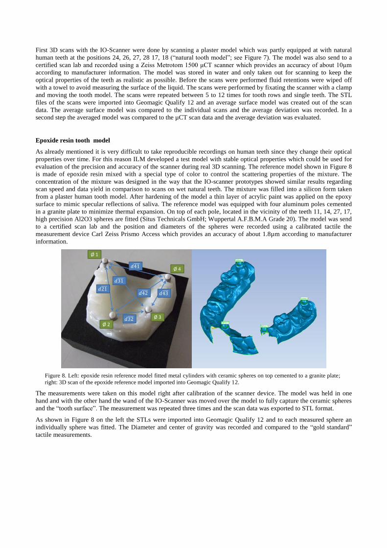
evaluation of the precision and accuracy of the scanner during real 3D scanning. The reference model shown in Figure 8
is made of epoxide resin mixed with a special type of color to control the scattering properties of the mixture. The
concentration of the mixture was designed in the way that the IO-scanner prototypes showed similar results regarding
scan speed and data yield in comparison to scans on wet natural teeth. The mixture was filled into a silicon form taken
from a plaster human tooth model. After hardening of the model a thin layer of acrylic paint was applied on the epoxy
surface to mimic specular reflections of saliva. The reference model was equipped with four aluminum poles cemented
in a granite plate to minimize thermal expansion. On top of each pole, located in the vicinity of the teeth 11, 14, 27, 17,
high precision Al2O3 spheres are fitted (Situs Technicals GmbH; Wuppertal A.F.B.M.A Grade 20). The model was send
to a certified scan lab and the position and diameters of the spheres were recorded using a calibrated tactile the
measurement device Carl Zeiss Prismo Access which provides an accuracy of about 1.8µm according to manufacturer
information.
Figure 8. Left: epoxide resin reference model fitted metal cylinders with ceramic spheres on top cemented to a granite plate;
right: 3D scan of the epoxide reference model imported into Geomagic Qualify 12.
The measurements were taken on this model right after calibration of the scanner device. The model was held in one
hand and with the other hand the wand of the IO-Scanner was moved over the model to fully capture the ceramic spheres
and the “tooth surface”. The measurement was repeated three times and the scan data was exported to STL format.
As shown in Figure 8 on the left the STLs were imported into Geomagic Qualify 12 and to each measured sphere an
individually sphere was fitted. The Diameter and center of gravity was recorded and compared to the “gold standard”
tactile measurements.
3. RESULTS
3.1 Test with the laboratory setup I
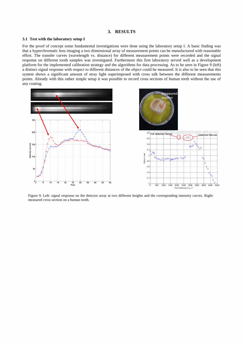
For the proof of concept some fundamental investigations were done using the laboratory setup I. A basic finding was
that a hyperchromatic lens imaging a two dimensional array of measurement points can be manufactured with reasonable
effort. The transfer curves (wavelength vs. distance) for different measurement points were recorded and the signal
response on different tooth samples was investigated. Furthermore this first laboratory served well as a development
platform for the implemented calibration strategy and the algorithms for data processing. As to be seen in Figure 9 (left)
a distinct signal response with respect to different distances of the object could be measured. It is also to be seen that this
system shows a significant amount of stray light superimposed with cross talk between the different measurements
points. Already with this rather simple setup it was possible to record cross sections of human teeth without the use of
any coating.
Figure 9. Left: signal response on the detector array at two different heights and the corresponding intensity curves. Right:
measured cross section on a human tooth.
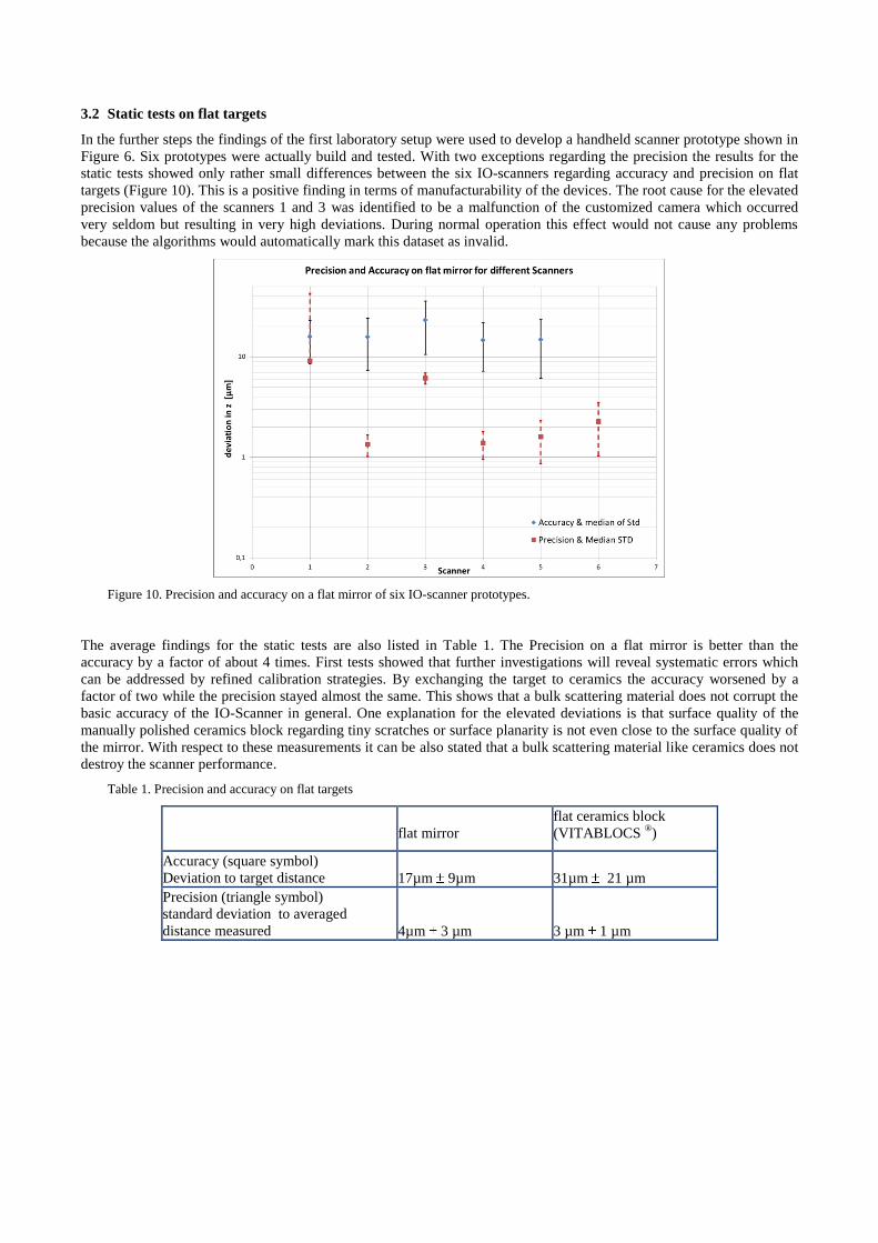
3.2 Static tests on flat targets
In the further steps the findings of the first laboratory setup were used to develop a handheld scanner prototype shown in
Figure 6. Six prototypes were actually build and tested. With two exceptions regarding the precision the results for the
static tests showed only rather small differences between the six IO-scanners regarding accuracy and precision on flat
targets (Figure 10). This is a positive finding in terms of manufacturability of the devices. The root cause for the elevated
precision values of the scanners 1 and 3 was identified to be a malfunction of the customized camera which occurred
very seldom but resulting in very high deviations. During normal operation this effect would not cause any problems
because the algorithms would automatically mark this dataset as invalid.
Figure 10. Precision and accuracy on a flat mirror of six IO-scanner prototypes.
The average findings for the static tests are also listed in Table 1. The Precision on a flat mirror is better than the
accuracy by a factor of about 4 times. First tests showed that further investigations will reveal systematic errors which
can be addressed by refined calibration strategies. By exchanging the target to ceramics the accuracy worsened by a
factor of two while the precision stayed almost the same. This shows that a bulk scattering material does not corrupt the
basic accuracy of the IO-Scanner in general. One explanation for the elevated deviations is that surface quality of the
manually polished ceramics block regarding tiny scratches or surface planarity is not even close to the surface quality of
the mirror. With respect to these measurements it can be also stated that a bulk scattering material like ceramics does not
destroy the scanner performance.
Table 1. Precision and accuracy on flat targets
flat mirror
flat ceramics block
(VITABLOCS ®)
Accuracy (square symbol)
Deviation to target distance 17µm 9µm 31µm 21 µm
Precision (triangle symbol)
standard deviation to averaged
distance measured 4µm 3 µm 3 µm 1 µm

3.3 3D Scans on “natural tooth model”
Figure 11. 3D comparison between the scan on natural teeth cemented into a plaster model (“natural tooth model”) and a
µCT reference dataset (ZEISS Metrotom 1500).
In addition to the static tests several scans on a “natural tooth model” were done. Table 1 shows that the average
accuracy of scans on natural teeth for up to 3 unit bridges or tooth rows with 3 teeth is lower than 55µm 49µm. For
single teeth the accuracy with less than 26µm 20µm was much better. Similar to the static tests the precision of the
scan data is about 2 to 4 times better as the accuracy.
Table 2. Precision and accuracy of 3D scans on plaster model partly equipped with human teeth
Precision [µm] Accuracy [µm]
Average deviation vs.
averaged 3D scan
Standard deviation of averaged 3D
scan vs. reference µCT
Precision on a 3 unit bridge with
natural teeth 22 10 40 51
Precision on a tooth row (3 teeth) 13 3 55 49
Precision on single natural teeth 6 1 26 20

3.4 3D Scans on an epoxide resin tooth model
The final testing of a single prototype was done scanning the epoxide tooth model with ceramic spheres. This test is a quite
strong indicator regarding the achievable accuracy under real conditions. Table 3 shows the deviations of the measured distances
between the spheres with respect to the tactile measurement. Expectedly the deviation becomes greater the farther the spheres are
located from each other. This can easily be explained by the registration errors which accumulate from dataset to dataset and
influences the local accuracy of the IO-scanner. Whereas the achieved accuracy for situations up to 8 units (one quadrant) is rated
good the accuracy over a full jaw scan can 200µm depending on the clinical situation. The local accuracy of the IO-scanner can
be derived from the findings made on the measured sphere diameters. With a mean deviation of less than 27µm 14µm it is in
the same order as the accuracy achieved on single natural teeth and therefore confirms the local accuracy of the scanner.
Table 3. Deviation of measured distances between ceramic spheres fitted to a full jaw tooth model in comparison to tactile
measurement
Distance type true distance [mm] deviation [µm]
d21 Quadrant 2 (8-units) 48.88 62
d31 ¾ jaw 54.81 172
d41 Full jaw 50.05 253
d32 „3 unit bridge“ 23.03 31
d42 Quadrant 1 (8-units) 48.09 56
d43 „3 unit bridge“ 30.41 46
Average Deviation [µm] 104 82
Average Deviation [µm]
possible indications (up to 8 units) 49 12
4. CONCLUSIONS
The here presented work shows the proof of concept for a successful implementation of the multifocal chromatic
confocal area measurement in a handheld IO-Scanner for dentistry. The optical design comprises of a telecentric
hyperchromatic lens providing a field of view greater than 10mm², additionally providing a longitudinal chromatic focal
shift of more than 10mm and a detection system for analyzing more than 1000 data points in parallel. A single picture of
the device delivers 3D data within a volume of more than 1cm³ with full depth resolution. The prototype IO-scanner
allows fast video-like intra-oral capturing (>30fps) of human teeth and tissue without the need for any coating. Beside
the real time data registration of individual 3D datasets taken at different views without any additional position
information the software provides an interactive feedback to the dentist and allows exporting the data to an open STL
format.
The actual local accuracy of the tested IO-scanners on flat surfaces (31µm 21µm) and on single ceramic spheres
(27µm 14µm) is equivalent. These findings are in accordance with the accuracy evaluated on single natural teeth
(26µm 20µm). With 3µm 1µm the precision is significantly better. Taking into account that the fitting accuracy of
the conventional process in best case is about 50µm1 the currently achieved accuracy of less than 55µm 49µm for 3
units and less than 26µm 20µm on single teeth is already quite promising for restorations build on the basis of this
data. The same statement is true with respect to the findings made by comparing measured distances between ceramic
spheres to a tactile reference measurement for up to 8 units (49µm 12µm). According to investigations regarding the
Cerec 3D camera of R.G. Luthard 5 which showed a local accuracy of about 27,9µm on plaster models the presented
accuracy of our Prototype is already comparable. Some theoretical considerations request a marginal gap of less than
50µm6 or even 25µm
7. However with respect to other more clinical oriented recommendations saying that even marginal
gaps between 100-200µm8 are acceptable the current performance of the IO-scanners for up to 8 units seems to be more
than sufficient.

The high precision of the IO-Scanner compared to its accuracy gives the potential for significant improvement by an
enhanced calibration strategy. In the current status the concept of the developed IO-Scanner prototype is very promising
but needs some refinement until it is finally introduced as a new product to the dentist.
ACKNOWLEDGEMENTS
We would like to thank the whole project team of the Dentsply International and Degudent GmbH, especially A. Lichkus
for supporting this research for many years, the commitment to our work and the very good cooperation. Furthermore we
thank A. Wlodarski and C. Koch, from POG for revision and realization of the optical concept for the scanner wand.
Many thanks also W. Henning for the light source development and to the software and electronics development team
around M. Harrieder and L. Kulzer. Without several colleagues of ILM and especially R. Michels, A. Kienle, A. Konz,
R. Diebolder the development would not have been successful.
REFERENCES
[1] Marxkors, R., [Lehrbuch der zahnärztlichen Prothetik] , Deutscher Ärzteverlag, 329 (2007).
[2] Kienle, A., and Hibst, R., “Light guiding in biological tissue due to scattering,” Physical Review
Letters 97(July), 2–5 (2006).
[3] Barfuss, A., “Digitale Abformung versus konventionelle Abformung,” Dent. Mag., 2014,
<http://www.dentalmagazin.de/praxiszahnmedizin/cad-cam/Digitale-Abformung-versus-
konventionelle-Abformung_257266.html> (25 November 2014).
[4] Sackewitz, M., [Leitfaden zur optischen 3D-Messtechnik] , Fraunhofer Verlag, 111 (2014).
[5] Luthardt, R.G., Loos, R., and Quaas, S., “Genauigkeit intraoraler Datenerfassung im Vergleich zur
konventionellen Abformung Accuracy of Intraoral Data Acquisition in Comparison to the
Conventional Impression,” International journal of computerized dentistry 8, 283–294 (2005).
[6] Rehberg, H., “Der Kronenrand: Exakter Randschluß-was ist das,” Dtsch Zahnärztl (1971).
[7] Weikart, P., “Grenzen und Prüfung der Gußgenauigkeit,” Dtsch Zahnärztl (1957).
[8] Kerschbaum, T., “Normierter Kronenrand?-Eine Analyse aus klinischer Sicht,” … in der
Zahnheilkunde. Anspruch und Wirklichkeit, W. …19–45 (1995).


![Komik Under 18 - Zint [H-S]](https://static.fdocuments.net/doc/165x107/551c30554a795909108b47af/komik-under-18-zint-h-s.jpg)