µchiller 3 - CAREL
81
μchiller 3 ENG User manual
Transcript of µchiller 3 - CAREL

µchiller 3
ENG User manual
We wish to save you time and money! We can assure you that the thorough reading of this manual will guarantee correct installation and safe use of the product described.
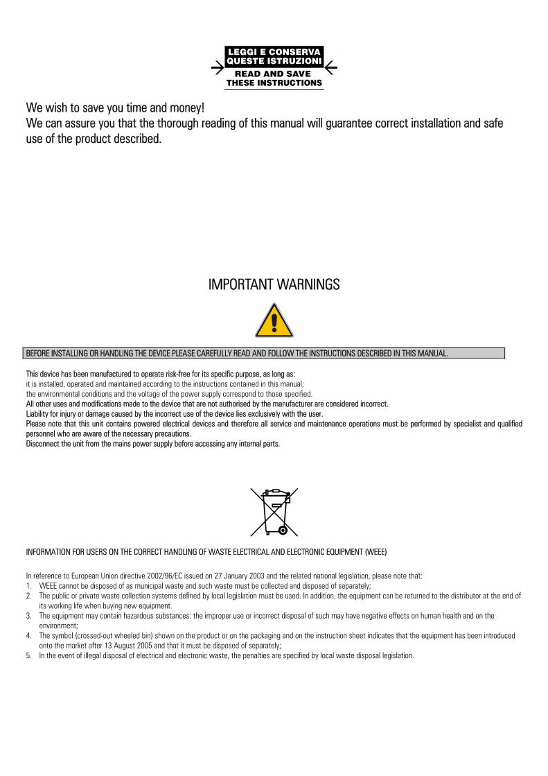
IMPORTANT WARNINGS
BEFORE INSTALLING OR HANDLING THE DEVICE PLEASE CAREFULLY READ AND FOLLOW THE INSTRUCTIONS DESCRIBED IN THIS MANUAL. This device has been manufactured to operate risk-free for its specific purpose, as long as: it is installed, operated and maintained according to the instructions contained in this manual; the environmental conditions and the voltage of the power supply correspond to those specified. All other uses and modifications made to the device that are not authorised by the manufacturer are considered incorrect. Liability for injury or damage caused by the incorrect use of the device lies exclusively with the user. Please note that this unit contains powered electrical devices and therefore all service and maintenance operations must be performed by specialist and qualified personnel who are aware of the necessary precautions. Disconnect the unit from the mains power supply before accessing any internal parts.
INFORMATION FOR USERS ON THE CORRECT HANDLING OF WASTE ELECTRICAL AND ELECTRONIC EQUIPMENT (WEEE) In reference to European Union directive 2002/96/EC issued on 27 January 2003 and the related national legislation, please note that: 1. WEEE cannot be disposed of as municipal waste and such waste must be collected and disposed of separately; 2. The public or private waste collection systems defined by local legislation must be used. In addition, the equipment can be returned to the distributor at the end of
its working life when buying new equipment. 3. The equipment may contain hazardous substances: the improper use or incorrect disposal of such may have negative effects on human health and on the
environment; 4. The symbol (crossed-out wheeled bin) shown on the product or on the packaging and on the instruction sheet indicates that the equipment has been introduced
onto the market after 13 August 2005 and that it must be disposed of separately; 5. In the event of illegal disposal of electrical and electronic waste, the penalties are specified by local waste disposal legislation.
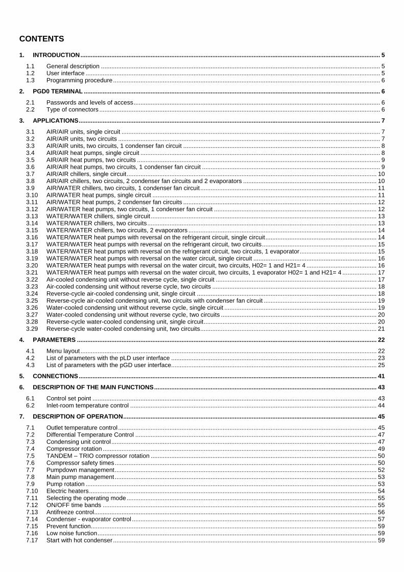
CONTENTS
1. INTRODUCTION ............................................................................................................................................................................... 5 1.1 General description ................................................................................................................................................................... 5 1.2 User interface ............................................................................................................................................................................ 5 1.3 Programming procedure ............................................................................................................................................................ 6
2. PGD0 TERMINAL ............................................................................................................................................................................. 6 2.1 Passwords and levels of access ................................................................................................................................................ 6 2.2 Type of connectors .................................................................................................................................................................... 6
3. APPLICATIONS ................................................................................................................................................................................ 7 3.1 AIR/AIR units, single circuit ....................................................................................................................................................... 7 3.2 AIR/AIR units, two circuits ......................................................................................................................................................... 7 3.3 AIR/AIR units, two circuits, 1 condenser fan circuit ................................................................................................................... 8 3.4 AIR/AIR heat pumps, single circuit ............................................................................................................................................ 8 3.5 AIR/AIR heat pumps, two circuits .............................................................................................................................................. 9 3.6 AIR/AIR heat pumps, two circuits, 1 condenser fan circuit ........................................................................................................ 9 3.7 AIR/AIR chillers, single circuit .................................................................................................................................................. 10 3.8 AIR/AIR chillers, two circuits, 2 condenser fan circuits and 2 evaporators .............................................................................. 10 3.9 AIR/WATER chillers, two circuits, 1 condenser fan circuit ....................................................................................................... 11 3.10 AIR/WATER heat pumps, single circuit ................................................................................................................................... 11 3.11 AIR/WATER heat pumps, 2 condenser fan circuits ................................................................................................................. 12 3.12 AIR/WATER heat pumps, two circuits, 1 condenser fan circuit ............................................................................................... 12 3.13 WATER/WATER chillers, single circuit .................................................................................................................................... 13 3.14 WATER/WATER chillers, two circuits ...................................................................................................................................... 13 3.15 WATER/WATER chillers, two circuits, 2 evaporators .............................................................................................................. 14 3.16 WATER/WATER heat pumps with reversal on the refrigerant circuit, single circuit ................................................................. 14 3.17 WATER/WATER heat pumps with reversal on the refrigerant circuit, two circuits ................................................................... 15 3.18 WATER/WATER heat pumps with reversal on the refrigerant circuit, two circuits, 1 evaporator ............................................. 15 3.19 WATER/WATER heat pumps with reversal on the water circuit, single circuit ........................................................................ 16 3.20 WATER/WATER heat pumps with reversal on the water circuit, two circuits, H02= 1 and H21= 4 ......................................... 16 3.21 WATER/WATER heat pumps with reversal on the water circuit, two circuits, 1 evaporator H02= 1 and H21= 4 .................... 17 3.22 Air-cooled condensing unit without reverse cycle, single circuit .............................................................................................. 17 3.23 Air-cooled condensing unit without reverse cycle, two circuits ................................................................................................ 18 3.24 Reverse-cycle air-cooled condensing unit, single circuit ......................................................................................................... 18 3.25 Reverse-cycle air-cooled condensing unit, two circuits with condenser fan circuit .................................................................. 19 3.26 Water-cooled condensing unit without reverse cycle, single circuit ......................................................................................... 19 3.27 Water-cooled condensing unit without reverse cycle, two circuits ........................................................................................... 20 3.28 Reverse-cycle water-cooled condensing unit, single circuit ..................................................................................................... 20 3.29 Reverse-cycle water-cooled condensing unit, two circuits ....................................................................................................... 21
4. PARAMETERS ............................................................................................................................................................................... 22 4.1 Menu layout ............................................................................................................................................................................. 22 4.2 List of parameters with the pLD user interface ........................................................................................................................ 23 4.3 List of parameters with the pGD user interface ........................................................................................................................ 25
5. CONNECTIONS .............................................................................................................................................................................. 41 6. DESCRIPTION OF THE MAIN FUNCTIONS .................................................................................................................................. 43
6.1 Control set point ...................................................................................................................................................................... 43 6.2 Inlet-room temperature control ................................................................................................................................................ 44
7. DESCRIPTION OF OPERATION .................................................................................................................................................... 45 7.1 Outlet temperature control ....................................................................................................................................................... 45 7.2 Differential Temperature Control ............................................................................................................................................. 47 7.3 Condensing unit control ........................................................................................................................................................... 47 7.4 Compressor rotation ................................................................................................................................................................ 49 7.5 TANDEM – TRIO compressor rotation .................................................................................................................................... 50 7.6 Compressor safety times ......................................................................................................................................................... 50 7.7 Pumpdown management ......................................................................................................................................................... 52 7.8 Main pump management ......................................................................................................................................................... 53 7.9 Pump rotation .......................................................................................................................................................................... 53 7.10 Electric heaters ........................................................................................................................................................................ 54 7.11 Selecting the operating mode .................................................................................................................................................. 55 7.12 ON/OFF time bands ................................................................................................................................................................ 55 7.13 Antifreeze control ..................................................................................................................................................................... 56 7.14 Condenser - evaporator control ............................................................................................................................................... 57 7.15 Prevent function ....................................................................................................................................................................... 59 7.16 Low noise function ................................................................................................................................................................... 59 7.17 Start with hot condenser .......................................................................................................................................................... 59
7.18 Defrost control in air/water – Air/air units ................................................................................................................................. 60 7.19 Types of defrost ....................................................................................................................................................................... 60 7.20 Defrosting a circuit with time / temperature control .................................................................................................................. 61 7.21 Defrosting a circuit with control from external contact ............................................................................................................. 62 7.22 Manual defrost ......................................................................................................................................................................... 63 7.23 Defrost control ON REVERSE-CYCLE water/water units ........................................................................................................ 63 7.24 Activating a defrost cycle ......................................................................................................................................................... 63 7.25 Running a defrost .................................................................................................................................................................... 63 7.26 Ending a defrost cycle ............................................................................................................................................................. 63
8. MAP OF OUTPUTS ........................................................................................................................................................................ 64 8.1 Air / air units............................................................................................................................................................................. 64 8.2 Air / water units ........................................................................................................................................................................ 66 8.3 Water / water units ................................................................................................................................................................... 68 8.4 Air-cooled condensing units .................................................................................................................................................... 71
9. ALARMS ......................................................................................................................................................................................... 73 9.1 Table of alarms ........................................................................................................................................................................ 73 9.2 Type of alarm reset .................................................................................................................................................................. 76 9.3 Alarm log ................................................................................................................................................................................. 76 9.4 Flow switch alarm .................................................................................................................................................................... 76 9.5 Circulating pump thermal overload alarm ................................................................................................................................ 77 9.6 Condenser fan thermal overload alarm ................................................................................................................................... 77 9.7 Antifreeze alarm ...................................................................................................................................................................... 77
10. CONNECTIONS, ACCESSORIES AND OPTIONS .................................................................................................................... 78 11. CODES ........................................................................................................................................................................................ 78 12. TECHNICAL SPECIFICATIONS ................................................................................................................................................. 78
μC3
+030220431 rel 1.7 03/06/2014 5
1. Introduction 1.1 General description The μC³ is a new compact CAREL electronic controller, measuring the size of a normal thermostat, for the complete management of chillers and heat pumps: it can control air-air, air-water, water-water and condensing units.
Main functions • Temperature control for air/air units, air/water-cooled chillers/heat pumps, with two circuits and up to 6 steps, with and without reversal on the
water/refrigerant circuit; • condenser control in two circuits with up to 6 steps on air/water-cooled units, with and without reversal on the water/refrigerant circuit; • defrost management by time and/or by temperature or pressure; • fan speed control; • complete alarm management; • time band management;
Advanced functions • sliding defrost • functions to prevent high condensing pressure/temperature, low evaporator pressure/temperature, antifreeze • control • management of tandem, trio and semi-hermetic compressors • pump-down • part-winding start
Driver functions • Electronic expansion valve management.
Devices controlled • Compressor; • condenser fans; • evaporator fan (air-source units) • reversing valve; • water pumps for the evaporator and/or condenser (water-source units); • outlet fan (air-air); • antifreeze heater; • support heaters; • alarm signal device;
Programming CAREL offers the possibility to configure all the unit parameters not only from the keypad on the front panel, but also using a hardware key or via a serial line.
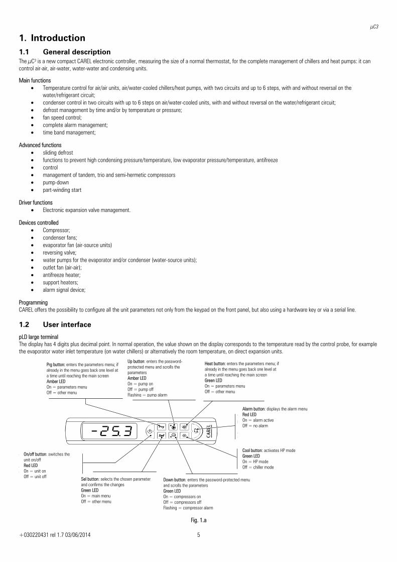
1.2 User interface
pLD large terminal The display has 4 digits plus decimal point. In normal operation, the value shown on the display corresponds to the temperature read by the control probe, for example the evaporator water inlet temperature (on water chillers) or alternatively the room temperature, on direct expansion units.
Fig. 1.a
Prg button: enters the parameters menu; if already in the menu goes back one level at a time until reaching the main screen Amber LED On = parameters menu Off = other menu
Up button: enters the password-protected menu and scrolls the parameters Amber LED On = pump on Off = pump off Flashing = pump alarm
Heat button: enters the parameters menu; if already in the menu goes back one level at a time until reaching the main screen Green LED On = parameters menu Off = other menu
Alarm button: displays the alarm menu Red LED On = alarm active Off = no alarm
Cool button: activates HP mode Green LED On = HP mode Off = chiller mode
Down button: enters the password-protected menu and scrolls the parameters Green LED On = compressors on Off = compressors off Flashing = compressor alarm
Sel button: selects the chosen parameter and confirms the changes Green LED On = main menu Off = other menu
On/off button: switches the unit on/off Red LED On = unit on Off = unit off
μC3
+030220431 rel 1.7 03/06/2014 6
1.3 Programming procedure 1) press up or down 2) press Sel 3) enter the password using up or down 4) press Sel to confirm
If the password is correct, the parameters menu automatically appears; if the password is wrong, the value 0 is displayed.
Repeat the operation by repeating the procedure or press Prg to exit.
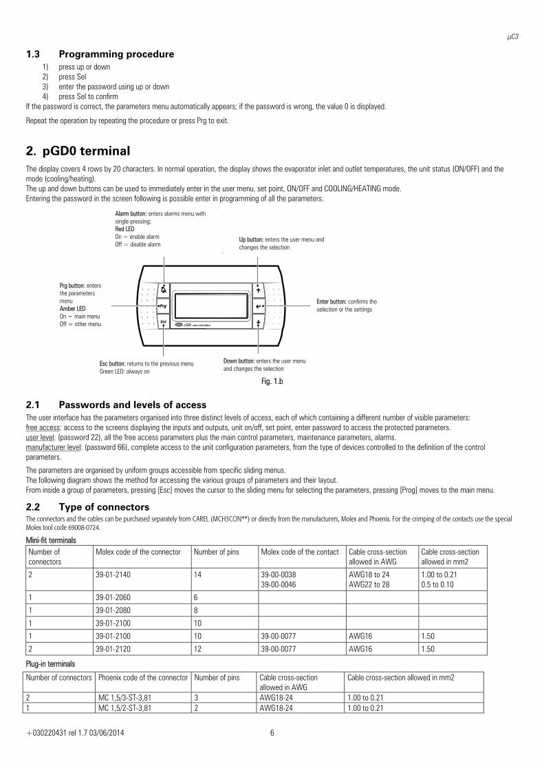
2. pGD0 terminal The display covers 4 rows by 20 characters. In normal operation, the display shows the evaporator inlet and outlet temperatures, the unit status (ON/OFF) and the mode (cooling/heating). The up and down buttons can be used to immediately enter in the user menu, set point, ON/OFF and COOLING/HEATING mode. Entering the password in the screen following is possible enter in programming of all the parameters.
Fig. 1.b
2.1 Passwords and levels of access The user interface has the parameters organised into three distinct levels of access, each of which containing a different number of visible parameters: free access: access to the screens displaying the inputs and outputs, unit on/off, set point, enter password to access the protected parameters. user level: (password 22), all the free access parameters plus the main control parameters, maintenance parameters, alarms. manufacturer level: (password 66), complete access to the unit configuration parameters, from the type of devices controlled to the definition of the control parameters.
The parameters are organised by uniform groups accessible from specific sliding menus. The following diagram shows the method for accessing the various groups of parameters and their layout. From inside a group of parameters, pressing [Esc] moves the cursor to the sliding menu for selecting the parameters, pressing [Prog] moves to the main menu.
2.2 Type of connectors The connectors and the cables can be purchased separately from CAREL (MCH3CON**) or directly from the manufacturers, Molex and Phoenix. For the crimping of the contacts use the special Molex tool code 69008-0724.
Mini-fit terminals Number of connectors
Molex code of the connector Number of pins Molex code of the contact Cable cross-section allowed in AWG
Cable cross-section allowed in mm2
2 39-01-2140 14 39-00-0038 39-00-0046
AWG18 to 24 AWG22 to 28
1.00 to 0.21 0.5 to 0.10
1 39-01-2060 6
1 39-01-2080 8
1 39-01-2100 10
1 39-01-2100 10 39-00-0077 AWG16 1.50
2 39-01-2120 12 39-00-0077 AWG16 1.50
Plug-in terminals
Number of connectors Phoenix code of the connector Number of pins Cable cross-section allowed in AWG
Cable cross-section allowed in mm2
2 MC 1,5/3-ST-3,81 3 AWG18-24 1.00 to 0.21 1 MC 1,5/2-ST-3,81 2 AWG18-24 1.00 to 0.21
Alarm button: enters alarms menu with single-pressing; Red LED On = enable alarm Off = disable alarm
Up button: enters the user menu and changes the selection
Enter button: confirms the selection or the settings
Down button: enters the user menu and changes the selection
Esc button: returns to the previous menu Green LED: always on
Prg button: enters the parameters menu Amber LED On = main menu Off = other menu
μC3
+030220431 rel 1.7 03/06/2014 7
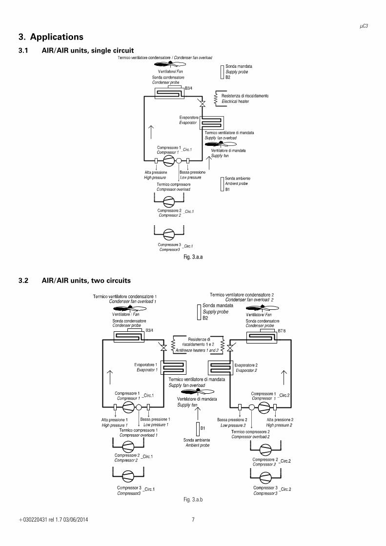
3. Applications 3.1 AIR/AIR units, single circuit
Fig. 3.a.a
3.2 AIR/AIR units, two circuits
Fig. 3.a.b
μC3
+030220431 rel 1.7 03/06/2014 8
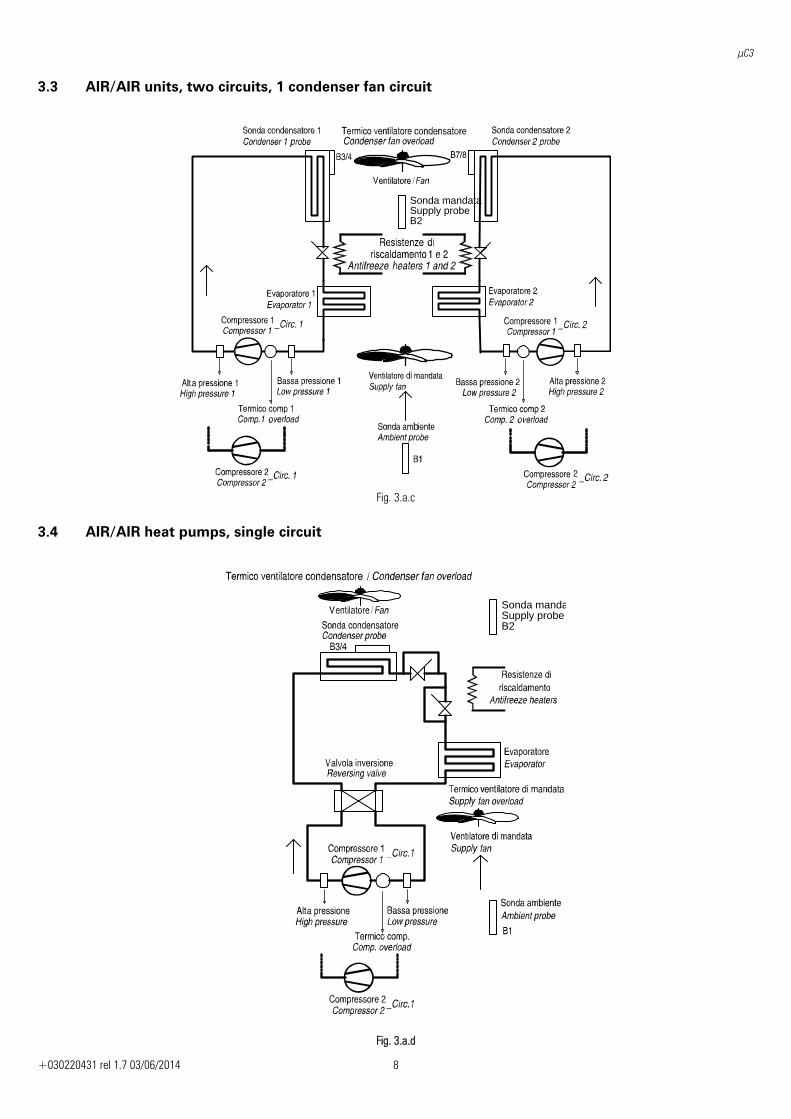
3.3 AIR/AIR units, two circuits, 1 condenser fan circuit
Sonda mandataSupply probeB2
b
Fig. 3.a.c
3.4 AIR/AIR heat pumps, single circuit
Sonda mandaSupply probeB2
Fig. 3.a.d
μC3
+030220431 rel 1.7 03/06/2014 9
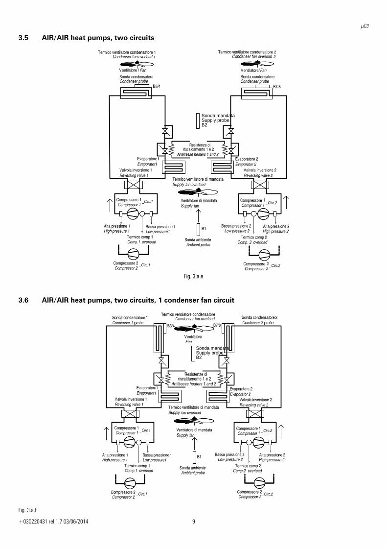
3.5 AIR/AIR heat pumps, two circuits
Sonda mandataSupply probeB2
Fig. 3.a.e
3.6 AIR/AIR heat pumps, two circuits, 1 condenser fan circuit
Sonda mandataSupply probeB2
p p
Fig. 3.a.f
μC3
+030220431 rel 1.7 03/06/2014 10
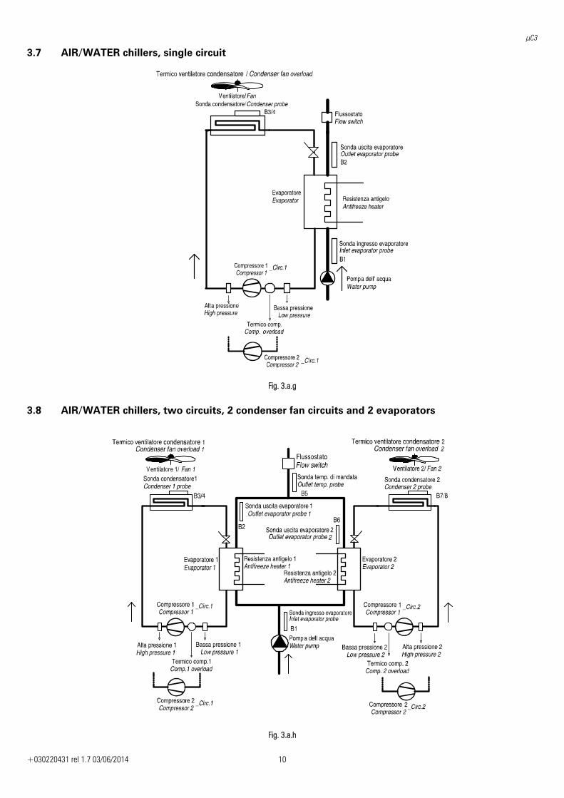
3.7 AIR/WATER chillers, single circuit
Fig. 3.a.g
3.8 AIR/WATER chillers, two circuits, 2 condenser fan circuits and 2 evaporators
Fig. 3.a.h
μC3
+030220431 rel 1.7 03/06/2014 11
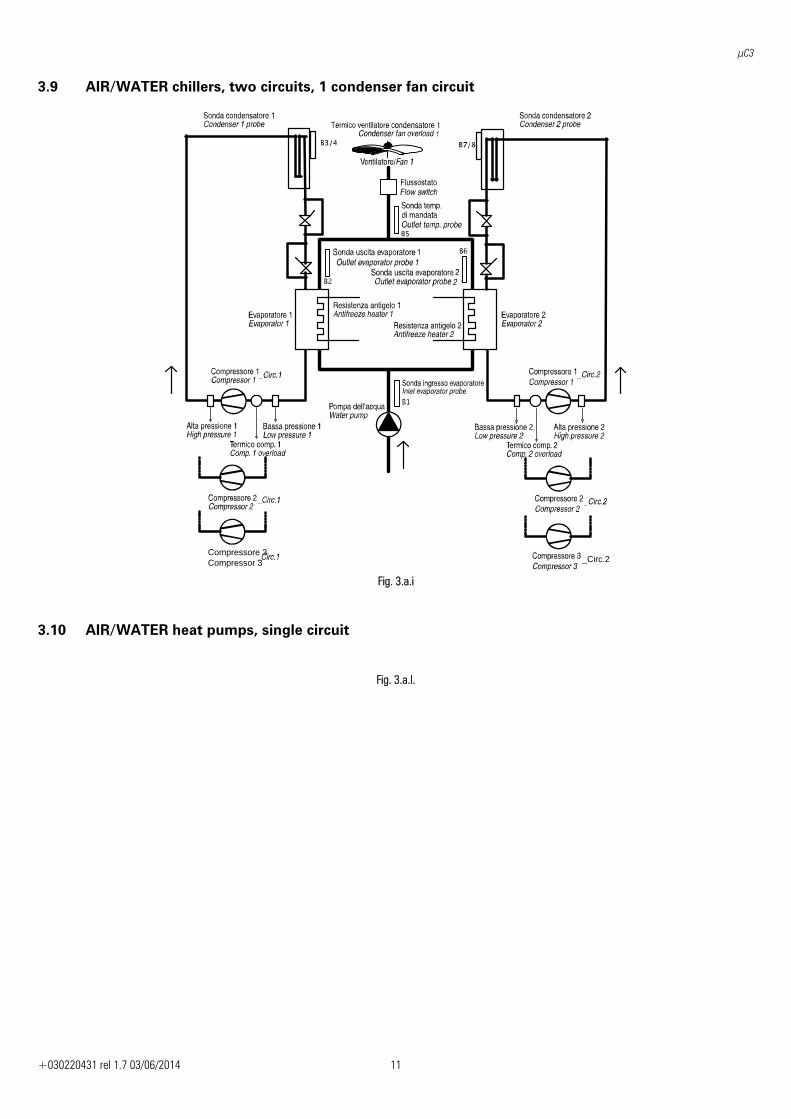
3.9 AIR/WATER chillers, two circuits, 1 condenser fan circuit
Compressore 3Compressor 3 _Circ.2
Fig. 3.a.i
3.10 AIR/WATER heat pumps, single circuit
Fig. 3.a.l.
μC3
+030220431 rel 1.7 03/06/2014 12
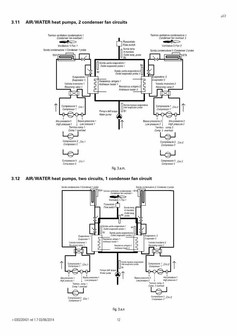
3.11 AIR/WATER heat pumps, 2 condenser fan circuits
Fig. 3.a.m.
3.12 AIR/WATER heat pumps, two circuits, 1 condenser fan circuit
Fig. 3.a.n
μC3
+030220431 rel 1.7 03/06/2014 13
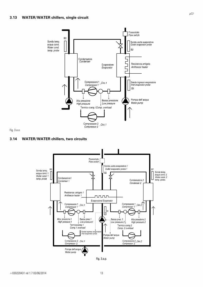
3.13 WATER/WATER chillers, single circuit
Fig. 3.a.o.
3.14 WATER/WATER chillers, two circuits
22
22
Fig. 3.a.p.
μC3
+030220431 rel 1.7 03/06/2014 14
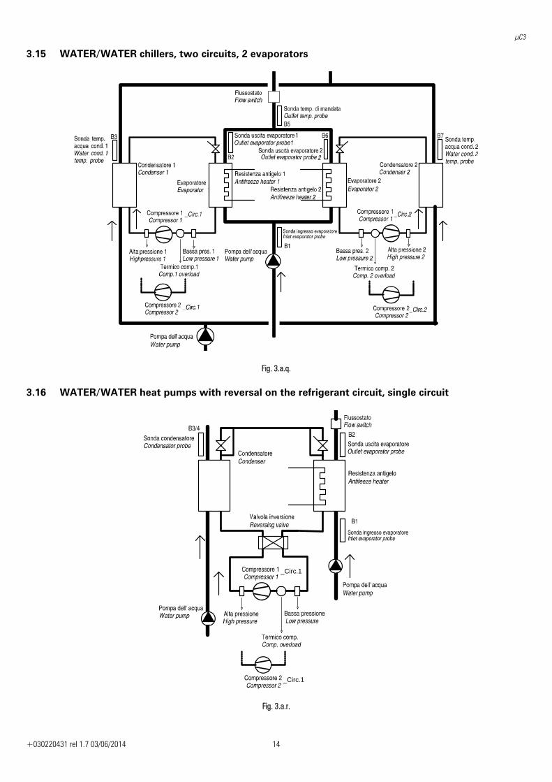
3.15 WATER/WATER chillers, two circuits, 2 evaporators
Fig. 3.a.q.
3.16 WATER/WATER heat pumps with reversal on the refrigerant circuit, single circuit
_Circ.1
_Circ.1
Fig. 3.a.r.
μC3
+030220431 rel 1.7 03/06/2014 15
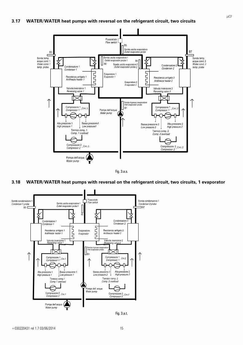
3.17 WATER/WATER heat pumps with reversal on the refrigerant circuit, two circuits
_Circ.1
_Circ.1
_Circ.2
_Circ.2
Fig. 3.a.s.
3.18 WATER/WATER heat pumps with reversal on the refrigerant circuit, two circuits, 1 evaporator
Fig. 3.a.t.
μC3
+030220431 rel 1.7 03/06/2014 16
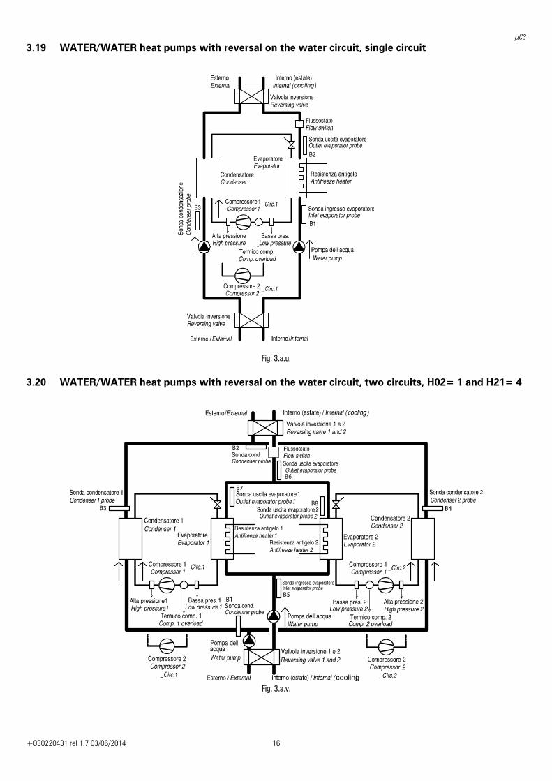
3.19 WATER/WATER heat pumps with reversal on the water circuit, single circuit
Fig. 3.a.u.
3.20 WATER/WATER heat pumps with reversal on the water circuit, two circuits, H02= 1 and H21= 4
cooling Fig. 3.a.v.
μC3
+030220431 rel 1.7 03/06/2014 17
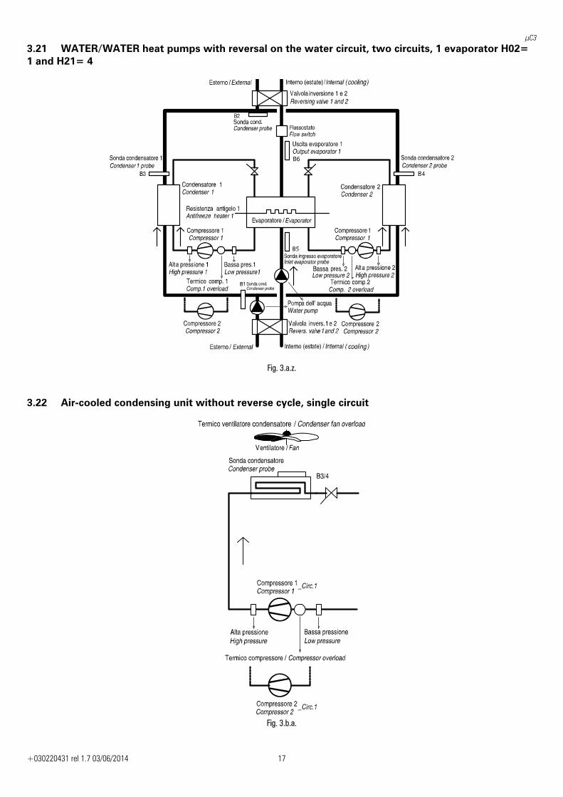
3.21 WATER/WATER heat pumps with reversal on the water circuit, two circuits, 1 evaporator H02= 1 and H21= 4
Fig. 3.a.z.
3.22 Air-cooled condensing unit without reverse cycle, single circuit
Fig. 3.b.a.
μC3
+030220431 rel 1.7 03/06/2014 18
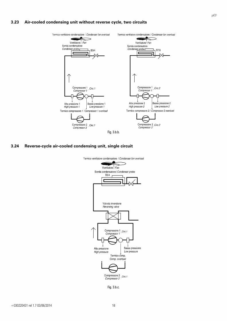
3.23 Air-cooled condensing unit without reverse cycle, two circuits
Fig. 3.b.b.
3.24 Reverse-cycle air-cooled condensing unit, single circuit
Fig. 3.b.c.

μC3
+030220431 rel 1.7 03/06/2014 19
3.25 Reverse-cycle air-cooled condensing unit, two circuits with condenser fan circuit
Fig. 3.b.d.
3.26 Water-cooled condensing unit without reverse cycle, single circuit
Fig. 3.b.e.
μC3
+030220431 rel 1.7 03/06/2014 20
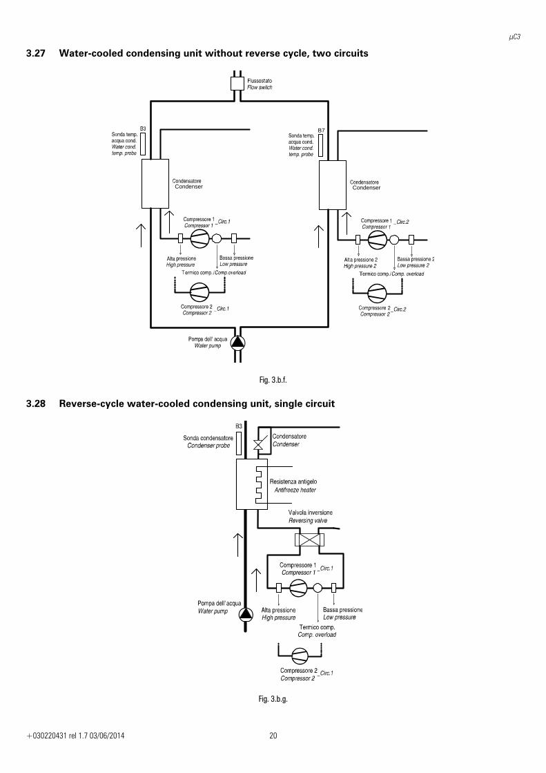
3.27 Water-cooled condensing unit without reverse cycle, two circuits
B7
Condenser Condenser
Fig. 3.b.f.
3.28 Reverse-cycle water-cooled condensing unit, single circuit
Fig. 3.b.g.
μC3
+030220431 rel 1.7 03/06/2014 21
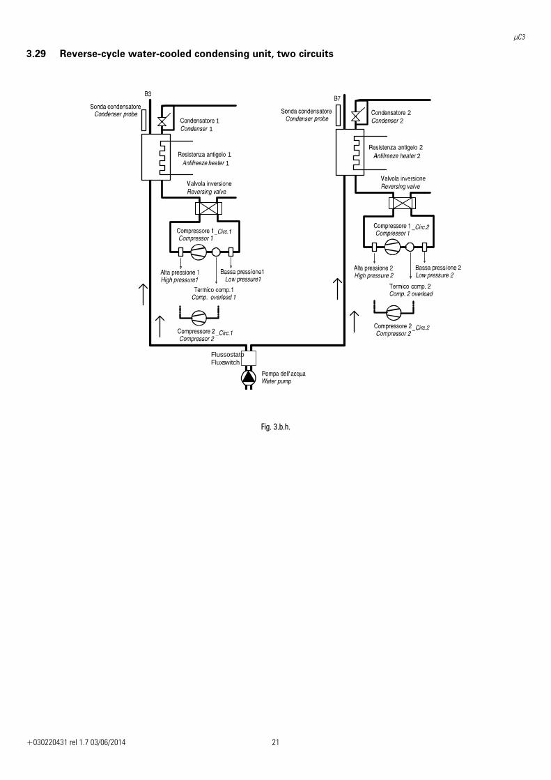
3.29 Reverse-cycle water-cooled condensing unit, two circuits
11
11
22
22
FlussostatoFluxswitch
Fig. 3.b.h.
μC3
+030220431 rel 1.7 03/06/2014 22
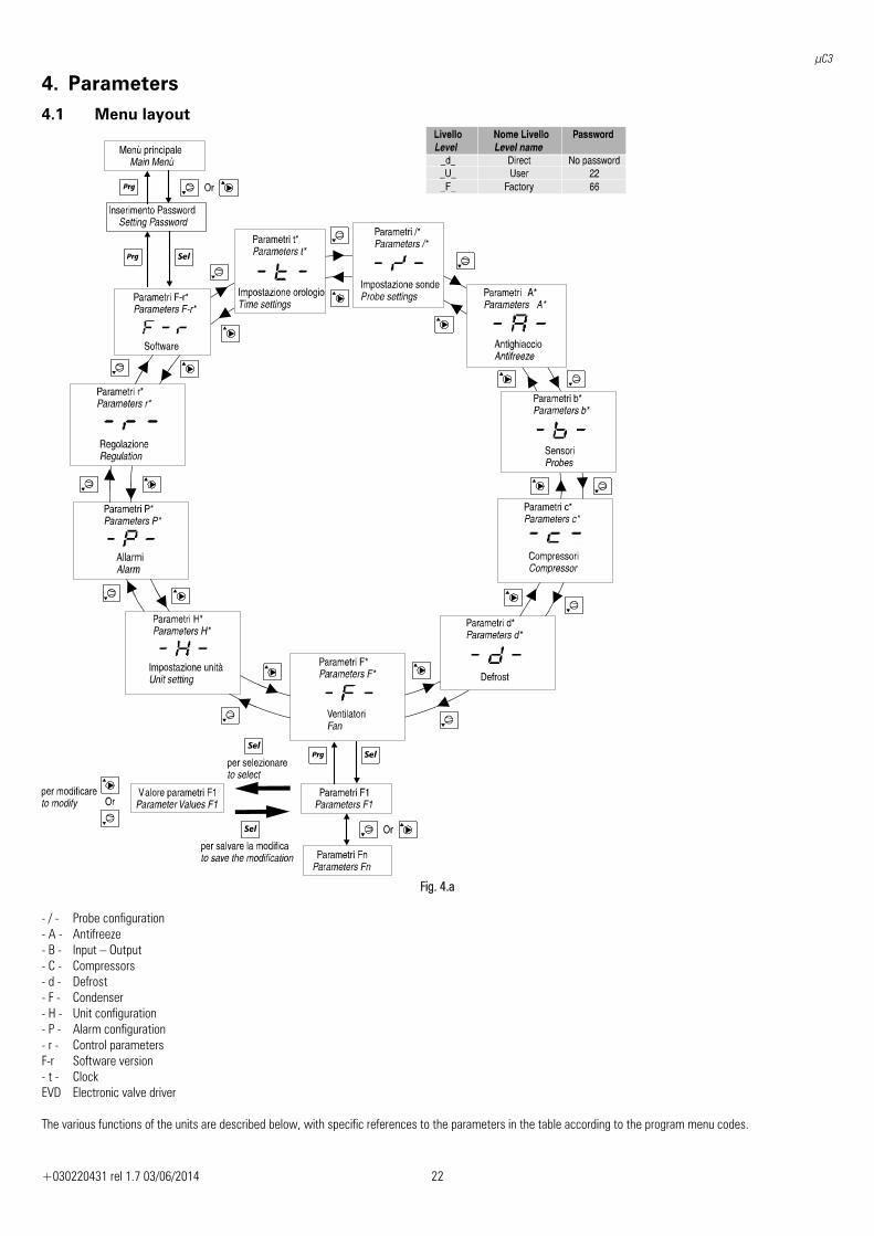
4. Parameters 4.1 Menu layout
Fig. 4.a
- / - Probe configuration - A - Antifreeze - B - Input – Output - C - Compressors - d - Defrost - F - Condenser - H - Unit configuration - P - Alarm configuration - r - Control parameters F-r Software version - t - Clock EVD Electronic valve driver The various functions of the units are described below, with specific references to the parameters in the table according to the program menu codes.
μC3
+030220431 rel 1.7 03/06/2014 23
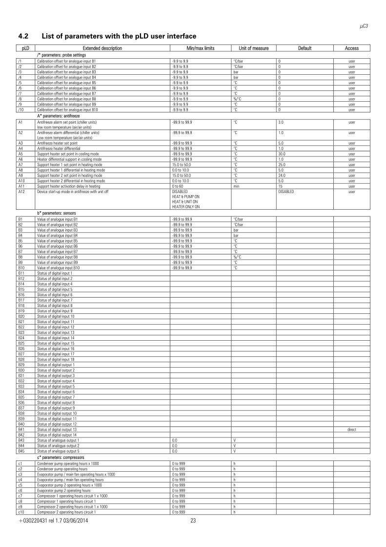
4.2 List of parameters with the pLD user interface
pLD Extended description Min/max limits Unit of measure Default Access /* parameters: probe settings /1 Calibration offset for analogue input B1 -9.9 to 9.9 °C/bar 0 user /2 Calibration offset for analogue input B2 -9.9 to 9.9 °C/bar 0 user /3 Calibration offset for analogue input B3 -9.9 to 9.9 bar 0 user /4 Calibration offset for analogue input B4 -9.9 to 9.9 bar 0 user /5 Calibration offset for analogue input B5 -9.9 to 9.9 °C 0 user /6 Calibration offset for analogue input B6 -9.9 to 9.9 °C 0 user /7 Calibration offset for analogue input B7 -9.9 to 9.9 °C 0 user /8 Calibration offset for analogue input B8 -9.9 to 9.9 %/°C 0 user /9 Calibration offset for analogue input B9 -9.9 to 9.9 °C 0 user /10 Calibration offset for analogue input B10 -9.9 to 9.9 °C 0 user A* parameters: antifreeze A1 Antifreeze alarm set point (chiller units)
low room temperature (air/air units) -99.9 to 99.9 °C 3.0 user
A2 Antifreeze alarm differential (chiller units) Low room temperature (air/air units)
-99.9 to 99.9 °C 1.0 user
A3 Antifreeze heater set point -99.9 to 99.9 °C 5.0 user A4 Antifreeze heater differential -99.9 to 99.9 °C 1.0 user A5 Support heater set point in cooling mode -99.9 to 99.9 °C 30.0 user A6 Heater differential support in cooling mode -99.9 to 99.9 °C 1.0 user A7 Support heater 1 set point in heating mode 15.0 to 50.0 °C 25.0 user A8 Support heater 1 differential in heating mode 0.0 to 10.0 °C 5.0 user A9 Support heater 2 set point in heating mode 15.0 to 50.0 °C 24.0 user A10 Support heater 2 differential in heating mode 0.0 to 10.0 °C 5.0 user A11 Support heater activation delay in heating 0 to 60 min 15 user A12 Device start-up mode in antifreeze with unit off
DISABLED HEAT & PUMP ON HEAT & UNIT ON HEATER ONLY ON
DISABLED user
b* parameters: sensors B1 Value of analogue input B1 -99.9 to 99.9 °C/bar B2 Value of analogue input B2 -99.9 to 99.9 °C/bar B3 Value of analogue input B3 -99.9 to 99.9 bar B4 Value of analogue input B4 -99.9 to 99.9 bar B5 Value of analogue input B5 -99.9 to 99.9 °C B6 Value of analogue input B6 -99.9 to 99.9 °C B7 Value of analogue input B7 -99.9 to 99.9 °C B8 Value of analogue input B8 -99.9 to 99.9 %/°C B9 Value of analogue input B9 -99.9 to 99.9 °C B10 Value of analogue input B10 -99.9 to 99.9 °C B11 Status of digital input 1 B12 Status of digital input 2 B14 Status of digital input 4 B15 Status of digital input 5 B16 Status of digital input 6 B17 Status of digital input 7 B18 Status of digital input 8 B19 Status of digital input 9 B20 Status of digital input 10 B21 Status of digital input 11 B22 Status of digital input 12 B23 Status of digital input 13 B24 Status of digital input 14 B25 Status of digital input 15 B26 Status of digital input 16 B27 Status of digital input 17 B28 Status of digital input 18 B29 Status of digital output 1 B30 Status of digital output 2 B31 Status of digital output 3 B32 Status of digital output 4 B33 Status of digital output 5 B34 Status of digital output 6 B35 Status of digital output 7 B36 Status of digital output 8 B37 Status of digital output 9 B38 Status of digital output 10 B39 Status of digital output 11 B40 Status of digital output 12 B41 Status of digital output 13 direct B42 Status of digital output 14 B43 Status of analogue output 1 0.0 V B44 Status of analogue output 2 0.0 V B45 Status of analogue output 5 0.0 V
c* parameters: compressors c1 Condenser pump operating hours x 1000 0 to 999 h c2 Condenser pump operating hours 0 to 999 h c3 Evaporator pump / main fan operating hours x 1000 0 to 999 h c4 Evaporator pump / main fan operating hours 0 to 999 h c5 Evaporator pump 2 operating hours x 1000 0 to 999 h c6 Evaporator pump 2 operating hours 0 to 999 h c7 Compressor 1 operating hours circuit 1 x 1000 0 to 999 h c8 Compressor 1 operating hours circuit 1 0 to 999 h c9 Compressor 2 operating hours circuit 1 x 1000 0 to 999 h c10 Compressor 2 operating hours circuit 1 0 to 999 h
μC3
+030220431 rel 1.7 03/06/2014 24
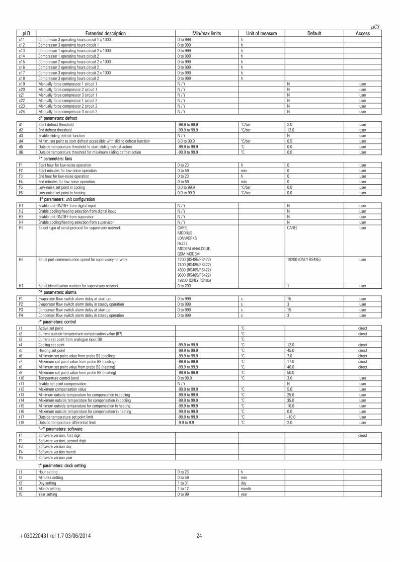
pLD Extended description Min/max limits Unit of measure Default Access c11 Compressor 3 operating hours circuit 1 x 1000 0 to 999 h c12 Compressor 3 operating hours circuit 1 0 to 999 h c13 Compressor 1 operating hours circuit 2 x 1000 0 to 999 h c14 Compressor 1 operating hours circuit 2 0 to 999 h c15 Compressor 2 operating hours circuit 2 x 1000 0 to 999 h c16 Compressor 2 operating hours circuit 2 0 to 999 h c17 Compressor 3 operating hours circuit 2 x 1000 0 to 999 h c18 Compressor 3 operating hours circuit 2 0 to 999 h c19 Manually force compressor 1 circuit 1 N / Y N user c20 Manually force compressor 2 circuit 1 N / Y N user c21 Manually force compressor 3 circuit 1 N / Y N user c22 Manually force compressor 1 circuit 2 N / Y N user c23 Manually force compressor 2 circuit 2 N / Y N user c24 Manually force compressor 3 circuit 2 N / Y N user d* parameters: defrost d1 Start defrost threshold -99.9 to 99.9 °C/bar 2.0 user d2 End defrost threshold -99.9 to 99.9 °C/bar 12.0 user d3 Enable sliding defrost function N / Y N user d4 Minim. set point to start defrost accessible with sliding defrost function 0.0 to 99.9 °C/bar 0.5 user d5 Outside temperature threshold to start sliding defrost action -99.9 to 99.9 °C 0.0 user d6 Outside temperature threshold for maximum sliding defrost action -99.9 to 99.9 °C 0.0 user F* parameters: fans F1 Start hour for low-noise operation 0 to 23 h 0 user F2 Start minutes for low-noise operation 0 to 59 min 0 user F3 End hour for low-noise operation 0 to 23 h 0 user F4 End minutes for low-noise operation 0 to 59 min 0 user F5 Low-noise set point in cooling 0.0 to 99.9 °C/bar 0.0 user F6 Low-noise set point in heating 0.0 to 99.9 °C/bar 0.0 user H* parameters: unit configuration H1 Enable unit ON/OFF from digital input N / Y N user H2 Enable cooling/heating selection from digital input N / Y N user H3 Enable unit ON/OFF from supervisor N / Y N user H4 Enable cooling/heating selection from supervisor N / Y N user H5 Select type of serial protocol for supervisory network CAREL
MODBUS LONWORKS Rs232 MODEM ANALOGUE. GSM MODEM
CAREL user
H6 Serial port communication speed for supervisory network 1200 (RS485/RS422) 2400 (RS485/RS422) 4800 (RS485/RS422) 9600 (RS485/RS422) 19200 (ONLY RS485)
19200 (ONLY RS485) user
H7 Serial identification number for supervisory network 0 to 200 1 user P* parameters: alarms P1 Evaporator flow switch alarm delay at start-up 0 to 999 s 15 user P2 Evaporator flow switch alarm delay in steady operation 0 to 999 s 3 user P3 Condenser flow switch alarm delay at start-up 0 to 999 s 15 user P4 Condenser flow switch alarm delay in steady operation 0 to 999 s 3 user r* parameters: control r1 Active set point °C direct r2 Current outside temperature compensation value (B7) °C direct r3 Current set point from analogue input B8 °C r4 Cooling set point -99.9 to 99.9 °C 12.0 direct r5 Heating set point -99.9 to 99.9 °C 45.0 direct r6 Minimum set point value from probe B8 (cooling) -99.9 to 99.9 °C 7.0 direct r7 Maximum set point value from probe B8 (cooling) -99.9 to 99.9 °C 17.0 direct r8 Minimum set point value from probe B8 (heating) -99.9 to 99.9 °C 40.0 direct r9 Maximum set point value from probe B8 (heating) -99.9 to 99.9 °C 50.0 r10 Temperature control band 0 to 99.9 °C 3.0 user r11 Enable set point compensation N / Y N user r12 Maximum compensation value -99.9 to 99.9 °C 5.0 user r13 Minimum outside temperature for compensation in cooling -99.9 to 99.9 °C 25.0 user r14 Maximum outside temperature for compensation in cooling -99.9 to 99.9 °C 35.0 user r15 Minimum outside temperature for compensation in heating -99.9 to 99.9 °C 10.0 user r16 Maximum outside temperature for compensation in heating -99.9 to 99.9 °C 0.0 user r17 Outside temperature set point limit -99.9 to 99.9 °C -10.0 user r18 Outside temperature differential limit -9.9 to 9.9 °C 2.0 user
F-r* parameters: software F1 Software version, first digit direct F1 Software version, second digit F3 Software version day F4 Software version month F5 Software version year
t* parameters: clock setting t1 Hour setting 0 to 23 h t2 Minutes setting 0 to 59 min t3 Day setting 1 to 31 day t4 Month setting 1 to 12 month t5 Year setting 0 to 99 year
μC3
+030220431 rel 1.7 03/06/2014 25
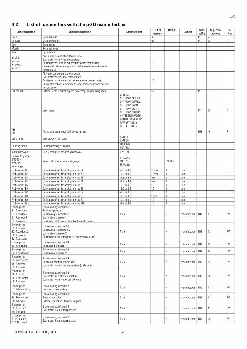
4.3 List of parameters with the pGD user interface Menu description Extended description Min/max limits Unit of
measure Default
Access Ana/Int/Dig
Supervisor address
R / R-W
Hour System hours h INT 77 RMinutes System minutes m INT 76 RDay System day Month System month Year System year
In. air t. In. evap.t. In. cond.t. In. diff.t.
Ambient air temperature (air/air units) Evaporator water inlet temperature Condenser water inlet temperature (water/water units) Differential between evaporator inlet temperature and outside temperature
°C
Air outlet temperature (air/air units) Evaporator water outlet temperature Condenser water outlet temperature (water/water units) Differential between evaporator outlet temperature and outside temperature
°C
Ext.control External temp. control request percentage (condensing units) % INT 51 R
Unit status
UNIT ONOFF FROM ALARM OFF FROM SUPERV. OFF FROM BANDS OFF FROM DIG.IN. OFF FROM BUTTON ANTIFREEZE PROBE P/LOAD PREVENT HP DEFROST CIRC.1 DEFROST CIRC.2
INT 50 R
CH HP Active operating mode (chiller/heat pump) DIG 46 R
On/Off unit Unit ON/OFF from panel UNIT OFFUNIT ON
Running mode Cooling/Heating from panel COOLINGHEATING
Insert password User / Manufacturer access password 0 to 9999 Current language: ENGLISH press [ ] for change
Select pGD user interface language ITALIANO ENGLISH ESPAÑOL
ENGLISH
Probe offset B1: Calibration offset for analogue input B1 -9.9 to 9.9 °C/bar 0 user Probe offset B2: Calibration offset for analogue input B2 -9.9 to 9.9 °C/bar 0 user Probe offset B3: Calibration offset for analogue input B3 -9.9 to 9.9 bar 0 user Probe offset B4: Calibration offset for analogue input B4 -9.9 to 9.9 bar 0 user Probe offset B5: Calibration offset for analogue input B5 -9.9 to 9.9 °C 0 user Probe offset B6: Calibration offset for analogue input B6 -9.9 to 9.9 °C 0 user Probe offset B7: Calibration offset for analogue input B7 -9.9 to 9.9 °C 0 user Probe offset B8: Calibration offset for analogue input B8 -9.9 to 9.9 %/°C 0 user Probe offset B9: Calibration offset for analogue input B9 -9.9 to 9.9 °C 0 user Probe offset B10: Calibration offset for analogue input B10 -9.9 to 9.9 °C 0 user Enable probe B1: Tank temp. B1: T.condens.1 B1: P.evapor.1 B1: T.in.cond
Enable analogue input B1 Boiler temperature Condensing temperature 1 Evaporation pressure 1 Condenser inlet temperature (water/water units)
N / Y N manufacturer DIG 11 RW
Enable probe B2: Not used B2: T.condens.2 B2: P.evapor.2 B2: T.out.cond
Enable analogue input B2 Condensing temperature 2 Evaporation pressure 2 Condenser outlet temperature (water/water units)
N / Y N manufacturer DIG 12 RW
Enable probe B3: P.condens.1
Enable analogue input B3 Condensing pressure 1 N / Y N manufacturer DIG 13 RW
Enable probe B4: P.condens.2
Enable analogue input B4 Condensing pressure 2 N / Y N manufacturer DIG 14 RW
Enable probe B5: Room temp. B5: T.in.evap B5: Not used
Enable analogue input B5 Room temperature (air/air units) Evaporator water inlet temperature (chiller units)
N / Y Y manufacturer DIG 15 RW
Enable probe B6: T.out.air B6: T.out.water B6: Not used
Enable analogue input B6 Evaporator air outlet temperature Evaporator water outlet temperature
N / Y Y manufacturer DIG 16 RW
Enable probe B7: External temp.
Enable analogue input B7 Outside air temperature N / Y N manufacturer DIG 17 RW
Enable probe B8: External set B8: Ext.contr.
Enable analogue input B8 External set point External control unit (condensing units)
N / Y N manufacturer DIG 18 RW
Enable probe B9: T.out.ev.1 B9: Not used
Enable analogue input B9 Evaporator 1 outlet temperature N / Y N manufacturer DIG 19 RW
Enable probe B10: T.out.ev.2 B10: Not used
Enable analogue input B10 Evaporator 2 outlet temperature N / Y N manufacturer DIG 20 RW
μC3
+030220431 rel 1.7 03/06/2014 26
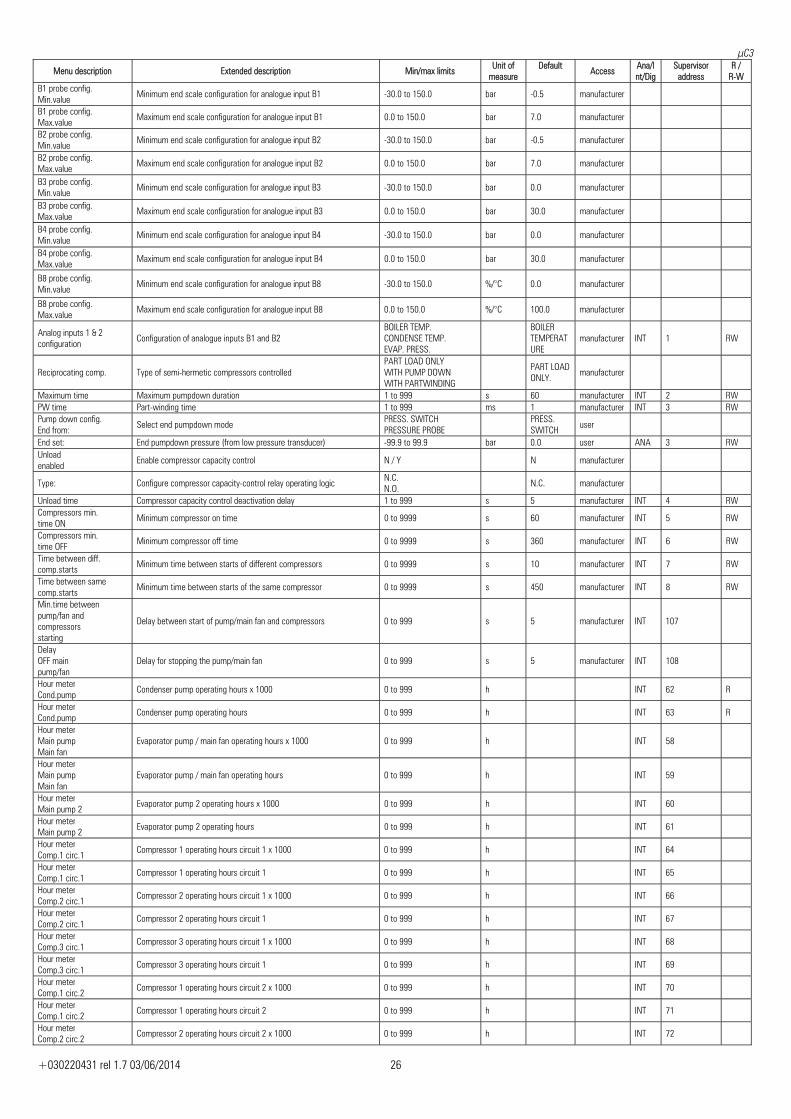
Menu description Extended description Min/max limits Unit of measure
Default Access Ana/I
nt/DigSupervisor
address R /
R-W B1 probe config. Min.value Minimum end scale configuration for analogue input B1 -30.0 to 150.0 bar -0.5 manufacturer
B1 probe config. Max.value Maximum end scale configuration for analogue input B1 0.0 to 150.0 bar 7.0 manufacturer
B2 probe config. Min.value Minimum end scale configuration for analogue input B2 -30.0 to 150.0 bar -0.5 manufacturer
B2 probe config. Max.value Maximum end scale configuration for analogue input B2 0.0 to 150.0 bar 7.0 manufacturer
B3 probe config. Min.value Minimum end scale configuration for analogue input B3 -30.0 to 150.0 bar 0.0 manufacturer
B3 probe config. Max.value Maximum end scale configuration for analogue input B3 0.0 to 150.0 bar 30.0 manufacturer
B4 probe config. Min.value Minimum end scale configuration for analogue input B4 -30.0 to 150.0 bar 0.0 manufacturer
B4 probe config. Max.value Maximum end scale configuration for analogue input B4 0.0 to 150.0 bar 30.0 manufacturer
B8 probe config. Min.value Minimum end scale configuration for analogue input B8 -30.0 to 150.0 %/°C 0.0 manufacturer
B8 probe config. Max.value Maximum end scale configuration for analogue input B8 0.0 to 150.0 %/°C 100.0 manufacturer
Analog inputs 1 & 2 configuration Configuration of analogue inputs B1 and B2
BOILER TEMP. CONDENSE TEMP. EVAP. PRESS.
BOILER TEMPERATURE
manufacturer INT 1 RW
Reciprocating comp. Type of semi-hermetic compressors controlled PART LOAD ONLYWITH PUMP DOWN WITH PARTWINDING
PART LOAD ONLY. manufacturer
Maximum time Maximum pumpdown duration 1 to 999 s 60 manufacturer INT 2 RWPW time Part-winding time 1 to 999 ms 1 manufacturer INT 3 RWPump down config. End from: Select end pumpdown mode PRESS. SWITCH
PRESSURE PROBE PRESS. SWITCH user
End set: End pumpdown pressure (from low pressure transducer) -99.9 to 99.9 bar 0.0 user ANA 3 RW Unload enabled Enable compressor capacity control N / Y N manufacturer
Type: Configure compressor capacity-control relay operating logic N.C.N.O. N.C. manufacturer
Unload time Compressor capacity control deactivation delay 1 to 999 s 5 manufacturer INT 4 RWCompressors min. time ON Minimum compressor on time 0 to 9999 s 60 manufacturer INT 5 RW
Compressors min. time OFF Minimum compressor off time 0 to 9999 s 360 manufacturer INT 6 RW
Time between diff. comp.starts Minimum time between starts of different compressors 0 to 9999 s 10 manufacturer INT 7 RW
Time between same comp.starts Minimum time between starts of the same compressor 0 to 9999 s 450 manufacturer INT 8 RW
Min.time between pump/fan and compressors starting
Delay between start of pump/main fan and compressors 0 to 999 s 5 manufacturer INT 107
Delay OFF main pump/fan
Delay for stopping the pump/main fan 0 to 999 s 5 manufacturer INT 108
Hour meter Cond.pump Condenser pump operating hours x 1000 0 to 999 h INT 62 R
Hour meter Cond.pump Condenser pump operating hours 0 to 999 h INT 63 R
Hour meter Main pump Main fan
Evaporator pump / main fan operating hours x 1000 0 to 999 h INT 58
Hour meter Main pump Main fan
Evaporator pump / main fan operating hours 0 to 999 h INT 59
Hour meter Main pump 2 Evaporator pump 2 operating hours x 1000 0 to 999 h INT 60
Hour meter Main pump 2 Evaporator pump 2 operating hours 0 to 999 h INT 61
Hour meter Comp.1 circ.1 Compressor 1 operating hours circuit 1 x 1000 0 to 999 h INT 64
Hour meter Comp.1 circ.1 Compressor 1 operating hours circuit 1 0 to 999 h INT 65
Hour meter Comp.2 circ.1 Compressor 2 operating hours circuit 1 x 1000 0 to 999 h INT 66
Hour meter Comp.2 circ.1 Compressor 2 operating hours circuit 1 0 to 999 h INT 67
Hour meter Comp.3 circ.1 Compressor 3 operating hours circuit 1 x 1000 0 to 999 h INT 68
Hour meter Comp.3 circ.1 Compressor 3 operating hours circuit 1 0 to 999 h INT 69
Hour meter Comp.1 circ.2 Compressor 1 operating hours circuit 2 x 1000 0 to 999 h INT 70
Hour meter Comp.1 circ.2 Compressor 1 operating hours circuit 2 0 to 999 h INT 71
Hour meter Comp.2 circ.2 Compressor 2 operating hours circuit 2 x 1000 0 to 999 h INT 72
μC3
+030220431 rel 1.7 03/06/2014 27
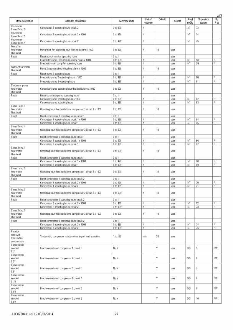
Menu description Extended description Min/max limits Unit of measure
Default Access Ana/I
nt/DigSupervisor
address R /
R-W Hour meter Comp.2 circ.2 Compressor 2 operating hours circuit 2 0 to 999 h INT 73
Hour meter Comp.3 circ.2 Compressor 3 operating hours circuit 2 x 1000 0 to 999 h INT 74
Hour meter Comp.3 circ.2 Compressor 3 operating hours circuit 2 0 to 999 h INT 75
Pump/Fan hour meter Threshold
Pump/main fan operating hour threshold alarm x 1000 0 to 999 h 10 user
Reset Reset pump/main fan operating hours 0 to 1 user Evaporator pump / main fan operating hours x 1000 0 to 999 h user INT 58 R Evaporator main pump fan operating hours 0 to 999 h user INT 59 RPump 2 hour meter Threshold Pump 2 operating hour threshold alarm x 1000 0 to 999 h 10 user
Reset Reset pump 2 operating hours 0 to 1 user Evaporator pump 2 operating hours x 1000 0 to 999 h user INT 60 R Evaporator pump 2 operating hours 0 to 999 h user INT 61 R Condenser pump hour meter Threshold
Condenser pump operating hour threshold alarm x 1000 0 to 999 h 10 user
Reset Reset condenser pump operating hours 0 to 1 user Condenser pump operating hours x 1000 0 to 999 h user INT 62 R Condenser pump operating hours 0 to 999 h user INT 63 RComp.1 circ.1 hour meter Threshold
Operating hour threshold alarm, compressor 1 circuit 1 x 1000 0 to 999 h 10 user
Reset Reset compressor 1 operating hours circuit 1 0 to 1 user Compressor 1 operating hours circuit 1 x 1000 0 to 999 h user INT 64 R Compressor 1 operating hours circuit 1 0 to 999 h user INT 65 RComp.2 circ.1 hour meter Threshold
Operating hour threshold alarm, compressor 2 circuit 1 x 1000 0 to 999 h 10 user
Reset Reset compressor 2 operating hours circuit 1 0 to 1 user Compressor 2 operating hours circuit 1 x 1000 0 to 999 h user INT 66 R Compressor 2 operating hours circuit 1 0 to 999 h user INT 67 RComp.3 circ.1 hour meter Threshold
Operating hour threshold alarm, compressor 3 circuit 1 x 1000 0 to 999 h 10 user
Reset Reset compressor 3 operating hours circuit 1 0 to 1 user Compressor 3 operating hours circuit 1 x 1000 0 to 999 h user INT 68 R Compressor 3 operating hours circuit 1 0 to 999 h user INT 69 RComp.1 circ.2 hour meter Threshold
Operating hour threshold alarm, compressor 1 circuit 2 x 1000 0 to 999 h 10 user
Reset Reset compressor 1 operating hours circuit 2 0 to 1 user Compressor 1 operating hours circuit 2 x 1000 0 to 999 h user INT 70 R Compressor 1 operating hours circuit 2 0 to 999 h user INT 71 RComp.2 circ.2 hour meter Threshold
Operating hour threshold alarm, compressor 2 circuit 2 x 1000 0 to 999 h 10 user
Reset Reset compressor 2 operating hours circuit 2 0 to 1 user Compressor 2 operating hours circuit 2 x 1000 0 to 999 h user INT 72 R Compressor 2 operating hours circuit 2 0 to 999 h user INT 73 RComp.3 circ.2 hour meter Threshold
Operating hour threshold alarm, compressor 3 circuit 2 x 1000 0 to 999 h 10 user
Reset Reset compressor 3 operating hours circuit 2 0 to 1 user Compressor 3 operating hours circuit 2 x 1000 0 to 999 h user INT 74 R Compressor 3 operating hours circuit 2 0 to 999 h user INT 75 RRotation time with tandem/trio compressors:
Tandem/trio compressor rotation delay in part load operation 1 to 180 min 20 user
Compressors enabled C1/1
Enable operation of compressor 1 circuit 1 N / Y Y user DIG 5 RW
Compressors enabled C2/1
Enable operation of compressor 2 circuit 1 N / Y Y user DIG 6 RW
Compressors enabled C3/1
Enable operation of compressor 3 circuit 1 N / Y Y user DIG 7 RW
Compressors enabled C1/2
Enable operation of compressor 1 circuit 2 N / Y Y user DIG 8 RW
Compressors enabled C2/2
Enable operation of compressor 2 circuit 2 N / Y Y user DIG 9 RW
Compressors enabled C3/2
Enable operation of compressor 3 circuit 2 N / Y Y user DIG 10 RW
μC3
+030220431 rel 1.7 03/06/2014 28
Menu description Extended description Min/max limits Unit of measure
Default Access Ana/I
nt/DigSupervisor
address R /
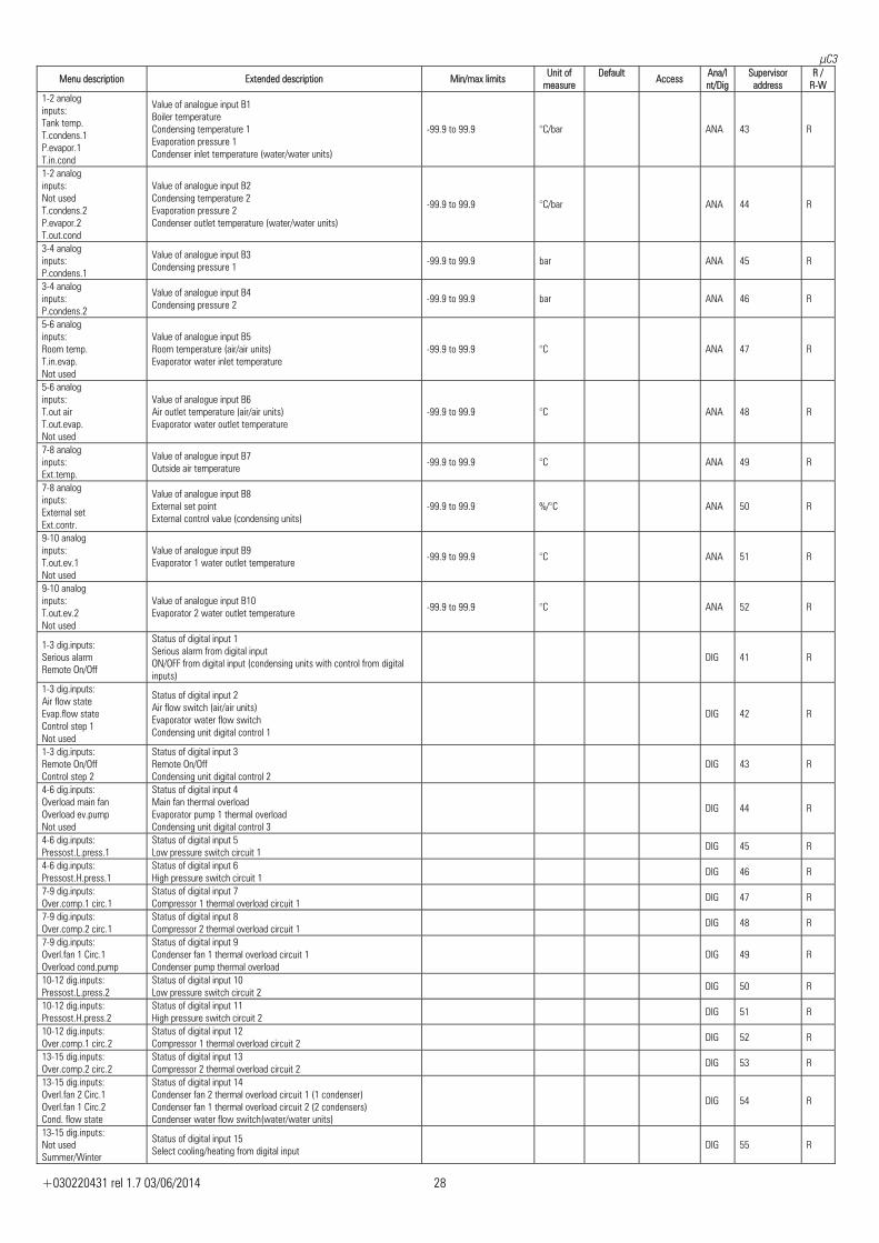
R-W 1-2 analog inputs: Tank temp. T.condens.1 P.evapor.1 T.in.cond
Value of analogue input B1 Boiler temperature Condensing temperature 1 Evaporation pressure 1 Condenser inlet temperature (water/water units)
-99.9 to 99.9 °C/bar ANA 43 R
1-2 analog inputs: Not used T.condens.2 P.evapor.2 T.out.cond
Value of analogue input B2 Condensing temperature 2 Evaporation pressure 2 Condenser outlet temperature (water/water units)
-99.9 to 99.9 °C/bar ANA 44 R
3-4 analog inputs: P.condens.1
Value of analogue input B3 Condensing pressure 1 -99.9 to 99.9 bar ANA 45 R
3-4 analog inputs: P.condens.2
Value of analogue input B4 Condensing pressure 2 -99.9 to 99.9 bar ANA 46 R
5-6 analog inputs: Room temp. T.in.evap. Not used
Value of analogue input B5 Room temperature (air/air units) Evaporator water inlet temperature
-99.9 to 99.9 °C ANA 47 R
5-6 analog inputs: T.out air T.out.evap. Not used
Value of analogue input B6 Air outlet temperature (air/air units) Evaporator water outlet temperature
-99.9 to 99.9 °C ANA 48 R
7-8 analog inputs: Ext.temp.
Value of analogue input B7 Outside air temperature -99.9 to 99.9 °C ANA 49 R
7-8 analog inputs: External set Ext.contr.
Value of analogue input B8 External set point External control value (condensing units)
-99.9 to 99.9 %/°C ANA 50 R
9-10 analog inputs: T.out.ev.1 Not used
Value of analogue input B9 Evaporator 1 water outlet temperature -99.9 to 99.9 °C ANA 51 R
9-10 analog inputs: T.out.ev.2 Not used
Value of analogue input B10 Evaporator 2 water outlet temperature -99.9 to 99.9 °C ANA 52 R
1-3 dig.inputs: Serious alarm Remote On/Off
Status of digital input 1 Serious alarm from digital input ON/OFF from digital input (condensing units with control from digital inputs)
DIG 41 R
1-3 dig.inputs: Air flow state Evap.flow state Control step 1 Not used
Status of digital input 2 Air flow switch (air/air units) Evaporator water flow switch Condensing unit digital control 1
DIG 42 R
1-3 dig.inputs: Remote On/Off Control step 2
Status of digital input 3 Remote On/Off Condensing unit digital control 2
DIG 43 R
4-6 dig.inputs: Overload main fan Overload ev.pump Not used
Status of digital input 4 Main fan thermal overload Evaporator pump 1 thermal overload Condensing unit digital control 3
DIG 44 R
4-6 dig.inputs: Pressost.L.press.1
Status of digital input 5 Low pressure switch circuit 1 DIG 45 R
4-6 dig.inputs: Pressost.H.press.1
Status of digital input 6 High pressure switch circuit 1 DIG 46 R
7-9 dig.inputs: Over.comp.1 circ.1
Status of digital input 7 Compressor 1 thermal overload circuit 1 DIG 47 R
7-9 dig.inputs: Over.comp.2 circ.1
Status of digital input 8 Compressor 2 thermal overload circuit 1 DIG 48 R
7-9 dig.inputs: Overl.fan 1 Circ.1 Overload cond.pump
Status of digital input 9 Condenser fan 1 thermal overload circuit 1 Condenser pump thermal overload
DIG 49 R
10-12 dig.inputs: Pressost.L.press.2
Status of digital input 10 Low pressure switch circuit 2 DIG 50 R
10-12 dig.inputs: Pressost.H.press.2
Status of digital input 11 High pressure switch circuit 2 DIG 51 R
10-12 dig.inputs: Over.comp.1 circ.2
Status of digital input 12 Compressor 1 thermal overload circuit 2 DIG 52 R
13-15 dig.inputs: Over.comp.2 circ.2
Status of digital input 13 Compressor 2 thermal overload circuit 2 DIG 53 R
13-15 dig.inputs: Overl.fan 2 Circ.1 Overl.fan 1 Circ.2 Cond. flow state
Status of digital input 14 Condenser fan 2 thermal overload circuit 1 (1 condenser) Condenser fan 1 thermal overload circuit 2 (2 condensers) Condenser water flow switch(water/water units)
DIG 54 R
13-15 dig.inputs: Not used Summer/Winter
Status of digital input 15 Select cooling/heating from digital input DIG 55 R
μC3
+030220431 rel 1.7 03/06/2014 29
Menu description Extended description Min/max limits Unit of measure
Default Access Ana/I
nt/DigSupervisor
address R /
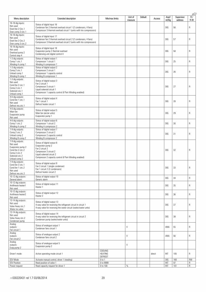
R-W 16-18 dig.inputs: Not used Overl.fan 2 Circ.1 Over.comp.3 circ.1
Status of digital input 16 Condenser fan 2 thermal overload circuit 1 (2 condensers, 4 fans) Compressor 3 thermal overload circuit 1 (units with trio compressors)
DIG 56 R
16-18 dig.inputs: Not used Overl.fan 2 Circ.2 Over.comp.3 circ.2
Status of digital input 17 Condenser fan 2 thermal overload circuit 2 (2 condensers, 4 fans) Compressor 3 thermal overload circuit 2 (units with trio compressors)
DIG 57 R
16-18 dig.inputs: Not used Overload pump 2 Control step 4
Status of digital input 18 Evaporator pump 2 thermal overload Condensing unit digital control 4
DIG 58 R
1-3 dig.outputs: Comp.1 circ.1 Winding A comp.1
Status of digital output 1 Compressor 1 circuit 1 Winding A compressor 1
DIG 25 R
1-3 dig.outputs: Comp.2 circ.1 Unload comp.1 Winding B comp.1
Status of digital output 2 Compressor 2 circuit 1 Compressor 1 capacity control Winding B compressor 1
DIG 26 R
1-3 dig.outputs: Not used Cond.fan 2 circ.1 Comp.3 circ.1 Solenoid circ.1 Unload comp.1
Status of digital output 3 Fan 2 circuit 1 Compressor 3 circuit 1 Liquid solenoid circuit 1 Compressor 1 capacity control (if Part-Winding enabled)
DIG 27 R
4-6 dig.outputs: Cond.fan 1 circ.1 Not used Defrost res.circ.1
Status of digital output 4 Fan 1 circuit 1 Defrost heater circuit 1
DIG 28 R
4-6 dig.outputs: Main fan Evaporator pump Not used
Status of digital output 5 Main fan (air/air units) Evaporator pump 1
DIG 29 R
4-6 dig.outputs: Comp.1 circ.2 Winding A comp.2
Status of digital output 6 Compressor 1 circuit 2 Winding A compressor 2
DIG 30 R
7-9 dig.outputs: Comp.2 circ.2 Unload comp.2 Winding B comp.2
Status of digital output 7 Compressor 2 circuit 2 Compressor 2 capacity control Winding B compressor 2
DIG 31 R
7-9 dig.outputs: Not used Evaporator pump 2 Cond.fan 2 circ.2 Comp.3 circ.2 Solenoid circ.2 Unload comp.2
Status of digital output 8 Evaporator pump 2 Fan 2 circuit 2 Compressor 3 circuit 2 Liquid solenoid circuit 2 Compressor 2 capacity control (if Part-Winding enabled)
DIG 32 R
7-9 dig.outputs: Cond.fan 2 circ.1 Cond.fan 1 circ.2 Not used Defrost res.circ.2
Status of digital output 9 Fan 2 circuit 1 (single condenser) Fan 1 circuit 2 (2 condensers) Defrost heater circuit 2
DIG 33 R
10-12 dig.outputs: General alarm
Status of digital output 10 Generic alarm DIG 34 R
10-12 dig.outputs: Antifreeze heater1 Not used
Status of digital output 11 Heater 1 DIG 35 R
10-12 dig.outputs: Antifreeze heater2 Not used
Status of digital output 12 Heater 2 DIG 36 R
13-14 dig.outputs: Not used Valve 4way circ.1 Water inv.valve
Status of digital output 13 4-way valve for reversing the refrigerant circuit in circuit 1 4-way valve for reversing the water circuit (water/water units)
DIG 37 R
13-14 dig.outputs: Not used Valve 4way circ.2 Condenser pump
Status of digital output 14 4-way valve for reversing the refrigerant circuit in circuit 2 Condenser pump (water/water units)
DIG 38 R
Analog outputs: Fan circuit 1
Status of analogue output 1 Condenser fans circuit 1 V ANA 55 R
Analog outputs: Fan circuit 2
Status of analogue output 2 Condenser fans circuit 2 V ANA 56 R
Analog outputs: Evap.pump 2
Status of analogue output 5 Evaporator pump 2 V
Driver1 mode: Active operating mode circuit 1 COOLINGHEATING DEFROST
direct INT 105 R
EEV Mode Activate manual control, driver 1 (reading) 0 to 1 DIG 160 RWEEV Position Read position of valve 1 0 to 9999 INT 97 RPower request Read capacity request for driver 1 0 to 100 % INT 101 R
μC3
+030220431 rel 1.7 03/06/2014 30
Menu description Extended description Min/max limits Unit of measure
Default Access Ana/I
nt/DigSupervisor
address R /
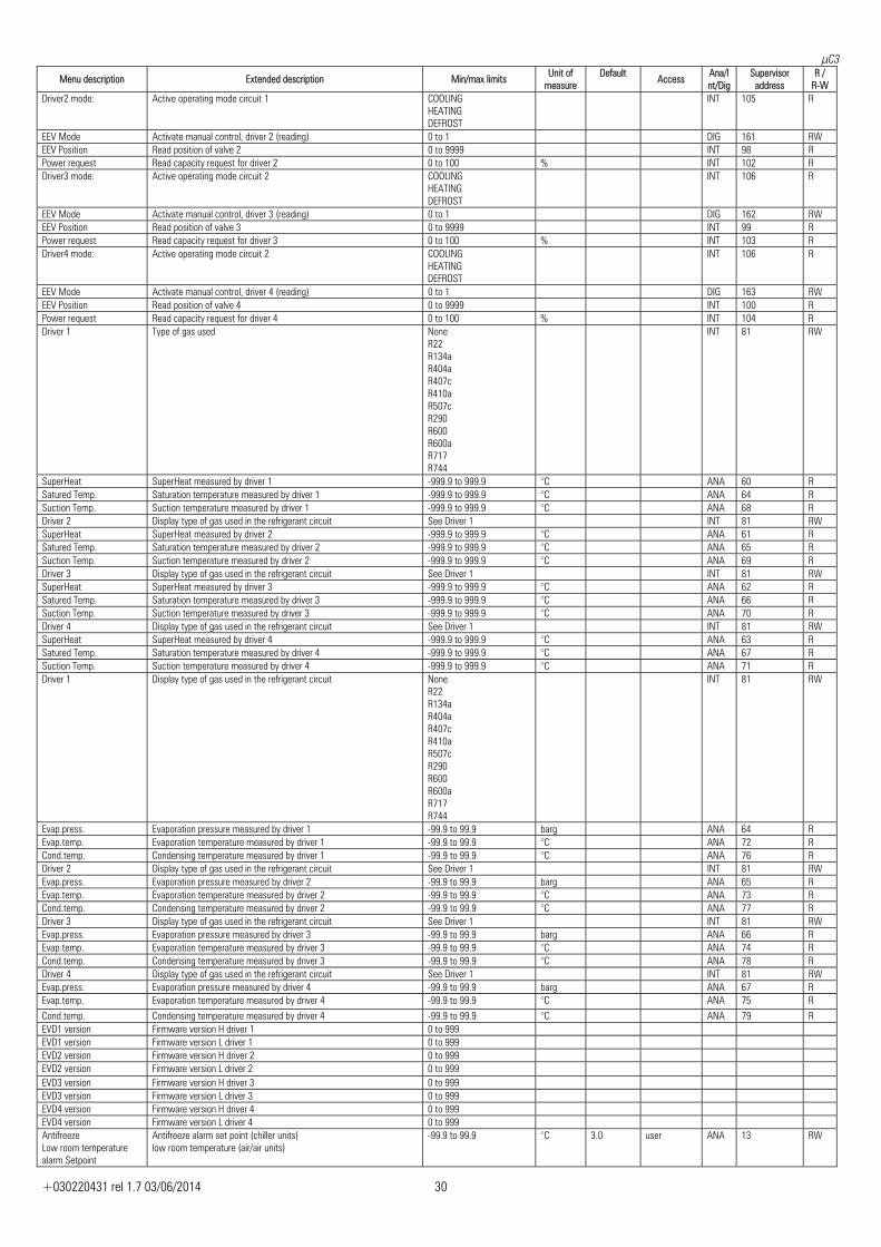
R-W Driver2 mode: Active operating mode circuit 1 COOLING
HEATING DEFROST
INT 105 R
EEV Mode Activate manual control, driver 2 (reading) 0 to 1 DIG 161 RWEEV Position Read position of valve 2 0 to 9999 INT 98 RPower request Read capacity request for driver 2 0 to 100 % INT 102 RDriver3 mode: Active operating mode circuit 2 COOLING
HEATING DEFROST
INT 106 R
EEV Mode Activate manual control, driver 3 (reading) 0 to 1 DIG 162 RWEEV Position Read position of valve 3 0 to 9999 INT 99 RPower request Read capacity request for driver 3 0 to 100 % INT 103 RDriver4 mode: Active operating mode circuit 2 COOLING
HEATING DEFROST
INT 106 R
EEV Mode Activate manual control, driver 4 (reading) 0 to 1 DIG 163 RWEEV Position Read position of valve 4 0 to 9999 INT 100 RPower request Read capacity request for driver 4 0 to 100 % INT 104 RDriver 1 Type of gas used None
R22 R134a R404a R407c R410a R507c R290 R600 R600a R717 R744
INT 81 RW
SuperHeat SuperHeat measured by driver 1 -999.9 to 999.9 °C ANA 60 RSatured Temp. Saturation temperature measured by driver 1 -999.9 to 999.9 °C ANA 64 RSuction Temp. Suction temperature measured by driver 1 -999.9 to 999.9 °C ANA 68 RDriver 2 Display type of gas used in the refrigerant circuit See Driver 1 INT 81 RWSuperHeat SuperHeat measured by driver 2 -999.9 to 999.9 °C ANA 61 RSatured Temp. Saturation temperature measured by driver 2 -999.9 to 999.9 °C ANA 65 RSuction Temp. Suction temperature measured by driver 2 -999.9 to 999.9 °C ANA 69 RDriver 3 Display type of gas used in the refrigerant circuit See Driver 1 INT 81 RWSuperHeat SuperHeat measured by driver 3 -999.9 to 999.9 °C ANA 62 RSatured Temp. Saturation temperature measured by driver 3 -999.9 to 999.9 °C ANA 66 RSuction Temp. Suction temperature measured by driver 3 -999.9 to 999.9 °C ANA 70 RDriver 4 Display type of gas used in the refrigerant circuit See Driver 1 INT 81 RWSuperHeat SuperHeat measured by driver 4 -999.9 to 999.9 °C ANA 63 RSatured Temp. Saturation temperature measured by driver 4 -999.9 to 999.9 °C ANA 67 RSuction Temp. Suction temperature measured by driver 4 -999.9 to 999.9 °C ANA 71 RDriver 1 Display type of gas used in the refrigerant circuit None
R22 R134a R404a R407c R410a R507c R290 R600 R600a R717 R744
INT 81 RW
Evap.press. Evaporation pressure measured by driver 1 -99.9 to 99.9 barg ANA 64 REvap.temp. Evaporation temperature measured by driver 1 -99.9 to 99.9 °C ANA 72 RCond.temp. Condensing temperature measured by driver 1 -99.9 to 99.9 °C ANA 76 RDriver 2 Display type of gas used in the refrigerant circuit See Driver 1 INT 81 RWEvap.press. Evaporation pressure measured by driver 2 -99.9 to 99.9 barg ANA 65 REvap.temp. Evaporation temperature measured by driver 2 -99.9 to 99.9 °C ANA 73 RCond.temp. Condensing temperature measured by driver 2 -99.9 to 99.9 °C ANA 77 RDriver 3 Display type of gas used in the refrigerant circuit See Driver 1 INT 81 RWEvap.press. Evaporation pressure measured by driver 3 -99.9 to 99.9 barg ANA 66 REvap.temp. Evaporation temperature measured by driver 3 -99.9 to 99.9 °C ANA 74 RCond.temp. Condensing temperature measured by driver 3 -99.9 to 99.9 °C ANA 78 RDriver 4 Display type of gas used in the refrigerant circuit See Driver 1 INT 81 RWEvap.press. Evaporation pressure measured by driver 4 -99.9 to 99.9 barg ANA 67 REvap.temp. Evaporation temperature measured by driver 4 -99.9 to 99.9 °C ANA 75 RCond.temp. Condensing temperature measured by driver 4 -99.9 to 99.9 °C ANA 79 REVD1 version Firmware version H driver 1 0 to 999 EVD1 version Firmware version L driver 1 0 to 999 EVD2 version Firmware version H driver 2 0 to 999 EVD2 version Firmware version L driver 2 0 to 999 EVD3 version Firmware version H driver 3 0 to 999 EVD3 version Firmware version L driver 3 0 to 999 EVD4 version Firmware version H driver 4 0 to 999 EVD4 version Firmware version L driver 4 0 to 999 Antifreeze Low room temperature alarm Setpoint
Antifreeze alarm set point (chiller units) low room temperature (air/air units)
-99.9 to 99.9 °C 3.0 user ANA 13 RW

μC3
+030220431 rel 1.7 03/06/2014 31
Menu description Extended description Min/max limits Unit of measure
Default Access Ana/I
nt/DigSupervisor
address R /
R-W Antifreeze Low room temperature alarm Diff.
Antifreeze alarm differential (chiller units) Low room temperature (air/air units)
-99.9 to 99.9 °C 1.0 user ANA 14 RW
Antifreeze alrm Low room temperature setpoint limits Low
Minimum set point limit antifreeze/low room temperature -99.9 to 99.9 °C 0.0 manufacturer 5
Antifreeze alrm Low room temperature setpoint limits High
Maximum set point limit antifreeze/low room temperature -99.9 to 99.9 °C 12.0 manufacturer
Antifreeze alarm Reset
Type of antifreeze alarm reset MANUALAUTOMATIC
MANUAL user
Antifreeze alarm Delay
Antifreeze alarm delay when starting (manual reset) 0 to 540 min 0 user INT 9 RW
Antifreeze heaters Setpont
Antifreeze heater set point -99.9 to 99.9 5.0 user ANA 15 RW
Antifreeze heaters Diff.
Antifreeze heater differential -99.9 to 99.9 1.0 user ANA 16 RW
Auxiliary heater in cooling mode Setpoint
Support heater set point in cooling mode -99.9 to 99.9 30.0 user ANA 17 RW
Auxiliary heater in cooling mode Diff.
Heater differential support in cooling mode -99.9 to 99.9 1.0 user ANA 18 RW
Auxiliary heater in heating mode Setpoint
Support heater 1 set point in heating mode 15.0 to 50.0 25.0 user ANA 19 RW
Auxiliary heater in heating mode Diff.
Support heater 1 differential in heating mode 0.0 to 10.0 5.0 user ANA 20 RW
Auxiliary heater in heating mode (2) Setpoint
Support heater 2 set point in heating mode 15.0 to 50.0 24.0 user ANA 21 RW
Auxiliary heater in heating mode (2) Diff.
Support heater 2 differential in heating mode 0.0 to 10.0 5.0 user ANA 22 RW
Aux.heater HP mode enable by tank Setpoint
Boiler temperature set point to enable support heater -3.0 to 50.0 °C 10.0 user
Aux.heater HP mode enable by tank Diff.
Boiler temperature differential to enable support heater 0.0 to 10.0 °C 2.0 user
Aux.heater HP mode enable by ext.temp. Setpoint
Outside air set point to enable support heater -30.0 to 30.0 °C -7.0 user
Aux.heater HP mode enable by ext.temp. Diff.
Outside air differential to enable support heater 0.0 to 10.0 °C 2.0 user
Auxiliary heater activation delay on heating mode
Support heater 2 differential in heating mode
0 to 60 min 15 user INT 10 RW
Antifreeze Probe:
Select probe for cooling support control in air/air units OUTLET TEMP.ROOM TEMP.
OUTLET TEMP.
user
Automatic turn ON in antifreeze
Device start-up mode in antifreeze with unit off DISABLEDON RES.& PUMP ON RES.& UNIT ONLY RESISTANCE ON
DISABLED
user INT 11 RW
Defrost config. Start/End:
Select values for the start and end defrost control TEMPERATUREPRESSURE EXTERNAL CONTACT PRESSURE/TEMP.
TEMPERATURE
user INT 12 RW
Defrost config. Type:
Type of defrost between circuits SIMULTANEOUSSEPARATE
SIMULTANEOUS
user
Defrost end by threshold
Select end defrost mode TIMETEMP/PRESSURE
TIME user
Defrost Delay Defrost activation delay 1 to 32000 s 1800 user INT 13 RW
Defrost Start Start defrost threshold -99.0 to 99.9 °C/bar 2.0 user ANA 5 RW
Defrost End End defrost threshold -99.0 to 99.9 °C/bar 12.0 user ANA 6 RW
Defrost Max.time Maximum defrost duration 0 to 32000 s 300 user INT 14 RW
Defrost Min.time Minimum defrost duration 0 to 32000 s 0 user INT 15 RW
Delay between defrost same circuit
Delay between defrosts in the same circuit 0 to 32000 s 0 user INT 16 RW
Delay between defrost differ.circ.
Delay between defrosts in different circuits 0 to 32000 s 0 user INT 17 RW
Defrost Compressor force OFF on start/end defrost
Forced compressor off time at start and end defrost 0 to 999 s 60 manufacturer INT 18 RW
Defrost Reversal cycle delay
Delay in reversing refrigerating cycle for defrost 0 to 999 s 30 manufacturer INT 19 RW
Sliding defrost Enable:
Enable sliding defrost function N / Y N user
Sliding defrost Defrost start min. Set point
Minimum set point to start defrost accessible with sliding defrost function
0.0 to 99.9 °C/bar 0.5 user ANA 23 RW
μC3
+030220431 rel 1.7 03/06/2014 32
Menu description Extended description Min/max limits Unit of measure
Default Access Ana/I
nt/DigSupervisor
address R /
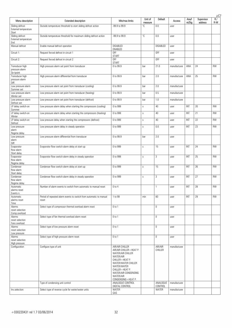
R-W Sliding defrost External temperature Start
Outside temperature threshold to start sliding defrost action -99.9 to 99.9 °C 0.0 user
Sliding defrost External temperature End
Outside temperature threshold for maximum sliding defrost action -99.9 to 99.9 °C 0.0 user
Manual defrost Enable manual defrost operation DISABLEDENABLED
DISABLED user
Circuit 1: Request forced defrost in circuit 1 OFFSTART
OFF user
Circuit 2: Request forced defrost in circuit 2 OFFSTART
OFF user
Transducer high pressure alarm Se tpoint
High pressure alarm set point from transducer 0 to 99.9 bar 21.0 manufacturer ANA 24 RW
Transducer high pressure alarm Diff.
High pressure alarm differential from transducer 0 to 99.9 bar 2.0 manufacturer ANA 25 RW
Low pressure alarm Summer set
Low pressure alarm set point from transducer (cooling) 0 to 99.9 bar 2.0 manufacturer
Low pressure alarm Winter set
Low pressure alarm set point from transducer (heating) 0 to 99.9 bar 0.5 manufacturer
Low pressure alarm Defrost set
Low pressure alarm set point from transducer (defrost) 0 to 99.9 bar 1.0 manufacturer
LP delay switch-on Summer
Low pressure alarm delay when starting the compressors (cooling) 0 to 999 s 40 user INT 20 RW
LP delay switch-on Winter
Low pressure alarm delay when starting the compressors (heating) 0 to 999 s 40 user INT 21 RW
LP delay switch-on Defrost
Low pressure delay when starting the compressors (defrost) 0 to 999 s 40 user INT 22 RW
Low pressure alarm Regime delay
Low pressure alarm delay in steady operation 0 to 999 s 0.0 user INT 23 RW
Low pressure alarm Diff.
Low pressure alarm differential from transducer 0 to 99.9 bar 2.0 user
Evaporator flow alarm Start delay
Evaporator flow switch alarm delay at start-up 0 to 999 s 15 user INT 24 RW
Evaporator flow alarm Regime delay
Evaporator flow switch alarm delay in steady operation 0 to 999 s 3 user INT 25 RW
Condenser flow alarm Start delay
Condenser flow switch alarm delay at start-up 0 to 999 s 15 user INT 26 RW
Condenser flow alarm Regime delay
Condenser flow switch alarm delay in steady operation 0 to 999 s 3 user INT 27 RW
Automatic alarms reset Events n.
Number of alarm events to switch from automatic to manual reset 0 to 4 1 user INT 28 RW
Automatic alarms reset Time
Period of repeated alarm events to switch from automatic to manual reset
1 to 99 min 60 user INT 29 RW
Alarms reset selection Comp.overload
Select type of compressor thermal overload alarm reset 0 to 1 0 user
Alarms reset selection Fans overload
Select type of fan thermal overload alarm reset 0 to 1 0 user
Alarms reset selection Low pressure
Select type of low pressure alarm reset 0 to 1 0 user
Alarms reset selection High pressure
Select type of high pressure alarm reset 0 to 1 0 user
Configuration Configure type of unit AIR/AIR CHILLERAIR/AIR CHILLER+HEAT P.WATER/AIR CHILLER WATER/AIR CHILLER+HEAT P. WATER/WATER CHILLER WATER/WATER CHILLER+HEAT P. WATER/AIR CONDENSINGWATER/AIR CONDENSING+HEAT P.
AIR/AIR CHILLER
manufacturer
Type of condensing unit control ANALOGUE CONTROLDIGITAL CONTROL
ANALOGUE CONTROL
manufacturer
Inv.selection: Select type of reverse cycle for water/water units WATERGAS
WATER manufacturer
μC3
+030220431 rel 1.7 03/06/2014 33
Menu description Extended description Min/max limits Unit of measure
Default Access Ana/I
nt/DigSupervisor
address R /
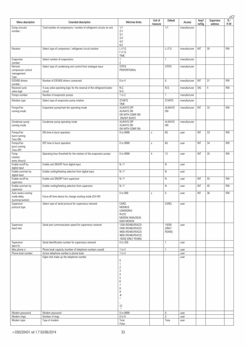
R-W Comp./circuits number:
Total number of compressors / number of refrigerant circuits on unit 1/12/1 3/1 2/2 4/2 6/2
1/1 manufacturer
Rotation Select type of compressor / refrigerant circuit rotation L.I.F.O.F.I.F.O. TIME
L.I.F.O. manufacturer INT 30 RW
Evaporator number:
Select number of evaporators 12
1 manufacturer
Remote compressor control management Type
Select type of condensing unit control from analogue input STEPSPROPORTIONAL
STEPS manufacturer
EVD400 drivers number:
Number of EVD400 drivers connected 0 to 4 0 manufacturer INT 31 RW
Reversal cycle valve logic
4-way valve operating logic for the reversal of the refrigerant/water circuit
N.C.N.O.
N.O. manufacturer DIG 4 RW
Pumps number: Number of evaporator pumps 1 to 2 1 manufacturer
Rotation type Select type of evaporator pump rotation STARTSTIME
STARTS manufacturer
Pumps/Fan running mode
Evaporator pump/main fan operating mode ALWAYS OFFALWAYS ON ON WITH COMP.ON ON/OFF BURST
ALWAYS ON
manufacturer INT 32 RW
Condenser pump running mode
Condenser pump operating mode ALWAYS OFFALWAYS ON ON WITH COMP.ON
ALWAYS ON
manufacturer
Pumps/Fan burst running Time ON:
ON time in burst operation 0 to 9999 s 60 user INT 33 RW
Pumps/Fan burst running Time OFF:
OFF time in burst operation 0 to 9999 s 60 user INT 34 RW
Pump rotation every (hours):
Operating hour threshold for the rotation of the evaporator pumps 0 to 9999 h 12 user INT 35 RW
Enable on/off by digital input
Enable unit ON/OFF from digital input N / Y N user
Enable sum/win by digital input
Enable cooling/heating selection from digital input N / Y N user
Enable on/off by supervisor
Enable unit ON/OFF from supervisor N / Y N user INT 55 RW
Enable sum/win by supervisor
Enable cooling/heating selection from supervisor N / Y N user INT 45 RW
Auto revers.running mode delay (summer/winter)
Force-off time device for change working mode (CH-HP)
0 to 999 s 0 user INT 36 RW
Supervisor protocol type
Select type of serial protocol for supervisory network CARELMODBUS LONWORKS Rs232 MODEM ANALOGUE. GSM MODEM
CAREL user
Supervisor baud rate
Serial port communication speed for supervisory network 1200 (RS485/RS422)2400 (RS485/RS422) 4800 (RS485/RS422) 9600 (RS485/RS422) 19200 (ONLY RS485)
19200 (ONLY RS485)
user
Supervisor Ident N.:
Serial identification number for supervisory network 0 to 200 1 user
Max.phone n.: Phone book capacity (number of telephone numbers saved) 1 to 4 1 user Phone book number: Active telephone number in phone book 1 to 4 user Digits that make up the telephone number
0 1 2 3 4 5 6 7 8 9 # * , @ ^
user
Modem password: Modem password 0 to 9999 0 user Modem rings: Number of rings 0 to 9 3 user Modem type: Type of modem Tone
Pulse Tone user
μC3
+030220431 rel 1.7 03/06/2014 34
Menu description Extended description Min/max limits Unit of measure
Default Access Ana/I
nt/DigSupervisor
address R /
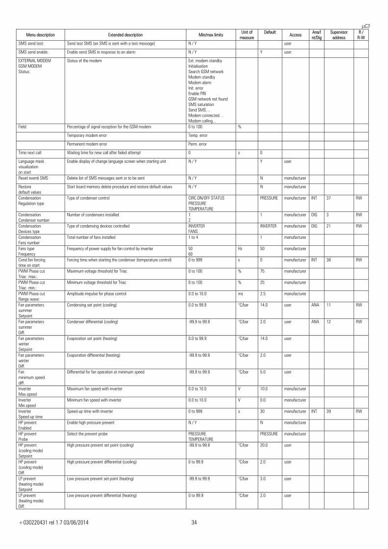
R-W SMS send test: Send test SMS (an SMS is sent with a test message) N / Y user
SMS send enable: Enable send SMS in response to an alarm N / Y Y user
EXTERNAL MODEM GSM MODEM Status:
Status of the modem Ext. modem standbyInitialisation Search GSM network Modem standby Modem alarm Init. error Enable PIN GSM network not found SMS saturation Send SMS… Modem connected… Modem calling...
Field: Percentage of signal reception for the GSM modem 0 to 100 %
Temporary modem error Temp. error
Permanent modem error Perm. error
Time next call Waiting time for new call after failed attempt 0 s 0
Language mask visualization on start
Enable display of change language screen when starting unit N / Y Y user
Reset eventi SMS Delete list of SMS messages sent or to be sent N / Y N manufacturer
Restore default values
Start board memory delete procedure and restore default values N / Y N manufacturer
Condensation Regulation type
Type of condenser control CIRC.ON/OFF STATUS PRESSURE TEMPERATURE
PRESSURE manufacturer INT 37 RW
Condensation Condenser number
Number of condensers installed 12
1 manufacturer DIG 3 RW
Condensation Devices type
Type of condensing devices controlled INVERTERFANS
INVERTER manufacturer DIG 21 RW
Condensation Fans number
Total number of fans installed 1 to 4 1 manufacturer
Fans type Frequency
Frequency of power supply for fan control by inverter 5060
Hz 50 manufacturer
Cond.fan forcing time on start
Forcing time when starting the condenser (temperature control) 0 to 999 s 0 manufacturer INT 38 RW
PWM Phase cut Triac max.:
Maximum voltage threshold for Triac 0 to 100 % 75 manufacturer
PWM Phase cut Triac min.:
Minimum voltage threshold for Triac 0 to 100 % 25 manufacturer
PWM Phase cut Range wave:
Amplitude impulse for phase control 0.0 to 10.0 ms 2.5 manufacturer
Fan parameters summer Setpoint
Condensing set point (cooling) 0.0 to 99.9 °C/bar 14.0 user ANA 11 RW
Fan parameters summer Diff.
Condenser differential (cooling) -99.9 to 99.9 °C/bar 2.0 user ANA 12 RW
Fan parameters winter Setpoint
Evaporation set point (heating) 0.0 to 99.9 °C/bar 14.0 user
Fan parameters winter Diff.
Evaporation differential (heating) -99.9 to 99.9 °C/bar 2.0 user
Fan minimum speed diff.
Differential for fan operation at minimum speed -99.9 to 99.9 °C/bar 5.0 user
Inverter Max.speed
Maximum fan speed with inverter 0.0 to 10.0 V 10.0 manufacturer
Inverter Min.speed
Minimum fan speed with inverter 0.0 to 10.0 V 0.0 manufacturer
Inverter Speed-up time
Speed-up time with inverter 0 to 999 s 30 manufacturer INT 39 RW
HP prevent Enabled
Enable high pressure prevent N / Y N manufacturer
HP prevent Probe
Select the prevent probe PRESSURETEMPERATURE
PRESSURE manufacturer
HP prevent (cooling mode) Setpoint
High pressure prevent set point (cooling) -99.9 to 99.9 °C/bar 20.0 user
HP prevent (cooling mode) Diff.
High pressure prevent differential (cooling) 0 to 99.9 °C/bar 2.0 user
LP prevent (heating mode) Setpoint
Low pressure prevent set point (heating) -99.9 to 99.9 °C/bar 3.0 user
LP prevent (heating mode) Diff.
Low pressure prevent differential (heating) 0 to 99.9 °C/bar 2.0 user
μC3
+030220431 rel 1.7 03/06/2014 35
Menu description Extended description Min/max limits Unit of measure
Default Access Ana/I
nt/DigSupervisor
address R /
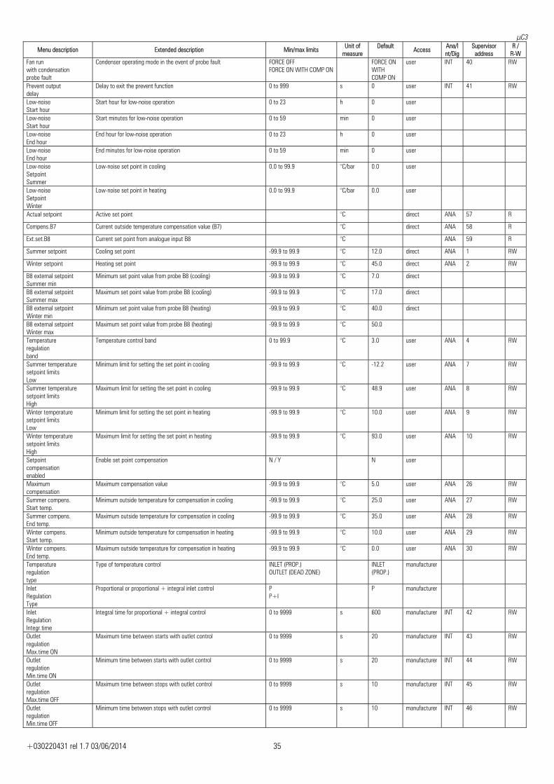
R-W Fan run with condensation probe fault
Condenser operating mode in the event of probe fault FORCE OFFFORCE ON WITH COMP ON
FORCE ON WITH COMP ON
user INT 40 RW
Prevent output delay
Delay to exit the prevent function 0 to 999 s 0 user INT 41 RW
Low-noise Start hour
Start hour for low-noise operation 0 to 23 h 0 user
Low-noise Start hour
Start minutes for low-noise operation 0 to 59 min 0 user
Low-noise End hour
End hour for low-noise operation 0 to 23 h 0 user
Low-noise End hour
End minutes for low-noise operation 0 to 59 min 0 user
Low-noise Setpoint Summer
Low-noise set point in cooling 0.0 to 99.9 °C/bar 0.0 user
Low-noise Setpoint Winter
Low-noise set point in heating 0.0 to 99.9 °C/bar 0.0 user
Actual setpoint Active set point °C direct ANA 57 R
Compens.B7 Current outside temperature compensation value (B7) °C direct ANA 58 R
Ext.set.B8 Current set point from analogue input B8 °C ANA 59 R
Summer setpoint Cooling set point -99.9 to 99.9 °C 12.0 direct ANA 1 RW
Winter setpoint Heating set point -99.9 to 99.9 °C 45.0 direct ANA 2 RW
B8 external setpoint Summer min
Minimum set point value from probe B8 (cooling) -99.9 to 99.9 °C 7.0 direct
B8 external setpoint Summer max
Maximum set point value from probe B8 (cooling) -99.9 to 99.9 °C 17.0 direct
B8 external setpoint Winter min
Minimum set point value from probe B8 (heating) -99.9 to 99.9 °C 40.0 direct
B8 external setpoint Winter max
Maximum set point value from probe B8 (heating) -99.9 to 99.9 °C 50.0
Temperature regulation band
Temperature control band 0 to 99.9 °C 3.0 user ANA 4 RW
Summer temperature setpoint limits Low
Minimum limit for setting the set point in cooling -99.9 to 99.9 °C -12.2 user ANA 7 RW
Summer temperature setpoint limits High
Maximum limit for setting the set point in cooling -99.9 to 99.9 °C 48.9 user ANA 8 RW
Winter temperature setpoint limits Low
Minimum limit for setting the set point in heating -99.9 to 99.9 °C 10.0 user ANA 9 RW
Winter temperature setpoint limits High
Maximum limit for setting the set point in heating -99.9 to 99.9 °C 93.0 user ANA 10 RW
Setpoint compensation enabled
Enable set point compensation N / Y N user
Maximum compensation
Maximum compensation value -99.9 to 99.9 °C 5.0 user ANA 26 RW
Summer compens. Start temp.
Minimum outside temperature for compensation in cooling -99.9 to 99.9 °C 25.0 user ANA 27 RW
Summer compens. End temp.
Maximum outside temperature for compensation in cooling -99.9 to 99.9 °C 35.0 user ANA 28 RW
Winter compens. Start temp.
Minimum outside temperature for compensation in heating -99.9 to 99.9 °C 10.0 user ANA 29 RW
Winter compens. End temp.
Maximum outside temperature for compensation in heating -99.9 to 99.9 °C 0.0 user ANA 30 RW
Temperature regulation type
Type of temperature control INLET (PROP.)OUTLET (DEAD ZONE)
INLET (PROP.)
manufacturer
Inlet Regulation Type
Proportional or proportional + integral inlet control PP+I
P manufacturer
Inlet Regulation Integr.time
Integral time for proportional + integral control 0 to 9999 s 600 manufacturer INT 42 RW
Outlet regulation Max.time ON
Maximum time between starts with outlet control 0 to 9999 s 20 manufacturer INT 43 RW
Outlet regulation Min.time ON
Minimum time between starts with outlet control 0 to 9999 s 20 manufacturer INT 44 RW
Outlet regulation Max.time OFF
Maximum time between stops with outlet control 0 to 9999 s 10 manufacturer INT 45 RW
Outlet regulation Min.time OFF
Minimum time between stops with outlet control 0 to 9999 s 10 manufacturer INT 46 RW
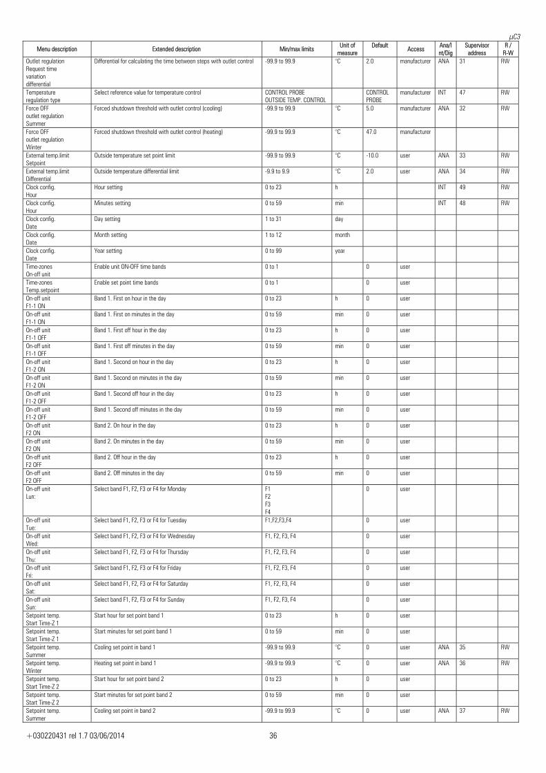
μC3
+030220431 rel 1.7 03/06/2014 36
Menu description Extended description Min/max limits Unit of measure
Default Access Ana/I
nt/DigSupervisor
address R /
R-W Outlet regulation Request time variation differential
Differential for calculating the time between steps with outlet control -99.9 to 99.9 °C 2.0 manufacturer ANA 31 RW
Temperature regulation type
Select reference value for temperature control CONTROL PROBEOUTSIDE TEMP. CONTROL
CONTROL PROBE
manufacturer INT 47 RW
Force OFF outlet regulation Summer
Forced shutdown threshold with outlet control (cooling) -99.9 to 99.9 °C 5.0 manufacturer ANA 32 RW
Force OFF outlet regulation Winter
Forced shutdown threshold with outlet control (heating) -99.9 to 99.9 °C 47.0 manufacturer
External temp.limit Setpoint
Outside temperature set point limit -99.9 to 99.9 °C -10.0 user ANA 33 RW
External temp.limit Differential
Outside temperature differential limit -9.9 to 9.9 °C 2.0 user ANA 34 RW
Clock config. Hour
Hour setting 0 to 23 h INT 49 RW
Clock config. Hour
Minutes setting 0 to 59 min INT 48 RW
Clock config. Date
Day setting 1 to 31 day
Clock config. Date
Month setting 1 to 12 month
Clock config. Date
Year setting 0 to 99 year
Time-zones On-off unit
Enable unit ON-OFF time bands 0 to 1 0 user
Time-zones Temp.setpoint
Enable set point time bands 0 to 1 0 user
On-off unit F1-1 ON
Band 1. First on hour in the day 0 to 23 h 0 user
On-off unit F1-1 ON
Band 1. First on minutes in the day 0 to 59 min 0 user
On-off unit F1-1 OFF
Band 1. First off hour in the day 0 to 23 h 0 user
On-off unit F1-1 OFF
Band 1. First off minutes in the day 0 to 59 min 0 user
On-off unit F1-2 ON
Band 1. Second on hour in the day 0 to 23 h 0 user
On-off unit F1-2 ON
Band 1. Second on minutes in the day 0 to 59 min 0 user
On-off unit F1-2 OFF
Band 1. Second off hour in the day 0 to 23 h 0 user
On-off unit F1-2 OFF
Band 1. Second off minutes in the day 0 to 59 min 0 user
On-off unit F2 ON
Band 2. On hour in the day 0 to 23 h 0 user
On-off unit F2 ON
Band 2. On minutes in the day 0 to 59 min 0 user
On-off unit F2 OFF
Band 2. Off hour in the day 0 to 23 h 0 user
On-off unit F2 OFF
Band 2. Off minutes in the day 0 to 59 min 0 user
On-off unit Lun:
Select band F1, F2, F3 or F4 for Monday F1F2 F3 F4
0 user
On-off unit Tue:
Select band F1, F2, F3 or F4 for Tuesday F1,F2,F3,F4 0 user
On-off unit Wed:
Select band F1, F2, F3 or F4 for Wednesday F1, F2, F3, F4 0 user
On-off unit Thu:
Select band F1, F2, F3 or F4 for Thursday F1, F2, F3, F4 0 user
On-off unit Fri:
Select band F1, F2, F3 or F4 for Friday F1, F2, F3, F4 0 user
On-off unit Sat:
Select band F1, F2, F3 or F4 for Saturday F1, F2, F3, F4 0 user
On-off unit Sun:
Select band F1, F2, F3 or F4 for Sunday F1, F2, F3, F4 0 user
Setpoint temp. Start Time-Z 1
Start hour for set point band 1 0 to 23 h 0 user
Setpoint temp. Start Time-Z 1
Start minutes for set point band 1 0 to 59 min 0 user
Setpoint temp. Summer
Cooling set point in band 1 -99.9 to 99.9 °C 0 user ANA 35 RW
Setpoint temp. Winter
Heating set point in band 1 -99.9 to 99.9 °C 0 user ANA 36 RW
Setpoint temp. Start Time-Z 2
Start hour for set point band 2 0 to 23 h 0 user
Setpoint temp. Start Time-Z 2
Start minutes for set point band 2 0 to 59 min 0 user
Setpoint temp. Summer
Cooling set point in band 2 -99.9 to 99.9 °C 0 user ANA 37 RW
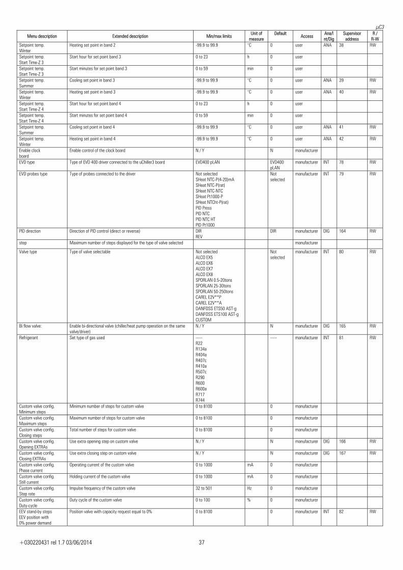
μC3
+030220431 rel 1.7 03/06/2014 37
Menu description Extended description Min/max limits Unit of measure
Default Access Ana/I
nt/DigSupervisor
address R /
R-W Setpoint temp. Winter
Heating set point in band 2 -99.9 to 99.9 °C 0 user ANA 38 RW
Setpoint temp. Start Time-Z 3
Start hour for set point band 3 0 to 23 h 0 user
Setpoint temp. Start Time-Z 3
Start minutes for set point band 3 0 to 59 min 0 user
Setpoint temp. Summer
Cooling set point in band 3 -99.9 to 99.9 °C 0 user ANA 39 RW
Setpoint temp. Winter
Heating set point in band 3 -99.9 to 99.9 °C 0 user ANA 40 RW
Setpoint temp. Start Time-Z 4
Start hour for set point band 4 0 to 23 h 0 user
Setpoint temp. Start Time-Z 4
Start minutes for set point band 4 0 to 59 min 0 user
Setpoint temp. Summer
Cooling set point in band 4 -99.9 to 99.9 °C 0 user ANA 41 RW
Setpoint temp. Winter
Heating set point in band 4 -99.9 to 99.9 °C 0 user ANA 42 RW
Enable clock board
Enable control of the clock board N / Y N manufacturer
EVD type Type of EVD 400 driver connected to the uChiller3 board EVD400 pLAN EVD400 pLAN
manufacturer INT 78 RW
EVD probes type Type of probes connected to the driver Not selectedSHeat NTC-P(4-20)mA SHeat NTC-P(rat) SHeat NTC-NTC SHeat Pt1000-P SHeat NTCht-P(rat) PID Press PID NTC PID NTC HT PID Pt1000
Not selected
manufacturer INT 79 RW
PID direction Direction of PID control (direct or reverse) DIRREV
DIR manufacturer DIG 164 RW
step Maximum number of steps displayed for the type of valve selected manufacturer
Valve type Type of valve selectable Not selectedALCO EX5 ALCO EX6 ALCO EX7 ALCO EX8 SPORLAN 0.5-20tons SPORLAN 25-30tons SPORLAN 50-250tons CAREL E2V**P CAREL E2V**A DANFOSS ETS50 AST-g DANFOSS ETS100 AST-g CUSTOM
Not selected
manufacturer INT 80 RW
Bi flow valve: Enable bi-directional valve (chiller/heat pump operation on the same valve/driver)
N / Y N manufacturer DIG 165 RW
Refrigerant Set type of gas used -----R22 R134a R404a R407c R410a R507c R290 R600 R600a R717 R744
----- manufacturer INT 81 RW
Custom valve config. Minimum steps
Minimum number of steps for custom valve 0 to 8100 0 manufacturer
Custom valve config. Maximum steps
Maximum number of steps for custom valve 0 to 8100 0 manufacturer
Custom valve config. Closing steps
Total number of steps for custom valve 0 to 8100 0 manufacturer
Custom valve config. Opening EXTRAs
Use extra opening step on custom valve N / Y N manufacturer DIG 166 RW
Custom valve config. Closing EXTRAs
Use extra closing step on custom valve N / Y N manufacturer DIG 167 RW
Custom valve config. Phase current
Operating current of the custom valve 0 to 1000 mA 0 manufacturer
Custom valve config. Still current
Holding current of the custom valve 0 to 1000 mA 0 manufacturer
Custom valve config. Step rate
Impulse frequency of the custom valve 32 to 501 Hz 0 manufacturer
Custom valve config. Duty-cycle
Duty cycle of the custom valve 0 to 100 % 0 manufacturer
EEV stand-by steps EEV position with 0% power demand
Position valve with capacity request equal to 0% 0 to 8100 0 manufacturer INT 82 RW
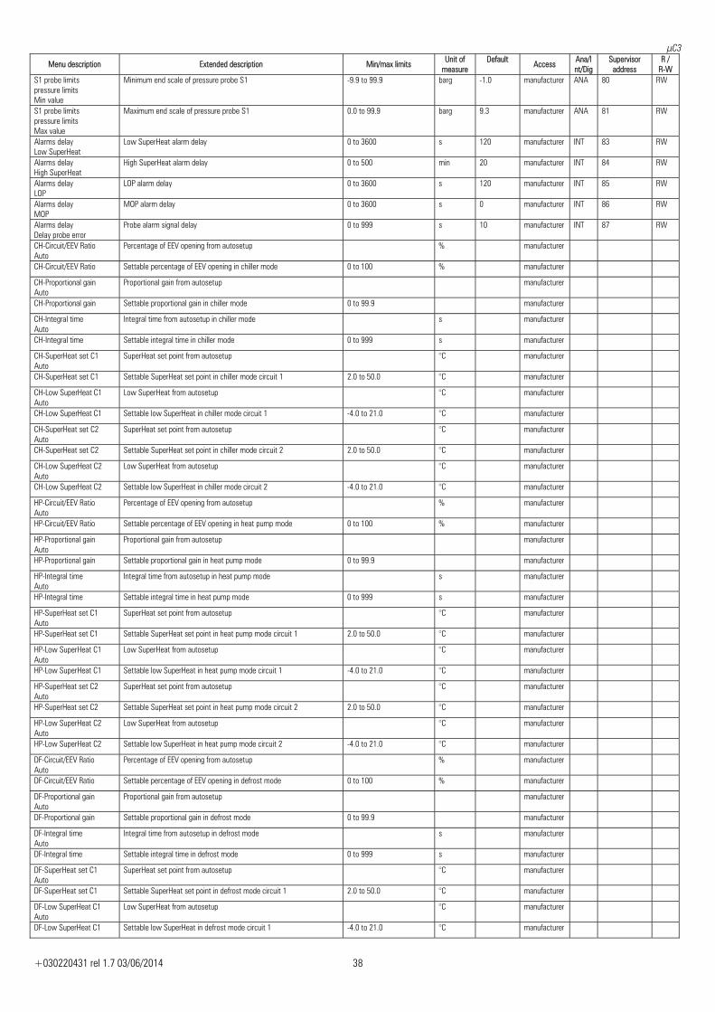
μC3
+030220431 rel 1.7 03/06/2014 38
Menu description Extended description Min/max limits Unit of measure
Default Access Ana/I
nt/DigSupervisor
address R /
R-W S1 probe limits pressure limits Min value
Minimum end scale of pressure probe S1 -9.9 to 99.9 barg -1.0 manufacturer ANA 80 RW
S1 probe limits pressure limits Max value
Maximum end scale of pressure probe S1 0.0 to 99.9 barg 9.3 manufacturer ANA 81 RW
Alarms delay Low SuperHeat
Low SuperHeat alarm delay 0 to 3600 s 120 manufacturer INT 83 RW
Alarms delay High SuperHeat
High SuperHeat alarm delay 0 to 500 min 20 manufacturer INT 84 RW
Alarms delay LOP
LOP alarm delay 0 to 3600 s 120 manufacturer INT 85 RW
Alarms delay MOP
MOP alarm delay 0 to 3600 s 0 manufacturer INT 86 RW
Alarms delay Delay probe error
Probe alarm signal delay 0 to 999 s 10 manufacturer INT 87 RW
CH-Circuit/EEV Ratio Auto
Percentage of EEV opening from autosetup % manufacturer
CH-Circuit/EEV Ratio Settable percentage of EEV opening in chiller mode 0 to 100 % manufacturer
CH-Proportional gain Auto
Proportional gain from autosetup manufacturer
CH-Proportional gain Settable proportional gain in chiller mode 0 to 99.9 manufacturer
CH-Integral time Auto
Integral time from autosetup in chiller mode s manufacturer
CH-Integral time Settable integral time in chiller mode 0 to 999 s manufacturer
CH-SuperHeat set C1 Auto
SuperHeat set point from autosetup °C manufacturer
CH-SuperHeat set C1 Settable SuperHeat set point in chiller mode circuit 1 2.0 to 50.0 °C manufacturer
CH-Low SuperHeat C1 Auto
Low SuperHeat from autosetup °C manufacturer
CH-Low SuperHeat C1 Settable low SuperHeat in chiller mode circuit 1 -4.0 to 21.0 °C manufacturer
CH-SuperHeat set C2 Auto
SuperHeat set point from autosetup °C manufacturer
CH-SuperHeat set C2 Settable SuperHeat set point in chiller mode circuit 2 2.0 to 50.0 °C manufacturer
CH-Low SuperHeat C2 Auto
Low SuperHeat from autosetup °C manufacturer
CH-Low SuperHeat C2 Settable low SuperHeat in chiller mode circuit 2 -4.0 to 21.0 °C manufacturer
HP-Circuit/EEV Ratio Auto
Percentage of EEV opening from autosetup % manufacturer
HP-Circuit/EEV Ratio Settable percentage of EEV opening in heat pump mode 0 to 100 % manufacturer
HP-Proportional gain Auto
Proportional gain from autosetup manufacturer
HP-Proportional gain Settable proportional gain in heat pump mode 0 to 99.9 manufacturer
HP-Integral time Auto
Integral time from autosetup in heat pump mode s manufacturer
HP-Integral time Settable integral time in heat pump mode 0 to 999 s manufacturer
HP-SuperHeat set C1 Auto
SuperHeat set point from autosetup °C manufacturer
HP-SuperHeat set C1 Settable SuperHeat set point in heat pump mode circuit 1 2.0 to 50.0 °C manufacturer
HP-Low SuperHeat C1 Auto
Low SuperHeat from autosetup °C manufacturer
HP-Low SuperHeat C1 Settable low SuperHeat in heat pump mode circuit 1 -4.0 to 21.0 °C manufacturer
HP-SuperHeat set C2 Auto
SuperHeat set point from autosetup °C manufacturer
HP-SuperHeat set C2 Settable SuperHeat set point in heat pump mode circuit 2 2.0 to 50.0 °C manufacturer
HP-Low SuperHeat C2 Auto
Low SuperHeat from autosetup °C manufacturer
HP-Low SuperHeat C2 Settable low SuperHeat in heat pump mode circuit 2 -4.0 to 21.0 °C manufacturer
DF-Circuit/EEV Ratio Auto
Percentage of EEV opening from autosetup % manufacturer
DF-Circuit/EEV Ratio Settable percentage of EEV opening in defrost mode 0 to 100 % manufacturer
DF-Proportional gain Auto
Proportional gain from autosetup manufacturer
DF-Proportional gain Settable proportional gain in defrost mode 0 to 99.9 manufacturer
DF-Integral time Auto
Integral time from autosetup in defrost mode s manufacturer
DF-Integral time Settable integral time in defrost mode 0 to 999 s manufacturer
DF-SuperHeat set C1 Auto
SuperHeat set point from autosetup °C manufacturer
DF-SuperHeat set C1 Settable SuperHeat set point in defrost mode circuit 1 2.0 to 50.0 °C manufacturer
DF-Low SuperHeat C1 Auto
Low SuperHeat from autosetup °C manufacturer
DF-Low SuperHeat C1 Settable low SuperHeat in defrost mode circuit 1 -4.0 to 21.0 °C manufacturer
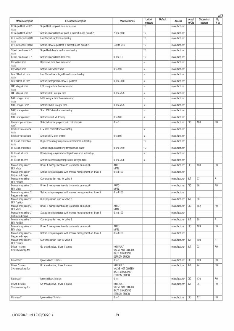
μC3
+030220431 rel 1.7 03/06/2014 39
Menu description Extended description Min/max limits Unit of measure
Default Access Ana/I
nt/DigSupervisor
address R /
R-W DF-SuperHeat set C2 Auto
SuperHeat set point from autosetup °C manufacturer
DF-SuperHeat set C2 Settable SuperHeat set point in defrost mode circuit 2 2.0 to 50.0 °C manufacturer
DF-Low SuperHeat C2 Auto
Low SuperHeat from autosetup °C manufacturer
DF-Low SuperHeat C2 Settable low SuperHeat in defrost mode circuit 2 -4.0 to 21.0 °C manufacturer
SHeat dead zone +/- Auto
SuperHeat dead zone from autosetup °C manufacturer
SHeat dead zone +/- Settable SuperHeat dead zone 0.0 to 9.9 °C manufacturer
Derivative time Auto
Derivative time from autosetup s manufacturer
Derivative time Settable derivative time 0 to 999 s manufacturer
Low SHeat int.time Auto
Low SuperHeat integral time from autosetup s manufacturer
Low SHeat int.time Settable integral time low SuperHeat 0.0 to 30.0 s manufacturer
LOP integral time Auto
LOP integral time from autosetup s manufacturer
LOP integral time Settable LOP integral time 0.0 to 25.5 s manufacturer
MOP integral time Auto
MOP integral time from autosetup s manufacturer
MOP integral time Settable MOP integral time 0.0 to 25.5 s manufacturer
MOP startup delay Auto
Start MOP delay from autosetup s manufacturer
MOP startup delay Settable start MOP delay 0 to 500 s manufacturer
Dynamic proportional gain?
Select dynamic proportional control mode 0 to 1 manufacturer DIG 168 RW
Blocked valve check Auto
EEV stop control from autosetup s manufacturer
Blocked valve check Settable EEV stop control 0 to 999 s manufacturer
Hi TCond.protection Auto
High condensing temperature alarm from autosetup °C manufacturer
Hi TCond.protection Settable high condensing temperature alarm 0.0 to 99.9 °C manufacturer
Hi TCond.int.time Auto
Condensing temperature integral time from autosetup s manufacturer
Hi TCond.int.time Settable condensing temperature integral time 0.0 to 25.5 s manufacturer
Manual mng.driver 1 EEV Mode
Driver 1 management mode (automatic or manual) AUTOMAN.
manufacturer DIG 160 RW
Manual mng.driver 1 Requested steps
Settable steps required with manual management on driver 1 0 to 8100 manufacturer
Manual mng.driver 1 EEV Position
Current position read for valve 1 manufacturer INT 97 R
Manual mng.driver 2 EEV Mode
Driver 2 management mode (automatic or manual) AUTOMAN.
manufacturer DIG 161 RW
Manual mng.driver 2 Requested steps
Settable steps required with manual management on driver 2 0 to 8100 manufacturer
Manual mng.driver 2 EEV Position
Current position read for valve 2 manufacturer INT 98 R
Manual mng.driver 3 EEV Mode
Driver 3 management mode (automatic or manual) AUTOMAN.
manufacturer DIG 162 RW
Manual mng.driver 3 Requested steps
Settable steps required with manual management on driver 3 0 to 8100 manufacturer
Manual mng.driver 3 EEV Position
Current position read for valve 3 manufacturer INT 99 R
Manual mng.driver 4 EEV Mode
Driver 4 management mode (automatic or manual) AUTOMAN.
manufacturer DIG 163 RW
Manual mng.driver 4 Requested steps
Settable steps required with manual management on driver 4 0 to 8100 manufacturer
Manual mng.driver 4 EEV Position
Current position read for valve 4 manufacturer INT 100 R
Driver 1 status System waiting for
Go ahead active, driver 1 status NO FAULTVALVE NOT CLOSED BATT. CHARGING EEPROM ERROR
manufacturer INT 93 RW
Go ahead? Ignore driver 1 status 0 to 1 manufacturer DIG 169 RW
Driver 2 status System waiting for
Go ahead active, driver 2 status NO FAULTVALVE NOT CLOSED BATT. CHARGING EEPROM ERROR
manufacturer INT 94 RW
Go ahead? Ignore driver 2 status 0 to 1 manufacturer DIG 170 RW
Driver 3 status System waiting for
Go ahead active, driver 3 status NO FAULTVALVE NOT CLOSED BATT. CHARGING EEPROM ERROR
manufacturer INT 95 RW
Go ahead? Ignore driver 3 status 0 to 1 manufacturer DIG 171 RW
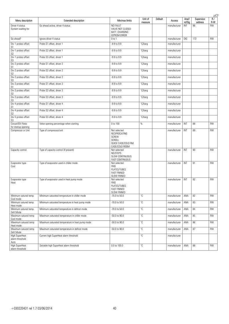
μC3
+030220431 rel 1.7 03/06/2014 40
Menu description Extended description Min/max limits Unit of measure
Default Access Ana/I
nt/DigSupervisor
address R /
R-W Driver 4 status System waiting for
Go ahead active, driver 4 status NO FAULTVALVE NOT CLOSED BATT. CHARGING EEPROM ERROR
manufacturer INT 96 RW
Go ahead? Ignore driver 4 status 0 to 1 manufacturer DIG 172 RW
Drv 1 probes offset S1
Probe S1 offset, driver 1 -9.9 to 9.9 °C/barg manufacturer
Drv 1 probes offset S2
Probe S2 offset, driver 1 -9.9 to 9.9 °C/barg manufacturer
Drv 1 probes offset S3
Probe S3 offset, driver 1 -9.9 to 9.9 °C/barg manufacturer
Drv 2 probes offset S1
Probe S1 offset, driver 2 -9.9 to 9.9 °C/barg manufacturer
Drv 2 probes offset S2
Probe S2 offset, driver 2 -9.9 to 9.9 °C/barg manufacturer
Drv 2 probes offset S3
Probe S3 offset, driver 2 -9.9 to 9.9 °C/barg manufacturer
Drv 3 probes offset S1
Probe S1 offset, driver 3 -9.9 to 9.9 °C/barg manufacturer
Drv 3 probes offset S2
Probe S2 offset, driver 3 -9.9 to 9.9 °C/barg manufacturer
Drv 3 probes offset S3
Probe S3 offset, driver 3 -9.9 to 9.9 °C/barg manufacturer
Drv 4 probes offset S1
Probe S1 offset, driver 4 -9.9 to 9.9 °C/barg manufacturer
Drv 4 probes offset S2
Probe S2 offset, driver 4 -9.9 to 9.9 °C/barg manufacturer
Drv 5 probes offset S3
Probe S3 offset, driver 4 -9.9 to 9.9 °C/barg manufacturer
Circuit/EEV Ratio for startup opening
Valve opening percentage when starting 0 to 100 % manufacturer INT 88 RW
Compressor or Unit Type of compressor/unit Not selectedRECIPROCATING SCREW SCROLL QUICK CASE/COLD RM. CASE/COLD ROOM
manufacturer INT 89 RW
Capacity control Type of capacity-control (if present) Not selectedNO/STEPS SLOW CONTINUOUS FAST CONTINUOUS
manufacturer INT 90 RW
Evaporator type Cool
Type of evaporator used in chiller mode Not selectedFINS PLATES/TUBES FAST FINNED SLOW FINNED
manufacturer INT 91 RW
Evaporator type Heat
Type of evaporator used in heat pump mode Not selectedFINS PLATES/TUBES FAST FINNED SLOW FINNED
manufacturer INT 92 RW
Minimum satured temp Cool mode
Minimum saturated temperature in chiller mode -70.0 to 50.0 °C manufacturer ANA 82 RW
Minimum satured temp Heat mode
Minimum saturated temperature in heat pump mode -70.0 to 50.0 °C manufacturer ANA 83 RW
Minimum satured temp Defr.Mode
Minimum saturated temperature in defrost mode -70.0 to 50.0 °C manufacturer ANA 84 RW
Maximum satured temp Cool mode
Maximum saturated temperature in chiller mode -50.0 to 90.0 °C manufacturer ANA 85 RW
Maximum satured temp Heat mode
Maximum saturated temperature in heat pump mode -50.0 to 90.0 °C manufacturer ANA 86 RW
Maximum satured temp Defr.Mode
Maximum saturated temperature in defrost mode -50.0 to 90.0 °C manufacturer ANA 87 RW
High SuperHeat alarm threshold Auto
Current high SuperHeat alarm threshold °C manufacturer
High SuperHeat alarm threshold
Settable high SuperHeat alarm threshold 0.0 to 100.0 °C manufacturer ANA 88 RW
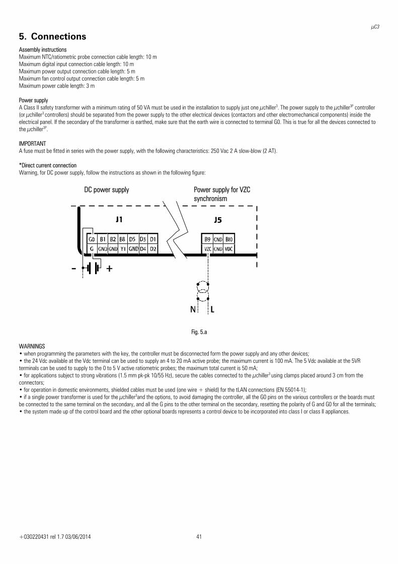
μC3
+030220431 rel 1.7 03/06/2014 41
5. Connections Assembly instructions Maximum NTC/ratiometric probe connection cable length: 10 m Maximum digital input connection cable length: 10 m Maximum power output connection cable length: 5 m Maximum fan control output connection cable length: 5 m Maximum power cable length: 3 m Power supply A Class II safety transformer with a minimum rating of 50 VA must be used in the installation to supply just one μchiller3. The power supply to the μchiller3P controller (or μchiller3 controllers) should be separated from the power supply to the other electrical devices (contactors and other electromechanical components) inside the electrical panel. If the secondary of the transformer is earthed, make sure that the earth wire is connected to terminal G0. This is true for all the devices connected to the μchiller3P. IMPORTANT A fuse must be fitted in series with the power supply, with the following characteristics: 250 Vac 2 A slow-blow (2 AT). *Direct current connection Warning, for DC power supply, follow the instructions as shown in the following figure:
Fig. 5.a WARNINGS • when programming the parameters with the key, the controller must be disconnected form the power supply and any other devices; • the 24 Vdc available at the Vdc terminal can be used to supply an 4 to 20 mA active probe; the maximum current is 100 mA. The 5 Vdc available at the 5VR terminals can be used to supply to the 0 to 5 V active ratiometric probes; the maximum total current is 50 mA; • for applications subject to strong vibrations (1.5 mm pk-pk 10/55 Hz), secure the cables connected to the μchiller3 using clamps placed around 3 cm from the connectors; • for operation in domestic environments, shielded cables must be used (one wire + shield) for the tLAN connections (EN 55014-1); • if a single power transformer is used for the μchiller3and the options, to avoid damaging the controller, all the G0 pins on the various controllers or the boards must be connected to the same terminal on the secondary, and all the G pins to the other terminal on the secondary, resetting the polarity of G and G0 for all the terminals; • the system made up of the control board and the other optional boards represents a control device to be incorporated into class I or class II appliances.
DC power supply Power supply for VZC synchronism
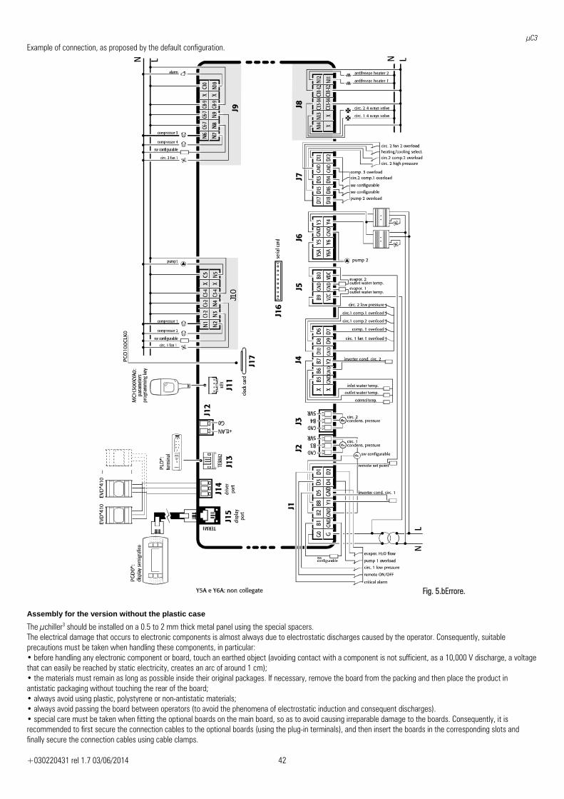
μC3
+030220431 rel 1.7 03/06/2014 42
Example of connection, as proposed by the default configuration.
J10
1D
58
21
GND
LNLN
pump 2
...
Fig. 5.bErrore.
Assembly for the version without the plastic case
The μchiller3 should be installed on a 0.5 to 2 mm thick metal panel using the special spacers. The electrical damage that occurs to electronic components is almost always due to electrostatic discharges caused by the operator. Consequently, suitable precautions must be taken when handling these components, in particular: • before handling any electronic component or board, touch an earthed object (avoiding contact with a component is not sufficient, as a 10,000 V discharge, a voltage that can easily be reached by static electricity, creates an arc of around 1 cm); • the materials must remain as long as possible inside their original packages. If necessary, remove the board from the packing and then place the product in antistatic packaging without touching the rear of the board; • always avoid using plastic, polystyrene or non-antistatic materials; • always avoid passing the board between operators (to avoid the phenomena of electrostatic induction and consequent discharges). • special care must be taken when fitting the optional boards on the main board, so as to avoid causing irreparable damage to the boards. Consequently, it is recommended to first secure the connection cables to the optional boards (using the plug-in terminals), and then insert the boards in the corresponding slots and finally secure the connection cables using cable clamps.
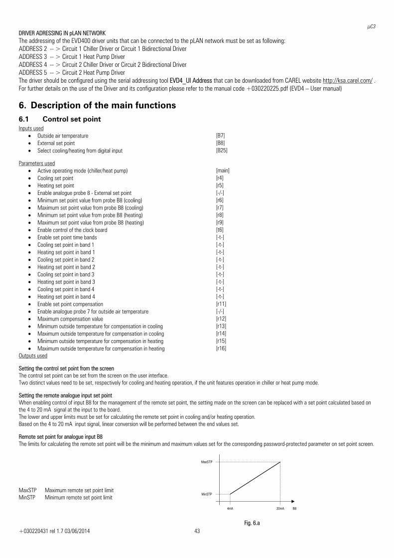
μC3
+030220431 rel 1.7 03/06/2014 43
DRIVER ADRESSING IN pLAN NETWORK The addressing of the EVD400 driver units that can be connected to the pLAN network must be set as following: ADDRESS 2 -- > Circuit 1 Chiller Driver or Circuit 1 Bidirectional Driver ADDRESS 3 -- > Circuit 1 Heat Pump Driver ADDRESS 4 -- > Circuit 2 Chiller Driver or Circuit 2 Bidirectional Driver ADDRESS 5 -- > Circuit 2 Heat Pump Driver The driver should be configured using the serial addressing tool EVD4_UI Address that can be downloaded from CAREL website http://ksa.carel.com/ . For further details on the use of the Driver and its configuration please refer to the manual code +030220225.pdf (EVD4 – User manual)
6. Description of the main functions 6.1 Control set point Inputs used
• Outside air temperature [B7] • External set point [B8] • Select cooling/heating from digital input [B25]
Parameters used
• Active operating mode (chiller/heat pump) [main]• Cooling set point [r4] • Heating set point [r5] • Enable analogue probe 8 - External set point [-/-] • Minimum set point value from probe B8 (cooling) [r6] • Maximum set point value from probe B8 (cooling) [r7] • Minimum set point value from probe B8 (heating) [r8] • Maximum set point value from probe B8 (heating) [r9] • Enable control of the clock board [t6] • Enable set point time bands [-t-] • Cooling set point in band 1 [-t-] • Heating set point in band 1 [-t-] • Cooling set point in band 2 [-t-] • Heating set point in band 2 [-t-] • Cooling set point in band 3 [-t-] • Heating set point in band 3 [-t-] • Cooling set point in band 4 [-t-] • Heating set point in band 4 [-t-] • Enable set point compensation [r11] • Enable analogue probe 7 for outside air temperature [-/-] • Maximum compensation value [r12] • Minimum outside temperature for compensation in cooling [r13] • Maximum outside temperature for compensation in cooling [r14] • Minimum outside temperature for compensation in heating [r15] • Maximum outside temperature for compensation in heating [r16]
Outputs used Setting the control set point from the screen The control set point can be set from the screen on the user interface. Two distinct values need to be set, respectively for cooling and heating operation, if the unit features operation in chiller or heat pump mode. Setting the remote analogue input set point When enabling control of input B8 for the management of the remote set point, the setting made on the screen can be replaced with a set point calculated based on the 4 to 20 mA signal at the input to the board. The lower and upper limits must be set for calculating the remote set point in cooling and/or heating operation. Based on the 4 to 20 mA input signal, linear conversion will be performed between the end values set. Remote set point for analogue input B8 The limits for calculating the remote set point will be the minimum and maximum values set for the corresponding password-protected parameter on set point screen.
B8 20mA 4mA
MinSTP
MaxSTP
MaxSTP Maximum remote set point limit MinSTP Minimum remote set point limit
Fig. 6.a

μC3
+030220431 rel 1.7 03/06/2014 44
Time bands for varying the set point By enabling control of the clock board, the management of 4 daily set point time bands can be configured. Each time band features the start and end time and the associated set point. When the time band starts, the active set point is replaced by the value set for the active time band, irrespective of whether the analogue input for the remote set point is activated.
Set point compensation for outside air temperature The working set point can be adjusted according to the outside air temperature. Normally this function is used in installations where greater priority is given to comfort; for example, in a shop where people enter and exit frequently, an excessive temperature difference between the inside and outside may be annoying to users and negative to their health.
This function increases or decreases the unit set point according to the outside temperature measured, adding an offset to set point set as described above that is directly proportional to the difference between the minimum and maximum limits.
The parameters for setting the operating limits are different for cooling and heating operation, without any restrictions regarding the setting of the limits for calculating the compensation offset.
6.1.1 Minimum outside temperature limit Inputs used
• Outside air temperature [B7] Parameters used
• Enable analogue probe 7 Outside air temperature [-/-] • Outside temperature set point limit [r17] • Outside temperature differential limit [r18]
Outputs used • Compressor 1 circuit 1
Winding A compressor 1 [B29]
• Compressor 2 circuit 1 Winding B compressor 1
[B30]
• Compressor 3 circuit 1 [B31]• Compressor 1 circuit 2. Winding A compressor 2 [B34]• Compressor 2 circuit 2. Winding B compressor 2 [B35]• Compressor 3 circuit 2 [B36]
If the probe for measuring the outside air temperature is enabled, a temperature threshold is activated below which the compressors are forced off. Temperature control only starts again when the outside air temperature is above the set point + a differential. On units in chiller operation, this is done to prevent the operation of the unit in ambient conditions that would cause an excessively low condensing pressure. On units in heat pump operation, this is done to prevent the operation of the unit in ambient conditions that would cause the rapid formation of frost on the outdoor exchanger. To disable the function, simply set the value of the control differential to 0.
6.2 Inlet-room temperature control Inputs used
• Room temperature (air/air units) Evaporator water inlet temperature
[B5]
Parameters used • Active operating mode (chiller/heat pump) [main]• Configure type of unit [-H-] • Total number of compressors / number of refrigerant circuits on unit [-H-] • Enable compressor capacity control [-c-] • Type of temperature control [-r-] • Active set point [r1] • Temperature control band [r10] • Proportional or proportional + integral · Inlet control [-r-] • Integral time for proportional + integral control [-r-]
Outputs used • Liquid solenoid circuit 1 [B31] • Liquid solenoid circuit 2 [B36] • Compressor 1 circuit 1. Winding A compressor 1 [B29] • Compressor 2 circuit 1. Compressor 1 capacity control. Winding B compressor 1 [B30] • Compressor 3 circuit 1. Compressor 1 capacity control (if Part-Winding enabled) [B31] • Compressor 1 circuit 2. Winding A compressor 2 [B34] • Compressor 2 circuit 2. Compressor 2 capacity control
Winding B compressor 2 [B35]
• Compressor 3 circuit 2. Compressor 2 capacity control (if Part-Winding enabled) [B36]
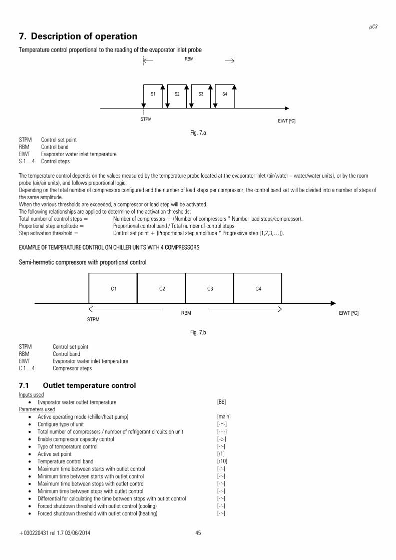
μC3
+030220431 rel 1.7 03/06/2014 45
7. Description of operation Temperature control proportional to the reading of the evaporator inlet probe
RBM
STPM EIWT [ºC]
S1 S2 S3 S4
Fig. 7.a
STPM Control set point RBM Control band EIWT Evaporator water inlet temperature S 1…4 Control steps The temperature control depends on the values measured by the temperature probe located at the evaporator inlet (air/water – water/water units), or by the room probe (air/air units), and follows proportional logic. Depending on the total number of compressors configured and the number of load steps per compressor, the control band set will be divided into a number of steps of the same amplitude. When the various thresholds are exceeded, a compressor or load step will be activated. The following relationships are applied to determine of the activation thresholds: Total number of control steps = Number of compressors + (Number of compressors * Number load steps/compressor). Proportional step amplitude = Proportional control band / Total number of control steps Step activation threshold = Control set point + (Proportional step amplitude * Progressive step [1,2,3,…]). EXAMPLE OF TEMPERATURE CONTROL ON CHILLER UNITS WITH 4 COMPRESSORS Semi-hermetic compressors with proportional control
STPM EIWT [ºC]RBM
C1 C2 C4C3
Fig. 7.b
STPM Control set point RBM Control band EIWT Evaporator water inlet temperature C 1…4 Compressor steps
7.1 Outlet temperature control Inputs used
• Evaporator water outlet temperature [B6] Parameters used
• Active operating mode (chiller/heat pump) [main]• Configure type of unit [-H-] • Total number of compressors / number of refrigerant circuits on unit [-H-] • Enable compressor capacity control [-c-] • Type of temperature control [-r-] • Active set point [r1] • Temperature control band [r10] • Maximum time between starts with outlet control [-r-] • Minimum time between starts with outlet control [-r-] • Maximum time between stops with outlet control [-r-] • Minimum time between stops with outlet control [-r-] • Differential for calculating the time between steps with outlet control [-r-] • Forced shutdown threshold with outlet control (cooling) [-r-] • Forced shutdown threshold with outlet control (heating) [-r-]
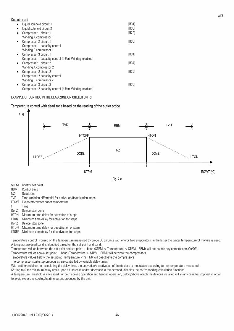
μC3
+030220431 rel 1.7 03/06/2014 46
Outputs used • Liquid solenoid circuit 1 [B31] • Liquid solenoid circuit 2 [B36] • Compressor 1 circuit 1
Winding A compressor 1 [B29]
• Compressor 2 circuit 1 Compressor 1 capacity control Winding B compressor 1
[B30]
• Compressor 3 circuit 1 Compressor 1 capacity control (if Part-Winding enabled)
[B31]
• Compressor 1 circuit 2 Winding A compressor 2
[B34]
• Compressor 2 circuit 2 Compressor 2 capacity control Winding B compressor 2
[B35]
• Compressor 3 circuit 2 Compressor 2 capacity control (if Part-Winding enabled)
[B36]
EXAMPLE OF CONTROL IN THE DEAD ZONE ON CHILLER UNITS Temperature control with dead zone based on the reading of the outlet probe
STPM
RBM
NZDOffZ DOnZ
EOWT [ºC]
TVD
t [s]
TVD
HTON
LTON
HTOFF
LTOFF
Fig. 7.c
STPM Control set point RBM Control band NZ Dead zone TVD Time variation differential for activation/deactivation steps EOWT Evaporator water outlet temperature t Time DonZ Device start zone HTON Maximum time delay for activation of steps LTON Minimum time delay for activation for steps DoffZ Device stop zone HTOFF Maximum time delay for deactivation of steps LTOFF Minimum time delay for deactivation for steps Temperature control is based on the temperature measured by probe B6 on units with one or two evaporators; in the latter the water temperature of mixture is used. A temperature dead band is identified based on the set point and band. Temperature values between the set point and set point + band (STPM < Temperature < STPM+RBM) will not switch any compressors On/Off. Temperature values above set point + band (Temperature > STPM+RBM) will activate the compressors Temperature values below the set point (Temperature < STPM) will deactivate the compressors The compressor start/stop procedures are controlled by variable delay times. With a differential set for calculating the delay time, the activation/deactivation of the devices is modulated according to the temperature measured. Setting to 0 the minimum delay times upon an increase and/or decrease in the demand, disables the corresponding calculation functions. A temperature threshold is envisaged, for both cooling operation and heating operation, below/above which the devices installed will in any case be stopped, in order to avoid excessive cooling/heating output produced by the unit.
μC3
+030220431 rel 1.7 03/06/2014 47
7.2 Differential Temperature Control Inputs used • Evaporator inlet temperature • Evaporator outlet temperature • Outside air temperature • Room temperature (acqua terminal) Parameters used • Type of unit • Total number of compressors • Number of load steps • Type of temperature control • Proportional band for inlet control or Dead zone for outlet control • Temperature difference (delta) between reference and controlled value. Outputs used • Liquid solenoid • Compressor start relay • Compressor capacity control relay Description of operation The temperature control differential is based on the difference between a reference temperature and a controlled temperature. ∆ calculated = Reference temperature – Controlled temperature The value calculated in this way is compared against the rated value. Depending on the unit operating mode, cooling or heating, the following situations may occur.
Cooling Heating ∆ calculated > rated ∆ --- Compressors On∆ calculated < rated ∆ Compressors On ---
The purpose of this function is to maintain a constant temperature difference between two components in a system, with different thermal inertia, by acting on only one of the values measured. The controlled temperature is defined as the component with the lower thermal inertia. The reference temperature is defined as the component with the higher thermal inertia.
As the unit can operate in cooling or heating mode as selected from the screen on the user interface or by the digital input, if the reference temperature equals or exceeds the controlled temperature (i.e. opposite to the unit operating mode), the operation of the controller switches from error correction to amplification; consequently, the application of this type of control is designed for systems in which the variation in controlled values occurs within certain limits dictated by the operating mode of the active unit.
Control is proportional, according to the control band set. The proportional control band is divided into a number of uniform steps, equal to the total number of compressors and load steps installed (as for inlet temperature control). The control set point is the rated temperature difference set. The value controlled is the difference calculated between the reference temperature and the controlled temperature.
To select this type of control, a special parameter is provided that indicates which signal is used by the temperature control functions: • Evaporator inlet-outlet control probe • Reference temperature– Controlled temperature
7.3 Condensing unit control Inputs used
• External control value (condensing units) [B8] • Condensing unit digital control 1 [B12] • Condensing unit digital control 2 [B13] • Condensing unit digital control 3 [B14] • Condensing unit digital control 4 [B28]
Parameters used • Configure type of unit [-H-] • Type of condensing unit control [-H-] • Select proportional or step condensing unit control [-H-]
Outputs used • Compressor 1 circuit 1. Winding A compressor 1 [B29] • Compressor 2 circuit 1. Compressor 1 capacity control.
Winding B compressor 1 [B30]
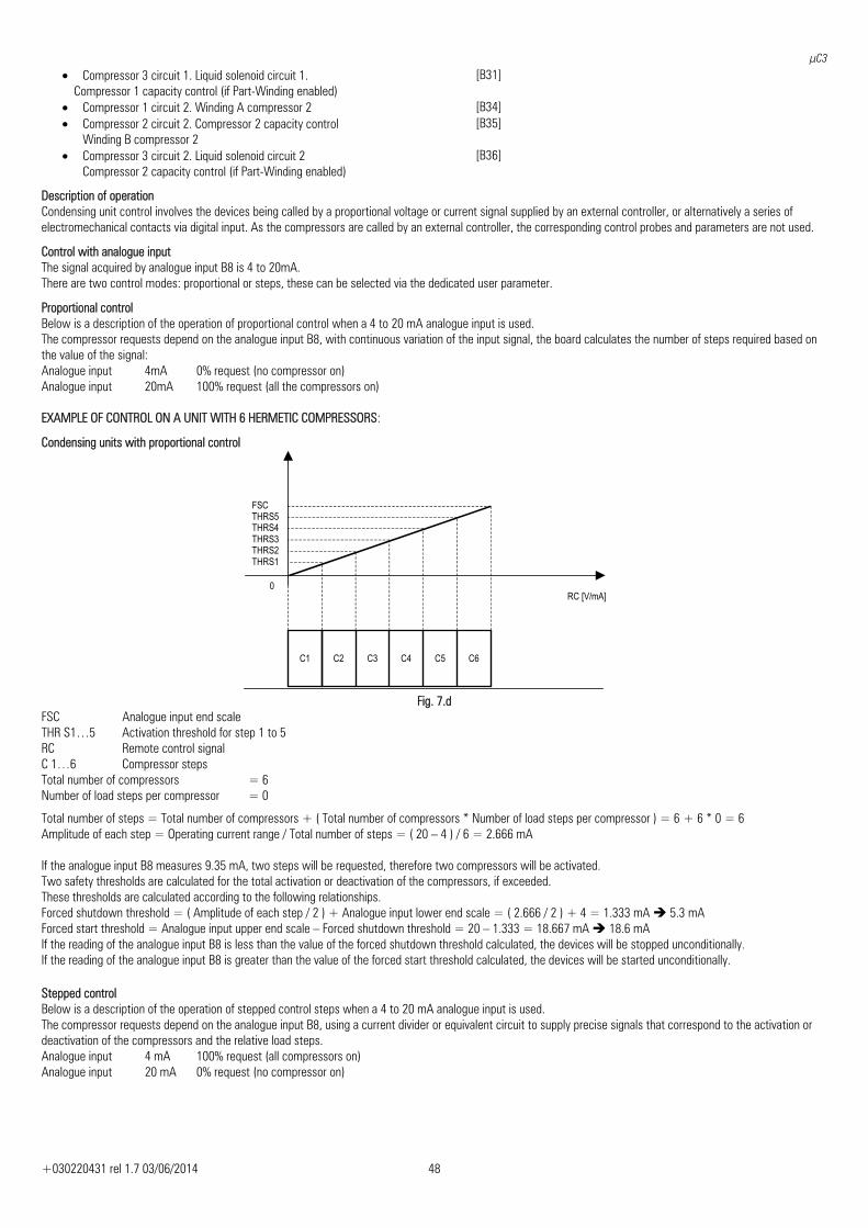
μC3
+030220431 rel 1.7 03/06/2014 48
• Compressor 3 circuit 1. Liquid solenoid circuit 1. Compressor 1 capacity control (if Part-Winding enabled)
[B31]
• Compressor 1 circuit 2. Winding A compressor 2 [B34] • Compressor 2 circuit 2. Compressor 2 capacity control
Winding B compressor 2 [B35]
• Compressor 3 circuit 2. Liquid solenoid circuit 2 Compressor 2 capacity control (if Part-Winding enabled)
[B36]
Description of operation Condensing unit control involves the devices being called by a proportional voltage or current signal supplied by an external controller, or alternatively a series of electromechanical contacts via digital input. As the compressors are called by an external controller, the corresponding control probes and parameters are not used.
Control with analogue input The signal acquired by analogue input B8 is 4 to 20mA. There are two control modes: proportional or steps, these can be selected via the dedicated user parameter.
Proportional control Below is a description of the operation of proportional control when a 4 to 20 mA analogue input is used. The compressor requests depend on the analogue input B8, with continuous variation of the input signal, the board calculates the number of steps required based on the value of the signal: Analogue input 4mA 0% request (no compressor on) Analogue input 20mA 100% request (all the compressors on) EXAMPLE OF CONTROL ON A UNIT WITH 6 HERMETIC COMPRESSORS:
Condensing units with proportional control
0
FSC
RC [V/mA]
C4C3C1 C2
THRS1 THRS2 THRS3 THRS41
THRS5
C5 C6
Fig. 7.d
FSC Analogue input end scale THR S1…5 Activation threshold for step 1 to 5 RC Remote control signal C 1…6 Compressor steps Total number of compressors = 6 Number of load steps per compressor = 0
Total number of steps = Total number of compressors + ( Total number of compressors * Number of load steps per compressor ) = 6 + 6 * 0 = 6 Amplitude of each step = Operating current range / Total number of steps = ( 20 – 4 ) / 6 = 2.666 mA If the analogue input B8 measures 9.35 mA, two steps will be requested, therefore two compressors will be activated. Two safety thresholds are calculated for the total activation or deactivation of the compressors, if exceeded. These thresholds are calculated according to the following relationships. Forced shutdown threshold = ( Amplitude of each step / 2 ) + Analogue input lower end scale = ( 2.666 / 2 ) + 4 = 1.333 mA 5.3 mA Forced start threshold = Analogue input upper end scale – Forced shutdown threshold = 20 – 1.333 = 18.667 mA 18.6 mA If the reading of the analogue input B8 is less than the value of the forced shutdown threshold calculated, the devices will be stopped unconditionally. If the reading of the analogue input B8 is greater than the value of the forced start threshold calculated, the devices will be started unconditionally.
Stepped control Below is a description of the operation of stepped control steps when a 4 to 20 mA analogue input is used. The compressor requests depend on the analogue input B8, using a current divider or equivalent circuit to supply precise signals that correspond to the activation or deactivation of the compressors and the relative load steps. Analogue input 4 mA 100% request (all compressors on) Analogue input 20 mA 0% request (no compressor on)
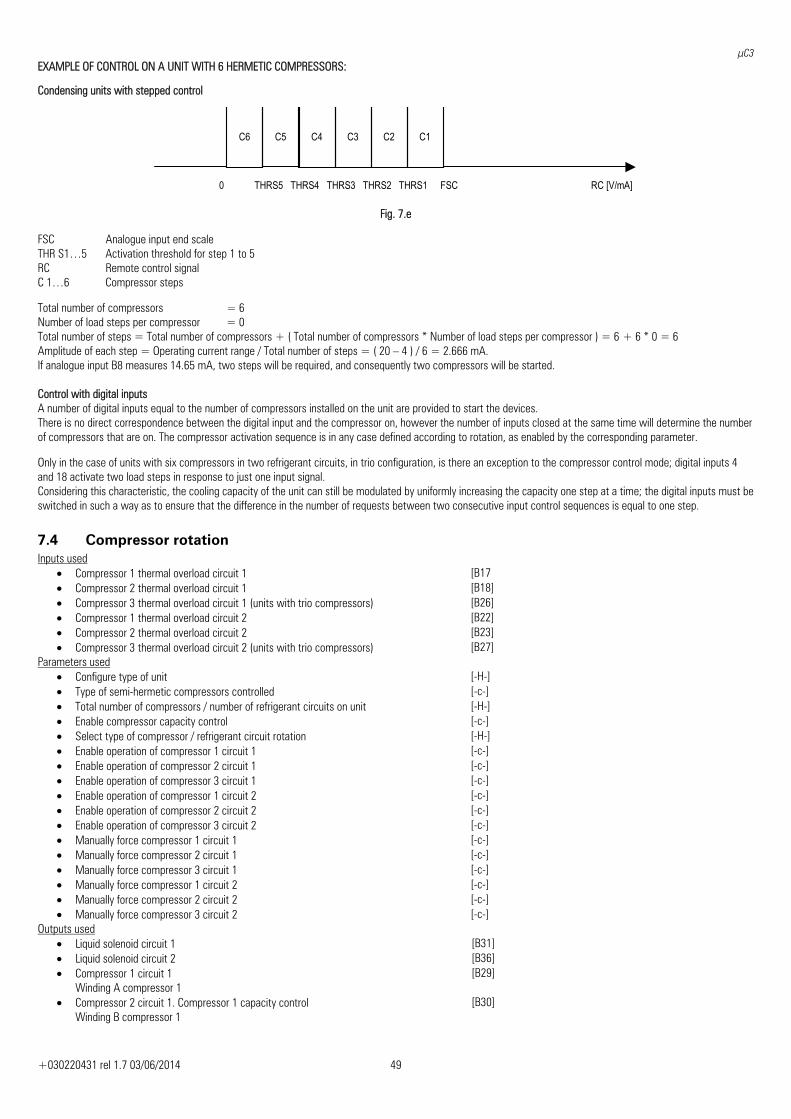
μC3
+030220431 rel 1.7 03/06/2014 49
EXAMPLE OF CONTROL ON A UNIT WITH 6 HERMETIC COMPRESSORS:
Condensing units with stepped control
RC [V/mA] FSC
C4 C3 C1C2
THRS1THRS5 THRS4 THRS3 THRS20
C5 C6
Fig. 7.e
FSC Analogue input end scale THR S1…5 Activation threshold for step 1 to 5 RC Remote control signal C 1…6 Compressor steps Total number of compressors = 6 Number of load steps per compressor = 0 Total number of steps = Total number of compressors + ( Total number of compressors * Number of load steps per compressor ) = 6 + 6 * 0 = 6 Amplitude of each step = Operating current range / Total number of steps = ( 20 – 4 ) / 6 = 2.666 mA. If analogue input B8 measures 14.65 mA, two steps will be required, and consequently two compressors will be started. Control with digital inputs A number of digital inputs equal to the number of compressors installed on the unit are provided to start the devices. There is no direct correspondence between the digital input and the compressor on, however the number of inputs closed at the same time will determine the number of compressors that are on. The compressor activation sequence is in any case defined according to rotation, as enabled by the corresponding parameter. Only in the case of units with six compressors in two refrigerant circuits, in trio configuration, is there an exception to the compressor control mode; digital inputs 4 and 18 activate two load steps in response to just one input signal. Considering this characteristic, the cooling capacity of the unit can still be modulated by uniformly increasing the capacity one step at a time; the digital inputs must be switched in such a way as to ensure that the difference in the number of requests between two consecutive input control sequences is equal to one step.
7.4 Compressor rotation Inputs used
• Compressor 1 thermal overload circuit 1 [B17 • Compressor 2 thermal overload circuit 1 [B18] • Compressor 3 thermal overload circuit 1 (units with trio compressors) [B26] • Compressor 1 thermal overload circuit 2 [B22] • Compressor 2 thermal overload circuit 2 [B23] • Compressor 3 thermal overload circuit 2 (units with trio compressors) [B27]
Parameters used • Configure type of unit [-H-] • Type of semi-hermetic compressors controlled [-c-] • Total number of compressors / number of refrigerant circuits on unit [-H-] • Enable compressor capacity control [-c-] • Select type of compressor / refrigerant circuit rotation [-H-] • Enable operation of compressor 1 circuit 1 [-c-] • Enable operation of compressor 2 circuit 1 [-c-] • Enable operation of compressor 3 circuit 1 [-c-] • Enable operation of compressor 1 circuit 2 [-c-] • Enable operation of compressor 2 circuit 2 [-c-] • Enable operation of compressor 3 circuit 2 [-c-] • Manually force compressor 1 circuit 1 [-c-] • Manually force compressor 2 circuit 1 [-c-] • Manually force compressor 3 circuit 1 [-c-] • Manually force compressor 1 circuit 2 [-c-] • Manually force compressor 2 circuit 2 [-c-] • Manually force compressor 3 circuit 2 [-c-]
Outputs used • Liquid solenoid circuit 1 [B31] • Liquid solenoid circuit 2 [B36] • Compressor 1 circuit 1
Winding A compressor 1 [B29]
• Compressor 2 circuit 1. Compressor 1 capacity control Winding B compressor 1
[B30]
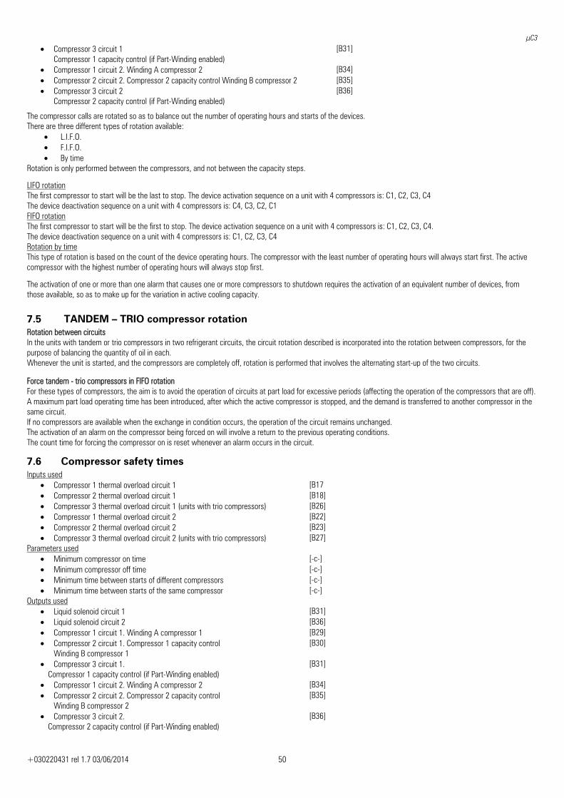
μC3
+030220431 rel 1.7 03/06/2014 50
• Compressor 3 circuit 1 Compressor 1 capacity control (if Part-Winding enabled)
[B31]
• Compressor 1 circuit 2. Winding A compressor 2 [B34] • Compressor 2 circuit 2. Compressor 2 capacity control Winding B compressor 2 [B35] • Compressor 3 circuit 2
Compressor 2 capacity control (if Part-Winding enabled) [B36]
The compressor calls are rotated so as to balance out the number of operating hours and starts of the devices. There are three different types of rotation available:
• L.I.F.O. • F.I.F.O. • By time
Rotation is only performed between the compressors, and not between the capacity steps.
LIFO rotation The first compressor to start will be the last to stop. The device activation sequence on a unit with 4 compressors is: C1, C2, C3, C4 The device deactivation sequence on a unit with 4 compressors is: C4, C3, C2, C1 FIFO rotation The first compressor to start will be the first to stop. The device activation sequence on a unit with 4 compressors is: C1, C2, C3, C4. The device deactivation sequence on a unit with 4 compressors is: C1, C2, C3, C4 Rotation by time This type of rotation is based on the count of the device operating hours. The compressor with the least number of operating hours will always start first. The active compressor with the highest number of operating hours will always stop first.
The activation of one or more than one alarm that causes one or more compressors to shutdown requires the activation of an equivalent number of devices, from those available, so as to make up for the variation in active cooling capacity.
7.5 TANDEM – TRIO compressor rotation Rotation between circuits In the units with tandem or trio compressors in two refrigerant circuits, the circuit rotation described is incorporated into the rotation between compressors, for the purpose of balancing the quantity of oil in each. Whenever the unit is started, and the compressors are completely off, rotation is performed that involves the alternating start-up of the two circuits. Force tandem - trio compressors in FIFO rotation For these types of compressors, the aim is to avoid the operation of circuits at part load for excessive periods (affecting the operation of the compressors that are off). A maximum part load operating time has been introduced, after which the active compressor is stopped, and the demand is transferred to another compressor in the same circuit. If no compressors are available when the exchange in condition occurs, the operation of the circuit remains unchanged. The activation of an alarm on the compressor being forced on will involve a return to the previous operating conditions. The count time for forcing the compressor on is reset whenever an alarm occurs in the circuit.
7.6 Compressor safety times Inputs used
• Compressor 1 thermal overload circuit 1 [B17 • Compressor 2 thermal overload circuit 1 [B18] • Compressor 3 thermal overload circuit 1 (units with trio compressors) [B26] • Compressor 1 thermal overload circuit 2 [B22] • Compressor 2 thermal overload circuit 2 [B23] • Compressor 3 thermal overload circuit 2 (units with trio compressors) [B27]
Parameters used • Minimum compressor on time [-c-] • Minimum compressor off time [-c-] • Minimum time between starts of different compressors [-c-] • Minimum time between starts of the same compressor [-c-]
Outputs used • Liquid solenoid circuit 1 [B31] • Liquid solenoid circuit 2 [B36] • Compressor 1 circuit 1. Winding A compressor 1 [B29] • Compressor 2 circuit 1. Compressor 1 capacity control
Winding B compressor 1 [B30]
• Compressor 3 circuit 1. Compressor 1 capacity control (if Part-Winding enabled)
[B31]
• Compressor 1 circuit 2. Winding A compressor 2 [B34] • Compressor 2 circuit 2. Compressor 2 capacity control
Winding B compressor 2 [B35]
• Compressor 3 circuit 2. Compressor 2 capacity control (if Part-Winding enabled)
[B36]
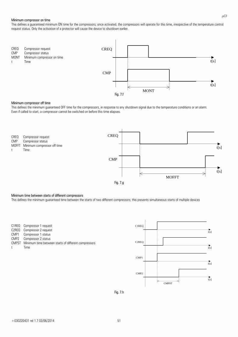
μC3
+030220431 rel 1.7 03/06/2014 51
CREQ
CMP
t[s]
t[s]
MONT
Minimum compressor on time This defines a guaranteed minimum ON time for the compressors; once activated, the compressors will operate for this time, irrespective of the temperature control request status. Only the activation of a protector will cause the device to shutdown earlier.
Fig. 7.f Minimum compressor off time This defines the minimum guaranteed OFF time for the compressors, in response to any shutdown signal due to the temperature conditions or an alarm. Even if called to start, a compressor cannot be switched on before this time elapses.
CREQ Compressor request CMP Compressor status MOFFT Minimum compressor off time t Time
Fig. 7.g Minimum time between starts of different compressors This defines the minimum guaranteed time between the starts of two different compressors; this prevents simultaneous starts of multiple devices
C1REQ Compressor 1 request C2REQ Compressor 2 request CMP1 Compressor 1 status CMP2 Compressor 2 status CMPST Minimum time between starts of different compressors t Time
Fig. 7.h
CREQ Compressor request CMP Compressor status MONT Minimum compressor on time t Time
C2REQ
CMP1
t[s]
t[s]
CMPST
CMP2
t[s]
t[s]
C1REQ
CREQ
CMP
t[s]
t[s]
MOFFT
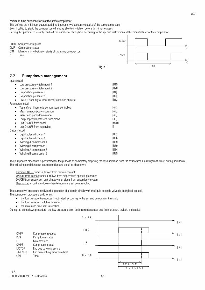
μC3
+030220431 rel 1.7 03/06/2014 52
Minimum time between starts of the same compressor This defines the minimum guaranteed time between two successive starts of the same compressor. Even if called to start, the compressor will not be able to switch on before this times elapses. Setting this parameter suitably can limit the number of starts/hour according to the specific instructions of the manufacturer of the compressor.
CREQ Compressor request CMP Compressor status CST Minimum time between starts of the same compressor t Time
Fig. 7.i
7.7 Pumpdown management Inputs used
• Low pressure switch circuit 1 [B15] • Low pressure switch circuit 2 [B20] • Evaporation pressure 1 [B1] • Evaporation pressure 2 [B2] • ON/OFF from digital input (air/air units and chillers) [B13]
Parameters used • Type of semi-hermetic compressors controlled [-c-] • Maximum pumpdown duration [-c-] • Select end pumpdown mode [-c-] • End pumpdown pressure from probe [-c-] • Unit ON/OFF from panel [main]• Unit ON/OFF from supervisor []
Outputs used • Liquid solenoid circuit 1 [B31] • Liquid solenoid circuit 2 [B36] • Winding A compressor 1 [B29] • Winding B compressor 1 [B30] • Winding A compressor 2 [B34] • Winding B compressor 2 [B35]
The pumpdown procedure is performed for the purpose of completely emptying the residual freon from the evaporator in a refrigerant circuit during shutdown. The following conditions can cause a refrigerant circuit to shutdown:
Remote ON/OFF: unit shutdown from remote contact ON/OFF from keypad: unit shutdown from display with specific procedure ON/OFF from supervisor: unit shutdown on signal from supervisory system Thermostat: circuit shutdown when temperature set point reached
The pumpdown procedure involves the operation of a certain circuit with the liquid solenoid valve de-energised (closed). The pumpdown procedure ends when:
• the low pressure transducer is activated, according to the set end pumpdown threshold • the low pressure switch is activated • the maximum time limit is reached
During the pumpdown procedure, the low pressure alarm, both from transducer and from pressure switch, is disabled.
Fig.7.l
CMPR Compressor request PDS Pumpdown status LP Low pressure CMPS Compressor status LPSTOP End due to low pressure TIMESTOP End on reaching maximum time t [s] Time
CREQ
CMP
t[s]
t[s]
CST
μC3
+030220431 rel 1.7 03/06/2014 53
7.8 Main pump management Inputs used
• Evaporator water flow switch [B12] • Evaporator pump 1 thermal overload [B14] • Evaporator pump 2 thermal overload [B28]
Parameters used • Number of evaporator pumps [-H-] • Evaporator pump/main fan operating mode [-H-] • Delay between start of pump/main fan and compressors [-c-] • Delay for stopping the pump/main fan [-c-] • ON time in burst operation [-H-] • OFF time in burst operation [-H-]
Outputs used • Evaporator pump 1 [B33] • Evaporator pump 2 [B36]
The main circulating pump can be managed in four different operating modes:
• Always on: the pump is activated when the unit is started and remains active while the unit is operating; if there are two pumps, the devices will be rotated according to the specific settings
• On according to the status of the compressor: the pump is on according to the compressor call status; consequently, when the set point has been reached, the circulating pump and compressors, excepting in the case of safety times, are off
• Burst operation: normally the circulating pump is off, and is activated periodically for a set time; the unit temperature conditions are constantly monitored and the compressors are started if necessary; when the control set point is reached the pump is switched off
• Always off: the main circulating pump is not managed, whatever the operating conditions of the unit Two safety times are observed, respectively a compressor activation delay after the circulating pump starts, and pump shutdown delay after the compressors stop when having reached the control set point or the unit is shutdown.
7.9 Pump rotation Inputs used
• Evaporator water flow switch [B12] • Evaporator pump 1 thermal overload [B14] • Evaporator pump 2 thermal overload [B28]
Parameters used • Number of evaporator pumps [-H-] • Select type of evaporator pump rotation [-H-] • Operating hour threshold for the rotation of the evaporator pumps [-H-]
Outputs used • Evaporator pump 1 [B33] • Evaporator pump 2 [B36]
If there are two circulating pumps on the unit, the operation of these can be rotated in the following modes:
• Rotation at start: when the unit is started, the operation of the pumps is rotated, so as to balance the number of starts-stops of the devices • Rotation by time: a rotation time is established (expressed in hours), which when reached the devices are rotated, so as to balance the number of
operating hours of the devices.
Control of the second circulating pump in any case involves forced rotation in the event of an alarm event of one of the devices, to ensure maximum continuity of operation. Pump thermal overload alarm If a thermal overload alarm is activated on the active circulating pump, the pump is stopped and the devices are rotated. A further activation of the thermal overload alarm on the active reserve pump causes the total shutdown of the unit due to no other pump being available on power-up, and a new rotation is forced. Evaporator flow switch alarm The activation of the evaporator flow switch alarm forces the rotation of the devices and the activation of the reserve pump; in this condition, the alarm signal delay time in steady operation is re-activated, after which, with the alarm active, the unit is switched off. Evaporator flow switch alarm/intervention The evaporator flow switch intervention generates the EVAPORATOR FLOW SWITCH ALARM respecting the following time:
• Evaporator flow switch alarm delay at start-up • Evaporator flow switch alarm delay in steady operation
If there are 2 evaporator pumps, the intervention of the flow switch causes the startup of the backup pump. If after the " Evaporator flow switch alarm delay at start-up” the flow switch signal is still present, the EVAPORATOR FLOW SWITCH ALARM occurs and the unit is turned off. The compressors , after the startup of the backup pump, remain still ON for a delay time in steady operation.
μC3
+030220431 rel 1.7 03/06/2014 54
7.10 Electric heaters Inputs used
• Room temperature (air/air units) Evaporator water inlet temperature [B5] • Air outlet temperature (air/air units) Evaporator water outlet temperature [B6] • Evaporator 1 water outlet temperature [B9] • Evaporator 2 water outlet temperature [B10] • Outside air temperature [B7] • Boiler temperature [B1]
Parameters used • Select number of evaporators [-H-] • Type of temperature control [-r-] • Enable analogue probe 7 Outside air temperature [-/-] • Enable analogue probe 1 Boiler temperature [-/-] • Configuration of analogue inputs 1 and 2 [-/-] • Antifreeze heater set point [A3] • Antifreeze heater differential [A4] • Support heater set point in cooling mode [A5] • Support heater differential in cooling mode [A6] • Support heater set point 1 in heating mode [A7] • Support heater differential 1 in heating mode [A8] • Support heater set point 2 in heating mode [A9] • Support heater differential 1 in heating mode [A10] • Delay in activation of the support heater in heating mode [A11] • Select probe for cooling support control in air/air units [-A-] • Outside air set point to enable support heater [-A-] • Outside air differential to enable support heater [-A-] • Boiler temperature set point to enable support heater [-A-] • Boiler temperature differential to enable support heater [-A-] • Active operating mode (chiller/heat pump) [main]
Outputs used • Status of digital output 11. Heater 1 [B39] • Status of digital output 12. Heater 2 [B40]
Antifreeze heater To prevent the activation of the antifreeze protection one or more electric heaters are used, immersed in the flow of water at the evaporator and controlled based on by a set point and differential. The activation of the antifreeze heater causes the total shutdown of the compressors, or in any case disables the cooling devices, until the temperature returns above the heater set point + differential.
Support heater in cooling To prevent the activation of the minimum room temperature limit protection in air/air units, an electric heater is activated, immersed in the main air flow, controlled based on a set point and differential. The activation of the support heater in cooling causes the total shutdown of the compressors, or in any case disables the cooling devices, until the temperature returns above the heater set point + differential. SUPPORT HEATERS IN HEATING
Heating support function on water/air – water/water units In units operating in heating mode with reversal on the refrigerant circuit, electric heaters (used in cooling mode as evaporator antifreeze heaters) are used to support the heating function, if the operation of the unit cannot satisfy the thermal load of the installation. These heaters are controlled based on the unit temperature control probe (inlet or outlet, according to the setting made), while two separate set points and differentials are set for the activation of the devices. In the event of control based on the temperature measured at the evaporator outlet, in units with one and two evaporators, the heaters will be controlled based on the values measured by analogue input B6.
Heating support function on air/air units In units operating in heating mode with reversal on the refrigerant circuit, electric heaters are used to support the heating function, if the operation of the unit cannot satisfy the thermal load of the installation. The user can set whether the heater is activated based on the room temperature or the outlet temperature. The support heaters are managed by setting an activation delay time, calculated from when the circulating pump starts, so as to give the unit time to reach steady operation. Enabling the control set point compensation function will also cause the compensation of the heater set point, according to the same temperature difference calculated.
Boiler function If the reading of analogue input B1 is enabled and configured as the boiler temperature, the operation of the heaters can be managed based on the outside temperature conditions and the water temperature in the storage cylinder. Once having set a control set point and differential for both readings, the support heaters will be activated based on the control temperature measured (inlet or outlet, according to the specific setting) in reference to specific set points and differentials, only if the outside temperature conditions and boiler conditions allow.
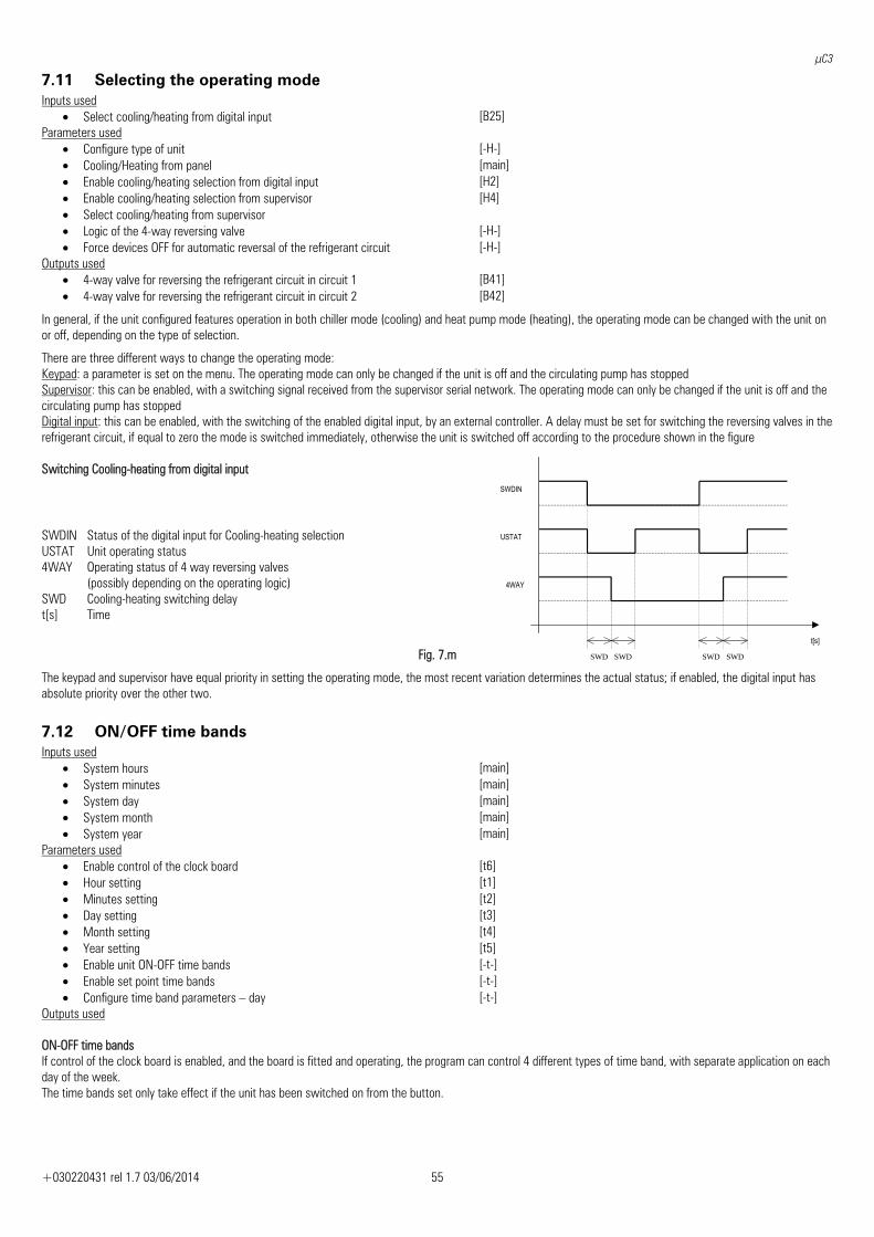
μC3
+030220431 rel 1.7 03/06/2014 55
7.11 Selecting the operating mode Inputs used
• Select cooling/heating from digital input [B25] Parameters used
• Configure type of unit [-H-] • Cooling/Heating from panel [main]• Enable cooling/heating selection from digital input [H2] • Enable cooling/heating selection from supervisor [H4] • Select cooling/heating from supervisor • Logic of the 4-way reversing valve [-H-] • Force devices OFF for automatic reversal of the refrigerant circuit [-H-]
Outputs used • 4-way valve for reversing the refrigerant circuit in circuit 1 [B41] • 4-way valve for reversing the refrigerant circuit in circuit 2 [B42]
In general, if the unit configured features operation in both chiller mode (cooling) and heat pump mode (heating), the operating mode can be changed with the unit on or off, depending on the type of selection.
There are three different ways to change the operating mode: Keypad: a parameter is set on the menu. The operating mode can only be changed if the unit is off and the circulating pump has stopped Supervisor: this can be enabled, with a switching signal received from the supervisor serial network. The operating mode can only be changed if the unit is off and the circulating pump has stopped Digital input: this can be enabled, with the switching of the enabled digital input, by an external controller. A delay must be set for switching the reversing valves in the refrigerant circuit, if equal to zero the mode is switched immediately, otherwise the unit is switched off according to the procedure shown in the figure Switching Cooling-heating from digital input
SWDIN Status of the digital input for Cooling-heating selection USTAT Unit operating status 4WAY Operating status of 4 way reversing valves
(possibly depending on the operating logic) SWD Cooling-heating switching delay t[s] Time
Fig. 7.m
The keypad and supervisor have equal priority in setting the operating mode, the most recent variation determines the actual status; if enabled, the digital input has absolute priority over the other two.
7.12 ON/OFF time bands Inputs used
• System hours [main]• System minutes [main]• System day [main]• System month [main]• System year [main]
Parameters used • Enable control of the clock board [t6] • Hour setting [t1] • Minutes setting [t2] • Day setting [t3] • Month setting [t4] • Year setting [t5] • Enable unit ON-OFF time bands [-t-] • Enable set point time bands [-t-] • Configure time band parameters – day [-t-]
Outputs used ON-OFF time bands If control of the clock board is enabled, and the board is fitted and operating, the program can control 4 different types of time band, with separate application on each day of the week. The time bands set only take effect if the unit has been switched on from the button.
t[s]
SWDIN
USTAT
4WAY
SWD SWD SWD SWD
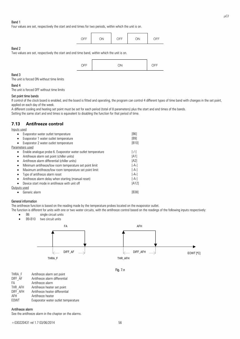
μC3
+030220431 rel 1.7 03/06/2014 56
Band 1 Four values are set, respectively the start and end times for two periods, within which the unit is on.
Band 2 Two values are set, respectively the start and end time band, within which the unit is on.
Band 3 The unit is forced ON without time limits
Band 4 The unit is forced OFF without time limits
Set point time bands If control of the clock board is enabled, and the board is fitted and operating, the program can control 4 different types of time band with changes in the set point, applied on each day of the week. A different cooling and heating set point must be set for each period (total of 8 parameters) plus the start and end times of the bands. Setting the same start and end times is equivalent to disabling the function for that period of time.
7.13 Antifreeze control Inputs used
• Evaporator water outlet temperature [B6] • Evaporator 1 water outlet temperature [B9] • Evaporator 2 water outlet temperature [B10]
Parameters used • Enable analogue probe 6. Evaporator water outlet temperature [-/-] • Antifreeze alarm set point (chiller units) [A1] • Antifreeze alarm differential (chiller units) [A2] • Minimum antifreeze/low room temperature set point limit [-A-] • Maximum antifreeze/low room temperature set point limit [-A-] • Type of antifreeze alarm reset [-A-] • Antifreeze alarm delay when starting (manual reset) [-A-] • Device start mode in antifreeze with unit off [A12]
Outputs used • Generic alarm [B38]
General information The antifreeze function is based on the reading made by the temperature probes located on the evaporator outlet. The function is different for units with one or two water circuits, with the antifreeze control based on the readings of the following inputs respectively:
• B6 single circuit units • B9-B10 two circuit units
THRA_F
DIFF_AF
THR_AFH
DIFF_AFH
FA AFH
EOWT [ºC]
Fig. 7.n
THRA_F Antifreeze alarm set point DIFF_AF Antifreeze alarm differential FA Antifreeze alarm THR_AFH Antifreeze heater set point DIFF_AFH Antifreeze heater differential AFH Antifreeze heater EOWT Evaporator water outlet temperature Antifreeze alarm See the antifreeze alarm in the chapter on the alarms.
μC3
+030220431 rel 1.7 03/06/2014 57
7.14 Condenser - evaporator control Inputs used
• Condensing temperature 1 [B1] • Condensing temperature 2 [B2] • Outside air temperature [B7] • Condensing pressure 1 [B3] • Condensing pressure 2 [B4]
Parameters used • Type of condenser control [-F-] • Number of condensers installed [-F-] • Type of condensing devices controlled [-F-] • Total number of fans installed [-F-] • Forcing time when starting the condenser (control by temperature) [-F-] • Maximum voltage threshold for Triac [-F-] • Minimum voltage threshold for Triac [-F-] • Amplitude impulse for phase control [-F-] • Condenser control set point (cooling) [-F-] • Condenser differential (cooling) [-F-] • Evaporator set point (heating) [-F-] • Evaporator differential (heating) [-F-] • Fan operation differential at minimum speed [-F-] • Maximum fan speed with inverter [-F-] • Minimum fan speed with inverter [-F-] • Speed-up time with inverter [-F-] • Enable high pressure prevent [-F-] [-F-] [-F-] • High pressure prevent set point(cooling) [-F-] • High pressure prevent differential(cooling) [-F-] • Low pressure prevent set point(heating) [-F-] • Low pressure prevent differential(heating) [-F-] • Condenser operating mode in the event of probe fault [-F-] • End prevent delay [-F-] • Start hour for low-noise operation [F1] • Start minutes for low-noise operation [F2] • End hour for low-noise operation [F3] • End minutes for low-noise operation [F4] • Low-noise set point in cooling [F5] • Low-noise set point in heating [F6] • Enable control of the clock board [t6] • Active operating mode (chiller/heat pump) [main]
Outputs used • Fan 1 circuit 1 [B32] • Fan 2 circuit 1 [B31] • Fan 2 circuit 1 (1 condenser) [B37] • Fan 1 circuit 2 (2 condensers) [B37] • Fan 2 circuit 2 [B36] • Status of analogue output 1
Condenser fans circuit 1 [B43]
• Status of analogue output 2 Condenser fans circuit 2
[B44]
Condenser-evaporator on/off linked to compressor operation The operation of the fans will be slaved exclusively to the operation of the compressors: Compressor off = fan off Compressor on = fan on No pressure or temperature transducers need to be installed
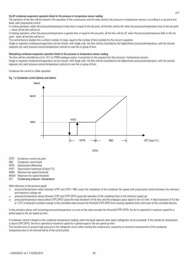
μC3
+030220431 rel 1.7 03/06/2014 58
On/off condenser-evaporator operation linked to the pressure or temperature sensor reading The operation of the fans will be slaved to the operation of the compressors and the value read by the pressure or temperature sensors, according to a set point and band, with proportional control. In cooling operation, when the pressure/temperature is less than or equal to the set point, all the fans will be off; when the pressure/temperature rises to the set point + band, all the fans will be on. In heating operation, when the pressure/temperature is greater than or equal to the set point, all the fans will be off; when the pressure/temperature falls to the set point - band, all the fans will be on. The control band is divided into a uniform number of steps, equal to the number of fans installed for the circuit in question. Single or separate condensers/evaporators can be chosen; with single coils, the fans will be controlled by the higher/lower pressure/temperature, with the second separate coil, each pressure sensor/temperature controls its own fan or group of fans. Modulating condenser-evaporator operation linked to the pressure or temperature sensor reading The fans will be controlled by a 0 to 10 V or PWM analogue output, in proportion to the request from the pressure / temperature sensors. Single or separate condensers/evaporators can be chosen; with single coils, the fans will be controlled by the higher/lower pressure/temperature, with the second separate coil, each pressure sensor/temperature controls its own fan or group of fans. Condenser fan control in chiller operation Fig. 7.o Condenser control devices and alarms
STPC Condenser control set point RBC Condenser control band OFFD Deactivation differential HYST Deactivation hysteresis (0.5bar/1°C) MINV Minimum fan speed threshold MAXV Maximum fan speed threshold CPT Condensing pressure / temperature With reference to the previous graph: o pressure/temperature values between STPC and STPC+RBC cause the modulation of the condenser fan speed with proportional control between the minimum
and maximum voltage set o pressure/temperature values between STPC and STPC-OFFD cause the operation of the condenser fans at the minimum speed set o pressure/temperature values below STPC-OFFD cause the total shutdown of the fans and the analogue output signal is set to 0 Volt. A fixed hysteresis of 0.5 bar
or 1.0°C is featured to prevent swings in the controlled value around the threshold STPC-OFFD from causing repeated starts and stops of the controlled devices. In the activation phase with increasing pressure/temperature, as soon as the value exceeds the threshold STPC-OFFD, the fan is operated at maximum speed for a period equal to the set speed-up time. If condenser control is based on the condenser temperature reading, when the liquid solenoid valve opens (refrigerant circuit activated), if the outside air temperature is above STPC-OFFD, the fan is operated at maximum speed for a period equal to the set speed-up time. This function aims to prevent high pressure in the refrigerant circuit when starting the compressors, caused by an incorrect measurement of the condenser temperature due to the thermal inertia of the control probe.
Speed
CPT [bar/°C]
STPC
RBCOFFD
MAXV
MINV HYST
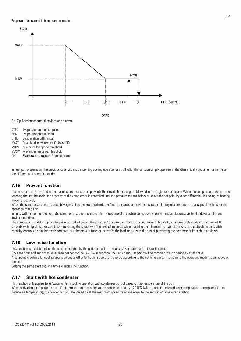
μC3
+030220431 rel 1.7 03/06/2014 59
Evaporator fan control in heat pump operation
Fig. 7.p Condenser control devices and alarms STPC Evaporator control set point RBC Evaporator control band OFFD Deactivation differential HYST Deactivation hysteresis (0.5bar/1°C) MINV Minimum fan speed threshold MAXV Maximum fan speed threshold CPT Evaporation pressure / temperature In heat pump operation, the previous observations concerning cooling operation are still valid; the function simply operates in the diametrically opposite manner, given the different unit operating mode.
7.15 Prevent function This function can be enabled in the manufacturer branch, and prevents the circuits from being shutdown due to a high pressure alarm. When the compressors are on, once reaching the set threshold, the capacity of the compressor is controlled until the pressure returns below or above the set point by a set differential, in cooling or heating mode respectively. When the compressors are off, once having reached the set threshold, the fans are started at maximum speed until the pressure returns to acceptable values for the operation of the unit. In units with tandem or trio hermetic compressors, the prevent function stops one of the active compressors, performing a rotation so as to shutdown a different device each time. The compressor shutdown procedure is repeated whenever the pressure/temperature exceeds the set prevent threshold, or alternatively waits a fixed time of 10 seconds with high/low pressure before repeating the shutdown. The procedure stops when reaching the minimum number of devices on per circuit. In units with capacity-controlled semi-hermetic compressors, the prevent function activates the load steps, with the aim of preventing the compressor from shutting down.
7.16 Low noise function This function is used to reduce the noise generated by the unit, due to the condenser/evaporator fans, at specific times. Once the start and end times have been defined for the Low Noise function, the unit control set point will be modified in such period by a set value. A set point is defined for cooling operation and another for heating operation, applied according to the set time band, in relation to the operating mode that is active on the unit. Setting the same start and end times disables the function.
7.17 Start with hot condenser This function only applies to air/water units in cooling operation with condenser control based on the temperature of the coil. When activating a refrigerant circuit, if the temperature measured at the condenser is above 20.0°C (when starting, the condenser temperature corresponds to the outside air temperature), the condenser fans are forced on at the maximum speed for a time equal to the set forcing time when starting.
Speed
EPT [bar/°C]
STPE
RBC OFFD
MAXV
MINV HYST
μC3
+030220431 rel 1.7 03/06/2014 60
7.18 Defrost control in air/water – Air/air units Inputs used
• Condensing temperature 1 [B1] • Condensing temperature 2 [B2] • Outside air temperature [B7] • Condensing pressure 1 [B3] • Condensing pressure 2 [B4]
Parameters used • Select values for start and end defrost control [-d-] • Type of defrost between circuits [-d-] • Select end defrost mode [-d-] • Start defrost threshold [d1] • End defrost threshold [d2] • Defrost activation delay [-d-] • Maximum defrost duration [-d-] • Minimum defrost duration [-d-] • Delay between defrosts on same circuit [-d-] • Delay between defrosts on different circuits [-d-] • Forced compressor off time at start and end defrost [-d-] • Delay in reversing refrigerant circuit for defrost [-d-] • Enable sliding defrost function [d3] • Minimum start defrost set point allowed with sliding defrost function [d4] • Outside temperature threshold to start sliding defrost action [d5] • Outside temperature threshold for maximum sliding defrost action [d6] • Enable manual defrost actuator [-d-] • Manual defrost on circuit 1 [-d-] • Manual defrost on circuit 2 [-d-]
Outputs used • Compressor 1 circuit 1
Winding A compressor 1 [B29]
• Compressor 2 circuit 1 Winding B compressor 1
[B30]
• Compressor 3 circuit 1 [B31] • Compressor 1 circuit 2
Winding A compressor 2 [B34]
• Compressor 2 circuit 2 Winding B compressor 2
[B35]
• Compressor 3 circuit 2 [B36] • 4-way reversing valve circuit 1 [B41] • 4-way reversing valve circuit 2 [B42] • Fan 1 circuit 1 [B32] • Fan 2 circuit 1 [B31] • Fan 2 circuit 1 (single condenser) [B37] • Fan 1 circuit 2 (2 condensers) [B37] • Fan 2 circuit 2 [B36] • Analogue output 1 status
Condenser fans circuit 1 [B43]
• Analogue output 2 status Condenser fans circuit 2
[B44]
7.19 Types of defrost Simultaneous Only one circuit needs a defrost request (temperature/pressure below the start defrost threshold) for all the circuits to be forced to defrost. The circuits which do not require defrosting (temperature/pressure above the end defrost threshold) stop and go to standby; as soon as all the circuits end their defrost cycle the compressors can start again in heat pump operation. Separate The circuits are defrosted separately by the circuits. The first circuit that requires defrosting starts the procedure, while the others wait for the end defrost (heat pump operation) before reversing the cycle and sequentially performing the defrost.
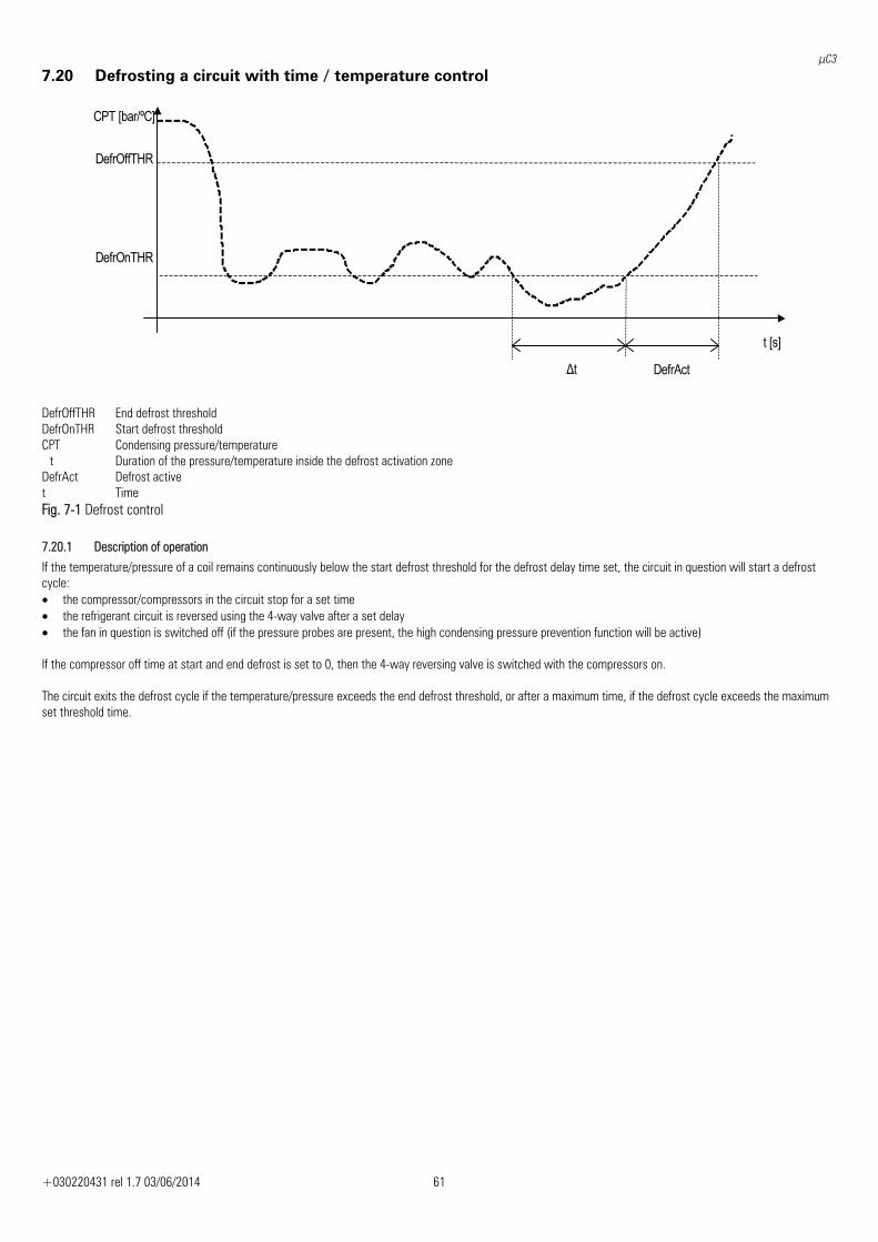
μC3
+030220431 rel 1.7 03/06/2014 61
7.20 Defrosting a circuit with time / temperature control
t [s]
Δt DefrAct
CPT [bar/ºC]
DefrOnTHR
DefrOffTHR
DefrOffTHR End defrost threshold DefrOnTHR Start defrost threshold CPT Condensing pressure/temperature t Duration of the pressure/temperature inside the defrost activation zone DefrAct Defrost active t Time Fig. 7-1 Defrost control
7.20.1 Description of operation
If the temperature/pressure of a coil remains continuously below the start defrost threshold for the defrost delay time set, the circuit in question will start a defrost cycle: • the compressor/compressors in the circuit stop for a set time • the refrigerant circuit is reversed using the 4-way valve after a set delay • the fan in question is switched off (if the pressure probes are present, the high condensing pressure prevention function will be active) If the compressor off time at start and end defrost is set to 0, then the 4-way reversing valve is switched with the compressors on. The circuit exits the defrost cycle if the temperature/pressure exceeds the end defrost threshold, or after a maximum time, if the defrost cycle exceeds the maximum set threshold time.
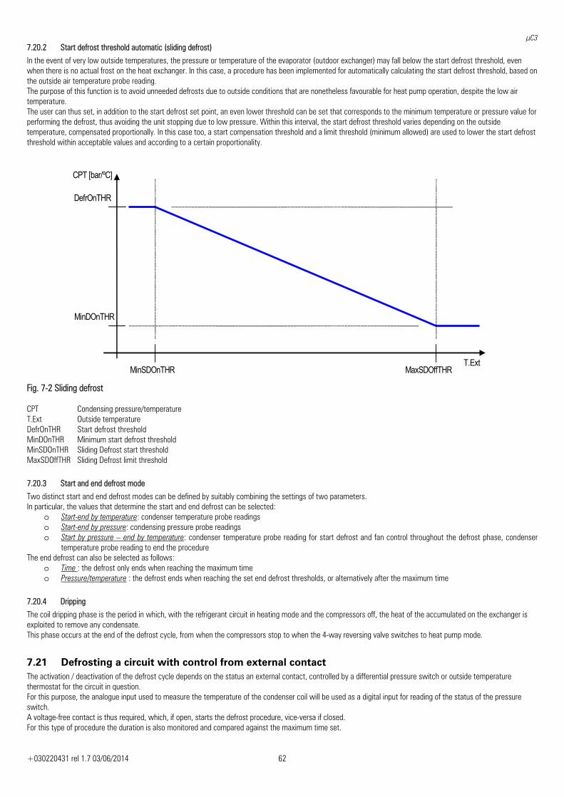
μC3
+030220431 rel 1.7 03/06/2014 62
7.20.2 Start defrost threshold automatic (sliding defrost)
In the event of very low outside temperatures, the pressure or temperature of the evaporator (outdoor exchanger) may fall below the start defrost threshold, even when there is no actual frost on the heat exchanger. In this case, a procedure has been implemented for automatically calculating the start defrost threshold, based on the outside air temperature probe reading. The purpose of this function is to avoid unneeded defrosts due to outside conditions that are nonetheless favourable for heat pump operation, despite the low air temperature. The user can thus set, in addition to the start defrost set point, an even lower threshold can be set that corresponds to the minimum temperature or pressure value for performing the defrost, thus avoiding the unit stopping due to low pressure. Within this interval, the start defrost threshold varies depending on the outside temperature, compensated proportionally. In this case too, a start compensation threshold and a limit threshold (minimum allowed) are used to lower the start defrost threshold within acceptable values and according to a certain proportionality.
DefrOnTHR
MinDOnTHR
CPT [bar/ºC]
T.Ext MinSDOnTHR MaxSDOffTHR
Fig. 7-2 Sliding defrost
CPT Condensing pressure/temperature T.Ext Outside temperature DefrOnTHR Start defrost threshold MinDOnTHR Minimum start defrost threshold MinSDOnTHR Sliding Defrost start threshold MaxSDOffTHR Sliding Defrost limit threshold
7.20.3 Start and end defrost mode
Two distinct start and end defrost modes can be defined by suitably combining the settings of two parameters. In particular, the values that determine the start and end defrost can be selected:
o Start-end by temperature: condenser temperature probe readings o Start-end by pressure: condensing pressure probe readings o Start by pressure – end by temperature: condenser temperature probe reading for start defrost and fan control throughout the defrost phase, condenser
temperature probe reading to end the procedure The end defrost can also be selected as follows:
o Time : the defrost only ends when reaching the maximum time o Pressure/temperature : the defrost ends when reaching the set end defrost thresholds, or alternatively after the maximum time
7.20.4 Dripping
The coil dripping phase is the period in which, with the refrigerant circuit in heating mode and the compressors off, the heat of the accumulated on the exchanger is exploited to remove any condensate. This phase occurs at the end of the defrost cycle, from when the compressors stop to when the 4-way reversing valve switches to heat pump mode.
7.21 Defrosting a circuit with control from external contact The activation / deactivation of the defrost cycle depends on the status an external contact, controlled by a differential pressure switch or outside temperature thermostat for the circuit in question. For this purpose, the analogue input used to measure the temperature of the condenser coil will be used as a digital input for reading of the status of the pressure switch. A voltage-free contact is thus required, which, if open, starts the defrost procedure, vice-versa if closed. For this type of procedure the duration is also monitored and compared against the maximum time set.
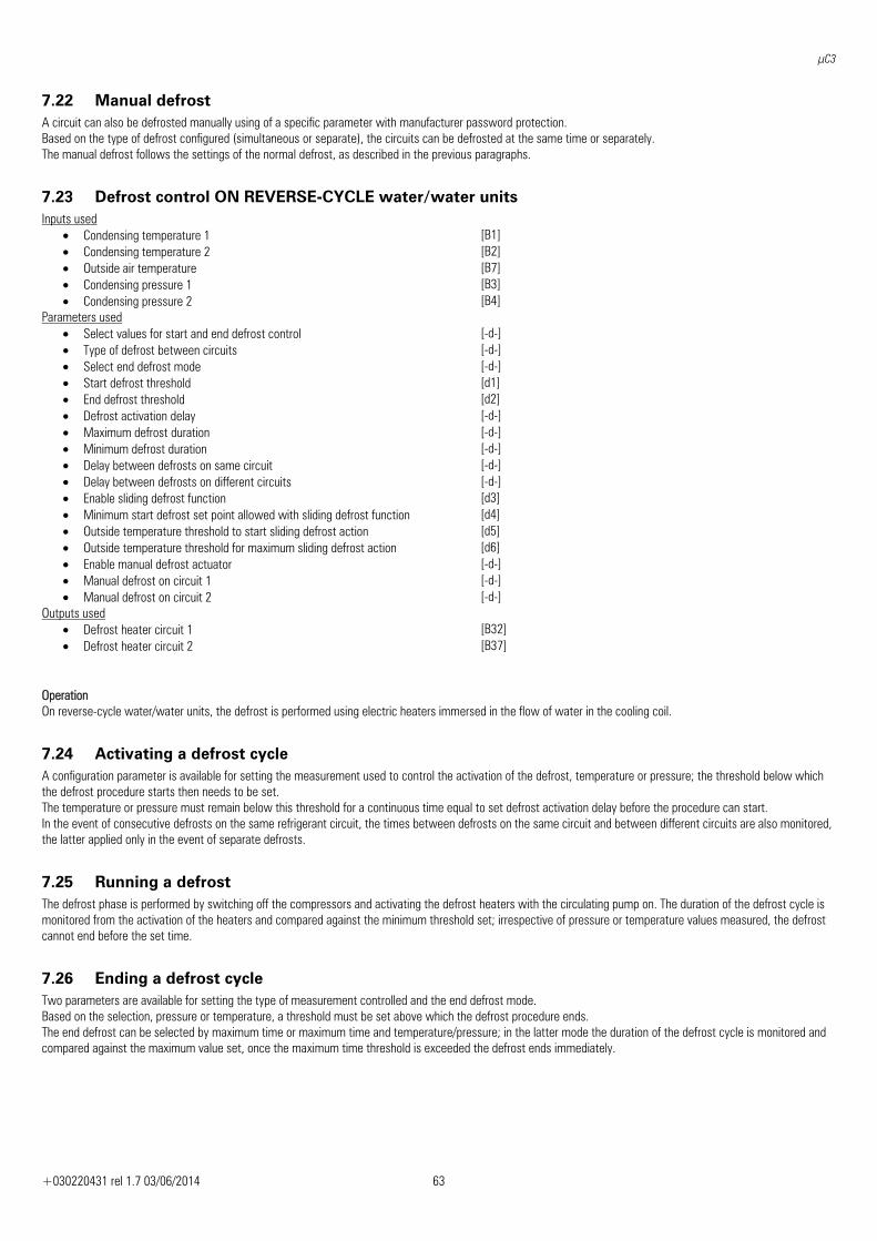
μC3
+030220431 rel 1.7 03/06/2014 63
7.22 Manual defrost A circuit can also be defrosted manually using of a specific parameter with manufacturer password protection. Based on the type of defrost configured (simultaneous or separate), the circuits can be defrosted at the same time or separately. The manual defrost follows the settings of the normal defrost, as described in the previous paragraphs.
7.23 Defrost control ON REVERSE-CYCLE water/water units Inputs used
• Condensing temperature 1 [B1] • Condensing temperature 2 [B2] • Outside air temperature [B7] • Condensing pressure 1 [B3] • Condensing pressure 2 [B4]
Parameters used • Select values for start and end defrost control [-d-] • Type of defrost between circuits [-d-] • Select end defrost mode [-d-] • Start defrost threshold [d1] • End defrost threshold [d2] • Defrost activation delay [-d-] • Maximum defrost duration [-d-] • Minimum defrost duration [-d-] • Delay between defrosts on same circuit [-d-] • Delay between defrosts on different circuits [-d-] • Enable sliding defrost function [d3] • Minimum start defrost set point allowed with sliding defrost function [d4] • Outside temperature threshold to start sliding defrost action [d5] • Outside temperature threshold for maximum sliding defrost action [d6] • Enable manual defrost actuator [-d-] • Manual defrost on circuit 1 [-d-] • Manual defrost on circuit 2 [-d-]
Outputs used • Defrost heater circuit 1 [B32] • Defrost heater circuit 2 [B37]
Operation On reverse-cycle water/water units, the defrost is performed using electric heaters immersed in the flow of water in the cooling coil.
7.24 Activating a defrost cycle A configuration parameter is available for setting the measurement used to control the activation of the defrost, temperature or pressure; the threshold below which the defrost procedure starts then needs to be set. The temperature or pressure must remain below this threshold for a continuous time equal to set defrost activation delay before the procedure can start. In the event of consecutive defrosts on the same refrigerant circuit, the times between defrosts on the same circuit and between different circuits are also monitored, the latter applied only in the event of separate defrosts.
7.25 Running a defrost The defrost phase is performed by switching off the compressors and activating the defrost heaters with the circulating pump on. The duration of the defrost cycle is monitored from the activation of the heaters and compared against the minimum threshold set; irrespective of pressure or temperature values measured, the defrost cannot end before the set time.
7.26 Ending a defrost cycle Two parameters are available for setting the type of measurement controlled and the end defrost mode. Based on the selection, pressure or temperature, a threshold must be set above which the defrost procedure ends. The end defrost can be selected by maximum time or maximum time and temperature/pressure; in the latter mode the duration of the defrost cycle is monitored and compared against the maximum value set, once the maximum time threshold is exceeded the defrost ends immediately.
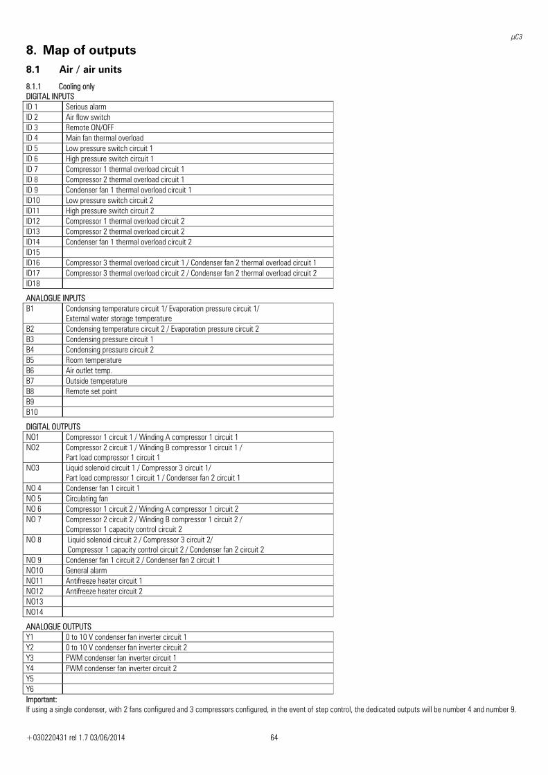
μC3
+030220431 rel 1.7 03/06/2014 64
8. Map of outputs 8.1 Air / air units
8.1.1 Cooling only DIGITAL INPUTS ID 1 Serious alarm ID 2 Air flow switch ID 3 Remote ON/OFF ID 4 Main fan thermal overload ID 5 Low pressure switch circuit 1 ID 6 High pressure switch circuit 1 ID 7 Compressor 1 thermal overload circuit 1 ID 8 Compressor 2 thermal overload circuit 1 ID 9 Condenser fan 1 thermal overload circuit 1 ID10 Low pressure switch circuit 2 ID11 High pressure switch circuit 2 ID12 Compressor 1 thermal overload circuit 2 ID13 Compressor 2 thermal overload circuit 2 ID14 Condenser fan 1 thermal overload circuit 2 ID15 ID16 Compressor 3 thermal overload circuit 1 / Condenser fan 2 thermal overload circuit 1 ID17 Compressor 3 thermal overload circuit 2 / Condenser fan 2 thermal overload circuit 2 ID18
ANALOGUE INPUTS B1 Condensing temperature circuit 1/ Evaporation pressure circuit 1/
External water storage temperature B2 Condensing temperature circuit 2 / Evaporation pressure circuit 2 B3 Condensing pressure circuit 1 B4 Condensing pressure circuit 2 B5 Room temperature B6 Air outlet temp. B7 Outside temperature B8 Remote set point B9 B10
DIGITAL OUTPUTS NO1 Compressor 1 circuit 1 / Winding A compressor 1 circuit 1 NO2 Compressor 2 circuit 1 / Winding B compressor 1 circuit 1 /
Part load compressor 1 circuit 1 NO3 Liquid solenoid circuit 1 / Compressor 3 circuit 1/
Part load compressor 1 circuit 1 / Condenser fan 2 circuit 1 NO 4 Condenser fan 1 circuit 1 NO 5 Circulating fan NO 6 Compressor 1 circuit 2 / Winding A compressor 1 circuit 2 NO 7 Compressor 2 circuit 2 / Winding B compressor 1 circuit 2 /
Compressor 1 capacity control circuit 2 NO 8 Liquid solenoid circuit 2 / Compressor 3 circuit 2/
Compressor 1 capacity control circuit 2 / Condenser fan 2 circuit 2 NO 9 Condenser fan 1 circuit 2 / Condenser fan 2 circuit 1 NO10 General alarm NO11 Antifreeze heater circuit 1 NO12 Antifreeze heater circuit 2 NO13 NO14
ANALOGUE OUTPUTS Y1 0 to 10 V condenser fan inverter circuit 1 Y2 0 to 10 V condenser fan inverter circuit 2 Y3 PWM condenser fan inverter circuit 1 Y4 PWM condenser fan inverter circuit 2 Y5 Y6 Important: If using a single condenser, with 2 fans configured and 3 compressors configured, in the event of step control, the dedicated outputs will be number 4 and number 9.
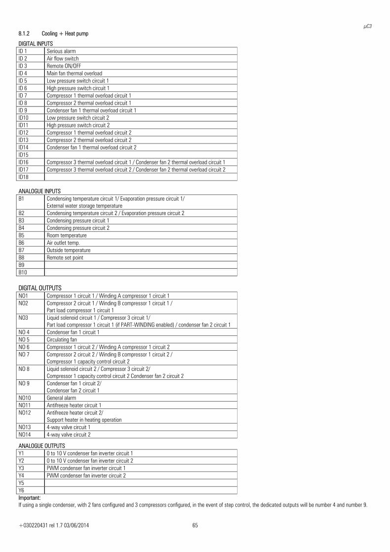
μC3
+030220431 rel 1.7 03/06/2014 65
8.1.2 Cooling + Heat pump
DIGITAL INPUTS ID 1 Serious alarm ID 2 Air flow switch ID 3 Remote ON/OFF ID 4 Main fan thermal overload ID 5 Low pressure switch circuit 1 ID 6 High pressure switch circuit 1 ID 7 Compressor 1 thermal overload circuit 1 ID 8 Compressor 2 thermal overload circuit 1 ID 9 Condenser fan 1 thermal overload circuit 1 ID10 Low pressure switch circuit 2 ID11 High pressure switch circuit 2 ID12 Compressor 1 thermal overload circuit 2 ID13 Compressor 2 thermal overload circuit 2 ID14 Condenser fan 1 thermal overload circuit 2 ID15 ID16 Compressor 3 thermal overload circuit 1 / Condenser fan 2 thermal overload circuit 1 ID17 Compressor 3 thermal overload circuit 2 / Condenser fan 2 thermal overload circuit 2 ID18
ANALOGUE INPUTS B1 Condensing temperature circuit 1/ Evaporation pressure circuit 1/
External water storage temperature B2 Condensing temperature circuit 2 / Evaporation pressure circuit 2 B3 Condensing pressure circuit 1 B4 Condensing pressure circuit 2 B5 Room temperature B6 Air outlet temp. B7 Outside temperature B8 Remote set point B9 B10 DIGITAL OUTPUTS NO1 Compressor 1 circuit 1 / Winding A compressor 1 circuit 1 NO2 Compressor 2 circuit 1 / Winding B compressor 1 circuit 1 /
Part load compressor 1 circuit 1 NO3 Liquid solenoid circuit 1 / Compressor 3 circuit 1/
Part load compressor 1 circuit 1 (if PART-WINDING enabled) / condenser fan 2 circuit 1 NO 4 Condenser fan 1 circuit 1 NO 5 Circulating fan NO 6 Compressor 1 circuit 2 / Winding A compressor 1 circuit 2 NO 7 Compressor 2 circuit 2 / Winding B compressor 1 circuit 2 /
Compressor 1 capacity control circuit 2 NO 8 Liquid solenoid circuit 2 / Compressor 3 circuit 2/
Compressor 1 capacity control circuit 2 Condenser fan 2 circuit 2 NO 9 Condenser fan 1 circuit 2/
Condenser fan 2 circuit 1 NO10 General alarm NO11 Antifreeze heater circuit 1 NO12 Antifreeze heater circuit 2/
Support heater in heating operation NO13 4-way valve circuit 1 NO14 4-way valve circuit 2
ANALOGUE OUTPUTS Y1 0 to 10 V condenser fan inverter circuit 1 Y2 0 to 10 V condenser fan inverter circuit 2 Y3 PWM condenser fan inverter circuit 1 Y4 PWM condenser fan inverter circuit 2 Y5 Y6 Important: If using a single condenser, with 2 fans configured and 3 compressors configured, in the event of step control, the dedicated outputs will be number 4 and number 9.
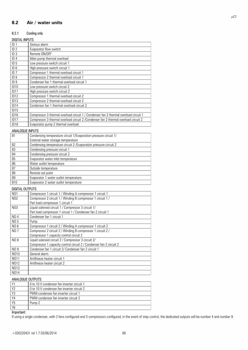
μC3
+030220431 rel 1.7 03/06/2014 66
8.2 Air / water units 8.2.1 Cooling only
DIGITAL INPUTS ID 1 Serious alarm ID 2 Evaporator flow switch ID 3 Remote ON/OFF ID 4 Main pump thermal overload ID 5 Low pressure switch circuit 1 ID 6 High pressure switch circuit 1 ID 7 Compressor 1 thermal overload circuit 1 ID 8 Compressor 2 thermal overload circuit 1 ID 9 Condenser fan 1 thermal overload circuit 1 ID10 Low pressure switch circuit 2 ID11 High pressure switch circuit 2 ID12 Compressor 1 thermal overload circuit 2 ID13 Compressor 2 thermal overload circuit 2 ID14 Condenser fan 1 thermal overload circuit 2 ID15 ID16 Compressor 3 thermal overload circuit 1 / Condenser fan 2 thermal overload circuit 1 ID17 Compressor 3 thermal overload circuit 2 /Condenser fan 2 thermal overload circuit 2 ID18 Evaporator pump 2 thermal overload
ANALOGUE INPUTS B1 Condensing temperature circuit 1/Evaporation pressure circuit 1/
External water storage temperature B2 Condensing temperature circuit 2 /Evaporation pressure circuit 2 B3 Condensing pressure circuit 1 B4 Condensing pressure circuit 2 B5 Evaporator water inlet temperature B6 Water outlet temperature B7 Outside temperature B8 Remote set point B9 Evaporator 1 water outlet temperature B10 Evaporator 2 water outlet temperature
DIGITAL OUTPUTS NO1 Compressor 1 circuit 1 / Winding A compressor 1 circuit 1 NO2 Compressor 2 circuit 1 / Winding B compressor 1 circuit 1 /
Part load compressor 1 circuit 1 NO3 Liquid solenoid circuit 1 / Compressor 3 circuit 1/
Part load compressor 1 circuit 1 / Condenser fan 2 circuit 1 NO 4 Condenser fan 1 circuit 1 NO 5 Pump NO 6 Compressor 1 circuit 2 / Winding A compressor 1 circuit 2 NO 7 Compressor 2 circuit 2 / Winding B compressor 1 circuit 2 /
Compressor 1 capacity control circuit 2 NO 8 Liquid solenoid circuit 2 / Compressor 3 circuit 2/
Compressor 1 capacity control circuit 2 / Condenser fan 2 circuit 2 NO 9 Condenser fan 1 circuit 2/ Condenser fan 2 circuit 1 NO10 General alarm NO11 Antifreeze heater circuit 1 NO12 Antifreeze heater circuit 2 NO13 NO14
ANALOGUE OUTPUTS Y1 0 to 10 V condenser fan inverter circuit 1 Y2 0 to 10 V condenser fan inverter circuit 2 Y3 PWM condenser fan inverter circuit 1 Y4 PWM condenser fan inverter circuit 2 Y5 Pump 2 Y6 Important: If using a single condenser, with 2 fans configured and 3 compressors configured, in the event of step control, the dedicated outputs will be number 4 and number 9.
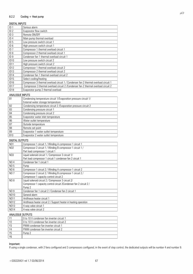
μC3
+030220431 rel 1.7 03/06/2014 67
8.2.2 Cooling + Heat pump DIGITAL INPUTS ID 1 Serious alarm ID 2 Evaporator flow switch ID 3 Remote ON/OFF ID 4 Main pump thermal overload ID 5 Low pressure switch circuit 1 ID 6 High pressure switch circuit 1 ID 7 Compressor 1 thermal overload circuit 1 ID 8 Compressor 2 thermal overload circuit 1 ID 9 Condenser fan 1 thermal overload circuit 1 ID10 Low pressure switch circuit 2 ID11 High pressure switch circuit 2 ID12 Compressor 1 thermal overload circuit 2 ID13 Compressor 2 thermal overload circuit 2 ID14 Condenser fan 1 thermal overload circuit 2 ID15 Select cooling/heating ID16 Compressor 3 thermal overload circuit 1 / Condenser fan 2 thermal overload circuit 1 ID17 Compressor 3 thermal overload circuit 2 /Condenser fan 2 thermal overload circuit 2 ID18 Evaporator pump 2 thermal overload
ANALOGUE INPUTS B1 Condensing temperature circuit 1/Evaporation pressure circuit 1/
External water storage temperature B2 Condensing temperature circuit 2 /Evaporation pressure circuit 2 B3 Condensing pressure circuit 1 B4 Condensing pressure circuit 2 B5 Evaporator water inlet temperature B6 Water outlet temperature B7 Outside temperature B8 Remote set point B9 Evaporator 1 water outlet temperature B10 Evaporator 2 water outlet temperature
DIGITAL OUTPUTS NO1 Compressor 1 circuit 1 / Winding A compressor 1 circuit 1 NO2 Compressor 2 circuit 1 / Winding B compressor 1 circuit 1 /
Part load compressor 1 circuit 1 NO3 Liquid solenoid circuit 1 / Compressor 3 circuit 1/
Part load compressor 1 circuit 1 condenser fan 2 circuit 1 NO 4 Condenser fan 1 circuit 1 NO 5 Pump NO 6 Compressor 1 circuit 2 / Winding A compressor 1 circuit 2 NO 7 Compressor 2 circuit 2 / Winding B compressor 1 circuit 2 /
Compressor 1 capacity control circuit 2 NO 8 Liquid solenoid circuit 2 / Compressor 3 circuit 2/
Compressor 1 capacity control circuit 2Condenser fan 2 circuit 2 / Pump 2
NO 9 Condenser fan 1 circuit 2 / Condenser fan 2 circuit 1 NO10 General alarm NO11 Antifreeze heater circuit 1 NO12 Antifreeze heater circuit 2 / Support heater in heating operation NO13 4-way valve circuit 1 NO14 4-way valve circuit 2
ANALOGUE OUTPUTS Y1 0 to 10 V condenser fan inverter circuit 1 Y2 0 to 10 V condenser fan inverter circuit 2 Y3 PWM condenser fan inverter circuit 1 Y4 PWM condenser fan inverter circuit 2 Y5 Pump 2 Y6 Important: If using a single condenser, with 2 fans configured and 3 compressors configured, in the event of step control, the dedicated outputs will be number 4 and number 9.
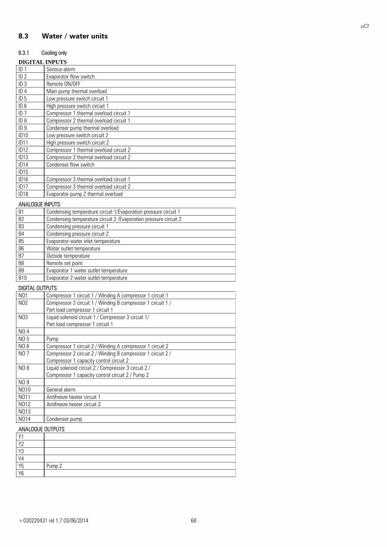
μC3
+030220431 rel 1.7 03/06/2014 68
8.3 Water / water units 8.3.1 Cooling only
DIGITAL INPUTS ID 1 Serious alarm ID 2 Evaporator flow switch ID 3 Remote ON/OFF ID 4 Main pump thermal overload ID 5 Low pressure switch circuit 1 ID 6 High pressure switch circuit 1 ID 7 Compressor 1 thermal overload circuit 1 ID 8 Compressor 2 thermal overload circuit 1 ID 9 Condenser pump thermal overload ID10 Low pressure switch circuit 2 ID11 High pressure switch circuit 2 ID12 Compressor 1 thermal overload circuit 2 ID13 Compressor 2 thermal overload circuit 2 ID14 Condenser flow switch ID15 ID16 Compressor 3 thermal overload circuit 1 ID17 Compressor 3 thermal overload circuit 2 ID18 Evaporator pump 2 thermal overload
ANALOGUE INPUTS B1 Condensing temperature circuit 1/Evaporation pressure circuit 1 B2 Condensing temperature circuit 2 /Evaporation pressure circuit 2 B3 Condensing pressure circuit 1 B4 Condensing pressure circuit 2 B5 Evaporator water inlet temperature B6 Water outlet temperature B7 Outside temperature B8 Remote set point B9 Evaporator 1 water outlet temperature B10 Evaporator 2 water outlet temperature
DIGITAL OUTPUTS NO1 Compressor 1 circuit 1 / Winding A compressor 1 circuit 1 NO2 Compressor 2 circuit 1 / Winding B compressor 1 circuit 1 /
Part load compressor 1 circuit 1 NO3 Liquid solenoid circuit 1 / Compressor 3 circuit 1/
Part load compressor 1 circuit 1 NO 4 NO 5 Pump NO 6 Compressor 1 circuit 2 / Winding A compressor 1 circuit 2 NO 7 Compressor 2 circuit 2 / Winding B compressor 1 circuit 2 /
Compressor 1 capacity control circuit 2 NO 8 Liquid solenoid circuit 2 / Compressor 3 circuit 2 /
Compressor 1 capacity control circuit 2 / Pump 2 NO 9 NO10 General alarm NO11 Antifreeze heater circuit 1 NO12 Antifreeze heater circuit 2 NO13 NO14 Condenser pump
ANALOGUE OUTPUTS Y1 Y2 Y3 Y4 Y5 Pump 2 Y6
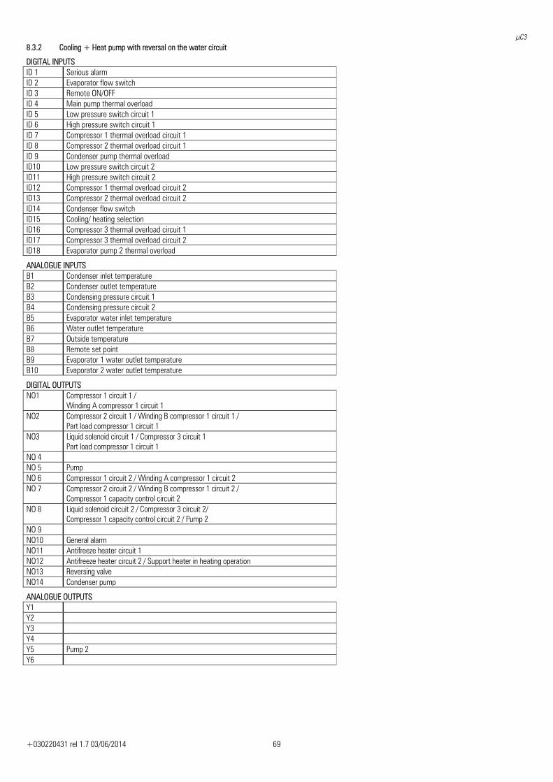
μC3
+030220431 rel 1.7 03/06/2014 69
8.3.2 Cooling + Heat pump with reversal on the water circuit
DIGITAL INPUTS ID 1 Serious alarm ID 2 Evaporator flow switch ID 3 Remote ON/OFF ID 4 Main pump thermal overload ID 5 Low pressure switch circuit 1 ID 6 High pressure switch circuit 1 ID 7 Compressor 1 thermal overload circuit 1 ID 8 Compressor 2 thermal overload circuit 1 ID 9 Condenser pump thermal overload ID10 Low pressure switch circuit 2 ID11 High pressure switch circuit 2 ID12 Compressor 1 thermal overload circuit 2 ID13 Compressor 2 thermal overload circuit 2 ID14 Condenser flow switch ID15 Cooling/ heating selection ID16 Compressor 3 thermal overload circuit 1 ID17 Compressor 3 thermal overload circuit 2 ID18 Evaporator pump 2 thermal overload
ANALOGUE INPUTS B1 Condenser inlet temperature B2 Condenser outlet temperature B3 Condensing pressure circuit 1 B4 Condensing pressure circuit 2 B5 Evaporator water inlet temperature B6 Water outlet temperature B7 Outside temperature B8 Remote set point B9 Evaporator 1 water outlet temperature B10 Evaporator 2 water outlet temperature
DIGITAL OUTPUTS NO1 Compressor 1 circuit 1 /
Winding A compressor 1 circuit 1 NO2 Compressor 2 circuit 1 / Winding B compressor 1 circuit 1 /
Part load compressor 1 circuit 1 NO3 Liquid solenoid circuit 1 / Compressor 3 circuit 1
Part load compressor 1 circuit 1 NO 4 NO 5 Pump NO 6 Compressor 1 circuit 2 / Winding A compressor 1 circuit 2 NO 7 Compressor 2 circuit 2 / Winding B compressor 1 circuit 2 /
Compressor 1 capacity control circuit 2 NO 8 Liquid solenoid circuit 2 / Compressor 3 circuit 2/
Compressor 1 capacity control circuit 2 / Pump 2 NO 9 NO10 General alarm NO11 Antifreeze heater circuit 1 NO12 Antifreeze heater circuit 2 / Support heater in heating operation NO13 Reversing valve NO14 Condenser pump
ANALOGUE OUTPUTS Y1 Y2 Y3 Y4 Y5 Pump 2 Y6
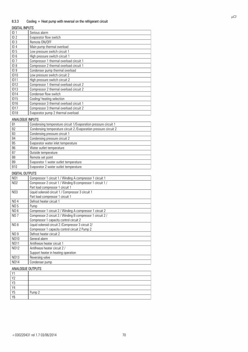
μC3
+030220431 rel 1.7 03/06/2014 70
8.3.3 Cooling + Heat pump with reversal on the refrigerant circuit
DIGITAL INPUTS ID 1 Serious alarm ID 2 Evaporator flow switch ID 3 Remote ON/OFF ID 4 Main pump thermal overload ID 5 Low pressure switch circuit 1 ID 6 High pressure switch circuit 1 ID 7 Compressor 1 thermal overload circuit 1 ID 8 Compressor 2 thermal overload circuit 1 ID 9 Condenser pump thermal overload ID10 Low pressure switch circuit 2 ID11 High pressure switch circuit 2 ID12 Compressor 1 thermal overload circuit 2 ID13 Compressor 2 thermal overload circuit 2 ID14 Condenser flow switch ID15 Cooling/ heating selection ID16 Compressor 3 thermal overload circuit 1 ID17 Compressor 3 thermal overload circuit 2 ID18 Evaporator pump 2 thermal overload
ANALOGUE INPUTS B1 Condensing temperature circuit 1/Evaporation pressure circuit 1 B2 Condensing temperature circuit 2 /Evaporation pressure circuit 2 B3 Condensing pressure circuit 1 B4 Condensing pressure circuit 2 B5 Evaporator water inlet temperature B6 Water outlet temperature B7 Outside temperature B8 Remote set point B9 Evaporator 1 water outlet temperature B10 Evaporator 2 water outlet temperature
DIGITAL OUTPUTS NO1 Compressor 1 circuit 1 / Winding A compressor 1 circuit 1 NO2 Compressor 2 circuit 1 / Winding B compressor 1 circuit 1 /
Part load compressor 1 circuit 1 NO3 Liquid solenoid circuit 1 / Compressor 3 circuit 1
Part load compressor 1 circuit 1 NO 4 Defrost heater circuit 1 NO 5 Pump NO 6 Compressor 1 circuit 2 / Winding A compressor 1 circuit 2 NO 7 Compressor 2 circuit 2 / Winding B compressor 1 circuit 2 /
Compressor 1 capacity control circuit 2 NO 8 Liquid solenoid circuit 2 /Compressor 3 circuit 2/
Compressor 1 capacity control circuit 2 Pump 2 NO 9 Defrost heater circuit 2 NO10 General alarm NO11 Antifreeze heater circuit 1 NO12 Antifreeze heater circuit 2 /
Support heater in heating operation NO13 Reversing valve NO14 Condenser pump
ANALOGUE OUTPUTS Y1 Y2 Y3 Y4 Y5 Pump 2 Y6
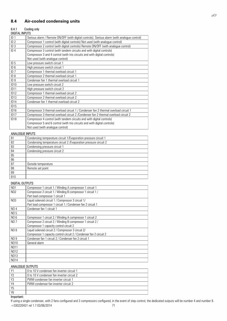
μC3
+030220431 rel 1.7 03/06/2014 71
8.4 Air-cooled condensing units
8.4.1 Cooling only DIGITAL INPUTS ID 1 Serious alarm / Remote ON/OFF (with digital controls). Serious alarm (with analogue control) ID 2 Compressor 1 control (with digital controls) Not used (with analogue control) ID 3 Compressor 2 control (with digital controls) Remote ON/OFF (with analogue control) ID 4 Compressor 3 control (with tandem circuits and with digital controls)
Compressor 3 and 4 control (with trio circuits and with digital controls) Not used (with analogue control)
ID 5 Low pressure switch circuit 1 ID 6 High pressure switch circuit 1 ID 7 Compressor 1 thermal overload circuit 1 ID 8 Compressor 2 thermal overload circuit 1 ID 9 Condenser fan 1 thermal overload circuit 1 ID10 Low pressure switch circuit 2 ID11 High pressure switch circuit 2 ID12 Compressor 1 thermal overload circuit 2 ID13 Compressor 2 thermal overload circuit 2 ID14 Condenser fan 1 thermal overload circuit 2 ID15 ID16 Compressor 3 thermal overload circuit 1 / Condenser fan 2 thermal overload circuit 1 ID17 Compressor 3 thermal overload circuit 2 /Condenser fan 2 thermal overload circuit 2 ID18 Compressor 4 control (with tandem circuits and with digital controls)
Compressor 5 and 6 control (with trio circuits and with digital controls) Not used (with analogue control)
ANALOGUE INPUTS B1 Condensing temperature circuit 1/Evaporation pressure circuit 1 B2 Condensing temperature circuit 2 /Evaporation pressure circuit 2 B3 Condensing pressure circuit 1 B4 Condensing pressure circuit 2 B5 B6 B7 Outside temperature B8 Remote set point B9 B10
DIGITAL OUTPUTS NO1 Compressor 1 circuit 1 / Winding A compressor 1 circuit 1 NO2 Compressor 2 circuit 1 / Winding B compressor 1 circuit 1 /
Part load compressor 1 circuit 1 NO3 Liquid solenoid circuit 1 / Compressor 3 circuit 1/
Part load compressor 1 circuit 1 / Condenser fan 2 circuit 1 NO 4 Condenser fan 1 circuit 1 NO 5 NO 6 Compressor 1 circuit 2 / Winding A compressor 1 circuit 2 NO 7 Compressor 2 circuit 2 / Winding B compressor 1 circuit 2 /
Compressor 1 capacity control circuit 2 NO 8 Liquid solenoid circuit 2 / Compressor 3 circuit 2/
Compressor 1 capacity control circuit 2 / Condenser fan 2 circuit 2 NO 9 Condenser fan 1 circuit 2 / Condenser fan 2 circuit 1 NO10 General alarm NO11 NO12 NO13 NO14
ANALOGUE OUTPUTS Y1 0 to 10 V condenser fan inverter circuit 1 Y2 0 to 10 V condenser fan inverter circuit 2 Y3 PWM condenser fan inverter circuit 1 Y4 PWM condenser fan inverter circuit 2 Y5 Y6 Important: If using a single condenser, with 2 fans configured and 3 compressors configured, in the event of step control, the dedicated outputs will be number 4 and number 9.
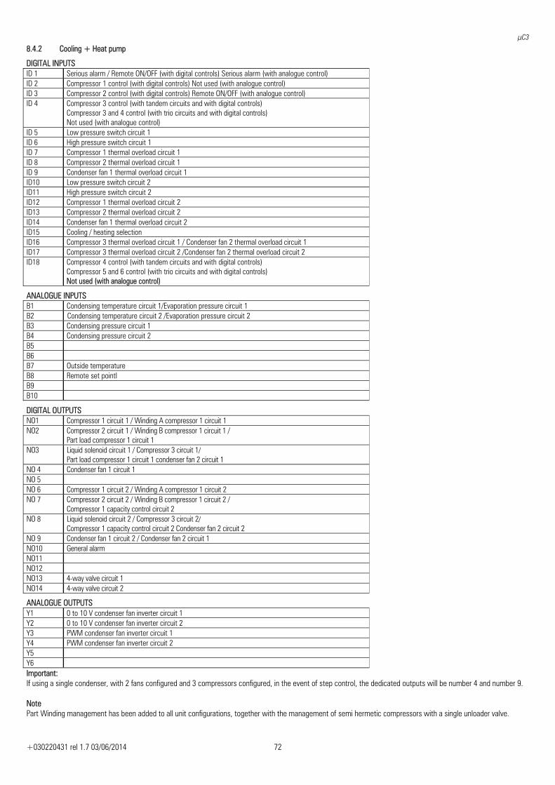
μC3
+030220431 rel 1.7 03/06/2014 72
8.4.2 Cooling + Heat pump
DIGITAL INPUTS ID 1 Serious alarm / Remote ON/OFF (with digital controls) Serious alarm (with analogue control)ID 2 Compressor 1 control (with digital controls) Not used (with analogue control)ID 3 Compressor 2 control (with digital controls) Remote ON/OFF (with analogue control)ID 4 Compressor 3 control (with tandem circuits and with digital controls)
Compressor 3 and 4 control (with trio circuits and with digital controls) Not used (with analogue control)
ID 5 Low pressure switch circuit 1 ID 6 High pressure switch circuit 1 ID 7 Compressor 1 thermal overload circuit 1 ID 8 Compressor 2 thermal overload circuit 1 ID 9 Condenser fan 1 thermal overload circuit 1 ID10 Low pressure switch circuit 2 ID11 High pressure switch circuit 2 ID12 Compressor 1 thermal overload circuit 2 ID13 Compressor 2 thermal overload circuit 2 ID14 Condenser fan 1 thermal overload circuit 2 ID15 Cooling / heating selection ID16 Compressor 3 thermal overload circuit 1 / Condenser fan 2 thermal overload circuit 1ID17 Compressor 3 thermal overload circuit 2 /Condenser fan 2 thermal overload circuit 2ID18 Compressor 4 control (with tandem circuits and with digital controls)
Compressor 5 and 6 control (with trio circuits and with digital controls) Not used (with analogue control)
ANALOGUE INPUTS B1 Condensing temperature circuit 1/Evaporation pressure circuit 1B2 Condensing temperature circuit 2 /Evaporation pressure circuit 2B3 Condensing pressure circuit 1 B4 Condensing pressure circuit 2 B5 B6 B7 Outside temperature B8 Remote set pointl B9 B10
DIGITAL OUTPUTS NO1 Compressor 1 circuit 1 / Winding A compressor 1 circuit 1 NO2 Compressor 2 circuit 1 / Winding B compressor 1 circuit 1 /
Part load compressor 1 circuit 1 NO3 Liquid solenoid circuit 1 / Compressor 3 circuit 1/
Part load compressor 1 circuit 1 condenser fan 2 circuit 1 NO 4 Condenser fan 1 circuit 1 NO 5 NO 6 Compressor 1 circuit 2 / Winding A compressor 1 circuit 2 NO 7 Compressor 2 circuit 2 / Winding B compressor 1 circuit 2 /
Compressor 1 capacity control circuit 2 NO 8 Liquid solenoid circuit 2 / Compressor 3 circuit 2/
Compressor 1 capacity control circuit 2 Condenser fan 2 circuit 2 NO 9 Condenser fan 1 circuit 2 / Condenser fan 2 circuit 1 NO10 General alarm NO11 NO12 NO13 4-way valve circuit 1 NO14 4-way valve circuit 2
ANALOGUE OUTPUTS Y1 0 to 10 V condenser fan inverter circuit 1 Y2 0 to 10 V condenser fan inverter circuit 2 Y3 PWM condenser fan inverter circuit 1 Y4 PWM condenser fan inverter circuit 2 Y5 Y6 Important: If using a single condenser, with 2 fans configured and 3 compressors configured, in the event of step control, the dedicated outputs will be number 4 and number 9. Note Part Winding management has been added to all unit configurations, together with the management of semi hermetic compressors with a single unloader valve.
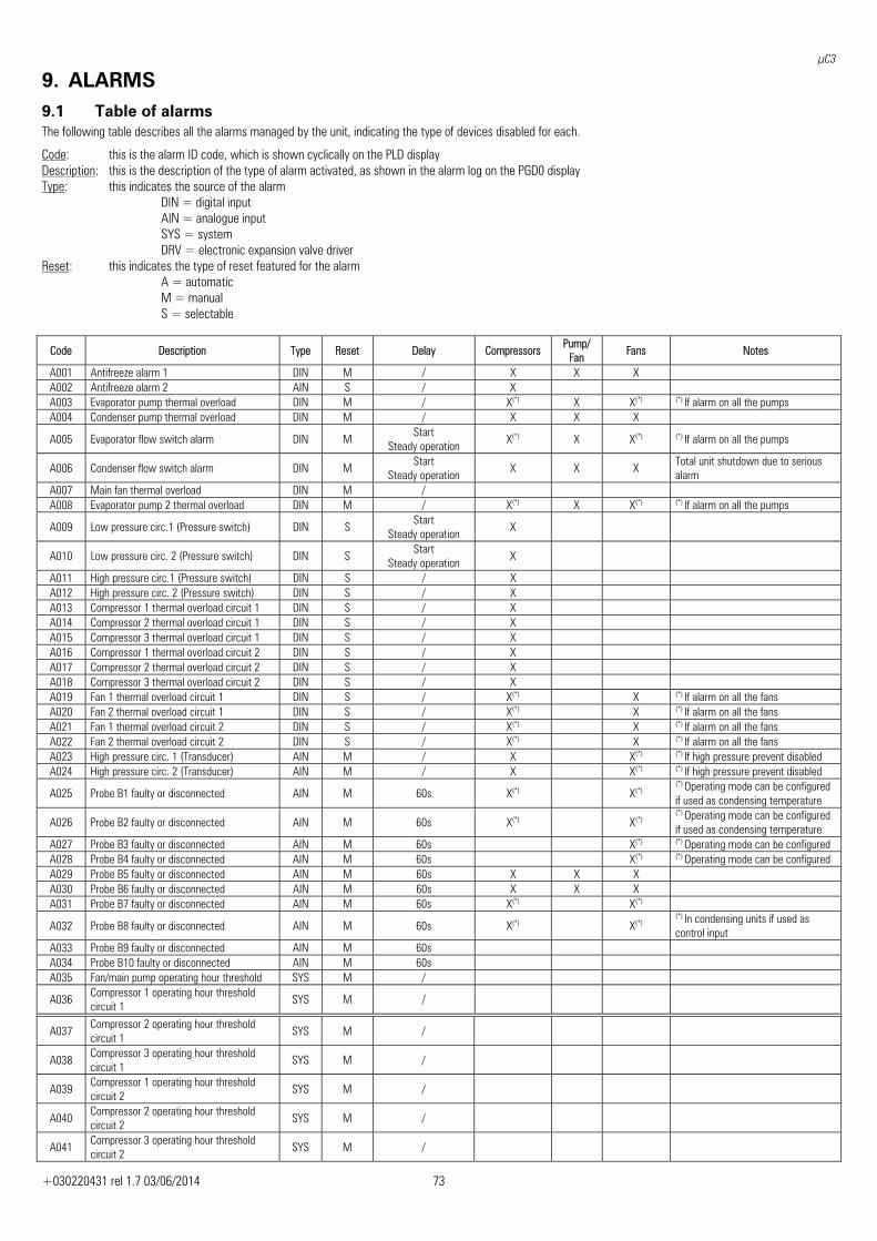
μC3
+030220431 rel 1.7 03/06/2014 73
9. ALARMS 9.1 Table of alarms The following table describes all the alarms managed by the unit, indicating the type of devices disabled for each.
Code: this is the alarm ID code, which is shown cyclically on the PLD display Description: this is the description of the type of alarm activated, as shown in the alarm log on the PGD0 displayType: this indicates the source of the alarm
DIN = digital input AIN = analogue input SYS = system DRV = electronic expansion valve driver
Reset: this indicates the type of reset featured for the alarm A = automatic M = manual S = selectable
Code Description Type Reset Delay Compressors Pump/
Fan Fans Notes
A001 Antifreeze alarm 1 DIN M / X X X A002 Antifreeze alarm 2 AIN S / X A003 Evaporator pump thermal overload DIN M / X(*) X X(*)
(*) If alarm on all the pumps
A004 Condenser pump thermal overload DIN M / X X X
A005 Evaporator flow switch alarm DIN M Start
Steady operation X(*) X X(*)
(*) If alarm on all the pumps
A006 Condenser flow switch alarm DIN M Start
Steady operation X X X Total unit shutdown due to serious alarm
A007 Main fan thermal overload DIN M / A008 Evaporator pump 2 thermal overload DIN M / X(*) X X(*)
(*) If alarm on all the pumps
A009 Low pressure circ.1 (Pressure switch) DIN S Start
Steady operation X
A010 Low pressure circ. 2 (Pressure switch) DIN S Start
Steady operation X
A011 High pressure circ.1 (Pressure switch) DIN S / X A012 High pressure circ. 2 (Pressure switch) DIN S / X A013 Compressor 1 thermal overload circuit 1 DIN S / X A014 Compressor 2 thermal overload circuit 1 DIN S / X A015 Compressor 3 thermal overload circuit 1 DIN S / X A016 Compressor 1 thermal overload circuit 2 DIN S / X A017 Compressor 2 thermal overload circuit 2 DIN S / X A018 Compressor 3 thermal overload circuit 2 DIN S / X A019 Fan 1 thermal overload circuit 1 DIN S / X(*) X (*) If alarm on all the fans A020 Fan 2 thermal overload circuit 1 DIN S / X(*) X (*) If alarm on all the fans A021 Fan 1 thermal overload circuit 2 DIN S / X(*) X (*) If alarm on all the fans A022 Fan 2 thermal overload circuit 2 DIN S / X(*) X (*) If alarm on all the fans A023 High pressure circ. 1 (Transducer) AIN M / X X(*)
(*) If high pressure prevent disabled
A024 High pressure circ. 2 (Transducer) AIN M / X X(*)
(*) If high pressure prevent disabled
A025 Probe B1 faulty or disconnected AIN M 60s X(*) X(*)
(*) Operating mode can be configured if used as condensing temperature
A026 Probe B2 faulty or disconnected AIN M 60s X(*) X(*)
(*) Operating mode can be configured if used as condensing temperature
A027 Probe B3 faulty or disconnected AIN M 60s X(*)
(*) Operating mode can be configured A028 Probe B4 faulty or disconnected AIN M 60s X(*)
(*) Operating mode can be configured
A029 Probe B5 faulty or disconnected AIN M 60s X X X A030 Probe B6 faulty or disconnected AIN M 60s X X X A031 Probe B7 faulty or disconnected AIN M 60s X(*) X(*)
A032 Probe B8 faulty or disconnected AIN M 60s X(*) X(*)
(*) In condensing units if used as control input
A033 Probe B9 faulty or disconnected AIN M 60s A034 Probe B10 faulty or disconnected AIN M 60s A035 Fan/main pump operating hour threshold SYS M /
A036 Compressor 1 operating hour threshold circuit 1
SYS M /
A037 Compressor 2 operating hour threshold circuit 1
SYS M /
A038 Compressor 3 operating hour threshold circuit 1
SYS M /
A039 Compressor 1 operating hour threshold circuit 2
SYS M /
A040 Compressor 2 operating hour threshold circuit 2
SYS M /
A041 Compressor 3 operating hour threshold circuit 2
SYS M /
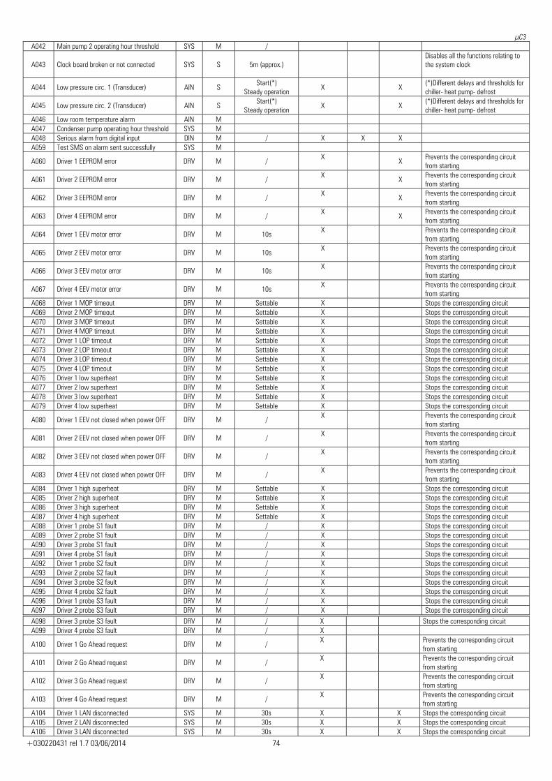
μC3
+030220431 rel 1.7 03/06/2014 74
A042 Main pump 2 operating hour threshold SYS M /
A043 Clock board broken or not connected SYS S 5m (approx.) Disables all the functions relating to the system clock
A044 Low pressure circ. 1 (Transducer) AIN S Start(*)
Steady operation X X
(*)Different delays and thresholds for chiller- heat pump- defrost
A045 Low pressure circ. 2 (Transducer) AIN S Start(*)
Steady operation X X
(*)Different delays and thresholds for chiller- heat pump- defrost
A046 Low room temperature alarm AIN M A047 Condenser pump operating hour threshold SYS M A048 Serious alarm from digital input DIN M / X X X A059 Test SMS on alarm sent successfully SYS M
A060 Driver 1 EEPROM error DRV M / X
X Prevents the corresponding circuit from starting
A061 Driver 2 EEPROM error DRV M / X
X Prevents the corresponding circuit from starting
A062 Driver 3 EEPROM error DRV M / X
X Prevents the corresponding circuit from starting
A063 Driver 4 EEPROM error DRV M / X
X Prevents the corresponding circuit from starting
A064 Driver 1 EEV motor error DRV M 10s X
Prevents the corresponding circuit from starting
A065 Driver 2 EEV motor error DRV M 10s X
Prevents the corresponding circuit from starting
A066 Driver 3 EEV motor error DRV M 10s X
Prevents the corresponding circuit from starting
A067 Driver 4 EEV motor error DRV M 10s X
Prevents the corresponding circuit from starting
A068 Driver 1 MOP timeout DRV M Settable X Stops the corresponding circuit A069 Driver 2 MOP timeout DRV M Settable X Stops the corresponding circuit A070 Driver 3 MOP timeout DRV M Settable X Stops the corresponding circuit A071 Driver 4 MOP timeout DRV M Settable X Stops the corresponding circuit A072 Driver 1 LOP timeout DRV M Settable X Stops the corresponding circuit A073 Driver 2 LOP timeout DRV M Settable X Stops the corresponding circuit A074 Driver 3 LOP timeout DRV M Settable X Stops the corresponding circuit A075 Driver 4 LOP timeout DRV M Settable X Stops the corresponding circuit A076 Driver 1 low superheat DRV M Settable X Stops the corresponding circuit A077 Driver 2 low superheat DRV M Settable X Stops the corresponding circuit A078 Driver 3 low superheat DRV M Settable X Stops the corresponding circuit A079 Driver 4 low superheat DRV M Settable X Stops the corresponding circuit
A080 Driver 1 EEV not closed when power OFF DRV M / X
Prevents the corresponding circuit from starting
A081 Driver 2 EEV not closed when power OFF DRV M / X
Prevents the corresponding circuit from starting
A082 Driver 3 EEV not closed when power OFF DRV M / X
Prevents the corresponding circuit from starting
A083 Driver 4 EEV not closed when power OFF DRV M / X
Prevents the corresponding circuit from starting
A084 Driver 1 high superheat DRV M Settable X Stops the corresponding circuit A085 Driver 2 high superheat DRV M Settable X Stops the corresponding circuit A086 Driver 3 high superheat DRV M Settable X Stops the corresponding circuit A087 Driver 4 high superheat DRV M Settable X Stops the corresponding circuit A088 Driver 1 probe S1 fault DRV M / X Stops the corresponding circuit A089 Driver 2 probe S1 fault DRV M / X Stops the corresponding circuit A090 Driver 3 probe S1 fault DRV M / X Stops the corresponding circuit A091 Driver 4 probe S1 fault DRV M / X Stops the corresponding circuit A092 Driver 1 probe S2 fault DRV M / X Stops the corresponding circuit A093 Driver 2 probe S2 fault DRV M / X Stops the corresponding circuit A094 Driver 3 probe S2 fault DRV M / X Stops the corresponding circuit A095 Driver 4 probe S2 fault DRV M / X Stops the corresponding circuit A096 Driver 1 probe S3 fault DRV M / X Stops the corresponding circuit A097 Driver 2 probe S3 fault DRV M / X Stops the corresponding circuit
A098 Driver 3 probe S3 fault DRV M / X Stops the corresponding circuit A099 Driver 4 probe S3 fault DRV M / X
A100 Driver 1 Go Ahead request DRV M / X
Prevents the corresponding circuit from starting
A101 Driver 2 Go Ahead request DRV M / X
Prevents the corresponding circuit from starting
A102 Driver 3 Go Ahead request DRV M / X
Prevents the corresponding circuit from starting
A103 Driver 4 Go Ahead request DRV M / X
Prevents the corresponding circuit from starting
A104 Driver 1 LAN disconnected SYS M 30s X X Stops the corresponding circuit A105 Driver 2 LAN disconnected SYS M 30s X X Stops the corresponding circuit A106 Driver 3 LAN disconnected SYS M 30s X X Stops the corresponding circuit
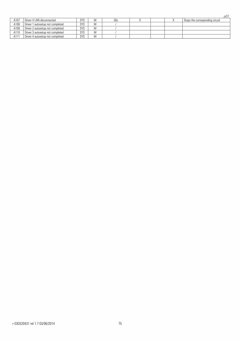
μC3
+030220431 rel 1.7 03/06/2014 75
A107 Driver 4 LAN disconnected SYS M 30s X X Stops the corresponding circuit A108 Driver 1 autosetup not completed SYS M / A109 Driver 2 autosetup not completed SYS M / A110 Driver 3 autosetup not completed SYS M / A111 Driver 4 autosetup not completed SYS M /
μC3
+030220431 rel 1.7 03/06/2014 76
9.2 Type of alarm reset The reset mode can be set for some of the alarms listed in the table, choosing between automatic and manual:
o Compressor thermal overload o Fan thermal overload o Low pressure from transducer and/or pressure switch o High pressure from transducer and/or pressure switch
If automatic reset is selected, a maximum number of events with automatic reset and maximum period of validity can be set, with the time counted from the activation of the first alarm. If after this period the maximum number of repeats of a certain event is not reached, the timer is reset and the next alarm will start a new count. If the maximum number N of repeats set is reached within the set time, then the next event (N+1) will be with manual reset, requiring the operator to intervene to restore the operation of the unit. If manual reset is set, then each alarm event requires the intervention of the operator to restore the operation of the unit.
9.3 Alarm log The alarm log is included to save the fundamental unit operating values in response to certain events.
9.4 Flow switch alarm Inputs used
• Air flow switch (air/air units) Evaporator water flow switch
[B12]
Parameters used • Number of evaporator pumps [-H-] • Evaporator flow switch alarm delay at start-up [P1] • Evaporator flow switch alarm delay in steady operation [P2]
Outputs used • Evaporator pump 1 [B33] • Evaporator pump 2 [B36] • Generic alarm [B38]
The evaporator flow switch alarm disables the operation of the unit if there is no water or air in the main exchanger, so as to prevent dangerous operating conditions with the compressors on and no water or air flow. In Air/water or Water/water units, if control of the second circulating pump is enabled, as the flow switch alarm will cause the rotation of the pump in operation, the program will attempt to recover the situation by starting the reserve device. The alarm management features two delay times before activation:
• when the water circuit is first started • when the unit is in steady operation
The activation of the reserve pump to restore an alarm situation resets the delay in steady operation, after which any new alarm condition will cause the unit to shut down due to a serious water flow problem. In general, with the reserve circulating pump enabled, the flow switch alarm can be activated two times in a row, after which the unit is switched off due to the alarm.
μC3
+030220431 rel 1.7 03/06/2014 77
9.5 Circulating pump thermal overload alarm Inputs used
• Evaporator pump 1 thermal overload [B14] • Evaporator pump 2 thermal overload [B28]
Parameters used • Number evaporator pumps [-H-]
Outputs used • Evaporator pump 1 [B33] • Evaporator pump 2 [B36] • Generic alarm [B38]
The circulating pump thermal overload alarm disables the operation of the device, causing the unit to shutdown immediately, so as to prevent dangerous operating conditions with the compressors on and no water flow. If control of the second circulating pump is enabled, as the thermal alarm will cause the rotation of the pump in operation, the program will attempt to recover the situation by starting the reserve device. Should there also be a thermal overload alarm on this device too, the unit will shutdown immediately. In general, if in response to a thermal overload alarm a different pump cannot be started as support, the unit is switched off.
9.6 Condenser fan thermal overload alarm Inputs used
• Condenser fan 1 thermal overload circuit 1 [B19] • Condenser fan 2 thermal overload circuit 1 (1 condenser) [B24] • Condenser fan 2 thermal overload circuit 1 (2 condensers, 4 fans) [B26] • Condenser fan 1 thermal overload circuit 2 (2 condensers) [B24] • Condenser fan 2 thermal overload circuit 2 (2 condensers, 4 fans) [B27]
Parameters used • Number of condensers installed [-F-] • Total number of fans installed [-F-]
Outputs used • Fan 1 circuit 1 [B32] • Fan 2 circuit 1 [B31] • Fan 2 circuit 1 (single condenser) [B37] • Fan 1 circuit 2 (2 condensers) [B37] • Fan 2 circuit 2 [B36]
The purpose of an individual thermal overload alarm is to prevent the operation of the corresponding device. The alarm affects the operation of the refrigerant circuit in different ways. In general, if in a certain refrigerant circuit, due to one or more alarms the condenser fans are no longer available, then the compressors are also switched off, thus stopping the circuit, so as to avoid dangerous situations of high pressure in the condenser.
9.7 Antifreeze alarm The activation of the antifreeze alarm is based on a set point and differential; if the water temperature falls below the set point, the compressors are stopped immediately, while the pump remains on to prevent the formation of ice. The devices can only be restarted if the water temperature rises above the alarm set point + differential. The set point for the antifreeze alarm is limited by minimum and maximum values, protected by manufacturer password, so as to prevent the values being set at dangerous extreme unit operating conditions. The alarm reset can be defined as manual or automatic: Manual reset: the activation of the antifreeze protection is delayed by a set time (in minutes) from when the unit starts, to allow the unit time to move the water and reach steady operation; the alarm causes the devices to shutdown as described and requires the operator to reset the unit from the user terminal; the unit will only restart if the temperature has returned above the alarm set point + differential. Automatic reset: the activation of the antifreeze protection causes the devices to shutdown as described, and does not require any action by the operator to reset the operation of the unit; as soon as the temperature rises above the alarm set point + differential, the unit will restart automatically. A start-up configuration can be defined for the devices in the event of antifreeze alarms when the unit is off. This function applies only to air/water and water/water units, with the following options: DISABLED: the function is disabled, consequently no load switches in response to an antifreeze alarm HEAT & PUMP ON: in response to an antifreeze alarm, the antifreeze heater and the circulating pump are started HEAT & UNIT ON: in response to an antifreeze alarm, the antifreeze heater and the entire unit are started in heat pump mode, if operation in heating mode is featured HEATER ONLY ON: in response to an antifreeze alarm, the antifreeze heater/heaters are started.
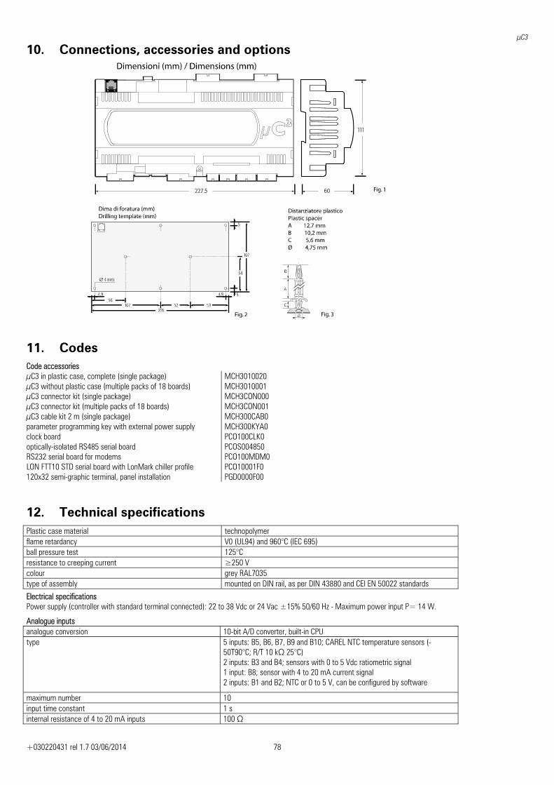
μC3
+030220431 rel 1.7 03/06/2014 78
10. Connections, accessories and options
11. Codes Code accessories μC3 in plastic case, complete (single package) MCH3010020 μC3 without plastic case (multiple packs of 18 boards) MCH3010001 μC3 connector kit (single package) MCH3CON000 μC3 connector kit (multiple packs of 18 boards) MCH3CON001 μC3 cable kit 2 m (single package) MCH300CAB0 parameter programming key with external power supply MCH300KYA0 clock board PCO100CLK0 optically-isolated RS485 serial board PCOS004850 RS232 serial board for modems PCO100MDM0 LON FTT10 STD serial board with LonMark chiller profile PCO10001F0 120x32 semi-graphic terminal, panel installation PGD0000F00
12. Technical specifications Plastic case material technopolymer flame retardancy V0 (UL94) and 960°C (IEC 695) ball pressure test 125°C resistance to creeping current ≥250 V colour grey RAL7035 type of assembly mounted on DIN rail, as per DIN 43880 and CEI EN 50022 standards
Electrical specifications Power supply (controller with standard terminal connected): 22 to 38 Vdc or 24 Vac ±15% 50/60 Hz - Maximum power input P= 14 W.
Analogue inputs analogue conversion 10-bit A/D converter, built-in CPU type 5 inputs: B5, B6, B7, B9 and B10; CAREL NTC temperature sensors (-
50T90°C; R/T 10 kΩ 25°C) 2 inputs: B3 and B4; sensors with 0 to 5 Vdc ratiometric signal 1 input: B8; sensor with 4 to 20 mA current signal 2 inputs: B1 and B2; NTC or 0 to 5 V, can be configured by software
maximum number 10 input time constant 1 s internal resistance of 4 to 20 mA inputs 100 Ω
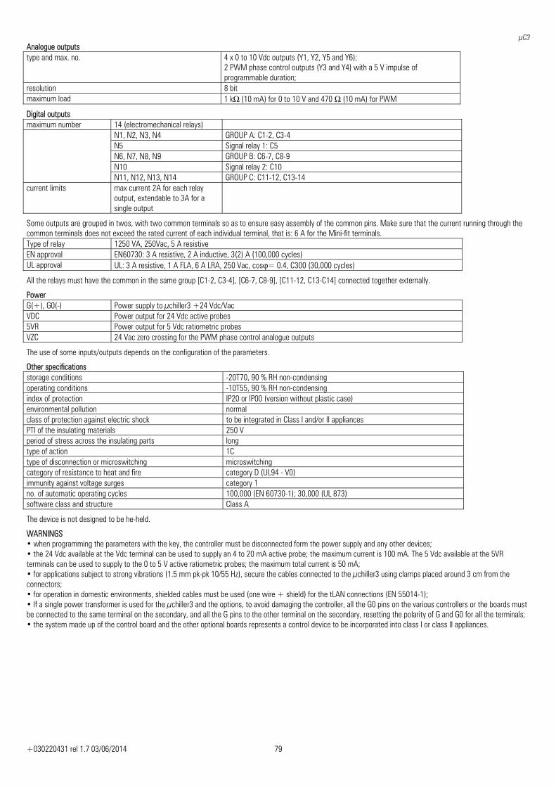
μC3
+030220431 rel 1.7 03/06/2014 79
Analogue outputs type and max. no. 4 x 0 to 10 Vdc outputs (Y1, Y2, Y5 and Y6);
2 PWM phase control outputs (Y3 and Y4) with a 5 V impulse of programmable duration;
resolution 8 bit maximum load 1 kΩ (10 mA) for 0 to 10 V and 470 Ω (10 mA) for PWM
Digital outputs maximum number 14 (electromechanical relays) N1, N2, N3, N4 GROUP A: C1-2, C3-4 N5 Signal relay 1: C5 N6, N7, N8, N9 GROUP B: C6-7, C8-9 N10 Signal relay 2: C10 N11, N12, N13, N14 GROUP C: C11-12, C13-14 current limits max current 2A for each relay
output, extendable to 3A for a single output
Some outputs are grouped in twos, with two common terminals so as to ensure easy assembly of the common pins. Make sure that the current running through the common terminals does not exceed the rated current of each individual terminal, that is: 6 A for the Mini-fit terminals. Type of relay 1250 VA, 250Vac, 5 A resistive EN approval EN60730: 3 A resistive, 2 A inductive, 3(2) A (100,000 cycles) UL approval UL: 3 A resistive, 1 A FLA, 6 A LRA, 250 Vac, cosϕ= 0.4, C300 (30,000 cycles)
All the relays must have the common in the same group [C1-2, C3-4], [C6-7, C8-9], [C11-12, C13-C14] connected together externally.
Power G(+), G0(-) Power supply to μchiller3 +24 Vdc/Vac VDC Power output for 24 Vdc active probes 5VR Power output for 5 Vdc ratiometric probes VZC 24 Vac zero crossing for the PWM phase control analogue outputs
The use of some inputs/outputs depends on the configuration of the parameters.
Other specifications storage conditions -20T70, 90 % RH non-condensing operating conditions -10T55, 90 % RH non-condensing index of protection IP20 or IP00 (version without plastic case) environmental pollution normal class of protection against electric shock to be integrated in Class I and/or II appliances PTI of the insulating materials 250 V period of stress across the insulating parts long type of action 1C type of disconnection or microswitching microswitching category of resistance to heat and fire category D (UL94 - V0) immunity against voltage surges category 1 no. of automatic operating cycles 100,000 (EN 60730-1); 30,000 (UL 873) software class and structure Class A
The device is not designed to be he-held.
WARNINGS • when programming the parameters with the key, the controller must be disconnected form the power supply and any other devices; • the 24 Vdc available at the Vdc terminal can be used to supply an 4 to 20 mA active probe; the maximum current is 100 mA. The 5 Vdc available at the 5VR terminals can be used to supply to the 0 to 5 V active ratiometric probes; the maximum total current is 50 mA; • for applications subject to strong vibrations (1.5 mm pk-pk 10/55 Hz), secure the cables connected to the μchiller3 using clamps placed around 3 cm from the connectors; • for operation in domestic environments, shielded cables must be used (one wire + shield) for the tLAN connections (EN 55014-1); • If a single power transformer is used for the μchiller3 and the options, to avoid damaging the controller, all the G0 pins on the various controllers or the boards must be connected to the same terminal on the secondary, and all the G pins to the other terminal on the secondary, resetting the polarity of G and G0 for all the terminals; • the system made up of the control board and the other optional boards represents a control device to be incorporated into class I or class II appliances.


CAREL HQs Via dell’Industria, 11 - 35020 Brugine - Padova (Italy) Tel. (+39) 049.9716611 Fax (+39) 049.9716600 http://www.carel.com - e-mail: [email protected]
Cod.
+03
0220
431
Rel.
1.7
– 03
/06/
2014