Chemical Mechanical Planarization - Slurry...
4
Customer Application Brief Electronics Chemical Mechanical Planarization - Slurry Distribution System Introduction Chemical Mechanical Planarization (CMP) was introduced into semiconductor manufacturing in the 1980’s as a way to reduce uneven topography on the wafer. The process has been adopted by virtually all semiconductor fabrication facilities producing feature sizes below 0.35 micron. Integrated circuits have multiple levels, or layers of circuitry separated by insulating dielectric layers (ILD). Multilevel layers reproduce up areas and down areas from one level to the next. As each new metal layer gets added it magnifies the layer just below it. As more and more layers are built on the wafer surface the problem with non-planarity (Figure 1) becomes severe i.e. poor step coverage of deposited films and impaired depth of focus of high resolution photolithography. CMP flattens out these uneven areas and allows subsequent photolithography to take place with greater accuracy, which allows film layers to be built up with minimal height variations. CMP enables chipmakers to continue shrinking circuits and extends the performance of lithography tools. This Application Brief reviews the proper filtration methods that can be employed in the Slurry Distribution System to reduce defectivity while increasing yields and overall equipment effectiveness for manufacturers of semiconductor, data storage, and data transmission devices. The CMP Process The CMP process combines the chemical (acidic or basic) effect of the slurry, which contains micro-abrasives with the mechanical effect provided by polishing to reduce topography on the wafer surface. This process uses a “Tool” with a rotating wafer carrier (single or multi-head) and a polishing pad placed on a rotating platen. Wafers are held in the carrier and pressed against the polishing pad onto which chemical abrasive polishing slurry is dispensed (Figure 2). Slurry Distribution System At the semiconductor manufacturing facility, CMP slurry is diluted, mixed and filtered prior to being loaded into a day tank. In some cases the slurry is blended by the supplier and, therefore, only needs to be pumped from the tote to the day tank without any further processing. Slurry is then fed from the day tank to the distribution loop and finally to the CMP tools (Figure 3). Day tanks typically hold 250 - 330 gallons (946 – 1249 liters) of slurry to ensure uninterrupted supply to the CMP tools. The typical flow rate in the distribution loop is 5 - 15 gpm (19 – 57 lpm). From the distribution loop, slurry is fed to each CMP Figure 1 — Ideal Planarization Process Figure 2 — Schematic of the CMP Process Slurry Polishing Head Wafer Polishing Pad Polishing Table Figure 2 — Slurry Distribution Flow Diagram Distribution Filter Concentrated Slurry 1 2 3 3 3 3 Day Tank CMP Tool CMP Tool CMP Tool CMP Tool Slurry Blending Mixing Station Non-Planar Process Possible Fault Ideal Process Oxide Metal N P+ P+ P+ P+ N P+ P+ P+ P+
Transcript of Chemical Mechanical Planarization - Slurry...

Customer Application Brief
Electronics
Chemical Mechanical Planarization -Slurry Distribution SystemIntroductionChemical Mechanical Planarization (CMP) was introduced into semiconductor manufacturing in the 1980’s as a way to reduce uneven topography on the wafer. The process has been adopted by virtually all semiconductor fabrication facilities producing feature sizes below 0.35 micron.
Integrated circuits have multiple levels, or layers of circuitry separated by insulating dielectric layers (ILD). Multilevel layers reproduce up areas and down areas from one level to the next. As each new metal layer gets added it magnifies the layer just below it. As more and more layers are built on the wafer surface the problem with non-planarity (Figure 1) becomes severe i.e. poor step coverage of deposited films and impaired depth of focus of high resolution photolithography. CMP flattens out these uneven areas and allows subsequent photolithography to take place with greater accuracy, which allows film layers to be built up with minimal height variations. CMP enables chipmakers to continue shrinking circuits and extends the performance of lithography tools.
This Application Brief reviews the proper filtration methods that can be employed in the Slurry Distribution System to reduce defectivity while increasing yields and overall equipment effectiveness for manufacturers of semiconductor, data storage, and data transmission devices.
The CMP ProcessThe CMP process combines the chemical (acidic or basic) effect of the slurry, which contains micro-abrasives with the mechanical effect provided by polishing to reduce topography on the wafer surface. This process uses a “Tool” with a rotating wafer carrier (single or multi-head) and a polishing pad placed on a rotating platen. Wafers are held in the carrier and pressed against the polishing pad onto which chemical abrasive polishing slurry is dispensed (Figure 2).
Slurry Distribution SystemAt the semiconductor manufacturing facility, CMP slurry is diluted, mixed and filtered prior to being loaded into a day tank. In some cases the slurry is blended by the supplier and, therefore, only needs to be pumped from the tote to the day tank without any further processing. Slurry is then fed from the day tank to the distribution loop and finally to the CMP tools (Figure 3). Day tanks typically hold 250 - 330 gallons (946 – 1249 liters) of slurry to ensure uninterrupted supply to the CMP tools. The typical flow rate in the distribution loop is 5 - 15 gpm (19 – 57 lpm). From the distribution loop, slurry is fed to each CMP
Figure 1 — Ideal Planarization Process
Figure 2 — Schematic of the CMP Process
Slurry
Polishing Head
Wafer
Polishing Pad
Polishing Table
Figure 2 — Slurry Distribution Flow Diagram
DistributionFilter
ConcentratedSlurry
1
2
3
3 3
3
Day Tank
CMPTool
CMPTool
CMPTool
CMPTool
Slurry BlendingMixing Station
Non-Planar ProcessPossible Fault
Ideal Process
OxideMetal
N
P+ P+ P+ P+
N
P+ P+ P+ P+
tool at a controlled flow rate of 100 - 500 ml (0.026 - 0.132 gallons) per minute. When the CMP process is completed, the distribution piping is rinsed with filtered DI water to avoid the formation of agglomerates while not in use.
The Problem - Large Particle Counts
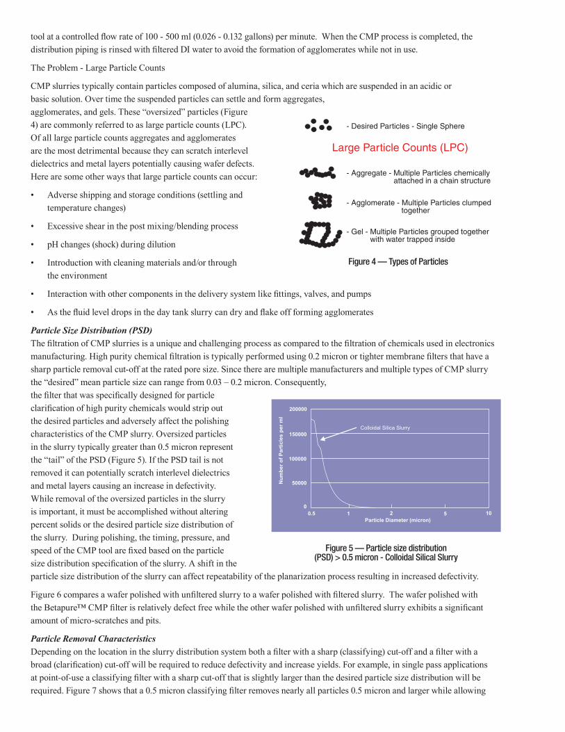
CMP slurries typically contain particles composed of alumina, silica, and ceria which are suspended in an acidic or basic solution. Over time the suspended particles can settle and form aggregates, agglomerates, and gels. These “oversized” particles (Figure 4) are commonly referred to as large particle counts (LPC). Of all large particle counts aggregates and agglomerates are the most detrimental because they can scratch interlevel dielectrics and metal layers potentially causing wafer defects. Here are some other ways that large particle counts can occur:
• Adverse shipping and storage conditions (settling and temperature changes)
• Excessive shear in the post mixing/blending process
• pH changes (shock) during dilution
• Introduction with cleaning materials and/or through the environment
• Interaction with other components in the delivery system like fittings, valves, and pumps
• As the fluid level drops in the day tank slurry can dry and flake off forming agglomerates
Particle Size Distribution (PSD)The filtration of CMP slurries is a unique and challenging process as compared to the filtration of chemicals used in electronics manufacturing. High purity chemical filtration is typically performed using 0.2 micron or tighter membrane filters that have a sharp particle removal cut-off at the rated pore size. Since there are multiple manufacturers and multiple types of CMP slurry the “desired” mean particle size can range from 0.03 – 0.2 micron. Consequently, the filter that was specifically designed for particle clarification of high purity chemicals would strip out the desired particles and adversely affect the polishing characteristics of the CMP slurry. Oversized particles in the slurry typically greater than 0.5 micron represent the “tail” of the PSD (Figure 5). If the PSD tail is not removed it can potentially scratch interlevel dielectrics and metal layers causing an increase in defectivity. While removal of the oversized particles in the slurry is important, it must be accomplished without altering percent solids or the desired particle size distribution of the slurry. During polishing, the timing, pressure, and speed of the CMP tool are fixed based on the particle size distribution specification of the slurry. A shift in the particle size distribution of the slurry can affect repeatability of the planarization process resulting in increased defectivity.
Figure 6 compares a wafer polished with unfiltered slurry to a wafer polished with filtered slurry. The wafer polished with the Betapure™ CMP filter is relatively defect free while the other wafer polished with unfiltered slurry exhibits a significant amount of micro-scratches and pits.
Particle Removal CharacteristicsDepending on the location in the slurry distribution system both a filter with a sharp (classifying) cut-off and a filter with a broad (clarification) cut-off will be required to reduce defectivity and increase yields. For example, in single pass applications at point-of-use a classifying filter with a sharp cut-off that is slightly larger than the desired particle size distribution will be required. Figure 7 shows that a 0.5 micron classifying filter removes nearly all particles 0.5 micron and larger while allowing
Figure 4 — Types of Particles
Figure 5 — Particle size distribution (PSD) > 0.5 micron - Colloidal Silical Slurry
0.5 1 2 5 100
50000
100000
150000
200000
Particle Diameter (micron)
Num
ber o
f Par
ticle
s pe
r ml
Colloidal Silica Slurry
- Desired Particles - Single Sphere
Large Particle Counts (LPC)
- Aggregate - Multiple Particles chemically attached in a chain structure
- Agglomerate - Multiple Particles clumped together
- Gel - Multiple Particles grouped together with water trapped inside

nearly all particles 0.5 micron and smaller to pass through the filter. The proper classifying filter at point-of-use will not remove the desired working size particles or alter percent solids thus preserving the polishing characteristics of the slurry. In the distribution loop, the application requires a clarifying filter with a broad removal range like that depicted in Figure 8. The distribution loop filter should also contain a higher porosity media than at point-of-use as it needs to remove the undesired PSD tail over a wide (0.5 – 3.0) micron range. A higher porosity media will increase flow while reducing pressure drop and fluid shear on the slurry. Increasing flow while maintaining particle removal efficiency results in particle specifications being achieved in less time. Figure 9 shows the particle removal efficiency of an Betapure™ CMP 560 series filter in re-circulation mode over specific time intervals.
“Matching” the slurry to the proper distribution and point-of-use filters will provide the optimum level of performance needed to dramatically reduce defect causing large particles.
The SolutionMajor reductions in large particle counts can directly be associated to proper filtration, resulting in reduced defectivity and improved yields. The proper filtration system requires both a filter design that will “classify” and “clarify” the slurry at point-of-use and point-of-distribution respectively. Graded porosity depth filters are the most efficient and cost effective means of filtering slurries. The varying porosity of the filter media, when properly selected, will retain the oversized particles and allow the desired “working” particles to pass through while maintaining the polishing characteristics of the slurry. Betapure CMP series filters meet these exacting requirements.
The CMP slurry distribution system contains three important filtration points (see Figure 3).
• Location 1 - The post-blending filter ensures that no oversized particles get into the day tank. Large particle counts like gels and agglomerates often stick to the tank bottom and wall. These oversized particles break free during mixing/blending with RODI water and must be removed. It is recommended that Betapure CMP 560 series filters be installed at this location to remove large particles and prevent frequent plugging of the distribution and dispense filters downstream.
• Location 2 - The distribution loop filter acts as a roughing stage for the point-of-use filters. It remains on line filtering and re-circulating slurry back to the day tank when the CMP tool is not in use. This filter will remove large particles that are formed in the distribution loop and day tank. Since, flow rates are higher at this location, a more open or porous grade
Figure 6 — Proper Filtration Reduces Defectivity
Horizon capture of copper wafer surface with no filtration
Horizon capture of copper wafer surface with Betapure™ CMP filtration
Figure 7 — Classifying Filter Figure 8 — Clarifying Filter
Figure 9 — CMP Distribution Loop Filtration - Recirculation Over Time
0.5 1 20
50000
100000
150000
200000
Particle Diameter (micron)
Num
ber
of P
artic
les
per
ml Inlet
10 minute Outlet
60 minute Outlet
120 minute Outlet
180 minute Outlet
Part
icle
Rem
oval
Effi
cien
cy -
%
Particle Size - Micrometers0 0.5 1.0 1.5 2.0 2.5
100
90
80
70
60
50
40
30
20
10
0
Part
icle
Rem
oval
Effi
cien
cy -
%
Particle Size - Micrometers0 0.5 1.0 1.5 2.0 2.5
100
90
80
70
60
50
40
30
20
10
0
3M Purification Inc.400 Research ParkwayMeriden, CT 06450, U.S.A.Tel (800) 243-6894 (203) 237-5541Fax (203) 630-4530www.3Mpurification.com
filter like Betapure™ CPM 550, CMP 560 and CMP570 are recommended for maximum filter life. Proper filtration at this point will extend the life of the point-of-use filters and reduce their change-out frequency.
• Location 3 - The point-of-use filter is the most critical, capturing unwanted oversized particles upstream of the CMP tool. A consistent quality of slurry at point-of-use enables repeatability of the planarization process and ensures that defect causing large particles are not allowed to enter the CMP tool and potentially cause micro-scratches. For superior particle removal in metal slurries Betapure CMP 510 and CMP 520 series filters are recommended whereas in oxide slurries Betapure CMP 520, CMP 530 and CMP 540 series filters are recommended.
“Matching” the characteristics of the slurry to the proper Betapure™ CMP point-of-use and point-of-distribution filters can significantly impact the profitability of the semiconductor manufacturing plant as demonstrated in Table 1.
A. One 8 inch wafer producing 100 dies 100 DIES
B. Each die worth $50
C. Number of wafers produced per CMP tool/month 600 wafers
D. Each wafer worth A x B $5,000
D. Total number of dies worth A x B x C $3,000,000
E. 1.0 % Improvement to yield (D x 0.01 %) $30,000 / month
F. In one year the saving will be E x 12 $360,000 / year
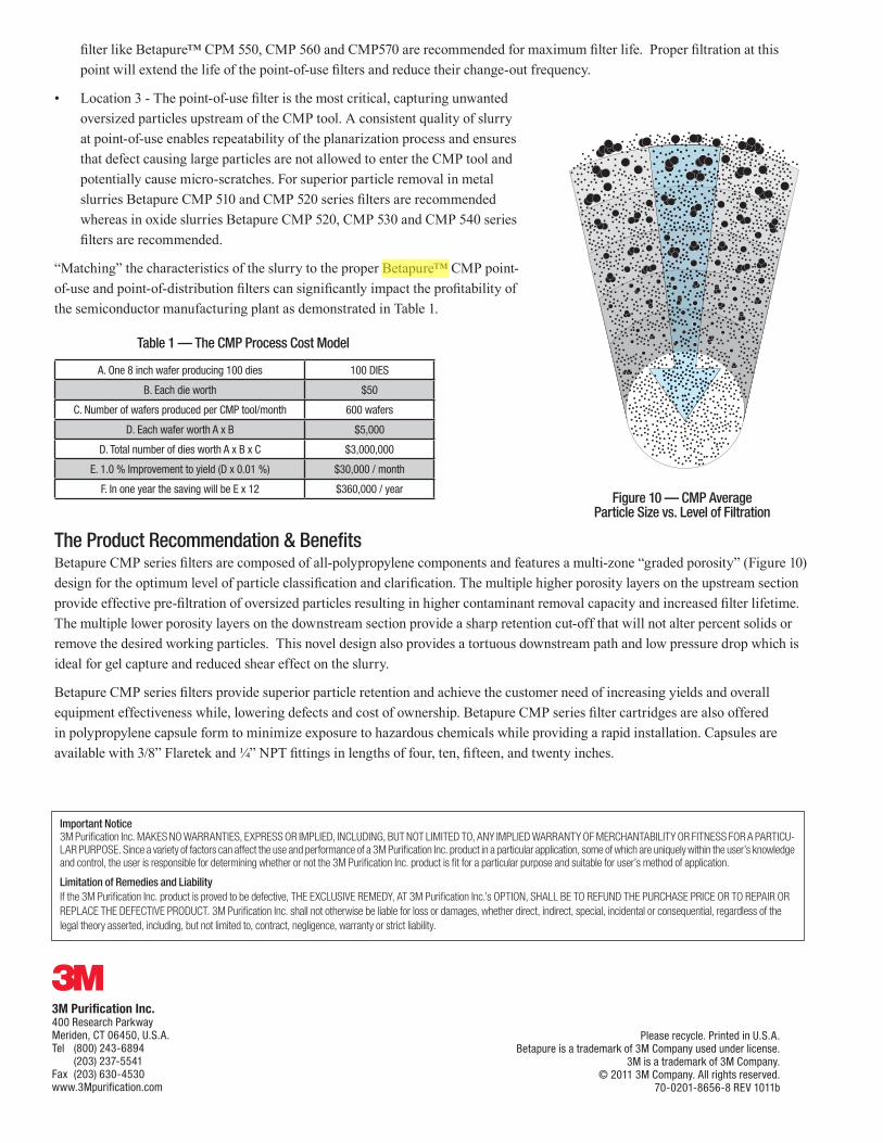
The Product Recommendation & BenefitsBetapure CMP series filters are composed of all-polypropylene components and features a multi-zone “graded porosity” (Figure 10) design for the optimum level of particle classification and clarification. The multiple higher porosity layers on the upstream section provide effective pre-filtration of oversized particles resulting in higher contaminant removal capacity and increased filter lifetime. The multiple lower porosity layers on the downstream section provide a sharp retention cut-off that will not alter percent solids or remove the desired working particles. This novel design also provides a tortuous downstream path and low pressure drop which is ideal for gel capture and reduced shear effect on the slurry.
Betapure CMP series filters provide superior particle retention and achieve the customer need of increasing yields and overall equipment effectiveness while, lowering defects and cost of ownership. Betapure CMP series filter cartridges are also offered in polypropylene capsule form to minimize exposure to hazardous chemicals while providing a rapid installation. Capsules are available with 3/8” Flaretek and ¼” NPT fittings in lengths of four, ten, fifteen, and twenty inches.
Figure 10 — CMP Average Particle Size vs. Level of Filtration
Table 1 — The CMP Process Cost Model
Please recycle. Printed in U.S.A.Betapure is a trademark of 3M Company used under license.
3M is a trademark of 3M Company.© 2011 3M Company. All rights reserved.
70-0201-8656-8 REV 1011b
Important Notice3M Purification Inc. MAKES NO WARRANTIES, EXPRESS OR IMPLIED, INCLUDING, BUT NOT LIMITED TO, ANY IMPLIED WARRANTY OF MERCHANTABILITY OR FITNESS FOR A PARTICU-LAR PURPOSE. Since a variety of factors can affect the use and performance of a 3M Purification Inc. product in a particular application, some of which are uniquely within the user’s knowledge and control, the user is responsible for determining whether or not the 3M Purification Inc. product is fit for a particular purpose and suitable for user’s method of application.
Limitation of Remedies and LiabilityIf the 3M Purification Inc. product is proved to be defective, THE EXCLUSIVE REMEDY, AT 3M Purification Inc.’s OPTION, SHALL BE TO REFUND THE PURCHASE PRICE OR TO REPAIR OR REPLACE THE DEFECTIVE PRODUCT. 3M Purification Inc. shall not otherwise be liable for loss or damages, whether direct, indirect, special, incidental or consequential, regardless of the legal theory asserted, including, but not limited to, contract, negligence, warranty or strict liability.
A0PT4ZZ
Cross-Out
A0PT4ZZ
Highlight