
Characterization and Classification of the NRG Class 1 ... · Characterization and Classification...
19
Renewable NRG Systems | 110 Riggs Road | Hinesburg, VT 05461 | www.renewableNRGsystems.com 5/10/2012 RENEWABLE NRG SYSTEMS Characterization and Classification of the NRG Class 1 Anemometer for IEC 61400‐ 12‐1 Compliance
Transcript of Characterization and Classification of the NRG Class 1 ... · Characterization and Classification...

Renewable NRG Systems | 110 Riggs Road | Hinesburg, VT 05461 | www.renewableNRGsystems.com 5/10/2012
RENEWABLE NRG SYSTEMS
Characterization and Classification of the NRG Class 1 Anemometer for IEC 61400‐12‐1 Compliance
Characterization and Classification of the NRG Class 1 Anemometer for IEC 61400‐12‐1 Compliance
2 Renewable NRG Systems | 110 Riggs Road | Hinesburg, VT 05461 | www.renewableNRGsystems.com
5/10/2012
I. Abstract Under the guidance of Troels Pedersen of DTU Wind Energy Department (formerly RISO National Laboratory), Renewable NRG Systems has characterized and classified the NRG Class 1 Anemometer, a ball bearing version of the NRG #40C Anemometer, according to the guidelines documented in the DTU Wind Energy Department’s Accuwind reports and the IEC 61400‐12‐1 Standard for Power performance measurements of electricity producing wind turbines. Following the Accuwind method and the IEC 61400‐12‐1 Standard, the Classification Indices of the NRG Class 1 Anemometer are 1.01A and 8.44B, as summarized in Table 1 below.
Table 1 Summary of Classification Indices for NRG Class 1 Anemometers
NRG Class 1 Anemometer S/N Class A Index Class B Index
S/N 047 1.07 8.07
S/N 066 0.948 8.80
Average Value 1.01 8.44
This white paper documents the results and supporting work to characterize and classify the NRG Class 1 Anemometer according to the guidelines documented in the DTU Wind Energy Department’s Accuwind reports and the IEC 61400‐12‐1 Standard.

Characterization and Classification of the NRG Class 1 Anemometer for IEC 61400‐12‐1 Compliance
3 Renewable NRG Systems | 110 Riggs Road | Hinesburg, VT 05461 | www.renewableNRGsystems.com
5/10/2012
Table of Contents I. Abstract ............................................................................................................................................. 2
II. Overview of the Anemometer Classification .................................................................................... 4
III. Measured NRG Class 1 Anemometer Input Data .......................................................................... 5
Wind Tunnel Calibration ....................................................................................................................... 5
Angular or Off‐Axis Response ............................................................................................................... 5
Friction .................................................................................................................................................. 7
Torque ................................................................................................................................................... 9
IV. Results ........................................................................................................................................... 9
V. References ...................................................................................................................................... 12
VI. Attachments ................................................................................................................................ 13
Letter certifying classification of NRG Class 1 Anemometer .............................................................. 13
NRGBBO‐047.cup Input File ................................................................................................................ 14
NRGBBO‐066.cup Input File ................................................................................................................ 17

Characterization and Classification of the NRG Class 1 Anemometer for IEC 61400‐12‐1 Compliance
4 Renewable NRG Systems | 110 Riggs Road | Hinesburg, VT 05461 | www.renewableNRGsystems.com
5/10/2012
II. Overview of the Anemometer Classification Anemometer classification is comprised of three (3) main steps:
1. Quantifying the anemometer error subject to influence parameters including dynamic effects (due to wind turbulence), off‐axis (non‐horizontal) wind, and bearing friction effects. The method for quantifying anemometer error is based on the Tilt‐Response & Torque‐Coefficient (TRTC) model described in the DTU Wind Energy Department’s Accuwind report (J.‐Å. Dahlberg, May 2006). The influence parameters and ranges are summarized in Table 2 below.
2. Classifying the anemometer by assigning an index (k) that bounds the maximum anemometer error. The index is quantified using the following equation:
k 100 ⋅ maxε
U2 5m/s
where k is the Classification Index, is the anemometer error in wind speed bin i, is the wind speed in bin i. The denominator in the above equation is the deviation envelope. So a Classification Index is assigned to an anemometer that bounds its maximum wind speed deviation subject to the stated influence parameters.
3. Classifying at least two (2) anemometers to determine the overall Classification Index of the anemometer per IEC 61400‐12‐1 (IEC 61400‐12‐1 Power performance measurements of electricity producing wind turbines). IEC 61400‐12‐1 Annex I states “At least two examples of a type of anemometer shall be assessed” for the classification of anemometry. Averaging the results of the two (2) classifications is an acceptable method for determining the overall anemometer Classification Indices.
Anemometer dynamics, off‐axis response, and bearing friction are measured under laboratory‐controlled conditions (see Section entitled Measured NRG Class 1 Anemometer Input Data for details). These measurements are physical inputs into the TRTC anemometer model which quantifies and bounds the error of the anemometer, subject to the influence parameters. The operational range of the influence parameters are summarized in Table 2. “Class A” corresponds to flat terrain sites; “Class B” corresponds to complex terrain sites. To meet the requirements of IEC 61400‐12‐1, two (2) NRG Class 1 Anemometers (S/N 047 and S/N 066) were characterized to determine the overall anemometer classification through averaging.
Characterization and Classification of the NRG Class 1 Anemometer for IEC 61400‐12‐1 Compliance
5 Renewable NRG Systems | 110 Riggs Road | Hinesburg, VT 05461 | www.renewableNRGsystems.com
5/10/2012
Table 2 Class A and B Operational Ranges
Classification Category
Class A Ideal flat terrain sites
Class B Non‐ideal complex terrain sites
Min Max Min Max
Wind speed range (m/s)
4 16 4 16
Turbulence Intensity 0.03 0.12 + 0.48/V 0.03 0.12 + 0.96/V
Turbulence Structure / /
1/0.8/0.5 Non‐isotropic turbulence
Kaimal wind spectrum with a longitudinal turbulence scale of
350m
1/1/1 Isotropic turbulence
Von Karman wind spectrum with a longitudinal turbulence length scale of
170m
Air Temperature (°C) 0 40 ‐10 40
Air Density (kg/m3) 0.9 1.35 0.9 1.35
Average flow inclination (°)
‐3 3 ‐15 15
III. Measured NRG Class 1 Anemometer Input Data Numerical values of all input data obtained from laboratory tests are included in the NRGBBO‐047.cup and NRGBBO‐066.cup input files (see attachments). The first five lines of the input file contain anemometer property data (cup radius, area, and moment of inertia) as well as calibration slope and offset. After line five, the input file includes three distinct blocks of measured data: torque, friction, and off‐axis response. Data measured on two (2) NRG Class 1 Anemometers (S/N 047 and S/N 066) was used to classify the anemometer. Each of the measured input data is described below.
Wind Tunnel Calibration
The two (2) NRG Class 1 Anemometers were calibrated in Svend Ole Hansen’s (SOH) Measnet‐certified wind tunnel. Calibrations followed the protocol outlined in IEC 61400‐12‐1, Annex F. The calibration values for the two (2) anemometers are reported in Table 3 below.
Table 3 Summary of Calibration Values
NRG Class 1 Anemometer Slope Offset
S/N 047 0.76572 0.19924
S/N 066 0.76645 0.20439
Angular or Off‐Axis Response Off‐axis response of the NRG Class 1 Anemometers was measured in the Svend Ole Hansen (SOH) Measnet‐certified wind tunnel. Off‐axis response measurements were taken statically, and not with
Characterization and Classification of the NRG Class 1 Anemometer for IEC 61400‐12‐1 Compliance
6 Renewable NRG Systems | 110 Riggs Road | Hinesburg, VT 05461 | www.renewableNRGsystems.com
5/10/2012
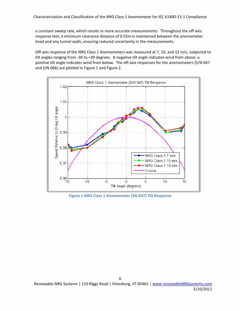
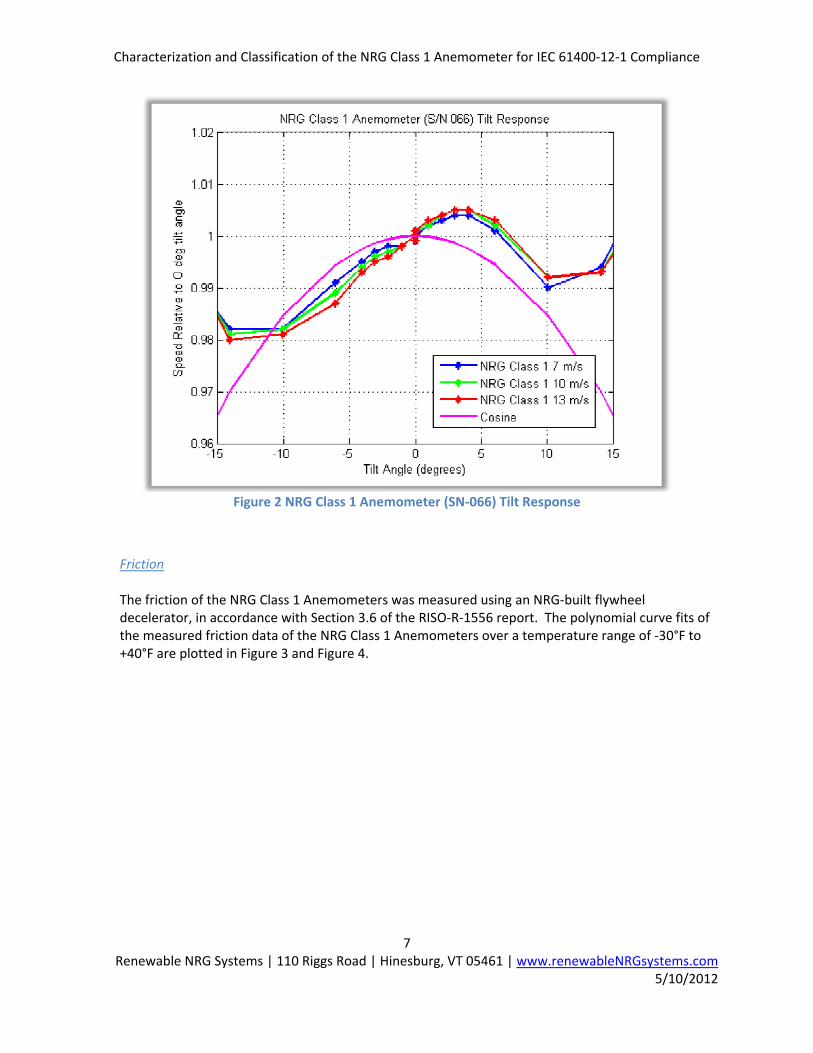
a constant sweep rate, which results in more accurate measurements. Throughout the off‐axis response test, a minimum clearance distance of 0.55m is maintained between the anemometer head and any tunnel walls, ensuring reduced uncertainty in the measurements. Off‐axis response of the NRG Class 1 Anemometers was measured at 7, 10, and 13 m/s, subjected to tilt angles ranging from ‐30 to +30 degrees. A negative tilt angle indicates wind from above; a positive tilt angle indicates wind from below. The off‐axis responses for the anemometers (S/N 047 and S/N 066) are plotted in Figure 1 and Figure 2.
Figure 1 NRG Class 1 Anemometer (SN‐047) Tilt Response
Characterization and Classification of the NRG Class 1 Anemometer for IEC 61400‐12‐1 Compliance
7 Renewable NRG Systems | 110 Riggs Road | Hinesburg, VT 05461 | www.renewableNRGsystems.com
5/10/2012
Figure 2 NRG Class 1 Anemometer (SN‐066) Tilt Response
Friction
The friction of the NRG Class 1 Anemometers was measured using an NRG‐built flywheel decelerator, in accordance with Section 3.6 of the RISO‐R‐1556 report. The polynomial curve fits of the measured friction data of the NRG Class 1 Anemometers over a temperature range of ‐30°F to +40°F are plotted in Figure 3 and Figure 4.

Characterization and Classification of the NRG Class 1 Anemometer for IEC 61400‐12‐1 Compliance
8 Renewable NRG Systems | 110 Riggs Road | Hinesburg, VT 05461 | www.renewableNRGsystems.com
5/10/2012
Figure 3 NRG Class 1 Anemometer (S/N 047) Friction Data
Figure 4 NRG Class 1 Anemometer (S/N 066) Friction Data

Characterization and Classification of the NRG Class 1 Anemometer for IEC 61400‐12‐1 Compliance
9 Renewable NRG Systems | 110 Riggs Road | Hinesburg, VT 05461 | www.renewableNRGsystems.com
5/10/2012
Torque
Measured torque data includes frictional torque plus aerodynamic torque, the latter being the dominant source of torque. Torque data measured on the Rulon bearing NRG #40C anemometer was utilized for the NRG Class 1 Anemometer due to constraints in adjusting the torque data set. Specifically, it was not possible to subtract out the frictional torque from the original DTU Wind Energy Department’s torque data of the NRG #40C Anemometer and subsequently add‐in the frictional torque of the NRG Class 1 Anemometer.
The NRG Class 1 Anemometer employs the identical head as the NRG #40C Anemometer. As such, it is anticipated that the total torque of the NRG Class 1 Anemometer will be close to that of the NRG #40C Anemometer, since the aerodynamic torque dominates the total torque and aerodynamic torque is governed by the anemometer head. The approach of using the NRG #40C torque data for the NRG Class 1 Anemometer is conservative because the NRG Class 1 Anemometer possesses less frictional torque than the NRG #40C. Accounting for the difference in frictional torque would result in a small but improved classification index.
IV. Results Using the measured anemometer data as inputs, AnemCq6.exe, an executable Fortran code supplied by Troels Pedersen of DTU Wind Energy Department, was used to quantify the bounded errors and associated Classification Indices of the NRG Class 1 Anemometer. This is the same program that was used in the Accuwind study. The bounded errors and associated Classification Indices of the NRG Class 1 Anemometers (S/N 047 and S/N 066) are shown in Figure 5 through Figure 8. Figure 5 and Figure 6 show the bounded errors and Classification Indices of the NRG Class 1 Anemometers subject to the Class A operational range of influence parameters. Figure 7 and Figure 8 show the bounded errors and Classification Indices of the NRG Class 1 Anemometers subject to the Class B operational range of influence parameters.

Characterization and Classification of the NRG Class 1 Anemometer for IEC 61400‐12‐1 Compliance
10 Renewable NRG Systems | 110 Riggs Road | Hinesburg, VT 05461 | www.renewableNRGsystems.com
5/10/2012
Figure 5 NRG Class 1 Anemometer (S/N 047) Maximum Deviations Class A
Figure 6 NRG Class 1 Anemometer (S/N 066) Maximum Deviations Class A

Characterization and Classification of the NRG Class 1 Anemometer for IEC 61400‐12‐1 Compliance
11 Renewable NRG Systems | 110 Riggs Road | Hinesburg, VT 05461 | www.renewableNRGsystems.com
5/10/2012
Figure 7 NRG Class 1 Anemometer (S/N 047) Maximum Deviations Class B
Figure 8 NRG Class 1 Anemometer (S/N 066) Maximum Deviations Class B
Characterization and Classification of the NRG Class 1 Anemometer for IEC 61400‐12‐1 Compliance
12 Renewable NRG Systems | 110 Riggs Road | Hinesburg, VT 05461 | www.renewableNRGsystems.com
5/10/2012
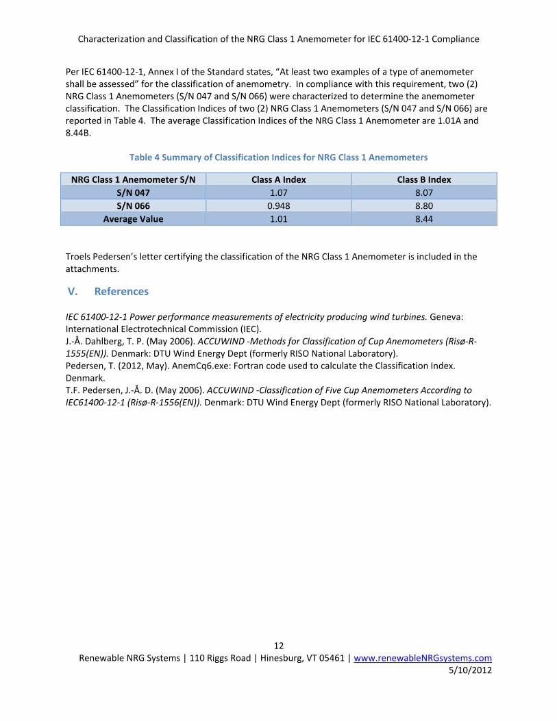
Per IEC 61400‐12‐1, Annex I of the Standard states, “At least two examples of a type of anemometer shall be assessed” for the classification of anemometry. In compliance with this requirement, two (2) NRG Class 1 Anemometers (S/N 047 and S/N 066) were characterized to determine the anemometer classification. The Classification Indices of two (2) NRG Class 1 Anemometers (S/N 047 and S/N 066) are reported in Table 4. The average Classification Indices of the NRG Class 1 Anemometer are 1.01A and 8.44B.
Table 4 Summary of Classification Indices for NRG Class 1 Anemometers
NRG Class 1 Anemometer S/N Class A Index Class B Index
S/N 047 1.07 8.07
S/N 066 0.948 8.80
Average Value 1.01 8.44
Troels Pedersen’s letter certifying the classification of the NRG Class 1 Anemometer is included in the attachments.
V. References IEC 61400‐12‐1 Power performance measurements of electricity producing wind turbines. Geneva: International Electrotechnical Commission (IEC). J.‐Å. Dahlberg, T. P. (May 2006). ACCUWIND ‐Methods for Classification of Cup Anemometers (Risø‐R‐1555(EN)). Denmark: DTU Wind Energy Dept (formerly RISO National Laboratory). Pedersen, T. (2012, May). AnemCq6.exe: Fortran code used to calculate the Classification Index. Denmark. T.F. Pedersen, J.‐Å. D. (May 2006). ACCUWIND ‐Classification of Five Cup Anemometers According to IEC61400‐12‐1 (Risø‐R‐1556(EN)). Denmark: DTU Wind Energy Dept (formerly RISO National Laboratory).
Characterization and Classification of the NRG Class 1 Anemometer for IEC 61400‐12‐1 Compliance
13 Renewable NRG Systems | 110 Riggs Road | Hinesburg, VT 05461 | www.renewableNRGsystems.com
5/10/2012
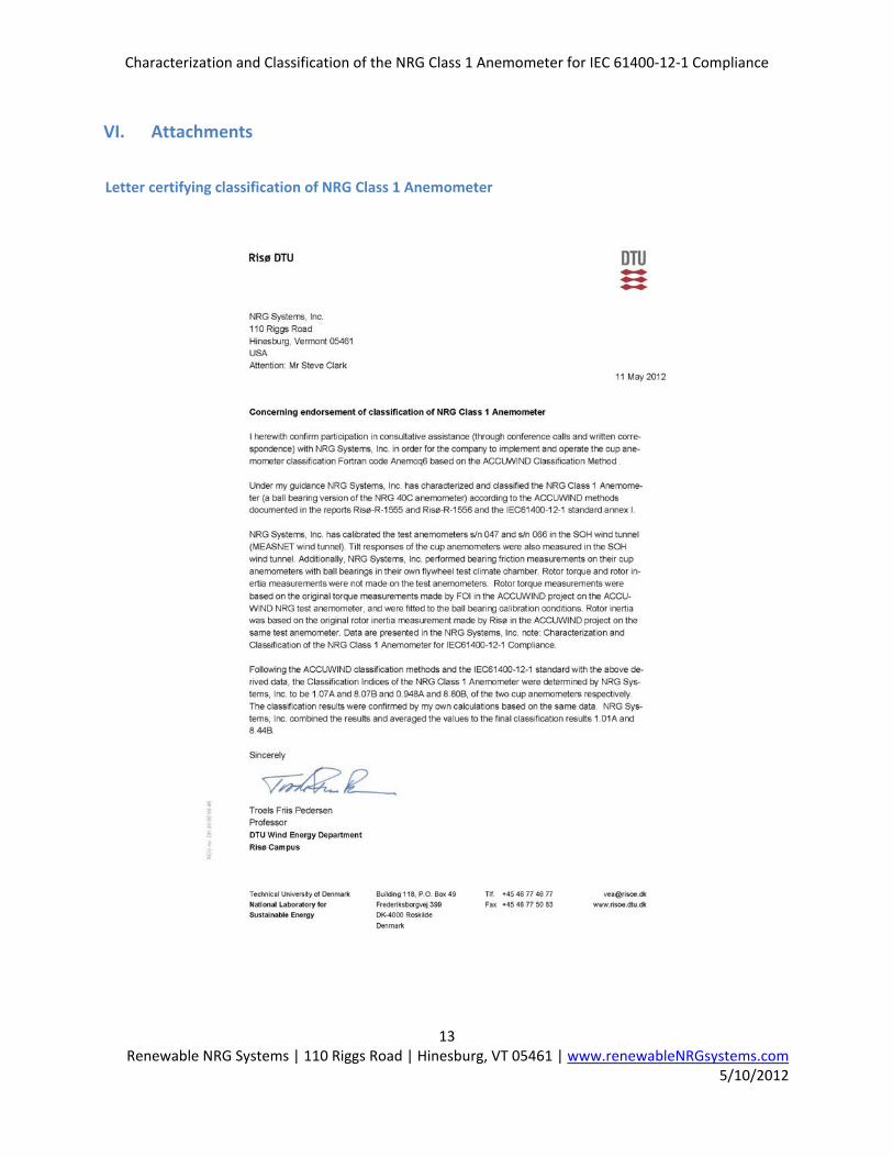
VI. Attachments
Letter certifying classification of NRG Class 1 Anemometer

Characterization and Classification of the NRG Class 1 Anemometer for IEC 61400‐12‐1 Compliance
14 Renewable NRG Systems | 110 Riggs Road | Hinesburg, VT 05461 | www.renewableNRGsystems.com
5/10/2012
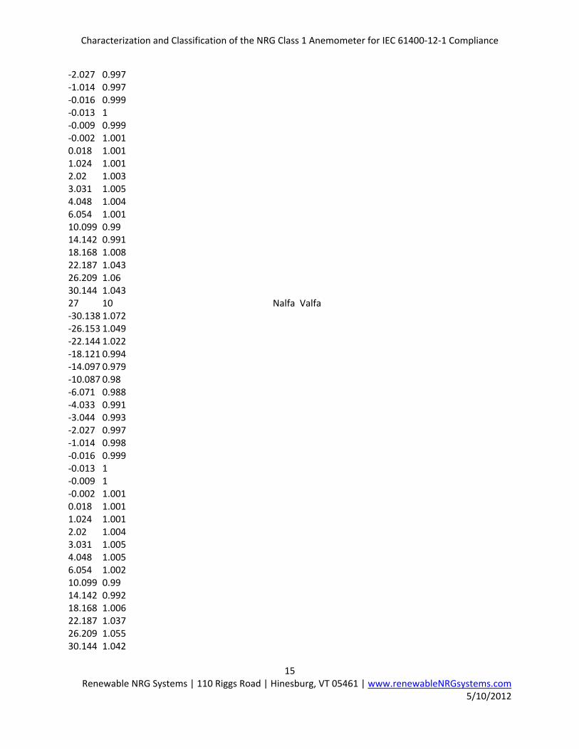
NRGBBO‐047.cup Input File NRG BBO 40 Cup anemometer name ACCUWIND 0.070 0.00200 0.000101 2 R Area I N(pulses/rev) 0.76572 0.19924 31.5 1.16 Acal Bcal (U=Acal*f+Bcal) Tcal Denscal 0.1375 Ut 2 Cup model (1 CqPol(Npol+alamQA0+pol‐coeff) 2 CqTable(Ndata+lambda ver. Cq‐coeff)
19 ‐0.0014 Ncq LamCorr (model 2) (added lambda0 value at zero torque)
0.2195846 0.4131825 0.2258573 0.383902 0.2336324 0.3334675 0.2431028 0.2781659 0.2545438 0.2032274 0.2662563 0.1249963 0.2788921 0.0342945 0.284611 0.0000000 0.2851037 ‐0.0029559 0.2919326 ‐0.0369015 0.3060246 ‐0.1173289 0.3229471 ‐0.2371572 0.343841 ‐0.3867344 0.3677941 ‐0.5398267 0.3986888 ‐0.7445405 0.4362507 ‐1.0651025 0.4839353 ‐1.3742118 0.5400939 ‐1.7541968 0.5898678 ‐2.1130812 8 Ntemp No of temperatures ‐30 0.3440E‐04 0.0191E‐04 ‐0.0001E‐04 ‐20 0.2670E‐04 0.0133E‐04 ‐0.0000E‐04 ‐10 0.2219E‐04 0.0080E‐04 ‐0.0000E‐04 0 0.1985E‐04 0.0055E‐04 ‐0.0000E‐04 10 0.1896E‐04 0.0034E‐04 ‐0.0000E‐04 20 0.1824E‐04 0.0024E‐04 ‐0.0000E‐04 30 0.1698E‐04 0.0018E‐04 ‐0.0000E‐04 40 0.1622E‐04 0.0014E‐04 ‐0.0000E‐04 27 7 SOH tilt data, Nalfa Valfa ‐30.138 1.069 ‐26.153 1.045 ‐22.144 1.019 ‐18.121 0.992 ‐14.097 0.98 ‐10.087 0.982 ‐6.071 0.989 ‐4.033 0.991 ‐3.044 0.994
Characterization and Classification of the NRG Class 1 Anemometer for IEC 61400‐12‐1 Compliance
15 Renewable NRG Systems | 110 Riggs Road | Hinesburg, VT 05461 | www.renewableNRGsystems.com
5/10/2012
‐2.027 0.997 ‐1.014 0.997 ‐0.016 0.999 ‐0.013 1 ‐0.009 0.999 ‐0.002 1.001 0.018 1.001 1.024 1.001 2.02 1.003 3.031 1.005 4.048 1.004 6.054 1.001 10.099 0.99 14.142 0.991 18.168 1.008 22.187 1.043 26.209 1.06 30.144 1.043 27 10 Nalfa Valfa ‐30.138 1.072 ‐26.153 1.049 ‐22.144 1.022 ‐18.121 0.994 ‐14.097 0.979 ‐10.087 0.98 ‐6.071 0.988 ‐4.033 0.991 ‐3.044 0.993 ‐2.027 0.997 ‐1.014 0.998 ‐0.016 0.999 ‐0.013 1 ‐0.009 1 ‐0.002 1.001 0.018 1.001 1.024 1.001 2.02 1.004 3.031 1.005 4.048 1.005 6.054 1.002 10.099 0.99 14.142 0.992 18.168 1.006 22.187 1.037 26.209 1.055 30.144 1.042
Characterization and Classification of the NRG Class 1 Anemometer for IEC 61400‐12‐1 Compliance
16 Renewable NRG Systems | 110 Riggs Road | Hinesburg, VT 05461 | www.renewableNRGsystems.com
5/10/2012
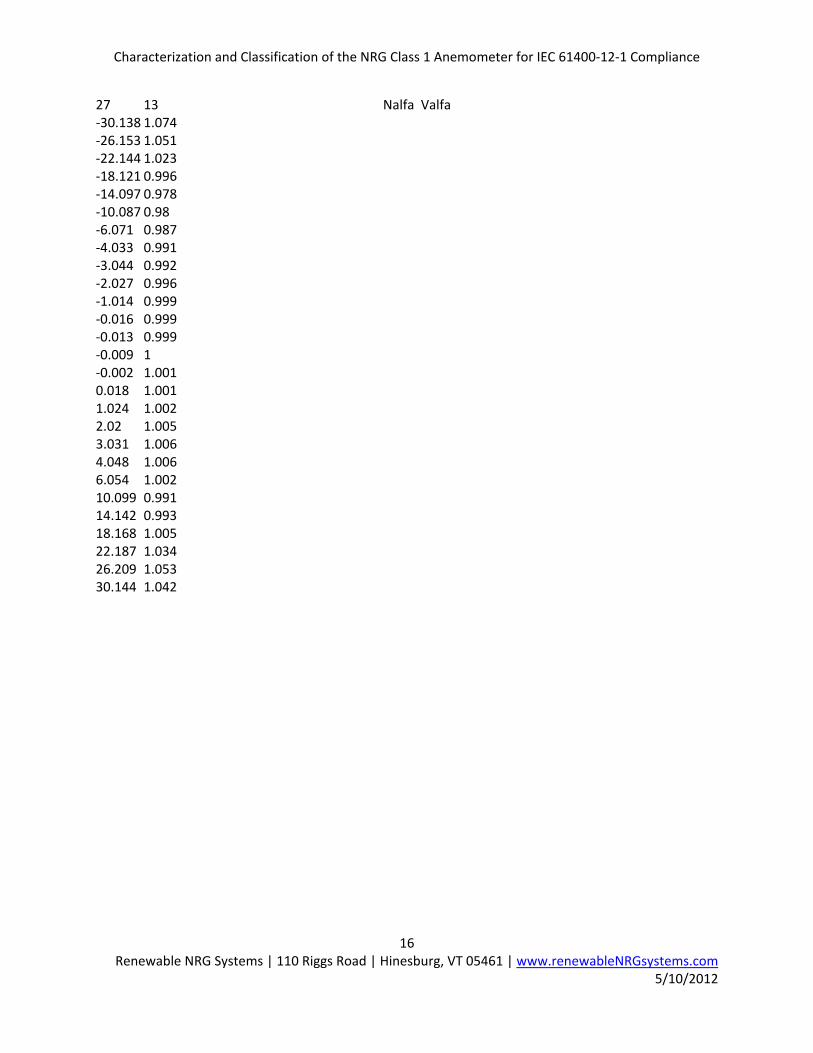
27 13 Nalfa Valfa ‐30.138 1.074 ‐26.153 1.051 ‐22.144 1.023 ‐18.121 0.996 ‐14.097 0.978 ‐10.087 0.98 ‐6.071 0.987 ‐4.033 0.991 ‐3.044 0.992 ‐2.027 0.996 ‐1.014 0.999 ‐0.016 0.999 ‐0.013 0.999 ‐0.009 1 ‐0.002 1.001 0.018 1.001 1.024 1.002 2.02 1.005 3.031 1.006 4.048 1.006 6.054 1.002 10.099 0.991 14.142 0.993 18.168 1.005 22.187 1.034 26.209 1.053 30.144 1.042

Characterization and Classification of the NRG Class 1 Anemometer for IEC 61400‐12‐1 Compliance
17 Renewable NRG Systems | 110 Riggs Road | Hinesburg, VT 05461 | www.renewableNRGsystems.com
5/10/2012
NRGBBO‐066.cup Input File
NRG BBO 40 Cup anemometer name ACCUWIND 0.070 0.00200 0.000101 2 R Area I N(pulses/rev) 0.76645 0.20439 31.7 1.16 Acal Bcal (U=Acal*f+Bcal) Tcal Denscal 0.15 Ut 2 Cup model (1 CqPol(Npol+alamQA0+pol‐coeff) 2 CqTable(Ndata+lambda ver. Cq‐coeff)
19 ‐0.001 Ncq LamCorr (model 2) (added lambda0 value at zero torque)
0.2195846 0.4131825 0.2258573 0.383902 0.2336324 0.3334675 0.2431028 0.2781659 0.2545438 0.2032274 0.2662563 0.1249963 0.2788921 0.0342945 0.284611 0.0000000 0.2851037 ‐0.0029559 0.2919326 ‐0.0369015 0.3060246 ‐0.1173289 0.3229471 ‐0.2371572 0.343841 ‐0.3867344 0.3677941 ‐0.5398267 0.3986888 ‐0.7445405 0.4362507 ‐1.0651025 0.4839353 ‐1.3742118 0.5400939 ‐1.7541968 0.5898678 ‐2.1130812 8 Ntemp No of temperatures ‐30 0.3445E‐04 0.0154E‐04 ‐0.0000E‐04 ‐20 0.3011E‐04 0.0084E‐04 ‐0.0000E‐04 ‐10 0.2637E‐04 0.0051E‐04 ‐0.0000E‐04 0 0.2400E‐04 0.0034E‐04 ‐0.0000E‐04 10 0.2219E‐04 0.0023E‐04 ‐0.0000E‐04 20 0.2081E‐04 0.0019E‐04 ‐0.0000E‐04 30 0.2000E‐04 0.0015E‐04 ‐0.0000E‐04 40 0.1919E‐04 0.0011E‐04 ‐0.0000E‐04 27 7 SOH Tilt Data Nalfa Valfa ‐30.148 1.079 ‐26.154 1.053 ‐22.13 1.023 ‐18.108 0.996 ‐14.088 0.982 ‐10.085 0.982 ‐6.071 0.991 ‐4.041 0.995 ‐3.044 0.997

Characterization and Classification of the NRG Class 1 Anemometer for IEC 61400‐12‐1 Compliance
18 Renewable NRG Systems | 110 Riggs Road | Hinesburg, VT 05461 | www.renewableNRGsystems.com
5/10/2012
‐2.032 0.998 ‐1.012 0.998 ‐0.009 1 ‐0.006 0.999 ‐0.005 1 0.002 1 0.005 1 1.02 1.002 2.018 1.003 3.013 1.004 4.031 1.004 6.059 1.001 10.09 0.99 14.133 0.994 18.169 1.014 22.166 1.054 26.176 1.073 30.125 1.06 27 10 ‐30.148 1.083 ‐26.154 1.057 ‐22.13 1.028 ‐18.108 0.998 ‐14.088 0.981 ‐10.085 0.982 ‐6.071 0.989 ‐4.041 0.994 ‐3.044 0.996 ‐2.032 0.997 ‐1.012 0.998 ‐0.009 1 ‐0.006 1 ‐0.005 1 0.002 0.999 0.005 1.001 1.02 1.002 2.018 1.004 3.013 1.005 4.031 1.005 6.059 1.002 10.09 0.992 14.133 0.993 18.169 1.011 22.166 1.049 26.176 1.071 30.125 1.067

Characterization and Classification of the NRG Class 1 Anemometer for IEC 61400‐12‐1 Compliance
19 Renewable NRG Systems | 110 Riggs Road | Hinesburg, VT 05461 | www.renewableNRGsystems.com
5/10/2012
27 13 ‐30.148 1.085 ‐26.154 1.058 ‐22.13 1.03 ‐18.108 0.999 ‐14.088 0.98 ‐10.085 0.981 ‐6.071 0.987 ‐4.041 0.993 ‐3.044 0.995 ‐2.032 0.996 ‐1.012 0.998 ‐0.009 1 ‐0.006 1 ‐0.005 1.001 0.002 0.999 0.005 1.001 1.02 1.003 2.018 1.004 3.013 1.005 4.031 1.005 6.059 1.003 10.09 0.992 14.133 0.993 18.169 1.009 22.166 1.047 26.176 1.07 30.125 1.071