ZERMEG II - Zero emission retrofitting method for existing galvanising plants
� To demonstrate the use of the SSS method on a real vehicle body
� To ensure the structure has satisfactory load-path continuitypath continuity
� To determine load in beams, panels, and subassemblies
� The SSS method is most effectively applied during the conceptual state, and also used to help resolve issues on existing structure.
� The base existing platform will need to be � The base existing platform will need to be idealized.
� The baseline load paths for both bending and torsion load cases are determined.
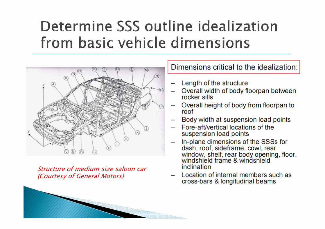
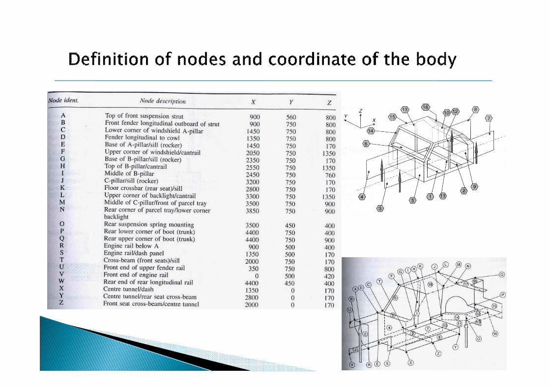
Structure of medium size saloon car (Courtesy of General Motors)
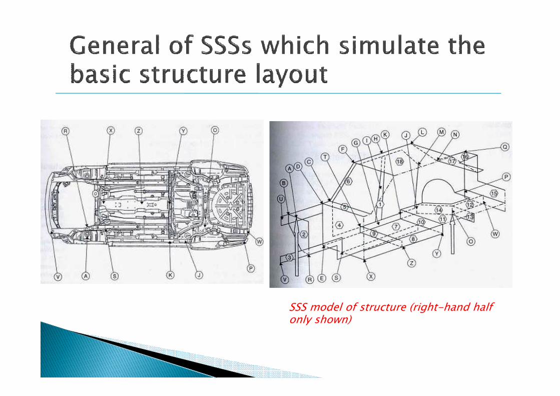
SSS model of structure (right-hand half only shown)

� The side-frame (1)
� The front suspension tower (2)
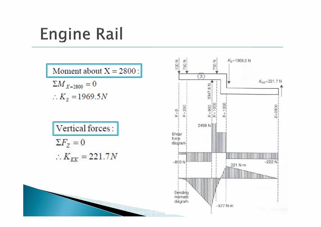
� The engine rail-Z shape (3)
� The dash (4)
� The cowl (5)
� The windscreen frame (6)
� The centre floor (7)
� The centre longitudinal beam (8)� The centre longitudinal beam (8)
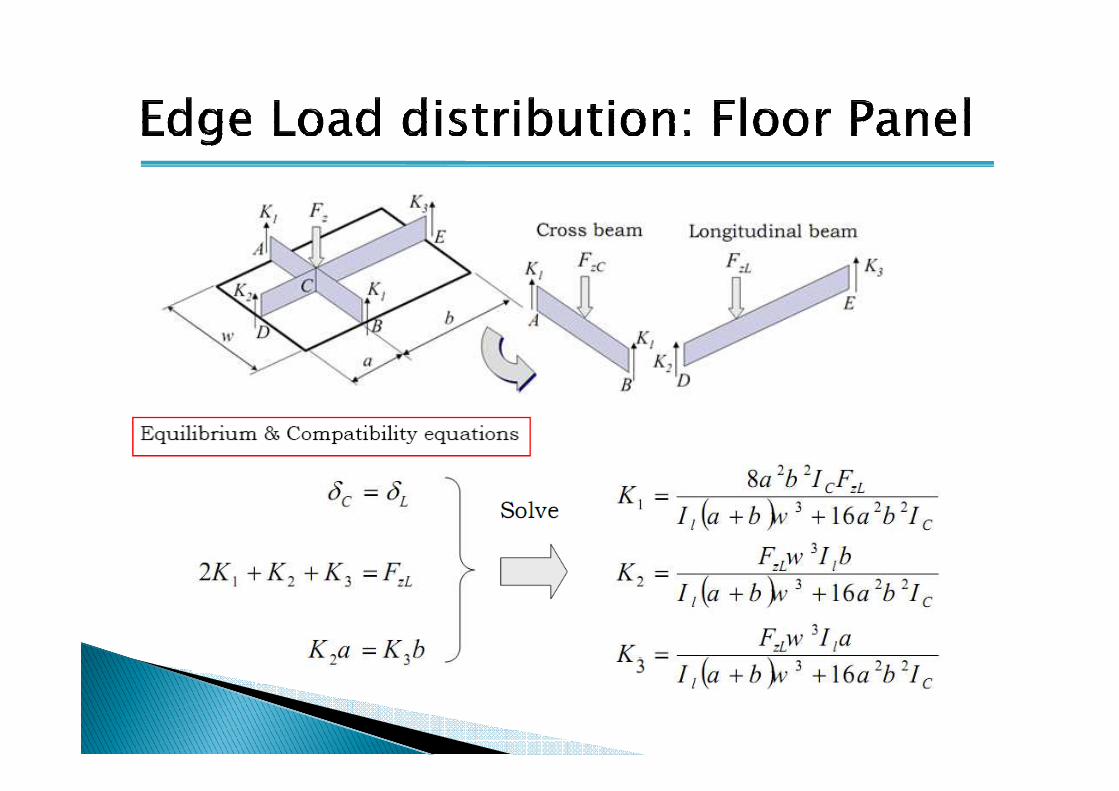
� The floor cross-beams (9), (10)
� The rear floor (11)
� The rear longitudinal (12)
� The rear cross-beam (13)
� The angled beam (14)
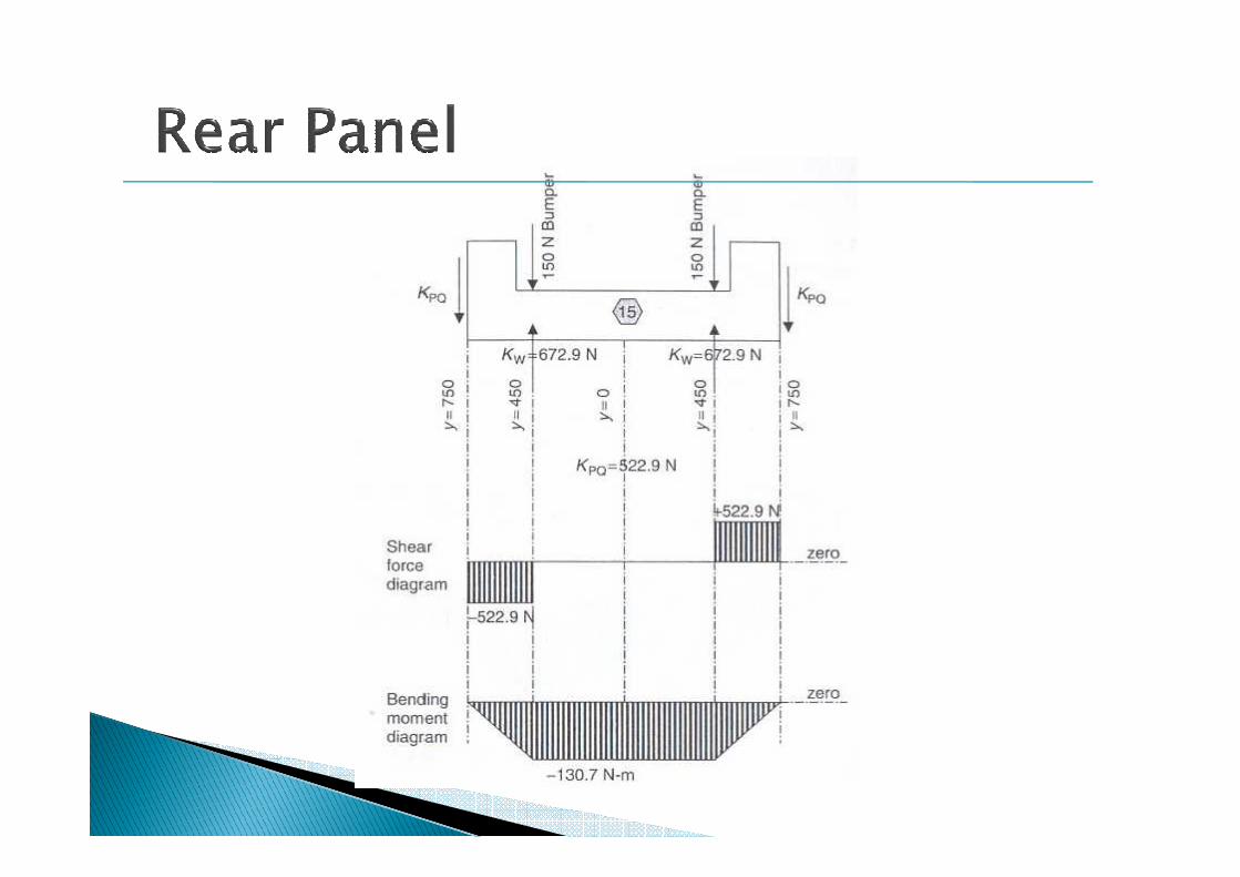
� The rear panel (15)
� The boot top (16)
� The backlight frame (17)
� The roof (18)
A total of 18 SSSs for only half model

Typical load distribution for a medium size passenger carTypical load distribution for a medium size passenger carTypical load distribution for a medium size passenger carTypical load distribution for a medium size passenger car
“Using the factor 10 simplifies the arithmetic”(9.81 m/s2)
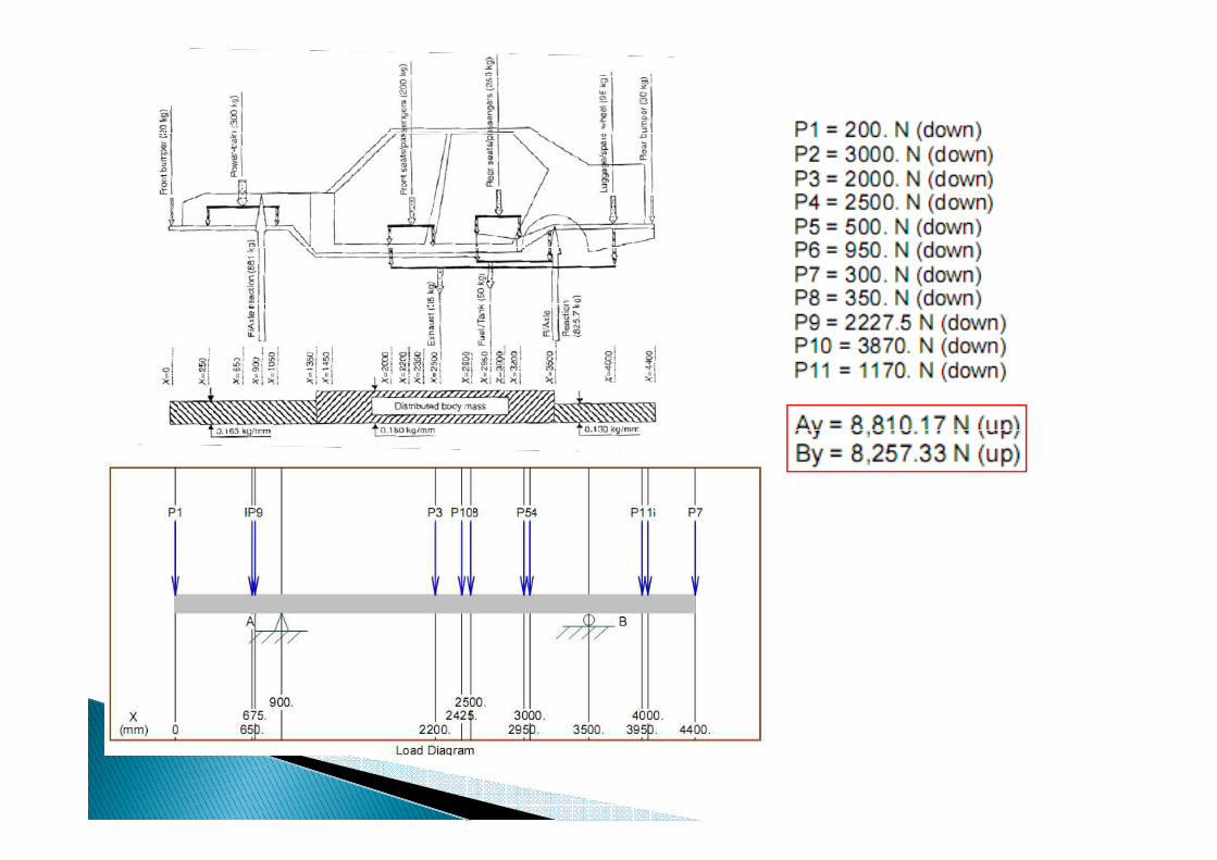

SF and BM diagramSF and BM diagram Slope and DeflectionSlope and Deflection
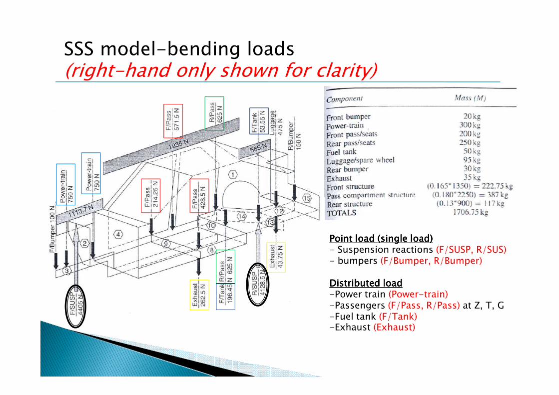
SSS model-bending loads (right-hand only shown for clarity)
Point load (single load)Point load (single load)Point load (single load)Point load (single load)- Suspension reactions (F/SUSP, R/SUS)- bumpers (F/Bumper, R/Bumper)
Distributed loadDistributed loadDistributed loadDistributed load-Power train (Power-train) -Passengers (F/Pass, R/Pass) at Z, T, G-Fuel tank (F/Tank)-Exhaust (Exhaust)
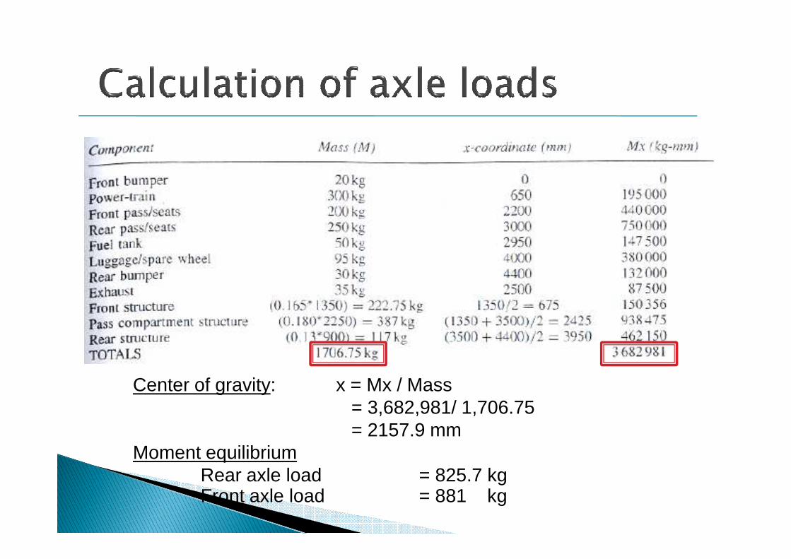
Center of gravity: x = Mx / Mass= 3,682,981/ 1,706.75= 2157.9 mm
Moment equilibriumRear axle load = 825.7 kgFront axle load = 881 kg


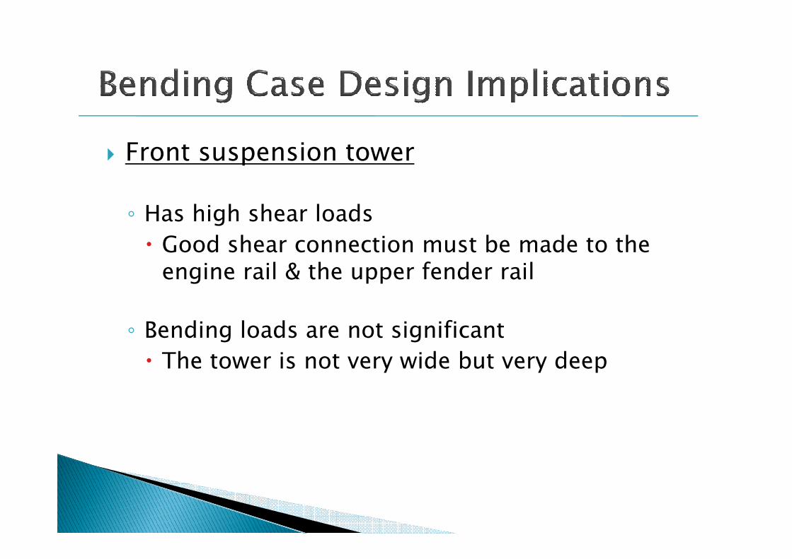
� Front suspension tower
◦ Has high shear loads
� Good shear connection must be made to the engine rail & the upper fender railengine rail & the upper fender rail
◦ Bending loads are not significant
� The tower is not very wide but very deep

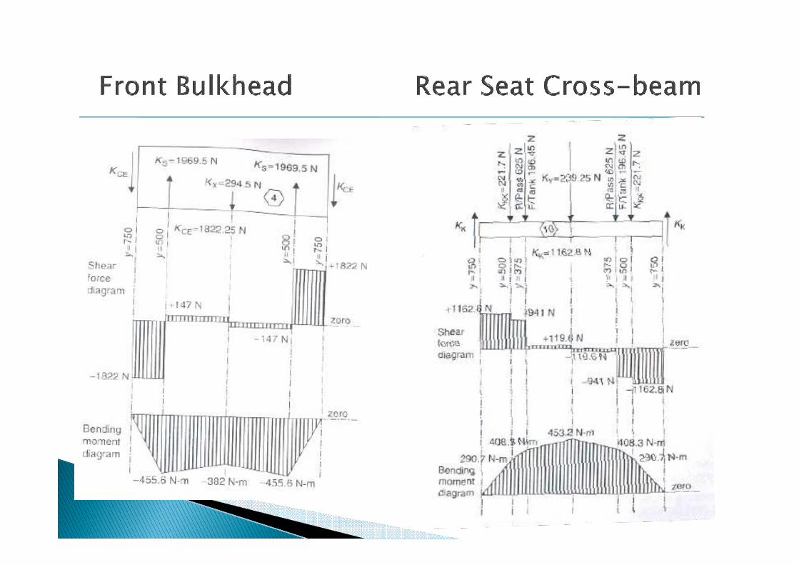
� Front Bulkhead
◦ Bending moment on the dash panel is a hogging moment
� It is not a severe condition as the dash panel is very � It is not a severe condition as the dash panel is very deep
◦ Side shear force is significant
� May indicate the need of stiffeners (swaging)
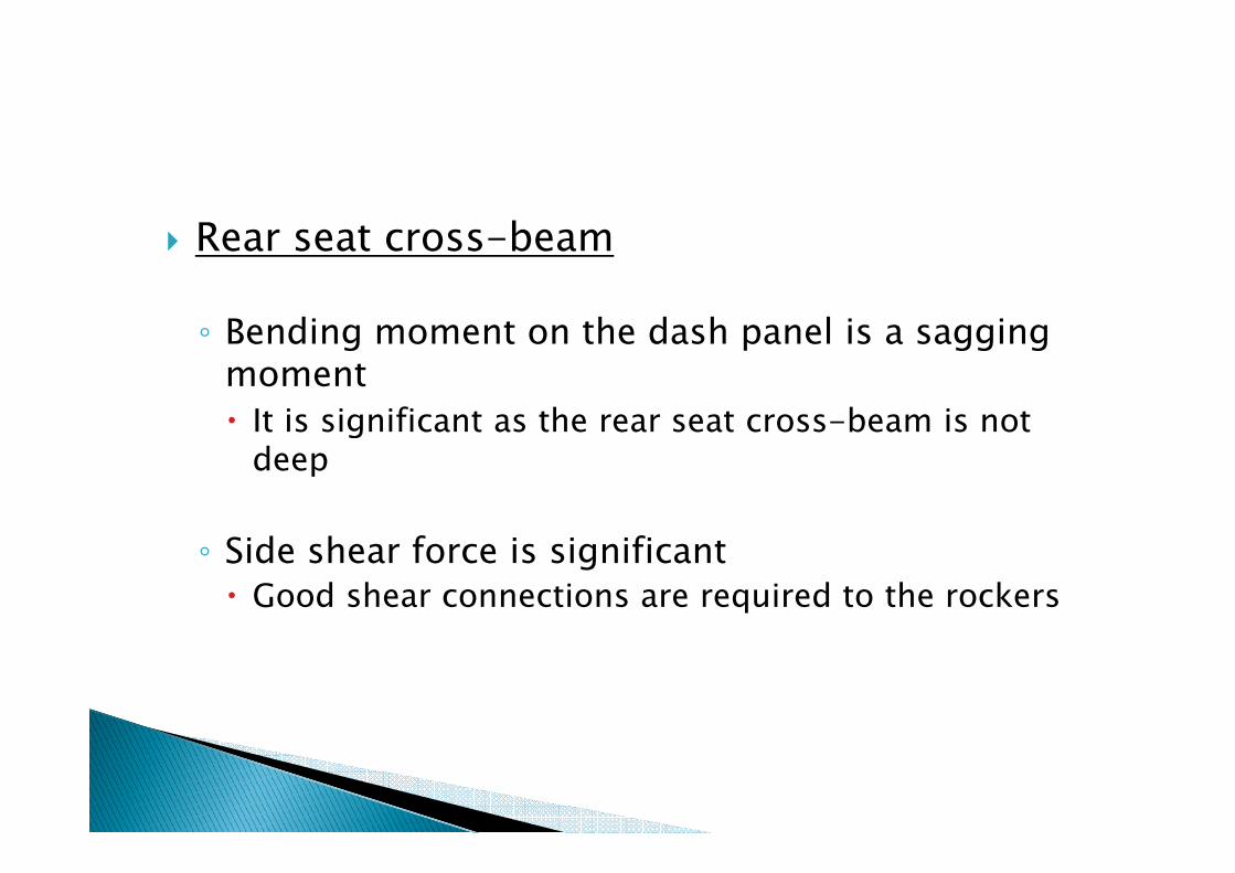
� Rear seat cross-beam
◦ Bending moment on the dash panel is a sagging moment
� It is significant as the rear seat cross-beam is not � It is significant as the rear seat cross-beam is not deep
◦ Side shear force is significant
� Good shear connections are required to the rockers
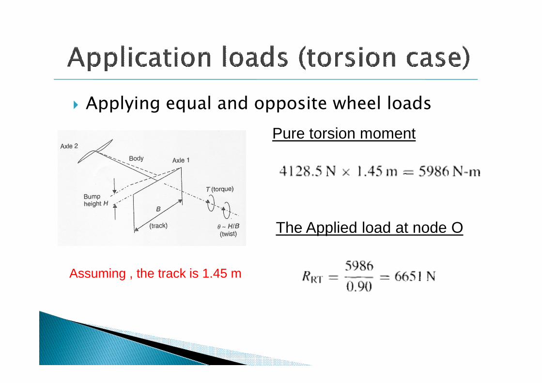
� Applying equal and opposite wheel loads
Pure torsion moment
Assuming , the track is 1.45 m
The Applied load at node O
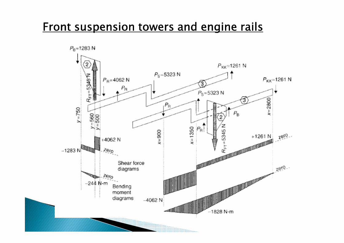
Front suspension towers and engine railsFront suspension towers and engine railsFront suspension towers and engine railsFront suspension towers and engine rails
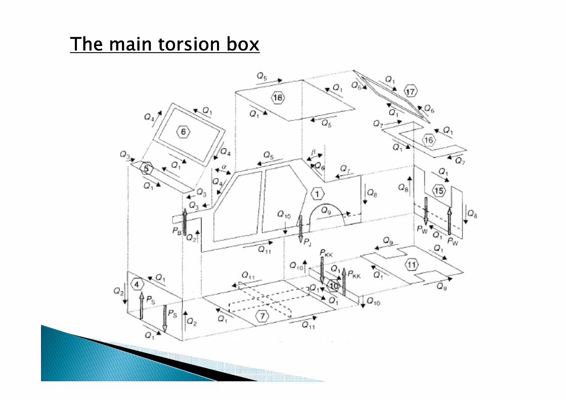
The main torsion boxThe main torsion boxThe main torsion boxThe main torsion box
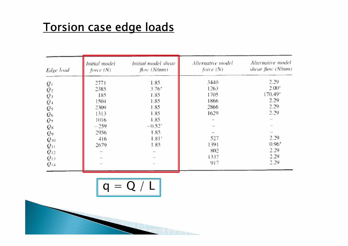
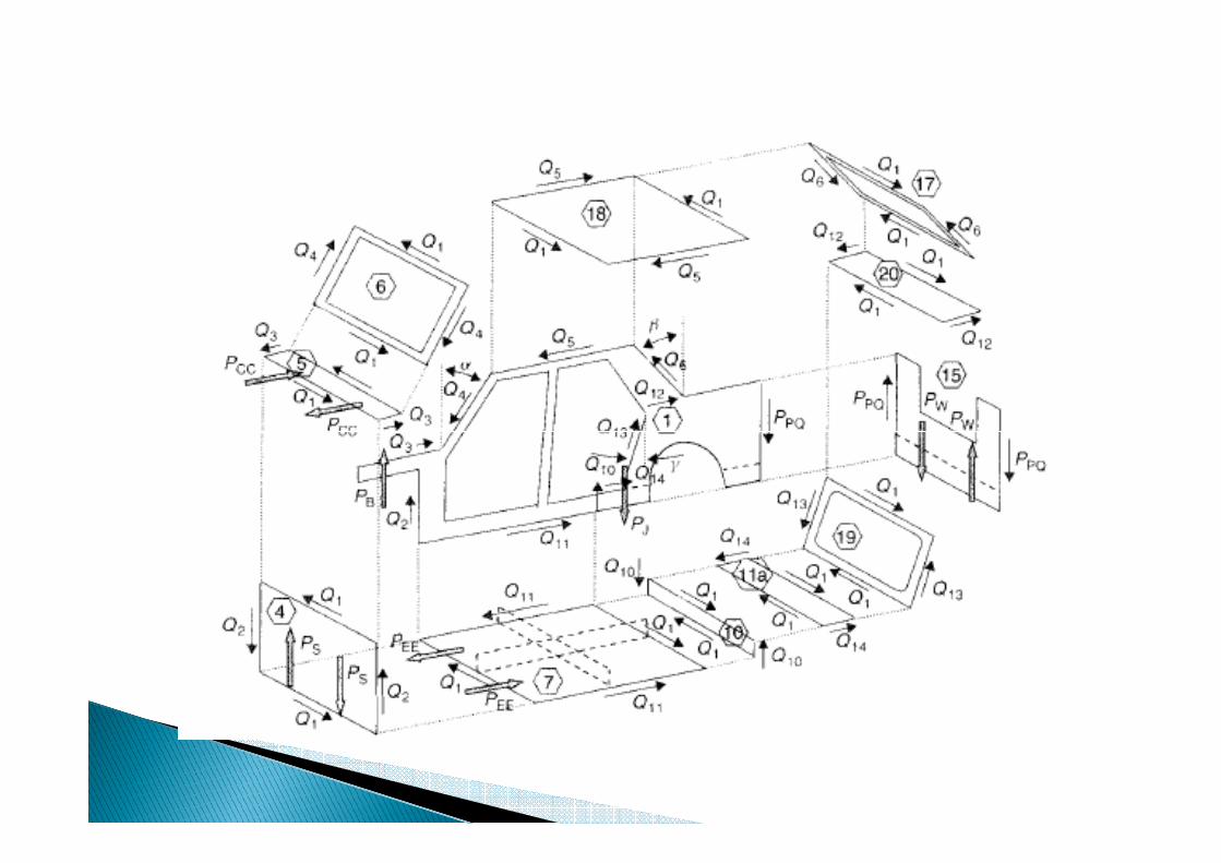
Torsion case edge loadsTorsion case edge loadsTorsion case edge loadsTorsion case edge loads
q = Q / L
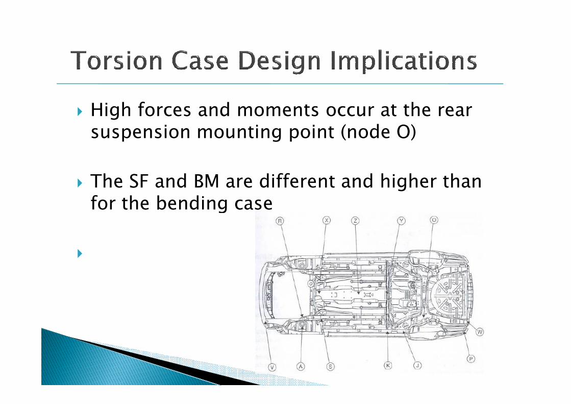
� High forces and moments occur at the rear suspension mounting point (node O)
� The SF and BM are different and higher than for the bending casefor the bending case
�
� The loading on engine rail shows much higher SF and BM than bending case
� On the main torsion box, it shows the importance of maintaining a continuous shear importance of maintaining a continuous shear path.
� The windscreen and backlight frames must have adequate section stiffness and good corner joints. (max bending)


� Require a good shear connection between the inner wing and dash panel.
� Require a stiffening member between the top of the suspension tower and the cowl.of the suspension tower and the cowl.
� The cowl carries a significant BM including the SF transferred between the dash panel and the windshield frame.

� At the real panel acts as beam is not require to carry shear between the floor and boot top frame.
� Similarly, the boot top frame does not � Similarly, the boot top frame does not required carry shear between the rear panel and the backlight frame.
� The alternative model has shear flow values higher than in the original model because of the reduced area main torsion box.