CHAPTER 7 TRAFFIC SIGNAL DESIGN – OPERATIONS AND …...traffic signal controller to recall the...
82
TDOT TRAFFIC DESIGN MANUAL DECEMBER 2016 7 - 1 CHAPTER 7 TRAFFIC SIGNAL DESIGN – OPERATIONS AND COORDINATION 7.1 Traffic Signal Operation Basic Concepts The following are basic concepts in traffic signal operation: 7.1.1 Traffic Signal Movements Traffic signal movements refer to the actions of users at a signalized intersection. Typical movements include vehicles turning left, turning right or traveling through the intersection, and pedestrian crossings. In a four-legged intersection it is possible to have twelve vehicle movements and four two-way pedestrian movements. The HCM assigns numbers to each of these movements, as shown on Figure 7.1, with the major street on the East–West orientation. Figure 7.2 shows a typical movement numbering with the major street on the North–South orientation. 7.1.2 Traffic Signal Phases A phase is a timing process, within the signal controller, that facilitates serving one or more movements at the same time (for one or more modes of users). Phase numbers must be assigned to the movements at a signalized intersection in order to begin selecting signal timing values. Even phases are typically associated with vehicular through movements and odd phases are typically associated with vehicular left-turn movements. Pedestrian phases are typically set up to run concurrently with the even-numbered vehicular phases and are generally assigned the same phase number as the adjacent parallel vehicular phases. A four-legged intersection with protected left-turn movements will generally follow the phase numbering as shown in Figures 7.1 and 7.2. This standard NEMA phase numbering system combines the right-turn movements with the through movements into single phases. Figure 7.3 illustrates the typical movement and phase numbering (4-phase or 8-phase) used at an intersection with permitted left-turn movements where all of the movements on an approach are assigned to one phase. It is common practice to maintain a consistent phase- numbering scheme within a specific jurisdiction.
Transcript of CHAPTER 7 TRAFFIC SIGNAL DESIGN – OPERATIONS AND …...traffic signal controller to recall the...

TDOT TRAFFIC DESIGN MANUAL DECEMBER 2016
7 - 1
CHAPTER 7
TRAFFIC SIGNAL DESIGN – OPERATIONS AND COORDINATION
7.1 Traffic Signal Operation Basic Concepts The following are basic concepts in traffic signal operation:
7.1.1 Traffic Signal Movements Traffic signal movements refer to the actions of users at a signalized intersection. Typical movements include vehicles turning left, turning right or traveling through the intersection, and pedestrian crossings. In a four-legged intersection it is possible to have twelve vehicle movements and four two-way pedestrian movements. The HCM assigns numbers to each of these movements, as shown on Figure 7.1, with the major street on the East–West orientation. Figure 7.2 shows a typical movement numbering with the major street on the North–South orientation.
7.1.2 Traffic Signal Phases A phase is a timing process, within the signal controller, that facilitates serving one or more movements at the same time (for one or more modes of users). Phase numbers must be assigned to the movements at a signalized intersection in order to begin selecting signal timing values. Even phases are typically associated with vehicular through movements and odd phases are typically associated with vehicular left-turn movements. Pedestrian phases are typically set up to run concurrently with the even-numbered vehicular phases and are generally assigned the same phase number as the adjacent parallel vehicular phases. A four-legged intersection with protected left-turn movements will generally follow the phase numbering as shown in Figures 7.1 and 7.2. This standard NEMA phase numbering system combines the right-turn movements with the through movements into single phases. Figure 7.3 illustrates the typical movement and phase numbering (4-phase or 8-phase) used at an intersection with permitted left-turn movements where all of the movements on an approach are assigned to one phase. It is common practice to maintain a consistent phase-numbering scheme within a specific jurisdiction.

TDOT TRAFFIC DESIGN MANUAL DECEMBER 2016
7 - 2
Figure 7.1 – Movement and Phase Numbering (East-West as Major Street) Source: Adapted from Traffic Signal Timing Manual

TDOT TRAFFIC DESIGN MANUAL DECEMBER 2016
7 - 3
Figure 7.2 – Movement and Phase Numbering (North-South as Major Street) Source: Adapted from Traffic Signal Timing Manual

TDOT TRAFFIC DESIGN MANUAL DECEMBER 2016
7 - 4
Figure 7.3 – Movement and Phase Numbering (Permissive Left-Turns) Source: Adapted from Traffic Signal Timing Manual

TDOT TRAFFIC DESIGN MANUAL DECEMBER 2016
7 - 5
7.1.3 Ring-and-Barrier Diagrams Traffic signal phases and their sequence are represented graphically by a ring-and-barrier diagram composed of: Rings: Each ring identifies phases that may operate one after another, but
never simultaneously. At any moment there may be only one phase active per ring. Dual ring operations allow concurrent (non-conflicting) phases in separate rings to operate at the same time.
Barriers: In dual ring operation, a barrier is the point at which the phases in both rings must end simultaneously. Barriers typically separate major and minor street phases.
Figure 7.4 provides an example of a standard NEMA eight-phase, dual ring-and-barrier diagram, with protected leading left-turns (See Section 7.3) on all approaches. A table of active and concurrent phases and a standard NEMA eight-phase actuated controller phase sequence are also shown.
7.2 Traffic Signal Modes of Operation An intersection may be controlled independently (isolated operation) or have the ability to synchronize to multiple intersections in a coordinated operation. Isolated and coordinated intersections can operate either in pre-timed (fixed) or actuated mode, where detectors will monitor traffic demand. Furthermore, actuated operation can be characterized as fully-actuated or semi-actuated, depending on the number of traffic movements that are being detected (See Section 7.2.2). Advanced types of operation include volume density, traffic responsive, and adaptive control. Finally, signalized intersections may also operate under special conditions like preemption or priority, or they may be set up to operate in the flashing mode. The selected mode of operation on a signalized intersection will determine its safety and efficiency. The following paragraphs will briefly describe each mode of operation and additional detailed information will be further explored in subsequent sections.
7.2.1 Pre-timed (Fixed Time) Operation During pre-timed operation, the total green time allocated to a phase will always have a preset time, regardless of demand. For each specific TOD plan the phase sequence is also fixed and phases cannot be skipped. Therefore, a complete sequence of signal indications (i.e. cycle) will be displayed every time (i.e. fixed cycle length). Figure 7.5 illustrates pre-timed operation. Advantages: Ideally suited to coordination of closely spaced intersections
with consistent daily traffic volumes and patterns, since both the start and end of green phases are predictable. Such conditions are often found in CBD or downtown grid areas. Also, pre-timed operation does not require detection, thus reducing maintenance needs.
Disadvantages: Inability to adjust to fluctuations in traffic demand potentially generating excessive delays to users of the intersection.

TDOT TRAFFIC DESIGN MANUAL DECEMBER 2016
7 - 6
Figure 7.4 – Standard NEMA Dual Ring-and-Barrier Diagram Source: Traffic Signal Timing Manual

TDOT TRAFFIC DESIGN MANUAL DECEMBER 2016
7 - 7
Figure 7.5 – Pre-timed and Actuated Operation Source: Traffic Signal Timing Manual

TDOT TRAFFIC DESIGN MANUAL DECEMBER 2016
7 - 8
7.2.2 Actuated Operation During actuated operation, detection actuations will determine phases to be called as well as phase extension. The duration of each phase is determined by detector input and corresponding controller parameters. For each specific TOD plan, the phase sequence is fixed but phases can be skipped due to traffic demand being monitored by detection. Therefore, when not coordinated, actuated operation may not always display a complete sequence of signal indications (i.e. cycle) leading to a variable cycle length. Advantages: Ability to adjust to fluctuations in traffic demand potentially
reducing delay to users of the intersection. Disadvantages: Higher equipment cost and more extensive maintenance
needs due to the need of detection. Actuated operation can be characterized as fully-actuated or semi-actuated, depending on the number of traffic movements provided with detection. Figure 7.5 illustrates both actuated operations. Fully-Actuated Operation: In fully-actuated operation, detection is
provided to all the phases at an intersection. This type of operation is ideally suited to isolated intersections where less predictable traffic demand exists on all approaches.
Semi-Actuated Operation: In semi-actuated operation, detection is provided only to the phases controlling the minor movements at an intersection. The major movements (typically major road through movements) are operated non-actuated. Locations with sporadic or low volumes on the side streets are best suited for semi-actuated operation. This type of operation is common under coordinated systems where the coordinated phases are guaranteed service every cycle and minor movements are serviced only when demand exists. It is necessary to note that semi-actuated operation under a non-coordinated system (e.g.: free operation during early morning hours) will require the programming of the traffic signal controller to recall the non-actuated phases.
7.2.3 Coordinated Operation During coordinated operation, multiple signalized intersections are synchronized to enhance the progression of vehicles on one or more directional movements in a system. Pre-timed coordination provides better progression from a driver standpoint, but higher delay is also experienced. Actuated coordination is more efficient, but progression is not consistently achieved. Section 7.6 explores coordination design parameters and coordination challenges in detail.

TDOT TRAFFIC DESIGN MANUAL DECEMBER 2016
7 - 9
7.2.4 Volume-Density Operation Volume-density (also known as density timing) is an enhanced actuated operation where actuated controller parameters (minimum green and passage time) are automatically adjusted to improve intersection efficiency according to varying traffic demand. Section 7.8.1 explores volume-density design parameters in detail.
7.2.5 Traffic Responsive Operation Traffic responsive is an advanced mode of operation that uses data from traffic detectors, rather than time of day, to automatically select the timing plan best suited to current traffic conditions. A predetermined library of timing plans is necessary. Section 7.8.2 explores traffic responsive design parameters in detail.
7.2.6 Adaptive Signal Control Technology Operation Adaptive traffic signal control is an advanced mode of operation where vehicular traffic is monitored by upstream and/or downstream detection and an algorithm is used to automatically implement timing adjustments to accommodate fluctuations in traffic demand. Section 7.8.3 explores adaptive signal control technology design parameters in detail.
7.2.7 Traffic Signal Preemption Traffic signal preemption is a type of preferential treatment based on the immediate transfer of normal operation of a traffic control signal to a special control mode of operation to accommodate the most important classes of vehicles during their approach to and passage of the intersection (e.g. railroad, LRT, emergency vehicle, etc.). Preemption may interrupt signal coordination. A request for preemption shall be serviced by the traffic signal equipment. Section 7.10 explores traffic signal preemption design parameters in detail.
7.2.8 Traffic Signal Priority Traffic signal priority is a type of preferential treatment based on an operational strategy communicated between vehicles and traffic signals to alter the signal timing for the benefit or priority of those vehicles (mostly transit and heavy trucks). Coordination will not be affected by priority. Service is not guaranteed during a priority request. Section 7.9 explores traffic signal priority design parameters in detail.
TDOT TRAFFIC DESIGN MANUAL DECEMBER 2016
7 - 10
7.2.9 Flashing Mode Operation A signalized intersection is operating under the flashing mode when at least one traffic signal indication in each vehicular signal face of a highway traffic signal is turned on and off repetitively. Flashing mode operation can be characterized by planned or unplanned circumstances: Planned Operation: Based on engineering study or engineering
judgment, traffic control signals may be operated in the flashing mode on a scheduled basis during one or more periods of the day (night time, off-peak) rather than operated continuously in the steady (stop-and-go) mode.
Unplanned Operation: A signalized intersection will be forced into the flashing mode when a malfunction is detected in the traffic signal equipment or it may be forced into the flashing mode when it is undergoing maintenance. A signalized intersection may also be operating under flashing mode during preemption. Additional information is provided in Section 7.11.
7.3 Traffic Signal Phasing The determination of the traffic signal phasing and its sequence is an important step in traffic signal design. The design should incorporate the fewest number of signal phases that can safely and efficiently move traffic. Additional phases will increase the total start-up lost time experienced at the beginning of each green interval as well as the number of signal clearance intervals (yellow change plus red clearance) per cycle, leading to larger cycle lengths and higher intersection delay. Special consideration is necessary for the selection of left-turn treatments. There are four options for the left-turn phasing at an intersection: permissive only, protected only, protected/permissive or the left-turn movement can be prohibited. When protected left-turn phasing is used, it is also necessary to select its sequence relative to the complimentary through movement: leading left-turns, lagging left-turns, a combination of the two sequences (lead-lag left-turns), or split phasing. Additional consideration is needed on the selection for right-turn treatments. For example, the use of overlaps and the use of RTOR will influence overall intersection operation.
7.3.1 Need for Left-Turn Phasing The primary factors to consider in the need for protection are the left-turn volume and the degree of difficulty in executing the left-turn through the opposing traffic. The designer should be aware that left-turn phases can sometimes significantly reduce the efficiency of an intersection. Left-turn phasing should be considered on an approach with a peak hour left-turn volume of at least 100 vehicles and a capacity analysis showing that the overall operations are improved by the addition of the left-turn phase. In addition, the following guidelines may be used when considering the addition of separate left-turn phasing at either a new or existing signalized intersection. The following warrants may be used in the analysis of the need for the installation of separate left-turn phases.
TDOT TRAFFIC DESIGN MANUAL DECEMBER 2016
7 - 11
Left-Turn Volume Warrant: Left-turn phasing may be considered based on a cross-product threshold as defined by the product of the left-turning peak hour volume multiplied by the peak hour volume of opposing traffic (opposing traffic includes both opposing through and opposing right-turning traffic volumes) during the same peak hour. Left-turn phasing should be considered on any approach that meets the following product thresholds:
o One Opposing Lane – 50,000 o Two Opposing Lanes – 90,000 o Three Opposing Lanes – 110,000
Left-Turn Delay Warrant: Left-turn phasing may be considered if the left-turn delay is greater than or equal to two vehicle hours on the left-turn approach during the peak hour. Also, a minimum left-turn volume of two vehicles per cycle should exist with the average delay per vehicle being no less than 35 seconds.
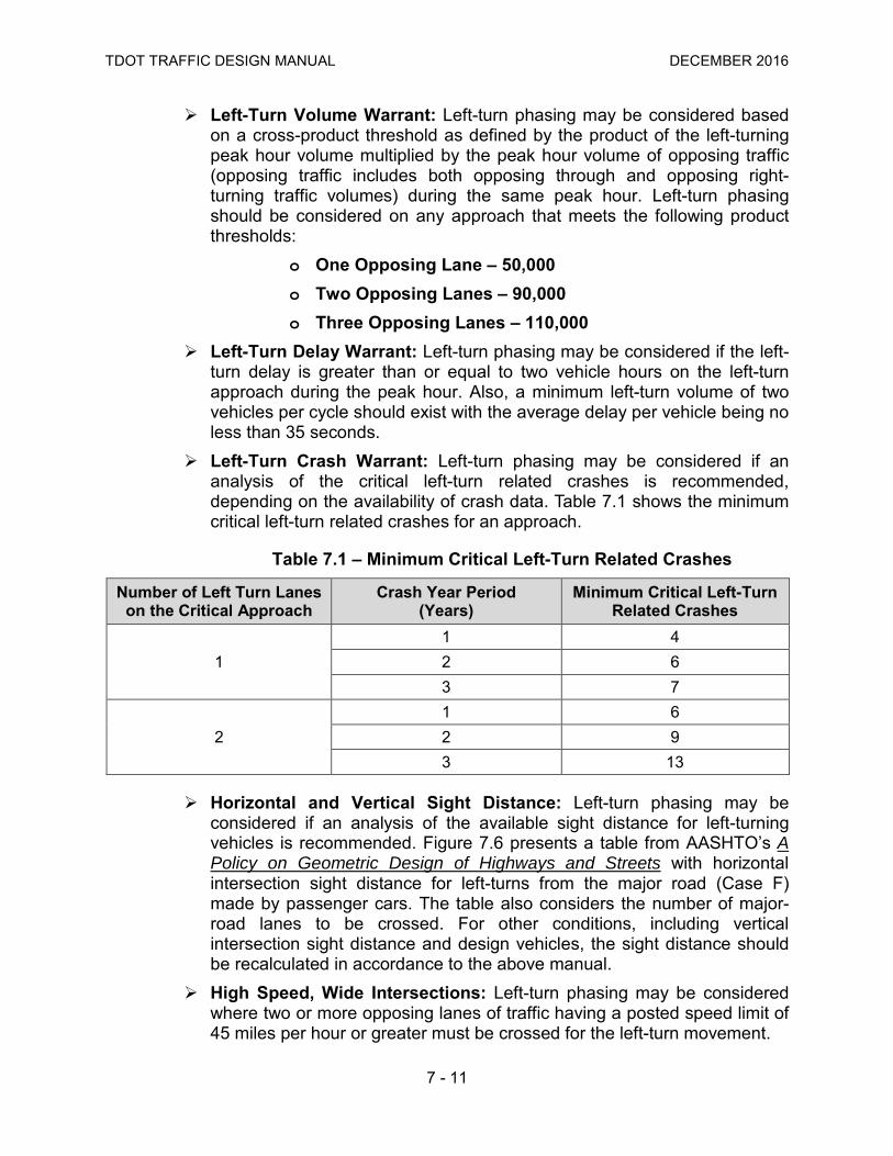
Left-Turn Crash Warrant: Left-turn phasing may be considered if an analysis of the critical left-turn related crashes is recommended, depending on the availability of crash data. Table 7.1 shows the minimum critical left-turn related crashes for an approach.
Table 7.1 – Minimum Critical Left-Turn Related Crashes
Horizontal and Vertical Sight Distance: Left-turn phasing may be considered if an analysis of the available sight distance for left-turning vehicles is recommended. Figure 7.6 presents a table from AASHTO’s A Policy on Geometric Design of Highways and Streets with horizontal intersection sight distance for left-turns from the major road (Case F) made by passenger cars. The table also considers the number of major-road lanes to be crossed. For other conditions, including vertical intersection sight distance and design vehicles, the sight distance should be recalculated in accordance to the above manual.
High Speed, Wide Intersections: Left-turn phasing may be considered where two or more opposing lanes of traffic having a posted speed limit of 45 miles per hour or greater must be crossed for the left-turn movement.
Number of Left Turn Lanes on the Critical Approach
Crash Year Period (Years)
Minimum Critical Left-Turn Related Crashes
1 1 4 2 6 3 7
2 1 6 2 9 3 13

TDOT TRAFFIC DESIGN MANUAL DECEMBER 2016
7 - 12
Offset Left-Turn Lanes: Left-turn phasing may be considered to improve sight distance and safety for left-turning vehicles. At signalized intersections, the use of offset left-turn lanes is preferred where feasible. Sight distance for left-turning vehicles ranges from a negative offset (Figure 7.7a), to being aligned with no offset (Figure 7.7b), and to a positive offset (Figure 7.7c).
Figure 7.6 – Horizontal Intersection Sight Distance for Left-Turns Source: AASHTO’s A Policy on Geometric Design of Highways and Streets

TDOT TRAFFIC DESIGN MANUAL DECEMBER 2016
7 - 13
Figure 7.7 – Offset Left-Turn Lanes
7.3.2 Types of Left-Turn Phasing Figure 7.8 illustrates the typical ring-and-barrier diagram arrangement for different types of left-turn phasing. Permissive Only Left-Turn Phasing: This phase is served concurrently
with the adjacent through movement, and requires left-turning vehicles to yield to conflicting vehicle and pedestrian movements.
• Advantages: Reduced intersection delay and efficient green allocation.
• Disadvantages: Requires users to choose acceptable gaps in traffic and, left-turn yellow trap (See Section 7.3.4) can occur if opposing movement is a lagging left-turn.
• Signal Display: Circular green or flashing left-turn yellow arrow (See Section 7.3.5).
Protected Only Left-Turn Phasing: This phase gives left-turning vehicles the right-of-way without any conflicting movements.
• Advantages: Reduced delay for left-turning vehicles and because users always receive exclusive right-of-way, gaps in traffic do not need to be identified; higher degree of safety for left-turning vehicles.
• Disadvantages: Increased intersection delay.
• Signal Display: Green arrow.

TDOT TRAFFIC DESIGN MANUAL DECEMBER 2016
7 - 14
Figure 7.8 – Ring-and-Barrier Diagram and Left-Turn Phasing Source: Traffic Signal Timing Manual

TDOT TRAFFIC DESIGN MANUAL DECEMBER 2016
7 - 15
Protected/Permissive Left-Turn Phasing: Left-turning vehicles receive exclusive right-of-way, but can also make permissive left-turn movements during the complementary through movement green indication, when yielding to conflicting vehicle and pedestrian movements is required.
• Advantages: Compromise between safety of protected left-turn phase and efficiency of permissive left-turn phase with no significant increase in delay for other movements.
• Disadvantages: Left-turn yellow trap (see Section 7.3.4) can occur if opposing movement is a lagging left-turn.
• Signal Display: Green arrow followed or preceded by circular green or flashing left-turn yellow arrow (see Section 7.3.5).
Prohibited Left-Turn Phasing: Implemented to maintain mobility at an intersection, particularly during times of day when gaps are unavailable and operation of permissive left-turn phasing may be unsafe.
• Advantages: Reduced conflicts at intersection.
• Disadvantages: Users must find alternative routes.
• Signal Display: A No Left-Turn sign (R3-2) is necessary and should be supplemented with time and day restrictions, if applicable.
Left-Turn Phasing for Inadequate Geometry of the Intersection: Two operational strategies can be applied at intersections where there is inadequate room for opposing left-turn movements to move simultaneously without a conflict:
• The use of split phasing left-turn sequence (See Section 7.3.4) that requires the use of protected only left-turn phasing on both approaches; or
• The use of lead-lag left-turn phasing sequence (See Section 7.3.4) that allows the use of protected only left-turn phasing on both approaches or the use of protected-only left-turn phasing for the leading left-turn movement while the lagging left-turn movement can operate as protected/permissive left-turn phasing.
Lack of Exclusive Left-Turn Lane: Protected only left-turn phasing shall not be used at intersections where there is no exclusive left-turn lane, unless split phasing (See Section 7.3.4) is used (MUTCD Section 4D.17). It is acceptable to use protected/permissive phasing without an exclusive left-turn lane if the following two conditions are satisfied:
• A red indication is never shown to straight-through traffic on the approach at the same time as the green or yellow left-turn arrow is shown; and
• A red left-turn arrow is never shown to straight-through traffic on the approach at the same time as the a green indication is shown.

TDOT TRAFFIC DESIGN MANUAL DECEMBER 2016
7 - 16
7.3.3 Guidelines for Selecting Left-Turn Phasing If the need for left-turn phasing on an intersection approach has been established, the guidelines in Section 7.3.4 should be used to select the type of left-turn phasing to provide. Care should be taken to avoid a yellow trap which can occur in some combinations of the type and sequence of left-turn movements. The flowchart presented in Figure 7.9 is a recommendation from the Traffic Signal Timing Manual, with the objective of providing practitioners with a structured procedure for the evaluation and selection of left-turn phasing. The selection of left-turn phasing should be movement specific; therefore, it is necessary to check each approach separately. High Speed, Wide Intersections: On approaches where left-turning
vehicles must cross three or more opposing through lanes, protected only left-turn phasing is the recommended operation. Engineering judgment should be used to determine if permissive movement may be allowed (use of flashing yellow arrow, use of left-turn lane offset, etc.).
Critical Left-Turn Related Crashes: Depending upon the critical number of left-turn related crashes, Table 7.2 shows the threshold crash numbers in considering the implementation of two types of left-turn phasing: protected only and protected/permissive.
Table 7.2 – Minimum Critical Left-Turn Related Crashes for Left-Turn Phasing (Single Left Turn Lanes)
Multiple Left-Turn Lanes: Protected only left-turn phasing is recommended on approaches consisting of two or more left-turn lanes.
Crash Year Period (Years)
Minimum Critical Left-Turn Related Crashes for Left-Turn Phasing Protected Only Protected/ Permissive
1 7 4 2 11 6 3 13 7

TDOT TRAFFIC DESIGN MANUAL DECEMBER 2016
7 - 17
Figure 7.9 – Guidelines for Selecting Left-Turn Phasing Source: Traffic Signal Timing Manual

TDOT TRAFFIC DESIGN MANUAL DECEMBER 2016
7 - 18
7.3.4 Sequence of Left-Turn Phasing When protected left-turn phasing is used, it is necessary to select its sequence relative to the complementary through movement. However, special attention is necessary when selecting the left-turn sequence phasing regarding the potential for the left-turn yellow trap. Figure 7.10 illustrates the typical ring-and-barrier diagram arrangement for different types of left-turn phasing sequence. Although there is no standardized method to select the sequence of left-turn phasing, practitioners can base their selection on the advantages and disadvantages provided in Table 7.3 and on the following operational characteristics: Leading Left-Turns: The protected left-turn phase is served prior to the
complementary through movement on an approach. The use of leading left-turn phasing on both approaches (lead-lead) is the most common type of operation.
Lagging Left-Turns: The protected left-turn phase is served after the complementary through movement on an approach. The use of lagging left-turn phasing on both approaches (lag-lag) is most commonly used in coordinated systems with closely spaced intersections, such as diamond interchanges.
Lead-Lag Left-Turns: During this operation, leading left-turn phasing and lagging left-turn phasing are provided on opposing approaches of the same street. This operation produces independence between the through phases, being desirable under coordinated operations, and to accommodate platoons of traffic arriving from each direction at different times.
Split Phasing Left-Turns: During this operation, all movements of a particular approach are serviced followed by the servicing of all movements of the opposing approach. Typically, it is the minor street (side street) that operates under split phasing left-turns at intersections with geometry constraints or crash issues, where allowing concurrent left-turn movements is problematic. Split phase left-turns are usually less efficient than standard eight-phase operation when opposing traffic volumes are fairly well balanced and there is a need for left-turn protection. However, in cases where one approach carries substantially more traffic than the other or where there are large volume differences between opposing left-turn movements, then split phasing left-turns may not be significantly less efficient than standard eight-phase operation. If there is a need for split phasing left-turns at an intersection of a coordinated system, it is recommended to lead the lower volume side street split phase prior to servicing the higher volume side street split phase. The controllers at such locations should be programmed to transfer any unused green time from the lower-volume side street to the higher-volume side street, which in turn provides for more efficient operating conditions.

TDOT TRAFFIC DESIGN MANUAL DECEMBER 2016
7 - 19
Figure 7.10 – Sequence of Left-Turn Phasing Source: Traffic Signal Timing Manual

TDOT TRAFFIC DESIGN MANUAL DECEMBER 2016
7 - 20
Table 7.3 – Left-Turn Phase Sequence Advantages and Disadvantages
Left-Turn Phase Sequence
Advantages Disadvantages
Leading
• Drivers tend to react more quickly to a leading green arrow indication than to a lagging left-turn.
• Minimizes conflicts between left-turns and opposing through movements by clearing left-turning vehicles first and reducing the need of left-turn drivers to find safe gaps.
• Minimizes conflicts between left-turns and through movements on the same approach when the left-turn volume exceeds the available storage bay length.
• Potential for the left-turn yellow trap. • Left-turning vehicles may continue to
turn after the green arrow display ends.
• Through vehicles in the adjacent lane may make false starts in an attempt to move with turning vehicles.
• Potential pedestrian conflicts at the beginning of the left-turn phase due to pedestrian expectation of a Walk signal display.
Lagging
• Provides operational benefits when the through movement queue blocks access to the left-turning bay and the left-turn is "starved" of traffic;
• Left-turning vehicles may clear the intersection during the permissive phase (if operating under protected/permissive left-turn phasing) and not bring up the protected phase, increasing intersection efficiency;
• Less pedestrian conflicts.
• Potential for the left-turn yellow trap. • Drivers usually react slower to a
lagging left-turn than to a leading left-turn.
Lead-Lag
• Beneficial in accommodating through movement progression in a coordinated system by providing a larger bandwidth.
• Accommodates approaches that lack left-turn lanes.
• Potential for the left-turn yellow trap.
Split Phase
• Eliminates conflicts when opposing left-turn paths overlap because of intersection geometry;
• Accommodates approaches that lack left-turn lanes;
• Accommodates the use of shared lanes (left/through lane) on intersections with high left-turn and through volumes, providing more efficient operation;
• Useful where crash history indicates an unusually large numbers of side-swipe or head-on crashes in the middle of the intersection that involve left turning vehicles.
• Less efficient than other types of left-turn phasing.
• Increased coordinated cycle length, particularly if both split phases have concurrent pedestrian phases.

TDOT TRAFFIC DESIGN MANUAL DECEMBER 2016
7 - 21
Left-Turn Yellow Trap: The left-turn yellow trap is a condition where a left-turn driver sees the onset of a steady yellow ball indication (when a 5-section signal display is used) and incorrectly assumes oncoming through traffic sees the same steady yellow ball indication. This scenario can be problematic, leading to a potential crash, if the left-turn driver attempts to “sneak” through the intersection on yellow when oncoming traffic still sees a green ball indication. Technically, the left-turn yellow trap occurs during the change from permissive left-turn phasing in both directions of traffic to a lagging left-turn protected phasing in one direction. Therefore, the potential for the left-turn yellow trap does not occur when an intersection is operating under protected only left-turn phasing in both directions of traffic. Figure 7.11 illustrates the left-turn yellow trap. The use of flashing left-turn yellow arrow signal displays (See Section 7.3.5) is recommended to avoid the left-turn yellow trap. In locations where a 5-section signal display is used, the following strategies are alternatives to minimize the risk of the left-turn yellow trap for different left-turn phasing sequences:
• Leading Left-Turns: When an intersection is operating under protected/permissive leading left-turn phasing on opposing approaches during light traffic conditions and, in the absence of minor street traffic, there is the possibility for the protected left-turn phase to be re-serviced after the permissive movement. This results in a lagging left-turn and a potential for the left-turn yellow trap. Practitioners should explore controller features that provide left-turn backup protection or that ensures the servicing of side street phases prior to returning to the protected left-turn phase.
• Lagging Left-Turns: When an intersection is operating under permissive/protected lagging left-turn phasing on opposing approaches, practitioners should design the signal timing and settings so that the through movement phases clear (end) simultaneously, before the protected left-turn phases. Using a single ring-and-barrier structure will also prevent the potential for the left-turn yellow trap in this case.
• Lead-Lag Left-Turns: When an intersection is operating under lead-lag left-turn phasing, practitioners should use protected-only left-turn phasing for the leading left-turn movement while the lagging left-turn movement may still operate as protected/permissive left-turn phasing.

TDOT TRAFFIC DESIGN MANUAL DECEMBER 2016
7 - 22
Figure 7.11 – Left-Turn Yellow Trap Source: FHWA Signalized Intersections: Informational Guide

TDOT TRAFFIC DESIGN MANUAL DECEMBER 2016
7 - 23
7.3.5 Flashing Yellow Arrow for Left-Turn Movement Phasing The MUTCD under Sections 4D.17 through 4D.20 and Sections 4D.25 through 4D.26 discusses the Flashing Yellow Arrow for left-turn phasing. The Flashing Yellow Arrow is an alternative for the typical circular green indication used for permissive left-turns. Figure 7.12 presents information on the Flashing Yellow Arrow. Research has demonstrated that there is the potential for drivers to misinterpret the meaning of the circular green indication for a permissive left-turn movement. A Flashing Yellow Arrow for permissive left-turn movement shall not be used when an engineering study demonstrates that the subject left-turning vehicle has limited sight distance and when intersection geometrics create a conflicting left-turn path. Operational advantages of the Flashing Yellow Arrow:
• Eliminate the left-turn yellow trap;
• Minimize the circular green indication confusion; • Potential environment benefits due to more efficient left-turn
operations, reducing driver delay; • Allow the use of different left-turn modes of operation during
different times of the day, for example: o Eight-phase protected-only operation during peak hour; o Eight-phase protected/permissive operation during non-peak
hours; o Two-phase permissive only operation during low-volume
periods. Flashing Yellow Arrow Sequence: When the Flashing Yellow Arrow for
permissive left-turn movement indication is used and when protected/permissive operation is active, a minimum of three seconds should be programmed for the red-clearance interval (all-red interval) when transitioning from protected left-turn mode to the permissive left-turn mode.
Flashing Yellow Arrow Retrofits: When retrofitting existing traffic signal faces from the circular green indication to the Flashing Yellow Arrow, additional signal faces will be needed on the approach. Therefore, the following should be considered:
• Mast arm length;
• Traffic signal pole and mast arm structural design;
• Vertical clearance at new Flashing Yellow Arrow signal face;
• Preemption equipment compatibility;
• Ensuring a second through lane display is available;
TDOT TRAFFIC DESIGN MANUAL DECEMBER 2016
7 - 24
• Intersection geometry (sight distance);
• Pedestrian conflicts;
• Check cabinet load switch assignments;
• Check controller capability (software version, etc.);
• Check conflict monitor / malfunction management unit. Additional Information on the Flashing Yellow Arrow: In addition to the
MUTCD standards and guidelines on the Flashing Yellow Arrow, the FHWA has provided an interim approval for optional use of 3-section Flashing Yellow Arrow Signal Faces (IA-17).

TDOT TRAFFIC DESIGN MANUAL DECEMBER 2016
7 - 25
Figure 7.12 – Flashing Yellow Arrow (Permissive Left-Turn Movement Display)

TDOT TRAFFIC DESIGN MANUAL DECEMBER 2016
7 - 26
7.3.6 Right-Turn Treatments Right-turn movements typically operate under permissive only phasing from shared through/right-turn lanes. The use of protected only or protected/ permissive phasing is also allowed. The existence of exclusive right-turn lane(s) and how the pedestrian phases are serviced will dictate the right-turn movement treatment selection. Overlaps: An overlap is a separate traffic signal controller output that
uses logic to improve intersection operations by combining two or more phases for any non-conflicting movements. An overlap should not be used to achieve a phasing operation that can be accomplished without an overlap in a standard cabinet and controller configuration. Overlaps are most often used for right-turn movements where exclusive right turn lanes exist. For right-turn overlaps, the parent phase is typically the compatible protected left-turn phase on the intersecting road. Figure 7.13 illustrates a right-turn overlap. Figure 7.14 illustrates a typical phase lettering scheme for right-turn overlaps. Practitioners should consider the following when designing a right-turn overlap:
• Cabinet Set-up: An overlap requires its own load switch (See Section 6.4) and shall not be set-up by hard-wiring multiple movements together in the signal cabinet. Eliminating the use of an overlap load switch has operational safety issues and decreases flexibility in the signal timing.
• Signage: U-turns from the complementary protected left-turn phase on the intersecting road shall be prohibited or signed to yield. The use of sign R10-16 is recommended in this case.
• Adjacent Through Phase: Available current technology allows an intersection to operate the right-turn overlaps with both the compatible left-turn phase and the adjacent through phase, improving intersection operational efficiency. However, additional consideration to potential pedestrian conflicts is necessary. Practitioners should explore the availability of controller features on the selected project equipment that allow a right-turn overlap to be omitted when the conflicting pedestrian phase (associated with the through vehicular movement) is active. Therefore, the right-turn overlap will be displayed with the adjacent through phase only when a pedestrian call has not been placed, providing better right-turn movement efficiency.

TDOT TRAFFIC DESIGN MANUAL DECEMBER 2016
7 - 27
Right Turn On Red: The prohibition of RTOR at signalized intersections warrants appropriate traffic signal display and signage design. The TCA Section 55-8-110 states:
“A right-turn on a red signal shall be permitted at all intersections within the state; provided, that the prospective turning car shall come to a full and complete stop before turning and that the turning car shall yield the right-of-way to pedestrians and cross traffic traveling in accordance with their traffic signals; provided, further, such turn will not endanger other traffic lawfully using the intersection. A right turn on red shall be permitted at all intersections, except those that are clearly marked by a “No Turns On Red” sign, which may be erected by the responsible municipal or county governments at intersections which they decide require no right turns on red in the interest of traffic safety.”
See Section 14.2.7 for application of the No Turn On Red signs. Furthermore, the Tennessee Rule 1680-03-01 adopts the MUTCD. Therefore, designers should consider the use of the following traffic signal displays for RTOR:
• RTOR Allowed: A steady circular red (typically used) or a steady red arrow plus a LED blank-out (illuminated) R10-17a sign. The second option is used when right-turning vehicular traffic and pedestrian traffic conflict is to be avoided, in conjunction with railroad preemption, and during exclusive pedestrian phases. The LED blank-out R10-17a sign would be illuminated only when the conflicting pedestrian phase is not active.
• RTOR Not Allowed: A steady circular red plus a No Turn On Red sign or a steady red arrow plus a No Turn On Red sign.
Figure 7.15 illustrates the recommended traffic signal displays for RTOR and Section 8.2.3 explores detection strategies, like the delay parameter, to be used with RTOR.

TDOT TRAFFIC DESIGN MANUAL DECEMBER 2016
7 - 28
Figure 7.13 – Right-Turn Overlap Source: Traffic Signal Timing Manual

TDOT TRAFFIC DESIGN MANUAL DECEMBER 2016
7 - 29
Figure 7.14 – Right-Turn Overlap Phase Lettering Scheme Source: Traffic Signal Timing Manual

TDOT TRAFFIC DESIGN MANUAL DECEMBER 2016
7 - 30
Figure 7.15 – Right-Turn On Red (RTOR) Signal Displays

TDOT TRAFFIC DESIGN MANUAL DECEMBER 2016
7 - 31
7.4 Pedestrian Signal Phasing Pedestrian movements are typically served concurrently with the adjacent parallel vehicular phase at an intersection. This type of pedestrian phasing simplifies the operation of the intersection, but puts pedestrians in conflict with right-turning vehicles and vehicles turning left permissively by allowing their movement at the same time. In the case of protected phasing, where an arrow signal (left or right) is used to indicate a mandatory traffic turning movement, the green arrow phase is never actuated at the same time as the walk signal for the adjacent crosswalk across which the traffic will turn. A pedestrian phase is initiated by demand on activation of a pedestrian pushbutton (detection) or by setting a traffic signal controller recall that would activate selected pedestrian phases automatically (See Section 8.3.4). The following discussion provides guidelines on pedestrian signal phasing alternatives, as well as on pedestrian signal warrants and on accessible pedestrian signals.
7.4.1 Pedestrian Warrants and Signal Heads When pedestrian signal phasing is being considered for signalized intersections, see MUTCD Sections 4C.05, 4C.06, and 4E.03 for standards, guidance, and support information. In addition, this manual contains pedestrian phase timing parameters, pedestrian detection guidelines, including accessible pedestrian signals, and pedestrian signal head requirements (See Sections 7.4, 7.5.6, and 9.2.14).
7.4.2 Pedestrian Signal Phasing Alternatives The use of exclusive pedestrian phasing and the leading pedestrian interval can mitigate some of the potential pedestrian conflicts occurring during vehicular turning movements, providing additional safety to pedestrians. Exclusive Pedestrian Phase: An exclusive pedestrian phase dedicates
an additional phase for the exclusive use of all pedestrians. During this additional phase, no vehicular movements are served concurrently with pedestrian traffic. Pedestrians can simultaneously cross any of the intersection legs and may even be allowed to cross the intersection in a diagonal path. This type of pedestrian phasing has an advantage of reducing conflicts between turning vehicles and pedestrians, but it comes at a penalty of reduced vehicular capacity and longer cycle lengths, increasing delay to some users. An exclusive pedestrian phase is recommended at locations that may experience high pedestrian volumes and high conflicting vehicle turning movements during specific hours of the day. Practitioners should determine when the exclusive pedestrian phase is serviced, either after the major road movements or after the minor road movements. Figure 7.16 illustrates a ring-and-barrier diagram for an exclusive pedestrian phase.
Leading Pedestrian Interval: A leading pedestrian interval allows the walk indication for a pedestrian phase to be displayed prior to the associated vehicle phase. This treatment allows a pedestrian to establish

TDOT TRAFFIC DESIGN MANUAL DECEMBER 2016
7 - 32
right-of-way in an intersection, and can also aid in pedestrian visibility for drivers, bicyclists, and other system users. The MUTCD states that if a leading pedestrian interval is used, it should be at least three seconds in duration. Figure 7.17 illustrates a ring-and-barrier diagram for a leading pedestrian interval.
Figure 7.16 – Exclusive Pedestrian Phasing Source: Traffic Signal Timing Manual
Figure 7.17 – Leading Pedestrian Interval Source: Traffic Signal Timing Manual

TDOT TRAFFIC DESIGN MANUAL DECEMBER 2016
7 - 33
7.5 Traffic Signal Timing Proper signal timing is essential to the efficient operation of a signalized intersection. The determination of appropriate user phase timings (vehicular, pedestrian, bicycle, and/or preferential treatment) and the determination of appropriate clearance timings constitutes the basics of signal timing. It is important to note that the process of signal timing is not exact. There is not a one-size-fits-all method for signal timing. Practitioners should seek an outcome-based approach for signal timing, observing the operating environment, user priorities, and local operational objectives. Therefore, signal timing involves judgmental elements and represents true engineering design in a most fundamental way. It is practically impossible to develop a complete and final signal timing plan that will not be subject to subsequent fine tuning. No straightforward signal design and timing process can completely include and fully address all of the potential complexities that may exist in any given situation. The yellow change interval and the red clearance interval plus the pedestrian phase timings are traffic signal parameters that are calculated independent of mode of operation. However, the cycle length and individual phase green timing parameters may vary depending on the mode of operation. The following sections address initial signal timing considerations and provide guidelines on typical traffic signal timing controller parameters for different modes of operation.
7.5.1 TDOT’s Role Unless otherwise specified, TDOT typically provides basic traffic signal timings designed to allow the safe system startup of a signalized intersection project. Local agencies can provide initial signal timings with agreement from TDOT. Startup signal timing should emphasize safety over efficiency and be based on traffic volumes expected for the three years following completion of construction.
7.5.2 Traffic Signal Timing Considerations Practitioners should initially consider the following basic information that may affect traffic signal timing: Location: Signalized intersections may be located in rural, suburban, or
urban environments, requiring different signal timing objectives for each location. Rural areas typically experience isolated intersections with higher speeds and fewer pedestrians, cyclists, and transit vehicles. This scenario would require strategies to accommodate indecision zone issues (See Section 8.5.2). The focus on suburban areas is on achieving smooth flow by minimizing stops along arterials. This scenario would require coordinating intersections and appropriate timing plans to reflect changing traffic patterns. Urban environments, like downtown areas, would typically accommodate all users of the system and shorter cycle lengths may be the desired strategy used in this situation. Practitioners should also understand the roadway classification of the transportation network and identify if the signalized intersection is part of a major freight route, transit route, or has key pedestrian and bicycle crossings. Most important is the

TDOT TRAFFIC DESIGN MANUAL DECEMBER 2016
7 - 34
notion of a system of traffic signals operating in a corridor across multiple jurisdictions. Operating agencies should coordinate their signal timing efforts to provide users with a seamless transition and consistent operation.
Users: The mix of users at an intersection will influence the operational effectiveness of signal timing. Practitioners should consider the potential multimodal environment at intersections, understanding the relationship and competing needs of light and heavy vehicles, pedestrians, bicycles, emergency vehicles, and transit vehicles. Prioritizing one or a group of users will require trade-offs of other users.
7.5.3 Data Collection The minimum data requirements for the development of traffic signal timing is similar to the data in the engineering study used to justify the installation of traffic signals (See Section 4.1.1). Being time sensitive, care should be taken regarding the relevance and accuracy of the data used. The following sections detail additional information that can be collected to aid in the development of traffic signal timing. Field Visits: Practitioners should visit the location and observe the study
area during the different times of the day to understand traffic behavior and user interactions. It is informative to drive the corridor and notice critical movements and platoon progression while being attentive to bottlenecks that can potentially influence traffic demand. Queue observation is critical for understanding capacity constrained intersections. Traffic demand may be different than collected traffic volume at such locations.
Traffic Counts: In regards to traffic signal timing, the 24-hour traffic counts provide useful information on:
• The number of timing plans that should be used during the weekdays and weekends;
• When to transition from one timing plan to the next;
• Directional distribution of traffic along the corridor. Existing Traffic Signal Timing and Control Devices: When retiming a
signalized intersection (or group of intersections) is the task at hand, the following information may be helpful to understand the current operational situation:
• Existing traffic signal head layout;
• Existing type of traffic signal controller;
• Existing detector layout and parameter settings;

TDOT TRAFFIC DESIGN MANUAL DECEMBER 2016
7 - 35
• Existing timing plan parameter settings (minimum green, maximum green, passage time, pedestrian parameters, clearance parameters, cycle length, splits, offsets, etc.);
• Existing phase sequence (use of overlaps, etc.).
7.5.4 Operational Objectives The selection of traffic signal operational objectives should reflect user needs and current traffic conditions. Signal timing strategies will change according to the chosen objectives. It is important to note that typical traffic signal timing software has a focus on minimizing system vehicle delay which may not be the desired operational objective. For example, if the operational objective is smooth arterial flow with minimal stops, then the output from a delay minimization software tool may need to be manually adjusted to obtain values that are appropriate for the operational objective. Increasing the cycle length slightly may not correspond to the minimum possible delay, but it may significantly reduce the number of stops. Similarly, when an intersection goes from an undersaturated state to one where demand exceeds capacity, queue management becomes the objective rather than delay minimization. The following operational objectives should be considered (see the Traffic Signal Timing Manual for additional objectives): Vehicle Mobility – Capacity Allocation: Serve vehicle movements as
efficiently as possible, while also distributing capacity as fairly as possible across movements and modes. Prioritize movements according to need without excessively delaying other movements.
Vehicle Mobility – Corridor Progression: Move vehicles along high-priority paths (typically along high-volume movements on corridors) as efficiently as possible without excessively delaying other movements.
Queue Length Management: Prevent formation of excessive queues on critical lane groups, such as freeway exit ramps.
Pedestrian Safety and Accessibility: Minimize pedestrian involvement in collisions, reduce pedestrian conflicts, and provide sufficient time for pedestrians to execute movements. Provide the ability for pedestrians, including special needs groups, to execute movements.
Pedestrian Mobility: Serve pedestrian movements as efficiently as possible.

TDOT TRAFFIC DESIGN MANUAL DECEMBER 2016
7 - 36
7.5.5 Yellow Change Interval and Red Clearance Interval The yellow change interval and the red clearance interval (all-red interval) should provide enough time so that the motorist can either stop or proceed safely through the intersection prior to the release of opposing traffic. The purpose of the yellow change interval is to warn the driver that the green interval has ended and that there will be a change in right-of-way at the intersection. A red indication will be displayed immediately thereafter. The purpose of the red clearance interval is to allow time for vehicles that entered the intersection during the yellow change interval to clear the intersection before the display of a conflicting green signal indication. The red clearance interval is an optional signal timing parameter but its use is recommended by TDOT. The TCA Section 55-8-110 requires a minimum of three seconds for the yellow change interval. The 2009 MUTCD (see Section 4D.26) recommends that the duration of the yellow change interval and the duration of the red clearance interval shall be determined using engineering practices. The MUTCD recommends that the yellow change interval should have a minimum duration of three seconds and a maximum duration of six seconds, and that the red clearance interval should have a duration not exceeding six seconds. The MUTCD continues by stating that engineering practices can be found in the ITE Traffic Control Devices Handbook and in the ITE Manual of Traffic Signal Design. The first part of Equation 7.1 is used to calculate the yellow change interval, while the last part of the equation is used to calculate the all-red clearance interval.
Equation 7.1 – Change Interval Formula
Where, CP = Change Period (yellow change interval plus all-red clearance interval); t = Perception-Reaction Time (sec), typically assumed to be 1 sec; v = Approach Speed (mph), typically the posted speed limit; a = Average Deceleration Rate (ft/sec2), typically assumed to be 10 ft/sec2; g = Approach Grade (±%grade/100), plus for upgrade, minus for downgrade; W = Intersection Width (ft); L = Vehicle Length (ft), typically assumed to be 20 ft.
Note: The National Cooperative Highway Research Program (NCHRP) Report 731 – Guidelines for Timing Yellow and Red Intervals at Signalized Intersections recommends the following parameter guidelines regarding the use of Equation 7.1:

TDOT TRAFFIC DESIGN MANUAL DECEMBER 2016
7 - 37
When calculating the yellow change interval:
• For through movements, the approach speed (v) should be the 85th percentile speed determined under free flow conditions. If a speed study is unavailable, the approach speed (v) can be estimated as the posted speed limit plus seven mph.
• For left-turn movements, the approach speed (v) should be set at the posted speed limit minus five mph.
Tables 7.4 and 7.5 present the calculated and recommended values, respectively, for the yellow change interval based on Equation 7.1 for a 0% approach grade. If other approach grades are being considered, the designer should use Equation 7.1 accordingly.
Table 7.4 – Calculated Yellow Change Intervals (Based on 0% Approach Grade)
Approach Speed (MPH)
Calculated Yellow Change Interval (Seconds) Through Movement Left Turn Movement
85th Percentile (Posted Speed + 7 mph) [Posted Speed – 5 mph] 20 (27) [15] 3.0* 3.0* 3.0* 25 (32) [20] 3.0* 3.4 3.0* 30 (37) [25] 3.2 3.7 3.0* 35 (42) [30] 3.6 4.1 3.2 40 (47) [35] 3.9 4.5 3.6 45 (52) [40] 4.3 4.8 3.9 50 (57) [45] 4.7 5.2 4.3 55 (62) [50] 5.0 5.6 4.7 60 (67) [55] 5.4 5.9 5.0
65 (72) [60] 5.8 6.0* (Add 0.5 seconds to red clearance) 5.4
* MUTCD minimum (3.0 seconds) and maximum (6.0 seconds) values.

TDOT TRAFFIC DESIGN MANUAL DECEMBER 2016
7 - 38
Table 7.5 – Recommended Yellow Change Intervals (Based on 0% Approach Grade)
Approach Speed (MPH)
Recommended Yellow Change Interval (Seconds) Through Movement Left Turn Movement
85th Percentile (Posted Speed + 7 mph) [Posted Speed – 5 mph] 20 (27) [15] 3.0* 3.0* 3.0* 25 (32) [20] 3.0* 3.5 3.0* 30 (37) [25] 3.5 4.0 3.0* 35 (42) [30] 4.0 4.5 3.5 40 (47) [35] 4.0 4.5 4.0 45 (52) [40] 4.5 5.0 4.0 50 (57) [45] 5.0 5.5 4.5 55 (62) [50] 5.0 6.0* 5.0 60 (67) [55] 5.5 6.0* 5.0
65 (72) [60] 6.0* 6.0* (Add 0.5 seconds to red clearance) 5.5
* MUTCD minimum (3.0 seconds) and maximum (6.0 seconds) values.
When calculating the red clearance interval:
• For through movements, the intersection width (W) should be measured from the upstream edge of the approaching movement stop line to the far side of the intersection, as defined by the extension of the curb line or outside edge of the farthest travel lane;
• For left-turn movements, the intersection width (W) should be the length of the approaching vehicle’s turning path measured from the upstream edge of the approaching movement stop line to the far side of the intersection cross street, as defined by the extension of the curb line or outside edge of the farthest travel lane.
• For through movements, the approach speed (v) is the same approach speed used to calculate the yellow change interval;
• For left-turn movements, the approach speed (v) should be set at 20 mph regardless of the posted speed limit.
Tables 7.6 and 7.7 present the calculated and recommended values, respectively, for the 85th percentile speed red clearance interval based on Equation 7.1 for a 0% approach grade. If other approach grades are being considered, the designer should use Equation 7.1 accordingly.

TDOT TRAFFIC DESIGN MANUAL DECEMBER 2016
7 - 39
Table 7.6 – Calculated 85th Percentile Speed Red Clearance Intervals (Based on 0% Approach Grade)
* For left-turn movements.
Table 7.7 – Recommended 85th Percentile Speed Red Clearance Intervals (Based on 0% Approach Grade)
* For left-turn movements.
In addition to the 85th percentile speed values, Tables 7.8 and 7.9 present the calculated and recommended values, respectively, for the posted speed + 7 mph red clearance interval based on Equation 7.1 for a 0% approach grade. If other approach grades are being considered, the designer should use Equation 7.1 accordingly.
Approach Speed (MPH)
Calculated 85th Percentile Speed Red Clearance Interval (Seconds) Intersection Width (Feet)
30 40 50 60 70 80 90 100 110 120 20* 1.7 2.0 2.4 2.7 3.1 3.4 3.7 4.1 4.4 4.8 25 1.4 1.6 1.9 2.2 2.4 2.7 3.0 3.3 3.5 3.8 30 1.1 1.4 1.6 1.8 2.0 2.3 2.5 2.7 2.9 3.2 35 1.0 1.2 1.4 1.6 1.7 1.9 2.1 2.3 2.5 2.7 40 0.9 1.0 1.2 1.4 1.5 1.7 1.9 2.0 2.2 2.4 45 0.8 0.9 1.1 1.2 1.4 1.5 1.7 1.8 2.0 2.1 50 0.7 0.8 1.0 1.1 1.2 1.4 1.5 1.6 1.8 1.9 55 0.6 0.7 0.9 1.0 1.1 1.2 1.4 1.5 1.6 1.7 60 0.6 0.7 0.8 0.9 1.0 1.1 1.2 1.4 1.5 1.6 65 0.5 0.6 0.7 0.8 0.9 1.0 1.2 1.3 1.4 1.5
Approach Speed (MPH)
Recommended 85th Percentile Speed Red Clearance Interval (Seconds) Intersection Width (Feet)
30 40 50 60 70 80 90 100 110 120 20* 2.0 2.0 2.5 3.0 3.5 3.5 4.0 4.5 4.5 5.0 25 1.5 2.0 2.0 2.5 2.5 3.0 3.0 3.5 3.5 4.0 30 1.5 1.5 2.0 2.0 2.0 2.5 2.5 3.0 3.0 3.5 35 1.0 1.5 1.5 2.0 2.0 2.0 2.5 2.5 2.5 3.0 40 1.0 1.0 1.5 1.5 1.5 2.0 2.0 2.0 2.5 2.5 45 1.0 1.0 1.5 1.5 1.5 1.5 2.0 2.0 2.0 2.5 50 1.0 1.0 1.0 1.5 1.5 1.5 1.5 2.0 2.0 2.0 55 1.0 1.0 1.0 1.0 1.5 1.5 1.5 1.5 2.0 2.0 60 1.0 1.0 1.0 1.0 1.0 1.5 1.5 1.5 1.5 2.0 65 0.5 1.0 1.0 1.0 1.0 1.0 1.5 1.5 1.5 1.5

TDOT TRAFFIC DESIGN MANUAL DECEMBER 2016
7 - 40
Table 7.8 – Calculated Posted Speed + 7 MPH Red Clearance Intervals (Based on 0% Approach Grade)
Table 7.9 – Recommended Posted Speed + 7 MPH Red Clearance Intervals (Based on 0% Approach Grade)
When there are unique conditions that may warrant modifying the parameters for calculating the yellow change and red clearance intervals, engineering judgment may be applied and documented with supporting information justifying the modifications.
Approach Speed (MPH)
Calculated (Posted Speed + 7 MPH) Red Clearance Interval (Seconds) Intersection Width (Feet)
30 40 50 60 70 80 90 100 110 120 20 (27) 1.3 1.5 1.8 2.0 2.3 2.5 2.8 3.0 3.3 3.5 25 (32) 1.1 1.3 1.5 1.7 1.9 2.1 2.3 2.6 2.8 3.0 30 (37) 0.9 1.1 1.3 1.5 1.7 1.8 2.0 2.2 2.4 2.6 35 (42) 0.8 1.0 1.1 1.3 1.5 1.6 1.8 1.9 2.1 2.3 40 (47) 0.7 0.9 1.0 1.2 1.3 1.4 1.6 1.7 1.9 2.0 45 (52) 0.7 0.8 0.9 1.0 1.2 1.3 1.4 1.6 1.7 1.8 50 (57) 0.6 0.7 0.8 1.0 1.1 1.2 1.3 1.4 1.6 1.7 55 (62) 0.5 0.7 0.8 0.9 1.0 1.1 1.2 1.3 1.4 1.5 60 (67) 0.5 0.6 0.7 0.8 0.9 1.0 1.1 1.2 1.3 1.4 65 (72) 0.5 0.6 0.7 0.8 0.9 0.9 1.0 1.1 1.2 1.3
Approach Speed (MPH)
Recommended (Posted Speed + 7 MPH) Red Clearance Interval (Seconds) Intersection Width (Feet)
30 40 50 60 70 80 90 100 110 120 20 (27) 1.5 1.5 2.0 2.0 2.5 2.5 3.0 3.0 3.5 3.5 25 (32) 1.5 1.5 1.5 2.0 2.0 2.5 2.5 3.0 3.0 3.0 30 (37) 1.0 1.5 1.5 1.5 2.0 2.0 2.0 2.5 2.5 3.0 35 (42) 1.0 1.0 1.5 1.5 1.5 2.0 2.0 2.0 2.5 2.5 40 (47) 1.0 1.0 1.0 1.5 1.5 1.5 2.0 2.0 2.0 2.0 45 (52) 1.0 1.0 1.0 1.0 1.5 1.5 1.5 2.0 2.0 2.0 50 (57) 1.0 1.0 1.0 1.0 1.5 1.5 1.5 1.5 2.0 2.0 55 (62) 0.5 1.0 1.0 1.0 1.0 1.5 1.5 1.5 1.5 1.5 60 (67) 0.5 1.0 1.0 1.0 1.0 1.0 1.5 1.5 1.5 1.5 65 (72) 0.5 1.0 1.0 1.0 1.0 1.0 1.0 1.5 1.5 1.5

TDOT TRAFFIC DESIGN MANUAL DECEMBER 2016
7 - 41
Clearance Intervals and Left-Turn Phasing Considerations – NCHRP Report 731 recommends that when calculating yellow change and red clearance intervals for left-turning vehicles, signal phasing should ideally be considered as follows:
• For protected-only left-turn movements, the yellow and red intervals shall be calculated for each approach and implemented as calculated. The intervals do not have to be the same duration for opposing approaches.
• For permissive-only left-turn movements, the yellow and red intervals shall be calculated for opposing approaches, including the through movements. The implemented intervals shall be the longest of the calculated values (left, through, or combination). The intervals shall be the same duration for the left-turn and through movements on opposing approaches to ensure that termination is concurrent.
• For protected/permissive left-turn movements, the yellow and red intervals shall be calculated and implemented as described above for the respective protected and permissive portions of the phase.
7.5.6 Pedestrian Signal Timing Parameters There are two parameters that need to be programmed on the controller to adequately serve pedestrians: the walk interval and the pedestrian change interval (i.e. FDW interval). Walk Interval: The walk interval typically begins at the start of the
concurrent vehicular green interval and is timed so that a pedestrian that has pushed the pushbutton can leave the curb or shoulder and enter the crosswalk. The MUTCD states that the walk interval should be at least seven seconds long. The MUTCD allows the walk interval to be as low as four seconds if an engineering study demonstrates that, due to pedestrian volumes and intersection capacity constraints, there is no need for the full seven seconds to be used. In areas with higher pedestrian volumes (i.e. school zones, downtown areas, sport and entertainment venues, etc.) the walk interval may be longer (10 to 15 seconds) to allow all waiting pedestrians to enter the crosswalk before the walk interval concludes.
Flashing Don’t Walk Interval: The FDW interval (i.e. pedestrian change interval) is derived from the pedestrian clearance time. The MUTCD states that the pedestrian clearance time should be sufficient to allow a pedestrian crossing in the crosswalk, who left the curb or shoulder at the end of the walk interval, to travel at a walking speed of 3.5 feet per second to at least the far side of the traveled way (or to a median of sufficient width for pedestrians to wait). The pedestrian clearance time can be calculated using Equation 7.2.

TDOT TRAFFIC DESIGN MANUAL DECEMBER 2016
7 - 42
Equation 7.2 – Pedestrian Clearance Time
Where, PCT = Pedestrian Clearance Time (seconds); Dc = Pedestrian Crossing Distance (feet); vp = Pedestrian Walking Speed (feet per second).
The MUTCD recommends that, where there are pedestrians who walk slower than 3.5 feet per second and/or pedestrians who use wheelchairs routinely at a crosswalk, a walking speed of less than 3.5 feet per second should be considered in determining the pedestrian clearance time. The group of pedestrians who walk slower than 3.5 feet per second may be represented by young children, the elderly, or the physically impaired. For these situations, the ADA Accessibility Guidelines recommend the use of three feet per second. The MUTCD also requires the steady don’t walk indication to be displayed following the FDW interval for at least three seconds prior to the release of any conflicting vehicular movement (buffer interval). Typically, the buffer interval will be the yellow change interval plus the red clearance interval. Therefore, the pedestrian change interval (i.e. FDW interval) can be determined from Equations 7.3 through 7.5.
FDW = PCT - Y (Equation 7.3) FDW = PCT – (Y + R) (Equation 7.4) FDW = PCT (Equation 7.5)
Equations 7.3 through 7.5 – Pedestrian Change Intervals Where,
FDW = Flashing Don’t Walk (seconds); PCT = Pedestrian Clearance Time (seconds); Y = Yellow Change Interval (seconds); R = Red Clearance Interval (seconds).
Equation 7.3 is preferred for most intersections; Equation 7.4 may be considered if there are capacity constraints in the intersection; and Equation 7.5 should be considered if there are special pedestrian crossing needs. The minimum recommended flashing don’t walk interval is four seconds to account for pedestrian expectancy. FDW times should be rounded up to the nearest integer value. Figure 7.18 illustrates the three available pedestrian timing strategies.

TDOT TRAFFIC DESIGN MANUAL DECEMBER 2016
7 - 43
Figure 7.18 – Pedestrian Intervals Source: 2009 MUTCD
FDW = PCT – Y (Equation 4.3)
FDW = PCT – (Y + R) (Equation 4.4)
FDW = PCT (Equation 4.5)

TDOT TRAFFIC DESIGN MANUAL DECEMBER 2016
7 - 44
The traffic signal controllers’ timing tables require the input of a minimum of two pedestrian parameters: the walk interval and the pedestrian clearance interval. Practitioners should be cautious since the programmable pedestrian clearance interval is, in reality, the FDW interval calculated in Equations 7.3, 7.4, or 7.5. The MUTCD guidance states that the combined sum of the walk interval plus the pedestrian clearance time should also be adequate to allow a pedestrian walking at a speed of three feet per second to travel from the location of the pedestrian detector (or if no detector is present, a location six feet from the edge of curb or pavement) to the far side of the traveled way or the median.
7.5.7 Pre-timed (Fixed Time) Operation Signal Timing Parameters Pre-timed (fixed time) operation requires the calculation of the yellow change and red clearance intervals (See Section 7.5.5), walk and pedestrian clearance intervals (See Section 7.5.6), plus a cycle length and phase green times for each timing plan to be used throughout the day. Cycle Length for Pre-timed Operation: A cycle length is the total time
required for a complete sequence of signal indications. Cycle length calculation is not standardized, and many different techniques are used to estimate its value. Typically, the cycle length needed to accommodate all of the vehicles at an intersection is estimated by identifying the movements that require the most time using the critical movement analysis. The critical movement analysis is a simplified technique based on the principal that for each phase, one of the movements will have the maximum traffic volume per lane (critical lane volume). If a phase is long enough to discharge the vehicles in the critical lane, then all vehicles in additional lanes serviced by the same phase will be discharged as well. Therefore, to estimate a cycle length, it is necessary to know the sum of the critical lane volumes (sample calculations of the critical movement analysis can be found in the Traffic Signal Timing Manual). Practitioners can then use the Webster formula in Equation 7.6 to estimate the cycle length:
Equation 7.6 – Webster’s Cycle Length Estimate
Where, C = Optimum, minimum delay cycle length (seconds); L = Lost time per cycle (seconds); Y = Sum of the critical lane volumes divided by saturation flow rate.

TDOT TRAFFIC DESIGN MANUAL DECEMBER 2016
7 - 45
Notes on Lost Time and Saturation Flow Rate:
• Lost time is defined as the portion of time at the beginning of each green interval (start-up lost time) and a portion of each yellow change plus red clearance intervals that is not used by vehicles. The HCM states:
o Lost time = start-up lost time + clearance lost time; o Start-up lost time = two seconds per phase; o Clearance lost time = yellow change interval + red
clearance interval – two seconds (assumed time motorists’ use of yellow change and red clearance intervals).
• Saturation Flow Rate is defined as the maximum flow rate, that the conditions will allow, at which vehicles can traverse an intersection approach. The HCM states that saturation flow rate should be:
o 1,900 pc/h/l (passenger cars per hour per lane) for metropolitan areas with population ≥ 250,000 people;
o 1,750 pc/h/l for areas with population ˂ 250,000 people. When using the Webster formula, it is good practice to round the result up to the nearest multiple of five (i.e. 70, 75, 80, etc.). It is also important to recognize that, even though the result is theoretically an optimal minimum delay cycle as shown in Figure 7.19, the final intersection cycle length is dependent on pedestrian requirements and coordination requirements (See Sections 7.5.6 and 7.6, respectively).
Figure 7.19 – Webster’s Minimum Delay Cycle
As a general rule, cycle lengths should be established at the lowest value that accommodates the required user demand. Longer cycle lengths theoretically increase the capacity of the intersection when considering all lanes operate under saturated flow rates. Longer cycle lengths can also increase queue length, potentially leading to turn bay storage being exceeded or access being blocked.
TDOT TRAFFIC DESIGN MANUAL DECEMBER 2016
7 - 46
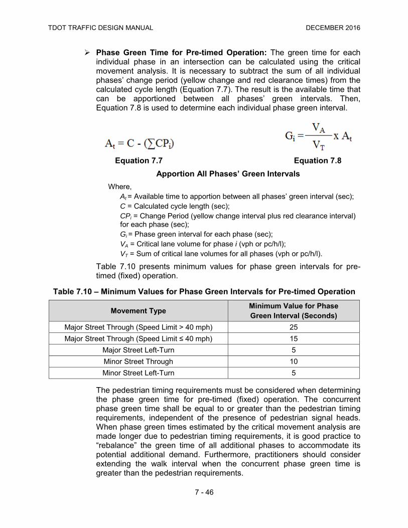
Phase Green Time for Pre-timed Operation: The green time for each individual phase in an intersection can be calculated using the critical movement analysis. It is necessary to subtract the sum of all individual phases’ change period (yellow change and red clearance times) from the calculated cycle length (Equation 7.7). The result is the available time that can be apportioned between all phases’ green intervals. Then, Equation 7.8 is used to determine each individual phase green interval.
Equation 7.7 Equation 7.8 Apportion All Phases’ Green Intervals
Where, At = Available time to apportion between all phases’ green interval (sec); C = Calculated cycle length (sec); CPi = Change Period (yellow change interval plus red clearance interval) for each phase (sec); Gi = Phase green interval for each phase (sec); VA = Critical lane volume for phase i (vph or pc/h/l); VT = Sum of critical lane volumes for all phases (vph or pc/h/l).
Table 7.10 presents minimum values for phase green intervals for pre-timed (fixed) operation.
Table 7.10 – Minimum Values for Phase Green Intervals for Pre-timed Operation
Movement Type Minimum Value for Phase Green Interval (Seconds)
Major Street Through (Speed Limit > 40 mph) 25 Major Street Through (Speed Limit ≤ 40 mph) 15
Major Street Left-Turn 5 Minor Street Through 10 Minor Street Left-Turn 5
The pedestrian timing requirements must be considered when determining the phase green time for pre-timed (fixed) operation. The concurrent phase green time shall be equal to or greater than the pedestrian timing requirements, independent of the presence of pedestrian signal heads. When phase green times estimated by the critical movement analysis are made longer due to pedestrian timing requirements, it is good practice to “rebalance” the green time of all additional phases to accommodate its potential additional demand. Furthermore, practitioners should consider extending the walk interval when the concurrent phase green time is greater than the pedestrian requirements.

TDOT TRAFFIC DESIGN MANUAL DECEMBER 2016
7 - 47
7.5.8 Actuated Phase Operation Signal Timing Parameters Actuated operation requires the calculation of the yellow change and red clearance intervals (See Section 7.5.5), walk and pedestrian clearance intervals (See Section 7.5.6) plus a minimum green, a maximum green, and a passage time for each timing plan to be used throughout the day. Figure 7.20 illustrates the relationship between actuated operation parameters. Minimum Green Guidelines: The minimum green parameter represents
the least amount of time that a green signal indication will be displayed when a phase is called. The minimum green should be set to meet driver expectancy, but its duration may also be based on considerations of detection design or pedestrian timing requirements.
• Driver Expectancy: The minimum green setting is intended to ensure that the green interval that is displayed is sufficiently long to allow the waiting queue enough time to perceive and react to the green indication. A minimum green that is too short may violate driver expectations, increasing the potential for rear-end crashes. Table 7.11 lists typical values for different facility types.
Table 7.11 – Typical Minimum Green Values Needed to Satisfy Driver Expectancy
Phase Type Facility Type Minimum Green Values Needed to Satisfy Driver Expectancy (Seconds)
Through Major Arterial (Speed Limit > 40 mph) 10 to 15 Major Arterial (Speed Limit ≤ 40 mph) 7 to 15
Minor Arterial, Collector, Local, Driveway 5 to 10 Left-Turn Any 5

TDOT TRAFFIC DESIGN MANUAL DECEMBER 2016
7 - 48
Figure 7.20 – Actuated Phase Operation Parameters
TDOT TRAFFIC DESIGN MANUAL DECEMBER 2016
7 - 49
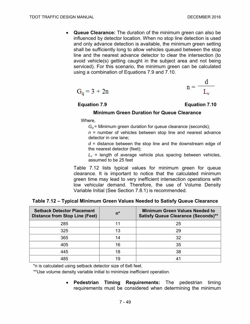
• Queue Clearance: The duration of the minimum green can also be influenced by detector location. When no stop line detection is used and only advance detection is available, the minimum green setting shall be sufficiently long to allow vehicles queued between the stop line and the nearest advance detector to clear the intersection (to avoid vehicle(s) getting caught in the subject area and not being serviced). For this scenario, the minimum green can be calculated using a combination of Equations 7.9 and 7.10.
Equation 7.9 Equation 7.10 Minimum Green Duration for Queue Clearance
Where, Gq = Minimum green duration for queue clearance (seconds); n = number of vehicles between stop line and nearest advance detector in one lane; d = distance between the stop line and the downstream edge of the nearest detector (feet); Lv = length of average vehicle plus spacing between vehicles, assumed to be 25 feet
Table 7.12 lists typical values for minimum green for queue clearance. It is important to notice that the calculated minimum green time may lead to very inefficient intersection operations with low vehicular demand. Therefore, the use of Volume Density Variable Initial (See Section 7.8.1) is recommended.
Table 7.12 – Typical Minimum Green Values Needed to Satisfy Queue Clearance
Setback Detector Placement Distance from Stop Line (Feet) n* Minimum Green Values Needed to
Satisfy Queue Clearance (Seconds)** 285 11 25 325 13 29 365 14 32 405 16 35 445 18 38 485 19 41
*n is calculated using setback detector size of 6x6 feet. **Use volume density variable initial to minimize inefficient operation.
• Pedestrian Timing Requirements: The pedestrian timing requirements must be considered when determining the minimum

TDOT TRAFFIC DESIGN MANUAL DECEMBER 2016
7 - 50
green time for actuated operation. First, if no pedestrian signal heads are present, the minimum green time shall be equal to or greater than the pedestrian timing requirements. Where pedestrian signal heads are present, practitioners should explore controller capabilities when deciding on the minimum green parameter. Older technology requires the minimum green time to be equal to or greater than the pedestrian timing requirements. Newer technology allows the minimum green time to be calculated for vehicular needs and the controller logic will automatically extend the minimum green time (to meet pedestrian requirements) upon activation of the pushbutton, providing more efficient operation.
Maximum Green Guidelines: The maximum green parameter represents the maximum amount of time that a green signal indication can be displayed in the presence of a serviceable conflicting call or another phase on recall. One common practice to estimate values for each phase maximum green parameter is to multiply the results for phase green time calculated using the critical movement analysis (See Section 7.5.7) by a factor of 1.25 to 1.50. With that, the maximum green has the potential to exceed the green duration to serve the typical maximum queue and thereby allow the phase to accommodate peaks in demand. Table 7.13 lists typical ranges for maximum green duration for different facility types. These values should be used as a starting point and adjusted based on field conditions.
Table 7.13 – Typical Values for Maximum Green
Phase Type Facility Type Maximum Green (Seconds)
Through
Major Arterial (Speed Limit > 40 mph) 50 to 70 Major Arterial (Speed Limit ≤ 40 mph) 40 to 60
Minor Arterial, Collector 30 to 50 Local, Driveway 20 to 40
Left-Turn Any 15 to 30
Passage Time Guidelines: The passage time parameter represents a controller function that extends the green signal indication beyond the minimum green time up to the maximum green time. It operates through a timer that starts to count down (from a user defined value) from the instant a detector is not occupied and is reset to its initial value with each subsequent actuation if it has not yet expired. If a conflicting call exists on another phase, the phase will gap out when the passage timer expires before the maximum green time is reached. The phase will max out when there is enough demand to continue to extend the phase up to the maximum green time. If a conflicting call does not exist on another phase, the current phase rests in green. Passage time is also known as vehicle

TDOT TRAFFIC DESIGN MANUAL DECEMBER 2016
7 - 51
extension time or gap time. Practitioners should refer to traffic signal controller manuals to determine the appropriate parameter to be programmed. It is critical to understand that passage time is directly related to efficiency at a signalized intersection. A passage time of two seconds would theoretically maintain a flow rate of 1,800 vehicles per hour. A passage time of three seconds would theoretically maintain a flow rate of 1,200 vehicles per hour. Therefore, as the passage time increases, the amount of inefficient flow increases because of acceptable larger headways and because of lost time generated when the traffic signal remains green for the length of the selected passage time after the last vehicle is detected (stop line scenario). The objective when determining the passage time value is to make it large enough to ensure that all vehicles in a moving queue are served but to not make it so large that it extends the green for randomly arriving traffic. The appropriate passage time used for a particular signal phase is dependent on many considerations, including: number of detection zones per lane, location of each detection zone, detection zone length, detection operating mode, and approach speed (See Chapter 8). Ideally, the detection design is established and the passage time is determined so that the “detection system” provides efficient queue service and, for high-speed approaches, safe phase termination.
• Passage time for stop line detection: Equation 7.11 can be used to calculate the passage time for stop line detection (presence mode).
Equation 7.11 – Passage Time
Where, PT = Passage Time (sec); MAH = Maximum Allowable Headway (sec), use 3 seconds; Lv = Length of Vehicle (use 20 feet); Ld = Length of Detection Zone (feet); v = Approach Speed (mph) (the Posted Speed Limit is Recommended).

TDOT TRAFFIC DESIGN MANUAL DECEMBER 2016
7 - 52
For stop line detection, the longer the detection zone length, the shorter the passage time, thus providing snappier operation. Table 7.14 lists typical passage time values for stop line detection based on Equation 7.11. These values should be used as a starting point and adjusted based on field conditions.
Table 7.14 – Typical Values for Passage Time for Stop Line Detection
Detection Zone Length (Feet)
Passage Time (Seconds) for Approach Speed (mph)* 25** 30 35 40 45
20 1.9 2.1 2.2 2.3 2.4 25 1.8 2.0 2.1 2.2 2.3 30 1.6 1.9 2.0 2.1 2.2 35 1.5 1.8 1.9 2.1 2.2 40 1.4 1.6 1.8 2.0 2.1 45 1.2 1.5 1.7 1.9 2.0 50 1.1 1.4 1.6 1.8 1.9 55 1.0 1.3 1.5 1.7 1.9 60 0.8 1.2 1.4 1.6 1.8 65 0.7 1.1 1.3 1.6 1.7 70 0.5 1.0 1.2 1.5 1.6 75 0.4 0.8 1.1 1.4 1.6 80 0.3 0.7 1.1 1.3 1.5
*The passage time may be increased by up to 1.0 second if the approach is on a steep upgrade and/or there is a large percentage of heavy vehicles. **For left-turn movements, use an approach speed of 25 mph.
• Passage Time for Advance Detection: Advance detection is typically used for indecision zone protection (See Section 8.5.2). Here, the passage time parameter should extend the green interval long enough for a vehicle to clear the indecision zone. A passage time of 3.5 seconds is typically sufficient to clear a vehicle for the indecision zones presented in Table 8.3, independent of approach speed. It is necessary to note that no extend parameter or volume density gap reduction (See Section 7.8.1) is used in combination with the recommended passage time. When a combination of stop line detection and advance detection is available at an intersection, typically the queue detector parameter is used and the passage time of 3.5 seconds is set for the advance detection.

TDOT TRAFFIC DESIGN MANUAL DECEMBER 2016
7 - 53
7.6 Traffic Signal Coordination Coordination can be defined as the ability to synchronize multiple intersections to enhance the operation of one or more directional movements in a system. The following sections explore coordination objectives and fundamentals, introduce coordination parameter guidelines, and discuss coordination complexities.
7.6.1 Traffic Signal Coordination Objectives The latest National Traffic Signal Report Card states a common objective for the coordination of traffic signals:
“The intent of coordinating traffic signals is to provide smooth flow of traffic along streets and highways in order to reduce travel times, stops and delay.”
In addition, coordination may be used to maximize throughput on a corridor during specific times of the day. Practitioners should be aware that typical software programs have a focus on system vehicle delay, which may not be the selected operational objective for coordination. Well-timed coordination systems may also be beneficial to reduce driver frustration, improve safety (less stops resulting in less rear-end crashes), and to reduce fuel consumption and emissions.
7.6.2 Fundamentals of Traffic Signal Coordination The understanding of the following concepts and tools are fundamental for traffic signal coordination design. Determining Intersections to be Included in the System: Determining
which intersections should be included in a coordinated system is important. Typically, intersections spaced within ½ mile of each other will benefit from coordination, especially during periods of large traffic demand when platoons of vehicles may form. Intersections spaced one mile or more apart may benefit from coordination if there is minimal access turbulence on segments. Otherwise, Equation 7.12 can be used to calculate the coupling index to assist in the decision process.
Equation 7.12 – Coupling Index
Where, CI = coupling index; V = two-way traffic volume on the street to be coordinated (vehicles/hour); L = segment length (feet), measured between the center of the subject intersection and the center of the adjacent signalized intersection.

TDOT TRAFFIC DESIGN MANUAL DECEMBER 2016
7 - 54
The coupling index should be analyzed for specific traffic conditions during different times of the day based on the scale below. Adjacent segments that have an index of 0.5 or more are considered for grouping in the signal system.
• 0.3 or less: unlikely to benefit from coordination;
• 0.3 to 0.5: segment likely to benefit if mid-segment access point activity is low and turn-bays are provided on the major street at each signalized intersection;
• 0.5 or more: likely to benefit from coordination. It is important to notice that the system cycle length (See Section 7.6.3) may also end up influencing which signalized intersections should be included in the system. As additional intersections are added to a system, it becomes increasingly difficult to provide progression. Sometimes it is better to break a long corridor into smaller segments. Typically, the “stop” location should be where there is adequate distance between intersections to provide storage for vehicles without impacting the upstream intersection.
Coordinated Phases: Coordination requires the designation of a phase or multiple phases as the coordinated phase(s). They are selected (toggled) at a specific traffic signal controller menu and all other phases being used at the intersection are automatically set as non-coordinated phases. Coordinated phases are distinguished from non-coordinated phases because they are guaranteed a minimum amount of green time every cycle. The guaranteed green interval can be used to maintain the coordinated relationship between intersections.
Time-Space Diagrams: Time-space diagrams are a visual tool that practitioners use to analyze coordination strategies and modify traffic signal timing plans. A time-space diagram focuses on coordinated phases and illustrates the relationship between intersection spacing, signal timing, and vehicle movement. Figure 7.21 illustrates a typical time-space diagram. Basically, time-space diagrams have a graphical representation of distance on the y-axis and time on the x-axis, overlaid by the ring-and-barrier diagram for each intersection. Protected left-turn movements may be represented on each ring-and-barrier by directional hatching. This helps practitioners identify what point in the cycle a vehicle can progress. A very important component of time-space diagrams is to depict vehicle trajectory lines representing movement either north/south or east/west. Flat lines represent stopped vehicles and possible queuing while a diagonal line represents vehicles’ movement at design speed. Furthermore, the master clock and the local clock can also be represented in a time-space diagram. The master clock is the background timing mechanism within the controller logic that starts daily at a pre-defined time, usually midnight (lower traffic volumes). Each local controller clock is referenced to the master clock for coordination to occur.
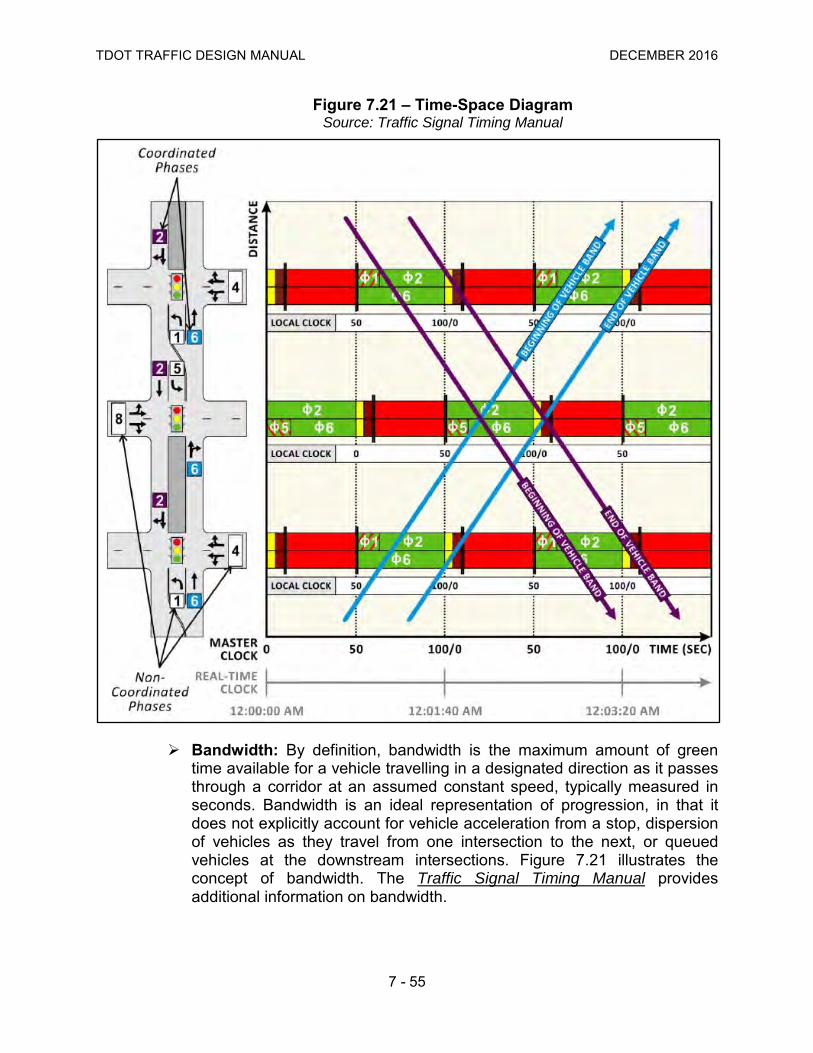
TDOT TRAFFIC DESIGN MANUAL DECEMBER 2016
7 - 55
Figure 7.21 – Time-Space Diagram Source: Traffic Signal Timing Manual
Bandwidth: By definition, bandwidth is the maximum amount of green time available for a vehicle travelling in a designated direction as it passes through a corridor at an assumed constant speed, typically measured in seconds. Bandwidth is an ideal representation of progression, in that it does not explicitly account for vehicle acceleration from a stop, dispersion of vehicles as they travel from one intersection to the next, or queued vehicles at the downstream intersections. Figure 7.21 illustrates the concept of bandwidth. The Traffic Signal Timing Manual provides additional information on bandwidth.

TDOT TRAFFIC DESIGN MANUAL DECEMBER 2016
7 - 56
System Configurations: The way that the coordinated system is configured depends on availability of communication at individual intersections. Under time base control, each intersection traffic signal controller works by itself and will be related to each other by the synchronized internal clocks (or external GPS clocks). No physical interconnect exists. Timing plans are developed and entered individually into each controller. Additional maintenance may be required due to drifting of individual controller clocks. Under a closed loop system, each intersection traffic signal controller is interconnected and communicates to an on-street master signal controller (which can be configured to communicate to a central system). Timing plans can be downloaded to individual intersections via the master signal controller. Lastly, a coordinated system may be configured to have all individual intersections communicating directly to a central system. The typical types of interconnection used in coordinated systems are twisted-pair, fiber optic, telephone lines, wireless radio, Ethernet, etc. Current technology enables the ability of interconnected systems to provide extensive system monitoring with data collection, analysis functions, reporting, and status information beyond the usual uploading and downloading of timing settings. It is recommended that signal timing plans reside in the local controllers in the field to avoid potential problems with communication failures.
7.6.3 Traffic Signal Coordination Parameters Guidelines Several traffic signal parameters must be programmed in the traffic signal controller for coordination to work. The following sections provide guidelines regarding system cycle length, splits, offsets, force-offs, and pedestrian parameters. System Cycle Length: In coordination, all intersections included in a
system must have a common cycle length in order to maintain a consistent time-based relationship between intersections. It is known as system cycle. For coordination, traffic signal timing software is typically used to determine appropriate system cycle lengths with data collected at representative periods of the day. Optimization models generally use a given set of inputs (including the range of preferred cycle lengths) and estimated performance measures to determine an optimal solution. Practitioners should have an understanding of desired objectives (See Section 7.6.1) and software limitations. Manual methods for determining system cycle length can also be used in simple networks, like downtown areas, based on constant block spacing. Nevertheless, system cycle lengths are frequently selected to address operations at a critical (or highest volume) intersection in a group of coordinated signalized intersections. It is good practice to perform an analysis on intersections requiring longer cycle lengths to determine if operation would benefit from having the particular intersection operating independently, in full actuated

TDOT TRAFFIC DESIGN MANUAL DECEMBER 2016
7 - 57
mode. Imposing a long system cycle length may increase overall congestion and delay in the system. A scenario with a smaller intersection requiring a shorter cycle length may benefit by running “double cycles” (half the system cycle length), where phases are serviced twice as often as other intersections in the system.
Splits: Splits are the portion of the system cycle allocated to each phase, including the green interval, yellow change, and red clearance intervals. Splits are selected based on individual intersection phasing and expected demand. Therefore, splits may vary from intersection to intersection. Similarly to system cycle length determination, splits are determined using traffic signal timing software. When implementing splits on a traffic signal controller, the sum of the phase splits must be equal to or less than the programmed cycle length. Some traffic signal controllers will allow splits to be less than pedestrian requirements. This is intended for situations in which there are few pedestrian calls. The traffic signal controller may need to transition (See Section 7.6.4) after servicing a pedestrian call under this scenario.
Offsets: Offset is the time that elapses between the master clock and the offset reference point at each local intersection included in the system. Therefore, each signalized intersection will also have a relative offset to each other. It is through this association that the coordinated phase is aligned between intersections to create the relationship for synchronized movements. The offset reference point is a user defined traffic signal controller parameter that helps structure the relationship between coordinated intersections by defining the point in time when the cycle begins timing. Offsets should be chosen based on the actual or desired travel speed between intersections, distance between signalized intersections, and traffic volumes. In an ideal coordinated system, offsets would allow platoons (leaving an upstream intersection at the start of green) to arrive at a downstream intersection near the start of green, or after the queue from minor streets or driveways discharged (green starts early enough to clear queued vehicles before the platoon arrives). Field observations and software outputs (time-space diagrams) should be used in combination to optimize the system. Figure 7.22 illustrates the relationship between cycle, split, and offset.
Force-offs: Force-offs are used to enforce phase splits, making sure the traffic signal controller logic returns to serve the coordinated phases no later than the programmed time. There are two types of force-offs, fixed and floating, that determine how unused actuated green time on the non-coordinated phases is shared with subsequent phases. Under fixed force-off, when any non-coordinated phase gaps out, its remaining green time will be made available to the following phase in sequence to use. Under floating force-off, when any non-coordinated phase gaps out, its remaining green time will be transferred to the coordinated phase. The selection of force-off mode is related to operational objectives. Floating force-offs favor

TDOT TRAFFIC DESIGN MANUAL DECEMBER 2016
7 - 58
the coordinated phases, as they do not allow non-coordinated phases to inherit time. Therefore, any unused time will always be transferred to the coordinated phase. Floating force-off is recommended if large queues remain at the start of green on coordinated phases or if minor movements have low traffic demand. Fixed force-offs can be beneficial when fluctuations in traffic demand exist and a non-coordinated phase needs more green time during a cycle to serve a surge in traffic. In this scenario, unused green time may be available to a subsequent phase, that in turn may not need all of the available time and “passes” it along to the next phase in sequence until any remaining green time is finally transferred to the coordinated phase. Fixed force-offs can also help to prevent the early return to green on the coordinated phases, reducing perceived delay along the corridor. Early return to green is a term used to describe the servicing of a coordinated phase in advance of its programmed begin time as a result of unused time from non-coordinated phases.

TDOT TRAFFIC DESIGN MANUAL DECEMBER 2016
7 - 59
Figure 7.22 – Cycle, Split and Offset Relationships

TDOT TRAFFIC DESIGN MANUAL DECEMBER 2016
7 - 60
Pedestrian Timing and Walk Modes: Pedestrians can have a direct impact on coordination along a corridor when the time required to serve them is larger than the green time needed for servicing vehicles. When pedestrian service is actuated and demand is relatively low, it may be desirable to allocate a split time that is less than the time required to serve a pedestrian. This scenario would require the traffic signal controller logic to be shifted out of coordination, but nevertheless, it may be more effective to transition (See Section 7.6.4) back for the occasional pedestrian, than to serve pedestrian timing every cycle. As a general rule, pedestrian crossing time should be provided within the split time for the phase whenever pedestrian volume is enough that it can repeatedly cause disruption to coordination (goes into transition). It can vary on different timing plans. This strategy is typically used when a pedestrian call occurs more than 20 percent of the cycles. Practitioners can select pedestrian parameters to accommodate different operational objectives. The rest in walk parameter makes the traffic signal controller logic dwell in the pedestrian walk interval while the coordinated phase is green. This mode is often used when there are high pedestrian volumes (downtown areas, schools, etc), during appropriate times of the day (when pedestrians are present) providing better service to pedestrians. However, this walk mode may delay the minor street movement’s vehicular service because the traffic signal controller still has to time the flashing don’t walk interval when a conflicting call comes in. Figure 7.23 illustrates the rest in walk parameter.
7.6.4 Traffic Signal Coordination Complexities The spacing between signalized intersections is critical for achieving appropriate coordination. Evenly spaced intersections provide a better environment for two-way coordination than intersections that don’t present consistent spacing. Furthermore, access management takes an important role in coordination as a designed bandwidth may be seriously compromised with the addition of a signalized intersection in an existing system. Also, corridor operations are improved when driveway connections (from parking lots, etc.) are managed and kept to a minimum, providing less platoon disruption. Turn-bay interactions can impact the effective capacity of an intersection. Turn-bay overflows can adversely impact progression by disrupting through traffic from proceeding to downstream intersections. Conversely, queued vehicles on the through movement may block access to the turn-bay causing operational issues as well. See Table 7.3 for left-turn phase sequence strategies to minimize turn-bay challenges. Heavy volumes from minor streets, interchanges, or driveways can affect the ability to progress through movements along a corridor. These surplus demands often enter the system outside the band established for through movements and disrupt operations. Downstream intersection timing may need to be adjusted for this scenario.
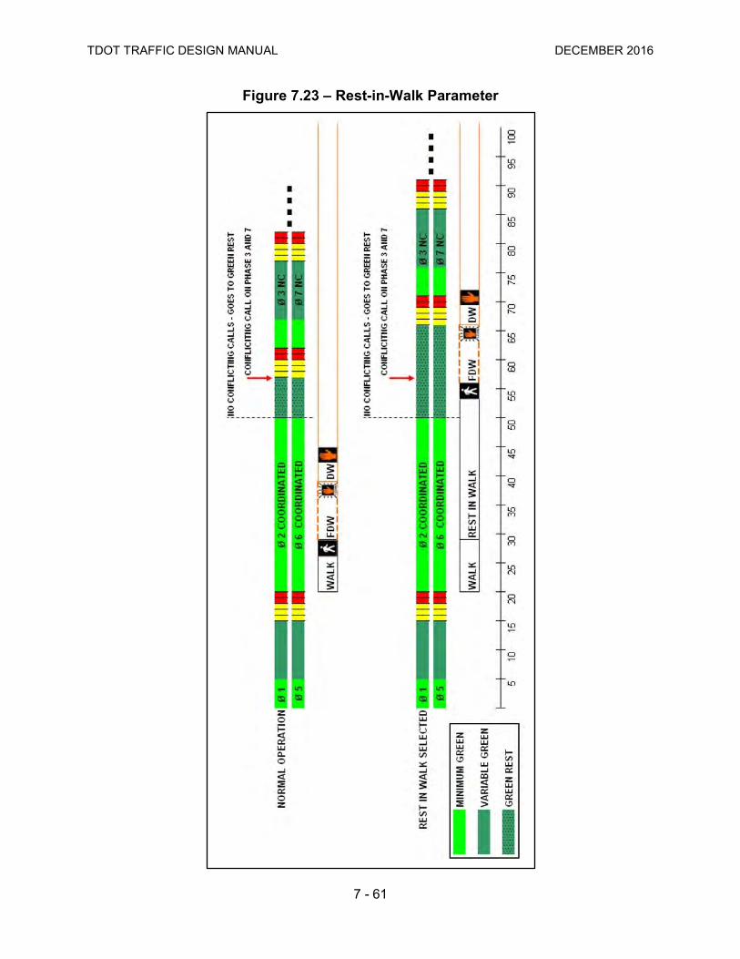
TDOT TRAFFIC DESIGN MANUAL DECEMBER 2016
7 - 61
Figure 7.23 – Rest-in-Walk Parameter
TDOT TRAFFIC DESIGN MANUAL DECEMBER 2016
7 - 62
Another coordination issue is the early return to green (See Section 7.6.3) and selection of force-off modes is crucial for reducing perceived delay. Lastly, but potentially very disruptive to coordination, is when the traffic signal controller undergoes transition logic. Transition is the process of either entering into a coordinated timing plan from free operation or changing between two plans (potentially different cycle lengths, splits and offsets). Transition may also occur after preemption or due to a pedestrian actuation, where pedestrian timing requirements exceed the allocated split time for the concurrent phase. Technically, under any of these scenarios, the local offset reference point may be shifted, requiring an algorithm to adjust the cycle to synchronize the local clock with the master (system) clock. The process may take from one to five cycle lengths, a period of time where the system is not responding to coordination as designed. Practitioners should explore appropriate transition modes for the traffic signal controller in use at the intersection according to system objectives. It is best practice to avoid frequent changes to timing plans, minimizing the chance for transition to happen and allowing a coordinated pattern to be running in a specific timing plan for at least 30 minutes. Similarly, a timing plan should be implemented before the start (5-10 minutes earlier) of the traffic demand period for which it was developed, especially if it is a peak period, to minimize the disruption that transition can cause at such critical time.
7.7 Traffic Signal Timing Plans A traffic signal timing plan is a unique set of signal timing parameters (See Section 7.5) that can be scheduled to run at specific periods of the day, week, month, or year. In addition, signal timing plans can be customized to weekdays, weekends, or specific days (i.e. holidays, special events, etc.). Typically, signalized intersections experience a peak period during the morning, mid-day, and evening, warranting different signal timing plans. Practitioners should develop signal timing plans based on specific outcomes to help agencies meet operational objectives during different time periods (e.g. minimize delay vs. control queue spillbacks vs. maximize throughput, etc). For coordination (See Section 7.6), specific patterns should be developed, including cycle length, split, offset, etc., that will integrate with signal timing plans. Signal timing plans should always be monitored after installation and field adjustments performed (fine-tuned) to ensure safe and efficient operations.
7.7.1 Timing Software Computer-based tools are available to calculate and evaluate traffic signal timing, but software capabilities and limitations need to be recognized. A good rule of thumb is for practitioners to have a sense for the expected answer (based on field knowledge or a quick critical movement analysis) to check if the software results are reasonable. Typical traffic signal timing software includes: Synchro, PASSER, Transit 7F, TEAPAC, Tru-Traffic, etc. Simulation models may be of great benefit for practitioners to evaluate signal timing alternatives, explore

TDOT TRAFFIC DESIGN MANUAL DECEMBER 2016
7 - 63
features, and demonstrate potential operational improvements to public officials. Similar to traffic signal timing software, simulation capabilities and limitations need to be recognized.
7.8 Advanced Traffic Signal Operations Advanced traffic signal systems rely on dynamic signal timing adjustments to enhance traffic operations. Most advanced systems require considerable investment from local agencies for equipment and maintenance. Therefore, a SEA report is recommended to determine if a system is appropriate for a given location based on local needs and requirements. For additional information on SEA requirements, see TDOT’s ITS Project Development Guidelines. The following information explores volume density, traffic responsive, and adaptive signal control technology systems.
7.8.1 Volume Density Volume density (also known as density timing) is an enhanced actuated operation where actuated controller parameters (minimum green and passage time) are automatically adjusted to improve intersection efficiency according to varying traffic demand. Variable initial modifies the minimum green parameter while gap reduction modifies the passage time parameter functionality. Variable Initial: Section 7.5.8 provided guidelines for setting the minimum
green parameter for actuated operation. It mentioned that when detection design consists of no stop line detection and only advance detectors are present, the minimum green needs to be long enough to allow all vehicles queued between the stop line and the nearest advance detector to clear the intersection. This scenario may lead to a very long minimum green (inefficient operation with low traffic volumes) due to long detector advance distances (typically beyond 140 feet). Here is where the use of variable initial becomes beneficial. The variable initial allows the minimum green to be automatically calculated by the traffic signal controller based on the number of detection actuations placed during the yellow change and the red intervals. Therefore, the amount of minimum green is tailored to existing traffic demand, providing more efficient operations. This operation requires the programming of three traffic signal controller parameters (minimum initial, added initial, and maximum initial) and appropriate detection settings. Due to non-standard traffic signal terminology, practitioners should refer to traffic signal controller manuals to determine the appropriate parameters to be programmed. Figure 7.24 illustrates variable initial operation.

TDOT TRAFFIC DESIGN MANUAL DECEMBER 2016
7 - 64
Figure 7.24 – Volume Density (Variable Initial) Source: Traffic Signal Timing Manual
• Minimum Initial: The minimum initial is the shortest amount of time that the green interval will be active during volume density operation. Its setting is based on the lower range value for minimum green time to satisfy driver expectancy. The minimum initial is intended to allow time for motorists to respond to the onset of the green indication. If pedestrian timing requirements are a concern, the minimum initial timing should follow the guidelines presented for minimum green timing in Section 7.5.8. Table 7.16 provides typical values for minimum initial settings under volume density operations.
Table 7.15 – Volume Density Typical Values for Minimum Initial Settings
Facility Type Time (Seconds) Major Arterial (Speed Limit > 40 mph) 10 Major Arterial (Speed Limit > 40 mph) 7
Minor Arterial, Collector 5
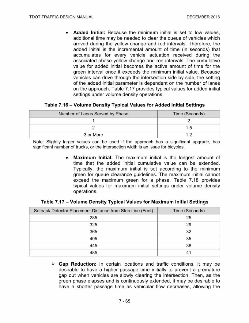
TDOT TRAFFIC DESIGN MANUAL DECEMBER 2016
7 - 65
• Added Initial: Because the minimum initial is set to low values, additional time may be needed to clear the queue of vehicles which arrived during the yellow change and red intervals. Therefore, the added initial is the incremental amount of time (in seconds) that accumulates for every vehicle actuation received during the associated phase yellow change and red intervals. The cumulative value for added initial becomes the active amount of time for the green interval once it exceeds the minimum initial value. Because vehicles can drive through the intersection side by side, the setting of the added initial parameter is dependent on the number of lanes on the approach. Table 7.17 provides typical values for added initial settings under volume density operations.
Table 7.16 – Volume Density Typical Values for Added Initial Settings
Number of Lanes Served by Phase Time (Seconds) 1 2 2 1.5
3 or More 1.2 Note: Slightly larger values can be used if the approach has a significant upgrade, has significant number of trucks, or the intersection width is an issue for bicycles.
• Maximum Initial: The maximum initial is the longest amount of time that the added initial cumulative value can be extended. Typically, the maximum initial is set according to the minimum green for queue clearance guidelines. The maximum initial cannot exceed the maximum green for a phase. Table 7.18 provides typical values for maximum initial settings under volume density operations.
Table 7.17 – Volume Density Typical Values for Maximum Initial Settings
Setback Detector Placement Distance from Stop Line (Feet) Time (Seconds) 285 25 325 29 365 32 405 35 445 38 485 41
Gap Reduction: In certain locations and traffic conditions, it may be desirable to have a higher passage time initially to prevent a premature gap out when vehicles are slowly clearing the intersection. Then, as the green phase elapses and is continuously extended, it may be desirable to have a shorter passage time as vehicular flow decreases, allowing the

TDOT TRAFFIC DESIGN MANUAL DECEMBER 2016
7 - 66
phase to gap out more efficiently, potentially minimizing the delay for conflicting movements. This can be accomplished by the gap reduction feature of volume density operation. Signalized intersections with upgrade approaches, high traffic volumes, or considerable heavy vehicle volume may benefit from gap reduction. This operation requires the programming of four traffic signal controller parameters (passage time, time before reduction, time to reduce, and minimum gap). Gap reduction can be used with stop line detection and advance detection. Due to non-standard traffic signal terminology, practitioners should refer to traffic signal controller manuals to determine the appropriate parameters to be programmed. Figure 7.25 illustrates gap reduction operation.
Figure 7.25 – Volume Density (Gap Reduction) Source: Traffic Signal Timing Manual
• Passage Time: For stop line detection, the passage time should be set using Equation 7.11 (See Section 7.5.8), but a maximum allowable headway of four seconds should be used. Table 7.19 provides typical passage time values for stop line detection. For advance detection, the passage time should be calculated as the time it takes a vehicle to travel from the nearest advance detector to the stop line (distance from the detector/approach speed). When indecision zone protection is provided (See Section 8.5.2), the use of gap reduction is not recommended.

TDOT TRAFFIC DESIGN MANUAL DECEMBER 2016
7 - 67
Table 7.18 – Volume Density Gap Reduction Settings for Passage Time (Stop Line Detection)
Detection Zone
Length (Feet)
Passage Time (Seconds) for Approach Speed (mph)
25 30 35 40 45 50 55 60 65
20 2.9 3.1 3.2 3.3 3.4 3.5 3.5 3.5 3.6 25 2.8 3.0 3.1 3.2 3.3 3.4 3.4 3.5 3.5 30 2.6 2.9 3.0 3.1 3.2 3.3 3.4 3.4 3.5 35 2.5 2.8 2.9 3.1 3.2 3.3 3.3 3.4 3.4 40 2.4 2.6 2.8 3.0 3.1 3.2 3.3 3.3 3.4 45 2.2 2.5 2.7 2.9 3.0 3.1 3.2 3.3 3.3 50 2.1 2.4 2.6 2.8 2.9 3.0 3.1 3.2 3.3 55 2.0 2.3 2.5 2.7 2.9 3.0 3.1 3.1 3.2 60 1.8 2.2 2.4 2.6 2.8 2.9 3.0 3.1 3.2 65 1.7 2.1 2.3 2.6 2.7 2.8 2.9 3.0 3.1 70 1.5 2.0 2.2 2.5 2.6 2.8 2.9 3.0 3.1 75 1.4 1.8 2.1 2.4 2.6 2.7 2.8 2.9 3.0 80 1.3 1.7 2.1 2.3 2.5 2.6 2.8 2.9 3.0
*The passage time may be increased by up to 1.0 second if the approach is on a steep upgrade and/or there is a large percentage of heavy vehicles.
• Time Before Reduction: The time before reduction determines the amount of time to be elapsed after a conflicting call is received and before the passage time is allowed to be reduced. In most cases, it should equal the minimum green setting (See Section 7.5.8). Table 7.20 provides typical time before reduction values.
Table 7.19 – Volume Density Gap Reduction Settings for Time Before Reduction
Minimum Green (Seconds) Time (Seconds) 5 10
10 10 15 15 20 20
• Time to Reduce: The time to reduce determines the amount of time to be elapsed during the linear reduction of the passage time to the minimum gap value. It should equal one-half of the difference between the maximum green and the minimum green setting. Table 7.21 lists typical values for the time to reduce parameter.
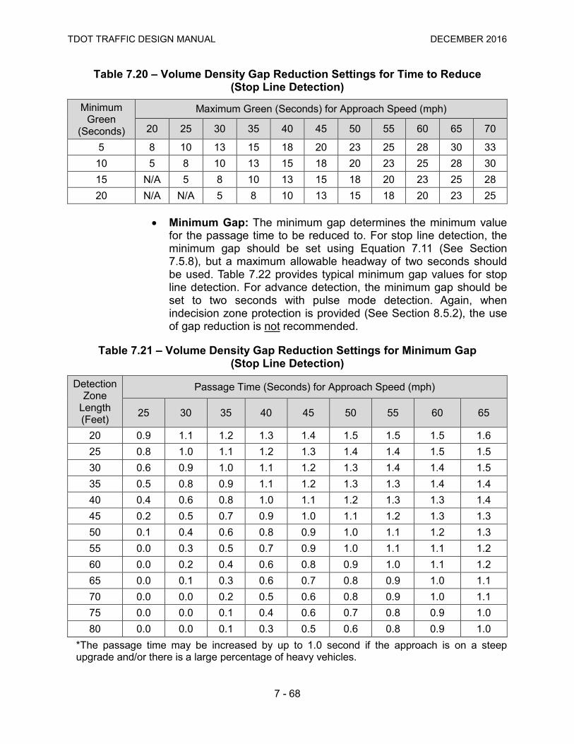
TDOT TRAFFIC DESIGN MANUAL DECEMBER 2016
7 - 68
Table 7.20 – Volume Density Gap Reduction Settings for Time to Reduce (Stop Line Detection)
Minimum Green
(Seconds)
Maximum Green (Seconds) for Approach Speed (mph)
20 25 30 35 40 45 50 55 60 65 70
5 8 10 13 15 18 20 23 25 28 30 33 10 5 8 10 13 15 18 20 23 25 28 30 15 N/A 5 8 10 13 15 18 20 23 25 28 20 N/A N/A 5 8 10 13 15 18 20 23 25
• Minimum Gap: The minimum gap determines the minimum value for the passage time to be reduced to. For stop line detection, the minimum gap should be set using Equation 7.11 (See Section 7.5.8), but a maximum allowable headway of two seconds should be used. Table 7.22 provides typical minimum gap values for stop line detection. For advance detection, the minimum gap should be set to two seconds with pulse mode detection. Again, when indecision zone protection is provided (See Section 8.5.2), the use of gap reduction is not recommended.
Table 7.21 – Volume Density Gap Reduction Settings for Minimum Gap (Stop Line Detection)
Detection Zone
Length (Feet)
Passage Time (Seconds) for Approach Speed (mph)
25 30 35 40 45 50 55 60 65
20 0.9 1.1 1.2 1.3 1.4 1.5 1.5 1.5 1.6 25 0.8 1.0 1.1 1.2 1.3 1.4 1.4 1.5 1.5 30 0.6 0.9 1.0 1.1 1.2 1.3 1.4 1.4 1.5 35 0.5 0.8 0.9 1.1 1.2 1.3 1.3 1.4 1.4 40 0.4 0.6 0.8 1.0 1.1 1.2 1.3 1.3 1.4 45 0.2 0.5 0.7 0.9 1.0 1.1 1.2 1.3 1.3 50 0.1 0.4 0.6 0.8 0.9 1.0 1.1 1.2 1.3 55 0.0 0.3 0.5 0.7 0.9 1.0 1.1 1.1 1.2 60 0.0 0.2 0.4 0.6 0.8 0.9 1.0 1.1 1.2 65 0.0 0.1 0.3 0.6 0.7 0.8 0.9 1.0 1.1 70 0.0 0.0 0.2 0.5 0.6 0.8 0.9 1.0 1.1 75 0.0 0.0 0.1 0.4 0.6 0.7 0.8 0.9 1.0 80 0.0 0.0 0.1 0.3 0.5 0.6 0.8 0.9 1.0
*The passage time may be increased by up to 1.0 second if the approach is on a steep upgrade and/or there is a large percentage of heavy vehicles.

TDOT TRAFFIC DESIGN MANUAL DECEMBER 2016
7 - 69
7.8.2 Traffic Responsive Plan Selection Systems A TOD plan selection works well when traffic conditions are consistent and predictable – that is, similar traffic patterns generally occur during the same times each day. When an incident, a planned event (e.g., construction, county fair, football game, etc.), extreme weather, or any other unusual occurrence causes a significant change in the normal traffic conditions, the timing plan selected by the TOD method may not be the plan best suited to current conditions. To address this situation, the TRPS uses data from traffic detectors, rather than TOD, to automatically select the coordinated timing plan best suited to current conditions. Plan selection for responsive operations may also be invoked manually. Agencies operating traffic signals from their traffic management centers have the ability to use predetermined plans for planned special events or recurring congestion on an as-needed basis. TRPS normally takes place on a field master or central system. Considerable effort may be needed to: Identify vehicle detectors that will provide adequate representation of
traffic conditions; Establish appropriate parameter values associated with detectors; Establish appropriate threshold values to trigger the implementation of
new timing plans; Fine-tune once TRPS is implemented.
Historical traffic count data is necessary before the detector selection and setup begins. Furthermore, transition (See Section 7.6.4) may become a problem due to frequent changes in the timing plan. Therefore, it is recommended that the current timing plan be running for a minimum amount of time before a new plan can be implemented, and the new timing plan must typically be a certain percentage improvement over the current running plan. Traffic responsive plan selection systems merely select a timing plan to operate, but do not make changes to the timings specified in the timing plan. That is the role of adaptive traffic signal control. For additional information regarding TRPS systems, refer to the Traffic Signal Timing Manual.
7.8.3 Adaptive Signal Control Technology Systems ASCT systems are a concept where vehicular traffic in a network is detected at an upstream and/or downstream point. A model is used to predict where the detected vehicular traffic will be and an algorithm makes signal adjustments at the downstream intersections based on those predictions. The signal controller utilizes these algorithms to compute optimal signal timings based on detected traffic volume and simultaneously implements the timings in real-time. This real-time optimization allows a signal system to react to traffic volume variations, resulting in potential reduced system user delay, shorter queues, and decreased travel times. Adaptive systems are critically linked to good, reliable detection systems. ASCT systems will provide the best operational improvements where: Traffic conditions fluctuate randomly on a day-to-day basis;

TDOT TRAFFIC DESIGN MANUAL DECEMBER 2016
7 - 70
Traffic conditions change rapidly due to new developments in land use; Incidents, crashes, or other events result in unexpected changes to traffic
demand; Other disruptive events, such as preemption, require a response; Under-saturated conditions exist.
It is important to understand that ASCT systems are not set-and-forget systems. They require ongoing fine-tuning and higher levels of maintenance than traditional systems, in order to keep the detection and communications infrastructure working at a high level of performance. For additional information regarding ASCT systems, refer to the Traffic Signal Timing Manual.
7.9 Traffic Signal Priority TSP is a type of preferential treatment based on an operational strategy communicated between vehicles and traffic signals (or through detection vehicle type classification) to alter the signal timing for the benefit or priority of those vehicles (mostly transit and heavy trucks). Coordination will not be affected by priority. Service is not guaranteed during a priority request. TSP may be accomplished through the following methods: Green/Phase Extension: Involves the extension of the preferred phase green
interval past its normal termination point to prevent long delays for preferred vehicles that are anticipated to arrive near the end of the green interval (transit and heavy trucks);
Red Truncation/Early Green: Involves shortening the duration of non-preferred phases in order to return earlier than normal to the green interval of the preferred phase, preventing additional delays to preferred vehicles (transit and heavy trucks);
Phase Insertion: Involves the activation of a special, dedicated phase that is not served during normal (non-preferred) operations, and is only displayed when a preferred vehicle has been detected at the intersection. It is typically used to provide service to lanes dedicated to preferred vehicles or to support queue jumps, allowing preferred vehicles to enter a downstream link ahead of the normal traffic stream;
Phase Sequence Change: Involves changing the sequence of phases to provide more immediate service to the preferred vehicle;
Phase Skipping: Involves skipping service for non-preferred phases that would normally be served, in order to expedite service to preferred phases.
The MUTCD Section 4D.27 requires that during priority control and during the transition into or out of priority control: The shortening or omission of any yellow change interval, and of any red
clearance interval that follows, shall not be permitted;

TDOT TRAFFIC DESIGN MANUAL DECEMBER 2016
7 - 71
The shortening of any pedestrian walk interval below that time described in Section 4E.06 shall not be permitted;
The omission of a pedestrian walk interval and its associated change interval shall not be permitted, unless the associated vehicular phase is also omitted or the pedestrian phase is exclusive;
The shortening or omission of any pedestrian change interval shall not be permitted;
A signal indication sequence from a steady yellow signal indication to a green signal indication shall not be permitted.
For additional information on traffic signal priority, refer to the Traffic Signal Timing Manual and to the Transit Signal Priority Handbook.
7.10 Traffic Signal Preemption Traffic signal preemption is a type of preferential treatment that involves the transfer of normal operation of a traffic control signal to a special control mode of operation, typically including trains and emergency vehicles. Coordination will be affected by preemption and a service is guaranteed during a preemption request. The MUTCD Section 4D.27 requires that during the transition into preemption control: The yellow change interval, and any red clearance interval that follows, shall not
be shortened or omitted; The shortening or omission of any pedestrian walk interval and/or pedestrian
change interval shall be permitted; The return to the previous green signal indication shall be permitted following a
steady yellow signal indication in the same signal face, omitting the red clearance interval, if any.
The MUTCD Section 4D.27 further requires that during preemption control and during the transition out of preemption control: The shortening or omission of any yellow change interval, and of any red
clearance interval that follows, shall not be permitted; A signal indication sequence from a steady yellow signal indication to a green
signal indication shall not be permitted. The following describes emergency vehicle preemption and railroad preemption.
7.10.1 Emergency Vehicle Preemption Various mechanisms can be used to preempt traffic signals so that emergency vehicles are provided with safe right-of-way as soon as practical. Emergency preemption systems allow emergency vehicles to interrupt the normal sequence of traffic signal phasing and provide preferential treatment to the approach with the emergency vehicle. To accomplish the operation, a flexible response system

TDOT TRAFFIC DESIGN MANUAL DECEMBER 2016
7 - 72
is deployed using either a light emitter or siren in the vehicle and a receiver connected to the traffic signal controller at various intersections. The receiver sends a message to the signal controller, which terminates the current phase and skips to the green interval on the required approach. Emergency vehicle preemption should be considered at signalized intersections along key roadways and routes to and from hospitals, fire stations, and police stations. Figure 7.26 shows an emergency vehicle preemption sequence. TDOT will normally install emergency vehicle preemption detection devices (optical or siren activated priority control systems) as a part of a traffic signal installation or upgrade project, upon request of the local governing agency. TDOT will normally not provide emitter/transponders unless the project’s purpose is to provide a city-wide or area-wide preemption system and conforms with the area-wide or regional ITS architecture. The typical information to be shown on traffic signal construction plans for emergency vehicle preemption is shown in Figure 7.27. Methods of Emergency Vehicle Preemption - Several methods of traffic
signal preemption are typically utilized for emergency vehicles:
• Hardwired from Source: A connection between the traffic signal controller and the source of an emergency call (e.g. fire station) allows preemption.
• Optically Activated: Optical preemption systems consist of an emitter mounted on a vehicle, detectors mounted above the intersection, and a phase selector and other equipment in the traffic signal controller cabinet. The detector senses the optical pulses emitted by properly equipped emergency vehicles and informs the traffic signal controller of the presence of designated vehicles.
• Siren Activated: Siren preemption systems consist of detectors mounted above the intersection and a phase selector and other equipment in the traffic signal controller cabinet. The system is activated by a Class A electronic siren.
• GPS Activated: GPS preemption systems consist of a GPS receiver and a radio antenna at the intersection to receive a coded signal with approach information from the emergency vehicle equipped to send preemption GPS coded information to the intersection.

TDOT TRAFFIC DESIGN MANUAL DECEMBER 2016
7 - 73
Figure 7.26 – Emergency Vehicle Preemption Sequence

TDOT TRAFFIC DESIGN MANUAL DECEMBER 2016
7 - 74
Figure 7.27 – Emergency Vehicle Preemption Design Example
TDOT TRAFFIC DESIGN MANUAL DECEMBER 2016
7 - 75
7.10.2 Railroad Preemption Railroad preemption is a special signal phasing sequence which is actuated upon the detection of a train and is designed to clear traffic off the railroad tracks prior to the arrival of the train at the highway-rail grade crossing. Furthermore, railroad preemption shall inhibit movements that cross the railroad tracks until the train has cleared the crossing. It results in a special traffic signal operation, depending on the relation of the railroad tracks to the intersection, the number of phases of the traffic signal, and other traffic conditions. Railroad preemption is normally controlled by the highway-rail grade crossing warning equipment, which sends a signal to the traffic signal controller to initiate preemption of the traffic signal. Traffic signal preemption at a railroad crossing requires a permit with the railroad authority. The highway agency and railroad authority should coordinate to understand the operation of each other’s system(s). In order to determine the minimum preemption warning time, factors such as equipment response and programmed delay times, minimum green signal time, vehicular and pedestrian clearances, queue clearances, and the train/vehicle separation times should be considered. Railroad Preemption Warrant: The MUTCD Section 4C.10 presents the
standards and guidelines to determine if a traffic signal is warranted near a highway-rail crossing. If warranted, preemption control shall be provided in accordance to the MUTCD Sections 4D.27, 8C.09 and 8C.10.
Railroad Preemption Pre-Signals: Pre-signals are traffic control signal faces that control traffic approaching a highway-rail crossing, in conjunction with the traffic control signal faces that control traffic approaching an intersection beyond the tracks. Pre-signals are typically used where the clear storage distance is insufficient to store one or more design vehicles. The clear storage distance is the distance available for vehicle storage, measured between six feet from the rail nearest the intersection to the intersection stop line or the normal stopping point on the highway. The MUTCD Section 8C.09 presents the standards and guidelines regarding the use of pre-signals.
Railroad Preemption Sequence: The preemption sequencing of two-phase and three-phase traffic signals are shown in Figure 7.28. Railroad preemption for an eight-phase intersection is shown in Figure 7.29. As the figures show, the basic phases of the sequence are a right-of-way change interval, a clear track interval, and preemption hold phasing (while the train is occupying the highway-rail grade crossing).
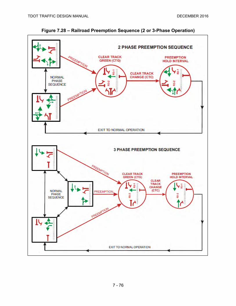
TDOT TRAFFIC DESIGN MANUAL DECEMBER 2016
7 - 76
Figure 7.28 – Railroad Preemption Sequence (2 or 3-Phase Operation)
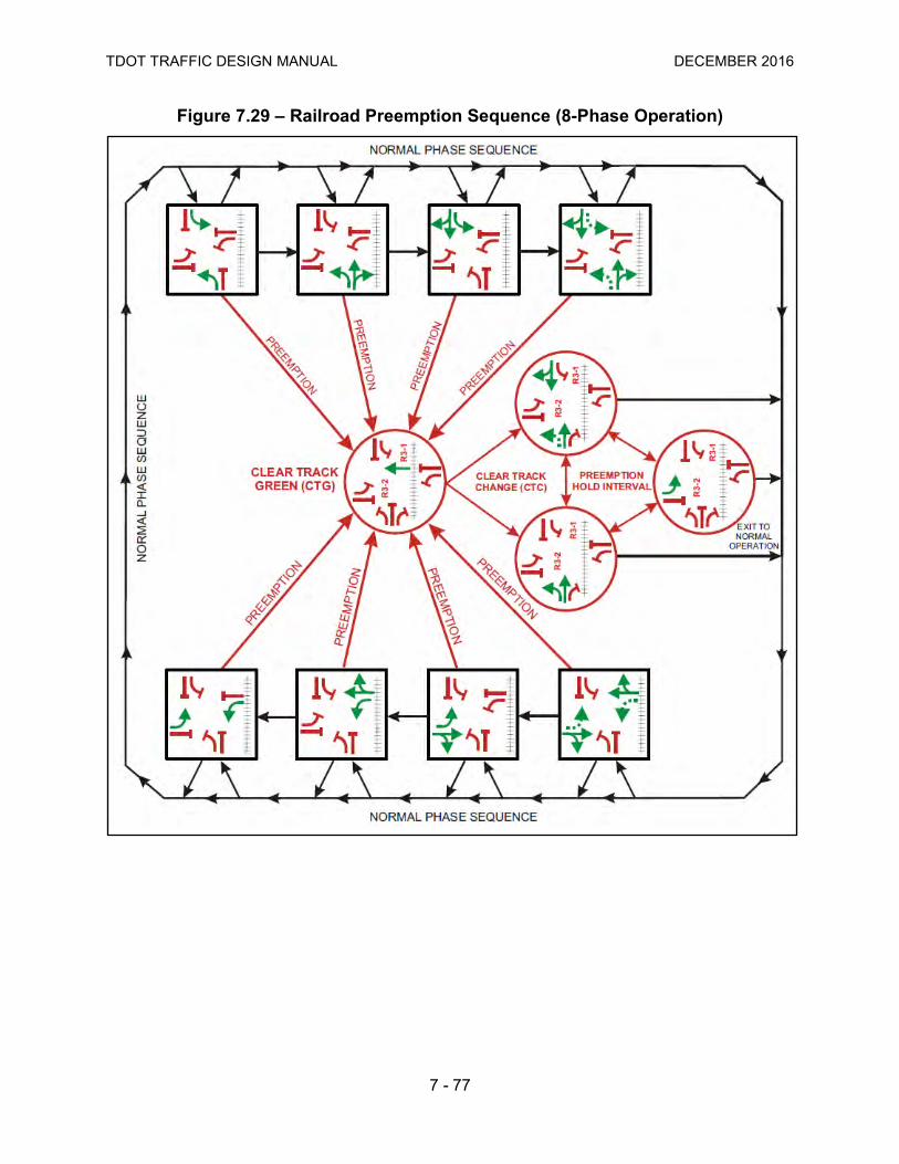
TDOT TRAFFIC DESIGN MANUAL DECEMBER 2016
7 - 77
Figure 7.29 – Railroad Preemption Sequence (8-Phase Operation)
TDOT TRAFFIC DESIGN MANUAL DECEMBER 2016
7 - 78
Railroad preemption of the traffic signal should have the following sequence:
1. A yellow change interval and any required all-red clearance interval for any signal phase that is green or yellow when preemption is initiated and which will be red during the track clearance interval. The length of yellow change and all-red clearance intervals shall not be altered by preemption. Phases which will be green during the track clearance interval and which are already green when preemption is initiated, shall remain green. Any pedestrian walk or pedestrian change interval, in effect when preemption is initiated, shall immediately be terminated and all pedestrian signal faces shall display steady don’t walk indication;
2. A track clearance interval for the traffic signal phase or phases controlling the approach which crosses the railroad tracks;
3. Depending on traffic requirements and phasing of the traffic signal controller, the traffic signal may then do one of the following:
• Go into flashing operation, with flashing red or flashing yellow signal indications for the approaches parallel to the railroad tracks and flashing red signal indications for all other approaches. Pedestrian signals shall be inactive;
• Revert to limited operation with those signal indications controlling through and left turn approaches towards the railroad tracks displaying steady red. Permitted pedestrian signal phases shall operate normally;
4. The traffic signal shall return to normal operation following the release of preemption control.
The typical information to be shown on traffic signal construction plans for railroad preemption is shown in Figure 7.30.
Railroad Preemption Turn Restrictions: According to the MUTCD Section 8B.08, a blank-out sign, changeable message sign, other similar type sign, and/or appropriate highway traffic signal indication may be used to prohibit turning movements toward the highway-rail grade crossing during preemption. A blank-out sign displays a blank face unless internally illuminated upon activation, showing the message/symbol No Left Turn (R3-2) or No Right Turn (R3-1). Blank-out signs are useful as part of the railroad preemption sequence at signalized intersections immediately adjacent to grade crossing. At these locations, turn prohibition blank-out signs can prevent traffic from turning into and occupying the limited storage area between the tracks and the intersection, and eventually blocking the intersection itself. These signs are activated upon initiation of the railroad preemption and deactivated after the preemption is completed.

TDOT TRAFFIC DESIGN MANUAL DECEMBER 2016
7 - 79
Figure 7.30 – Railroad Preemption Design Example
TDOT TRAFFIC DESIGN MANUAL DECEMBER 2016
7 - 80
Railroad Preemption Terminology: Railroad preemption signal timing design includes the calculation and programming of minimum warning time, constant warning time, equipment response time, minimum time, clearance time, buffer time, advance preemption time, total approach time, etc. For additional information regarding railroad preemption, refer to the Traffic Signal Timing Manual.
7.10.3 Multiple Preemption A combination of railroad, emergency preemption, and priority control is allowed at an intersection. There is usually a hierarchy in determining which preemption and/or priority occurs first when more than one is received by the traffic signal controller. The traffic signal controller preemption priority hierarchy shall be as follows:
1. Railroad Train Preemption; over 2. Emergency Vehicle Preemption (Fire, Rescue or Ambulance); over 3. Law Enforcement Vehicle Preemption; over 4. Light Rail Priority; over 5. Bus Priority.
7.11 Flashing Operations All traffic signals are programmed to operate in the flash mode for emergencies. Signals may also operate in maintenance flash, railroad preemption flash, or scheduled operational flash modes. The type of flash used (all-red or yellow-red) must be considered carefully. Driver expectation is an important factor. Drivers are conditioned to react to situations through their experiences. Mixing the types of flash can confuse drivers if they are accustomed to the all-red flash. The benefits of operating a mixed-color flash must be weighed against the disadvantages. Violation of driver expectation can be a disadvantage of a mixed-color flash. Flashing operations of a traffic signal shall comply with MUTCD Sections 4D.28, 4D.29, 4D.30 and 4D.31.
7.11.1 Types of Flashing Operation Flashing mode operation can be characterized by planned and unplanned operation. More specifically: Emergency Flash: Emergency flash mode is used when the conflict
monitor (malfunction management unit) senses a malfunction. Emergency flash shall use all-red flash exclusively.
Maintenance Flash: Maintenance flash mode can be programmed for the operation of the intersection during routine maintenance. Yellow-red flash can be used if the main street traffic is significantly more than the minor street traffic.

TDOT TRAFFIC DESIGN MANUAL DECEMBER 2016
7 - 81
Scheduled Flash: Traffic signals can operate in scheduled flash mode as a time-of-day operation (e.g. nighttime flash). Nighttime flash can reduce delay at intersections operating in the fixed time mode. Scheduled flash mode typically uses the yellow-red flash type operation. Nighttime flash should not be used at fully actuated intersections unless all other intersections in the area operate nighttime flash. Again, driver expectation is a major factor in this decision. Isolated actuated traffic signals do not normally have a programmed flash mode operation. If a traffic signal using LED indications is placed in an automatic flashing mode during the night, the LED signal indications should be dimmed to reduce the brightness of the indications.
Railroad Preemption Flash: When a traffic signal is preempted by a train, flashing operation may be used while the train is going through the crossing. Either all-red flash or yellow-red flash can be used.
7.11.2 Flashing Operation Signal Display The following describes the all-red and the yellow-red flashing operation: All-Red Flash: This type of flashing operation flashes red to all
intersection approaches. It may be used under the following conditions:
• Traffic Volumes: Traffic volumes on the two intersecting streets are approximately equal.
• Minor Street Delay: Minor street traffic would experience excessive delays and/or hazard in trying to cross the major street with yellow flashing signal indications. Engineering judgment must be used to balance this benefit against the delay that will be experienced by the major street traffic.
• Minor Street Sight Distance: Minor street traffic has insufficient sight distance to safely enter or cross the major street with yellow flashing signal indications.
Yellow-Red Flash: This type of flashing operation is the most common and flashes yellow to the major street and red to the minor street. Minor street sight distance, as well as the difficulty the minor street traffic will have crossing the major street, must be considered.

TDOT TRAFFIC DESIGN MANUAL DECEMBER 2016
7 - 82
[This page intentionally left blank.]