
Chapter 6. Property-process relationships in nuclear fuel ...
21
NEA/NSC/R(2015)5 Chapter 6. Property-process relationships in nuclear fuel fabrication V. Tikare Sandia National Laboratories, US Abstract Nuclear fuels are fabricated using many different techniques as they come in a large variety of shapes and compositions. The design and composition of nuclear fuels are predominantly dictated by the engineering requirements necessary for their function in reactors of various designs. Other engineering properties requirements originate from safety and security concerns, and the easy of handling, storing, transporting and disposing of the radioactive materials. In this chapter, the more common of these fuels will be briefly reviewed and the methods used to fabricate them will be presented. The fuels considered in this paper are oxide fuels used in LWRs and FRs, metal fuels in FRs and particulate fuels used in HTGRs. Fabrication of alternative fuel forms and use of standard fuels in alternative reactors will be discussed briefly. The primary motivation to advance fuel fabrication is to improve performance, reduce cost, reduce waste or enhance safety and security of the fuels. To achieve optimal performance, developing models to advance fuel fabrication has to be done in concert with developing fuel performance models. The specific properties and microstructures necessary for improved fuel performance must be identified using fuel performance models, while fuel fabrication models that can determine processing variables to give the desired microstructure and materials properties must be developed. Introduction The purpose of a nuclear fuel is to generate heat, which can be used to do work. Thus, the primary function that a nuclear fuel is required to perform is to generate heat in a controlled and sustainable manner and transfer it to power generating facility. In addition, this power generation must be done safely and economically. These basic requirements translate to surprisingly few materials performance requirements for fuels: • The density of fissionable nuclei must be sufficiently high to sustain a controlled chain reaction. 123
Transcript of Chapter 6. Property-process relationships in nuclear fuel ...

NEA/NSC/R(2015)5
Chapter 6.
Property-process relationships in nuclear fuel fabrication
V. Tikare Sandia National Laboratories, US
Abstract
Nuclear fuels are fabricated using many different techniques as they come in a large variety of shapes and compositions. The design and composition of nuclear fuels are predominantly dictated by the engineering requirements necessary for their function in reactors of various designs. Other engineering properties requirements originate from safety and security concerns, and the easy of handling, storing, transporting and disposing of the radioactive materials. In this chapter, the more common of these fuels will be briefly reviewed and the methods used to fabricate them will be presented. The fuels considered in this paper are oxide fuels used in LWRs and FRs, metal fuels in FRs and particulate fuels used in HTGRs. Fabrication of alternative fuel forms and use of standard fuels in alternative reactors will be discussed briefly. The primary motivation to advance fuel fabrication is to improve performance, reduce cost, reduce waste or enhance safety and security of the fuels. To achieve optimal performance, developing models to advance fuel fabrication has to be done in concert with developing fuel performance models. The specific properties and microstructures necessary for improved fuel performance must be identified using fuel performance models, while fuel fabrication models that can determine processing variables to give the desired microstructure and materials properties must be developed.
Introduction
The purpose of a nuclear fuel is to generate heat, which can be used to do work. Thus, the primary function that a nuclear fuel is required to perform is to generate heat in a controlled and sustainable manner and transfer it to power generating facility. In addition, this power generation must be done safely and economically. These basic requirements translate to surprisingly few materials performance requirements for fuels:
• The density of fissionable nuclei must be sufficiently high to sustain a controlled chain reaction.
123
NEA/NSC/R(2015)5
• High thermal conductivity is necessary to transfer the heat from the fuel to the power generation systems.
• Radioactive materials that are inherent to the fuel as well as those generated during fission must remain safely sequestered within the fuel.
• The cost of the complete fuel life cycle, from fabrication to disposal or reuse, must be economically comparable to competing energy technologies.
In compliance with these materials requirements, a number of nuclear fuel forms have been developed. The overwhelming majority of the nuclear fuels is UO2 in the form of fuel pellets in zircaloy clad used in LWRs. Other major nuclear fuels are UO2 fuel for fast reactors, mixed UO2 and PuO2 called MOX for use in both LWRs and FRs, metal fuels for use in FRs, particulate fuels and many other specialty fuels. In this work, the fabrication of these fuel forms will be described. The engineering properties that dictate optimisation of the fabrication process to achieve them will be reviewed. Finally, improved processing and fabrication technologies will be suggested.
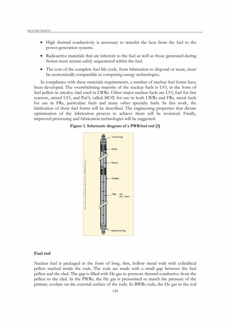
Figure 1. Schematic diagram of a PWR fuel rod [1]
Fuel rod
Nuclear fuel is packaged in the form of long, thin, hollow metal rods with cylindrical pellets stacked inside the rods. The rods are made with a small gap between the fuel pellets and the clad. The gap is filled with He gas to promote thermal conductive from the pellets to the clad. In the PWRs, the He gas is pressurised to match the pressure of the primary coolant on the external surface of the rods. In BWRs rods, the He gas in the rod
124

NEA/NSC/R(2015)5
is slightly pressurised to maintain good contact between the pellets and the clad. A schematic diagram showing a PWR rod is shown in Figure 1 [1]. The UO2 cylindrical pellets are approximately 1 cm in height and 2 cm in diameter. The clad is zircaloy with typical composition of 98% Zr alloyed with other additives. The choice of zircaloy for the clad is due to chemical stability in the boiling water in BWR and pressurised steam in PWRs. It is also highly resistance to irradiation damage and maintains it structural and dimension properties under the conditions encountered in LWRs. The clad is formed by hot and cold rolling to form a continuous long hollow tube. The ends are welded with plugs to contain the fuel pellets and fission products especially fission gases that are generated during service.
In sodium-cooled fast reactors, the geometry of the rod is similar to that of LWRs, however; there are substantial differences. The rod is thinner to accommodate the fuel pellets, which are still cylindrical, but have a smaller diameter of 0.5 cm. The clad have been traditionally made of stainless steel as it has good chemical stability when in contact with the molten sodium coolant; however other alloys and materials are sometimes used today. Again, the rod is manufactured with a gap between the fuel pellet and clad with a He gas filling it. The clad is discussed in another section of this report. The fuel pellets are the topic of this section. Their fabrication will be discussed in detail for the remainder of this section.
Figure 2. Numerous minerals contain uranium are found in many parts of the world uranium mining and UO2 powder processing
The first step in making UO2 is the mining of uranium minerals, which comes in many different types; some are shown in Figure 2. Of these minerals a few qualify as uranium ores as their content is sufficiently high and chemical structure is such as to enable economical extraction. Among these uraninite, pitchblende and davidite are the primary ores used for uranium extraction [2]. Uranium is extracted from the crushed ores by chemical extraction and refining to form yellowcake, a coarse powder with 70 to 90% U3O8 and some UO2 and UO3. The next step is to convert the yellow cake to UF6 by a series of chemical processes schematically summarised in Figure 3 [3]. UF6 is used in uranium processing because it exists in all three phases at pressures and temperature that are common to industrial processes. In the gaseous form, it can be enriched to the desired
125

NEA/NSC/R(2015)5
content of 235U. In the liquid form it can be filled and emptied from shipping containers and it can be stored as a solid.
Fuel fabrication for nuclear reactors typically begins with receipt of enriched uranium hexafluoride (UF6) from an enrichment plant. The UF6, in solid form, in containers, is heated to gaseous form, and the UF6 gas is chemically processed to form uranium dioxide (UO2) powder. Conversion of UF6 to UO2 can be performed by one of three processes. In the first, UF6 is reduced and hydrolyzed to UO2 using hydrogen and steam. In the second, UF6 is hydrolysed by solution in water, ammonia is added to precipitate ammonium diuranate, and the diuranate is reduced to UO2 with hydrogen at 820°C. In the third process, gaseous UF6, CO2, and NH3 are combined in water, precipitating ammonium uranyl carbonate. The ammonium uranyl carbonate is combined with steam and hydrogen at 500-600°C to yield UO2. UF6 to UO2 conversion is often performed as the first stage of a fuel fabrication plant [4].
Figure 3. A schematic diagram showing the conversion of yellow cake to UF6
Uranium dioxide pellet processing
Once the powder is made, standard powder compaction and sintering methods are used to make the fuel pellet. The UO2 powder is either crushed or agglomerated to obtain the optimum size distribution for die filling and pressing. The powder is uniaxially cold pressed to form a cylindrical pellet. Next the pressed pellet is sintered in a reducing atmosphere at temperatures around 1 5000C, but can be as high as 1 7000C, for approximately four hours. Finally, the pellet is machined to have a disc shaped volume removed from both ends and the edges are ground to be smoothly chamfered as shown in Figure 4. Note the shape shown in Figure 4 is an example, the final dimensions vary depending on the reactor design and fuel used in it. Some pellets are also ground to have an hour glass shape shown in the same figure. While this process appears simple, the variations are numerous to give improved performance during service in a reactor. The details of the process variations will be elaborated in this section.
126

NEA/NSC/R(2015)5
Figure 4. An LWR fuel pellet with discs removed from the ends and chamfered along the edges and materials removed to form a slight hour-glass shape along the cylindrical axis
LWR fuel pellets, UO2 fuel pellets
Among the four criteria list at the beginning of this document, density of fissile isotopes, thermal conductivity, retention of radioactive materials and cost, the one that is most influenced by UO2 pellet processing is the retention of fission gases and products. Sustaining a chain reaction is controlled by enrichment and reactor design; thermal conductivity is relatively low in UO2 especially with the presence of pores and other defects and can only be influenced slightly by processing. Thus, the primary focus of pellet processing is to optimise the microstructure to retain fission gases and other fission products while reducing porosity to improve thermal conductivity and reducing swelling to maintain structural integrity of the clad.
The fission gas release mechanism is a combination of diffusion of the gas atoms to the grain boundaries followed by a percolating event that release the gas into the gap between the fuel pellets and the clad. Fission and the subsequent decay results in formation of some Xe, Kr, I and other gases that contain some radioactive isotopes. These atoms are dissolved in the fuel lattice structure, but have very low solubility. Thus, they precipitate from the fuel lattice to form nano-sized bubbles within grains as well as at grain boundaries. As more gas atoms are generated, the intragranular bubbles become more numerous and grow larger. However, the gas in the bubbles is periodically re-dissolved into the fuel lattice when the passing of a high-energy fission fragment disorders the fuel lattice at the surface of the bubble. This dissolved gas re-precipitates out to form nano-bubbles, but some of it also diffuses to the grain boundaries where it forms grain boundary bubbles. As these grain boundary bubbles grow and become more numerous, they link together to form a percolating path to the external surface or a crack thus releasing the gas. For optimal retention of the fission gases, it is best to keep the gases either dissolved in the lattice or within grains as nano-bubbles.
127

NEA/NSC/R(2015)5
A secondary benefit to retaining gas in the intragranular nano-sized bubbles rather than in the larger grain boundary bubbles is that it minimises swelling of the fuel pellet. Minimising swelling of the fuel pellet is desirable as it reduces the physical and chemical interaction of the fuel with the clad. The pressure of the gas in the nano-sized bubbles is much higher than in the larger grain boundary bubbles due to the Gibbs-Thomson effect. This, in turn, means the volume occupied by the gas in nano-bubbles is much lower leading to less swelling of the fuel.
Retaining the gas with the grains is accomplished by enlarging the UO2 grains and reducing the porosity in the fuel. A simple relationship describing the fractional release of fission gas, F, is developed using a modified Booth analysis [5]:
(1)
where r is the grain size, D is the diffusion coefficient and t is time. One can see that as the grain size r increases, the release of fission gas to the grain boundaries F decreases. Simplistically, one can attribute this to the greater distance that the gas must diffuse to reach grain boundaries. The emphasis on retention of fission gases within the UO2 fuel grains has driven fuel vendors to manufacture LWR fuel pellets to have very large grains. Traditional LWR fuels were characterised by 12 to 15 mm grains. More recently, the fuels are doped with a variety of oxides to increase grain size. Grain sizes of UO2 with dopants have been reported to grow to be as large as 50 to 100 mm, unusually large grain sizes for ceramic materials. Some of the dopants that have been reported are TiO2 [6-8], V2O3 [9], NbO2 [10-12], Al2O3 [13] [14], Cr2O5 [14-17] and MgO [14]. Another consist result reported is that the density of the oxide doped UO2 is higher than that of the undoped UO2 [6]. While the exact mechanisms leading to grain growth and higher densification rates are not known, many speculate that it is due to increased diffusivity [18]. Virtually all the dopants listed above form solid solutions with UO2 in small quantities (<=0.2 to 0.3 wt%) with associated defects. At higher concentrations, they form a second, liquid phase. In some cases, the dopants at high concentrations form a second phase in the form of nano-size intragranular precipitates. The effect of additives on performance is also mixed with some finding no difference in FGR [10] [17] and other reporting decreased FGR [19].
The same diffusive mechanisms that enhance grain growth and densification also increase diffusivities of the dissolved fission gas atoms. Thus, the increase in gas retention due to the larger grain size r is off-set by the increase in diffusivity D as described by Equation 1. However, there appears to be another mechanism that is enabling gas retention in the large-grained UO2. Some of the additives, such as Cr2O3, form nano-sized precipitates within the grains. These precipitates serve as nucleation sites for fission gas bubbles. Thus, many more nano-sized bubbles form in the larger grains at the precipitates thus increasing the FG retention.
Thermal conductivity of fresh oxide fuels is low to begin with and continually decreases as burn-up proceeds. This decrease is generally attributed to the accumulation of fission products and irradiation damage in the fuel [20]. The formation of gas bubbles, both inter- and intragranular, also decrease thermal conductivity. There is little that can be done to mitigate this decrease. One of the few materials properties that can be controlled
128

NEA/NSC/R(2015)5
is the initial density of the fuel. Thermal conductivity as a function of porosity is given by the Maxwell-Eucken relationship:
(2)
Where λ is the thermal conductivity, λo is the theoretical thermal conductivity of the fully dense material, P is the fraction of porosity and β is a constant related to the geometry of the pores. Fabricating fuels of higher density will increase the thermal conductivity as shown by Equation 2. Retaining the fission gas in intragranular nano-bubbles rather than in intergranular submicron-sized bubbles will also help in maintaining higher thermal conductivity.
MOX fuel pellets
While MOX fuel pellets have not been used commercially in the US, they have been extensively used by the French commercially and researched for use in LWRs [21]. The original purpose of using MOX was to conserve and extend uranium resources. However, the discovery of many new uranium deposits coupled with improved mining techniques has resulted in unlimited supply of uranium for all practical purposes. The current purpose of MOX is to deplete the large stores of weapons-grade plutonium that have been amassed by recycling used fuel [22,23]. In the past, rather than use PuO2 fuel pellets with substantially different properties, relatively small quantities of PuO2 of ≤ 6% are mixed with the UO2 in the hope that the resulting fuel will perform similarly to traditional UO2 fuel [24,25,26]. Indeed, irradiation of the low-PuO2-content MOX in LWRs has shown very similar behaviour to that of UO2 [21,27,28]. In more recent years, much higher PuO2 content MOX, ranging up to 20% PuO2, has been studied and used successfully in LWRs. In this range, there are quantitative differences in fuel performance and behaviour, however, qualitatively these high-PuO2 MOX fuels behave similarly to the low-PuO2 MOX fuels [29].
PuO2 has the same crystal structure as UO2 with comparable lattice parameters. Thus the two compounds form a complete solid solution. MOX can be fabricated by co-precipitation or by mixing the two powders with the later being more, however, virtually all MOX fuel is produced by mixing the two powders. The MIMAS (MIcronized MASter blend) process is one process used for mixing UO2 and PuO2 powder in two different mixing steps. In the first step, PuO2 and UO2 powders and sintered scraps of UO2 are ball milled for several hours to obtain a homogeneous mixture. The amount of Pu concentration in the master mix can vary between 20 and 40 mol% of heavy metal, but is typically 30 mol%. The second step consists of blending the master mix with depleted or natural UO2 to obtain the desired final enrichment [30]. This process results in a heterogeneous distribution of Pu and U, as shown in Figure 5 [31] showing Pu rich region consisting of ~30% Pu, U-rich areas of almost 100% U and the “coating” region where interdiffusion has resulted in region with ~5% Pu.
Another process used to produce MOX is SBR, Short Binderless Route. In this process, PuO2, UO2, and possibly sintered scraps are assembled with the desired enrichment and milled in an attritor mill [30]. Like MIMAS, SBR also results in fuel with PuO2-rich regions, but these regions are small with PuO2 enrichment being only
129

NEA/NSC/R(2015)5
marginally more than the matrix [30]. Powders prepared by MIMAS or SBR are pressed and sintered under the same conditions used for fabricating traditional UO2 fuel.
Figure 5. The distribution of U and Pu in MIMAS MOX fuel
LWR oxide fuels are made using standard powder processing techniques. Powders are milled, mixed, sieved and combined with sintering aids. The powders are formed by uniaxial, cold, dry pressing into pellets. The pellets are sintered at approximately 1 6000C for 1 to 4 hours to the desired density. Finally, the pellets are machined to have the final shape, a haystack shaped-pellet which mitigates the mechanical interaction with the clad due to swelling.
While processing a monolithic piece of UO2 or MOX to the approximate pellet shape and desired density is routine and relatively easy with present-day technology, obtaining the exact dimensions, and matching the microstructure and composition to performance properties remains challenging. The ability to sinter the pellet to the desired end shape to minimise or even eliminate grinding the pellet to the final shape and size would simplify the processing greatly. Near-net shaping to eliminate grinding can be achieved by developing predictive modelling enabled by experiments that characterise sintering as a function of the starting powder characteristics (particle size and shape distributions, and composition and composition distribution), the powder compact characteristics (density variation in the compact after pressing). Near net shaping is routinely achieved in many metallic products as sufficient control can be exerted over all aspects of powder processing. For LWR fuels, the feed stock materials for synthesising powders can vary greatly. Thus, more research is needed to develop near-net shape sintering.
Like almost all engineering materials, the microstructure and composition of the materials must be optimised to obtain the desired performance properties during service. Nuclear fuels are no exception. The exact role of additives on diffusion processing during sintering and irradiation is not well understood. The role of precipitates on fission gas retention is also not well understood. The distribution of phases and composition on
130

NEA/NSC/R(2015)5
MOX performance is poorly understood. The bulk of the research necessary in fuel fabrication is not the fabrication itself, but in identifying the desired microstructure, phases and composition; then developing the powder processing methods to obtain this microstructure at the end of powder synthesis, pressing and sintering.
Fast reactor oxide fuel pellets
The neutronics of a fast reactor require that the fuel pellet have a smaller diameter approximately 0.5 cm as compared to the 1 cm diameter of LWR fuel pellets. While this does not have great implications for pellet processing, it does require slightly better control during the powder compaction as the aspect ratio of the die is higher. Otherwise, the basic pressing and sintering of FR pellets is very similar to LWR fuel pellets.
Another requirement imposed by FR neutronics is that enrichment of FR fuels have much higher enrichment with typical enrichments of 19% and some research fuels having PuO2 of 44% [32]. This does complicate powder processing as the higher alpha-emissions do charge the powders more, but more controlled powder processing can overcome these complications easily.
The conditions that the fuel pellet experiences in a fast reactor are substantially different from those experienced by LWR fuels. Both the absolute temperature and the temperature gradients in a FR fuel pellet are much higher. This leads to substantial restructuring of the fuel within a couple of days of service in-reactor. The fresh fuel pellet has uniform grain size and density, but very quickly becomes restructured to have the features shown in Figure 6 [28,29]. The porosity in the central portion of the pellet diffuses up the temperature gradient due to the Soret effect. It forms a central void that traverses the length of the entire pellet. In the region immediately adjacent to the void, grain growth under the large temperature gradient results in columnar grains. The third region experiences equi-axed grain growth. The outer most region remains unchanged as the temperature is low. However, at high burn-up >70 GWD/tU, the high-burn-up rim structure does form in 238U containing fuels.
Figure 6. Fast reactor fuels restructure to form a central, axial pore with grain structure as shown schematically on the left and in a micrograph on the right
Fission gas retention in FR pellets is difficult to achieve. In the central region of the fuel where the columnar grains form, the fission gas like the gas in the pores diffuses up the temperature gradient to the central void and is released. In the next layer where the
131

NEA/NSC/R(2015)5
equi-axed grains form, the temperature is high and fission gas diffusivity is high, leading to a release by diffusion to grain boundaries, followed by percolation along the boundaries. In the outer, cooler region fission gas is retained much like it is in LWR fuels.
Thus the goals of the FR fuel pellet processing to optimise performance are different than that of LWR fuel pellets. Oxygen retention within the fuel is more important than it is for LWR fuels. Each fission event removes a U atom from the UO2 lattice, leaving two oxygen atoms available to nominally oxidise the steel clad. Oxidation of the clad would substantially degrade the chemical and mechanical properties of the clad making it more susceptible to releasing radio-nuclides. In order to retain the oxygen atoms release by fission in the fuel, FR fuels are made with oxygen hypo-stoichiometry UO2-x with x ranging from 0.03 to 0.08. Hypo-stoichiometry is achieved primarily by sintering the UO2 pellet in highly reducing environments. In LWR fuels, oxygen can and does diffuse to oxidise the clad. However, far fewer oxygen atoms are released as the enrichment in LWRs fuels is much lower. The lower temperatures in the fuel and especially at the clad result in lower oxygen diffusion rates. Lower diffusivity of fewer oxygen atoms leads to less oxidation of the clad. Thus, little effort is made to lower the oxygen stoichiometry of LWR fuels.
Reducing the fuel-clad mechanical interaction by reducing fuel pellet swelling is another goal of FR fuel design. As discussed above, the high temperatures and high-temperature gradients of the fuel lead to very little retention of fission gases within grains either in the form of dissolved gas or nano-sized bubbles. While nano-sized intragranular bubbles do form, they retain much less fission gas than in LWR fuels [35]. Thus, unlike LWR fuels, no attempt to trap gas bubbles at metal oxides precipitates in large-grained structures is made. Rather the fuel rod is designed with a large plenum to retain the fission gas rather than allow it to pressurise the clad by filling the gap between the fuel pellets and clad. The plenum is normally very long, typically the same height as the core and can be located either above or below the core [36].
Due to the high neutron absorption cross-section of Pu in the fast neutron energy spectrum and the high enrichment necessary for FR, mixed UO2 and PuO2 MOX is frequently used. Unlike LWR MOX fuel, FR MOX has a much higher fraction of Pu. Other compositional differences in FR fuels may be driven by the need to consume TRU elements such as Np, Cm and Am formed during irradiation. The separation and use of these long-lived TRU elements would not only provide energy, but also reduce the burden of sequestering them for many thousands of years or even longer. While sintering of FR UO2 or MOX fuel with minor quantities of NpO2, AmO2, and CmO2 is not substantially different than the standard process of milling, mixing, pressing and sintering, some complications may arise. Achieving hypo-stoichiometry in FR oxide fuels with TRU may require some modification to the sintering process such the composition of the reducing atmosphere used during sintering. The differences in diffusivities due to TRU additions may drive the development of a modified time-temperature cycle. The TRU elements, particularly Am, have high volatility. This requires modification either to the sintering cycle or the furnace to control the loss of the TRU elements.
Fast reactor oxide fuels operate at very high temperatures with the centreline temperature that is close to its melting point. These high temperatures drive microstructural evolution and compositional changes that is specific to the fuel and design.
132

NEA/NSC/R(2015)5
There is little one can do to effect these changes during service by fabrication. Thus, the opportunity to develop improved FR oxide fuel and the attending fabrication methodologies is limited.
Metallic fuels
Metallic fuels have been used in SFRs and offer some advantages over oxide fuels. The primary one being the higher thermal conductivity of the fuel which allows the operational temperatures to be lower and requires less cooling under accident conditions. Other advantages are high fissile and fertile density capability and low Doppler broadening yielding lower reactivity feedback. However, metal fuels do have the disadvantage of having lower melting temperatures and high chemical interaction with the clad than do oxide fuels.
For optimal performance and safer operation during off-normal or accident condition, high melting temperature is desired. Alloying with components that do not lower the melting temperature of uranium and plutonium is important. Another necessary property of the alloying component is that it does not moderate the neutrons. Early attempts to alloy with iron [37-39], cobalt [40,41], aluminum [42,43] and other metals proved unsustainable [44]. Alloying with zirconium [45,46] proved to be the best option as it has the desirable neutronic properties, has a much higher melting temperature than those of Pu and U and mitigates chemical interaction with the clad. It also has the advantage of stabilising the desired phase in Pu [44,42]. A possible route for disposition of many of the long-lived TRU elements such as Np, Cm and Am, is to alloy them with U-Pu-Zr fuel. While little data exists for Cm, all other TRU elements, Am, Pu and Np, have higher vapour pressure than U at fabrication temperatures. Americium in particular has a very high vapour pressure [47]. Their high volatility present some challenge during fabrication. Another complication of alloying TRU elements with U-Pu-Zr is that they are gamma emitters; thus requiring greater shielding during fabrication and handling during and post-service.
Metal fuels for FR have traditionally been fabricated by melting and casting into long pins which are clad in stainless steels with sodium filling the gap between the fuel and clad. The fuel rod is designed with a large plenum to retain fission gas released during operation. A number of methods have been used to fabricate the metal pins. Several molten metal casting techniques, continuous casting, centrifugal casting, injection casting, vacuum casting [48,49] and others [50], have been attempted. Other methods such as co-extrusion with clad and hot rolling have also been tried. Injection casting into quartz molds has emerged as the primary fabrication of metal fuels. Injection casting of U-Pu-Zr fuels consists of melting the feedstock in the desired alloy ratio at a temperature of approximately 1 500oC in an induction furnace. To fabricate EBR-II fuel, Y2O3 coated graphite crucibles were used for the melt. Once the fuel is molten, the atmosphere in the furnace is evacuated and the quartz molds were lowered into to the melt until they were fully submerged. After several seconds when the molds have preheated, the furnace was rapidly pressurised with argon gas to inject the metal into the molds [47].
This injection casting technique has proven effective in making the long, thin metal pins with uniform isotropic microstructure that is desired. Furthermore, it is conducive to remote operation as it is easily built and operated. However, the need for retaining highly volatile components such as Am during casting is driving development of improved
133
NEA/NSC/R(2015)5
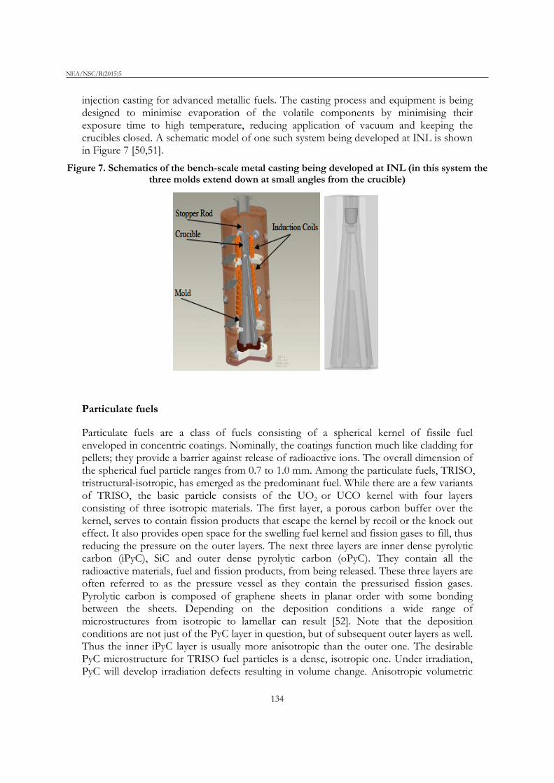
injection casting for advanced metallic fuels. The casting process and equipment is being designed to minimise evaporation of the volatile components by minimising their exposure time to high temperature, reducing application of vacuum and keeping the crucibles closed. A schematic model of one such system being developed at INL is shown in Figure 7 [50,51].
Figure 7. Schematics of the bench-scale metal casting being developed at INL (in this system the three molds extend down at small angles from the crucible)
Particulate fuels
Particulate fuels are a class of fuels consisting of a spherical kernel of fissile fuel enveloped in concentric coatings. Nominally, the coatings function much like cladding for pellets; they provide a barrier against release of radioactive ions. The overall dimension of the spherical fuel particle ranges from 0.7 to 1.0 mm. Among the particulate fuels, TRISO, tristructural-isotropic, has emerged as the predominant fuel. While there are a few variants of TRISO, the basic particle consists of the UO2 or UCO kernel with four layers consisting of three isotropic materials. The first layer, a porous carbon buffer over the kernel, serves to contain fission products that escape the kernel by recoil or the knock out effect. It also provides open space for the swelling fuel kernel and fission gases to fill, thus reducing the pressure on the outer layers. The next three layers are inner dense pyrolytic carbon (iPyC), SiC and outer dense pyrolytic carbon (oPyC). They contain all the radioactive materials, fuel and fission products, from being released. These three layers are often referred to as the pressure vessel as they contain the pressurised fission gases. Pyrolytic carbon is composed of graphene sheets in planar order with some bonding between the sheets. Depending on the deposition conditions a wide range of microstructures from isotropic to lamellar can result [52]. Note that the deposition conditions are not just of the PyC layer in question, but of subsequent outer layers as well. Thus the inner iPyC layer is usually more anisotropic than the outer one. The desirable PyC microstructure for TRISO fuel particles is a dense, isotropic one. Under irradiation, PyC will develop irradiation defects resulting in volume change. Anisotropic volumetric
134

NEA/NSC/R(2015)5
changes will crack the PyC layers, but isotropic PyC with uniform and dense microstructure will remain protective under irradiation [53]. The SiC layer, like all the layers, is chemically deposited. A “good” SiC layer is dense, equi-axed (as opposed to columnar) and small-grained with no defects such as pores or inclusion.
The variations in TRISO are the exact composition and size of the kernel. The most common kernels are either UO2 or UCO, however, other fissile materials can also be used to form the kernel, such at MOX or oxides with other transuranics. The size of the kernel can range from 350 to 500 mm and the exact thickness of the outer layers can also vary with typical layer being 35 to 90 mm thick.
These particles can be packed in various configurations to constitute a fuel element. The two most widely used are pebbles in a pebble bed reactor and fuel compacts in prismatic, graphite fuel elements. These are schematically shown in Figures 8a and b. The fuel in Figure 8a was a TRISO product developed by Pebble Bed Modular Reactor, Pty. Ltd. [54]1. The fuel element, called a pebble, is a sphere approximately the size of a tennis ball. The pebble consists of fuel particles embedded in a graphite matrix which is ~5 cm in diameter surrounded by another cm of fuel free graphite for a total pebble diameter of 6 cm. The number of fuel particles in each pebble is on the order of 15 000.
Figure 8a. Schematic of a TRISO particle in a graphite pebble
For the Prismatic Modular Reactor (PMR), the TRISO particles are embedded in a “fuel compact”, also composed of graphite matrix, which are cylinders ~5 cm in height by 1.27 cm in diameter. These cylinders are inserted into graphite fuel elements, as shown in Figure 8b [55]. Both the types of fuel elements were designed to be used in high-temperature gas-cooled reactors. He gas is used as the coolant.
Other fuel and reactor designs for particulate fuels have been proposed. These will not be reviewed here; however, one example of an alternative particulate fuel design is to use them in currently operational LWRs. The design consists of replacing current oxide pellets with pellets formed by TRISO particles dispersed in a carbon matrix. The advantages of
1 Pebble Bed Modular Reactor , Pty. Ltd. is a subsidiary of EskomHoldings and is a state of Care and Maintenance.
135

NEA/NSC/R(2015)5
this design are increased safety, higher burn-ups, reduced waste and reduced waste handling. The fission products and gases are retained in the fuel particles even under accident conditions making the fuel safer. The fuel kernels can be made of TRU fuels, thus reducing the amount of waste for disposal. The handling, transport and storage of these fuels is more robust as the fission products are hermetically sealed within each particle.
The kernel is fabricated using a sol gel process. The layers are deposited by CVD. Sol gel has been used to form spherical particles for many years [56]. Using it to form the kernel of TRISO particles was a natural extension of this technology. A sol is a dispersion of colloidal particles in a liquid. A gel is an interconnected, rigid network of long polymeric chains. The basic sol-gel process is the reaction of a nitrate salt with ammonia to produce a spherical gel. The ammonia is produced internally by the decomposition of HMTA, (CH2)6N4. An aqueous solution of uranyl nitrate is made. The active chemical reagents for UO2 internal gelation are the uranyl nitrate salt combined with urea (NH2)2CO and HMTA (CH2)6N4 inside an inert heat transfer medium, such as silicone. At the low temperature of 0oC, urea combines with the nitrate salt to stabilise the solution and prevent early gelation. The temperature is raised to 1000C and the solution is introduced into the silicone oil using a needle in the form of drops. The drops spheriodise and gelation proceeds to produce a solid sphere of hydrated uranium oxide with ammonia. The detailed process with the accompanying chemical reactions are reviewed by Jeong et al. [57]. The spheres are sintered to form the dense kernel of the TRISO particle [58,59]. The spherical kernels are coated using Chemical Vapour Deposition (CVD), to form the porous carbon, pyrolytic carbon and SiC layers over the kernel.
Figure 8b. Schematic of a TRISO particle formed into graphitic, cylindrical compacts in prismatic fuel elements
The advantage of TRISO fuel particles is that they contain the radioactive material, both the initial fissile material and the resulting fission products, within the particles. The outer layers of C and SiC serve as the containment and are often called the pressure vessel as the fission products, particularly the gases, pressurise the particle. The goal of the fabrication process is to produce highly spherical kernels and high strength, defect free coatings to ensure radioactive nuclides remain contained during service, and storage and
136

NEA/NSC/R(2015)5
transportation of the used fuel. Improved processing resulting near-perfect particles is needed. Due to criticality concerns, the kernels must be processed in small batches. Scaling fabrication operations to manufacturing scales while ensuring safety and quality of the particles is another goal.
Modelling to enable advanced fuel fabrication
A necessary component of designing fabrication methods for developing advanced fuels is to know the desired characteristics of the resulting fuel that will perform optimally during service and later during storage and/or disposal conditions. Fuel fabrication must be constantly informed by how fabrication conditions affect the resulting fuel performance. Thus, adapting and developing models for fuel fabrication must be designed under these constraints. The fuel characteristics that can be controlled by fabrication can be separated into microstructural and chemical. The chemical composition will determine the thermodynamic stability, thermomechanical properties, irradiation response and other performance characteristics. Microstructure will influence kinetic rates, release of fission products, swelling, thermal conductivity degradation and many more properties. Thus, fabrication models must be able to predict these fuel characteristics and how they evolve during fabrication.
Oxide fuel fabrication models Oxides are fabricated by pressing or otherwise shaping powder compacts that are sintered to form stronger more dense ceramics. Models that simulate these processes at multiple length scales could aid either in improving the fabrication process or the development of advanced oxides fuels. An example of the former may be the ability to make near-net shape oxides that do not require machining after sintering. Examples of the latter are when the composition of the fuel is changed by adding transuranics to UO2 or additives to control microstructure, tailoring the sintering process to ensure only the desired microstructural and compositional changes occur. This requires simulation capabilities at the microstructural and continuum scale. At the pellet-scale, engineering models that simulate the macro-dimensional size and shape changes in the powder compact from pressing to final sintering are necessary as a function of powder characteristics such as particle size and shape, particle chemical composition, additives composition and distribution, and variation in density in the pressed pellet as well as processing conditions such as die geometry, pressing variables, sintering time and temperature. At the mesoscale level, models are needed to predict microstructural evolution and variations in the composition at the grain size scale from pressed powder compact to sintering pellet. Engineering scale models of powder compaction and sintering are highly developed. Their precision to predict macroscale changes is dependent of the accuracy of the constitutive materials models they use. The development of constitutive materials models that give the shrinkage, grain growth, porosity evolution, changes in chemistry and other microstructural during oxide fabrication are the key to advancing oxide fuel fabrication modelling. Development of microstructural evolution models that can be used to obtain material models for the continuum models would be the most effective way to promote fuel fabrication.
137

NEA/NSC/R(2015)5
Metal fuel fabrication models Metal fuels are fabricated by melting the metal and pouring into to mold to cast fuel pins that have very high aspect ratios of length to diameter and must be straight. Both the casting process and models to simulate it are highly developed. Adapting these models for the geometry of materials used for metal fuel casting could be accomplished readily. Mold design and optimisation of the casting process would be most useful for metal fuel design when the geometry or composition of the fuel needs to be modified. For example, if the fuel pin requires that the porosity in the cast fuel pin should be 4% and distributed evenly through the entire length of the cast pin, the casting model can be used to bracket the casting process conditions to be tested. Such modelling would greatly reduce process development time and expense by narrowing the casting process variables to obtain the desired porosity. If the composition of the metal is changed it may change the viscosity, which, in turn, may change the metal flow and filling into the mold. Again, a casting model that can simulate pin fabrication by casting would greatly improve efficiency, cost and performance of the fuel. The investment to further metal fuel fabrication is in the adaptation of casting models to fuel geometries and materials rather than in development of the casting models themselves. Again, the emphasis should be on mesoscale microstructural models that give details of grain size and shape given cooling conditions, formation of voids given pouring conditions and other such characteristics.
Particulate fuel fabrication models Particulate fuels are fabricated by using sol-gel techniques to form the kernel and CVD is used to form the outer coatings. “Good” particles are ones that have kernels of concise size and shape with defect free coatings of even thickness with no cracks or voids. There is little that process modelling has to offer in fabricating these fuels. However, models that address the chemical and structural stability and thermomechanical performance of the particles during reactor service and later are necessary to continue to develop better designs of the particulate fuels.
Conclusion and future challenges
The fabrication of all engineering materials is intimately tied to obtaining the desired composition, microstructure and performance properties of that component. Nuclear fuels are the same. Their fabrication methods are a direct result of their performance characteristics during assembly of fuel elements, irradiation during service under normal and off-normal conditions, and during post-service handling, transportation and storage. The fabrication techniques of fuels are highly developed to meet the needs of current commercial nuclear reactors. The current fabrication processes are sufficiently advanced to enable obtaining the desired fuel macro-form with a minimal development effort. The motivation for developing improved fuel fabrication techniques for fuels in current commercial reactors is to lower cost or to improve safety and security. However, more than 50 years of LWR fuel development has optimised fuel fabrication to meet its performance requirements. Powder synthesis and powder processing have likewise continuously improved, thus oxide fuel fabrication is highly developed and not difficult to achieve. Likewise, melt and casting of metal fuels is also readily achievable with today’s technologies. Thus, the objective of improved fuel fabrication research is to develop
138

NEA/NSC/R(2015)5
fabrication techniques to obtain the desired microstructure, composition distribution and other fuel characteristics.
The ability to tailor fabrication processes and or variables with sufficient control to obtain the desired fuel characteristics is the key. The desired fuel characteristics may be large grains of UO2 with 50 nm precipitates of a particular oxide that are spaced approximately 100 nm apart. Or they may be to have Am in a metal fuel rod at a radial distance r = 0.7 (where r = 1.0 is the external surface) from the centre of the fuel axis where the temperature is relatively low, but Am is not readily able to vapourise from the surface. The fabrication variables and processes that would allow one to meet these can range from simple changes like adjusting the additives or particle size distribution to casting in a sealed furnace to very complex fabrication techniques like melt casting in layered structures to obtain the variable composition in the desired radial distributions.
A consequence of this type of fuel fabrication development to improve performance is that fuel fabrication research cannot be separated from fuel performance research. They two are closely tied thus requiring the need to design research programmes that recognise the overlap between fuel fabrication and fuel performance. This is the classic materials paradigm of fabrication-microstructure-properties link that enables progress in engineering performance of any component.
Acknowledgements
Sandia National Laboratories is a multi-programme laboratory managed and operated by Sandia Corporation, a wholly owned subsidiary of Lockheed Martin Corporation, for the US Department of Energy’s National Nuclear Security Administration under contract DE-AC04-94AL85000.
References
[1] Rudling, P. et al. (2007), Welding of Zr Alloys, IZNA7 Report.
[2] Nininger, Robert D. (1954), Minerals For Atomic Energy, Inc. New York, http://www.dangerouslaboratories.org/radore.html.
[3] http://web.ead.anl.gov/uranium/guide/prodhand/sld008.cfm.
[4] http://www.nrc.gov/reading-rm/doc-collections/cfr/part110/part110-appj.html.
[5] Booth, A. (1957), A Method of Calculating Fission Gas Diffusion from UO2 Fuel and its Application to the X-2-f Test Loop, AECL-496.
[6] Ainscough, J. et al. (1974), “The effect of titania on grain growth and densification of sintered UO2”,. Journal of Nuclear Materials, 52, 191-203.
[7] Amato, I. et al. (1966), “Grain growth in pure and titania-dopeduranium dioxide”, Journal of Nuclear Materials, 18, 252-260.
[8] Sengupta, A.K., C.B. Basak, T. Jarvis, R.K. Bhagat, V.D. Pandey, S. Majumdar (2004), “Effect of titania addition on hot hardness of UO2”, Journal of Nuclear Materials, 325, 141-147.
139

NEA/NSC/R(2015)5
[9] Amato, I., M. Ravizza (1967), “The effect of vanadium oxide additions on sintering and grain growth of uranium dioxide”, Journal of Nuclear Materials, 23, 103-106.
[10] Assmann, H. et al. (1981), “Doping UO2 with niobia beneficial or not?”, Journal of Nuclear Materials, 98, 216-220.
[11] Harada, Y. (1996), “Sintering behaviour of niobia-doped large grain UO2 pellet”, Journal of Nuclear Materials, 238, 237-243.
[12] Song, K.W., S.H. Kim, S.H. Na, Y.W. Lee, M.S. Yang (1994), “Effects of Nb2O3
addition on grain growth and densification in UO2 pellets under reducing and/or oxidizing atmospheres”, Journal of Nuclear Materials, 209, 280-285.
[13] Aybers, M. et al. (2004), “Grain growth in corundum-oxides doped uranium dioxide and effects of grain growth to the mechanical properties of uranium dioxide such as elasticity determined by ultrasonic methods”, Key Engineering Materials, 264-268, 985-988.
[14] Kashibe, S., K. Une (1998), “Effect of additives (Cr2O3, Al2O3, SiO2, MgO) on diffusional release of Xe-133 from UO2 fuels”, Journal of Nuclear Materials, 254, 234-242.
[15] Bourgeois, L. et al. (2001), “Factors governing microstructure development of Cr2O3-doped UO2 during sintering”, Journal of Nuclear Materials, 297, 313-326.
[16] Delafoy, C. et al. (2007), “AREVA NP Cr2O3-doped fuel development for BWRs”, Proceedings of the 2007 International LWR Fuel performance Meeting, San Francisco, US.
[17] Killeen, J. (1980), “Fission gas release and swelling in UO2 doped with Cr2O3”, Journal of Nuclear Materials, 88, 177-184.
[18] Une, K., I. Tanabe, M. Oguma (1987), “Effects of additives and the oxygen potential on the fission gas diffusion in U02 fuel”, Journal of Nuclear Materials, 150, pp. 93-99.
[19] Sawbridge, P.T., C. Baker, R.M. Cornell, K.W. Jones, D. Reed, J.B. Ainscough (1980), “The irradiation performance of magnesia-doped UO2 fuel”, Journal of Nuclear Materials, 95, 119-128.
[20] Ronchi, C., M. Sheindlin, D. Staicu, M. Kinoshita (2004), “Effect of burn-up on the thermal conductivity of uranium dioxide up to 100,000 MWd/t”, Journal of Nuclear Materials, 327, 58-76.
[21] Fisher, S.B., R.J. White, P.M.A. Cook, S. Bremier, R.C. Corcoran, R. Stratton, C.T. Walker, P.K. Ivison, I.D. Palmer (2002), “Microstructure of irradiated SBR MOX fuel and its relationship to fission gas release”, Journal of Nuclear Materials, 306, 153-172.
[22] http://georgewbush-whitehouse.archives.gov/omb/expectmore/summary/ 10003238.2006.html.
[23] http://www.ne.anl.gov/research/fmd/.
[24] Carbajo, J.J., G.L. Yoder, S.G. Popov, V.K. Ivonov (2001), “A review of the thermophysical properties of MOX and UO2 fuels”, Journal of Nuclear Materials, 299, 181-198.
140

NEA/NSC/R(2015)5
[25] Walker, C.T., W. Goll, T. Matsumura (1996), “Effect of inhomogeneity on the level of fission gas and caesium release from OCOM MOX fuel during irradiation”, Journal of Nuclear Materials, 228, 8-17.
[26] Sasahara, A., T. Matsumura (2008), “Post-irradiation examination focused on fuel integrity of sent BWR-MOX and PWR-UO2 fuels stored for 20 years”, Nuclear Engineering and Design, 238, 1250-1259.
[27] Bairiot, H., P. Deramaix (1992), “MOX fuel development: yesterday, today and tomorrow”, Journal of Nuclear Materials, 188, 10-18.
[28] Fisher, S.B., R.J. White, P.M.A. Cook, S. Bremier, R.C. Corcoran, R. Stratton, C.T. Walker, P.K. Ivison, I.D. Palmer (2002), “Microstructure of irradiated SBR MOX fuel and its relationship to fission gas release”, Journal of Nuclear Materials, 306, 153-172.
[29] Massih, A.R. (2006), Models for MOX Fuel Behaviour, SKI Report, ISSN 1104-1374.
[30] White, R.J., S.B. Fisher, P.M.A. Cook, R. Stratton, C.T. Walker, I.D. Palmer (2001), “Measurement and analysis of fission gas release from BNFL's SBR MOX fuel”, Journal of Nuclear Materials, 288, 43-56
[31] Oudinet, G., I. Munoz-Viallard, L. Aufore , M. Gotta, J.M. Becker, G. Chiarelli, R. Castelli (2008), “Characterization of plutonium distribution in MIMAS MOX by image analysis”, Journal of Nuclear Materials, 375, 86-94.
[32] Sengupta, A.K., K.B. Khan, Jose Panakkal, H.S. Kamath, S. Banerjee (2008), “Evaluation of high plutonia (44% PuO2) MOX as a fuel for fast breeder test reactor”, Journal of Nuclear Materials, 385, 173-177.
[33] Idemitsu, K. “Nuclear fuel engineering”, http://idemitsu.nucl.kyushu-u.ac.jp.
[34] O’Boyle, D.R., F.L. Brown, J.E. Sanecki (1969), “Solid fission product behavior in uranium-plutonium oxide fuel irradiated in a fast neutron flux”, Journal of Nuclear Materials, 29, 27-42
[35] Maeda, K., K. Katsuyama, T. Asaga (2005), “Fission gas release in FBR MOX fuel irradiated to high burnup”, Journal of Nuclear Materials, 346, 244-252.
[36] Waltar A.E., A.B. Reynolds (1981), Fast Breeder Reactors, Pergamon Press, Elmsford New York, US.
[37] Okamoto, H. (1993), “Fe-Pu (iron-plutonium)”, Phase Diagrams of Binary Iron Alloys, H. Okamoto, ed., ASM International, Materials Park, pp. 337-39.
[38] Okamoto, H. (1993), “Fe-U (Iron-Uranium)”, Phase Diagrams of Binary Iron Alloys, pp. 429-32.
[39] Kurata, M., T. Ogata, K. Nakamura, T. Ogawa (1998), “Thermodynamic assessment of the Fe-U, U-Zr and Fe-U-Zr systems”, Journal of Alloys and Compounds, 271-273, 636-40.
[40] Rough, F.A., A.A. Bauer (1958), Constitution of Uranium and Thorium Alloys, Report BMI-1300, Battelle Memorial Institute, Columbus, pp. 23.
141

NEA/NSC/R(2015)5
[41] Ellinger, F.H., W.N. Miner, D.R. O’Boyle, F.W. Schonfeld (1968), Constitution of Plutonium Alloys, LA-3870, Los Alamos Scientific Laboratory, p. 29.
[42] Ellinger, F.H., W.N. Miner, D.R. O’Boyle, F.W. Schonfeld (1968), Constitution of Plutonium Alloys, LA-3870, Los Alamos Scientific Laboratory, p. 5.
[43] Rough, F.A., A.A. Bauer (1958), Constitution of Uranium and Thorium Alloys, Report BMI-1300, Battelle Memorial Institute, Columbus, p. 11.
[44] Hecker, S.S., M. Stan (2008), Properties of Plutonium and its Alloys for Use as Fast Reactor Fuels, JNM 383.112-118.
[45] Kurata, M. (2000), Thermodynamic Assessment of the Pu-U, Pu-Zr and Pu-U-Zr Systems, Calphad, 23, 305-37.
[46] Kittel, J.H., B.R.T. Frost, J.P. Mustelier, K.Q. Bagley, G.C. Crittenden, J. Van Dievoet (1993), “History of fast reactor fuel development”, Journal of Nuclear Materials, 204, 1.
[47] Burkes, D.E., R.S. Fielding, D.L. Porter (2009), “Metallic fast reactor fuel fabrication for the global nuclear energy partnership”, Journal of Nuclear Materials, 393, 158-163.
[48] Burkes, D., R.S. Fielding, D.L. Porter, D.C. Crawford, M.K. Meyer (2009), “A US perspective on fast reactor fuel fabrication technology and experience, Part I: Metal fuels and assembly design”, Journal of Nuclear Materials, 389, 458-469.
[49] Wu, X., R. Clarksean, Y. Chen, M.K. Meyer (2002), “Design and analysis for melt casting metallic fuel pins”, International Congress on Advanced Nuclear Power Plants, Florida, US.
[50] Fielding, R., K. Marsden, B. Grover, G. Preslar (2008), “Advanced bench-scale metal fuel casting system development”, Reactor Fuels and Mat’l., Transactions of the American Nucear Society, 99, 305-306.
[51] Korzekwa, D., J. Crapps (2011), Metal Fuel Casting Simulation, LA-UR-11-05601, Los Alamos National Laboratory, US.
[52] Hunn, J.D. et al. (2008), “Increase in pyrolytic carbon optical anisotropy and density during processing of coated particle fuel due to heat treatment”, Journal of Nuclear Materials, 374, 445-452.
[53] Snead, L.L. et al. (2007), “Handbook of SiC properties for fuel performance modeling”, Journal of Nuclear Materials, 371, 329-377.
[54] http://www.pbmr. com/index.asp?Content=213&GState=Image&CatId=0&Image=44&Page=1.
[55] Sterbentz, J.W., B. Phillips, G.S. Chang, P.D. Bayless (2004), Reactor Physics Parametric and Depletion Studies in Support of TRISO Particle Fuel Specification for the Next Generation Nuclear Plant, INEEL/EXT-04-02331, Idaho National Engineering and Environmental Laboratory, US.
[56] Hench, L.L., J.K. West (1990), “The sol-gel process”, Chemical Reviews, 90, 33-72.
142

NEA/NSC/R(2015)5
[57] Jeong, K-C., S-C. Oh, Y-K. Kim, Y-W. Lee (2007), “ADU compound particle preparation for HTGR nuclear fuel in Korea”, Journal of Industrial and Engineering Chemistry, 13, 744-750.
[58] Rabu, B. et al. (2008), State-of-the-Art Transmutation Fuels and Fuel Fabrication Facilities, F16W – Contract Number 036418, PATEROS.
[59] Wegener, J.J. (2008), Production of Cerium Oxide Microspheres by an Internal Gelation Sol-gel Process, Masters Thesis, Texas, US.
143