Chapter 6 INTRODUCTION - geodesy.noaa.gov
40
Chapter 6 VERTICAL OBSERVATION (VERT OBS) DATA INTRODUCTION The purpose of this chapter is to provide detailed specifications and instructions for the coding and keying of the observation data set of a vertical control job. As was explained in Chapter 5, a vertical control job consists of two distinct data sets which must be submitted together. The companion data set to the vertical observation (VERT OBS) data set treated in this chapter is the data set containing original descriptions and/or recovery descriptions for the control points which occur in the vertical control job. This descriptive (VERT DESC) data set is treated in Chapter 7. VERT OBS DATA SET RECORDS The data wh.ich constitute a VERT OBS data set are organized into four categories: 1. Line Identification Data 2. Survey Equipment Data 3. Field Abstract Data 4. Observation Data Within these categories, the respective data have been grouped into one or more logical units called "records." A record is a string of characters containing data coded according to a specific format. Every record in a VERT OBS data set consists of 80 characters or "columns" (standard punched card image). Within each record, the 80 columns are divided into fixed-length "character fields," each field being the space reserved for a specific data item. Accordingly, for every desired data item, there exists a field of appropriate length into which the data item in question is to be entered after it 1s converted into a string of alphanumeric characters. The set of rules according to which specific data items are converted into strings of alphanumeric characters to be entered in the fields of a record is known as the "format" of ,that record. The types of records which may appear in a VERT OBS data set are listed in Table 6-1. Each type of record has been given a name, and a block diagram illustrating the respective format has been prepared to serve as a model for that record - see FORMAT DIAGRAMS. 6-1
Transcript of Chapter 6 INTRODUCTION - geodesy.noaa.gov

Chapter 6
VERTICAL OBSERVATION (VERT OBS) DATA
INTRODUCTION
The purpose of this chapter is to provide detailed specifications and instructions for the coding and keying of the observation data set of a vertical control job. As was explained in Chapter 5, a vertical control job consists of two distinct data sets which must be submitted together. The companion data set to the vertical observation (VERT OBS) data set treated in this chapter is the data set containing original descriptions and/or recovery descriptions for the control points which occur in the vertical control job. This descriptive (VERT DESC) data set is treated in Chapter 7.
VERT OBS DATA SET RECORDS
The data wh.ich constitute a VERT OBS data set are organized into four categories:
1. Line Identification Data 2. Survey Equipment Data 3. Field Abstract Data 4. Observation Data
Within these categories, the respective data have been grouped into one or more logical units called "records." A record is a string of characters containing data coded according to a specific format. Every record in a VERT OBS data set consists of 80 characters or "columns" (standard punched card image). Within each record, the 80 columns are divided into fixed-length "character fields," each field being the space reserved for a specific data item. Accordingly, for every desired data item, there exists a field of appropriate length into which the data item in question is to be entered after it 1s converted into a string of alphanumeric characters. The set of rules according to which specific data items are converted into strings of alphanumeric characters to be entered in the fields of a record is known as the "format" of ,that record.
The types of records which may appear in a VERT OBS data set are listed in Table 6-1. Each type of record has been given a name, and a block diagram illustrating the respective format has been prepared to serve as a model for that record - see FORMAT DIAGRAMS.
6-1

Except for the first and last records of the data set, the second character field of each record (columns 7-10) contains a two-digi.t numerical data code, preceded and followed by an asterisk, which specifies the of that record (*10*, *11*, ••• , *43* - see Table 6-1). The first and last records of the data set (the Data Set Identification Record and the Data Set Termination Record) display the two-character alphanumeric job code assigned by the submitting agency in this field (*Al*, *A2*, ••• , *ZZ* - see Chapter 5). The first character field of every record (columns 1-6) is reserved for the respective record sequence number - see Chapter 5. The remaining portion of each record(columns 11-80) contains character fields which are peculiar to each individual record type.
TABLE 6-1 VERTICAL OBSERVATION DATA SET RECORDS
FIRST RECORD *AA* - Data Set Identification Record
LINE IDENTIFICATION DATA *lU* - Line Information Record *11* - Line Title Record (Optional) *12* - Line Title Continuation Record (Optional) *13* - Line Title Continuation Record (Optional) *14* - Line Title Continuation Record (Optional) *15* - Comment Record (Optional)
SURVEY EQUIPMENT DATA *20* - Instrument Infonnation Record *21* - Rod Information Record *22* - Rod Standardization Record *23* - Rod Calibration Record
FIELD ABSTRACT DATA *30* - Field Abstract Record
OBSERVATION DATA *40* - Survey Equipment Record *41* - Running Record *42* - River/Valley Crossing Record *43* - Correction/Rejection Record
LAST RECORD *AA* - Data Set Termination Record
Note: The symbol *AA* denotes the two-character job code assigned by the submitting agency - see Chapter 5.
6-2

STRUCTURE OF THE VERT OBS DATA SET
The first of a VERT OBS data set must be the Data Set Identification Record which contains the required information to identify the data set and to correlate it with its companion VERT DESC data set - code, data type (VERT OBS), name of submitting agency, and date the data set was created. The last record of the data set must be the Data Set Termination Record. It is the only other record in the data set on which the respective job code appears in the same field (columns 7-10 as on the Data Set Identification Record.
The VERT OBS data set records which are bracketed by these two delimiting records may pertain to one or more units of field work; i.e., field observation data for several leveling lines may by submitted in one VERT OBS data set under the same job code, provided that the total number of survey points (bench marks and temporary bench marks) in the job does not exceed 9,999 (see Chapter 5). When two or more leveling lines are included in a vertical control job, each line must appear as a complete unit in the respective VERT OBS data set, i.e., as a block of records which contains all information pertinent to that line (see table 6-2). Each line must begin with a *10* record, contain any appropriate number of the other types of records in proper sequence, followed by one or more *40 - series records.
TABLE 6-2 STRUCTURE OF THE VERT OBS DATA SET
Data Set Identification *10*-series records *20*-series records (if *30* records *40*-series records
*10*-series records *20*-series records *30* records *40*-series records
: : : :
Record
·:]
*10*-series records :] *20*-series records (if any) *30* records *40*-series records
Data Set Termination Record
FIRST LINE
SECOND LINE
.... . . . .
LAST LINE
A leveling line is a unit of field work consisting of a number of, survey points (bench marks and temporary bench marks - see Chapter 5) which are connected by chains of differential leveling observations called "runnings." When coded as part of a VERT OBS data set, a leveling line is a block of records comprising record groups arranged in the following order:
1. Line Identification Data (*10*-Series) Records:
*10* record *11* record (optional; possibly *12*, *13*, and *14* records as
well) *15* records (optional, any number allowed)
2. Survey Equipment Data (*20*-Series) Records:·
*20* records (at least one if instrument not previously reported; in general, one for each ~reviously unreported stadia factor determination) for the first instrument used
*20* records (at least one if instrument not previously reported; in general, one for each previously unreported stadia factor determination) for the second instrument used .... . . . .
*20* records (at least one if instrument not previously reported; in general, one for each previously unreported stadia factor determination) for the last instrument used
*21*, *22*, and/or *23* record(s) - *21* record alone if rod not previously reported and no standardization or calibration data are available; in general, one *21* record followed by one or more *22* records (one for each previously unreported rod standardization), one or more •22•; *23*,•••• *23* record sets (one such set for each previously unreported single-temperature rod calibration), and/or one or more *23*, *23*,•••, *23* record sets (one such set for each previously unreported multiple-temperature rod calibration with one or more *23* record(s) for each calibration temperature) for the first rod used
*21*, *22*, and/or *23* record(s) - *21* record alone if rod not previously reported and no standardization or calibration data are available; in general, one *21* record followed by one or more *22* records (one for each previously unreported rod standardization), one or more *22*, *23*,•••, *23* record sets (one such set for each previously unreported single-temperature rod calibration), and/or one or more *23*, *23*,•••, *23* record sets (one such set for each previously unreported multiple-temperature rod calibration with one or more *23* record(s) for each calibration temperature) -
.... . . . . for the second rod used
*21*, *22*, and/or *23* record(s) - *21* record alone if rod not
6-4

previously reported anrl no standardization or calibration data are available; in general, one *21* record followed by one or more *22* records (one for each previously unreported rod standardization), one or more *22*, *23*,•••, *23* record sets (one such set for each previously reported single-temperature rod calibration), and/or one or more *23*, *23*,•••, *23* record sets (one such set for each previously unreported multiple-temperature rod calibration with one or more *23* record(s) for each calibration temperature) -for the last rod used
Note that for instruments and/or rods which are used in more than one leveling line submitted in the same or in different vertical control jobs, it is not necessary to repeat the sane *20*-series records in each such line or each such VERT OBS data set. It is sufficient to submit the respective *20*-series records once as part of the first line submitted in which such instruments and/or rods appear, and thereafter only if the stadia factor is redetermined for an instrument and/or if a rod is restandardized or recalibrated - see SURVEY EQUIPMENT DATA RECORDS.
3. Field Abstract Data (*30*) Records:
*30* records - one for the first (starting) survey point (bench mark or temporary bench mark) followed by one *30* record for each elevation carried forward to a survey point along the leveling line.
The order of the *30* records is important; normally they should follow in sequence as the respective survey points (bench marks and temporary bench marks) occur along the leveling line. However, one or more spurs may emanate from any given survey point - in which case, after the *30* record for such a "base" point, the *30* records for all survey points along the longest spur must follow first, then those along the next-longest spur, etc. Only when all spurs emanating from that base point have thus been exhausted, should the *30* record for the elevation carried forward to the next survey point along the main route be given - see example in Figure 6-1.
In the absence of any closed loops, there will be as many *30* records as there are survey points along the leveling line. However, if a loop is closed in the case of a spur loop or if the line itself forms a closed loop, an additional *30* record must appear in proper sequence (see above) for the endpoint of every such loop, reflecting the elevation carried forward to that bench mark or temporary bench mark via the •
6-5

4. Observation Data (*40*-Series) Records:
*40* record giving the date, instrument/rod combination, and collimation error data for the first set of runnings
*41* record for the first running in the first set *43* record (if needed) for the first running in the first set *41* record for the second running in the first set *43* record (if needed) for the second running in the first set
*41* record for the last running in the first set *43* record ( needed) for the last running in the first set *40* record giving the date, instrument/rod combination, and collimation
error data for the second set of runnings *41* record for the first running in the second set *43* record (if needed) for the first running in the second set *41* record for the second running in the second set *43* record (if needed) for the second running in the second set
*41* record for the last running in the second set *43* record (if needed) for the last running in the second set
*40* record giving the data, instrument/rod combination, and collimation error data for the last set of runnings
*41* record for the first running in the last set *43* record (if needed) for the first running in the last set *41* record for the second running in the last set *43* record (if needed) for the second running in the last set
*41* *43* *42* *43* *42* *43*
record record record record record record
for the last running in the last set (if needed) for the last running in the last set for the first river/valley crossing along the line (if needed) for the first river/valley crossing along for the second river/valley crossing along the line (if needed) for the second river/valley crossing along
*42* record for the last river/valley crossing along the line
line
line
*43* record (if needed) for the last river/valley crossing along line
LINE IDENTIFICATION DATA RECORDS *10* Line Information Record *11* Line Title Record (Optional) *12* Line Title Continuation Record (Optional) *13* Line Title Continuation Record (Optional) *14* Line Title Continuation Record (Optional) *15* Comment Record (Optional)
6-6

The line identification data records, bearing the *10*-series data codes, are listed above; the block diagrams illustrating the respective formats will be found under FORMAT DIAGRAtiS.
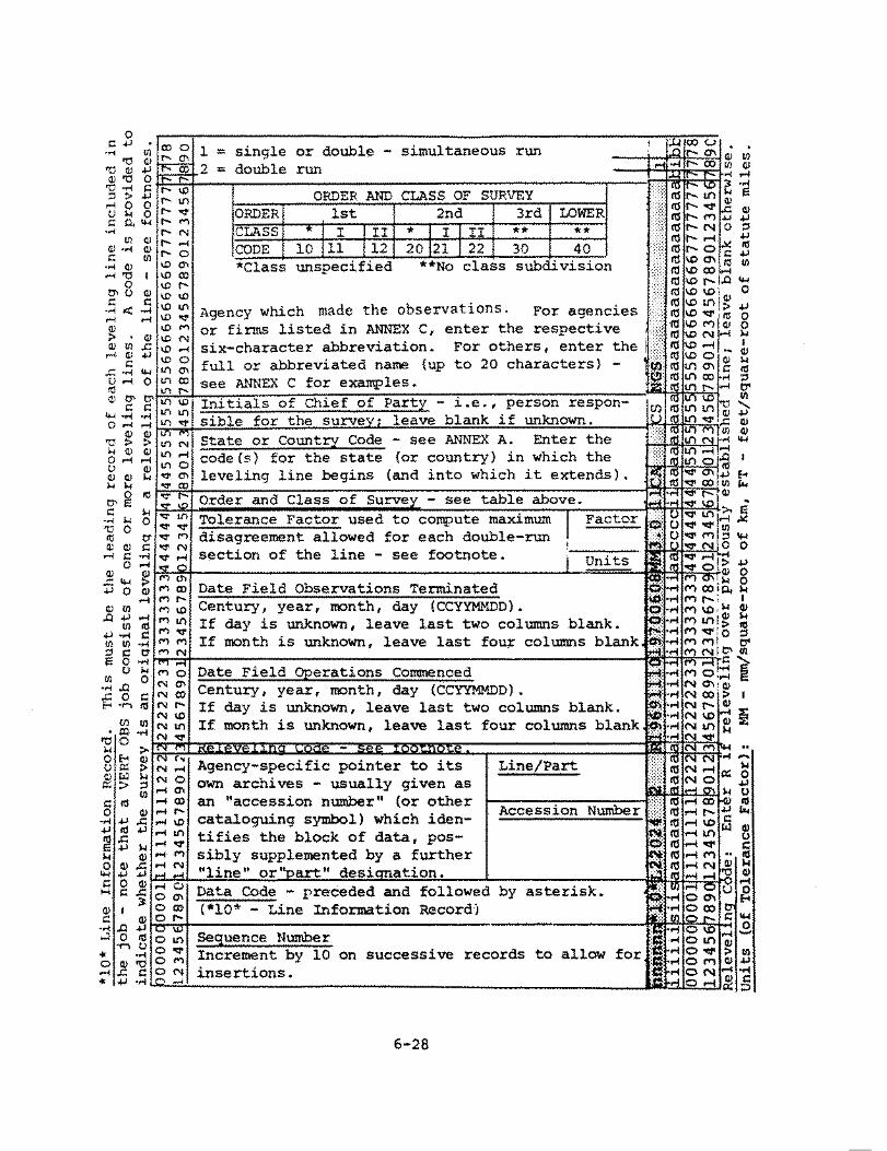
The *10* record contains essential line identification data and is always required. The *11* record is optional; however, it is highly desirable that a line title (reflecting the geographic location of the line - see below) be given. The line title should be concise so as to fit on the *11* record (up to 70 characters); however, one, two, or three continuation records (the *12*, *13*, and *14* records) may be appended if the title is lengthy or if a main title followed by subtitle(s) is called for. Following the *11* record (or else the last title continuation record), there may appear as oany *15* records as appropriate to give comments pertinent to the leveling line (e.g., significant problems encountered, deviations from standard procedures, etc.), if any.
The entries on these records (see FORMAT DIAGRAMS) are for the most part self-explanatory; however, the following data items will be explained in greater detail:
Leveling Line: As was stated in the preceding section, a leveling line is a unit of field work consisting of a number of survey points (bench marks and temporary bench marks) which are connected by chains of differential leveling observations called .. runnings." Each segment of a leveling line consisting of two neighboring survey points connected by a running is called a "section .. of the leveling line.
The objective of differential leveling is the extension of vertical control by precise determination of differences of elevation between successive survey points along the leveling line. The end product is a string of permanently marked vertical control points or bench marks (BMs).
Tolerance Factor: To control the accumulation of error in the differential leveling process, each section of a leveling line is normally "double-run," i.e., observed twice by runnings in opposite directions, and the disagreement between the respective differences of elevation as determined by the two runnings must not exceed a tolerance limit computed as the product of the appropriate tolerance factor and the square root of the section length.
Aside from the units of measurement involved, the numerical value of the tolerance factor used for this purpose depends on the type and intended accuracy of the vertical control survey in question; it is one of the specification parameters which characterizes a given order and class of vertical control survey (see below).
6-7

Note that the tolerance factor is expressed in mixed units, i.e., in "Units of Elevation-Difference Disagreement Per Square-Root of Units of Section Length." For the purposes of this publication two such unit combinations are allowed (must be specified by the respective units code given as part of the tolerance factor data group on the *10* record):
1. Millimeters per square-root of kilometers (units code MM), and 2. Feet per square-root of statute miles (units code FT).
Order and Class of Survey: A two-digit code is provided on the *10* record to specify the order of accuracy of the survey. The first digit of this code reflects the order and the second digit the class of the survey in accordance with the "Classification, Standards of Accuracy, and General Specifications of Geodetic Control Surveys," prepared by the Federal Geodetic Control Committee (FGCC), and published by the National Oceanic and Atmospheric Administration (NOAA), U.S. Department of ColllLlerce, Rockville, MD (February 1974). In addition to the five vertical control survey categories defined in this publication, three other survey categories need to be considered - old vertical control surveys of first or second order for which no class is specified, and surveys of lower-than-third-order accuracy. The respective two-digit codes are as follows:
10 - First-Order (Class Unspecified) 11 - First-Order, Class I 12 - First-Order, Class II 20 - Second-Order (Class Unspecified) 21 Second-Order, Class I 22 - Second-Order, Class II JO - '.I'I:it;:4:-0rder.
ifl'"'"(.~o - Lower-Than-Third-Order 11
The order-and-class code assigned to a leveling line should reflect the procedures and specifications according to which that entire line has been observed. When well-defined segments of a leveling line fall into different order-and-class categories, the line must be divided accordingly and the respective parts submitted as separate lines.
State or Country Code: Provision is made on the *10* record to indicate the political unit(s) and/or geographic area(s) in which the leveling line is located using the two-letter state or country codes given in ANNEX A. Up to three such codes may be entered, in the order of progress along the line in question. In the United States or in Canada, enter the appropriate code for the respective state, commonwealth, province, or territory; elsewhere enter the appropriate code for the respective country, island group, or geographic area - see ANNEX A.
6-8

Line Title: The desired elements of information in the title of a leveling line are (1) the respective line number or other identification symbol, (2) the order of accuracy of the survey, (3) whether original leveling or releveling, and (4) the geographic locality (or localities) of the survey. Since the first three elements are explicitly coded on the *10* Line Information Record (see FORMAT DIAGRAMS), it would be superfluous to repeat them in the line title, and hence only the geographic location needs to be specified. The use of geographic location alone as the title of a leveling line has traditionally been the practice of the NGS and its predecessors.
In general, the title by which the leveling line is known to the submitting agency should be given, supplemented to reflect geographic location, as required. Omit -p.1nctuation marks (periods, commas, etc.) and parentheses whenever their omission can be tolerated, and use ANNEX A state and country codes whenever reference to a state or country is necessary. Furthermore, edit and/or abbreviate the line title in the interest of fitting the entire title on the *11* Line Title Record, if at all possible. However, up to three additional records (the *12*, *13*, and *14* Line Title Continuation Records) may follow the *11* Line Title Record if the title must be lengthy or when a main title followed by one or more subtitles is desired.
The geographic location of the leveling line should be descri.ptive of the route followed, i.e., the starting locality, any prominent "via" points, and the ending locality should be specified in the order of progress of the survey (Example: ALBANY GA VIA MORVEN TO CALLAHAN FL). If the leveling line is a member of a special project or of an area network to which a specific name or title has been assigned, such a name or title should be carried as .a main title on the *11* record and the title of the line proper should follow as a subtitle on one or more of the continuation records. Example:
*11* Record: *12* Record:
DATE AND TIME
TULARE-VASCO ARVIN-MARICOPA AREA CA 9.1 KM SE OF KETTLEMAN CITY TO PIXLEY
Date of the VERT OBS data set creation must appear on the Data Set Identification Record, and the dates on which survey operations commenced and terminated are to be entered on the *10* Line Information Record. In addition, character fields are reserved for the date and/or time on several other records of the VERT OBS data set. Throughout the VERT OBS data set, date and time are to be coded as follows:
Date: date is coded as an eight-digit integer number consisting four two-digit groups denoting (from left to right) the last whole century, number of full years since the turn of century, month of the year, and day of the month (CCYYMMDD). For the 20th
6-9

century, the "century" columns may by omitted, and the date coded as a six-digit integer number denoting the year, month, and day (YYMMDD). If the day is not known (e.g., in connection with old data extracted from archives for which the date is not fully specified), leave the last two columns of the field blank; if the month is not known, leave the last four columns of the field blank. For example, February 8, 1970, would be coded as follows:
l. 2. 3.
Full date is known: Day of the month is not known: Month of the year is not known:
19700208 197002 1970
or 700208 or 7002 or 70
Time: The time of day is. coded as a four-digit integer number consisting of two two-digit groups denoting (from left to right) the hours and minutes (HHMM) of a 24-hour clock. Each four-character time field or pair of (beginning and ending) time fields is preceded by a one-character field reserved for the appropriate one-letter U.S. Navy time zone designation (see below). In every case, the local zone time is to be used; in this manner ambiguities are avoided concerning the date, which is always assumed to be the "local" date (i.e., the date changes at local midnight).
Time Zone: A time zone is a geographic region in which uniform time differing by an integer number of hours from Greenwich Mean Time (GMT) is maintained by law. In theory, a time zone extends 7-1/2 degrees in longitude east and west of a "time meridian" whose longitude is a multiple of 15 degrees (since the Earth rotates 360 degrees in 24 hours, 15 degrees of longitude difference equals one hour of time difference). In practice, the lines which separate adjacent time zones often follow political boundaries and are therefore irregular. Associated with every time zone is a "time zone description" - an integer number positive west of Greenwich and negative east of Greenwich - which represents the number of hours which must be added (algebraically) to the local zone time in order to obtain the corresponding GMT. The time zone description is reduced by one hour when the standard zone time is changed to daylight-saving time.
Instead of the numeric time zone description, it is more convenient to use the U.S. Navy one-letter codes which uniquely identify each time zone. In this system, GMT is the "Z" (Zulu) Time Zone. Time zones east of Greenwich are identified by letters A, B, C, etc., through L, with the letter J omitted. Time zones west of Greenwich are identified by letters N, O, P, etc., through X. The letter Y is used to designate the western half of the time zone centered on the meridian of longitude 180 degrees (International Date Line), and the letter Mis used to designate the eastern half of this zone.
The world-wide use of the time zone descriptions and the U.S. Navy oneletter designations is illustrated in ANNEX H. In the continental

United States, Alaska (AK), and Hawaii (HI) the time zones are as given in Table 6-3
TABLE 6-3 - U.S. NAVY TIME ZONE DESIGNATIONS
STANDARD DAYLIGHT TIME TIME ZONE U.S. NAVY TIME TIME MERIDIAN DESCIRP'N DEISGNATION
Atlantic AST Eastern EDT 60W +4 Q (Quebec) Eastern EST Central CDT 75W +5 R (Romeo) Central CST Mountain MDT 90W +6 s (Sierra) Mountain MST Pacific PDT 105W +7 T (Tango) Pacific PST Yukon YDT 120W +8 u (Uniform) Yukon YST AK/HI HDT 135W +9 V (Victor) AK/HI HST Bering BDT 150W +10 w (Whiskey)
If the time zone cannot be reliably ascertained, leave the time zone field blank. In this case, the time given will be interpreted as the standard time in a zone determined on the basis of the longitude of the vertical control point from which the respective leveling observations (running) originate. As this printing, Arizona, Hawaii, eastern Indiana, Puerto Rico, the Virgin Islands, and American Samoa do not observe daylight savings time. Verify locally (during the time of observations) whether or not daylight savings time is in effect.
SURVEY EQUIPMENT DATA RECORDS
*20* Instrument Information Record *21* Rod Information Record *22* Rod Standardization Record *23* Rod Calibration Record
The survey equipment data records, identified by *20*-series data codes, are listed above; the block diagrams illustrating the respective formats are given in the FORMAT DIAGRAMS. The survey equipment data records contain identification and calibration data pertaining to the leveling instruments and rods used to carry out the differential leveling observations. See STRUCTURE OF THE VERT OBS DATA SET for the proper sequence in which the *20*-series records must appear in the block of records which constitutes a leveling line in a VERT OBS data set.
The *20* Instrument Information Record contains the data required to identify a leveling instrument (the appropriate NGS survey equipment code. and the instrument serial number), date of stadia factor determination, and the stadia factor itself. This stadia factor will be used in the computation of the lengths of sights made with that instrument subsequent to the respective stadia factot determination date. Several *20* records may be submitted as a group for a leveling instrument; one for each past stadia factor determination.
6-11

The *21* Rod Infon,iation Record contains analogous data (the appropriate NGS survey equipment code and the rod serial nunhe.r) required to identify a leveling rod; however, it does not contain any calibration dau. Rod calibration data, which are required only for rods used in first- and second-order differential leveling work, nust follow the *21* record in the fort1 of a *22* record, a record set consisting of a *22* record and one or more *23* record(s), or a record set consisting of two or t1ore *23* records, all bearing the sar,e standardiz.Rtion/calibration date.
Again, several such *22* records, *22*, *23*,•••• *23* record sets, and/or record sets of the forn *23*, *23*,•••• *23*, as appropriate, nay be subllitted as a group for a leveling rod following the respective *21* ~od Infomation kecord; one such *22* record, *22*, *23*,•••• *23* record set, or *23, *23*,•••• *23* record set for each past calibration of the leveling rod in question.
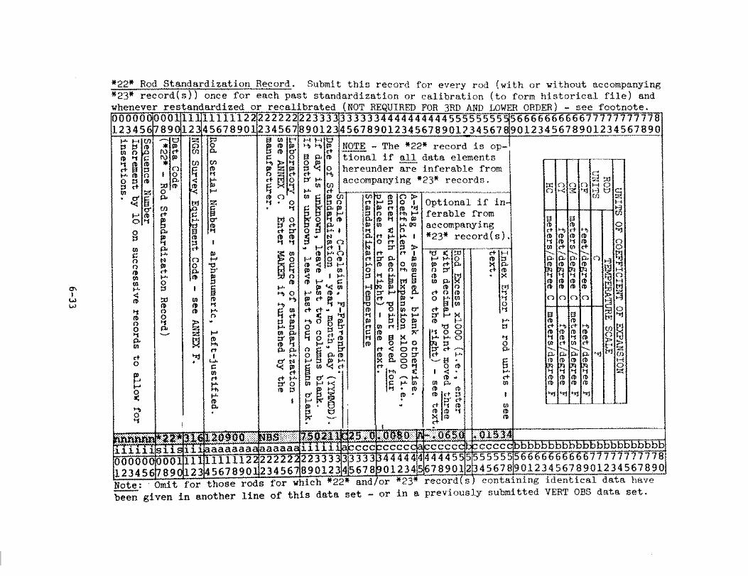
The *22* Rod Standardization Record contains the sunmary of a rod calibration. For the purposes of this chapter, the term "standardization" will be used to denote a group of data which is the end product of a rod calibration (i.e., the respective coefficient of thermal expansion, rod excess, and index error - see below). The *22•~ RoJ Standardization Record i.1ay appear alone, or it ruay be followed oy one or more *23* Rod Calibration Record(s) containing the (single-teaperature) calibration data on which the standardization summary is based, Optionally, a *22* record 11ay also precede a set of two or more *23* records of a multiple-temperature calibrationj in this case, however, all data contained on the leading *22* record.are inferable fron the accompanying *23* records.
The *23* Rod Calibration Record contains data pertaining to the calibration of a leveling rod at one temperature. For singletenperature calibrations, submit one or more *23* record(s) following the corresponding *22* record (see above) - as nany as required to accollllllodate all calibration intervals (three per *23* record - see FOR11AT DIAGRAMS). For roultiple-temperature calibrations, subrJit a set of *23* records (one or more per calibration temperature), with or without a preceding *22* record, which is optional in this case. In general, *23* Rod Calibration Records should be sub□itted whenever rhc respective data are available.
NGS Leveling lnstrunent and Rod File: The purpose of the *20*-series records is to provide -input to a permanent computer file in which a historic record is maintained for each leveling instrument and leveling rod ever used in a VERT OBS data set submitted to the National Geodetic Survey. A record 1s established in this file for an instruoent or rod at the first tice it is encountered in the processing of a VERT OBS data set. Thereafter, the file is updated by adding new information to the respective instrument and/or rod records whenever
6-12

standardization or calibration data not previously available are encountered among the *20*-series records of a subsequently processed leveling line in the same or different VERT OBS data set.
Accordingly, it is not necessary to repeat identical *20* Instrument Inforr.:iation Records among the *20*-series records of every leveling line in which that instruuent appears. It is sufficient, for any instrur:ient, to submit one or more such records (one for each past determination of the respective stadia factor) once initially, and thereafter only 1,:hen a new stadia factor is determined (e.g., following the installat:1.on of a new reticle). Of course, for each leveling line, care rnust be taken to insure that any onitted *20* Instrument Infornation Records have previously been made available for inclusion in the ncs Leveling Instrm::ient and Rod File.
Analo8ously, it is not necessary to repeat identical *21* Rod Information Rec.ords, *22* Rod Standardization Records, and/or *23* Rod Calibration Records among the *20*-series records of every leveling line in whic.h the respective rod appears. It is sufficient, for any rod, to submit an appropriate grouping of these records (covering all past calibrations) only once initialy, and thereafter only when the leveling rod in question is recalibrated. Again, in connection with every leveling line, care oust be taken to insure that any omitted *21*, *22*, and/or *23* records have previously been nade available for inclusion in the NGS Leveline Instrument and Rod File.
To suf"lmarize, sub-nit a *20* record for every previougly unreported levelinc instrument and/or previously unreported -starlia factor determination. For every leveling rod, submit a *21* record alone if the rod has not previously been reported anrl no calibration data follow (e.g •• a rod used in third- or lower-order differential leveling work exclusively). Otherwise, submit (as a group) one *21* r8cord followed by one or more *22* records, one or more *22*, *23*,•••• *23* record sets, and/or one or more *23*, *23*,•••i *23* record sets, as appropriate.; one such *22* record, *22*, *23*,•••, *23* record set, or *23*, *23*, ••• , *23* record set for each previously unreported calibration of the leveling rod in question.
tJGS Survey Equipn.ent Code: A three-digit numeric identification code assigned to each category of survey equipmentt and within each category to specific instruments or other commonly used items. In particular, leveling instruments are assigned 200-series survey equipment codes, while leveling rods and staves are assigned 300-series survey equipment codes (see ANNEX F).
Instrument/Rod Serial Number: Assigned by the manufacturer, the serial number is the ultimate identifier of a specific leveling instrument or leveling rod. Serial numbers are normally numeric;
6-13
however, alphabetic characters are often used as prefixes, suffixes, etc., and special characters such as a blank , space), hyphen (minus sign), slash (solidus), etc., may appear imbedded in the respe.ctive alphanumeric character group. For this reason, a serial number must be treated as alphanumeric information to be entered in the respective character field left-justified and blank-filled on the right.
The instrument or rod serial nunber will be used together with the respective survey equipnent code (see above) to create appropriate entries in the NGS Leveling Instrument and Rod File, to maintain these entries up to date, and to access this file for the retrieval of the respective stadia factor and/or rod calibration data in the course of routine processing of VERT OBS data sets. It is therefore of utmost importance that the respective serial number be faithfully reproduced as given by the manufacturer, character for character, including any leading zeros, imbedded blanks, etc., and that identical serial nunber representation be used consistently whenever reference is nade to that specific instrument or rod in any VERT OBS data set.
Stadia Factor: An instrument-specific constant numerically equal to the ratio of the focal length of the instrunent to the respective stadia interval, i.e., to the distance w-hich separates the stadia lines (two horizontal lines spaced equally above and below the level line) in the reticle of the leveling instrument. By design, the stadia interval is chosen so that the stadia factor is a convenient integer number such as 100.
The stadia factor is used to obtain the distance between the leveling instrument and a rod as the product of the stadia factor multiplied by the respective (full) stadia intercept - see OBSERVATION DATA RECORDS. Note that a sight length so obtained is in the same units as the stadia intercept, i.e., in rod units, and hence must be further multiplied by a conversion factor to obtain the sight length in other units.
Rod Units: The units in which the respective rod scale is graduated. Four different rod units are acceptable, each identified by a two-letter code. They are as follows:
CF - centifeet (0.01 ft) CM - centimeters (0.01 m • 1 cm) CY - centiyards· (0.01 yd= 0.03 ft) HC - half-centimeters (0.005 m = 0.5 cm= 5 mm)
Rod Graduation Code: A one-digit code denoting the type of graduation of the respective leveling rod:
1 - line graduation (single scale) 2 - line graduation (double scale) 3 - block graduation (including checkerboard) 4 - other
6-14

Temperature Scale: The teuperature at which the leveling rod was calibrated must be given on both the *22* Rod Standardization Record _(Standardization Temperaturt!) and the *23* Rod Calibration Record (Calibration Temperature). On either record. provision is made to indicate which of the two possible temperature scales applies by means of a one-letter code immediately preceding the respective temperature field:
C - Celsius Temperature Scale F - Fahrenheit Temperature Scale
Coefficient of Expansion: The relative change in linear dimension (expansion or contraction) per unit of temperature change peculiar to the material of the respective leveling rod scale (these include INVAR or other low-expansion metal alloys for modern rods. and specially treated wood for rods used in older differential leveling work of high precision). Aside froo the scale factor lOtOOO mentioned below, the coefficient of expansion given on the *22* Rod Standardization Record must be in units which are compatible with the respective temperature scale and ro<l units (see above), as specified in Table 6-4.
TABLE 6-4 UNITS OF COEFFICIENT OF EXPANSION
TE?!PERATURE SCALE ROD
UNITS C F
CF feet per degree Celsius feet per degree Fahrenheit
CM meters per degree Celsius meters per degree Fahrenheit
CY feet per degree Celsius feet per degree Fahrenheit
HC meters per degree Celsius meters per degree Fahrenheit
The coefficient of expansion expressed in either one of the four possible unit combinations (see above) is always a very small decimal fraction. To avoid the keying of a long string of zeros preceding the first significant digit, ente~ the respective coeffici~nt of expansion multiplied by 10 1000, i.e., with the decimal point moved four places to the right (Example: A coefficient of expansion of 0.00000079 is entered as 0.0079 or .0079).
6-15

A-Flag: Enter 'A' if the coefficient of expansion (see above) is an "assumed" value (i.e., as given by the manufacturer, or a standard value for the material in question). Leave the field blank if the coefficient of expansion has been determined by means of a multiple-temperature calibration of the respective leveling rod.
Rod Excess: A factor used to compute the rod correction for a single running of a section of a leveling line. The rod calibration process precisely determines the actual length of the respective rod (or of a representative segment thereof). Rod excess is the ratio of the difference between the actual and nominal length (actual minus nominal) to the nominal length of the rod (or calibrated segment thereof).
Note that the rod excess is a unitless number; however, since it is always a small (positive or negative) decimal fraction, it is convenient to express rod excess as the aforementioned ratio multiplied by 1,000 (i.e., as aillimeters per meter, if metric units are being used). Accordingly, regardless of the respective rod units, enter the rod excess with the decimal·point moved three places to the right.
Index Error: The distance above or below the bottom surface (foot) of the leveling rod at which the nominal origin (zero) of the respective graduated scale is located (the origin of the low scale of a rod with a double-scale graduation). The index error is positive when the scale origin falls below the foot of the rod; it is negative when the scale origin falls above the foot of the rod. Note that the index error is expressed in rod units (see above) of the leveling rod in question.
FIELD ABSTRACT DATA RECORDS
*30* Field Abstract Record
The purpose of the *30* record is to provide cross-reference between the primary identifier (i.e., the designation) of a vertical control point and the corresponding job-specific survey point serial number (SPSN). In addition, the accumulated distance along the leveling line and the respective "field" elevation (see below) are given on this record. Following established practice, these latter two data items are computed from the detailed differential leveling field notes as the work progresses and are normally recorded on a form called the "Field Abstract" - hence the name "Field Abstract Record." The block diagram illustrating the respective format will be found with the FORMAT DIAGRAMS.
Submit a *30* record for the first (starting) survey point (bench mark or teaporary bench mark), followed by a *30* record for each elevation carried forward to a survey point by the differential leveling process. Normally, in the absence of any closed loops, there will be as many
6-16

*30* records as there are survey points along the leveling line. However, if a loop is closed (as in the case of a spur loop or if the line itself fores a closed loop), an additional *30* record uust appear in proper sequence (see below) for the endpoint of each such loop, reflecting the elevacion carried forward to that bench hlark or teiaporary bench mark via the loop.
Order of the *30* Records: As was previously covered in the section on t·he STRUCTURE. OF THE VERT OBS DATA SET, the order of the *30* records is crucial. This is because the *30* records, as a group, define the leveling line in question, Le., they define the nominal sequence of bench oarks and temporary bench marks along the leveling line.
Nona.ally, the *30* records should follow the same sequence as the respective survey points occur along the leveling line. However, one or more spurs may emanate fro1.1 any survey point - in which case, after the *30* record for such a "base" point, the *30* records for all survey points along the longest spur must follow first, then those along the ne:n-longest spur, etc. Only when all spurs emanating frou that base point have thus been exhausted should the *30* record for the elevation carried forward to the next survey point along the main route of the leveling line be given - see exa1.1.ple in Figure 6-L
Survey Point Serial Nuwber: For the purpose of identifying the initial and terwinal points of each section of the leveling line in a concise and unique manner (e.g., on the respective *41* and *42* records - see OBSERVATION DATA RECORDS), each survey point that is leveled to in a vertical control job (bench mark or temporary bench r.:tark) is assigned a job-specific serial number in the range 0001 to 9999. All survey points for which recovery descriptions are written, but which were not leveled to in the current project, are to be assigned the SPSN code 0000. See Chapter 5 for a detailed explanation of the survey point numbering system.
The survey point serial nunber (SPSN) is also used in the correlation of the data pertaining to the bench marks and temporary bench marks which appear in the VERT OBS data set with the corresponding descriptive data contained in the companion VERT DESC data set of the vertical control job~ For this reason, special care must be taken to insure that the identical survey point serial number assigned to a bench mark or temporary bench mark in the VERT OBS data set is also used to identify the same survey point in the respective companion VERT DESC data set.
Designation: A vertical control point or bench mark is normally identified by a numeric or alphanumeric symbol which is stamped on the disk marker (or is otherwise inscribed on the bench mark monument) to which is appended the abbreviation or acronym (see Annex C) of the agency whose nane is precast in the monument - if other than the
6-17

°' I .... 00
_\_ (3201)
(3007>---(3005)
(2001) _T
(1005) --I • (-01 _5_1) ... (_01_5_5) ~>---(0147) ---- ~---I-.. (0145)--.-(.Q.!_ I
,~-~ - - (4001)
(4005)---• Seguence of the *JO* Records:
1. 0139 5. 1003 9. 0146 13. 3003 17. 3201 21. 4003 2. 0141 6. 1005 10. 0147 14. 3005 18. 2001 22. 4005 J. 0143 7. 0145 11. 0149 15. 3101 19. 0151 23. 0147 4. 1001 8. 0145 12. 3001 16. 3007 20. 4001 24. 0155
FIGURE 6-1 - Example of Field Abstract Record sequence.

National Geodetic Survey, National Ocean Survey, or Coast and Geodetic Survey (see Origin). For marks not having a precast agency name, append the acronym or abbreviation of the agency which set the mark (see Setting-by-Agency). If the agency cannot be determined, do~ append an agency acronym or abbreviation. Less frequently, a bench mark is assigned a concise, intelligible name (e.g., when a horizontal control point also becomes a bench mark); the appropriate acronym or abbreviation should be appended to these also. A maximum of 25 characters (including all imbedded blanks) is allowed.
In every case, the bench mark designation entered on the *30* record must be identical to the (primary) designation used to identify the same vertical control point in the companion VERT DESC data set of the vertical control job - refer to Chapter 7. Use the same general guidelines for the designations of any survey points which la~k descriptive data (e.g., undescribed teraporary bench marks which may have to be carried in the VERT OBS d~ta set but which do not appear in the companion VERT DESC data set).
Accumulated Distance: The distance covered by the differential leveling operation from the nominal starting point of the leveling line to the survey point in question. It is obtained by successively adding the lengths of the intervening sections (following the line-order conventions used for the ordering of the *30* records in the case of a survey point located on a spur or leveled to via a spur loop - see Order of the *30* Records). Recall that "section" is a segment of the leveling line consisting of two neighboring survey points connected by a chain of differential leveling observations (i.e., connected by a "running").
The individual section lengths are obtained by accumulating the lengths of the backsight and foresight of each setup of the respective running, which in turn are usually obtained as a function of the corresponding stadia intercepts (see Stadia under OBSERVATION DATA RECORDS) and the stadia factor of the leveling instrument used. For this purpose, use the minimum section length if more than one running has been made over a section, as is the normal case.
The accumulated distance (as well as the field elevation - see below) is carried on the *30* record to provide a check against certain undetected keying errors, line order errors, errors in the assignment of survey point serial numbers, etc. For this reason, the accumulated distance entered in this field must be the value which is normally computed and "abstracted" in the course of the differential leveling operation. In particular, the.accUlilUlated distance must not be generated (e.g., by software) from the respective *41* and *42* records (see OBSERVATION DATA RECORDS), as this would defeat the purpose for which it is intended.
6-19

Field Eleva~: The approximate elevation of the survey point in question is obtained as the (algebraic) sug of the elevation of the starting point of the leveling line and the raw (i.e., uncorrected) elevation differences determined for the intervening sections (following the line-order conventions used for the ordering of the *30* records in the case of a survey point located on a spur or leveled to via a spur loop - see Order of the *30* Records). (Recall that a "section" is a segment of the leveling line consisting of two neighboring survey points connected by a chain of differential leveling observations referred to as a "running.")
The end product of every running over a section of the leveling line is the respective observed, uncorrected elevation difference (see Elevation Difference under OBSERVATION DATA RECORDS). When ~ore than one running has been made over a section, as is the normal case, a "section mean·· must be computed using all forward and backward runnings made over that section which have passed appropriate field rejection criteria.
Noting that a backward running produces an elevation difference of opposite sign, the respective section mean is defined as the algebraic difference between the sum of elevation differences determined by forward runnings and the sum of elevation differences determined by backward runnings divided by the number of runnings. In other words~ if I:F is the sum of all acceptal.:le forward-running elevation differences, and LB is the sum of all acceptable backward-running elevation differences, the desired section mean is (tF - LB)/n, where n is the number of runnings.
The field elevation (as well as the accumulated distance - see above) is carried on the *30* record to provide a check against certain undetected keying errors, line order errors, errors in the assignment of survey point serial numbers, etc. For this reason, the field elevation entered in this field must be the value which 1s normally computed and "abstracted" in the course of the differential leveling operation., In particular, the field elevation must not be generated (e.g., by software) from the respective *41* and *42* records (see OBSERVATION DATA RECORDS), as this would defeat the purpose for which it is intended.
OBSERVATION DATA RECORDS
*40* Survey Equipment Record *41* Running Record *42* River/Valley Crossing Record *43* Correction/Rejection Record
The observation data records, identified by *40*-series data codes, are listed above; the. block diagrams illustrating the respective formats are given in the FORMAT DIAGRAMS. The purpose of the *40*-series
6-20

records is to provide the means to record the differential leveling observations carried out along a leveling line. Recall that a leveling line is a unit of field work consisting of a number of survey points (bench raarks and teraporary bench uarks) connected by differential leveling observations, and that "section" is a seg1.i.ent of the leveling line consisting of two neighboring survey points which are connected by one or hlore differential leveling observations.
The differential leveling observations carried out over a section of leveling line are of two basic types - runnings and crossings - see below.
Normally, the (observed) elevation difference between the endpoints of a section is deternined as the accumulation of a continuous series of small elevation difference measurements, each obtained as the difference between the respective backsight and foresight readings on a pair of leveling rods positioned vertically over "turning points" at a relatively short sight distance from the leveling instruuent. This type of differential leveling observation which consists of a chain of small elevation difference measurements (i.e., leveling instrument "setups") is called a "running."
When carried out in the nominal direction of progress of the leveling line, it is called a "forward" running; when carried out in the opposite direction, it is called a "backward" running. A section which is "double-run" (as is the normal case) will have at least one forward and one backward running (among possibly several runnings in either direction) which meet field acceptance criteria (i.e., the disagreement between the respective observed elevation differences does not exceed the tolerance which is in effect for the order and class of the vertical survey in question).
Submit a *41* record for every running carried out along the leveling line, regardless of its field acceptance or rejection status (rejected runnings may be brought within the respective tolerance after various corrections are applied in the course of subsequent data processing). The *41* records must be submitted in sets consisting of a *40* record followed by one or more *41* records - one for each running made on the same date, using the same leveling instruoent and the same leveling rods, and subject to the same level collimation error (see below) as specified in the respective leading *40* record - see STRUCTURE OF THE VERT OBS DATA SET.
The other type of differential leveling observation is the "river/valley crossing" (or "crossing") which is used when a gap larger than the maximum allowable sight length of a setup must be spanned, as when a river (or dry canyon) must be crossed without using a suitable bridge. This type of differential leveling observation is the result of a series of reciprocal measurements carried out simultaneously from both sides of
6--21

such a gap using special "valley-crossing" equipment. Note that each individual river/valley crossing must be treated as a separate section of the leveling line.
Submit a *42* record for every river/valley crossing along the leveling line. The *42* records, if any, must appear as the last group of records of the respective leveling line block in the VERT OBS data set (see STRUCTURE OF THE VERT OBS DATA SET).
Submit a *43* record for each running or river/valley crossing for which a refraction correction was determined from temperature profile measurements made by field personnel, or for which a rod correction was determined using detailed rod calibrations furnished by the National Bureau of Standards. Also, if a running or river/valley crossing was rejected, include a *43* record indicating the source of the rejection (field or office). Each required *43* record should immediately follow its corresponding *41* or *42* record. If temperatures were observed only at the upper- and lower- * temperature probes, leave the columns labeled "Mean temperature for middle * probe" and "Height of middle probe" blank. The columns labeled "Rod * Correction in mm" refer to values determined using "detailed" rod calibra- * tions (the calibration of all rod graduations) furnished by the National * Bureau of Standards.
Level Collimation Error: The (small) angle by which the line of sight defined by the center of the crosslines in the reticle and the optical center of the objective lens of a leveling instrument departs from the horizontal when the instrument is "level": positive when the line of sight deviates upward, and negative when the line of sight deviates downward from horizontal. The collimation error is due to a small misalignment between the respective bubble vial (in the case of spirit-level instruments) or compensator mechanism (in the case of self-aligning instruments) and the line of sight (line of collimation).
The level collimation error can be resolved into two components--a residual constant component (which can be minimized by careful adjustment of the instrument) and a variable component which is caused by transient deformation of the structural parts of the instrument brought about by stresses and strains due to uneven temperature distribution (differential heating) and other intermittent physical forces.which are active in the course of the daily handling of the leveling instrument.
Because of the unpredictable nature of the intermittent component, the level of collimation error must be determined at sufficiently frequent intervals to permit the application of meaningful corrections to the respective leveling rod readings. Note that the effect of the collimation error cancels for a setup with backsight and foresight of equal length; it is the total accumulated length imbalance between all the backsights and foresights of a funning to which the correction for collimation error is applicable.
Tangent of Collimation Error: The observing procedure by means of which the collimation error is determined (commonly known as the "C-Test") produces the ratio of the corresponding rod reading error to the length of line of sight, i.e., the trigonometric function tangent of the collimation error.
6-22
Note that the tangent of an angle is a unitless number; however, since it is a very small (positive or negative) deciQal fraction, it is convenient to use the tangent of collimation error multiplied by 1000 (i.e., as millimeters per mete~, if· the uetric units are being used). Accordingly, enter the tangent of collimation error with the decimal point moved three places to the right.
Wind Code: A one-character numeric code, the purpose of which is to denote the approximate wind conditions prevailing during the course of the running. The three wind codes are:
O - wind speed less than 10 kilometers per hour 1 - wind speed from 10 to 25 ki101neters per hour 2 - wind speed greater than 25 kilometers per hour
Sun Code: A one-character numeric code, the purpose of which is to denote the approximate conditions of insolation prevailing during the course of the running. The three sun codes are:
0 - less than 25% of setups under sunny conditions 1 - 25% to 75% of setups under sunny conditions 2 - more than 75% of set~ps under sunny conditions
Stadia, Stadia Intercept, and Stadia Intercept Code: Stadia is a method of obtaining the approximate distance (typically to the nearest 0.1 meter) between the leveling instrument and a vertically positioned leveling rod as the product of the instrument's stadia factor (as specified in the corresponding *20* record) and the respective stadia intercept - the difference between the high and low stadia line readings on the respective rod. Recall that stadia lines are two horizontal lines spaced equally above and below the horizontal crossline in the reticle of the leveling instrument. Note that the distance obtained in this manner is in the same units as the stadia intercept, i.e., in rod units of the respective leveling rod (as specified in the corresponding *21* record).
For differential leveling observations, stadia information is desired (1) to compute the total length of the running, and (2) to compute the total accumulated length imbalance between the backsights and foresights of the running (to eliminate the residual effect of collimation error -see Level Collimation Error above). Because of the latter requirement, two fields are provided for the entry of stadia information, one for the Sum of Backsight Stadia Intercepts and the other for the Sum of Foresight Stadia Intercepts.
As was mentioned previously, the two stadia lines are equidistant from the horizontal crossline (level line) of the leveling instrument. The use of full stadia intercepts requires the observation and recording of two rod readings (the stadia high and the stadia low readings) in
-6-23
addition to the level line reading. It is possible to observe only one stadia line reading (either the stadia high or the stadia low) in addition to the. level line reading, in which case half stadia intercepts are obtained. Note that either full stadia intercepts or half intercepts must be observed consistently throughout a running. To specify which one of the two possible procedures has been followed, provision is made on the *41* record for a one-letter Stadia Intercept Code:
F - full stadia intercepts observed H - half stadia intercepts observed
Units: A set of two-letter codes for the various units of length in which the length of running (*41* record), length of crossing (*42* record), and elevation difference (*41* and *42* records) may be given. It is the sane set of unit codes which is used on the *30* record to denote the units of accut:1Ulated distance and field elevation - see FIELD ABSTRACT DATA RECORDS. The specific unit codes are:
MT - meters FT - feet YD - yards
KM - kilometers KF - kilofeet SM - statute miles
Running Length: The overall length of the running (i.e., the distance covered by the differential leveling observations), preceded by the respective units code, only if the stadia information (see above) is• not available; otherwise leave blank.
Crossing Length: Enter the overall length of the crossing (i.e., the distance spanned by the river/valley crossing observations), preceded by the respective units code.
Elevation Difference: Enter the observed difference of elevation as determined by the running or crossing in question, preceded by the respective units code. Note that this must be the raw observed elevation difference, i.e., the result of the running or crossing observations to which~ corrections have been applied.
FORMAT DIAGRAMS
For each record which appears in a VERT OBS data set (see Table 6-1), a block diagram has been prepared to illustrate the respective format. These "format diagrams'" have been designed to fulfill the following objectives:
l. Each record is 80 characters long (standard punched card image).
2. Each record has a fixed format, i.e., every data field has a specific length and specific position within the record.
6-24
3. Each format diagrarn is a graphic image of the respective record.
4. ~ithin the limits of available space, information and instructions concerning the data iteo to be entered in each data field are provided on the format diagrams to render them self-explanatory.
S. \Jhen appropriate, sa1.1ple entries are shown in the data entry line of each format diagram.
6. Each data field is characterized as to its type by a string of lower-case characters which appear immediately below the data entry line.
Data Field Types:
1. Alpha Field (aa ••• a) - intended for a data item which is coded as a string of alphabetic, numeric, and/or special characters> with or without imbedded blanks, to be entered into the respective data field left-justified and blank-filled on the right. See Chapter 5 for a list of special characters which are allowed.
2. Blank Field (bb ••• b) - to be blank-filled. Data fields which are designated as blank fields must be left blank, i.e., no data items may be entered in these fields.
3. Constant (Numeric) Field (cc ••• c) - intended for a data iteQ which is a nunber (i.e., an integer, a proper or improper fraction, or a deciQal fraction) coded as a string of numeric characters (prefixed with a rainus sign if the nuober is negative) which may contain one leading or imbedded (but not trailing) decimal point if it is a decimal fraction, or an imbedded hyphen and/or slash if it is a proper or improper (mixed) fraction such as 3/4, 5-1/2, etc., to be entered into the respective data -field left-justified and blank-filled on the right.
4. Floating-Point Field (ff ••• fdd ••• d) - intended for a data item which is coded as a decimal number, i.e., as a string of numeric characters (prefixed with a minus sign if the number is negative) which may not contain any irabedded blanks. If the decimal point is present, the character string representing the integer digits, the decimal point, and the decimal fraction digits may be positioned anywhere within the respective field (generally left-justified)> and the unused columns of the data field are blank-filled.
When the decimal point is not coded, the "f" portion of the floating-point field is to contain the integer part of the decimal number, and the "d" portion the corresponding decimal fraction part,
6-25

the decimal point being implied between the righttuost "£" colman and the left@ost ''d" column of the field.
Accordingly, a string of numeric characters representing m integer digits followed by n decimal fraction digits with the decimal point absent must be positioned in the floating-point field in such a manner that its integer part falls into the m rightmost "f" columns, and its decimal fraction part into then leftmost "d" columns, with any unused columns of the data field being blank-filled. When a negative nunber is entered, code the minus sign immediately preceding the leading digit.
5. Integer Field (ii ••• i) - intended for a data item which is coded as a string of numeric characters representing a positive or negative integer number, to be entered into the respective data field right-justified. In the case of a .positive integer number, zero-fill any unused columns on the left. In the case of a negative integer number, code the minus sign 1r.nnediately preceding the leftmost non-zero digit, and blank-fill any unused columns to the left of the minus sign.
6. Specific Character Field (ss ••• s) - intended to contain a specific alphabetic, numeric, special character, or a specific group of characters. Every "s" column of a specific character field must contain the character shown in that position in the data line of the res pee ti ve format diagra1:i.
Required Data: In general, only those records which are applicable to the data at hand should be included in a VERT OBS data set {e.g~, no *42* records need be submitted if there are no river/valley crossings along the respective leveling line). The character fields intended for data items which are essential have been shaded on the format diagrams; if applicable to the data being coded, these character fields must be in accordance with. the instructions given on the respective format diagrams or in the text of this chapter. Records which are optional or those which may be ocitted under certain circumstances are clearly designated in the headings, footnotes, or bodies of the corresponding format diagrams.
6-26

"' I
"' ~
Data Set Identification Record. This must be the first record of every data set submitted. A data set may be submitted either as a deck of cards or as a magnetic tape file containing 1onna~~ea recorus. ll'lB. nevic ~a e is rererrea· use unched cards 1·or small., 1s01.a1;ea JOOS onJ.y.
0000 001 111111 1222 22 22 33333333334444 444455 55555556666666 666777 77777 78 23456 8901234567 901234567890123456789012345678901234567890123456 89012 34567890
~- !;' II' H H (> l? "' "' . . " • n Name of Submitting Agency or Firm • 0, " • . " " 0 • " :i • • ~ "< :J :.
e• ! • H
£ it ::r f-'· ~ " 0 • • • . " . " e- '< • I " . lb' g, ~ " U) s re lb' . .,. e- " '< "' . . " H § s !"' " e- H . " H g II' "' " ~ I I~ g ~ OH
!i " " e• g I e• • - . • 0 " • Hg: !ti ~ ; • :. . e-
0 • • 0.
·i· H 0 0" m < p, ....... 0
"' I Pl (ti Pl rD
m Ii g I-' E:I < '< • 0 H "' • g a'
< " "'~ 0 H g . - .
e- o HO 0 < 0
!'ll Pl f-'· P1 rt" () p, 0, .,. ~r,, mrt rt" .... rt • 0 0 H 0 if~ i . "' .
0 rt £ i ~ H H "' (> e• o.
~& 0 (> " . • 0 0 H 0 0. "' 0 8 0 H 0 H O 0- i .... § @oc,g: " . ~ I ••• 110-- ....
"' n • • fl) ::::i .... H• • . " • 0 ~ I 5 ;i,, ,g ~; " ~ 0. '1J ::I I Pl 0 ~ ~g .... i (ti
" " • • 0 • 8 .i ir . .,, • i; 0 0 . " • .... ~gtti 0 ,., a .... • 0.
" (> 0 H
HO • • g,H, o,g .,. g !ti 0, . ,..
~ ~ "0 • .. ,.., ,.. • 0, " ~" Is e• g . '< ... ... i •
0 • . ,.. 0,
" ,.. . . .
US GEOLOGICAL SURVEY !) -•
aaaaaaaaaaaaaaaaaaaaaaaaaaaaaaaaaaaaaaaaa b 22222333333333344444444445555555555666666 77 7777 567890123 4 56789012 3_456789012 3456789012 3 4 5 9012 345678
Important: To insure uniqueness, agencies or firms not listed in ANNEX C must have proposed abbreviation symbol accepted by NGS prior to first submittal of data - see
their ANNEX K.
0
C+-',;roo1- · 1 dubl '1 •~u •--1 'O ID ~ - Sl.ng e or o e - s1.mu taneous run °' ~ Ill 10w...,~2=doublerun CO[/)!JJ ID'OO ..i~ "O·.-,Cr--\.0 : '.J·<'i :, > +-' r-- tr1 ORDER AND CLASS OF SURVEY :. Rl r- t.n ~ e ~uR 0o"- ORDER 1 d d LOWER n:ir--o::rl'!!lJ C at.. t--;; St 2n 3r ttlJt-. M"z .;.J
,., r-- N CLASS " • I I II * l I . IT ** ** rtl r-- N O ::, Ul (lJ t"- ,-! _ , Rl t- ..-1 .,J
w .-1 m CODE 10 : 11 112 20 121 - 22 30 40 ·.:: ro r-- o ~ 115 c· uir-- 0 ,-,rt!\OO'I~.µ
-..i a, '° o-. *Class unspecified **No class subdivision .. rd \0 a:d.-1 m ..,. 'O I \0 ro - : rtl \C r--, 1.0 "-I o,8 \Of"- 0
!.~~_;=;~ ~li~m~.,,~-N~M1i~!-'O: .:. -.. ::: ,.., ..... Agency which made the observations• For agencies ;~: ... ·~ or firms listed in ANNEX C, enter the respective
w m .c <D ..,. six-character abbreviation. For others, enter the rn \0 ..-1 1
~•" m.,,o-• c \D O full or abbreviated name {up to 20 characters) - (tr 1t11.11 °' 41 M ~~M"'~ • CO
u ..,. o lfl ro see ANNEX C for examples. ...,= ;;I m co "" ::, =~ "'" . ~ ~, lj.. .~ g ~ ~ Initials of Chief of Party - i.e., person respon- Ir :;, !J"l !J"l 'g ~ 0 ,-! ,.... Ii)""' sible for the survevt leave blank if unknown. !J"l ""3',_c w
• • h ~(Ill -~ ,c > > ll) N state or country Code - see ANNEX A. Enter t e tJ"l ,.. -
N w w 1J1 ,-1 code[s) for the state [or country) in which the lf'l'""'1!'.ci 8 ,-! ,-! 11'1 0 tf'I 01111 c, c, f: ..,. a, leveling line begins (and into which it extends). ""3' aq.µ t .., .., ":I' ro ro:..,.00 1m -O' i 111 ~ Order and Class of Survev - see table above. · !':::ic.i .. ~ ~ ~ : ~ Tolerance Factor used to compute maximum j Factor di O : ~!,:j' ~ i c.i g:;::; disagreement allowed for each double-run , ~ o: ~lg i) ~
0c .,. ""1' ,.... section of the line - see footnote.
1· uni ts I 'O:I" ,...; 1; ,µ
~,,~,\-*~1-------------------------'-~===- ..,. O,w 0 W~~r(')C"J 1·• kO :5 o c, ,., co Date Field Observations Terminated _ .- ..-1,..; 0010., l,,t ,-1 l"l r-,. . '·..-1 Mr-,.: I
¢) {/) <""1\0 Century, year, month, day (CCYYMMDD}. '·..-!M\O,M :! .o ~ ~,., ll'l If day is unknown, leave last two columns blank. "'.-•..-1MU1I~ m .µ.,..c_M'<:1' ...... •,-jM<o:t':Q:I m m <;,! ,., r, If month is unknown, leave last fou~ columns blank "" ·M M Mt o-::, C: tr <""IN ·.-l M NIS'}0 I:, 0 ..-j ...
ui o ~ ,., o Date Field Operations Commenced .,.. M 0,,-1 .,.. ,o N O'I ;;;,:._.,-,INCJ'l,c; .c: 0 c: N co Century, year, month, day (CCYYMMDD). ,,;.···.""' N 00 ·:;.
e-- ·r-i l!I N r-- If day is unknown, leave last two columns blank. . ·.-l N r--1 II! Nm ~N"'-x m tn N 10 If month is unknown, leave last four columns blank •.-i N U1 c, Z:
i : .i ~ ; Agency-specific ;ointer to its Line/Part m·~;:; .; & ~ :i N ° own archives - usually given as ftl N o B
w.....i~ 1 ~ ~u c 1t1 .....i 0) an "accession number" (or other ftl ...-1 corw ,~ o IV ..-i r-- Accession Number io,...; r-- ..i ...
• ,.. ,..i :5 .....i 1.0 cataloguing symbol) which iden- n:,. .--1 \D c: ~ ~ ..-i LO ti fies the block of data, pas- 10 ,..... i.n lil B E:-M,-1~ l'0.--1..,. C 1-1 c, ..-i l"'l sibly supplemented by a further ftl ...-1 M •• ~
~ ~ :B i.c~<-,N;,.c-".lsi•· 0n,ae0'_' a•sr:..''o.:s•ert'-"-'-'...sda•s•eie,,.-..,,a0t0i0o0n,.,_. __ _,_ __________ ,. ; ::t:! ~ ~ .... M ~ C: ~ Data Code - preceded and followed by asterisk. •:- ·.-i O 0'I u ~
3 o cn (*10* - Line Information Record,., \·' .,-,1 o oolo ~ 01"- .. C\4-1 ~~i 0 w o • o ;-;, Seq N··-'-- ,-! .... '"'" ,.... ..., i'.i ~, uence ui.i=r • -~ o tn a> ,.. •f""\ • .,. 0 ""1' Increment by 10 on successive records to allow for G " 0 -.ir< > tn OIV'OOt"l #f•.-!OMIV.,I ..-i .c: c o ~ insertions. · ""'o N l""'I.,.. -~~,-~ ~o~I§
6-28

'" 0 0, 0 -;:::;- :2 r-- C1'I a:l): .r--oo C » r-- r-O l+.-i CI"'- I.O •.-iO0$r-,ll'l +>...,,,_,r----:r ou,..-1r-M ._,<ll r--N
--,i ... r--- ..-1 !30Ul;--O . ..., H (1) \0 O'I
S °":j-ooo u.-,,,-,11.0r-Q.! td+>l.01.D
o::; •rl ,0 I.O lf"I (J ::1 I.P "3'
C 41 m I.P M ,sg.HWN +> 0\£1.-l ll;l;.,....._l.00 2 0 ,g i.n O'\
,.-1..i,::<,:1trlCO .µ ;.., lf'I rCo C lf'I I.O 0 :.-< 0 U"l trl G+>•..-fl.l'l'<l'
w+>l.!'lM ~ C: ~lf"I N
~ ~-~~~ ~ine Title - use *12*,*13*,*14* Line Title 8 ~ ~:g; Continuation Record(s) as required if the -~ 'o 2: ~ title exceeds ?O characte~s or if subtitles >-< ... ..,.i.n are necessary (e.g. the title of an area ;...o..,.~ . ) ~ ._:?. c,... '<:I'M network followed by title of the line . M tll 'Of' N * (!J 'O"il"M "'c ;..,-.:ro The title of a leveling line should be
*I"' OMO'\ ~,..., ~Meo descriptive of the route followed, i.e., * .. 1 H ~~ it should indicate the starting and ending *NI+>!. M lf'l locations and prominent "via" points, if - ..., .,. :,' '"o ri M M any (Example: ALBANY GA VIA MORVEN TO . "'"' ) "O ID * M ,-! CALLAHAN FL • C ..-! MM 0 <l!+>riNO\ -~* Na:> .-f *Nl"'a:lC,!0JNI.O C.C:riNLn ~ +> * N "'2' .,.C,(l)(l)NM
> ,c:NN 0 •rl +:> N .-I
"" "'0 'd O ] ...., °' M+;>a,..-ICD 0 .... r-U 'D - .-l \O
Do not divide words (or other character groups) between the *ll*,*12*~*13*.*14* Line Title and Line Title Continuation Records. Omit pvnctuation marks (periods, commas, etc.} and parentheses whenever possible. Use ANNEX A state and country codes whenever reference to a state or country is necessary.
¢1 M +:>,.....;tn Abbreviate and/or edit a line title in the a:; 0 M ....t ""2' (l/ u al..-lM interest of fitting the entire title on the . ""'"' ;t i-. al .-1 .--1 *ll* Line Title Record, if possible. ~ ~ m O "" :Oata Code ¢1;' .,..om (*ll*,*12*,*13*,*l~* Line Title Records) " •~..r;c1------------------------------m •.-! (l/ i:;:lt "° ...:i .c: .....i o tn Sequence Number * +:> M
O o:r Increment by 10 .-f <U 41 0 M M m .c: o N for insertions. * ::0 +'S0"-':U.----------------------------"
on successive records to allow
6-19
mwo . "' ··.· !'ti r--,. CD ··mr---r---
• r-- "' ,_' !'ti r--- U"I ... !'ti r-- "'1'
• r--...,
"""' • r-- .... • r-- 0 . "' "' . "' "' • "' r--. "' "' . "' "' . "' .,.
. tl1 \0 M ··-. ctl\O N ::-, n:, \0 .-I "',•, l'tl \0 0 . "' "' '-,'_ n:, trl co
""'" . "' "' . "' "' m "' .,. m "' ..., m V> N m "' ,... m"' o .,. "' .,. "' .,. r--
.,. "' "' ... .,. .,. ...,
.,. "' .,. ....
.,. 0
..., "' ..., "' ..., r--
..., "' ..., "' M .,MM ..., "' ..., .-< MO
"' "' "' "' r--
"' "' "' "' "' .. "' ..., NN "' .... NO .... "' .... "' .... r--.... "' .... "' ...... .... ,.,

"' ' w 0
*15* Comment Record (Optional). Use this record for any cOwments pertinent to the leveling line. If the comment(s} exceed 70 characters, use another *15* record for continuation; any number of *l?* r~cords __ is allowed~ Do not divide words bet uooo~ioo 23456 89•
1111111112 22 2 2 222 2 2 3 3 3 33 33 3 3 34 4 4 4 44 4 4·:i-.;s sss·s 5 5ss 56 G'iti iii;, 66611111111118 1234567890123456789012345678901234567890123456789012345678901234567890
>'- H tn - "' i ~ g ~ ~ 1: ~a fi ~ • 5 I
n " .,_ B 0 <T
g ~ B "' 0 B M
i I . " .., I-' B " 0 ~ " 0 "' " B
n M 0 ~ " n "' n -B m m .,. < B
~ B n 0
" "" m
" 0
• I-' I-'
~ ,., 0
" «ni,!\1(. ••·•·· .... ~VI!],')! Sll:!Willl' 011$1,RVJID 0'1/li'R 'lHIS••• LlNEi > ,--,--- ·.'_. -:.-_.-::-.-- ··•· ....... 11.i1.i" sii aaaaaaaaaaaaaaaaaaaaaaaaaaaaaaaaaaaaaaaaaaaaaaaaaaaaaaaaaaaaaaaaaaaa; 00000( 0001 1111111112222222222333333333344444444445555555555666666666677777777778 123456 '890 12345"7890123456789012345678901234567890123456789012345678901234567890

6-31

"' I w N
*2l.* Rod Information Record. Submit this record for .every rod (identified by the respective Surve E ui ment Code and Rod Serial Nwnber) once initially with or without one or more *224
(Rod Standardization and/or *23* (Rod Calibration) Records for that rod - see footnote. . .
00000 001jillllllll22 22222223333333 3344444444 45555 555 .. S<666666666 Wf/7777778 23456 89~123 5678901 34567890123456 89012345678 0123456789012345678 0~~34567890 I-'• H t/l ,-., t:l !:I :::i (l> * l\'I tn n rv c+ Blit": t-'l'll '1 (b (II * c+ a t1 n I-'• (II n I 0 0 p (l> p. t:f c+ ::t, (l>
m "' o ~ § p,
o' H I-' m D 0 " "
g ~ 0 0 m m m µ.
~
" m 0
~ p, 00
" 0
~ ~
" ~
i µ.
g
"' m 0 0 a -
"' C, u,
[ "' e. ~ ~
" 8. m
00
i
i .,,
"" 0 p,
u,
~ µ.
• ,..,
"' ! ~
i I µ. 0 • ,_, m ;i L Ii <+ ,.,. " µ.
:i.
H+Mtr1 Ht/l ~XNN§>!<C r'MHH t-'10 Cl trltll t:,+ t>'1 tn Ul 0 ~ ,......._ fj}
I
~ ~1 0,
~g ,: ~
0
~
! f;1 ~-
" ~ m
" m
" ! ,.., m 00
~t--<~H 8~~~ " l';; ~ l';;
:,: 0 p, m ,.., 0
" .. ~
! ,.., m 00
oort-,~ ort::ro ::r1t11-1 !ti
~~>11» g • m "' o .. {/)ft!
::r 'ti ;:, :f! rurnron ::r H !:In I-'• 1-'-IU ..,. rt fl> 0 n ltl .... oo ::r rt " < (ti (tlO 0 H rt 11 :f! tll::r(I) ::, ,...,, (I) I-'·..., (I)
..., ~ t; " 0 •
f,1)1-':::l'{I)
0
" (I) I-' II) :::r (D 111-' II)
0 IU t-'- {I)
!i " n • rt rt rt p., (D (tl :::r'
~g:11P.. (D
Hi» I-'- 0 nroO"l:1 c
< er oo Hl!-'-H~ rt 0 Om ! 0 11f'I'< 0. . ,.,. " (tl P., ti! >: X rt 0 Ill :;:I .-,. r, ..., a i» o .. "' 9 " ~ (t) • ~
• - rt • C >rj ro " 0 " "
rt ,. • " 0 a.
INV!\R GS
"' "' 0 " p, • A-"'IS! C: ~WNI-' 0 ..., I» I I I
p, I-'• ..,. 1\ tr' I-' I-' c+ I-'-" ........... 1-'
c (I) o::ro:,:::, D
1 !:11~nm1t1
.-,. H :,,;-rt (1 OQOQ {I) QC OQ'1H
-~, 0.. 1-1 I» IU ("Jlb t_.g'@' :3: I C:1):11» ::cnnn
0>-43:'rj I I I I ::r on o
.. I)) " rt ~(II rtl-'-1-'-r--.ro .... oo
~ ~ ~ ~ .. (t) 0 ::, ::,
H,rtrtrtOtu .... ~..,.'10"'
0'<13'"" 0 n,l!)n,0 :X:<: PHrt0 On, rtP..rort • ~,...... l'1,...... n, o-o 0'1 f'I' • 0 • (1)
n,0°ort> l'1 ..... 0 I-'
,......'ati'~ g o.....,,...,,,._, I-' • 0 0 0
If -<
" --- A- m .... 0 ....
" " " o er "' ,.., ,... ,.., g, n> lb
e- 00 •
" n o "' .. ,... ,... 0 • • ,---~ ii ~
g' • 8. -
aaaaaaaaaaaaaa aa-aaaaaaaa aaaaaaaaaaaaaaaaaa bbb 222222223333333333444444 4445555555555666666666 7778
ERN
~34567890123456789012345678 123456789012345678 456789Q Note: Aside from belrig required at least once initially for every rod, this record must precede ;;:;;;y *22* and/Or *23*,. .• ~ *22* and/or *23* record group subsequently submitted for any given rod.
"' I .... ....
*22* Rod Standardization Record. Submit this record for every rod (with or without accompanying *23* record(s)) once for each past standardization or calibration (to form historical file) and whenever restandardized or recalibrated (NOT REQUIRED FOR 3RD AND LOWER ORDER) - see footnote. 00000 000111 11111122222222223333333333444444444455555555 5666666666677777777778 12345 789 12 4567890123456789012 456789012345678901?34567 9012345678901234567890
>'- H~ " " 0 ID o . " " " .. ". " e-. 0
0 " •
" " m O' "'
-ti •• "' " "'" * 0 I 0
"' I; 0 p.
'< § O' "' .... . "
0" g 0 p,
" ~ ~ 0 • m m p. < • " • 0
~ p, m
" 0
~
e: N
:'i P• 0
" "' • 0 0
" p. -
" C,
"' "' ~ ~
~ • ~
"" g_
"' ~ s I-'
f ~
• m r< • 0 • " • o' " 0
~ ~s; a <+ 0 ~ . • 0
H H ti >";J .... p, NOTE - The *22* record is op
tional if all data elements " " p,. 0 • ~ '< :?., hereunder are inferable from D' :;· tll accompanying *23* records. .... t+ ----;,;c;--c-,,--c.--{11 f &@ £ ti' ~ g t opt1~~:1--··i;--1;~'.
ttj O
§ 0 ~ ~ 5. g ~ !:!: t;' ferable from P c+ t' .: P. 11> m I-'· \lQ accompanying
" • 0
" c+ 0- 0 t:I P• I l'1 ~ n (ll n, .: • ~ o. rt ..,. ..,. 1 *23* record ( s) '1'1 ::i p,o i:;-ort1t1 ,____ • • ;!II .. ~~h fl) rt ::r~ ~ 't:1 ( :;tl-~•--'-.;H OI I-' 0 1-'P, 0(11 rt :YO. fl!- 1-'P·O (ll t:I
0 ;:!. ~ @<Pl-' r'-!D(tlOO'J p,c+J'.l, XP. P,.., '1 {0(11 {II O OH>{II OP' c+rD n, !l O < 11-'• P>"lt'• i:;: <ll M • X
,.. I'll !Ill-'~ r<+Bti1S t'lP.X
• • •
i:; .._.. Pl'<lll H Ill>:([) (1)0 t<:1 a ....,o 1->ini».- (l)::r'I-' o. c+on> 'i fb HJ P,c+ID Srt ill"' OP•ln 'i H HJ in '1..., ._..~ ::I S w o t-'< Ctll .-t.-t .. I ([) 01110" c+IU "1 f"> 11.-t <g"'1 >11..-.!-'-1-'P't-'><
i:';." :.:,g,-,,ob~ Ill :;;:10111 1-& ~..,
~ t--' t:·P.. gnt:l-1 g:rt::i~ ~'gg P•
" M ([) ::s'PI '10fi,f"l >1fbSX P>rt•O :,.,: H> lll'1 t--' l,:J ftl Ot--'O O
rt p..p..n~"l::1' rt<ort:::s'.-t.,...... "'j I 1-'<0 P..ll! fbf!10::s' c+ I-'• , L..i. o'N r- P:,r<• xo.om --a• i::
0 ... ~tll'<c+ ff 0>1 01?1 tl ID " • ltt, C I < . I-'· rt .-tP• cl- O..-.p. (ti,. c+ ..,. P'0 tlll-'i.< i;:..,_ui mp, m
..,_ o' n,• ftlrtP I
" g_
H> 00 !i H•{I) Ill /ti rD ti-' • ::,-"rt ..., I (l., IU· .. rt'1/tl ti)
0 ' pt::,I lllftl'"1 111 '1 l>i'----. ~(ti (ti
,Jl
,.-,--,-~'T-T--"--,-
fj '.Jj
~,~1g1q1~ g c: Ul ~
H
r+-+-+-t-rltl s s • 0 rtH,rtH:, CD (ti 111 (I)
'al t1r11>1m n tllri'(l).-t 0
j~ p; P.. p, n 1--'3 t:} Pa (I) (I) a, ~ ;'.1 '1'1'1'1 0 fO(l)(l){ll ~H (I) (I) (ti (ti t<1
noon~~
g ~ t>:I~
c+ ..... <+ ..... (/} ij (tlfll/1)(1) 0 '1CD'1ftl Ql,ci-(llri' ►:.,,
!--... ......_ t"'~ I~ p, p, p.. '--..1 M Ul
~~~~ g '11 (I) Ill m (I) CD CD (ti
'zj j'->:I 1'"11'"rl
cccc bbb bbb bbbb bbl 000 444444445 555555666666666677777777778 1234 1234 67890123456789012345678901234567890 Note: Omit for those rods for which and or *23* records containing identical data have been given in another line of this data set - or in a previously submitted VERT OBS data set.

f ~, 1;0
• E ~ 1 1 • easurea engtn - 1.n reet, ~ ~ ., ,- ,- ~ ~ ~ ~ ., -_:;· m meters, or yards (see Units 1:Q r-- r-- o.i +'
4J.Ci::lf'--\O ,D I ) ··"df"-1.0,CllJ i:.. +> +> r- ll"l +> .,.., :8 s.. ~ ~ ,..:i of Measured Length ; decimal - 'Or-- U1 w 0 0
r-- "l:f' i::: M ) !l.! 111 c:: ,._~., ponint implied after column 73. -''Or- "l:f' a:1 S~O,_M 0• ~+'W - •• M~·
LJ(o..+ u+>,.,;> ~H t •+' i-. "M r-- N +> a:l "" ng £.O~n 1n roa uni "LS. '"' r- N 'ti m O£111r-..-! i::lllJ ~ 'ti t"\f'-..-1 'ti
.,.wr--o "M.C+>0 "<IJ z --..,.r--O.--1
§ -~ 7 ~ g:; 8. ~ ~ :f; ~ ~ H Starting Point in- rod uni ts. Q',-11\0 00 -~ § ,,... \0 t'- tt> CJ P. bO ~ a:! f--+.;::::-;,,:::::::,r,r;::"":;:-t;--,::-,.-;;:-,,:,:;:.---➔ .-1 \0 r-- +'
+' 1.0 w .c .,... i::: CJ Measured Length - in feet, 1.0 .... i::: gj" ~~i"'"' +>~•··~ ( .,.,,. El £ i5 I.O ~ ) .c,...;.,., meters, or yards see Units ''ti \0 'Ct' <o '§ p::; -..o M C +> +' -o x '8 N of Measured Length); decimal :-o \0 M "M :> U.:!l.!OI.ON •Ma:l "11.1:-1 H "'01.0Nt.(l<rj
.c \0 .-1 u w s.. x i:n < point implied after colmnn 60. , 'O "" .-1 c v •+'~\00 llJ..-.+>::lX+' > \;.p,,oo"M+'
5toL!)OO al~!; ~~:5 ~ - ~.1;_.l!'JCO"M"M 't.'1 111 °' P. °' H t0 x .,... ~z naing ro1nt in rou un1 ts. · LI) m i:: +>
r..i ..,:.iU"lr--, "§roS--- ,-11..nr--j~ w c LI) "° r! r... 1-1 Starting Point in rod un1 ts. U"l 1.0 i:: _, hOAu,u, ■ ~-~• - D~U'\U,O ■
"M Z l() ..;to ;,. 'ti A ..C c.l '4 f--+,:;:;:;:-;;,::;:c,,::-;:-::.;c-·-7:;--c,=7.---- ,.j u, C ~ ~: :g ~ Ee m ~ ~ ~ Measured Length - in feet, ~-'ti~ ;:Ji-;;~ * ,..... a:; u, .-1 i:: i:: 1-, i:: +> r1 meters, or yards (see Units re: 'Cl LI) .-1r--: :::i
.,..Mlf'IO "M<r!;:lctlt::I ) 0'0U10'Cl0 w rf ID ,., H of Measured Length ; decimal i,,., .., "M
.~;1-!a:;o~~ ..c:sro .. · II') <I; t:o~.-:E::~~t .., ,., :::; ...., :::l ~ m w <o >_,'""'.. point implied after column 47. ;)-: ''; ; .... ,., t: ~, µ, ::; :.:: ~ ~ .. "' "S _>, ... '"'-: -:: ::!: , .... ~ !:t -... ,., ..., _, "' - .. .,.., ro nding Point in roa units. ,.., ..., ""' .., ..... ~_!:)0..,.L!) ':.lW+:>:>, 8 Ori""'lf'l ;;j;';~..,,...,,. t,,.'CI0 r..i Z ~.-lo:;:<"':t'!.,W
....- ..... - - O O "M +' IIJ •" H 8 t· P i t . d ·t ~ - ,., Q.l c:1 H"' ,., r,:.. r... +>.,.., o. tar 1ng o n 1n ro un1 s. · .. ..., ,., N i::
1-, $ gH:;;-::::~f's'"'~::::~;:';;::''iii:::c:c:3:=:.::~===-:__;_:_:_ ___ :_ __ :_ ___ ,;;'"' I;,., :.,0 -·•" ·• .. ~ §- ~ ;'; °' Uni ts of Measured Length ll''T t ,.,..._. or YD). .• ,.,, +' w 0 ~ ~ ;:'.;:;::. Calibration Temperature OM r--- 15 +>41tz::M\O UM\CW"!;: i:: a-~ ,., 0 -...-1 '0~ Scale - C-Celsius, F-Fahrenheit. M..,,.t 00
:;:1 ~ ~ ~ ~ Date of Calibration - year, month, day ( YYMMDD). ~' ~ ~ ~ ~ ~ ~ s r... M O If day is unknown, leave last two columns blank. li:{ '"'M
O ..c: "O
~ "O:;:: ~ ~ If month is unknown, leave last four columns blank. -:., ::! ~ °' .;:! m i::,..; -- N ~•• ~ m ~ g; ~I =L=a~b~•~r~a=t~•~ry'c"-. or other source of calibration - (:::' n1 N ~ ts :;3 t f g; ~ see ANNEX C. Enter MAKER if furnished by the #f. ~ ;:j ~ 8 ~
,,;:; ti) c: N ,., manufacturer. it ~ N ,., r.-. o /,.; C: 41NN 'tt3NN Ill Q.l
~ ~ f ~~Rod Serial Number - alphanumeric, left-justified. g; ~ ~ ~ '§ ~ :iij~ ~-~~~Q)/,.;
OP.~,...;"° O,tc:.-1\0~1:l -...-1 ,., .-1 tn N ta .-1 tn ..c +> ~t>.-t.-1~ ,..ij'_ttl.-j~+'O ,Z ~ ~t,-<~ .. 7N;,t,N~G~S"S'u~r~v~e~y;;-E;;;:q~u'i~p=m~e~n~t7C~o~d"e;;---~s=e=e'AN""N~EX"'i"'F'.------➔,G, .. W...,"H;-<¼.7N ."1 8 ~ 'MC,! ...... .-1.-1 .-1.-1 ~i::
~ -~ ~ 0 O'I Data Code ·=·1"''....; ".:'. ..., -...-1
"' _ •Ig,,,_. ~hs,-;c(~•~2~3~•----R~•~d=~C~a_1_i_b_r_a_t_i_o_n_R_e_c_o_r_d_) __________ --{1,, ~ ,~0
, ~ g ~ ~ ~ ~ 'O ;., Sequence Number i~ .., .. , ·~ * 8 ~ o ~ Increment by 10 on successive records to allo\l' for ·,a:· ,-j o ~ ..
1 MLJ"OM. t• ·:$Z.,-jOM~t::W N 41 1i; o N inser ions. a: o e,i *S..'0,-, .:_.MO~:;e,o
6-34

°' I ~
•30• Field Abstract Record. Submit this record for the first (starting) survey point (bench mark or temporary- bench mark) and thereafter for each elevation carried forward (possibly more than once for iven surve oint) in the order of occurrence alon the levelin line - see text.
00 0 00 2 333 3 3 33 4 4 5 5 5 5 5566 666666677777777778 2345 89 678901234567890123456789 12345678901234567890 345678901234567890
ct
::t s ::s .... ii 0 0 g ct
i c' "21 • '< i
.... " 0 '1
8 Ill i:: 0 0
" CD Ill .... ~ '1 Cl 0 ij p, Ill
c+ 0
i ~
0
I IS. ..... " .... " ..... p,
t: CD c+
K ~ 0 0 a -
CD d' Ii t:f: '1 o:,..,.
i~ gf it( ....
iii ;~ Oft
p, " ~g .. .(; CD c+ ~~
VI •
DP, .... ~ 0 ft" p, tJ' ~ Ill ft ct cti .... gp, ·"' .... ct 'd D Ill Oc+ID..,. S. b ...,~ .... i:s-p, l:S O c+ c,a c,a ~ .... .... 0 ~ < 1:1 ~ 3 ~ ct 1--3 c+ 1:1 ~ ct c+
iij'1~ oc+ ~ 3, p, r '1 .... Pl n s:, c+ Ill t,' .. n ~ ~ Ill Cl lD t-'• Cl I') Ill c+ 'd c+ •Oft~ .... '1 .... 1:1 _.,
=~~ s:, ~ 9 c+ Ill t,' c+ c+ ft i c'
ct
I DD~
t I:~ c+ .... c+CD
0 " g'l:'P.t,:"
d' " ~'d ~- c+ ....p, c+t,' 1:1 .... tJ'CI c+ c+
ct Ill c+'d til!IP.Cll:J''1
;...,!> .. ! Cl S:, < Ill Cl DH::t la~~~-~
OcllDIII t:l[ct ........ ct '1 c,a Ill '< 0 1:S ..,.c+ OPI ~'<Ol:'c+
i:11%1:ftb c+tJ.CIOS:, .... c+ ...... ottc+'d< ~ 10 t,' o f:?'.
S:: Cl t-'• D
6~ p, ~ t,' ~~~~ ........ 0 .... s:, ~ '1 ....
.t:I a Pl 'd c' - c+S::CI · 1~ .... i:7' O O ._, ID
'1 S:, .... Ill I CD y
fflffl~*;:;~~: aaaaaa 333333 234567
FT - feet
Important: Data items hereunder must be keyed
. from the Field Abstract ~1 and not generated from b the respective *41*/*42* s:, records - see text •
ii Accumulated i:s Distance
Field Elevation
i "------+------~ e§= S~o .f1:rnc1-!~ "n .... P,HO 'dCIP. Cl
c+ c+ .... ~ .... 3 Ill ii.'• t-'• .... ii.'• P, p, ct OXCI
I '< Pl ~lei~ tz.,fj VIN flJ ct &' .... P• ct 1:S Cl
Cl t,' c+ Cl I:' ::,' ct- ct nft Cl~ •get~~ ~ ~ p, p, .... o 111..., mc,...,o ~ i P.,f\,.. ~-o!~i:s etc:, l:lct-n O l:S ct-I ~ i f!.c!..o 11 ..,. · c!..m flJ ~ 'd g Cl ~ ~'d ~ :: • Oct I• oc+ .... .... ... .....
S:, ~Ill !:!_ ~ ct- .... Cl OCT ....
•a.Cl •g,
- yards KF - kilofeet SM - statute miles

"'0 ,- "' . ,- "' .......
.-; ,- .,, ~ ,- ... C ,- M ~
~ ,-N ,- ::s
•=v • "' a, " "' ,-ttl~~
"' "' ... " "' M 0 0 =' • "' .-< ""' 0 "' ~ "' "' ~ • "' "'
Ji "'"' ... +' "' M .nN 0 0"' O ... "' • +' ... 0) .... ,_ "' ... "' "' ... "' ...... C
"' M '" 'ti "' N ... .-< ... 0
0 M" +' Mo>
§ M ,-
M "' 0 M "' '" M ...
§ MM MN
" M .-<
,"' 0
~ "' No> N ,-
" N"'
~ N"' N ... NM m
"' NN
" N .-< 0 NO 0 • .-< "'
" .-< 0)
• .-< "' ,.; .-<"'
• .-< ... .-< ,.,
• ~N
" ~ ... _ 0"'
" ~~ 0 0"' • 0 '° C o ... 0 OM
~ c:, N
NOTE - Collimation error data a.re not required ~ "'0 .a ,- "' .a ,- "' .a ,- ,-
' 0
" " " 0
i: for 3rd- and lower-order differential leveling.
Time of' Collimation !Local Time - hours and "' ,- "' ,- "' ~- ,- ...
- '.-l l"-- M S: ..-1 r- N
0 ~ 0 ~
"' . 0 0 ~
Determination !minutes (HHMM). • Error 1:.:...,1 ,-1 r-1 +' l Time Zone - see ANNEX H. : o 0
I . m "' "' 0
Tangent of Collimation Error xl000 1. e. , enter ·: u "° 00 0
with decimal point moved three places to the right) ··. 8 ~ ~ ~ - see text. Leave blank 1I' none determined. · •
:8 "' ... "' M • .-;
I~ ,,< '\O ~ ~
Height of middle temE:erature E:robe in centimeters. •M • ,,< "'0 . Height of lower Erobe in centimeters. ~ ·S .
temeerature ,,< "' "' . ,_ ,,< "' ,-~-• "' ;;; • Height of u22er temeerature £!!Obe in centimeters. ·S '.;' N•S "' ... S •S '""
Average height of instrument in centimeters. "'•M "'N • ...; .-< ,..;
t~od Serial Number - alphanumeric, left- ~ "' - -I ... "' • identical to the justified. Must be serial ., ro ... 0) • N inumber given on the corresponding *21* record . :: (ti ... ,- 5J .: (ti :~ § :: (ti • . : m ... ... '" - M
" NGS Survez Egui~ent Code - see ANNEX F. .. • ·,•,:: ... ~ .... > .. - •
Rod Serial Number - alphanumeric, left- "' <! M a, 0 justified. Must be identical to the serial <! M ,-
.-; . number given on the corresponding *21*
,i;i <! M "' " record -: <! M "' ~ "
.. : (ti M ot:r
0 ,,._ - It! MM 0
'" "'•- MN ~
NGS Survez EguiE!!!ent Code - see ANNEX F. :-:·[r1~0 ": '-· - 0
No> ~
M-Flag -M if micrometer used blank otherwis " " ~"' • " I • ., N"' ,..;
Instrument Serial Number - alphanumeric, left •,. ~ N ..
,-, M • ~ justified. Must be identical to the serial "' ,.::; «s NN +' ti) number given on the corresponding *2~~ recor .·••i N .-< z ~ 2 H NGS Survez EguiEment Code - see ANNEX F • :·: ... .-< "' +'
.-< - • Date of Runnin5(s) - year, month, day (YYMMDD). ... "' ~ : ... .-< '° If day is unknown, leave last tvo columns blank. ij'" ... ...
=' .-! M
i ~ ,..; .-; 0 0
If month is unknown, leave le.st four columns blank. :: " .-! N 11; -·-: ,..., Data Code I --l•4o• - Survey Equipment Record)
... 0"' 1:t ~ ~
..
Seg,uence Number ~ ~
... 0 '° Increment by 10 on successive records to allow for ·;;: ... 0 "3'
ffHOM insertions. :· ... ON
6-36

•• .... .... ., ., ••
Local Time in hours and minutes (HHMM) •
Sequence Nwnber
Starting Time of running.
Increment by 10 on successive records to allow for insertions •
6-37

"'0 ,-.. "' ,-.. "' ,-.. ,-.. ,-.. "' ,-.. "' ,-.. ... ,-.. M r-N ,-.. .... ,-.. 0
"' "' "' "' "',-.. "' "' "' "' ... "' M <a N
"' .... "'0
"' "' ,-.. "' "' "'"' "' ... "' M ,n N
"' .... "'0 ... "' ... "' ........ ... "' ... "' ...... ... M ... N ....... ... o M "' Ma, M ,-..
M "' M "' M ... M MN "' .... MO
N °' Na, N ,-..
"'
Elevation Difference -observed, uncorrected elevation difference determined by the crossing.
Total Length of the river/valley crossing,
Elevation Difference -in the units indicated, left-justified.
Units - MT, FT, or YD. Length of Crossing -in the units indicated, left-justified. Units - see *30 record
Ending Time of crossing. Local Time in hours and minutes (HEMM). Starting Time of crossing.
N in ime · one "'="' see ANNEX H. ... . NM Ending Survey Point Serial Number (SPSN) - must
0
"' "' ,-.. "' "' ... M N .... 0
"' "' ... M N .... 0
NN " N..-1 be same as SPSN on the corresponding *30! r~•~c~o~r~d~-,....,a~·--t: M:mshsi ...-1 er, Starting Survey Point Serial Number (SPSN) - must :-:::_ M ,-j °' ;::l co be same a.s SPSN on the corresponding *30* record. d ~;::: ~ ,-j 11") Date of Crossing - year, month, day (YYMMDD):--·~ ~ If day is unknown, leave last two columns blank • ....; N If month is unknown, leave last four columns blank • ........ 0 °" Data Code o co (•42• - River/Valley Crossing Record)
OlO Sequence Number g ~ Increment by lO on successive records to allov for o N insertions.
6-38

"' ' w
"'
*43* Correction/Rejection Record. Submit this record for each running or river/valley crossing when 1) temperature profiles were measured in the field, 2) a rod correction can be determined using detailed rod calibrations furnished by the National Bureau of Standards, or 3) the running or river/valley crossing is to be rejected.
00000 000. 11111 111 ,22; 222 233333 333444 4444 5555 5555 6b6666666677777777778 12345 7891 12345• 789 123 567 901234 789012 5678 0123, 5678' 012345678901234567890
~ H "" ~i s " "' g' "' w. ii' g' 1l' HI"' H "' H ;;: "' 0 ., jg O 0 g 0 • rt rt " m m ro • m m
rt n 0 rt • 0. • • ~ rt 0. •. •• • M • •·~, • a " " " rt " rt m rt •· rt rt " m rt 0 rt 0 n 0 m
e- m m ,,. rt J; rt ... • " n ' ' ' 0 0 ~
0 S . 0 ... ... ~ n 0 w. n w. rt w. n ., 0 M H· ' • m n ~ J; J; ... rt H " 0 m 0 ro 0 • • rt H> 0
m o m 0. "' m ... m " • ;J • ;J • ;J H· H "' rt rt ii m • a' 0 0. 0 rt m rt rt rt rt n 0 H•
rt "' " "' rt ➔ 0 rt n H• m H• ro H· m ;; m m ro
... " i rt ' § " < ... • ' rt M rt rt rt rt rt w. rt H
0 " rt - " ~ a 0 n w. H• H· • H· • •· • ro rt m 0
0 m -o
i ... < m 0. 0 " 0 • rt • rt • rt n • w. -
• H m n rt ,g ~ rt • 0 0 " 0 0 0 " rt w. • 0 . 0 rt rt m .. 0 "" rt rt rt rt rt m • n rt
•·n 0 ~ m m ........ • m • • • m 0 n rt rt
0 om 0 .. ... " n ~o 0 0 0 rt •· H·
0 0 O rt 0 0 a' rt •· 0 rt " rt 0 rt H· 0 n -· - !,' rt rt H• g,; 0 0 0 0 0 • • "' 0 "' 0 ,,. g "' rt "' rt "' rt 0
0 • ... rt "' 0 • . ' • • m ' "' n ,....,, II.! < • •· • '<
~ '< H '< a •
n mo • "' rt ~ 0. •· 0 0 H· '-'· • no. rt • ... m o ' 0. rt rt < rt 0 m
• rt ~ rt • n 0 m 0 m 0 " n
• H•~ "" ... H 0 ~ ; "' m rt m rt m H rt
,. 0 O • • rt m " ~
• ... < OH H H "' •• " " 0. o. 0
m H H i "' H • rt m m I;; 0
ii'~ c'l z •· rt n 0 n 0 n rt § < -0 ""
,,. h •· .,. ,-,. O" H· 0 n
• n m m m 0 0 m a m a ro a er 0
n 0 " n .,. rt rt •· rt ' •• • • • m ' 0.
0 rt rt m ~ 0 • 0. H H H• m
rt c-.,. 0 rt - "" rt rt m • 0.
_,,, • "' • . n -0 "' -0 '" -0 .. • • - .. H H 5'
0 0 0 0 0 "' • ... "' "' H m ... rt H· rt •· 0 rt • J; .. z !l ~ • o m o m 0 rt
0 rt "' - rt . H rt rt rt rt rt m m z '
. . " • " ' ~ C, .., H ... rt 0 ,.., • "' 0 ,. ~
,c m 00 0
• • rt
rt ... . • 0
nnnnn ffi* rnnei ' 1 l4.5., -:1.,U. -:, ... BL ,__9_~1 '10.L !9 .4 __
J.ll..11. ·---:r-,1 _; . • ! ' • . ; ~ . • -i ; • CCC
ob-- - ·- ·--·· --
00000 0001 1111 111. 222. 222 2333333 313334444 44444 5555' 5555..: 666666666677777777778
12345 7890 2345 7891 123 567 9012345 "890123 456789 n1234 5678 012345678901234567890
*******************

. 'O Qj
+> +> ..-1
~ m
+> Qj m
al
~ 'O
to Qj
t f+-1 0
'O M 0 () Qj J.t
+> m "al r-i
Cl) .c: +> Cl) ,Q
+> m
~ m
..-1
t; .
'd J.t 0 C, Cl)
f.t.
s::: 0
-.-t
~ s:::
-.-t e Cl)
E◄
+> G)
00
al
~ A
CX) 0 r- C'\ r- 00 r- rr- 1,0 r- lO r-"11' r-M r-N r- ,-f r-o 1,0 C'\ 1,0 00 1,0 r-1,0 1,0 \0 lO 1,0 "II'
M N ,-f 0 C'\ 00 r-1,0 lO "II' M N ,-f 0 C'\ 00 r-1,0 lO "II' M N ,-f 0
M C'\ M00 Mt-M \0 MLO M"III' MM MN M.-1 MO
C'\ 00 r-1,0
N LO N"III' NM NN N ,-f NO ,-f C'\ ,-f 00
r-,-f '° ,-flt")
Data Set Structure: A VERT OBS Data Set consists of one or more leveling lines.
Data Set Identification Record *10*-series records *20*-series records (if any) FIRST *30* records LINE *40*-series records *10*-series records *20*-series records (if any} SECOND *30* records LINE *40*-series records
.... : : : : .... .... .... . ... *10*-series records *20*-series records (if any) LAST *30* records LINE *40*-series records Data Set Termination Record .
_J_o_b.....,Co_d_e_ - preceded and followed by asterisk.
oa.n Sequence Number g~ Increment by 10 on successive records to allow for ON insertions. 0
6-40