Chapter 1 Introduction Chapter 1
35
1 Introduction 1-1 Chapter 1 Introduction Computer Networking: A Top Down Approach Featuring the Internet, 3 rd edition. Jim Kurose, Keith Ross Addison-Wesley, July 2004. Introduction 1-2 Chapter 1: Introduction Our goal: get “feel” and terminology more depth, detail later in course approach: use Internet as example Overview: what’s the Internet what’s a protocol? network edge network core access net, physical media Internet/ISP structure performance: loss, delay protocol layers, service models network modeling
Transcript of Chapter 1 Introduction Chapter 1

1
Introduction 1-1
Chapter 1Introduction
Computer Networking:A Top Down ApproachFeaturing the Internet,3rd edition.Jim Kurose, Keith RossAddison-Wesley, July2004.
Introduction 1-2
Chapter 1: IntroductionOur goal: get “feel” and
terminology more depth, detail
later in course approach:
use Internet asexample
Overview: what’s the Internet what’s a protocol? network edge network core access net, physical media Internet/ISP structure performance: loss, delay protocol layers, service models network modeling
2
Introduction 1-3
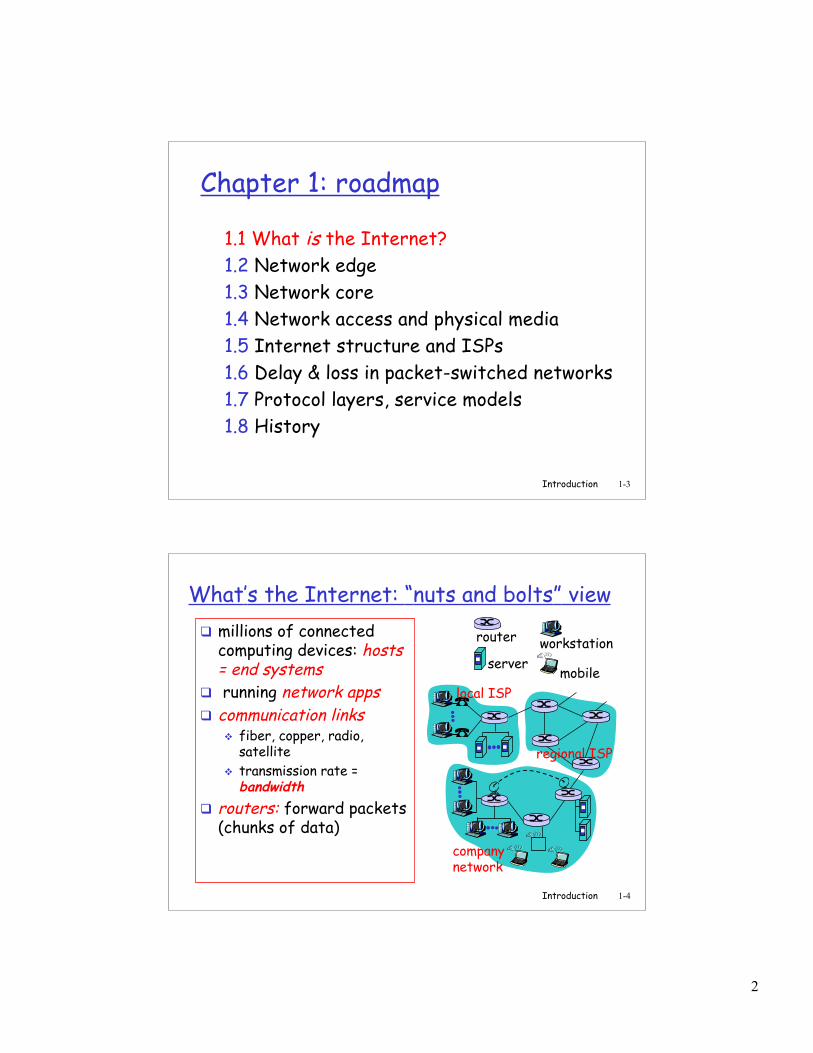
Chapter 1: roadmap
1.1 What is the Internet?1.2 Network edge1.3 Network core1.4 Network access and physical media1.5 Internet structure and ISPs1.6 Delay & loss in packet-switched networks1.7 Protocol layers, service models1.8 History
Introduction 1-4
What’s the Internet: “nuts and bolts” view millions of connected
computing devices: hosts= end systems
running network apps communication links
fiber, copper, radio,satellite
transmission rate =bandwidth
routers: forward packets(chunks of data)
local ISP
companynetwork
regional ISP
router workstationserver
mobile
3
Introduction 1-5
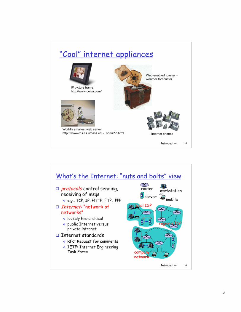
“Cool” internet appliances
World’s smallest web serverhttp://www-ccs.cs.umass.edu/~shri/iPic.html
IP picture framehttp://www.ceiva.com/
Web-enabled toaster +weather forecaster
Internet phones
Introduction 1-6
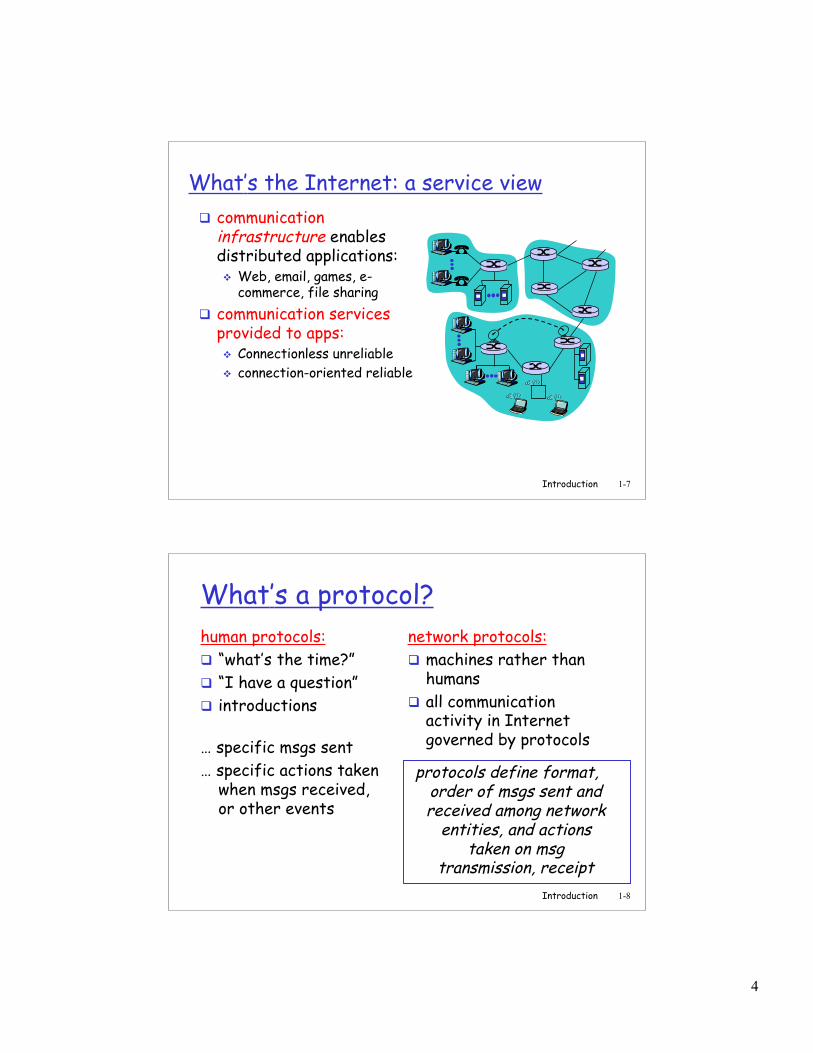
What’s the Internet: “nuts and bolts” view
protocols control sending,receiving of msgs e.g., TCP, IP, HTTP, FTP, PPP
Internet: “network ofnetworks” loosely hierarchical public Internet versus
private intranet Internet standards
RFC: Request for comments IETF: Internet Engineering
Task Force
local ISP
companynetwork
regional ISP
router workstationserver
mobile
4
Introduction 1-7
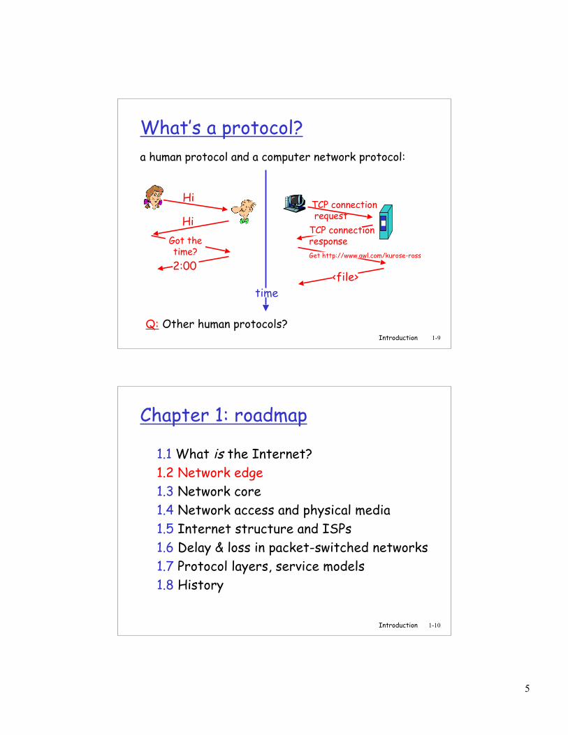
What’s the Internet: a service view communication
infrastructure enablesdistributed applications: Web, email, games, e-
commerce, file sharing communication services
provided to apps: Connectionless unreliable connection-oriented reliable
Introduction 1-8
What’s a protocol?human protocols: “what’s the time?” “I have a question” introductions
… specific msgs sent… specific actions taken
when msgs received,or other events
network protocols: machines rather than
humans all communication
activity in Internetgoverned by protocols
protocols define format,order of msgs sent andreceived among network
entities, and actionstaken on msg
transmission, receipt
5
Introduction 1-9
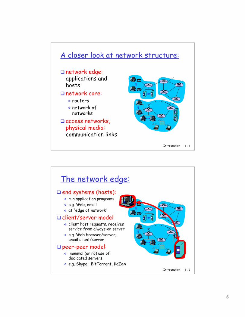
What’s a protocol?a human protocol and a computer network protocol:
Q: Other human protocols?
Hi
HiGot thetime?2:00
TCP connection requestTCP connectionresponseGet http://www.awl.com/kurose-ross
<file>time
Introduction 1-10
Chapter 1: roadmap
1.1 What is the Internet?1.2 Network edge1.3 Network core1.4 Network access and physical media1.5 Internet structure and ISPs1.6 Delay & loss in packet-switched networks1.7 Protocol layers, service models1.8 History
6
Introduction 1-11
A closer look at network structure:
network edge:applications andhosts
network core: routers network of
networks access networks,
physical media:communication links
Introduction 1-12
The network edge: end systems (hosts):
run application programs e.g. Web, email at “edge of network”
client/server model client host requests, receives
service from always-on server e.g. Web browser/server;
email client/server
peer-peer model: minimal (or no) use of
dedicated servers e.g. Skype, BitTorrent, KaZaA
7
Introduction 1-13
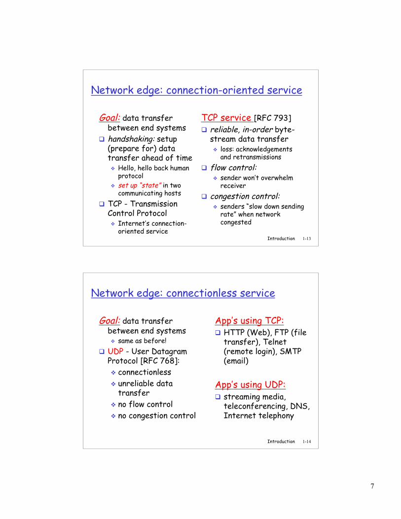
Network edge: connection-oriented service
Goal: data transferbetween end systems
handshaking: setup(prepare for) datatransfer ahead of time Hello, hello back human
protocol set up “state” in two
communicating hosts TCP - Transmission
Control Protocol Internet’s connection-
oriented service
TCP service [RFC 793] reliable, in-order byte-
stream data transfer loss: acknowledgements
and retransmissions flow control:
sender won’t overwhelmreceiver
congestion control: senders “slow down sending
rate” when networkcongested
Introduction 1-14
Network edge: connectionless service
Goal: data transferbetween end systems same as before!
UDP - User DatagramProtocol [RFC 768]: connectionless unreliable data
transfer no flow control no congestion control
App’s using TCP: HTTP (Web), FTP (file
transfer), Telnet(remote login), SMTP(email)
App’s using UDP: streaming media,
teleconferencing, DNS,Internet telephony
8
Introduction 1-15
Chapter 1: roadmap
1.1 What is the Internet?1.2 Network edge1.3 Network core1.4 Network access and physical media1.5 Internet structure and ISPs1.6 Delay & loss in packet-switched networks1.7 Protocol layers, service models1.8 History
Introduction 1-16
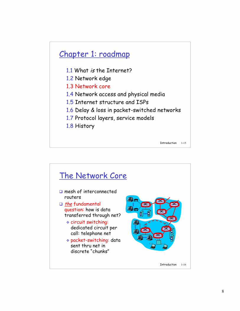
The Network Core
mesh of interconnectedrouters
the fundamentalquestion: how is datatransferred through net? circuit switching:
dedicated circuit percall: telephone net
packet-switching: datasent thru net indiscrete “chunks”
9
Introduction 1-17
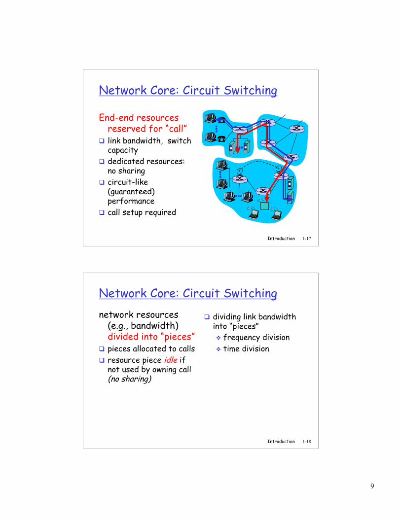
Network Core: Circuit Switching
End-end resourcesreserved for “call”
link bandwidth, switchcapacity
dedicated resources:no sharing
circuit-like(guaranteed)performance
call setup required
Introduction 1-18
Network Core: Circuit Switchingnetwork resources
(e.g., bandwidth)divided into “pieces”
pieces allocated to calls resource piece idle if
not used by owning call(no sharing)
dividing link bandwidthinto “pieces” frequency division time division
10
Introduction 1-19
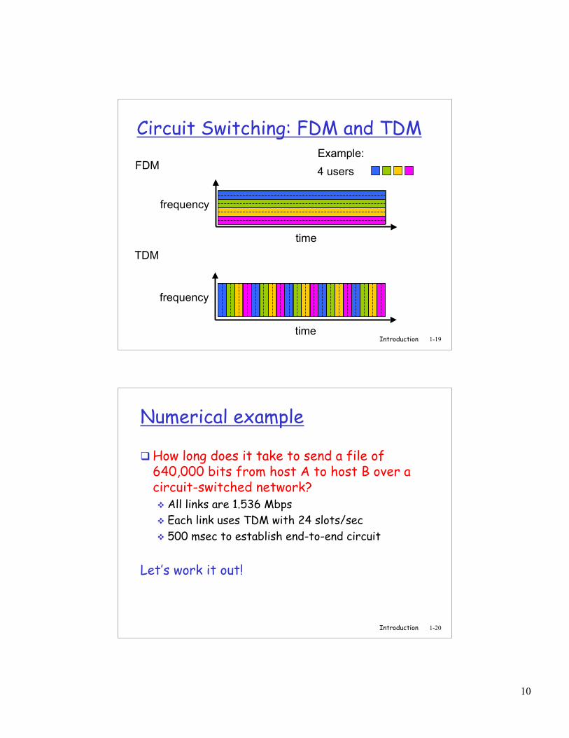
Circuit Switching: FDM and TDM
FDM
frequency
timeTDM
frequency
time
4 usersExample:
Introduction 1-20
Numerical example
How long does it take to send a file of640,000 bits from host A to host B over acircuit-switched network? All links are 1.536 Mbps Each link uses TDM with 24 slots/sec 500 msec to establish end-to-end circuit
Let’s work it out!
11
Introduction 1-21
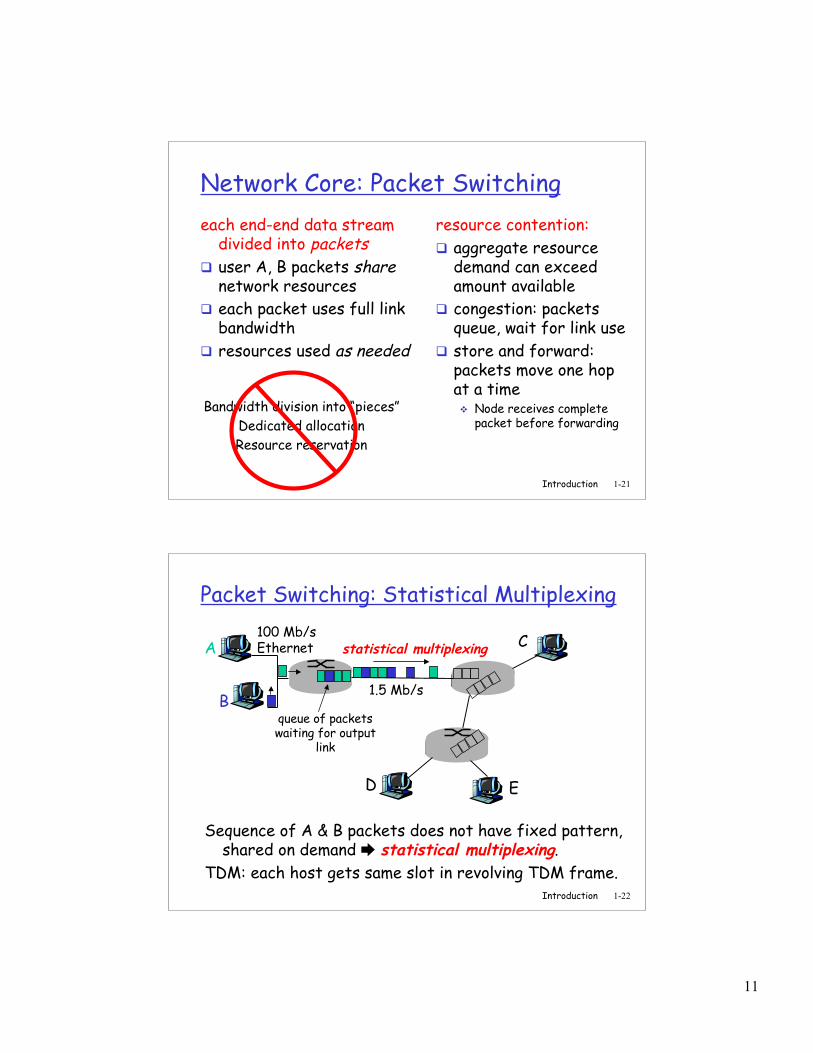
Network Core: Packet Switchingeach end-end data stream
divided into packets user A, B packets share
network resources each packet uses full link
bandwidth resources used as needed
resource contention: aggregate resource
demand can exceedamount available
congestion: packetsqueue, wait for link use
store and forward:packets move one hopat a time Node receives complete
packet before forwardingBandwidth division into “pieces”
Dedicated allocationResource reservation
Introduction 1-22
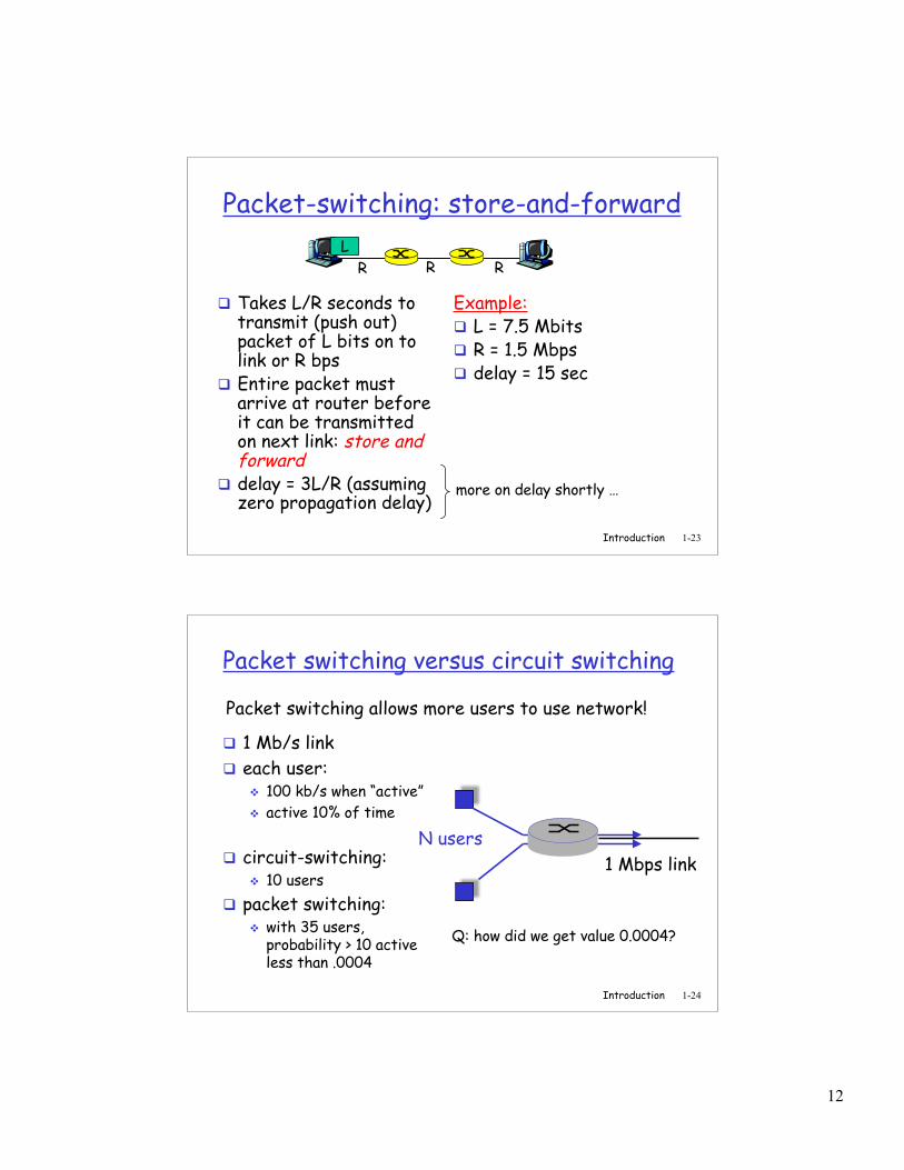
Packet Switching: Statistical Multiplexing
Sequence of A & B packets does not have fixed pattern,shared on demand statistical multiplexing.
TDM: each host gets same slot in revolving TDM frame.
A
B
C100 Mb/sEthernet
1.5 Mb/s
D E
statistical multiplexing
queue of packetswaiting for output
link
12
Introduction 1-23
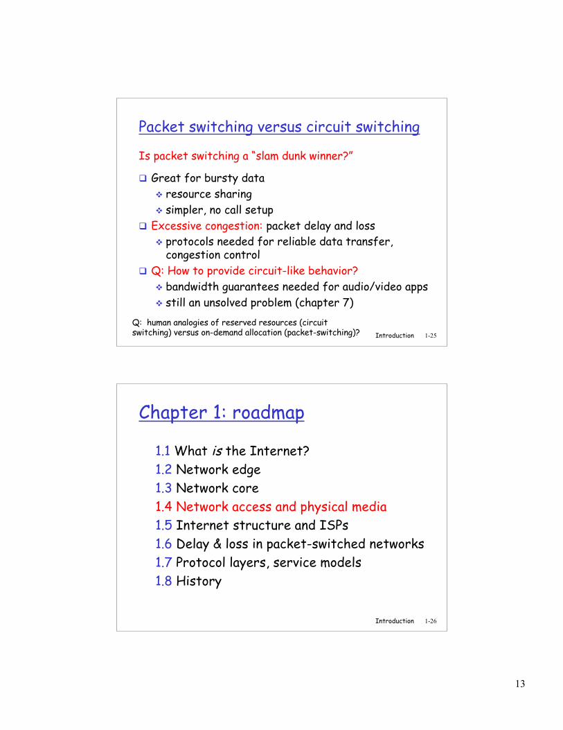
Packet-switching: store-and-forward
Takes L/R seconds totransmit (push out)packet of L bits on tolink or R bps
Entire packet mustarrive at router beforeit can be transmittedon next link: store andforward
delay = 3L/R (assumingzero propagation delay)
Example: L = 7.5 Mbits R = 1.5 Mbps delay = 15 sec
R R RL
more on delay shortly …
Introduction 1-24
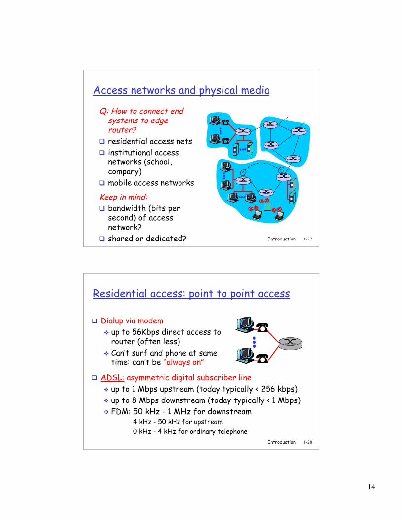
Packet switching versus circuit switching
1 Mb/s link each user:
100 kb/s when “active” active 10% of time
circuit-switching: 10 users
packet switching: with 35 users,
probability > 10 activeless than .0004
Packet switching allows more users to use network!
N users1 Mbps link
Q: how did we get value 0.0004?
13
Introduction 1-25
Packet switching versus circuit switching
Great for bursty data resource sharing simpler, no call setup
Excessive congestion: packet delay and loss protocols needed for reliable data transfer,
congestion control Q: How to provide circuit-like behavior?
bandwidth guarantees needed for audio/video apps still an unsolved problem (chapter 7)
Is packet switching a “slam dunk winner?”
Q: human analogies of reserved resources (circuitswitching) versus on-demand allocation (packet-switching)?
Introduction 1-26
Chapter 1: roadmap
1.1 What is the Internet?1.2 Network edge1.3 Network core1.4 Network access and physical media1.5 Internet structure and ISPs1.6 Delay & loss in packet-switched networks1.7 Protocol layers, service models1.8 History
14
Introduction 1-27
Access networks and physical media
Q: How to connect endsystems to edgerouter?
residential access nets institutional access
networks (school,company)
mobile access networks
Keep in mind: bandwidth (bits per
second) of accessnetwork?
shared or dedicated?
Introduction 1-28
Residential access: point to point access
Dialup via modem up to 56Kbps direct access to
router (often less) Can’t surf and phone at same
time: can’t be “always on”
ADSL: asymmetric digital subscriber line up to 1 Mbps upstream (today typically < 256 kbps) up to 8 Mbps downstream (today typically < 1 Mbps) FDM: 50 kHz - 1 MHz for downstream 4 kHz - 50 kHz for upstream 0 kHz - 4 kHz for ordinary telephone
15
Introduction 1-29
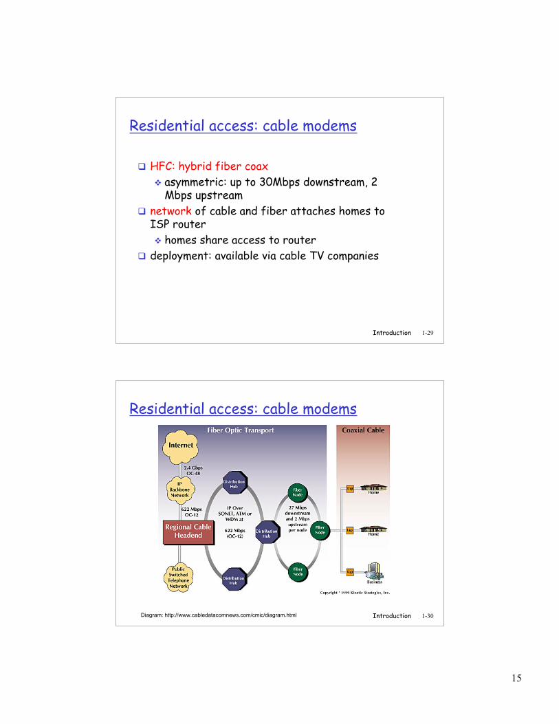
Residential access: cable modems
HFC: hybrid fiber coax asymmetric: up to 30Mbps downstream, 2
Mbps upstream network of cable and fiber attaches homes to
ISP router homes share access to router
deployment: available via cable TV companies
Introduction 1-30
Residential access: cable modems
Diagram: http://www.cabledatacomnews.com/cmic/diagram.html
16
Introduction 1-31
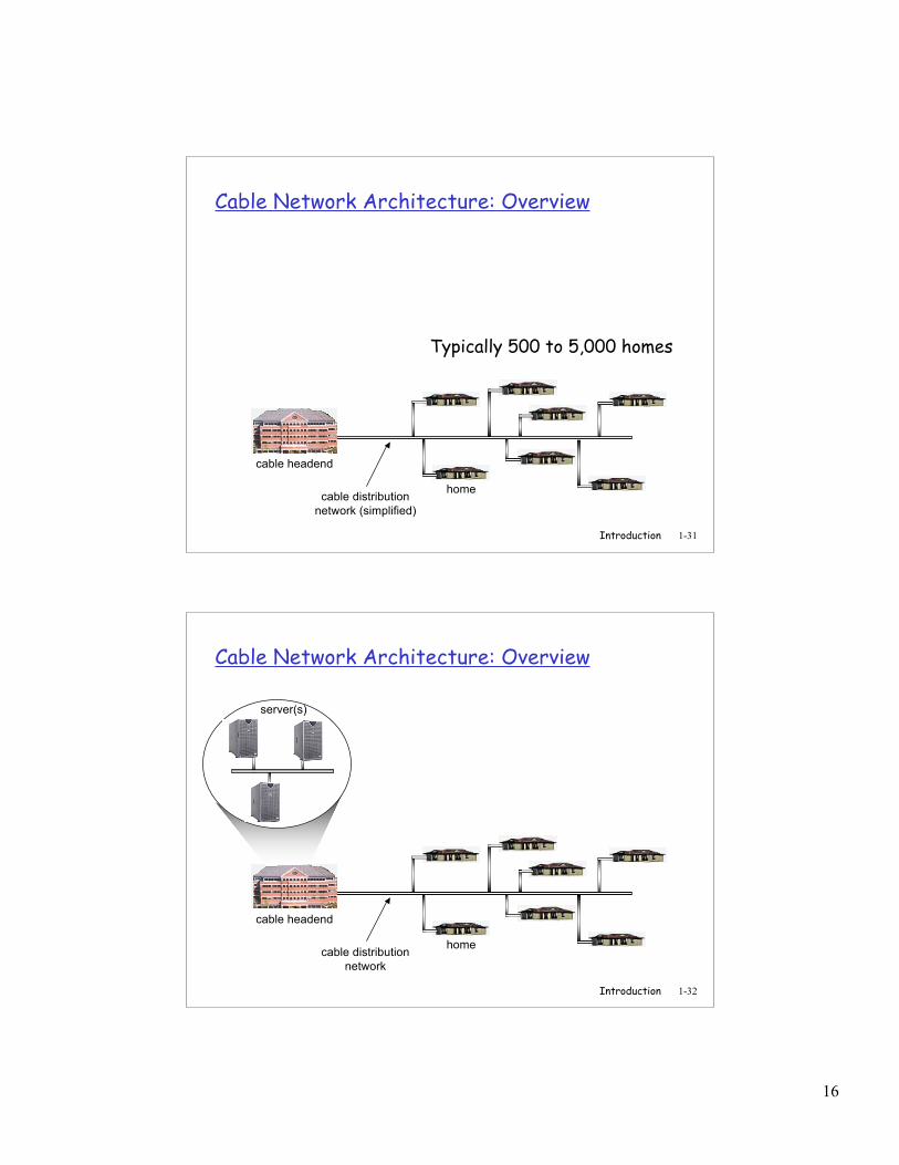
Cable Network Architecture: Overview
home
cable headend
cable distributionnetwork (simplified)
Typically 500 to 5,000 homes
Introduction 1-32
Cable Network Architecture: Overview
home
cable headend
cable distributionnetwork
server(s)
17
Introduction 1-33
Cable Network Architecture: Overview
home
cable headend
cable distributionnetwork (simplified)
Introduction 1-34
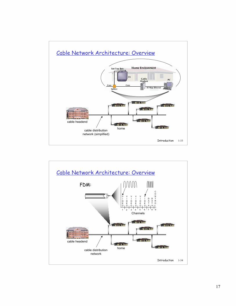
Cable Network Architecture: Overview
home
cable headend
cable distributionnetwork
Channels
VIDEO
VIDEO
VIDEO
VIDEO
VIDEO
VIDEO
DATA
DATA
CONTROL
1 2 3 4 5 6 7 8 9
FDM:
18
Introduction 1-35
Company access: local area networks
company/univ local areanetwork (LAN) connectsend system to edge router
Ethernet: shared or dedicated link
connects end systemand router
10 Mbs, 100Mbps,Gigabit Ethernet
LANs: chapter 5
Introduction 1-36
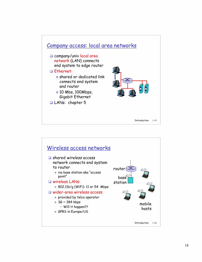
Wireless access networks
shared wireless accessnetwork connects end systemto router via base station aka “access
point” wireless LANs:
802.11b/g (WiFi): 11 or 54 Mbps wider-area wireless access
provided by telco operator 3G ~ 384 kbps
• Will it happen?? GPRS in Europe/US
basestation
mobilehosts
router
19
Introduction 1-37
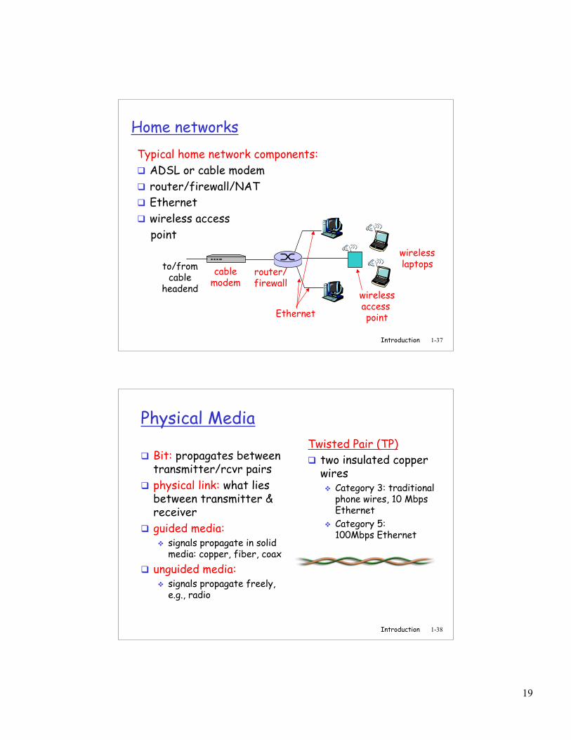
Home networksTypical home network components: ADSL or cable modem router/firewall/NAT Ethernet wireless access point
wirelessaccess point
wirelesslaptops
router/firewall
cablemodem
to/fromcable
headend
Ethernet
Introduction 1-38
Physical Media
Bit: propagates betweentransmitter/rcvr pairs
physical link: what liesbetween transmitter &receiver
guided media: signals propagate in solid
media: copper, fiber, coax unguided media:
signals propagate freely,e.g., radio
Twisted Pair (TP) two insulated copper
wires Category 3: traditional
phone wires, 10 MbpsEthernet
Category 5:100Mbps Ethernet

20
Introduction 1-39
Physical Media: coax, fiber
Coaxial cable: two concentric copper
conductors bidirectional baseband:
single channel on cable legacy Ethernet
broadband: multiple channels on
cable HFC
Fiber optic cable: glass fiber carrying light
pulses, each pulse a bit high-speed operation:
high-speed point-to-pointtransmission (e.g., 10’s-100’s Gps)
low error rate: repeatersspaced far apart ; immuneto electromagnetic noise
Introduction 1-40
Physical media: radio
signal carried inelectromagneticspectrum
no physical “wire” bidirectional propagation
environment effects: reflection obstruction by objects interference
Radio link types: terrestrial microwave
e.g. up to 45 Mbps channels LAN (e.g., Wifi)
11Mbps, 54 Mbps wide-area (e.g., cellular)
e.g. 3G: hundreds of kbps satellite
Kbps to 45Mbps channel (ormultiple smaller channels)
270 msec end-end delay geosynchronous versus low
altitude
21
Introduction 1-41
Chapter 1: roadmap
1.1 What is the Internet?1.2 Network edge1.3 Network core1.4 Network access and physical media1.5 Internet structure and ISPs1.6 Delay & loss in packet-switched networks1.7 Protocol layers, service models1.8 History
Introduction 1-42
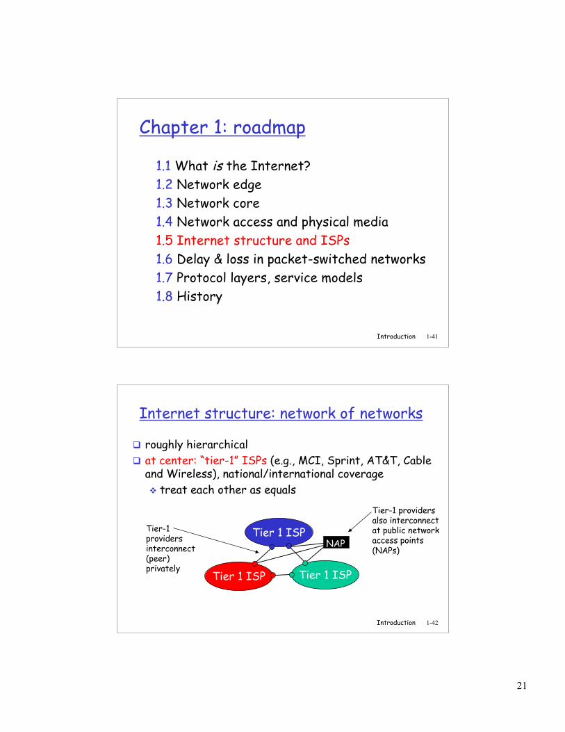
Internet structure: network of networks
roughly hierarchical at center: “tier-1” ISPs (e.g., MCI, Sprint, AT&T, Cable
and Wireless), national/international coverage treat each other as equals
Tier 1 ISP
Tier 1 ISP
Tier 1 ISP
Tier-1providersinterconnect(peer)privately
NAP
Tier-1 providersalso interconnectat public networkaccess points(NAPs)
22
Introduction 1-43
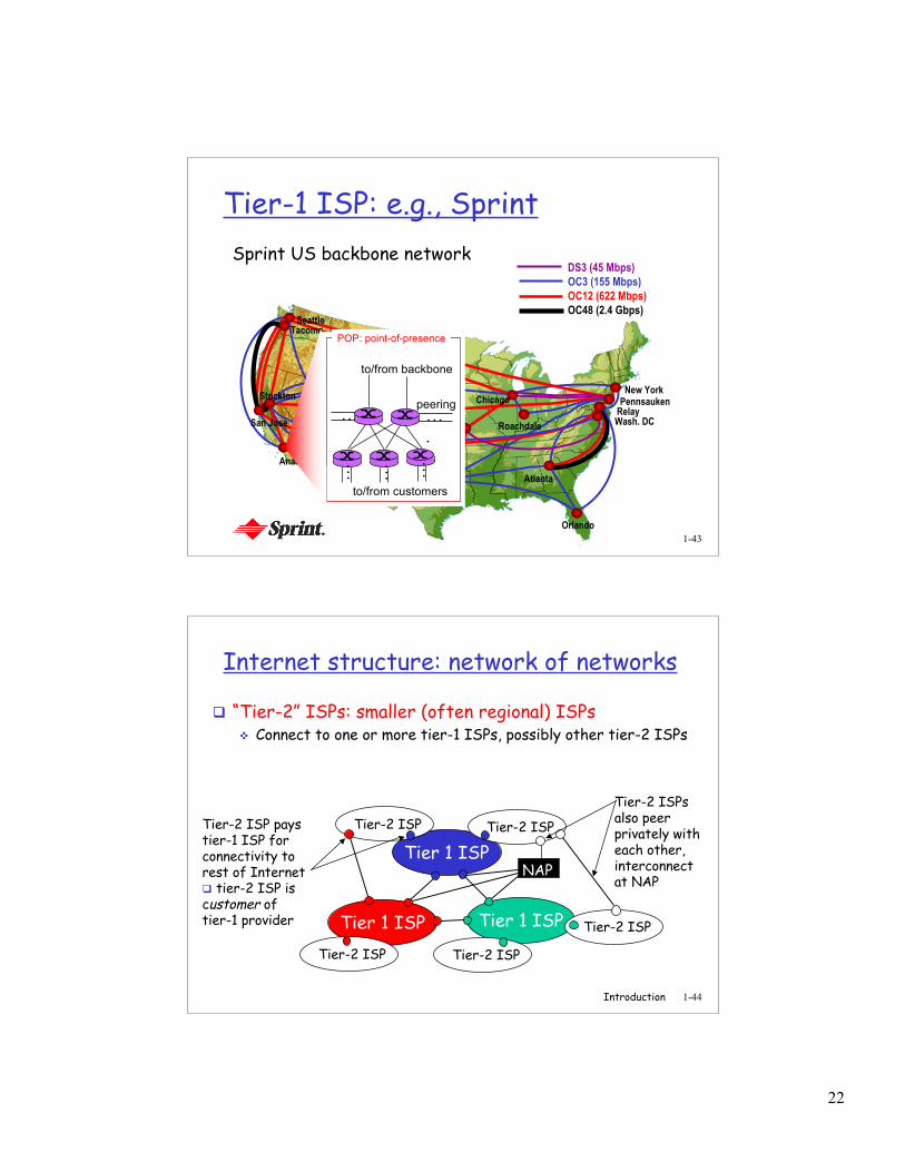
Tier-1 ISP: e.g., SprintSprint US backbone network
Seattle
Atlanta
Chicago
Roachdale
Stockton
San Jose
Anaheim
Fort Worth
Orlando
Kansas City
CheyenneNew York
PennsaukenRelayWash. DC
Tacoma
DS3 (45 Mbps)OC3 (155 Mbps)OC12 (622 Mbps)OC48 (2.4 Gbps)
…
to/from customers
peering
to/from backbone
….
………POP: point-of-presence
Introduction 1-44
Internet structure: network of networks
“Tier-2” ISPs: smaller (often regional) ISPs Connect to one or more tier-1 ISPs, possibly other tier-2 ISPs
Tier 1 ISP
Tier 1 ISP
Tier 1 ISP
NAP
Tier-2 ISPTier-2 ISP
Tier-2 ISP Tier-2 ISP
Tier-2 ISP
Tier-2 ISP paystier-1 ISP forconnectivity torest of Internet tier-2 ISP iscustomer oftier-1 provider
Tier-2 ISPsalso peerprivately witheach other,interconnectat NAP
23
Introduction 1-45
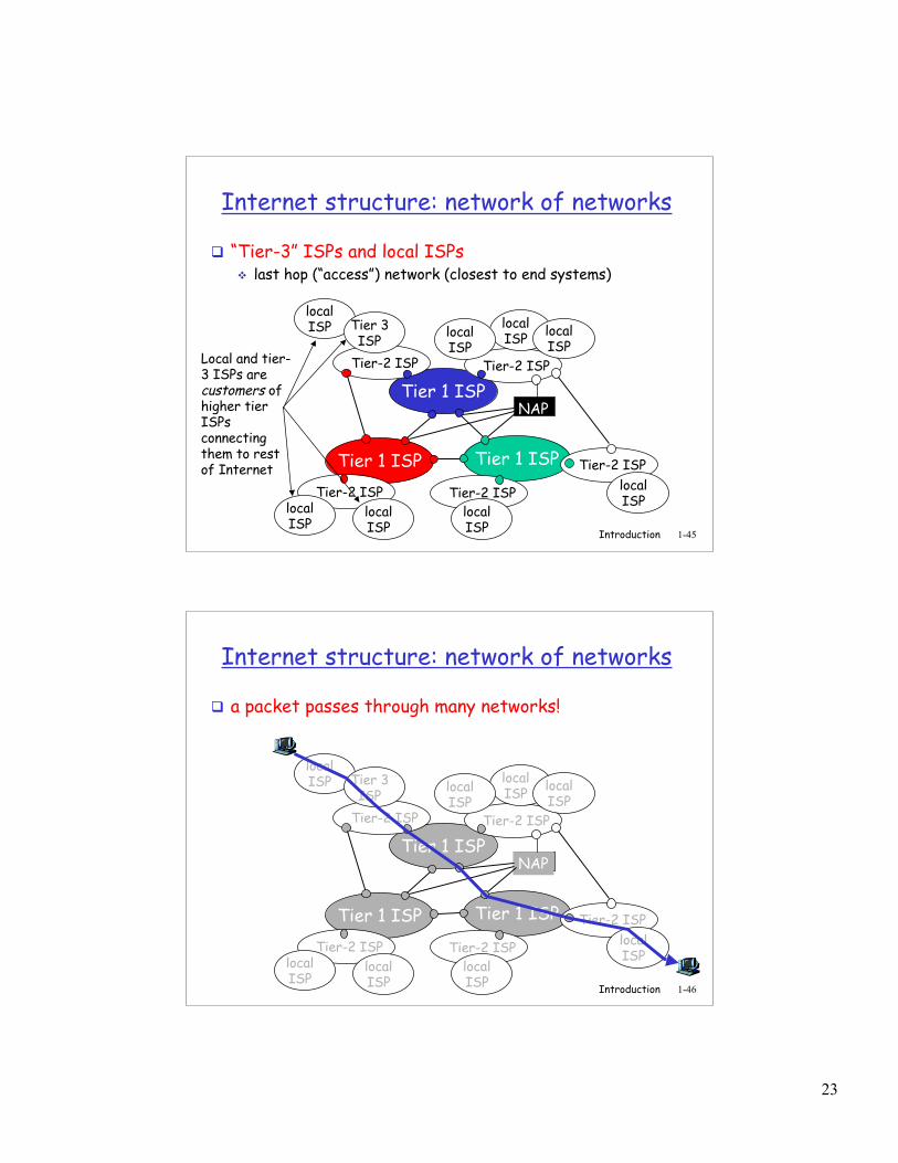
Internet structure: network of networks
“Tier-3” ISPs and local ISPs last hop (“access”) network (closest to end systems)
Tier 1 ISP
Tier 1 ISP
Tier 1 ISP
NAP
Tier-2 ISPTier-2 ISP
Tier-2 ISP Tier-2 ISP
Tier-2 ISP
localISPlocal
ISPlocalISP
localISP
localISP Tier 3
ISP
localISP
localISP
localISP
Local and tier-3 ISPs arecustomers ofhigher tierISPsconnectingthem to restof Internet
Introduction 1-46
Internet structure: network of networks
a packet passes through many networks!
Tier 1 ISP
Tier 1 ISP
Tier 1 ISP
NAP
Tier-2 ISPTier-2 ISP
Tier-2 ISP Tier-2 ISP
Tier-2 ISP
localISPlocal
ISPlocalISP
localISP
localISP Tier 3
ISP
localISP
localISP
localISP
24
Introduction 1-47
Chapter 1: roadmap
1.1 What is the Internet?1.2 Network edge1.3 Network core1.4 Network access and physical media1.5 Internet structure and ISPs1.6 Delay & loss in packet-switched networks1.7 Protocol layers, service models1.8 History
Introduction 1-48
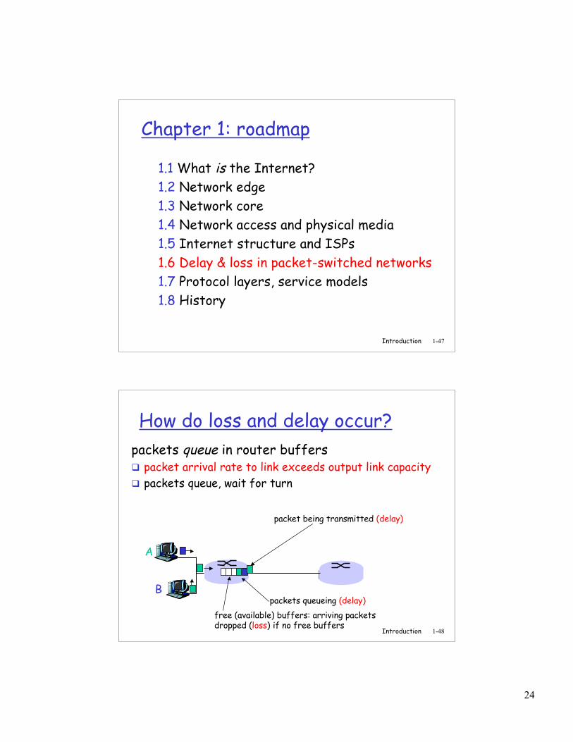
How do loss and delay occur?packets queue in router buffers packet arrival rate to link exceeds output link capacity packets queue, wait for turn
A
B
packet being transmitted (delay)
packets queueing (delay)free (available) buffers: arriving packets dropped (loss) if no free buffers
25
Introduction 1-49
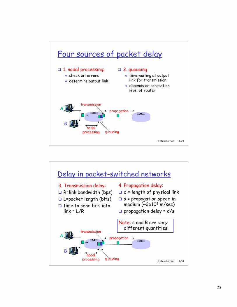
Four sources of packet delay
1. nodal processing: check bit errors determine output link
A
B
propagation
transmission
nodalprocessing queueing
2. queueing time waiting at output
link for transmission depends on congestion
level of router
Introduction 1-50
Delay in packet-switched networks3. Transmission delay: R=link bandwidth (bps) L=packet length (bits) time to send bits into
link = L/R
4. Propagation delay: d = length of physical link s = propagation speed in
medium (~2x10⁸ m/sec) propagation delay = d/s
A
B
propagation
transmission
nodalprocessing queueing
Note: s and R are verydifferent quantities!
26
Introduction 1-51
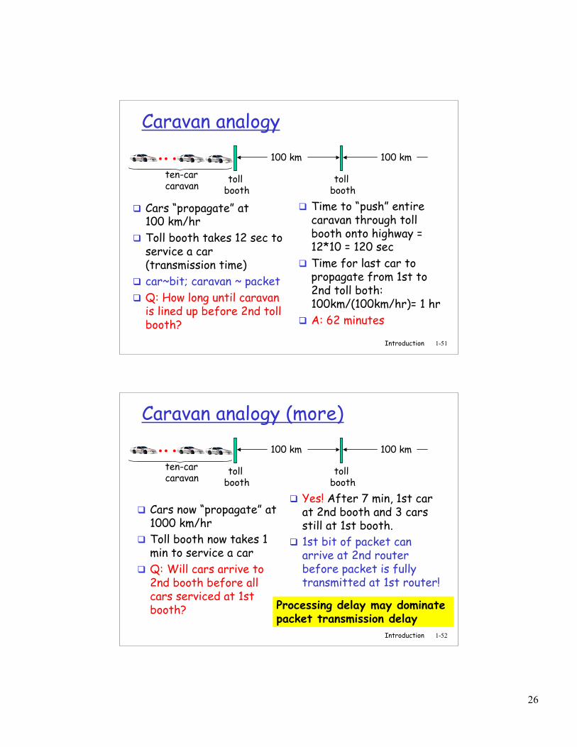
Caravan analogy
Cars “propagate” at100 km/hr
Toll booth takes 12 sec toservice a car(transmission time)
car~bit; caravan ~ packet Q: How long until caravan
is lined up before 2nd tollbooth?
Time to “push” entirecaravan through tollbooth onto highway =12*10 = 120 sec
Time for last car topropagate from 1st to2nd toll both:100km/(100km/hr)= 1 hr
A: 62 minutes
toll booth
toll booth
ten-car caravan
100 km 100 km
Introduction 1-52
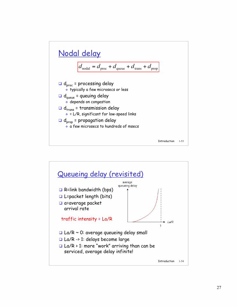
Caravan analogy (more)
Cars now “propagate” at1000 km/hr
Toll booth now takes 1min to service a car
Q: Will cars arrive to2nd booth before allcars serviced at 1stbooth?
Yes! After 7 min, 1st carat 2nd booth and 3 carsstill at 1st booth.
1st bit of packet canarrive at 2nd routerbefore packet is fullytransmitted at 1st router!
toll booth
toll booth
ten-car caravan
100 km 100 km
Processing delay may dominate packet transmission delay
27
Introduction 1-53
Nodal delay
dproc = processing delay typically a few microsecs or less
dqueue = queuing delay depends on congestion
dtrans = transmission delay = L/R, significant for low-speed links
dprop = propagation delay a few microsecs to hundreds of msecs
proptransqueueprocnodal ddddd +++=
Introduction 1-54
Queueing delay (revisited)
R=link bandwidth (bps) L=packet length (bits) a=average packet
arrival rate
traffic intensity = La/R
La/R ~ 0: average queueing delay small La/R -> 1: delays become large La/R > 1: more “work” arriving than can be
serviced, average delay infinite!
28
Introduction 1-55
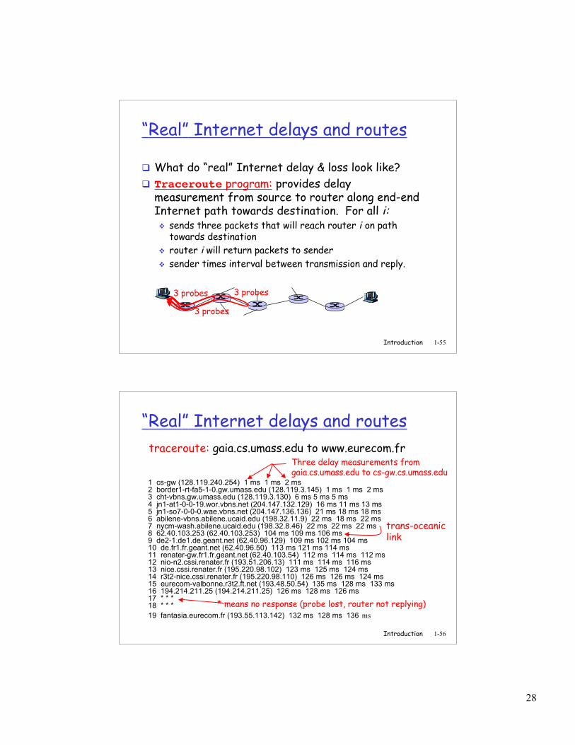
“Real” Internet delays and routes
What do “real” Internet delay & loss look like? Traceroute program: provides delay
measurement from source to router along end-endInternet path towards destination. For all i: sends three packets that will reach router i on path
towards destination router i will return packets to sender sender times interval between transmission and reply.
3 probes
3 probes
3 probes
Introduction 1-56
“Real” Internet delays and routes
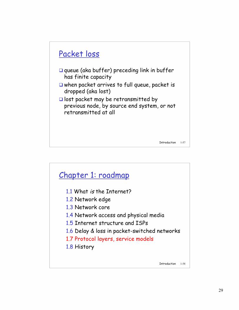
1 cs-gw (128.119.240.254) 1 ms 1 ms 2 ms2 border1-rt-fa5-1-0.gw.umass.edu (128.119.3.145) 1 ms 1 ms 2 ms3 cht-vbns.gw.umass.edu (128.119.3.130) 6 ms 5 ms 5 ms4 jn1-at1-0-0-19.wor.vbns.net (204.147.132.129) 16 ms 11 ms 13 ms5 jn1-so7-0-0-0.wae.vbns.net (204.147.136.136) 21 ms 18 ms 18 ms6 abilene-vbns.abilene.ucaid.edu (198.32.11.9) 22 ms 18 ms 22 ms7 nycm-wash.abilene.ucaid.edu (198.32.8.46) 22 ms 22 ms 22 ms8 62.40.103.253 (62.40.103.253) 104 ms 109 ms 106 ms9 de2-1.de1.de.geant.net (62.40.96.129) 109 ms 102 ms 104 ms10 de.fr1.fr.geant.net (62.40.96.50) 113 ms 121 ms 114 ms11 renater-gw.fr1.fr.geant.net (62.40.103.54) 112 ms 114 ms 112 ms12 nio-n2.cssi.renater.fr (193.51.206.13) 111 ms 114 ms 116 ms13 nice.cssi.renater.fr (195.220.98.102) 123 ms 125 ms 124 ms14 r3t2-nice.cssi.renater.fr (195.220.98.110) 126 ms 126 ms 124 ms15 eurecom-valbonne.r3t2.ft.net (193.48.50.54) 135 ms 128 ms 133 ms16 194.214.211.25 (194.214.211.25) 126 ms 128 ms 126 ms17 * * *18 * * *19 fantasia.eurecom.fr (193.55.113.142) 132 ms 128 ms 136 ms
traceroute: gaia.cs.umass.edu to www.eurecom.frThree delay measurements fromgaia.cs.umass.edu to cs-gw.cs.umass.edu
* means no response (probe lost, router not replying)
trans-oceaniclink
29
Introduction 1-57
Packet loss
queue (aka buffer) preceding link in bufferhas finite capacity
when packet arrives to full queue, packet isdropped (aka lost)
lost packet may be retransmitted byprevious node, by source end system, or notretransmitted at all
Introduction 1-58
Chapter 1: roadmap
1.1 What is the Internet?1.2 Network edge1.3 Network core1.4 Network access and physical media1.5 Internet structure and ISPs1.6 Delay & loss in packet-switched networks1.7 Protocol layers, service models1.8 History
30
Introduction 1-59
Protocol “Layers”Networks are complex! many “pieces”:
hosts routers links of various
media applications protocols hardware,
software
Question:Is there any hope oforganizing structure of
network?
Or at least our discussionof networks?
Introduction 1-60
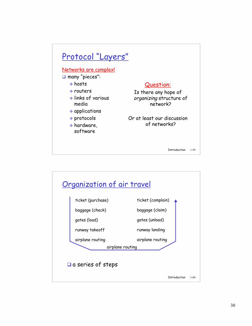
Organization of air travel
a series of steps
ticket (purchase)
baggage (check)
gates (load)
runway takeoff
airplane routing
ticket (complain)
baggage (claim)
gates (unload)
runway landing
airplane routing
airplane routing
31
Introduction 1-61
ticket (purchase)
baggage (check)
gates (load)
runway (takeoff)
airplane routing
departureairport
arrivalairport
intermediate air-trafficcontrol centers
airplane routing airplane routing
ticket (complain)
baggage (claim
gates (unload)
runway (land)
airplane routing
ticket
baggage
gate
takeoff/landing
airplane routing
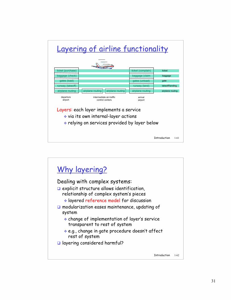
Layering of airline functionality
Layers: each layer implements a service via its own internal-layer actions relying on services provided by layer below
Introduction 1-62
Why layering?Dealing with complex systems: explicit structure allows identification,
relationship of complex system’s pieces layered reference model for discussion
modularization eases maintenance, updating ofsystem change of implementation of layer’s service
transparent to rest of system e.g., change in gate procedure doesn’t affect
rest of system layering considered harmful?
32
Introduction 1-63
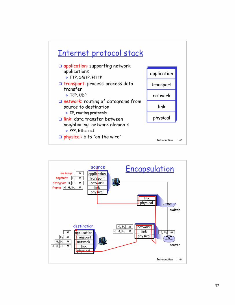
Internet protocol stack application: supporting network
applications FTP, SMTP, HTTP
transport: process-process datatransfer TCP, UDP
network: routing of datagrams fromsource to destination IP, routing protocols
link: data transfer betweenneighboring network elements PPP, Ethernet
physical: bits “on the wire”
application
transport
network
link
physical
Introduction 1-64
sourceapplicationtransportnetwork
linkphysical
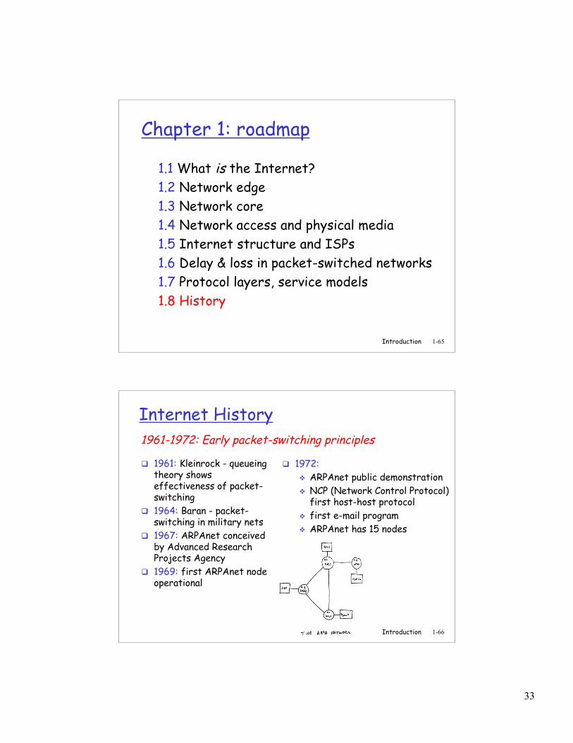
HtHn M
segment Ht
datagram
destinationapplicationtransportnetwork
linkphysical
HtHnHl MHtHn M
Ht M
M
networklink
physical
linkphysical
HtHnHl M
HtHn M
HtHn M
HtHnHl M
router
switch
Encapsulationmessage M
Ht M
Hnframe
33
Introduction 1-65
Chapter 1: roadmap
1.1 What is the Internet?1.2 Network edge1.3 Network core1.4 Network access and physical media1.5 Internet structure and ISPs1.6 Delay & loss in packet-switched networks1.7 Protocol layers, service models1.8 History
Introduction 1-66
Internet History
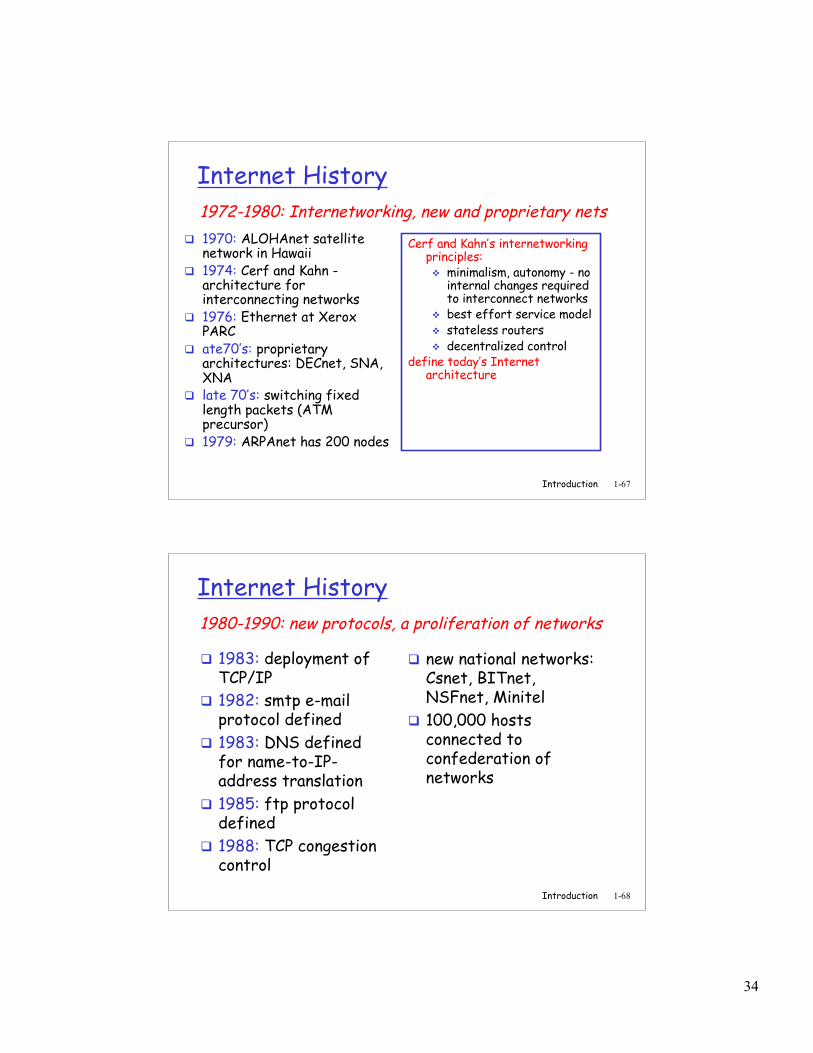
1961: Kleinrock - queueingtheory showseffectiveness of packet-switching
1964: Baran - packet-switching in military nets
1967: ARPAnet conceivedby Advanced ResearchProjects Agency
1969: first ARPAnet nodeoperational
1972: ARPAnet public demonstration NCP (Network Control Protocol)
first host-host protocol first e-mail program ARPAnet has 15 nodes
1961-1972: Early packet-switching principles
34
Introduction 1-67
Internet History
1970: ALOHAnet satellitenetwork in Hawaii
1974: Cerf and Kahn -architecture forinterconnecting networks
1976: Ethernet at XeroxPARC
ate70’s: proprietaryarchitectures: DECnet, SNA,XNA
late 70’s: switching fixedlength packets (ATMprecursor)
1979: ARPAnet has 200 nodes
Cerf and Kahn’s internetworkingprinciples: minimalism, autonomy - no
internal changes requiredto interconnect networks
best effort service model stateless routers decentralized control
define today’s Internetarchitecture
1972-1980: Internetworking, new and proprietary nets
Introduction 1-68
Internet History
1983: deployment ofTCP/IP
1982: smtp e-mailprotocol defined
1983: DNS definedfor name-to-IP-address translation
1985: ftp protocoldefined
1988: TCP congestioncontrol
new national networks:Csnet, BITnet,NSFnet, Minitel
100,000 hostsconnected toconfederation ofnetworks
1980-1990: new protocols, a proliferation of networks
35
Introduction 1-69
Internet History
Early 1990’s: ARPAnetdecommissioned
1991: NSF lifts restrictions oncommercial use of NSFnet(decommissioned, 1995)
early 1990s: Web hypertext [Bush 1945, Nelson
1960’s] HTML, HTTP: Berners-Lee 1994: Mosaic, later Netscape late 1990’s:
commercialization of the Web
Late 1990’s – 2000’s: more killer apps: instant
messaging, P2P file sharing network security to
forefront est. 50 million host, 100
million+ users backbone links running at
Gbps
1990, 2000’s: commercialization, the Web, new apps
Introduction 1-70
Introduction: Summary
Covered a “ton” of material! Internet overview what’s a protocol? network edge, core, access
network packet-switching versus
circuit-switching Internet/ISP structure performance: loss, delay layering and service
models history
You now have: context, overview,
“feel” of networking more depth, detail to
follow!