
Chapter 6: First Order Circuits -...
37
Chapter 6: First Order Circuits 1. The source-free RC circuits 2. The source-free RL circuits 3. Singularity Functions 4. Step Response of an RC Circuit 5. Step Response of an RL Circuit Copyright © The McGraw-Hill Companies, Inc. Permission required for reproduction or display.
Transcript of Chapter 6: First Order Circuits -...
Chapter 6: First Order Circuits
1. The source-free RC circuits
2. The source-free RL circuits
3. Singularity Functions
4. Step Response of an RC Circuit
5. Step Response of an RL Circuit
Copyright © The McGraw-Hill Companies, Inc. Permission required for reproduction or display.

Learning Outcomes...
At the end of this topic, students should be able to: • Describe the RC and RL circuit and its connection with
the time constant• Formulate and solve the differential equation to
describe the circuit’s behaviour• Explain the natural and forced responses of the first
order RC and RL circuits• Determine the natural and forced responses of the first
order RC and RL circuits

Source-free RC Circuit
• Consider a circuit below:
Apply Kirchhoff’s laws to purely resistive circuit results in algebraic
equations.
Apply the laws to RC and RL circuits produces differential equations.
• A first-order circuit is characterized by a first-order differential equation.
Ohms law Capacitor law
0 =+dt
dvC
R
v0 =+ CR ii
By KCL

Source-free RC Circuit
Solving this homogeneous equation:
Therefore,
DCR
tv
dtRC
dvv
RC
v
dt
dvdt
dvC
R
v
+−=
−=
−=
=+
∫∫
ln
11
0
D
t
DCR
t
eeeev τ==−
CR=τTime constant
Initial condition, v(0)

Source-Free RC Circuit (cont.)
• The natural response of a circuit refers to the behavior (in terms of voltages and currents) of the circuit itself, with no external sources of excitation.
• The time constant τ of a circuit is the time required for the response to decay by a factor of 1/e or 36.8% of its initial value.
• v decays faster for small τ and slower for large τ.
CR=τTime constantDecays more slowly
Decays faster

Source-Free RC Circuit (cont.)
The key to working with a source-free RC circuit is finding:
1. The initial voltage v(0) = V0 across the capacitor.
2. The time constant τ = RC.
τ−=
/
0)(
teVtv CR=τwhere

Example 1
Refer to the circuit below, determine vC, vx, and io for t ≥ 0.
Assume that vC(0) = 30 V.
• Please refer to lecture or textbook for more detail elaboration.
Answer: vC = 30e–0.25t V ; vx = 10e
–0.25t ; io = –2.5e–0.25t A

Example 2
The switch in circuit below is opened at t = 0, find v(t) for t ≥ 0.
• Please refer to lecture or textbook for more detail elaboration.
Answer: V(t) = 8e–2t V

Example 3
For the circuit shown below, find v when v(0) = 10 V.
• Please refer to lecture or textbook for more detail elaboration.
Answer: v(t) = 10e–5000t V

Source-Free RL Circuit
• A first-order RL circuit consists of a inductor L (or its equivalent) and a resistor (or its equivalent)
0 =+ RL vvBy KVL
0 =+ iRdt
diL
Inductors law Ohms law
dtL
R
i
di−=
LtReIti
/
0 )(−
=
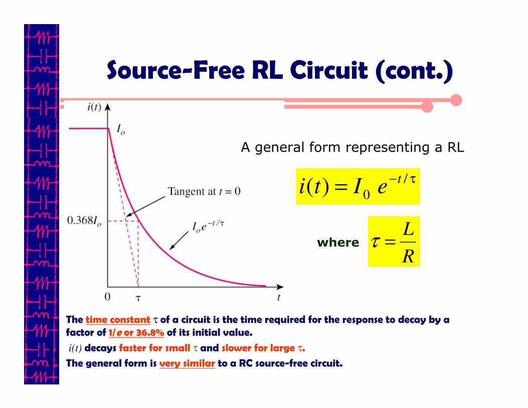
Source-Free RL Circuit (cont.)
• The time constant τ of a circuit is the time required for the response to decay by a factor of 1/e or 36.8% of its initial value.
• i(t) decays faster for small τ and slower for large τ.
• The general form is very similar to a RC source-free circuit.
τ−=
/
0)(t
eIti
R
L=τ
A general form representing a RL
where

Source-Free RL Circuit (cont.)
τ−=
/
0)(t
eItiR
L=τ
A RL source-free circuit
where τ/
0)(t
eVtv−
= RC=τ
A RC source-free circuit
where
Comparison between a RL and RC circuit

Source-Free RL Circuit (cont.)
The key to working with a source-free RL circuit is finding:
1. The initial voltage i(0) = I0 through the inductor.
2. The time constant τ = L/R.
τ/
0)(
teIti
−=
R
L=τwhere

Example 1
Determine the current i(t) for t ≥ 0s for the circuit shown below. Assume that the switch was closed a long time.
Answer: i= 2/7 e-100t

Example 2
Determine the inductor current, iL(t) for t ≥0s for the circuit shown below. Assume that switch was at position 1 for a long time.
Answer: iL= 10 e-76.9t mA

Example 3
Find i and vx in the circuit. Assume that i(0) = 5 A.
• Please refer to lecture or textbook for more detail elaboration.
Answer: i(t) = 5e–53t A

Example 4
For the circuit, find i(t) for t > 0.
• Please refer to lecture or textbook for more detail elaboration.
Answer: i(t) = 2e–2t A

Unit-Step Function
• The unit step function u(t) is 0 for negative values of t
and 1 for positive values of t.
>
<=
0,1
0,0)(
t
ttu
>
<=−
o
o
ott
ttttu
,1
,0)(
−>
−<=+
o
o
ott
ttttu
,1
,0)(

Unit-Step Function
1. voltage source.
2. for current source:
Represent an abrupt change for:

• Initial condition: v(0-) = v(0+) = V0
• Applying KCL,
or
• Where u(t) is the unit-step function
Step-Response of a RC Circuit
• The step response of a circuit is its behavior when the excitation is the step function, which may be a voltage or a current source.
0)(
=−
+R
tuVv
dt
dvC s
)(tuRC
Vv
dt
dv s−−=

Step-Response of a RC Circuit
Solving this equation:
Therefore,
( )
( )
CR
t
VV
Vv
dtRC
dvVv
tuRCdt
dv
Vv
tuRC
Vv
dt
dv
S
S
tv
VS
S
S
−=−
−
−=−
−=−
−−=
∫∫
0
0
ln
11
11
0
( ) CR
t
SS eVVVv−
−+= 0
CR=τTime constant
Initial condition, v(0)
CR
t
S
S eVV
Vv −
=−
−⇒
0

Step-Response of a RC Circuit (cont.)
• Integrating both sides and considering the initial conditions, the solution of the equation is:
>−+
<=
−0)(
0)(
/
0
0
teVVV
tVtv
t
ss
τ
Final value at t -> ∞
Initial value at t = 0
Source-free Response
Complete Response = Natural response + Forced Response(stored energy) (independent source)
= V0e–t/τ + Vs(1–e–t/τ)

Step-Response of a RC Circuit (cont.)
Three steps to find out the step response of an RC circuit:
1. The initial capacitor voltage v(0).
2. The final capacitor voltage v(∞) — DC voltage across C.
3. The time constant τ.
τ/ )]( )0( [ )( )(
tevvvtv
−∞−++∞=
Note: The above method is a short-cut method. You may also determine the solution by setting up the circuit formula directly using KCL, KVL , ohms law, capacitor and inductor VI laws.

Example 1
Find the capacitor voltage and current for t ≥ 0 s for the circuit shown below. At what time does the voltage v pass through zero?
Assume that the switch was in position 1 for a long time prior to t = 0-s.
Answer: v = 120 – 180 e-tV; t = 0.41 s

Solution
Determine the initial voltage, v at t ≤ 0s, i.e. v(0).
The switch has been in position 1 for a long time so the capacitor looks like an open circuit.
( )
V
v
60
8026
6
−=
−+
=
Therefore, the voltage across 6 Ω resistor is (use voltage divider rule)
-ve sign is due to the reference for v is opposite to that of 80 V voltage source.
Solution (cont.)
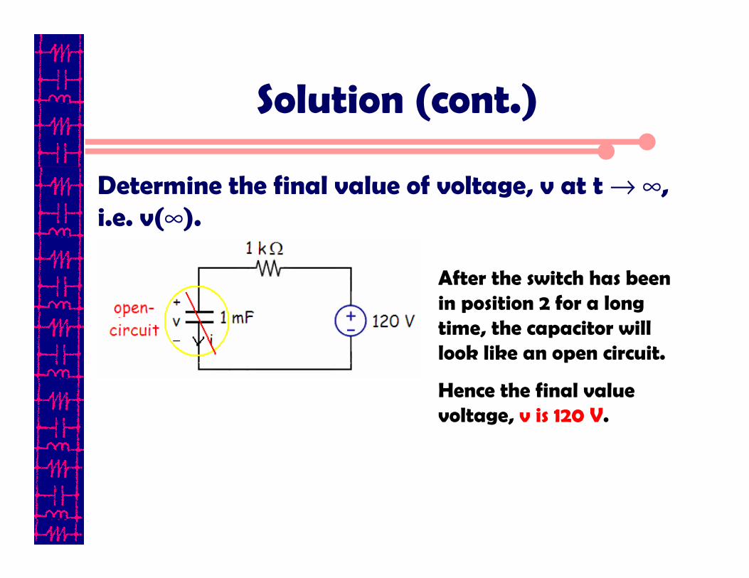
Determine the final value of voltage, v at t → ∞, i.e. v(∞).
After the switch has been in position 2 for a long time, the capacitor will look like an open circuit.
Hence the final value voltage, v is 120 V.

Solution (cont.)
Determine the time constant, τ at t → 0s.
s
RC
1
10110133
=
×××=
=−
τ
Time constant,

Solution (cont.)
We know that the total response, v(t) is given by
Therefore
To find t when v = 0 V,
( ) ( ) ( )[ ] τ
t
evvvv−
∞−+∞= 0
[ ]Ve
evt
t
−
−
−=
−−+=
180120
12060120 1
( ) st
e
ev
t
t
405.032ln3
2
180
120
0180120
=−=
==
=−=
−
−

Solution (cont.)
To find, i(t), we know that
Therefore
dt
dvCi =
( )
( )( )Ae
e
edt
di
t
t
t
−
−−
−−
=
−−××=
−×=
18.0
1180101
180120101
3
3

Find v(t) for t > 0 s in the circuit shown below. Assume the switch has been opened for a long time and is closed at t = 0 s.
Calculate v(t) at t = 0.5.
Example 2
• Please refer to lecture or textbook for more detail elaboration.
Answer: and v(0.5) = 0.5182V515)(2
−=− t
etv

Step-response of a RL Circuit
• The step response of a circuit is its behavior when the excitation is the step function, which may be a voltage or a current source.
• Initial current
i(0-) = i(0+) = Io
• Final inductor currenti(∞) = Vs/R
• Time constant τ = L/R
)()()( tueR
VI
R
Vti
t
s
o
s τ−
−+=

Step-Response of a RL Circuit (cont.)
Three steps to find out the step response of an RL circuit:
1. The initial inductor current i(0) at t = 0+.
2. The final inductor current i(∞).
3. The time constant τ.
Note: The above method is a short-cut method. You may also determine the solution by setting up the circuit formula directly using KCL, KVL , ohms law, capacitor and inductor VI laws.
τ/ )]( )0( [ )( )(
teiiiti
−∞−++∞=

The switch in the circuit shown below has been closed for a long time. It opens at t = 0 s.
Find i(t) for t > 0 s.
Example 1
• Please refer to lecture or textbook for more detail elaboration.
Answer: teti
102)(
−+=

Example 2
The current and voltage at the terminals of the inductor in the RL circuit shown below are
Specify the numerical values of VS, R, IO, and L.
[ ]stVev
stAeit
t
0;100
0;4440
40
≥−=
≥+=−
−

Summary
Source-free response of RL and RC circuits
The response depends on two quantities:
1. The circuit time constant, τ
2. The value of inductor current or capacitor voltage at t = 0 s.
vC(t)=vC(0) e-t/RCRC
iL(t)=iL(0) e-Rt/LRL
Source-free ResponseCircuit

Summary (cont.)
RL and RC circuits excited by a constant source
The response depends on two quantities:
1. The circuit time constant, τ
2. The value of inductor current or capacitor voltage at t = 0 s.
3. The value of inductor current or capacitor voltage at t → ∞.
vC(t)= vC(∞) + (vC(0)- vC(∞)) e-t/RCRC
iL(t)= iL(∞)+(iL(0)- iL(∞)) e-t/τRL
ResponseCircuit

References
• Alexander Sadiku, Fundamentals of Electric Circuits, 4th
edition, McGraw-Hill, 2009
• Richard C. Dorf and James A. Svoboda, Introduction to Electric Circuits, 3rd edition, John Wiley, 1996
• Thomas L. Floyd and David M. Buchla, Electric Circuits Fundamentals, 8th edition, Pearson, 2010
• James W. Nilsson & Susan A. Riedel, Electric Circuits, 9th
edition, Pearson-Prentice Hall, 2011


