Chapter 5 Separation of Particles from a Gas...Chapter 5 Separation of Particles from a Gas 5.1 Gas...
16
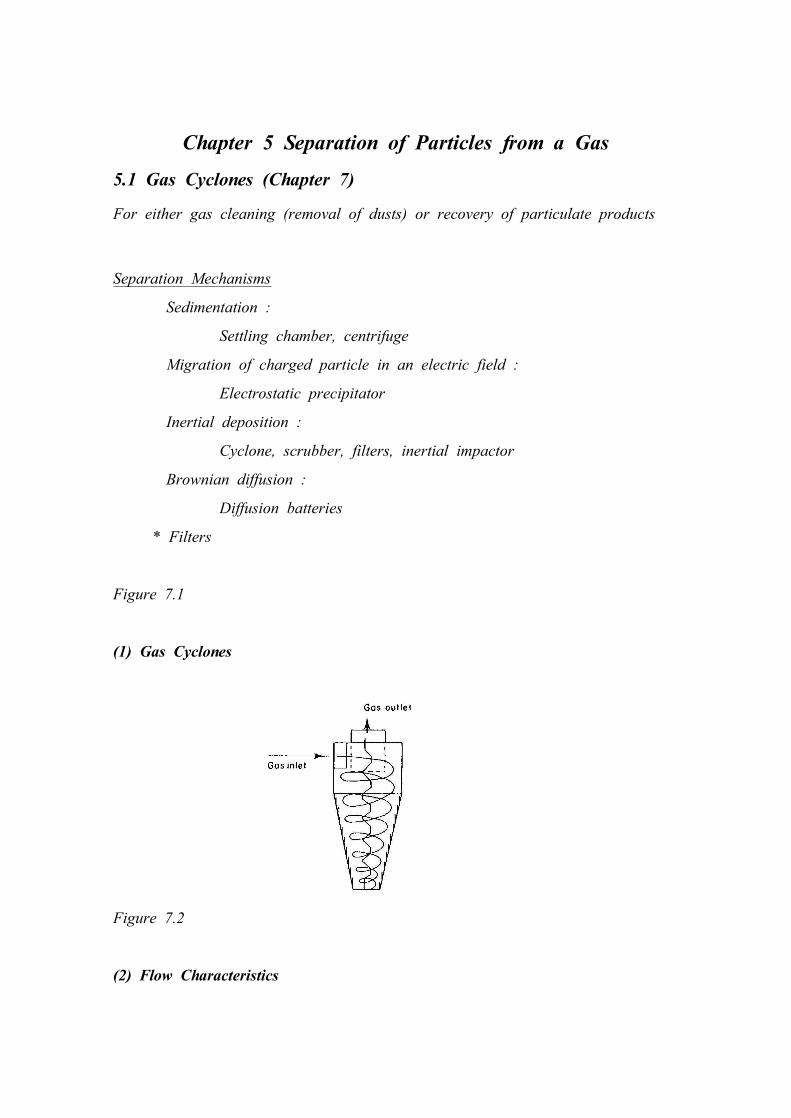
Chapter 5 Separation of Particles from a Gas 5.1 Gas Cyclones (Chapter 7) For either gas cleaning (removal of dusts) or recovery of particulate products Separation Mechanisms Sedimentation : Settling chamber, centrifuge Migration of charged particle in an electric field : Electrostatic precipitator Inertial deposition : Cyclone, scrubber, filters, inertial impactor Brownian diffusion : Diffusion batteries * Filters Figure 7.1 (1) Gas Cyclones Figure 7.2 (2) Flow Characteristics
Transcript of Chapter 5 Separation of Particles from a Gas...Chapter 5 Separation of Particles from a Gas 5.1 Gas...
Chapter 5 Separation of Particles from a Gas
5.1 Gas Cyclones (Chapter 7)
For either gas cleaning (removal of dusts) or recovery of particulate products
Separation Mechanisms
Sedimentation :
Settling chamber, centrifuge
Migration of charged particle in an electric field :
Electrostatic precipitator
Inertial deposition :
Cyclone, scrubber, filters, inertial impactor
Brownian diffusion :
Diffusion batteries
* Filters
Figure 7.1
(1) Gas Cyclones
Figure 7.2
(2) Flow Characteristics
- Rotational flow in the forced vortex in the cyclone body
→ radial pressure gradient
- Resistance coefficient: Euler number
Eu≡Δ p
ρ fv2/2
where v=4q
π D 2 ~pr essur e for ceiner t for ce
: cyclone inside diameter
* Economy of the collectors
Based on $/(1000 m3 cleaned gas /h)
annualized capital cost + operating cost* :
- Power requirement ≡ Q Δ p , [W]
where Δ p= f(L,v,ρ f,μ ) → Eu = f(Re p) ~ constant
By dimensional analysis for a given cyclone, independent of D
(3) Efficiency of Separation
1) Total Efficiency and Grade Efficiency
Total mass balance
M= M f+Mc
where M : total mass flow rate
M c : mass flow rate discharged from the solid exit orifice
(coarse product)
M f : solid mass flow rate leaving with the gas
(fine product)
Component mass balance
MdFdx
=Mf
dF f
dx+Mc
dF c
dx (*)

where dFdx
, dF c
dx,
dF f
dx : differential frequency size distributions
by mass for the feed, coarse product and fine product
Total efficiency, E T
E T =M c
M
Grade efficiency, G ( x)
G ( x) =m a ss of solids of size x in coa r se pr odu ct
m a ss of so lids of size x in feed
G( x)=M c
dF c
dx
MdFdx
= E T
dF c
dxdFdx
From (*)/
dFdx
= E T
dF c
dx+ (1-E T)
dF f
dx
In cumulative formF=E TF c+(1-E T)F f
2) Simple Theoretical Analysis for Gas Cyclone Separator
Figure 7.3
At equilibrium orbit, r
3π xμ U r =π x3
6(ρ p-ρ f)
U 2θ
r
F D FC-FB
where Uθ r 1/2= constant for confined vortex
= Uθ RR1/2
Urr =constant for radially inward flow
=URR
∴ x2 =18μ
ρ p-ρ f
U R
U 2θ R
r
where r : the radius of the equilibrium orbit (displacement) for a particle of diameter x
For all the particles to be collected, r≥R
x2cr it=
18μρ p-ρ f
U R
U 2θ R
R
where x c r it : critical(minimum) diameter of the particles to be collected
↓
or
If x > x c r i t , G ( x) = 1 and otherwise, G ( x) = 0
3) Cyclone Grade Efficiency in Practice
- Ideal grade efficiency curve Figure 7.4
Actual grade efficiency curve, "S"-shaped
: distorted due to velocity fluctuation and particle-particle interaction
* x 5 0 and St 50 in stead of x c r it and St cr it
where cut size, x 50≡ x at G ( x) = 0.5
(4) Scale-up of Cyclone
Cut diameter and pressure drop
- Dimensional analysis for G ( x)
G(d p)= f(x,ρ p,ρ f,L,v) → G(x)= f(St,Re,x/L)
where L : characteristic length of the separator
U : characteristic velocity of the particle
in the separator
St≡ρ px
2U
18μ L and Re≡
ρ fUL
μ
From G(x)= f(St,Re,x/L),
0.5= f(St50,Re,x/L)
or
St50= f 1(Re,x/L)
From both theoretical and actual analysis for given cyclone,
is independent of for a given cyclone geometry
St 50 (≡ρ px250U
18μ D ) ~ constan t → x50∝μ D 3/ρ pQ
↑ U=Q/π
4D 2
Similarly, from Eu =f 2(Re p )
is independent of for a given cyclone geometry
Eu (≡Δ p
ρ fU2/2 ) ∼ con sta n t → Δ p∝Q 2/D 4
↑ U=Q/π
4D 2
Standard Cyclone Designs - dimension
Figure 7.5
- High efficiency Stairmand cyclone:
St 50 = 1.4×10 - 4 and Eu = 320
- High flow rate Stairmand cyclone
St 50 = 6×10 - 3 and Eu = 46
Grade efficiency
G ( x) =( xx 50
)2
[ 1 + ( xx 50
)2
]for the geometry shown in p182
Figure 7.6
(5) Range of operation
Figure 7.7 : optimum operation somewhere between A and B
cf. Reentrainment
(6) Some Practical Design and Operation Details
U
Dj
StreamlineParticletrajectory
S
- High dust loading ( >~5g/m 3) → high separation efficiency
due to agglomeration
- For well-designed cyclone
Eu=12
Stk50
- Abrasion: gas inlet and particle outlet
lined with rubber, refractory lining or the materials
- Attrition: large particles with recirculation system
- Blockages: overloading, mechanical defects and water condensation
- Discharge hoppers(vortex breaker and stepped cone) and diplegs
(internal cyclone in fluidized bed)
- Cyclones in series: increasing recovery
N cyclones in parallel
For large gas flow rate
Q → Q/N
Worked Example 7.1
Worked Example 7.2
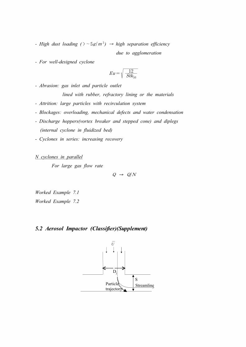
5.2 Aerosol Impactor (Classifier)(Supplement)
In general, for inertial motion of particles,
G ( x)= f (Stk( x),Re,SD j
)
where Stk( x) =τ ( x) UD
For given geometry ( S/D j)
0.5= f( Stk50,Re) → Stk 50 = f 1 (Re )
From numerical and/or experimental analysis
S tk( x) : almost independent of Re
Or for 500 < Re < 3000 and S/D > 1.5
For circular nozzle, Stk 50 = 0.22
For rectangular nozzle, Stk 50 = 0.53
∴ x 50 = [ 9μ DStk 50
ρ pUC c]1/2
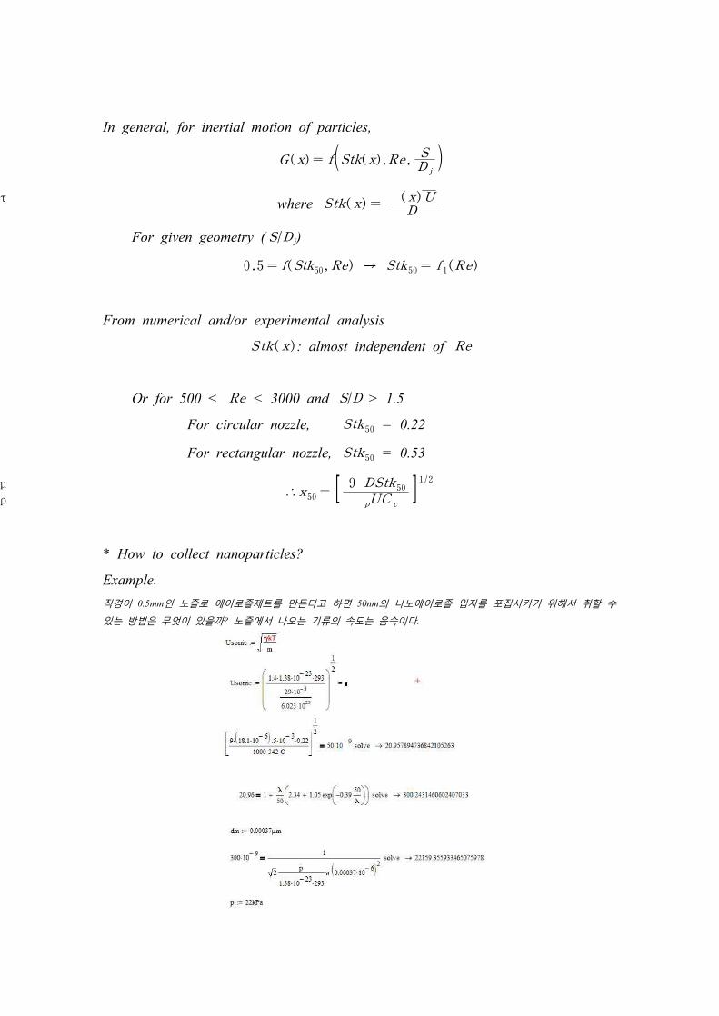
* How to collect nanoparticles?
Example.직경이 0.5mm인 노즐로 에어로졸제트를 만든다고 하면 50nm의 나노에어로졸 입자를 포집시키기 위해서 취할 수
있는 방법은 무엇이 있을까? 노즐에서 나오는 기류의 속도는 음속이다.
To filter
Particle-laden air
Stage 1
Stage 2
Stage 3
* Cascade impactor
- Measurement of particle size distribution
- Classification of particles
5.3 (Gas) Filtration
Filter materials - cellulose(wood), glass, plastic fibers
* High-temperature filters - metal. graphite, quartz, ceramic
(1) Air filters - depth filters
Filter Types
- Fibrous filters
- Membrane(porous) filters
- Capillary filters
Low solid loading ~mg/m3
e.g. Air-conditioning filters
- U∼0.25-1.5m/s, Δ p∼10- 1000Pa
HEPA(high efficiency particulate air) filter
- used in glove box, clean rooms, nuclear fuel industry
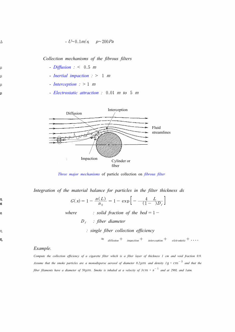
Impaction
InterceptionDiffusion
Cylinder orfiber
Fluidstreamlines
Three major mechanisms of particle collection on fibrous filter
- U∼0.1m/s, Δ p∼200Pa
Collection mechanisms of the fibrous filters
- Diffusion : < 0.5μ m
- Inertial impaction : > 1μ m
- Interception : > 1μ m
- Electrostatic attraction : 0.01μ m to 5μ m
Integration of the material balance for particles in the filter thickness dx
G( x)= 1-n (L )n 0
= 1- exp [- 4αη Lπ ( 1-α )D f
]where α : solid fraction of the bed = 1-ε
D f : fiber diameter
η : single fiber collection efficiency
η ≈η diffusion+η impaction+η inter ception+η elctr ostatic+....
Example.Compute the collection efficiency of a cigarette filter which is a fiber layer of thickness 1 cm and void fraction 0.9.
Assume that the smoke particles are a monodisperse aerosol of diameter 0.2 and density 1⋅ and that the
fiber filaments have a diameter of 50 . Smoke is inhaled at a velocity of 3⋅ and at 298L and 1atm.
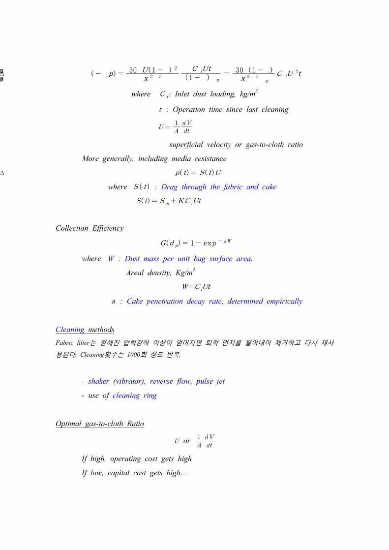
(2) Bag (fabric) filters - surface filters
Filter media : cylindrical bag type
- L/D ratio ~ 20, D ~ 120-150mm
- High solid loading ~g/m3
- Particle collection mechanisms
- Firstly, collection on individual fibers
Secondly, filtration by particle cake
Pressure drop
For shaking and reverse-flow filters
(-Δ p)H
=30μ U( 1 -ε ) 2
x 2ε 3
Since
(-Δ p) =30μ U( 1 -ε ) 2
x 2ε 3
C iUt
( 1 -ε )ρ p
=30μ ( 1 -ε )
x 2ε 3ρ p
C iU2t
where C i: Inlet dust loading, kg/m3
t : Operation time since last cleaning
≡
superficial velocity or gas-to-cloth ratio
More generally, including media resistance
Δ p( t)= S ( t)U
where S ( t ) : Drag through the fabric and cake
S( t)= S m+KC iUt
Collection Efficiency
G(d p) = 1- exp - aW
where W : Dust mass per unit bag surface area,
Areal density, Kg/m2
W=C iUt
a : Cake penetration decay rate, determined empirically
Cleaning methodsFabric filter는 정해진 압력강하 이상이 얻어지면 퇴적 먼지를 털어내어 제거하고 다시 재사
용된다. Cleaning횟수는 1000회 정도 반복.
- shaker (vibrator), reverse flow, pulse jet
- use of cleaning ring
Optimal gas-to-cloth Ratio
or
If high, operating cost gets high
If low, capital cost gets high...
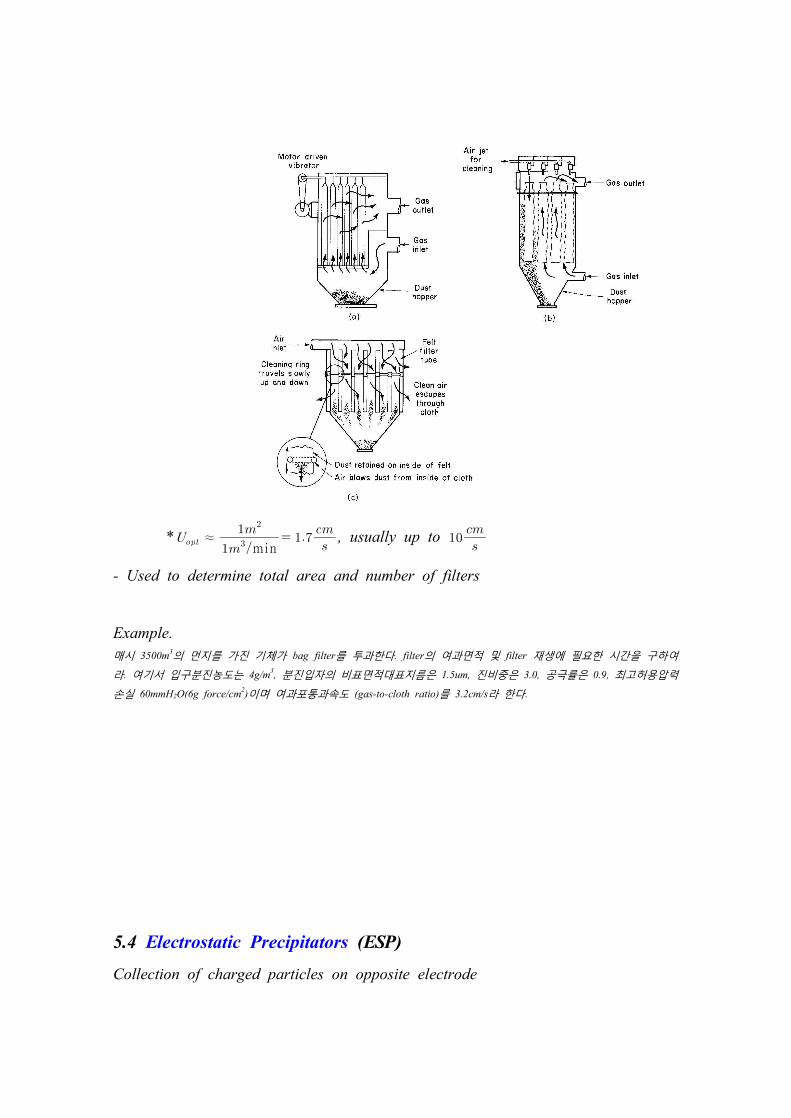
* ≈min
, usually up to
- Used to determine total area and number of filters
Example.매시 3500m3의 먼지를 가진 기체가 bag filter를 투과한다. filter의 여과면적 및 filter 재생에 필요한 시간을 구하여
라. 여기서 입구분진농도는 4g/m3, 분진입자의 비표면적대표지름은 1.5um, 진비중은 3.0, 공극률은 0.9, 최고허용압력
손실 60mmH2O(6g force/cm2)이며 여과포통과속도 (gas-to-cloth ratio)를 3.2cm/s라 한다.
5.4 Electrostatic Precipitators (ESP)
Collection of charged particles on opposite electrode
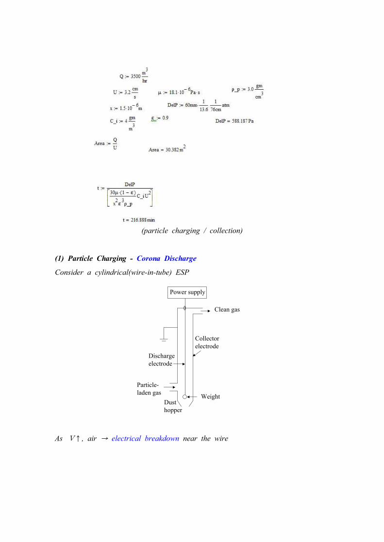
Dischargeelectrode
Collectorelectrode
Power supply
Particle-laden gas
Dusthopper
Weight
Clean gas
(particle charging / collection)
(1) Particle Charging - Corona Discharge
Consider a cylindrical(wire-in-tube) ESP
As V↑, air → electrical breakdown near the wire

Active zone
Passive zone
Wire, dischargeelectrode, +
Wall, collectorelectrode,-
Electrical fieldstrength
Distance
Positive corona Negative corona
Suitable for domestic application
-More stable than positive corona-Needs electron absorbing gas(SO2, O2, H2O)-Produces O3 as byproduct-Suitable for industrial applications
- Active zone → Active electrical breakdown
"Electron avalanche" - Blue glow
- Passive zone → Particle charging
* Charging mechanisms
- Field charging
- Diffusion charging
* Positive corona vs. negative corona
(2) Collection Efficiency
Assuming turbulent flow, U and n :uniform across cross sectional area
Choose : laminar sublayer wall thickness and such that
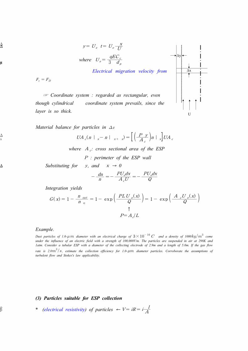
Dx
Dy
U
Δ y= U eΔ t= U eΔ x
U
where U e =qEC c
3πμ d p
Electrical migration velocity from
☞ Coordinate system : regarded as rectangular, even though cylindrical coordinate system prevails, since the layer is so thick.
Material balance for particles in
UA c (n ∣ x- n∣ x+Δ x) = [ ( PΔ yA c
)n∣ x]UA c
where A c: cross sectional area of the ESP
P : perimeter of the ESP wall Substituting for Δ y , and Δ x → 0
-dnn
=-PU edx
A cU=-
PU edx
Q
Integration yields
G ( x) = 1 -n ou t
n ∈
= 1- exp ( PLU e ( x)
Q )= 1- exp ( A cU e ( x)
Q )
↑P=A c/L
Example.Dust particles of 1.0- diameter with an electrical charge of × and a density of 1000 come under the influence of an electric field with a strength of 100,000V/m. The particles are suspended in air at 298K and 1atm. Consider a tubular ESP with a diameter of the collecting electrode of 2.9m and a length of 5.0m. If the gas flow
rate is 2.0 , estimate the collection efficiency for 1.0- diameter particles. Corroborate the assumptions of turbulent flow and Stokes's law applicability.
(3) Particles suitable for ESP collection
*ρ (electrical resistivity) of particles ← V= iR= iρ lA
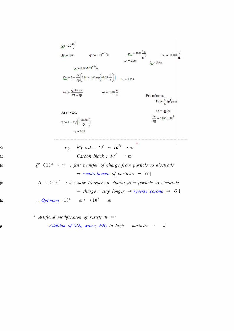
e.g. Fly ash : 106 ~ 1011Ω ⋅m
Carbon black : 10-5 Ω ⋅m
Ifρ < 10 2Ω ⋅m : fast transfer of charge from particle to electrode
→ reentrainment of particles → G↓
Ifρ > 2×10 8Ω ⋅m : slow transfer of charge from particle to electrode
→ charge : stay longer → reverse corona → G↓
∴ Optimum : 10 6Ω ⋅m <ρ < 10 8Ω ⋅m
* Artificial modification of resistivity ☞
Addition of SO3, water, NH3 to high-ρ particles → ρ ↓