
CHAPTER 4 EQUIPMENT AND INSTRUMENTATIONshodhganga.inflibnet.ac.in/bitstream/10603/35425/13/13...60...
10
60 CHAPTER 4 EQUIPMENT AND INSTRUMENTATION 4.1 SELECTION OF ENGINE The magnitude of the present fuel crisis in India is going to worsen in the foreseeable future due to significant increase of fuel consumption rate in the transportation and rural agriculture sector over the last few decades as well as due to steep increase in crude oil prices. Diesel engines are widely used in the agricultural sector as in tractors and irrigation pump sets. For the present work, the tests were conducted on a single cylinder, four stroke, naturally aspirated, air-cooled diesel engine coupled with electrical dynamometer test rig. The detailed technical specifications of the engine are given in Table 4.1. Figure 4.1 shows the schematic diagram of the experimental set-up. Table.4.1 Engine specifications Engine Type Four stroke, stationary, constant speed, direct injection, diesel engine Make Kirloskar Model TAF1 Maximum Power 4.4 kW @ 1500 RPM Maximum Torque 28 N-m @ 1500 RPM Bore 87.5 mm Stroke 110 mm Compression Ratio 17.5:1 Injection Timing 23.4 0 bTDC Loading Type Electrical Dynamometer
Transcript of CHAPTER 4 EQUIPMENT AND INSTRUMENTATIONshodhganga.inflibnet.ac.in/bitstream/10603/35425/13/13...60...

60
CHAPTER 4
EQUIPMENT AND INSTRUMENTATION
4.1 SELECTION OF ENGINE
The magnitude of the present fuel crisis in India is going to worsen in
the foreseeable future due to significant increase of fuel consumption rate in
the transportation and rural agriculture sector over the last few decades as well
as due to steep increase in crude oil prices. Diesel engines are widely used in
the agricultural sector as in tractors and irrigation pump sets.
For the present work, the tests were conducted on a single cylinder,
four stroke, naturally aspirated, air-cooled diesel engine coupled with
electrical dynamometer test rig. The detailed technical specifications of the
engine are given in Table 4.1. Figure 4.1 shows the schematic diagram of the
experimental set-up.
Table.4.1 Engine specifications
Engine Type Four stroke, stationary, constantspeed, direct injection, diesel engine
Make KirloskarModel TAF1
Maximum Power 4.4 kW @ 1500 RPMMaximum Torque 28 N-m @ 1500 RPM
Bore 87.5 mmStroke 110 mm
Compression Ratio 17.5:1Injection Timing 23.40 bTDC
Loading Type Electrical Dynamometer

61
Fig. 4.1: Layout of engine test rig
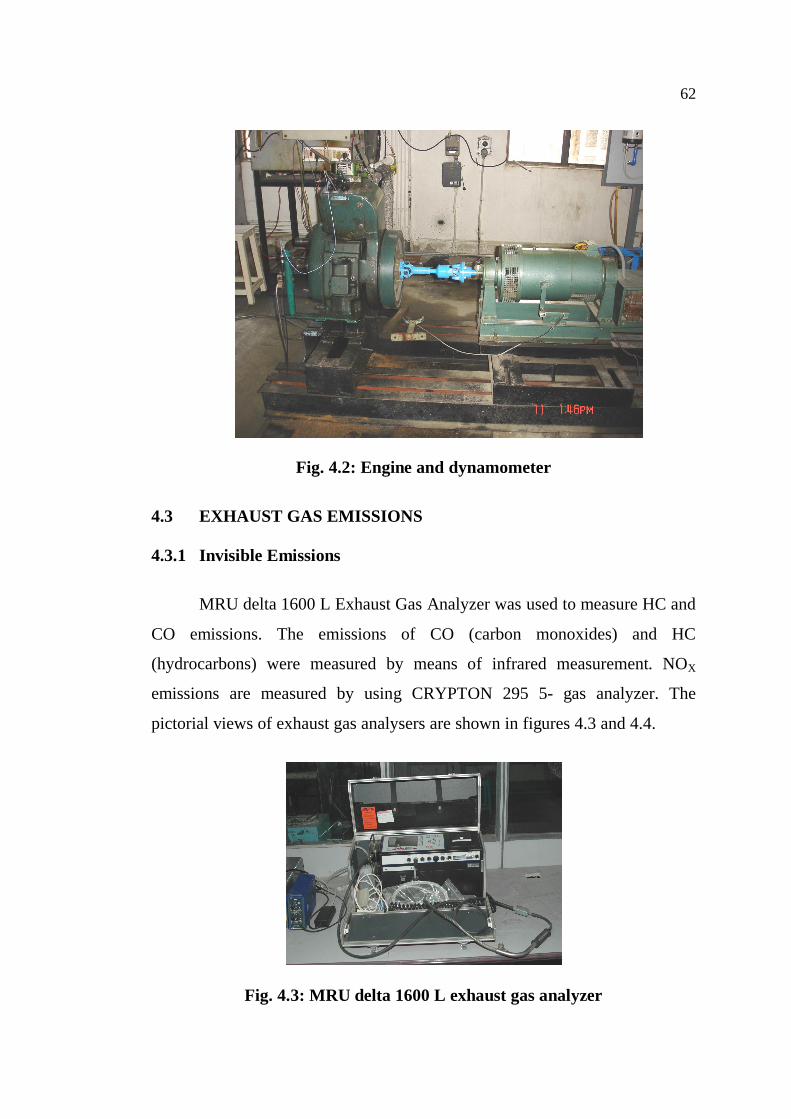
4.2 DYNAMOMETER
Electrical swinging field dynamometer is used for measuring the brake
power of the engine. This dynamometer is coupled to the engine by flexible
coupling. This electrical dynamometer consists of a 5 KVA AC alternator
(220V, 1500rpm) mounted on the bearings and on the rigid frame for the
swinging field type loading. The output power is directly obtained by
measuring the reaction torque. Reaction force (torque) is measured by using a
strain gauge type load cell. A water rheostat is used to dissipate the power
generated. A panel board consisting of ammeter, voltmeter, switches and fuse,
load cell indicator, digital rpm readout etc, is also provided. Figure 4.2 shows
pictorial view of engine and dynamometer.
62
Fig. 4.2: Engine and dynamometer
4.3 EXHAUST GAS EMISSIONS
4.3.1 Invisible Emissions
MRU delta 1600 L Exhaust Gas Analyzer was used to measure HC and
CO emissions. The emissions of CO (carbon monoxides) and HC
(hydrocarbons) were measured by means of infrared measurement. NOX
emissions are measured by using CRYPTON 295 5- gas analyzer. The
pictorial views of exhaust gas analysers are shown in figures 4.3 and 4.4.
Fig. 4.3: MRU delta 1600 L exhaust gas analyzer

63
Fig. 4.4: CRYPTON 295 5- gas analyzer
4.3.2 Visible Emissions
AVL 415 Variable Sampling Smoke meter was used to measure the
particulate matter in the exhaust. The part of the exhaust gas flow was
sampled by means of a probe in the exhaust line and drawn through a filter
paper. The resultant blackening of the filter paper was measured by a
reflectometer and hence the soot content in the exhaust gas was determined.
The pictorial view of smoke meter is shown in figure.4.5.
Fig. 4.5: AVL 415 Variable sampling smoke meter

64
4.4 COMBUSTION CHAMBER PRESSURE
Engine cylinder pressure is the basic parameter, necessary for any type
of engine combustion analysis. Cylinder pressure changes with crank angle as
a result of cylinder volume change, combustion, heat transfer to the walls,
flow into and out of the crevice regions and leakage. The combustion rate
information can be obtained from accurate pressure data.
4.4.1 Pressure Transducer
Cylinder pressure is measured using AVL pressure transducer. The
pressure transducer is located in a hole drilled through the cylinder head into
the combustion chamber. The sensing element consists of metal diaphragm,
which deflects under pressure. This deflection is converted into voltage, which
is proportional to pressure. The pictorial view of pressure transducer is shown
in fig.4.6. The pressure transducer is fitted in to the combustion chamber
through the cylinder head as shown in figure.4.7.
Make : AVL
Model : GH12D Miniature Pressure Transducer
Measuring Range : 0...250 bar (25 Mpa)
Sensitivity : 15 pC/bar (150 pC/Mpa)
Temperature Range : up to 400°C
The soot deposits occur on the surface of pressure transducer
diaphragm is lead to an error margin of upto 10%. In order to avoid this, it is
necessary to clean the transducer after every 10 hours of operation. 10% -
15% solution of caustic soda (NaOH) is used as cleaning solution and non-
ionic tansies are used as cleaning agent. The transducer is immersed in the

65
bath for 5-8 hours and then dried in an oven at 40oC to 50oC to remove the
vapour.
Fig. 4.6: Pressure transducer
Fig. 4.7: Pressure transducer in mounted position

66
4.4.2 Angle Encoder
Angle Encoder is used to convert the analog value of angle into digital,
electrical signal. Counters, microprocessors or data processing equipment can
be connected to the encoder to evaluate these electrical signals and determine
the angular position and the speed of revolution. This is fitted carefully on the
crankshaft and CDM conditioner (AVL 3016a01) in conjunction with encoder
is intended to trigger signal and crank marker conditioning. CDM conditioner
is prepared for conditioning 600 input pulses per revolution. The angle
encoder in mounted position is shown in figure.4.8.
Make : AVL
Model : AVL 364 angle encoder
Measuring Range : 10 … 15000 min-1
Resolution : 0.5 deg. CA
Temperature Range : -30°C to +100°C for encoder at mounting surface
Fig. 4.8 : Angle encoder
67
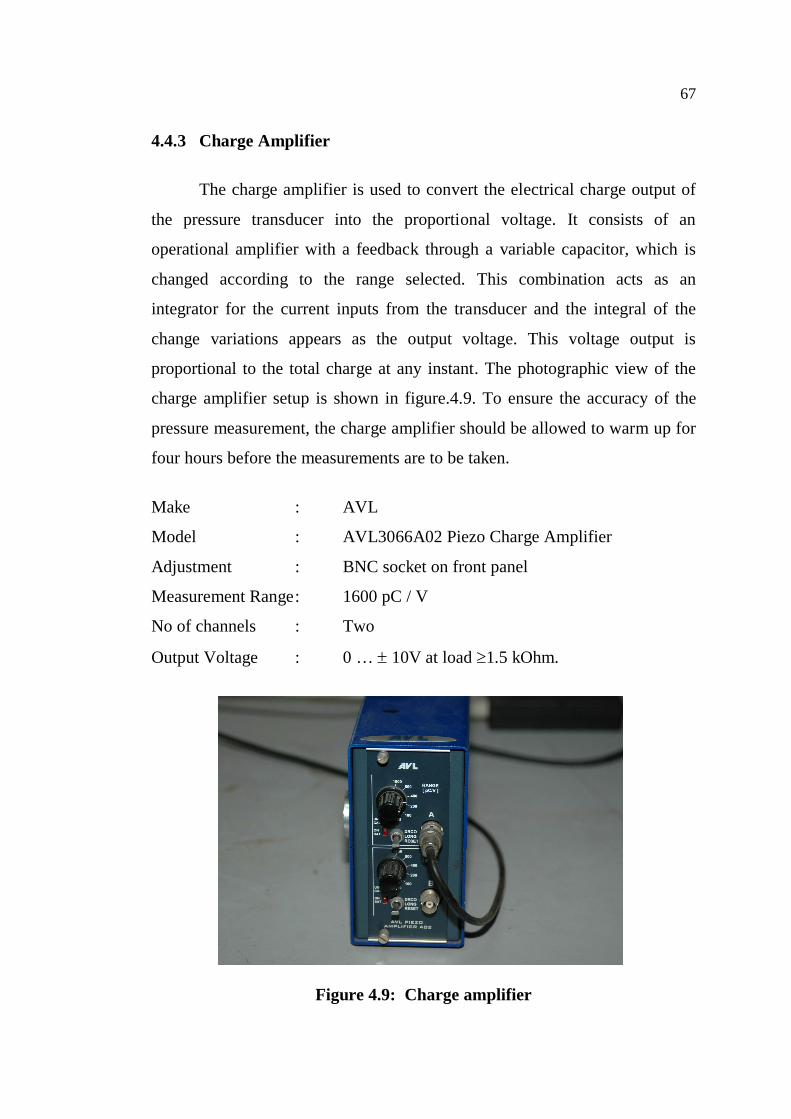
4.4.3 Charge Amplifier
The charge amplifier is used to convert the electrical charge output of
the pressure transducer into the proportional voltage. It consists of an
operational amplifier with a feedback through a variable capacitor, which is
changed according to the range selected. This combination acts as an
integrator for the current inputs from the transducer and the integral of the
change variations appears as the output voltage. This voltage output is
proportional to the total charge at any instant. The photographic view of the
charge amplifier setup is shown in figure.4.9. To ensure the accuracy of the
pressure measurement, the charge amplifier should be allowed to warm up for
four hours before the measurements are to be taken.
Make : AVL
Model : AVL3066A02 Piezo Charge Amplifier
Adjustment : BNC socket on front panel
Measurement Range : 1600 pC / V
No of channels : Two
Output Voltage : 0 … 10V at load 1.5 kOhm.
Figure 4.9: Charge amplifier

68
4.4.4 Combustion Analyser
In this work, AVL 615 Indimeter system was used to analyse
combustion chamber pressure data. AVL Indimeter consists of A/D card to
convert analog signal into digital signals. These digital signals form the input
to the AVL Indimeter software. This software analyses the data and is capable
of producing pressure-crank angle diagram, log p-v diagram and heat release
rate.
4.5 TEST PROCEDURE
Before starting the experiments, all the equipments were calibrated
according to the manufacturers’ guidelines. The engine was started by hand
cranking and was allowed to warm up at no load condition. The engine was
fueled with methyl ester, traditional diesel and blends containing 20 percent,
40 percent, 60 percent and 80 percent of methyl ester. For every fuel change,
the fuel lines were cleaned, and the engine was left to operate undisturbed for
at least 30 minutes to stabilize on the new conditions. The following
measurements were made at various loads (0%, 25%, 50%, 75% and 100% of
rated load).
1. Fuel consumption
2. Air flow rate
3. Engine output
4. In cylinder pressure data
5. Engine emissions

69
4.6 ERROR ANALYSIS
The errors associated with various primary experimental measurements
and the calculations of performance parameters are detailed in Appendix 1.
The summary of estimated uncertainties is given in table.4.2.
Table 4.2 Summary of estimated uncertainties
Parameters Uncertainty (%)
Reaction temperature 0.249
Exhaust gas temperature 0.41
Pressure 2.0
Brake thermal efficiency 0.31
HC 5.0
CO 5.0
NOx 5.0
Smoke intensity 5.0


