Chapter 3 Actuators and output...
24
Festo Didactic • TP101 155 Chapter B-3 Chapter 3 Actuators and output devices
Transcript of Chapter 3 Actuators and output...

Festo Didactic • TP101
155 Chapter B-3
Chapter 3
Actuators and output devices

TP101 • Festo Didactic
156 Chapter B-3
An actuator is an output device for the conversion of supply energy into useful work. The output signal is controlled by the control system, and the actuator responds to the control signals via the control element. Other types of output devices are used to indicate the status of the con-trol system or actuators, e.g. a pneumatically actuated visual display. The pneumatic actuator can be described under two groups, linear and rotary : ! Linear motion
� Single-acting cylinders � Double-acting cylinders
! Rotary motion � Air motor � Rotary cylinders � Rotary actuator
3.1 Single-acting cylinders
With single-acting cylinders compressed air is applied on only one side of the piston face. The other side is open to atmosphere. The cylinder can produce work in only one direction. The return movement of the pis-ton is effected by a built-in spring or by the application of an external force. The spring force of the built-in spring is designed to return the piston to its start position with a reasonably high speed under no load conditions.
Fig.3.1 Single-acting cylinder

Festo Didactic • TP101
157 Chapter B-3
For single-acting cylinders with built-in spring, the stroke is limited by the natural length of the spring. Single-acting cylinders are therefore only available in stroke lengths of up to approximately 80 mm. The construction and simplicity of operation of the single-acting cylinder makes it particularly suitable for compact, short stroke length cylinders for the following types of applications: ! Transferring ! Branching ! Converging ! Allocating ! Clamping ! Ejecting The single-acting cylinder has a single piston seal which is fitted on the air supply side. Sealing is by a flexible material that is embedded in a metal or plastic piston (Perbunan). During motion, the sealing edges slide over the cylinder bearing surface. There are varying designs of single-acting cylinders including: ! Diaphragm cylinder ! Rolling diaphragm cylinder With a diaphragm cylinder, a built-in diaphragm made of rubber, plastic or metal performs the task of the piston. The piston rod is mounted cen-trally on the diaphragm. There is no sliding seal, but merely friction as a result of the tensile stress of the diaphragm. They are used in short stroke applications, for clamping, embossing and lifting operations.
Construction
Fig. 3.2 Diaphragm cylinder

TP101 • Festo Didactic
158
Chapter B-3
3.2 Double-acting cylinders
The construction principle of a double-acting cylinder is similar to that of the single-acting cylinder. However, there is no return spring, and the two ports are used alternatively as supply and exhaust ports. The dou-ble-acting cylinder has the advantage that the cylinder is able to carry out work in both directions of motion. Thus, installation possibilities are universal. The force transferred by the piston rod is somewhat greater for the forward stroke than for the return stroke as the effective piston surface is reduced on the piston rod side by the cross-sectional area of the piston rod.
Pneumatic cylinders have developed in the following directions:
� Contactless sensing requirements - hence the use of magnets on pistons for reed switch operation
� Stopping heavy loads
� Rodless cylinders where space is limited
� Alternative manufacturing materials such as plastic
� Protective coatings against harsh environments, i.e. acid-resistant
� Increased load carrying capacity
� Robotic applications with special features such as non-rotating pis-ton rods, hollow piston rods for vacuum suction cups
Fig. 3.3 Double-acting cylinder
Design development
Festo Didactic • TP101
159 Chapter B-3
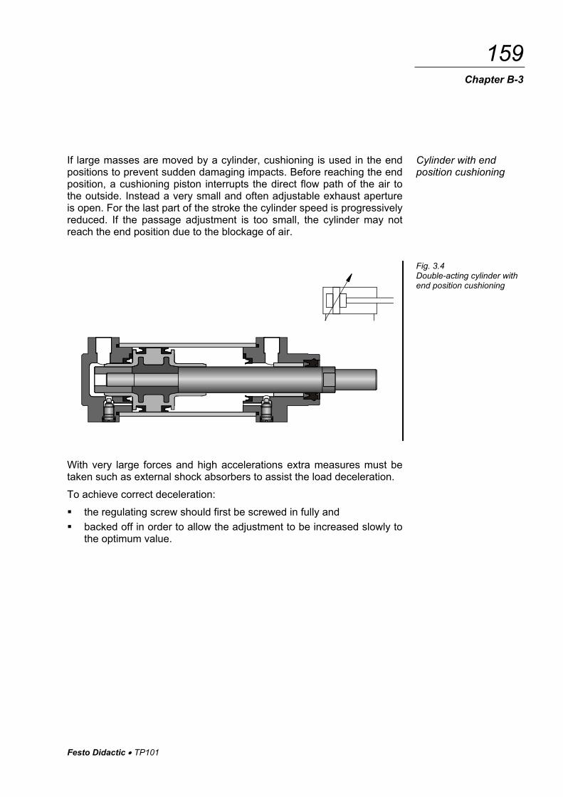
If large masses are moved by a cylinder, cushioning is used in the end positions to prevent sudden damaging impacts. Before reaching the end position, a cushioning piston interrupts the direct flow path of the air to the outside. Instead a very small and often adjustable exhaust aperture is open. For the last part of the stroke the cylinder speed is progressively reduced. If the passage adjustment is too small, the cylinder may not reach the end position due to the blockage of air.
With very large forces and high accelerations extra measures must be taken such as external shock absorbers to assist the load deceleration. To achieve correct deceleration: ! the regulating screw should first be screwed in fully and ! backed off in order to allow the adjustment to be increased slowly to
the optimum value.
Cylinder with end position cushioning
Fig. 3.4 Double-acting cylinder with end position cushioning

TP101 • Festo Didactic
160
Chapter B-3
The tandem cylinder incorporates the features of two double-acting cyl-inders which have been joined to form a single unit. By this arrangement and with the simultaneous loading of both pistons, the force on the pis-ton rod is almost doubled. This design is suitable for such applications where a large force is required but the cylinder diameter is restricted.
This cylinder has a piston rod on both sides, which is a through piston rod. The guide of the piston rod is better, as there are two bearing points. The force is identical in both directions of movement.
The through piston rod can be hollow, in which case it can be used to conduct various media, such as compressed air. A vacuum connection is also possible.
Tandem double-acting cylinder
Fig. 3.5 Tandem
double-acting cylinder
Cylinders with through piston rod
Fig. 3.6 Cylinders with
through piston rod

Festo Didactic • TP101
161 Chapter B-3
The multiposition cylinder consists of two or several double-acting cylin-ders, which are interconnected. The individual cylinders advance when pressure is applied. In the case of two cylinders with different stroke lengths, four positions are obtained.
The pressure forces of pneumatic cylinders are limited. One cylinder for high kinetic energy is the impact cylinder. The high kinetic energy is achieved by means of increasing the piston speed. The piston speed of the impact cylinder is between 7.5 m/s and 10 m/s. However, in the case of large forming distances, the speed is rapidly reduced. The impact cylinder is therefore not suitable for large forming distances.
Multiposition cylinders
Fig. 3.7 Multiposition cylinders
Impact cylinders
Fig. 3.8 Impact cylinders

TP101 • Festo Didactic
162
Chapter B-3
Actuation of a valve causes pressure to build up in chamber A. If the cylinder moves in direction Z, the full piston surface is exposed. The air from chamber A is able to flow quickly via the large cross section C. The piston is greatly accelerated.
With this design of double-acting cylinder, the piston rod has a gear-tooth profile. The piston rod drives a gear wheel, and a rotary movement results from a linear movement. The range of rotation varies from 45o, 90o, 180o, 270o to 360o. The torque is dependent on pressure, piston surface and gear ratio; values of roughly up to 150 Nm are possible.
Rotary cylinders
Fig. 3.9 Rotary cylinders

Festo Didactic • TP101
163 Chapter B-3
With a rotary actuator, force is transmitted direct to the drive shaft via a vane. Angular displacement is infinitely adjustable from 0o to approx. 180o. Torque should not exceed 10 Nm.
Design features of pneumatic rotary actuators: ! Small and robust ! Available with contactless sensing ! Adjustable for angular displacement ! Easy to install
Rotary actuator
Fig. 3.10 Rotary actuator

TP101 • Festo Didactic
164
Chapter B-3
3.3 Rodless cylinders
Three different operational principles are used for the construction of rodless cylinders:
� Band or cable cylinder
� Sealing band cylinder with slotted cylinder barrel
� Cylinder with magnetically coupled slide
Compared with conventional double-acting cylinders, rodless cylinders are shorter in length. This eliminates the risk of a buckling piston rod and movement can take place over the entire stroke length. The cylinder design can be used for extremely large cylinder lengths of up to 10 m. Devices, loads etc, can be attached directly to the mounting surface pro-vided for this on a carriage or outer slide. The force is identical in both directions of movement.
In the case of band cylinders, the piston force is transferred to a slide via a circulating band. When leaving the piston chamber, the band passes through a seal. In the cylinder caps, the band is reversed via guide roll-ers. Wipers ensure that no contamination reaches the guide rollers via the band.
Band cylinder
Fig. 3.11 Band cylinder

Festo Didactic • TP101
165
Chapter B-3
With this type, the cylinder barrel is provided with a slot across the entire length. The force is transmitted via a slide permanently connected to the piston. The connection from piston to slide is directed outwards via the slotted cylinder barrel. The slot is sealed by means of a sealing band, which seals the inside of the slot. The sealing band is guided between the piston seals and passed under the slide. A second cover strip covers the slot from the outside in order to prevent the ingress of dirt.
Sealing band cylinder
Fig. 3.12 Sealing band cylinder

TP101 • Festo Didactic
166 Chapter B-3
This double-acting pneumatic linear actuator (rodless cylinder) consists of a cylindrical barrel, a piston and 2 slide. The piston in the cylinder is freely movable according to pneumatic actuation, but there is no positive external connection. The piston and the slide are fitted with a set of an-nular permanent magnets. Thus, a magnetic coupling is produced be-tween slide and piston. As soon as the piston is moved by compressed air the slide moves synchronously with it. The cylinder barrel is hermeti-cally sealed from the outer slide since there is no mechanical connec-tion. There are no leakage losses.
Cylinder with magnetic coupling
Fig. 3.13 Cylinder with
magnetic coupling

Festo Didactic • TP101
167 Chapter B-3
3.4 Cylinder construction
The cylinder consists of a cylinder barrel, bearing and end cap, piston with seal (double-cup packing), piston rod, bearing bush, scraper ring, connecting parts and seals.
The cylinder barrel (1) is usually made of seamless drawn steel tube. To increase the life of the sealing components, the bearing surfaces of the cylinder barrel are precision-machined. For special applications, the cyl-inder barrel can be made of aluminium, brass or steel tube with hard-chromed bearing surface. These special designs are used where opera-tion is infrequent or where there are corrosive influences. The end cap (2) and the bearing cap (3) are, for the most part, made of cast material (aluminium or malleable cast iron). The two caps can be fastened to the cylinder barrel by tie rods, threads or flanges. The piston rod (4) is preferably made from heat-treated steel. A certain percentage of chrome in the steel protects against rusting. Generally the threads are rolled to reduce the danger of fracture. A sealing ring (5) is fitted in the bearing cap to seal the piston rod. The bearing bush (6) guides the piston rod and may be made of sintered bronze or plastic-coated metal. In front of this bearing bush is a scraper ring (7). It prevents dust and dirt particles from entering the cylinder space. Bellows are therefore not normally required.
Fig. 3.14 Design of a pneumatic cylinder with end position cushioning

TP101 • Festo Didactic
168
Chapter B-3
The materials for the double-cup packing seals (8) are:
Perbunan for – 20 °C to + 80 °C Viton for – 20 °C to + 150 °C Teflon for – 80 °C to + 200 °C
0-rings (9) are normally used for static sealing.
Fig. 3.15 Cylinder seals

Festo Didactic • TP101
169
Chapter B-3
The type of mounting is determined by the manner in which the cylinder is to be fitted to a machine or fixture. The cylinder can be designed with a permanent type of mounting if it does not have to be altered at any time. Alternatively, the cylinder can utilise adjustable types of mounting which can be altered at a later date by using suitable accessories on the modular construction principle. This results in considerable simplification in storage, especially where a large number of pneumatic cylinders are used as only the basic cylinder and optional mounting parts need to be stored.
The cylinder mounting and the piston rod coupling must be matched carefully to the relevant application since cylinders must be loaded only in the axial direction.
Mounting
Fig. 3.16 Mounting arrangements for cylinders

TP101 • Festo Didactic
170 Chapter B-3
As soon as force is transmitted to a machine, stresses occur at the cyl-inder. If shaft mismatching and misalignments are present, bearing stresses at the cylinder barrel and piston rod can also be expected. The consequences are : ! High edge pressures on the cylinder bearing bushes leading to in-
creased wear ! High edge pressures on the piston rod guide bearings ! Increased and uneven stresses on piston rod seals and piston seals. ! With large cylinder strokes, the buckling load of the piston rod should
be observed
3.5 Cylinder performance characteristics
Cylinder performance characteristics can be determined theoretically or by the use of manufacturer�s data. Both methods are acceptable, but in general the manufacturer's data is more relevant to a particular design and application. The piston force exerted by the cylinder is dependent upon the air pres-sure, the cylinder diameter and the frictional resistance of the sealing components. The theoretical piston force is calculated by the formula:
Fth = A • p Fth = Theoretical piston Force (N) A = Useful piston Area (m2) p = Operating Pressure (Pa) In practice, the effective piston force is significant. When calculating this, frictional resistance should be taken into consideration. Under normal operating conditions (pressure range of 400 to 800 kPa / 4 to 8 bar) fric-tional force of approx. 10% of the theoretical piston force can be as-sumed. Single-acting cylinder
Feff = (A • p) - (FR + FF)
Piston force

Festo Didactic • TP101
171 Chapter B-3
Double-acting cylinders
Forward stroke Feff = (A • p) - FR Return stroke Feff = (A' • p) - FR Feff = effective piston force (N) A = useful piston surface (m2)
= )(4
D2 π•
A' = useful annular surface (m2)
= 4
)d(D 22 π−
p = Working pressure (Pa) FR = Frictional force (approx. 10 % of Fth) (N) FF = Return spring force (N) D = Cylinder diameter (m) d = Piston rod diameter (m).
Fig. 3.17 Pressure vs. force diagram

TP101 • Festo Didactic
172
Chapter B-3
The stroke lengths of pneumatic cylinders should not be greater than 2 m and for rodless cylinders 10 m.
With excessive stroke lengths the mechanical stress on the piston rod and on the guide bearings would be too great. To avoid the danger of buckling, the buckling diagram should be observed with large stroke lengths.
Stroke length
Fig. 3.18 Buckling diagram

Festo Didactic • TP101
173 Chapter B-3
The piston speed of pneumatic cylinders is dependent on the load, the prevailing air pressure, the length of pipe, the cross-sectional area of the line between the control element and the working element and also the flow rate through the control element. In addition, the speed is influenced by the end position cushioning. The average piston speed of standard cylinders is about 0.1-1.5 m/sec. With special cylinders (impact cylinders), speeds of up to 10 m/sec are attained. The piston speed can be regulated by one way flow control valves and speed increased by the use of quick exhaust valves.
Piston speed
Fig. 3.19 Average piston speed

TP101 • Festo Didactic
174
Chapter B-3
For the preparation of the air, and to obtain facts concerning power costs, it is important to know the air consumption of the system. The air consumption is specified in litres of air drawn in per minute. For a par-ticular operating pressure, piston diameter, stroke and stroke number, the air consumption is calculated by:
Air consumption =
Compression ratio • Piston surface • Stroke • Stroke number per minute
Compression ratio = 101.3
kPa)(inpressureOperating101.3 +
The formulae for the calculation of air consumption in accordance with the air consumption diagram are as follows:
for single-acting cylinders
qB = s • n • qH
for double-acting cylinders
qB = 2 • s • n • qH qB = Air consumption (l/min) s = Stroke (cm) n = Number of strokes per minute (1/min) qH = Air consumption per cm of stroke (l/cm)
Air consumption
Fig. 3.20 Air consumption chart

Festo Didactic • TP101
175 Chapter B-3
With these formulae, the varying air consumption of double-acting cylin-ders during forward and return stroke are not taken into consideration. This can be disregarded due to the different tolerances in lines and valves. The overall air consumption of a cylinder also includes the filling of dead zones. The air consumption required to fill dead zones can be up to 20% of the air consumption. Dead zones of a cylinder are compressed air supply lines in the cylinder itself and not zones in the end positions of the piston which are effective for the stroke.
Piston diameter
in mm
Cover side in cm3
Base side in cm3
Piston diameter
in mm
Cover sidein cm3
Base sidein cm3
12 1 0.5 70 27 31
16 1 1.2 100 80 88
25 5 6 140 128 150
35 10 13 200 425 448
50 16 19 250 2005 2337
T 3.1 Dead zones of cylinders (1000 cm³ = 1l)

TP101 • Festo Didactic
176
Chapter B-3
3.6 Motors
Devices which transform pneumatic energy into mechanical rotary movement with the possibility of continuous motion are known as pneu-matic motors. The pneumatic motor with unlimited angle of rotation has become one of the most widely used working elements operating on compressed air. Pneumatic motors are categorised according to design:
� Piston motors
� Sliding-vane motors
� Gear motors
� Turbines (high flow)
This type of design is further subdivided into radial and axial piston mo-tors. The crank shaft of the motor is driven by the compressed air via reciprocating pistons and connecting rods. To ensure smooth running several pistons are required. The power of the motor depends on input pressure, number of pistons, piston area, stroke and piston speed.
The working principle of the axial piston motor is similar to that of the radial piston motor. The force from 5 axially arranged cylinders is con-verted into a rotary motion via a swash plate. Compressed air is applied to two pistons simultaneously, the balanced torque providing smooth running of the motor.
These pneumatic motors are available in clockwise or anti-clockwise rotation. The maximum speed is around 5000 rpm, the power range at normal pressure being 1.5 - 19 kW (2 - 25 hp).
Fig. 3.21 Air motor
Piston motors

Festo Didactic • TP101
177 Chapter B-3
Because of their simple construction and the low weight, sliding vane motors are used for hand tools. An eccentric rotor is contained in bearings in a cylindrical chamber. Slots are arranged in the rotor. The vanes are guided in the slots of the rotor and forced outwards against the inner wall of the cylinder by centrifugal force. With other designs, the vanes are moved via springs. This en-sures that the individual chambers are sealed. The rotor speed is be-tween 3000 and 8500 rpm. Here too, clockwise or anti-clockwise units are available. Power range 0.1 - 17 kW (0.14 - 24 hp). In this design, torque is generated by the pressure of the air against the teeth profiles of two meshed gear wheels. One of the gear wheels is secured to the motor shaft. Gear motors are produced with spur or heli-cal gearing. These gear motors are used in applications with a very high power rating ( up to 44 kW/60 hp). The direction of rotation is also re-versible for these motors. Turbine motors can be used only where a low power is required. The speed range is very high. For example, the Dentists' air drill operates at 500,000 rpm. The working principle is the reverse of the flow compres-sor. Characteristics of pneumatic motors are: ! Smooth regulation of speed and torque ! Small size (weight) ! Overload safe ! Insensitive to dust, water, heat, cold ! Explosion proof ! Large speed selection ! Maintenance minimal ! Direction of rotation easily reversed
Sliding vane motors
Gear motors
Turbines (flow motors)

TP101 • Festo Didactic
178 Chapter B-3
3.7 Indicators
Optical indicators visually represent the operating status of the pneu-matic system and serve as diagnostic aids. Some of the visual devices are: ! Counters, for displaying counting cycles ! Pressure gauges, to indicate air pressure values ! Timers, with visual indication of time delay ! Optical indicators With the optical indicators the colour codes represent certain functions in the cycle. The visual indicators are mounted on the control panel to indi-cate status of control functions and the sequential steps currently active. The colours for visual indicators in accordance with VDE 0113 are:
Colour Meaning Notes
Red Immediate danger, alarm Machine status or situations requiring immediate intervention.
Yellow Caution Change or imminent change of condi-tions.
Green Start, on Normal operation, safe situation, free entry
Blue Special information Special meaning which cannot be made clear by red, yellow or green.
White or Clear General information Without special meaning. Can also be used in cases where there is doubt as to the suitability of the three colours red, yellow or green.
Optical indicators
T 3.2 Optical indicators


![Sensors and Actuators B: Chemicalfaculty.iitmandi.ac.in/~satinder/files/Journals/45.pdf · sensors, micro-interdigitated electrodes ( -IDEs) are employed extensively [13]. The output](https://static.fdocuments.net/doc/165x107/5f5dda269910e76c92579ae2/sensors-and-actuators-b-satinderfilesjournals45pdf-sensors-micro-interdigitated.jpg)