CHAPTER 22CHAPTER 22 Geotechnical Aspects in Maintenance Matters NYSDOT Geotechnical Page 22-13 July...
43
NYSDOT Geotechnical Page 22-1 July 18, 2013 Design Manual GEOTECHNICAL DESIGN MANUAL CHAPTER 22 GEOTECHNICAL ASPECTS IN MAINTENANCE MATTERS
Transcript of CHAPTER 22CHAPTER 22 Geotechnical Aspects in Maintenance Matters NYSDOT Geotechnical Page 22-13 July...

NYSDOT Geotechnical Page 22-1 July 18, 2013
Design Manual
GEOTECHNICAL DESIGN MANUAL
CHAPTER 22
GEOTECHNICAL ASPECTS IN
MAINTENANCE MATTERS

NYSDOT Geotechnical Page 22-2 July 18, 2013
Design Manual
(Intentionally left blank)

Table of Contents
NYSDOT Geotechnical Page 22-3 July 18, 2013
Design Manual
22.1 OVERVIEW .................................................................................................................. 22-4
22.1.1 Disclaimer .......................................................................................................... 22-4
22.2 UNDERSTANDING THE SIGNS OF MOVEMENT .................................................. 22-5
22.3 THE EROSIVE ACTION OF WATER ....................................................................... 22-13
22.3.1 Sheet, Rill, and Gulley Erosion of Sideslopes .............................................. 22-14
22.3.2 Groundwater Seepage Affecting Sideslopes ................................................. 22-19
22.3.3 Groundwater Conflicts Affecting Pavements ............................................... 22-24
22.3.4 Stream or Overland Flow Scouring .............................................................. 22-28
22.4 DETERIORATION OF HIGHWAY SLOPES ............................................................ 22-34
22.4.1 Shoulder Back-Up Fixes ............................................................................... 22-34
22.4.2 Rockfalls ....................................................................................................... 22-38
22.4.2.1 Rockfall Database - The Rock Slope Inventory ................................ 22-38
22.4.3 Problem Soil Slopes ...................................................................................... 22-41
22.4.3.1 The Earth Slope Inventory ................................................................ 22-41
22.4.4 Sink Holes ..................................................................................................... 22-42
22.4.4.1 Grouting ............................................................................................ 22-42
22.5 REFERENCES ............................................................................................................ 22-43
CHAPTER 22
Geotechnical Aspects in Maintenance Matters
NYSDOT Geotechnical Page 22-4 July 18, 2013
Design Manual
22.1 OVERVIEW
The NYSDOT’s Regional Transportation Maintenance Groups are organizations committed to
providing a safe, reliable transportation system by endeavoring to remedy the effects of a snow
storm, hurricane, flooding, or a planned event. Transportation Maintenance is also very active in
the issuance of Highway Work Permits for those customers who wish to do work within the
Department’s ROW.
The Regional Transportation Maintenance Group works closely with the Regional Construction
Group to produce a number of annual projects and also performs emergency designs to combat
the effects that natural disasters have on our highway system. Designs for annual projects are
developed and detailed in accordance with typical NYSDOT contracts following the procedures
and methodologies outlined in the appropriate NYSDOT standards (Highway Design Manual,
Bridge Manual, Geotechnical Design Manual, etc.).
Emergency situations require Maintenance Forces to respond quickly and effectively with an
appropriate design to address the situation at hand. Departmental Geotechnical Engineers provide
technical assistance in addressing geotechnical-related matters. This Chapter focuses on the
geotechnical-related situations that Maintenance Forces must deal with and the typical corrective
solution(s) used to rectify the instability.
22.1.1 Disclaimer
This Chapter provides generic details of possible corrective actions used to address emergency
Maintenance issues. Although these details have been utilized to address site-specific soil
instability situations, the appropriate use, amount and extent of work, and incorporation of
specification items (or Regional variations) must be determined.
Imprudent use of any details may result in exacerbating the problem. It is incumbent upon the
Departmental Geotechnical Engineer to review the site and available information to determine
the source and extent of the problem, confirming that broader subsurface issues are not the cause,
and the use of the detail is appropriate.
Other Chapters of the NYSDOT GDM may be consulted for policies, guidance, details and
interpretation of the geotechnical design specifications. In addition, practical experience, local
knowledge or familiarity with the geotechnical conditions and practices may be incorporated into
the details.

CHAPTER 22
Geotechnical Aspects in Maintenance Matters
NYSDOT Geotechnical Page 22-5 July 18, 2013
Design Manual
22.2 UNDERSTANDING THE SIGNS OF MOVEMENT
Water is the primary cause of most highway slope failures. Methods of stabilizing a slope failure
are usually combined with methods of controlling water in the failed area.
There are two forces acting in the movement of a slope:
• Driving Forces (DF) cause the slope to move, and
• Resisting Forces (RF) stabilize the slope and prevent movement.
When the driving forces exceed the resisting forces, landslides occur. To prevent or mitigate
landslides, increase resisting forces or decrease driving forces.
Factors increasing the driving forces:
• Over-steepened slopes,
• Adding water to slope from landscape irrigation, roof downspouts, broken sewer and
water lines, and poor stormwater drainage,
• Heavy rainfall and/or rapid snowmelt, and
• Loading extra material at the top of the slope.
A seismic event (earthquake) can also trigger landslides on susceptible slopes through soil
liquefaction. Liquefaction refers to the significant loss of strength and stiffness resulting from the
generation of excess pore water pressure in saturated, predominantly cohesionless soil.
Factors decreasing the resisting forces:
• Excess water at toe of slopes, and
• Removal of material at the toe of slope (e.g. scour, ditch cleaning operations, etc.),
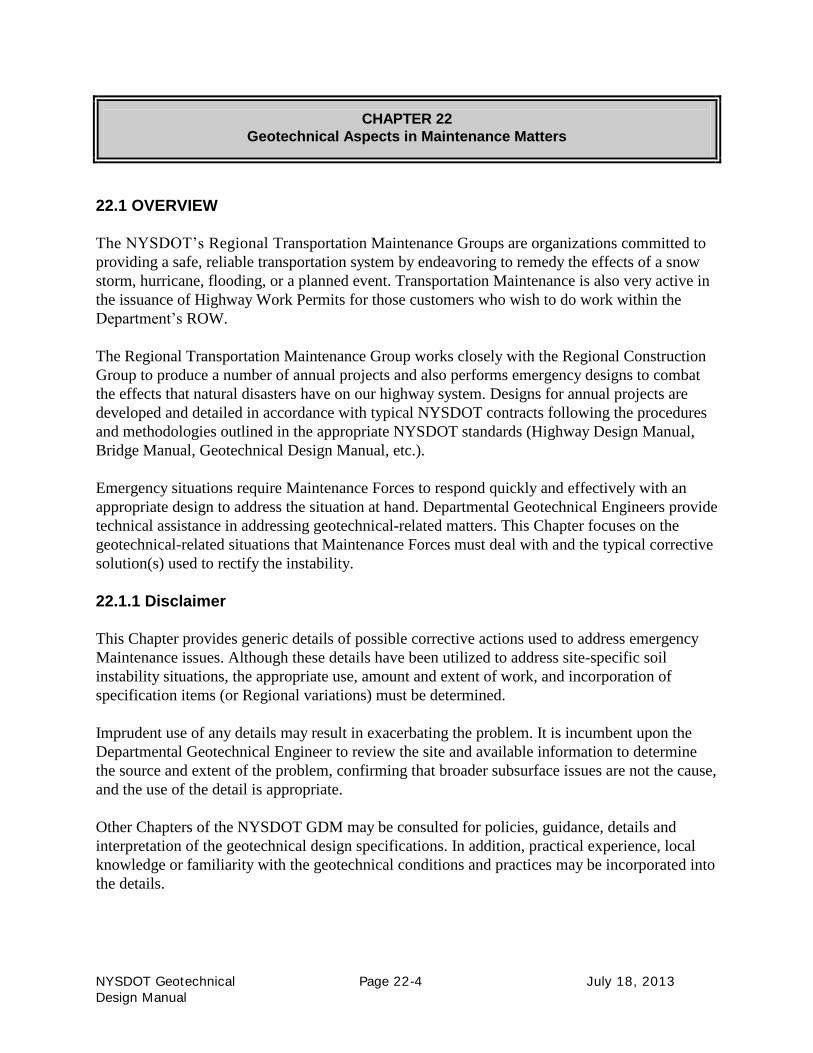
Typically, early warning signs can alert observant Maintenance employee of an unstable
slope. If an instability is identified in its early stages, actions may be taken to prevent further
movement, prevent major failure, and save the cost of an expensive repair. Some early
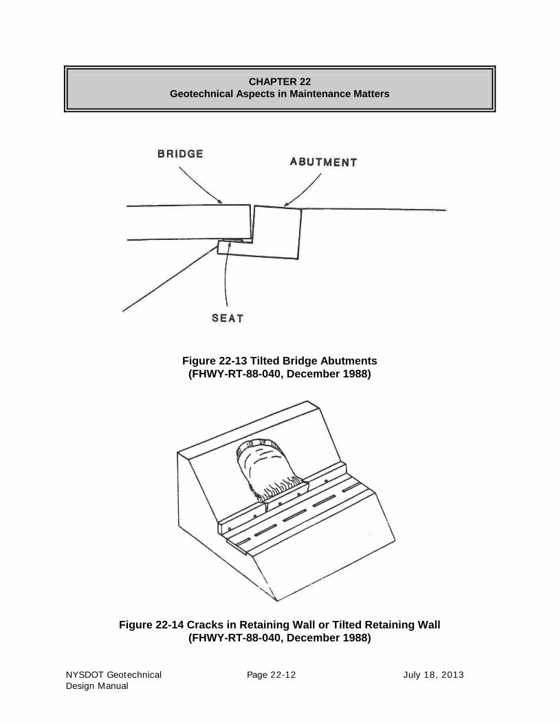
warning signs provided in FHWA-RT-88-040 are identified in Figures 22-1 through 22-14.

CHAPTER 22
Geotechnical Aspects in Maintenance Matters
NYSDOT Geotechnical Page 22-6 July 18, 2013
Design Manual
Figure 22-1 Development of Tension Cracks at the
Top of the Roadway Slope or Cut Slope
(FHWY-RT-88-040, December 1988)
Figure 22-2 Development of Escarpments in or above Roadway
(FHWY-RT-88-040, December 1988)

CHAPTER 22
Geotechnical Aspects in Maintenance Matters
NYSDOT Geotechnical Page 22-7 July 18, 2013
Design Manual
Figure 22-3 Dip in Guardrail
(FHWY-RT-88-040, December 1988)
Figure 22-4 Dip in Highway Grade
(FHWY-RT-88-040, December 1988)
CHAPTER 22
Geotechnical Aspects in Maintenance Matters
NYSDOT Geotechnical Page 22-8 July 18, 2013
Design Manual
Figure 22-5 Bulges Above, On, or Below Highway Roadway
(FHWY-RT-88-040, December 1988)
Figure 22-6 Broken Paved Ditch
(FHWY-RT-88-040, December 1988)
CHAPTER 22
Geotechnical Aspects in Maintenance Matters
NYSDOT Geotechnical Page 22-9 July 18, 2013
Design Manual
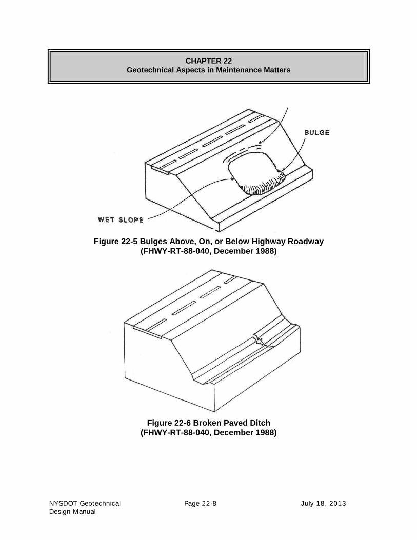
Figure 22-7 Slope Erosion Caused by Discharge from Drainage Structure
(FHWY-RT-88-040, December 1988)
Figure 22-8 Indications of the Presence of Groundwater Table
by Springs Near the Toe of Slope
(FHWY-RT-88-040, December 1988)
CHAPTER 22
Geotechnical Aspects in Maintenance Matters
NYSDOT Geotechnical Page 22-10 July 18, 2013
Design Manual
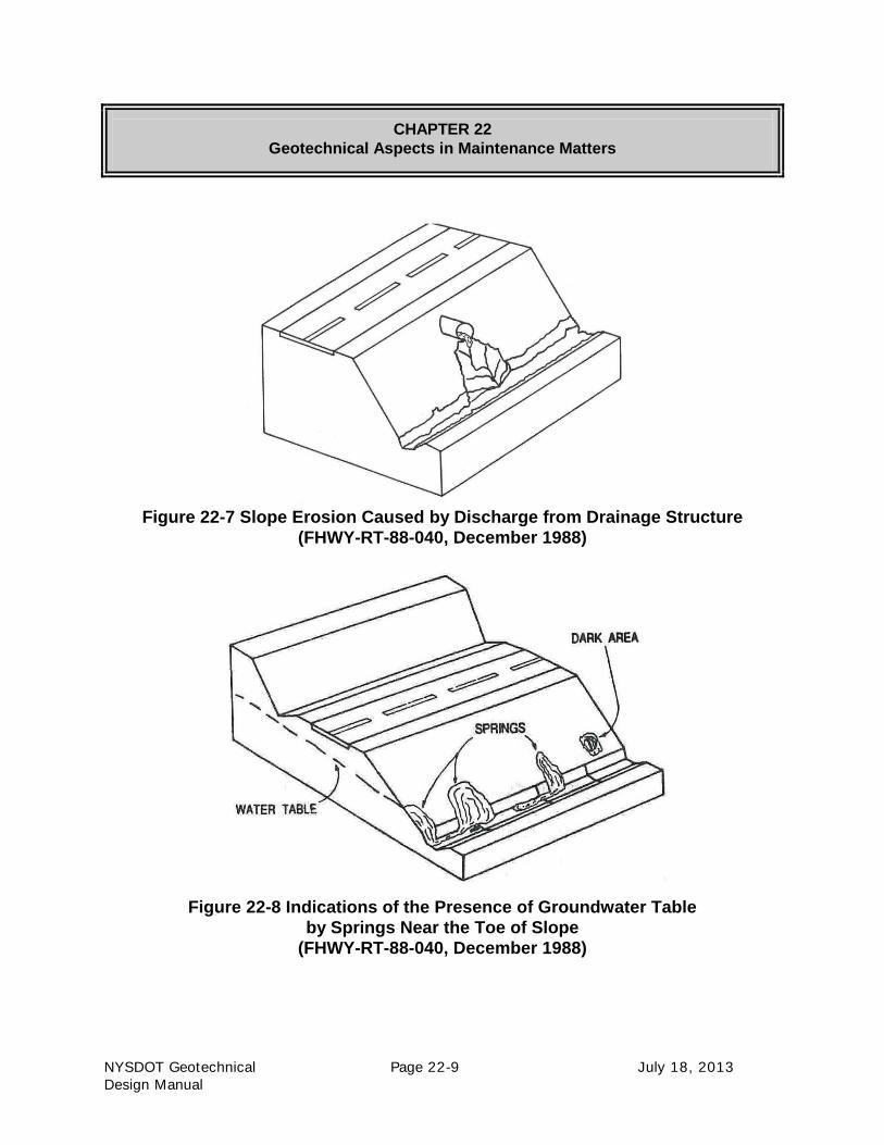
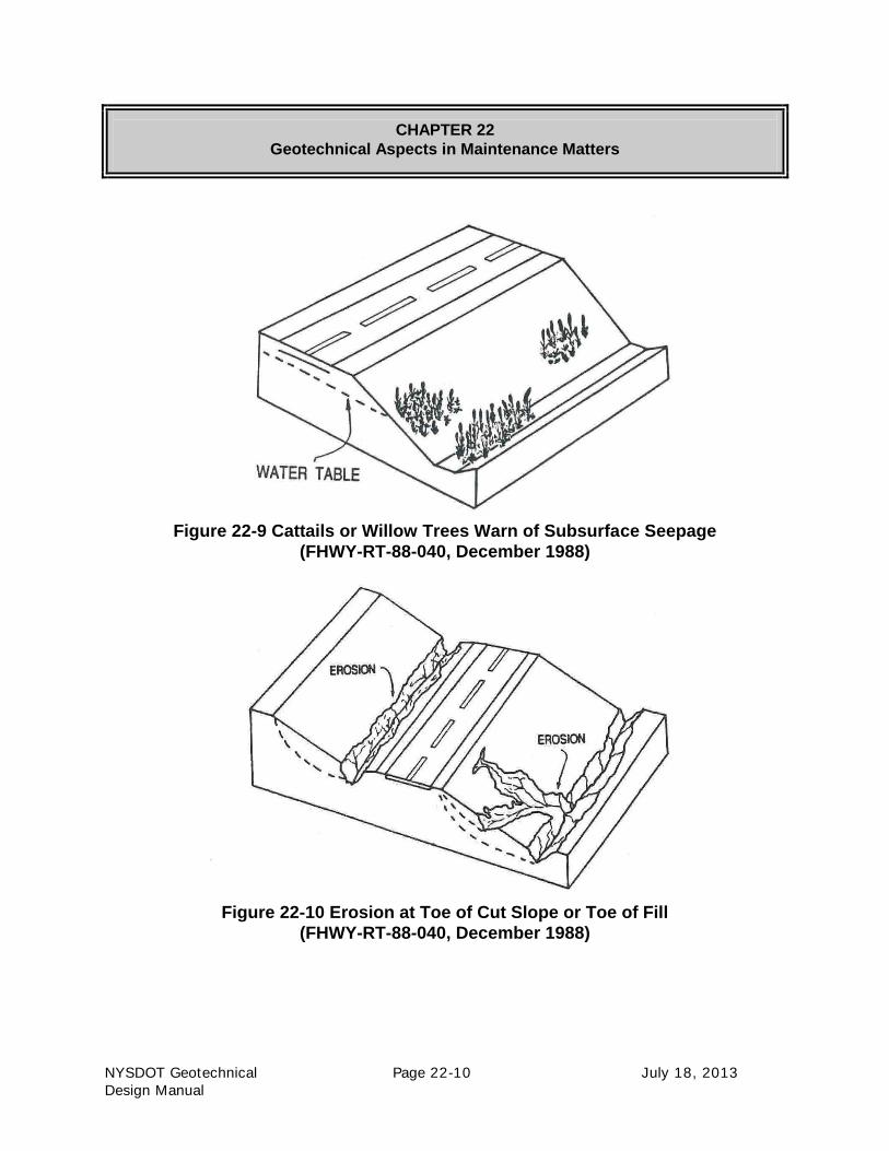
Figure 22-9 Cattails or Willow Trees Warn of Subsurface Seepage
(FHWY-RT-88-040, December 1988)
Figure 22-10 Erosion at Toe of Cut Slope or Toe of Fill
(FHWY-RT-88-040, December 1988)

CHAPTER 22
Geotechnical Aspects in Maintenance Matters
NYSDOT Geotechnical Page 22-11 July 18, 2013
Design Manual
Figure 22-11 Tilted or Curved Trees
(FHWY-RT-88-040, December 1988)
Figure 22-12 Leaning Telephone Poles
(FHWY-RT-88-040, December 1988)
CHAPTER 22
Geotechnical Aspects in Maintenance Matters
NYSDOT Geotechnical Page 22-12 July 18, 2013
Design Manual
Figure 22-13 Tilted Bridge Abutments
(FHWY-RT-88-040, December 1988)
Figure 22-14 Cracks in Retaining Wall or Tilted Retaining Wall
(FHWY-RT-88-040, December 1988)

CHAPTER 22
Geotechnical Aspects in Maintenance Matters
NYSDOT Geotechnical Page 22-13 July 18, 2013
Design Manual
22.3 THE EROSIVE ACTION OF WATER
Erosion is the wearing away of the surface of the earth by the forces of wind, water and gravity.
Erosion can cause serious problems, including sedimentation of waterways and ecological
collapse due to loss of the nutrient rich upper soil layers. Erosion is divided into two main types:
wind and water. This section focuses on the effects from water movement.
Rainfall. The impact of a falling raindrop creates a small crater in the soil, ejecting soil particles.
Once the rate of rain fall is faster than the rate of infiltration into the soil, surface runoff occurs
and carries the loosened soil particles down slope. The primary types of erosion that occur as a
direct result of rainfall are:
• Raindrop Splash: Raindrops impact the soil with tremendous energy causing the soil
particles to be dislodged or detached. In addition to the erosion, the impact of the rainfall
on bare soil can change the structure of the soil by destroying its existing open structure
and increasing the compaction. Fine particles of organic matter are separated from
heavier soil particles, reducing the infiltration capacity of the soil and increasing the
runoff potential.
• Sheet Erosion: Sheet Erosion: Sheet erosion is the removal of soil from sloping land in
thin layers or sheets. Sheet erosion removes the soil without the development of
conspicuous water channels.
• Rill Erosion: Rill erosion occurs where sheet flow becomes concentrated in numerous
small but conspicuous water channels or tiny rivulets. These miniscule, transient,
concentrated flow paths function as both sediment source and sediment delivery systems
for erosion on hill slopes.
• Gulley Erosion: Gulley erosion is the result of concentrated flow much greater than with
rills. It occurs when runoff water accumulates and then rapidly flows in concentrated,
narrow channels during or immediately after heavy rains or melting snow, removing soil
to a considerable depth.
Rivers and Streams. The movement of a high volume of water through rivers and streams has
an erosive effect on the surrounding land mass. The primary types of erosion that occur as a
direct result of water flow in rivers and streams are:
• Valley or Stream Erosion: Valley or stream erosion occurs with continued water flow
along a linear feature. The erosion is both downward (deepening the valley) and
headward (extending the valley into the hillside). There are various stages to stream
erosion:
o Earliest Stage: the erosive activity is predominantly vertical, the valleys have a
typical V-shaped cross section and the stream gradient is relatively steep.
o Secondary Stage: as some base level is reached, the erosive activity switches to
lateral erosion (i.e., bank erosion), which widens the valley floor and creates a

CHAPTER 22
Geotechnical Aspects in Maintenance Matters
NYSDOT Geotechnical Page 22-14 July 18, 2013
Design Manual
narrow floodplain. The stream gradient becomes nearly flat, and lateral deposition
of sediments becomes important as the stream meanders across the valley floor.
• Bank Erosion: Bank erosion is the wearing away of the banks of a stream or river. This is
distinguished from changes on the bed of the watercourse, which is referred to as scour.
• Toe Undercutting: Cutting away at the base, or underpart, of a hydraulic structure by the
action of water. This scouring action at the base of a stream bank removes materials by
the physical action of flowing water and the sediment that it carries. The undercutting of
the bank toe typically results in a block slide or toppling of the bank slope into the stream.
• Piping: Erosion by percolating water (formed by pressure when the hydraulic head
exceeds a certain critical value) in a layer of subsoil that results in caving and in the
formation of narrow conduits, tunnels, or "pipes" through which soluble or granular soil
material is removed. Piping can cause gulley erosion by tunnel collapse as well as
impacting the stream bank stability by weakening the overlying bank material.
Floods. At extremely high flows, vortices are formed by large, whirling volumes of rapidly
rushing water which overwhelms the environment. Vortices cause extreme local erosion and can
pluck bedrock and creating pothole-type geographical features (i.e., rock-cut basins).
Flash floods can result in loss of soil under the shoulder and pavement. The “flash” or rush of
water from an extreme event can undermine shoulders and pavement when the flow of water
exceeds the capacity of the surface drainage and the water runs along the edge of the road.
22.3.1 Sheet, Rill, and Gulley Erosion of Sideslopes
The following are some solutions to primary types of erosion that occur as a direct result of
rainfall.
1. Clean & Re-Grade Ditches: This alternate consists of cleaning and re-grading the existing
ditches at the top of the existing slope. The elimination of the built-up channelization
element concentrating flow to one particular area of the slope may eliminate further rill
and gulley erosion.

CHAPTER 22
Geotechnical Aspects in Maintenance Matters
NYSDOT Geotechnical Page 22-15 July 18, 2013
Design Manual
2. Rolled Erosion Control Product: This alternate consists of installing a rolled erosion
control product (RECP). A RECP consist of prefabricated blankets or netting which are
formed from both natural and synthetic materials. The predominantly used RECPs
generally fall into the following two categories:
• Erosion control blanket (ECB): A temporary, degradable RECP composed of
processed natural or polymer fibers mechanically, structurally or chemically bound
together to form a continuous matrix to provide erosion control.
• Turf reinforcement mat (TRM): A RECP composed of non-degradable synthetic
fibers, filaments, nets, wire mesh and/or other elements, processed into a permanent,
three-dimensional matrix. TRM’s provide erosion control and additionally provide
long-term functionality by permanently reinforcing vegetation during and after
maturation.
In situations where the erosive action is high, producing rills and gullies, a TRM is
recommended.
Figure 22-15 Rolled Erosion Control Product

CHAPTER 22
Geotechnical Aspects in Maintenance Matters
NYSDOT Geotechnical Page 22-16 July 18, 2013
Design Manual
3. Stone Lined Ditch: This alternate consists of creating a stone lined ditch section down the
slope. In situations where the erosive action is high, producing rills and gullies, the
concentration of water may be channelized into a stone lined ditch. A positive outlet at
the ditch terminus is required. A successful ditch design must satisfy two requirements:
• ditch capacity, and
• stability
Should the maximum applied tractive force that can be applied by the flowing water on
the ditch boundary exceed the forces resisting movement of the soil, erosion will occur.
The stone fill provides enough frictional resistance to overcome the applied tractive force
and remain in place.
Figure 22-16 Stone Lined Ditch

CHAPTER 22
Geotechnical Aspects in Maintenance Matters
NYSDOT Geotechnical Page 22-17 July 18, 2013
Design Manual
4. Geocells on Slope: This alternate consists of installing geocells on the slope. A geocell is
a honeycombed shaped three-dimensional soil confinement system typically backfilled
with topsoil. The vegetative soil infill performs well in these cellular confinement
systems, which provides reinforcement in the root zone and directs flows over the tops of
the cells thereby increasing the shear resistance of the fill.
Figure 22-17 Geocells on Slope

CHAPTER 22
Geotechnical Aspects in Maintenance Matters
NYSDOT Geotechnical Page 22-18 July 18, 2013
Design Manual
4. Geofiber Reinforced Fill: This alternate consists of installing a geofiber reinforced fill in
eroded areas of an existing oversteepened reinforced slope. Geosynthetic fibers are
expandable polypropylene strands used to stabilize soils. In situations where water has
been channelized and inadvertently directed over an oversteepened slope causing erosion,
the corrective measure must not only address the replacement of material but also
consider long-term stability. The inclusion of discrete fibers in select granular fill
increases both the apparent cohesion and the angle of internal friction of the replacement
soil.
Figure 22-18 Geofiber Reinforced Fill

CHAPTER 22
Geotechnical Aspects in Maintenance Matters
NYSDOT Geotechnical Page 22-19 July 18, 2013
Design Manual
22.3.2 Groundwater Seepage Affecting Sideslopes
Seepage is the slow movement of water through small openings and spaces in the surface of
unsaturated soil into or out of a body of surface or subsurface water.
A site review should be performed to determine the cause(s) of the sloughing slope. Some items
to analyze include, first and foremost, the stability of the sloughed slope and its vicinity to any
adjacent structure, and the potential for the shallow surface slough to be part of a deep-seated
failure. Once stability is assessed, determine the cause of the sloughed slope to provide a
corrective solution. The path of surface water flow and its potential contribution to the problem
should be analyzed. Clogged catch basins combined with sheet flow directed and channeled
towards a slope can produce major problems with even the flattest of slopes.
The following are some solutions to shallow sloughs.
1. Clean & Re-Grade Ditches: This alternate consists of cleaning and re-grading the existing
ditches. Elimination of ponding water and re-establishing channelled flow to a positive
outlet may dry up the area of concern.
2. Stone Blanket: This alternate consists of excavating the sloughed material and installing
stone fill. The stone fill is highly permeable while also providing enough frictional
resistance to overcome seepage forces and remain in place. Typically, geotextile slope
protection is placed along the slope prior to the installation of the stone fill to provide a
filter layer to prevent migration of the native soil into the drainage blanket.
Figure 22-19 Stone Slope Blanket with Geotextile Filter

CHAPTER 22
Geotechnical Aspects in Maintenance Matters
NYSDOT Geotechnical Page 22-20 July 18, 2013
Design Manual
An alternate to a geotextile filter is a filter layer consisting of crushed stone as shown in Figure
22-20.
Figure 22-20 Stone Slope Blanket with Stone Filter Layer
In situations where aesthetics are a concern regarding the amount and overall look of stone fill on
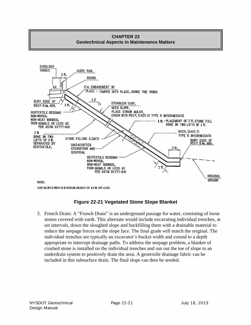
a slope, an alternate to consider is a vegetated stone slope as shown in Figure 22-21. This
alternate allows the placement of the stone to provide the necessary drainage while allowing the
establishment of turf on blend in with the surrounding area.
CHAPTER 22
Geotechnical Aspects in Maintenance Matters
NYSDOT Geotechnical Page 22-21 July 18, 2013
Design Manual
Figure 22-21 Vegetated Stone Slope Blanket
3. French Drain: A “French Drain” is an underground passage for water, consisting of loose
stones covered with earth. This alternate would include excavating individual trenches, at
set intervals, down the sloughed slope and backfilling them with a drainable material to
reduce the seepage forces on the slope face. The final grade will match the original. The
individual trenches are typically an excavator’s bucket width and extend to a depth
appropriate to intercept drainage paths. To address the seepage problem, a blanket of
crushed stone is installed on the individual trenches and run out the toe of slope to an
underdrain system to positively drain the area. A geotextile drainage fabric can be
included in this subsurface drain. The final slope can then be seeded.

CHAPTER 22
Geotechnical Aspects in Maintenance Matters
NYSDOT Geotechnical Page 22-22 July 18, 2013
Design Manual
Figure 22-22 French Drains

CHAPTER 22
Geotechnical Aspects in Maintenance Matters
NYSDOT Geotechnical Page 22-23 July 18, 2013
Design Manual
4. GRSS with Chimney Drain: In situations where a widening is required, this alternate
consists of excavating the sloughed material and installing crushed stone to act as a
subsurface chimney drain. The widening may be accomplished with normal fill material,
or depending on restrictions, may be installed utilizing GRSS. The chimney drain allows
for a positive outlet of the groundwater which will not resurface and continue to be a
maintenance problem at a later date.
Figure 22-23 GRSS with Chimney Drain
CHAPTER 22
Geotechnical Aspects in Maintenance Matters
NYSDOT Geotechnical Page 22-24 July 18, 2013
Design Manual
22.3.3 Groundwater Conflicts Affecting Pavements
A spring discharge is the situation where water flows to the surface from underground (i.e. a site
where the aquifer surface meets the ground surface). Springs or high groundwater elevation can
adversely affect the pavement section.
A site review should be performed to determine the extent of the detrimental condition. Some
items to analyze include topography, existing rideability, adjacent watercourses, surrounding
vegetation, and ditch sections. The results of the site review will provide the extent of the
condition along with the severity, which may be used to provide a corrective solution.
The following are some solutions to groundwater conflicts affecting pavement sections.
1. Weeps: This alternate consists of excavating and installing weeps. Weeps, or weeping
tile, derives its practice from tile drainage in agriculture where too much subsurface water
can be counterproductive by preventing root development and inhibiting the growth of
crops. By adding drain tile, the water table is effectively lowered.

CHAPTER 22
Geotechnical Aspects in Maintenance Matters
NYSDOT Geotechnical Page 22-25 July 18, 2013
Design Manual
Figure 22-24 Drainage Weeps

CHAPTER 22
Geotechnical Aspects in Maintenance Matters
NYSDOT Geotechnical Page 22-26 July 18, 2013
Design Manual
2. Select Granular Subgrade: This alternate consists of undercutting the pavement section
and replacing the subgrade material. If the existing subgrade material contains a sufficient
amount of fines which, combined with the groundwater conflict, causes instability (and
there is no time to effectively drain the area), an undercut may be warranted. Although
this alternate replaces the material in the subgrade area, the source of the problem
(groundwater) still needs to be addressed. A positive outlet for the elevated groundwater
is necessary.
Figure 22-25 Select Granular Subgrade
3. Geosynthetic Reinforcement in Pavement Section: This alternate consists of
strengthening the pavement section to reduce the amount of undercut (as discussed in
Alternate #2). To strengthen the pavement section, a biaxial geogrid is utilized. The
pavement section gains strength from the structural enhancement contribution of the
biaxial geogrids. Although this alternate adds strength to the pavement section, as with
Alternate #2, the source of the problem (groundwater) still needs to be addressed. A
positive outlet for the elevated groundwater is necessary.

CHAPTER 22
Geotechnical Aspects in Maintenance Matters
NYSDOT Geotechnical Page 22-27 July 18, 2013
Design Manual
Figure 22-26 Geosynthetic Reinforcement in Pavement Section

CHAPTER 22
Geotechnical Aspects in Maintenance Matters
NYSDOT Geotechnical Page 22-28 July 18, 2013
Design Manual
22.3.4 Stream or Overland Flow Scouring
Scouring is an erosion process resulting from the action of the flow of air, ice, or water. A scour
hole or depression is a hollowed area in the stream channel caused by water that scours below the
grade of the stream.
The following are some solutions to scouring along the stream channel causing slope instability.
1. Stone Blanket: This alternate consists of stabilizing the slope with stone fill. The stone
fill provides enough frictional resistance to overcome the scouring forces and remain in
place. Two details are provided. They identify basic stone layout dimensions based on
Geotechnical Design Procedure (GDP-10) Bank and Channel Protective Lining Design
Procedures with Stone Filling (Heavy) as a default if hydraulic information in not
available. The details were created to address storm-related occurrences. The stone filling
is placed a minimum 3 ft. above observed flood level (debris in trees, mud lines, etc). The
slope is to be re-constructed such that 5 ft. of width will be provided between the top of
slope and edge of shoulder for guiderail deflection.
The differences between the two details are as follows:
• Repair No. 1 – utilizes a 50/50 mix of Size #1 & #2 (See Table 703-4 Sizes of
Stone, Gravel, and Slag of the NYSDOT Standard Specifications) crushed stone
or gravel behind (heavy or medium) stone fill. A geotextile bedding item is placed
between crushed material and stone filling.
• Repair No. 2 – utilizes light stone fill behind (heavy or medium) stone fill. A
geotextile bedding item is placed between stone filling and overlying embankment
material.
It is important to note that guiderail in not shown. The guiderail type and layout redesign
must be addressed.

CHAPTER 22
Geotechnical Aspects in Maintenance Matters
NYSDOT Geotechnical Page 22-29 July 18, 2013
Design Manual
Figure 22-27 Stone Blanket – Repair No. 1

CHAPTER 22
Geotechnical Aspects in Maintenance Matters
NYSDOT Geotechnical Page 22-30 July 18, 2013
Design Manual
Figure 22-28 Stone Blanket – Repair No. 2

CHAPTER 22
Geotechnical Aspects in Maintenance Matters
NYSDOT Geotechnical Page 22-31 July 18, 2013
Design Manual
2. Sta-Pods™: This alternate consists of excavating or re-grading the scoured material and
installing a series of Sta-Pods™. Sta-Pods™ are an interlocking concrete armor system.
Their massive form and interlocking design provide sufficient resistance to overcome
scouring forces and remain in place. In addition, their high strength, air-entrained
concrete protects against deterioration associated with freeze-thaw cycles and exposure to
salt water.
Figure 22-29 Sta-Pods
CHAPTER 22
Geotechnical Aspects in Maintenance Matters
NYSDOT Geotechnical Page 22-32 July 18, 2013
Design Manual
The following are some solutions to scour holes developing at the outlet of culverts.
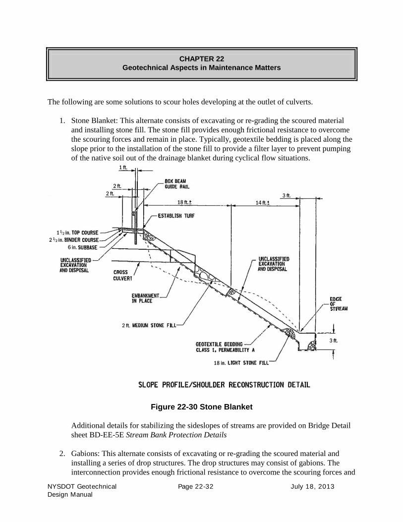
1. Stone Blanket: This alternate consists of excavating or re-grading the scoured material
and installing stone fill. The stone fill provides enough frictional resistance to overcome
the scouring forces and remain in place. Typically, geotextile bedding is placed along the
slope prior to the installation of the stone fill to provide a filter layer to prevent pumping
of the native soil out of the drainage blanket during cyclical flow situations.
Figure 22-30 Stone Blanket
Additional details for stabilizing the sideslopes of streams are provided on Bridge Detail
sheet BD-EE-5E Stream Bank Protection Details
2. Gabions: This alternate consists of excavating or re-grading the scoured material and
installing a series of drop structures. The drop structures may consist of gabions. The
interconnection provides enough frictional resistance to overcome the scouring forces and

CHAPTER 22
Geotechnical Aspects in Maintenance Matters
NYSDOT Geotechnical Page 22-33 July 18, 2013
Design Manual
remain in place. The drop structure itself provides an energy dissipation effect and allows
flow to meet the existing channel without disturbance.
Figure 22-31 Gabions
CHAPTER 22
Geotechnical Aspects in Maintenance Matters
NYSDOT Geotechnical Page 22-34 July 18, 2013
Design Manual
22.4 DETERIORATION OF HIGHWAY SLOPES
As identified in FHWA-RT-88-040, the deterioration of a highway slope based on costs may
be assigned to one of the following categories:
• Routine Maintenance: This category contains slope problems which are only minor (e.g.
small removal of rock or soil debris from roadway, roadway settled or sagged requiring
patching for the first time).
• Extraordinary Maintenance: This category contains slope problems which have reached a
stage where it continues to reoccur and extraordinary costs and measures are incurred to
halt or delay the slope movement and maintain traffic flow (e.g. more than one patching
has been performed, pavement cracks have been sealed on several occasions and guiderail
has been re-set).
• Slide Restoration: This category contains slope problems which have reached a condition
where routine and extraordinary maintenance costs approach or represent a sizeable
portion of the costs of restoring the highway section to NYSDOT standards.
Maintenance Forces regularly perform routine maintenance in their role of controlling the natural
deterioration of a highway facility. When Extraordinary Maintenance or Slide Restoration
situations are identified, Resident Engineers rely on Departmental Geotechnical Engineers to
provide technical assistance in addressing slope stability.
22.4.1 Shoulder Back-up Fixes
The following are some solutions to re-occurring shoulder ravelling/guiderail tipping due to
oversteepened backup slopes.
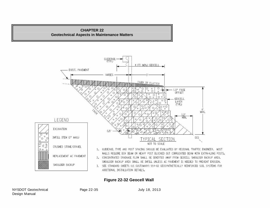
1. Geocells: This alternate consists of installing a small geocell system to support the
required guiderail offset. To install this system, the shoulder would be excavated and the
geocells installed.
The following figure provides details of a geocell wall. The height of the wall will depend
on the grade of the existing slope.
CHAPTER 22
Geotechnical Aspects in Maintenance Matters
NYSDOT Geotechnical Page 22-35 July 18, 2013
Design Manual
Figure 22-32 Geocell Wall

CHAPTER 22
Geotechnical Aspects in Maintenance Matters
NYSDOT Geotechnical Page 22-36 July 18, 2013
Design Manual
2. GRSS: This alternate consists of installing a small timber faced GRSS system to support
the required guiderail offset. To install this system, the shoulder would be excavated and
the GRSS & timber facing installed. Depending on the location, additional protection
may be warranted – the example provided below includes the installation of dry rip rap
due to the vicinity of a stream.
Figure 22-33 Timber Faced GRSS

CHAPTER 22
Geotechnical Aspects in Maintenance Matters
NYSDOT Geotechnical Page 22-37 July 18, 2013
Design Manual
3. Stone Blanket: This alternate consists of installing an oversteepened stone blanket to
support the required guiderail offset. To install this system, the shoulder would be
excavated, regraded, and compacted and the stone fill installed.
Figure 22-34 Stone Slope Blanket

CHAPTER 22
Geotechnical Aspects in Maintenance Matters
NYSDOT Geotechnical Page 22-38 July 18, 2013
Design Manual
22.4.2 Rockfalls
The Transportation Maintenance Division has implemented a policy of reporting rockfalls along
NYSDOT right-of-way. These rockfall incidents are documented on the Rockfall Report Form
(see Figure 22-35), which was developed in conjunction with the Geotechnical Engineering
Bureau. A copy of the completed form is transmitted to the Geotechnical Engineering Bureau to
provide a timely response for the site stability assessment and to gather historical data.
Instructions for processing incoming rockfall report forms have been distributed to the
Maintenance Residencies and are provided in Figure 22-36.
22.4.2.1 Rockfall Database – The Rock Slope Inventory
The Geotechnical Engineering Bureau’s Engineering Geology Section obtains, inputs, and
updates data in a database file, including site description, geological rating, contract work
history, and maintenance work history. Rockfall reports from the Regions are incorporated into
the database to supplement the data of each rock slope site.
• New Slope: The Regions may add new slopes to the program at any time by notifying the
Geotechnical Engineering Bureau. Adding a slope will prompt Geologists of the
Engineering Geology Section to perform a rating.
• Slopes in the Database: Any remedial work to slopes already in the program, by
construction contract, maintenance contract, or maintenance forces, is to be recorded by
the Region and reported upon completion to the Geotechnical Engineering Bureau
through the Regional Geotechnical Engineer, triggering the re-evaluation process.
Rock slopes are rated as described in Geotechnical Engineering Manual (GEM-15) Rock Slope
Rating Procedure, which outlines the creation of "factors" -- geologic, section, and human
exposure -- for computing relative risk of a rockfall-related accident occurring at any site listed in
the statewide rock slope inventory

CHAPTER 22
Geotechnical Aspects in Maintenance Matters
NYSDOT Geotechnical Page 22-39 July 18, 2013
Design Manual
Figure 22-35 Rockfall Report

CHAPTER 22
Geotechnical Aspects in Maintenance Matters
NYSDOT Geotechnical Page 22-40 July 18, 2013
Design Manual
ITEMS
1. "Reference Marker Information," requires the identification numbers from the closest
reference marker.
Line 1 _______ EXAMPLE: ___9W__
Line 2 _______ __8302_
Line 3 _______ __ 1085_ _
2. Enter the posted route number(s).
3. Enter the town or village where the rockfall occurred.
4. Enter the county where the rockfall occurred.
5. Enter the residency of jurisdiction where the rockfall occurred.
6. Enter the name of the person who first reported the rockfall, if known.
7. Enter the side of the road the rockfall occurred (based on ascending RM direction)
8. Enter the date of the rockfall, if known.
9. Enter the approximate time of rockfall, if known.
10. Circle any appropriate weather conditions. Note unusual conditions under 'other', if
necessary.
11. Enter the estimated total volume of the fallen blocks of rock (use cubic yards).
12. Circle all locations where fallen blocks of rock were found.
13. Circle the approximate size of the largest fallen block of rock.
Items 14, 15 and 16 pertain to accident information, if any, related to the rockfall. Check the
appropriate space for each item.
17. Use this space for additional comments. Items which should be noted here include, but are
not limited to, the following: Possibility that additional material may fall, scaling possibly
required for cleanup, etc.
Items 18 and 19 pertain to contact people at the Residency.
18. Enter the name and phone number of the Residency contact person who will be available to
answer questions regarding the rockfall.
19. Enter your name and the date you completed the form.
20. Distribute copies of this completed form as indicated. Call or notify the Regional
Geotechnical Engineer or the Geotechnical Engineering Bureau (GEB) if a condition exists
requiring immediate evaluation by an Engineering Geologist.
Figure 22-36 Instructions for Completing the Rockfall Report Form

CHAPTER 22
Geotechnical Aspects in Maintenance Matters
NYSDOT Geotechnical Page 22-41 July 18, 2013
Design Manual
22.4.3 Problem Soil Slopes
Resident Engineers of the Transportation Maintenance Division rely on Departmental
Geotechnical Engineers to provide technical assistance in addressing slope stability in situations
when Extraordinary Maintenance or Slide Restoration situations are identified.
As shown in NYSDOT GDM Section 22.2 Understanding the Signs of Movement, slope
instability may be identified via early warning signs. These early warning signs are typically
addressed by Routine Maintenance (e.g. patching, sealing, paving). Once the situation
extends beyond Routine Maintenance, the Resident Engineer will consult with the Regional
Geotechnical Engineer for investigative techniques and development of preliminary
corrective measures and costs.
These sites are considered problem areas due to:
• The physical situation it exhibits on the highway section and its impression on the
traveling public regarding rideability, and
• The administrative situation it instigates regarding the management of equipment,
crews, and finances:
o Corrective measures for slope instability can be above and beyond the resources of
Maintenance Forces, and
o Costs for the corrective measures for slope instability can be overshadowed by
administrative costs in a stand-alone NYSDOT contract as these sites are typically
isolated areas of minor extent. Most situations do not warrant excusing the
lopsided cost-benefit analysis to address the site.
22.4.3.1 The Earth Slope Inventory
All the information regarding the investigation, analysis, and development of preliminary
corrective measures and costs for the site is managed by the Regional Geotechnical
Engineer. They keep an informal Earth Slope Inventory which lists various problem slopes
within their Region. The inventory provides a resource in addressing slopes by mapping and
coordinating locations to aid in initiating a NYSDOT contract for multiple areas.
By effectively managing problem slopes, the Regional Geotechnical Engineer can be a
valuable resource to the Resident Engineer by eliminating the need for continual
maintenance operations to correct the roadway deficiency, extending the useful life of the
highway and allowing it to be maintained in a structurally sound condition using cost-
effective geotechnical treatments that provide low life cycle costs, as well as minimizing
environmental impacts.

CHAPTER 22
Geotechnical Aspects in Maintenance Matters
NYSDOT Geotechnical Page 22-42 July 18, 2013
Design Manual
22.4.4 Sink Holes
Due to the inherent presence of water, a forced seepage situation can occur around culverts
and closed drainage structures in instances where joints, discontinuities or corroded
openings disperse water into the subgrade. The forced seepage action in such circumstances
can result in large and extensive voids beneath the travel way. When the voids expand to
such an extent that the subgrade’s natural arching effects cannot overcome the imposed
roadway loading, the isolated area of the subgrade fails. This failure produces a sink hole in
the pavement section.
Sink holes can also occur naturally where limestone, and gypsum (more common in New
York State) exist. Limestone created by ancient seas was deposited in layers with slight
differences in chemical compositions, hardness and thickness. Slightly acidic water can
slowly dissolve weak layers. The chemical erosion eventually causes voids into which
overlying sediments can collapse.
Resident Engineers of the Transportation Maintenance Division rely on Departmental
Geotechnical Engineers to provide technical assistance in addressing sink holes in situations
when Extraordinary Maintenance situations are identified. Once the situation extends beyond
Routine Maintenance, the Resident Engineer will consult with the Regional Geotechnical
Engineer for investigative techniques and development of preliminary corrective measures
and costs.
22.4.4.1 Grouting
Repair of voids:
• Sink holes: Permeation grouting is a technique used to remedy the presence of voids
beneath the pavement. Permeation grouting is a general term for grouting that is carried
out to fill pervasive void space. Grouting may be performed to either improve the soil
structure by addressing a specific void or stabilize entire areas by reducing the hydraulic
conductivity of the soil or rock through voluminous intrusion of grout quantities.
Permeation grouting is typically injected utilizing sleeve ports laid-out in a grid pattern.
This method allows the grout to be injected at a specified location and elevations
depending on the subsurface conditions and grout properties.
• Culverts: Permeation grouting is a technique used to remedy the presence of voids
beneath or surrounding a culvert, or within the annular space between an existing culvert
and a new pipe liner.
All grouting is typically accomplished with the stream diverted from the culvert utilizing
a cofferdam/temporary water diversion structure.

CHAPTER 22
Geotechnical Aspects in Maintenance Matters
NYSDOT Geotechnical Page 22-43 July 18, 2013
Design Manual
The culvert invert (if necessary) is sealed with ready mix grout using a grout pump to
address any voids in the invert as well as to construct a smooth, straight invert to facilitate
pipe slip-lining.
Access holes are drilled through the existing culvert at intervals alternating at the 10 & 2
o’clock and 4 & 8 o’clock positions to a desired depth. Grouting commences at the
downstream end of the culvert using an on-site mixer with the mix ratios and mix
sequence as designed. If large voids are encountered during soil grouting, they are filled
with ready-mix grout. Sink holes will also be grouted from the surface during the soil
grouting operation.
Annular grouting begins after soil grouting has been completed and the new slip-lining
has been installed and blocked against movements due to anticipated grout pressures.
Grouting the annular space begins at the downstream end of the culvert and is performed
through ports that have been welded into the new pipe. The ends of the culvert are
typically addressed by installing wooden bulkheads to contain the annular space grout.
22.5 REFERENCES
Fox, G.A., Chu-Agor, M.L., Wilson, G.V., Seepage Erosion: A Significant Mechanism of Stream
Bank Failure, Proceedings of the American Society of Civil Engineers (ASCE), World
Environmental Water and Resources Congress, May, 2007.
Geotechnical Engineering Bureau, Bank and Channel Protective Lining Design Procedures,
Geotechnical Design Procedure GDP-10, New York State Department of Transportation, Office
of Technical Services, https://www.dot.ny.gov/divisions/engineering/technical-
services/technical-services-repository/GDP-10b.pdf
Geotechnical Engineering Bureau, Rock Slope Rating Procedure, Geotechnical Engineering
Manual GEM-15, New York State Department of Transportation, Office of Technical Services,
https://www.dot.ny.gov/divisions/engineering/technical-services/technical-services-
repository/GEM-15b.pdf
Hopkins, T.C., Allen, D.L., Deen, R.C., Grayson, C.G., Highway Slope Maintenance and Slide
Restoration Workshop – Participant Manual, US Department of Transportation, Federal
Highway Administration, Report No. FHWA- RT-88-040, December 1988.
Natural Resources Conservation Service (NRCS), Erosion, United States Department of
Agriculture, Colorado NRCS Home,
http://www.co.nrcs.usda.gov/technical/nri/documents/erosion.html
Roberts, B.C., Best Management Practices for Erosion and Sediment Control, United States
Department of Transportation, Federal Highway Administration, Eastern Federal Lands Highway
Division, Publication No. FHWA-FLP-94-005, June, 1995.