CHAPTER 2 LITERATURE SURVEY -...
28
9 CHAPTER 2 LITERATURE SURVEY 2.1 INTRODUCTION Induction motors account for approximately 50% of the overall electricity use in industrialized countries. In the agricultural and commercial sectors also, power consumption by ac motors is quite substantial. On an average, the energy consumed by a motor during its life cycle is 60-100 times the initial cost of the motor. Therefore efficiency of the motor is of paramount importance both during selection and operation. High electrical conductivity of copper in the rotor structure of a squirrel cage induction motor can achieve a reduction in overall energy losses of around 11%- 19% and a consequent increase in energy efficiency. This chapter reviews the comparison of various rotor construction techniques, implementation of Die-cast Copper Rotor Motor, Efficiency improvement, Energy saving potential, adoption of DCR Technology in India and the comparisons of various efficiency standards. The needs and tasks regarding the technology are also discussed. 2.2 LOSSES IN AN INDUCTION MOTOR The electric motor has a long history of development since its invention by Nicola Tesla in 1888, with earlier effort aimed at improving power and torque at reduced cost. The need for higher efficiency became apparent during the late 1970’s and by the early 1980’s. At last, one British manufacturer started to market a premium range of motors with improved efficiency. Now the trend is towards the design and manufacturing of motors with a small improved efficiency at a small extra cost (Chiricozzi et al 1997).
Transcript of CHAPTER 2 LITERATURE SURVEY -...
9
CHAPTER 2
LITERATURE SURVEY
2.1 INTRODUCTION
Induction motors account for approximately 50% of the overall electricity use in industrialized countries. In the agricultural and commercial sectors also, power consumption by ac motors is quite substantial. On an average, the energy consumed by a motor during its life cycle is 60-100 times the initial cost of the motor. Therefore efficiency of the motor is of paramount importance both during selection and operation. High electrical conductivity of copper in the rotor structure of a squirrel cage induction motor can achieve a reduction in overall energy losses of around 11%- 19% and a consequent increase in energy efficiency. This chapter reviews the comparison of various rotor construction techniques, implementation of Die-cast Copper Rotor Motor, Efficiency improvement, Energy saving potential, adoption of DCR Technology in India and the comparisons of various efficiency standards. The needs and tasks regarding the technology are also discussed.
2.2 LOSSES IN AN INDUCTION MOTOR
The electric motor has a long history of development since its invention by Nicola Tesla in 1888, with earlier effort aimed at improving power and torque at reduced cost. The need for higher efficiency became apparent during the late 1970’s and by the early 1980’s. At last, one British manufacturer started to market a premium range of motors with improved efficiency. Now the trend is towards the design and manufacturing of motors with a small improved efficiency at a small extra cost (Chiricozzi et al 1997).
10
It is needless to state that, this extra cost could be realized in the savings in the operating cost.
Since, efficiency being the ratio of the amount of work produced i.e., output power to the amount of energy consumed i.e. input power, the Induction motor losses are the difference between input and output powers, and can be classified into five categories (Boglietti et al 2003).
1. Iron losses: magnetic losses in the core laminations, hysteresis, and eddy current losses, labeled as Pc.
2. Stator I²R resistance losses: current losses in the stator windings, Ps
3. Rotor I²R resistance losses: current losses in the rotor bars and end rings, Pr.
4. Windage and friction losses: mechanical drag in bearings and cooling fans, Pw.
5. Stray load losses: mainly iron and joule losses, also called additional load losses, increasing with load and result from a multitude of sources, such as surface and slot conditions, leakage flux, etc. They are normally difficult to measure and calculate, Pl.
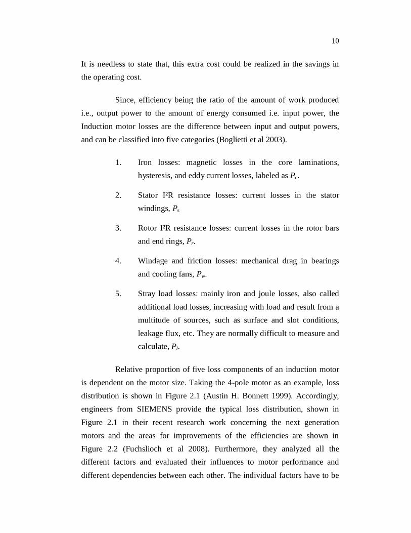
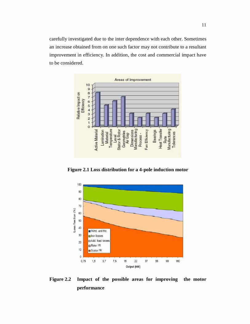
Relative proportion of five loss components of an induction motor is dependent on the motor size. Taking the 4-pole motor as an example, loss distribution is shown in Figure 2.1 (Austin H. Bonnett 1999). Accordingly, engineers from SIEMENS provide the typical loss distribution, shown in Figure 2.1 in their recent research work concerning the next generation motors and the areas for improvements of the efficiencies are shown in Figure 2.2 (Fuchslioch et al 2008). Furthermore, they analyzed all the different factors and evaluated their influences to motor performance and different dependencies between each other. The individual factors have to be
11
carefully investigated due to the inter dependence with each other. Sometimes an increase obtained from on one such factor may not contribute to a resultant improvement in efficiency. In addition, the cost and commercial impact have to be considered.
Figure 2.1 Loss distribution for a 4-pole induction motor
Figure 2.2 Impact of the possible areas for improving the motor
performance
12
For improving the efficiency of an induction motor, various
attempts are made to reduce the Watt losses in the motors and this study has
been taken up primarily to reduce rotor copper loss using DCR technology.
2.3 ROTOR CONSTRUCTIONAL METHODS
2.3.1 Induction Motors with CFR
In the early days, ‘copper bars’ were used as rotor conductors
which were inserted into rotor slots and brazed to the copper end rings to form
the squirrel cage rotor. Such fabricated copper rotor construction is dating
back to the 1920’s (Finley et al 2001).
The fabricated copper bar rotor is constructed utilizing the
following steps:
1. Stack rotor punchings on a stacking mandrel.
2. Hold punchings together along with end heads. Clamp
assembly together
3. Insert shaft into hot core, lock core in place without welding.
4. Insert bars.
5. Machine end of bars.
6. Braze end connectors to bars.
7. Turn and balance rotor assembly.
Some of the conditions to be satisfied to assure that the highest
quality and reliability is obtained when manufacturing CFR are:
Consistent clamp pressure applied uniformly to laminations
will minimize the thermal sensitivity of the rotor assembly.
13
While the clamp pressure should be consistent, it should not
be excessive. Excessive clamp pressure increases the core
losses.
The end connectors should be induction brazed to the bars.
In addition, the temperatures of both the end connectors and
bars should be continually monitored throughout the brazing
process. Induction brazing, results in much more consistent
temperature distribution than with flame brazing.
Additionally, it heats the end connector, which in turn heats
the bars. This will minimize the amount of heat that the rotor
core will have to absorb. Both of these mechanisms will
minimize the amount of residual stresses present in the end
connectors, bars, or braze joint. In addition, the rotor will
exhibit less thermal sensitivity than a flame-brazed rotor.
A loose rotor bar is the number one cause of CFR failure.
Because during starting period, the rotor bars oscillate at
Rotor Bar Vibration Frequency = 2 X % Slip X Line Freq.
The rotor bars vibrate as a consequence of high current forces
(Bredthauer et al 1994).
End heads must be designed in such a way that they exert
constant clamping force. Even if the lamination clamping
portion of the end head is axially displaced, it will exert a
constant clamping force on the rotor punchings. The rotor
will grow thermally, if the end heads are overly rigid and
they will exert too much clamping force, resulting in
increased core losses.
14
Unless it is a stress relieved, welding directly on the shaft
should be avoided. Any welding will result in residual
stresses and potential thermal instability.
Due to the above said constraints, the consistency in performance
of CFR is always questionable and also fabricating. This type of rotor
involves intensive hand labour and therefore it is expensive.
2.3.2 Induction Motors with DAR
As squirrel cage motors started dominating the Industrial scene,
Research and Development got on to eliminate or minimize the rotor
problems of the brazed construction. Then, as a technology improvement and
enabling mass and defect free production at lower cost, the die cast
Aluminium rotors got developed totally eliminating bars insertion, end rings
brazing and so on. This successful development was readily adopted all over
and today it dominates the entire world of LT squirrel cage induction motors.
The aluminium rotor is constructed utilizing the following steps:
1. Stack rotor punchings on a stacking mandrel.
2. Insert punching / mandrel stack in end connector mold.
3. Die cast (i.e., inject aluminium) rotor.
4. Insert shaft into hot rotor core.
5. Turn and balance rotor assembly.
The basic process has been unchanged since its inception.
Till 1970, Squirrel cage induction motors up to 250 HP were designed with
Aluminum Die-cast rotor having laminated steel as the core material. After
1970, as the cost of electricity went up, it became more expensive to use less
efficient motors (Hartung 1994 and Lie et al 1995). It has been illustrated
15
that significant improvement in motor efficiency can be achieved by
substituting Aluminum with Copper (Paris et al 2003).
2.3.3 Induction Motors with DCR
The resistivities of copper and aluminium for circular mil, per foot
at 20oC are 10.37 and 16.06 respectively. Hence, for the same current
requirement, the substitution of copper for aluminium results in (16.06 –
10.37)/ 16.06 = 35.4% reduction in resistance loss (John S. Hsu et al., 2000).
The overall efficiency of the machine gets increased by replacing the
aluminium material in the rotor with copper. This idea leads to
implementation of DCR technology. A DCR construction does not differ
significantly from DAR construction. The DCR imposed manufacturing
challenges that have been only recently met.
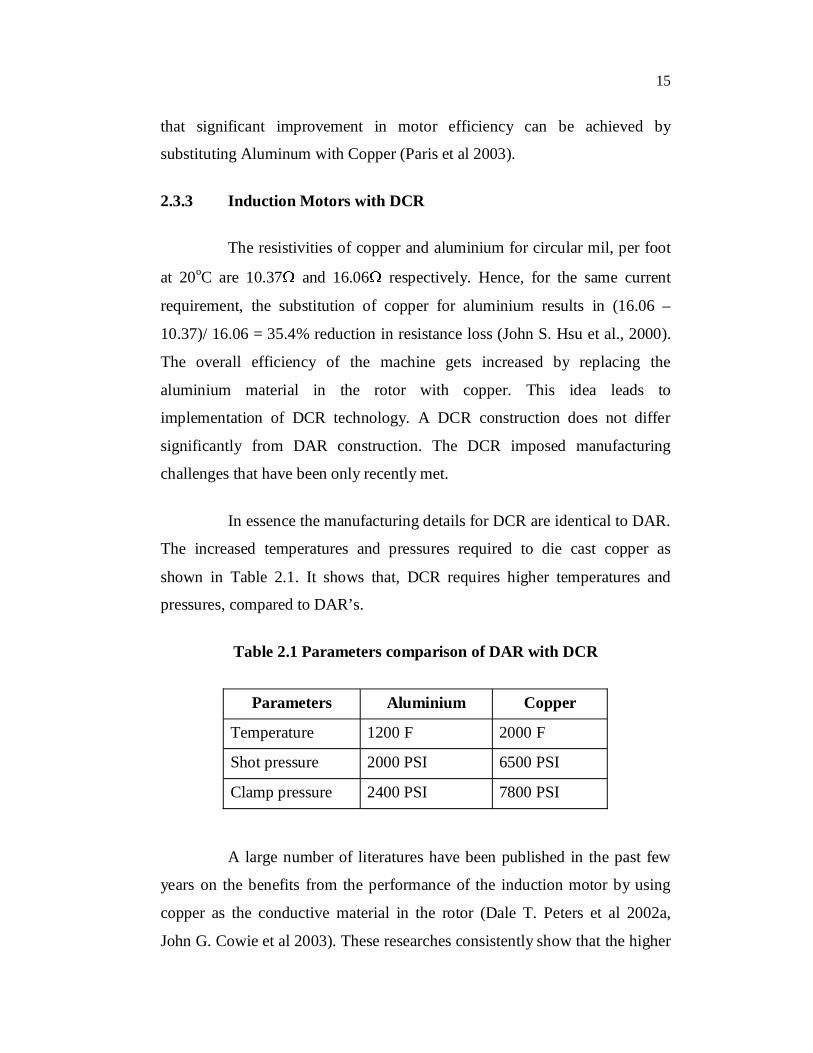
In essence the manufacturing details for DCR are identical to DAR.
The increased temperatures and pressures required to die cast copper as
shown in Table 2.1. It shows that, DCR requires higher temperatures and
pressures, compared to DAR’s.
Table 2.1 Parameters comparison of DAR with DCR
Parameters Aluminium Copper
Temperature 1200 F 2000 F
Shot pressure 2000 PSI 6500 PSI
Clamp pressure 2400 PSI 7800 PSI
A large number of literatures have been published in the past few
years on the benefits from the performance of the induction motor by using
copper as the conductive material in the rotor (Dale T. Peters et al 2002a,
John G. Cowie et al 2003). These researches consistently show that the higher
16
electrical conductivity of copper compared to aluminum results in higher
electrical energy efficiency of the machine by reduction in rotor I2R losses
and often through reduced stray load and windage and friction losses as well.
More efficient machine necessarily has lower slip and thus runs at a slightly
higher speed. But, when copper is simply substituted for aluminum, starting
or locked rotor torque is reduced and starting currents are higher. This can be
a problem in many applications. Recently, efforts to improve the starting
characteristics of the motor and to generally accommodate the design to better
utilize the high conductivity copper in the squirrel cage have been undertaken
(Kirtley et al 2004).
The DCR is constructed utilizing the following steps:
1. Stack rotor punching on a stacking mandrel
2. Insert punching /mandrel stack in end connector mold
3. Die cast (i.e., inject copper) rotor
4. Insert shaft into hot rotor core
5. Machining the rotor in order to remove the ingates resulting
from the injection of mould material.
6. Perfect balancing of the rotor assembly.
Therefore, it is well known that the incorporation of copper for the
rotor bars and end rings in the place of aluminium would result in attractive
improvements of motor efficiency (Dale T. Peter et al 2003a). In addition to
increase in efficiency, the copper adjusts with much more stability to
changing loads, especially at low speeds and at low frequencies. The
temperature rise in the rotor is very less which has the advantage of fewer
repairs and re-windings. So, the life of the motor is increased and the
17
maintenance cost is decreased. Due to the above advantages the DCR is
preferred over a CFR.
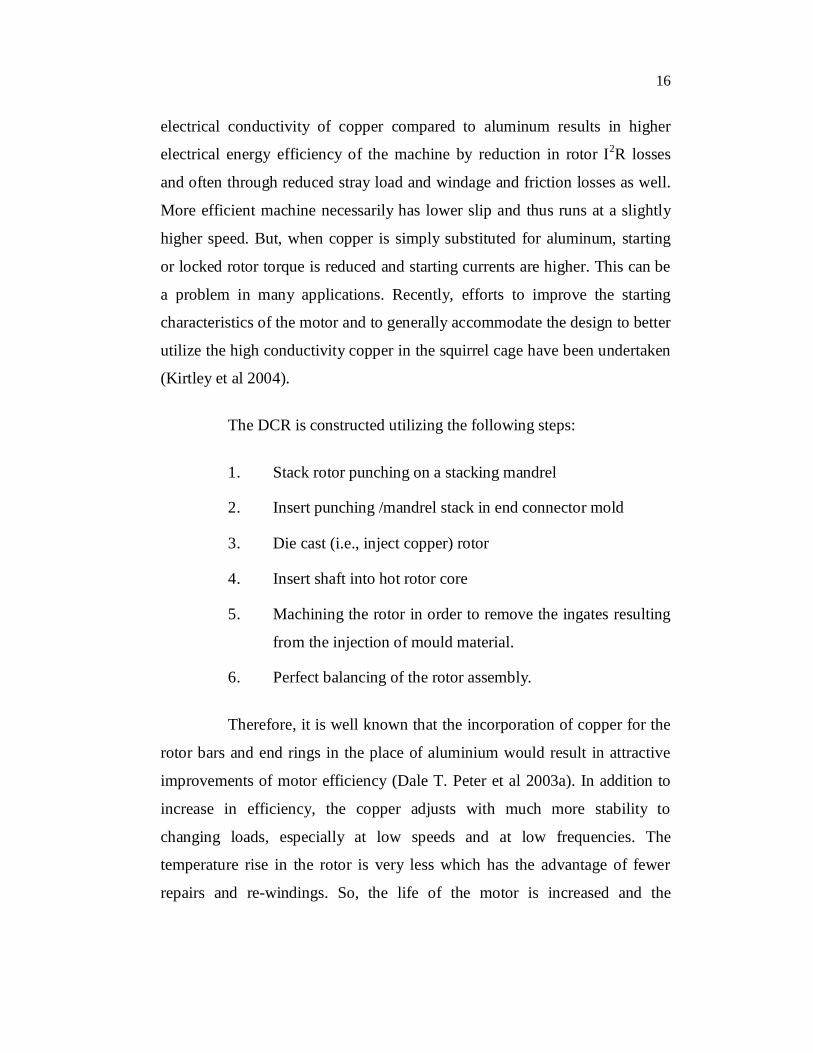
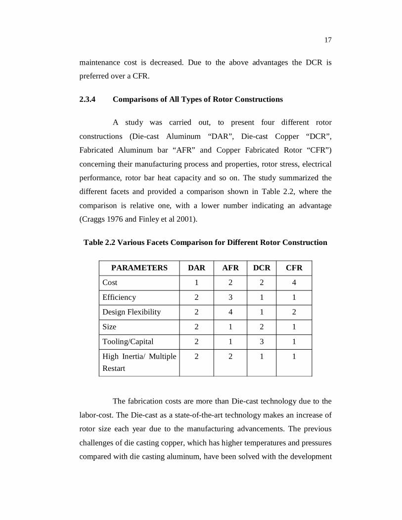
2.3.4 Comparisons of All Types of Rotor Constructions
A study was carried out, to present four different rotor
constructions (Die-cast Aluminum “DAR”, Die-cast Copper “DCR”,
Fabricated Aluminum bar “AFR” and Copper Fabricated Rotor “CFR”)
concerning their manufacturing process and properties, rotor stress, electrical
performance, rotor bar heat capacity and so on. The study summarized the
different facets and provided a comparison shown in Table 2.2, where the
comparison is relative one, with a lower number indicating an advantage
(Craggs 1976 and Finley et al 2001).
Table 2.2 Various Facets Comparison for Different Rotor Construction
PARAMETERS DAR AFR DCR CFR
Cost 1 2 2 4
Efficiency 2 3 1 1
Design Flexibility 2 4 1 2
Size 2 1 2 1
Tooling/Capital 2 1 3 1
High Inertia/ Multiple Restart
2 2 1 1
The fabrication costs are more than Die-cast technology due to the
labor-cost. The Die-cast as a state-of-the-art technology makes an increase of
rotor size each year due to the manufacturing advancements. The previous
challenges of die casting copper, which has higher temperatures and pressures
compared with die casting aluminum, have been solved with the development

18
of a die casting process using nickel-base alloy die inserts operated at elevated
temperature. Substantial progress in understanding and managing the porosity
problem, characteristic of high-pressure die-casting has also been pointed out
(Dale T. Peters et al 2002b and 2003b). The integrity and reliability of DCR is
just as good as in DAR. The primary reason why DCR’s are not common
place yet, is because it requires specialized equipment (investment) and
know-how in this field.
Active development of the Die-cast copper rotor motor begun in
1997 has now resulted in a growing market with about 2,50,000 units in
service and is still growing at a rapid rate. The DCR technology has been a
significant effort of the world copper industry through the International
Copper Association Ltd (ICA) managed by the Copper Development
Association (CDA). The DCR project has been conducted jointly with die
casters, motor manufacturers in all major motor markets word wide and
academia. A sizeable data bank of motor performance test results exists now,
illustrating the several advantages of using the DCR.
2.4 EFFICIENCY OF DCR MOTOR
A significant improvement in motor efficiency could be achieved
by substituting copper for aluminum in a Die-cast rotor for a squirrel cage
induction motor (Boglietti et al 2005; Dale T. Peters et al 2006 and Parasiliti
et al 2001 and 2005).
An economic comparison between aluminum and copper squirrel
cages was also made in the previous literatures (Poloujadoff et al 1995). They
concluded that when the initial cost is considered, the initial price of copper
cages is higher by 15%, but the savings in operating losses is seven or eight
times the increase in price. The use of DCR is one method enabling motor
efficiency to be increased as much as 1.5 % - 3 % above what is currently
19
possible using Die-cast aluminium rotor with out changing any other
parameters. These efficiency increases are expected to be higher on small
motors, decreasing 0.55% on larger designs.
Significant efficiency improvements could be attributed to adding
more copper to the windings, upgrading the laminations to premium-grade
low-loss steel, enhanced lamination designs, precision airgap between rotor
and stator, and reducing fan and other losses in the motor. Furthermore,
engineers from Baldor reviewed, design and production techniques, which are
required to fulfill the NEMA Premium efficiency standard, and introduced
new research being done to further improve efficiency level, including better
lamination steel slot designs and Die-cast copper rotors (John Malinowski
et al 2004). The efficiency level is upgraded mainly by reduction in stray load
loss and core loss as well as, some reduction in windage and friction losses. It
has been proved that DCR, together with optimized laminations could greatly
help to achieve higher efficiency economically (Koo et al 2007). A feature to
be noted is that, a reduction windage loss, which is normally accomplished by
reducing the external fan diameter, will greatly improve the efficiency of the
motor. Meanwhile the tradeoff is temperature rise in the winding, which will
lead to some increase in the stator resistance loss. Therefore, the designers
should always keep in mind to find a balance among the diverse losses so that
the overall motor performance is optimized.
2.4.1 Problems in DCR Technology and Solutions
The manufacturing details for DCR are identical to DAR. The
melting point for aluminum alloys is in the 676 C (1250 F) range. The
material used for the rotor’s die-casting mold is often H-13 tool steel, which is
not highly stressed at these temperatures. Die life can be in the thousands of
rotors depending on die complexity. Copper melts at 1083 C (1982 F). This
high melting temperature results in failure of conventional die steels by
20
thermal fatigue of the surface (“heat checking”) in less than 100 shots
(Parasiliti et al 2004). The solutions to tooling issues related to die-casting of
copper have been identified and the tool life can be considered acceptable
now (Dale T. Peters et al 1999 and Sakhuja et al 2004). THT Presses, Inc has
demonstrated economical means to die cast copper utilizing equipment,
developed specifically for Copper Rotors Cast Vertically task (Dale T. Peters
et al 2002c and 2002d). The details about the THT approach are discussed.
The DCR is now being employed by several manufacturers as a cost-effective
way to achieve EPAct and Eff1 efficiency levels or to reach or exceed NEMA
Premium levels (Thieman et al 2007). SEW Eurodrive and Siemens AG in
Germany, in particular, have made extensive investments to optimally design
the motor while copper in the rotor. The comparison or test for different
power ratings of motors (Most of these motors are SEW’s DT/DTE and
DV/DVE series) have been discussed, together with some summaries about
the achievement and optimal designs (Brush et al 2003; Kimmich et al 2005;
Stark et al 2005 and Kirtley et al 2007). Consequently, from the studies
above, it appears that the process of die casting copper rotors can be reliable
and robust. The motor total energy losses could be reduced by 15%~23%.
Further improvements in process and rotor design such as optimization of the
steel laminations and slot shape should extend copper’s lead in efficiency
over aluminum. (Update: Copper motor rotor (2001), Copper Development
Assoc., New York NY).
. The cost of DCR is higher by about 15 % as compared to the
motors of existing efficiency levels when replacing aluminium by copper die
casting without any other change. But the extra cost may prove to be nominal.
A copper rotor in a 15 HP motor could result in a 1.2% efficiency gain and
difference in retail list price of $10 to $12 per motor. For a $ 900 to $1,500
motor, the payback may be measured in months. In order to offset the cost of
the DCR following solutions are identified.
21
Development of dedicated motor design and configurations
of laminations optimized for DCR’s.
Identifying and sourcing of appropriate electrical steel for
the core packs.
For motors with DCR’s there is a need for a more perfect
technology of melting and die-casting. Then only mass-
production of rotors at an affordable cost is possible.
2.4.2 Advantages of DCR Technology
CDA-USA and ICA conducted many studies on the advantages of
DCR Technology. They came to a conclusion that improved efficiency at a
small increase in cost or alternatively reduced cost for the prevailing
efficiency levels, reduced temperature rise during operation, reduced
manufacturing cost and reduced weight could be achieved when applying
Die-cast copper instead of aluminum. Improving motor efficiency will bring
significant energy savings and improved conductor bar and end ring
consistency reduces the maintenance cost. Cooler running motor means
longer motor life (www.copper-motor-rotor.org).
2.4.3 Technical Issues
2.4.3.1 Starting torque
The copper rotor motor has the advantage of high torque at running
speed and its starting torque is lower than in aluminium rotor motors (85 Nm
instead of 90 Nm in a 5.5 kW motor), which is beneficial for gearbox life. In
applications where lower starting torque is a problem, a modified design of
the rotor slot offers a solution. It is found that the measured inter-bar
resistance is lower in DCR than in cast aluminium rotors. This leads to a
22
reduced pull-out torque and increased stray-load losses (Alexander Stening
et al 2008). For a continuous rated motor this cannot be a problem.
2.4.3.2 Higher start-up current
The higher conductivity of copper, i.e. its lower electrical
resistance, will result in a slightly higher start-up current as the slot area
remains the same. (7.0 times the nominal current for a 7.5 kW copper rotor
motor, instead of 6.0 times for its aluminum counterpart). Soft starter can be
used to avoid that this higher current aspects of the electricity system. Also,
since motors are increasingly being driven by inverters, inrush and starting
currents become less of an issue (Chiricozzi et al 2004).
2.4.3.3 Rotor inertia
The higher rotor weight increases rotor inertia. This improves the
motor's efficiency, but can be a problem in certain applications -for example,
motor’s that frequently switch direction at high speed. A survey among
manufacturers, users, researchers, engineers and members of associations,
revealed that the copper rotor motor has now become an accepted technology
(82%). A majority assess the technology ready for mass production (74%).
Higher efficiency (42%), lower heat production (24%) and reduced cost
(11%) are seen as major advantages. The main application domain is for
industrial low voltage induction motors of 1 up to 100 kW, but the technology
also has potential for fractional kW motors (De Keuleneer 2006).
2.5 HISTORY OF MOTOR EFFICIENCY STANDARDS
During the year 1992, Congress passed the Energy Policy Act
(EPAct), which granted the USA Department of Energy (DOE), the authority
to set minimum efficiency standards for certain classes of electric motors.
EPAct rules for motors became effective from Oct. 24, 1997. EPAct did not
23
create new efficiency performance levels but rather established a minimum
efficiency level in US. Upgrading motors from pre-EPAct level to EPAct
efficiency levels increases motor efficiency by 2.3 %. In 1994, NEMA issued
definitions for “energy efficient” motors. These motors must have nominal
efficiencies meeting or exceeding NEMA MGI. EPAct covers general-
purpose motors rated from 1 to 200 HP; 2-, 4- and 6-pole (3600, 1800 and
1200 rpm), horizontal, T-frame, single speed, continuous duty, 230V, 460V or
230/460V, NEMA Designs A and B. Efficiencies of these so-called "EPAct
motors" are from one to four percentage points higher than the previous
"standard-efficiency" motors.
NEMA revised MGI-1993 to include the specification of a design E
motor and they were specified to satisfy the International Electro technical
Committee (IEC) standards. These standards allow motors to be designed for
higher efficiency with lower restrictions on torque and starting current than
design B motors (NEMA standard publishing 1993).
In the year 1996, the Consortium for Energy Efficiency (CEE)
launched its Premium Efficiency Motors Initiative. Motors meeting the CEE
standards are designated as “CEE Premium EfficiencySM” which is 0.8-4%
more efficient than EPAct motors.
The European Union (EU) and Committee of European
Manufacturers of Electrical Machines and Power Electronics (CEMEP) have
developed a motor efficiency classification scheme for motors during the year
June 2000. Motors covered by this agreement are defined as totally enclosed
fan ventilated (IP 54 or IP 55) three phase A.C. squirrel cage induction motors
in the range of 1.1 to 90 kW, with 2- or 4-poles, rated for 400 V-line, 50 Hz,
S1, Duty Class, in standard design. Motors sold in Europe had an efficiency
marking, designated as EFF1 for their best efficiency, and EFF2 for standard
efficiency. There is a lower EFF3 level family of motors that the EU is
24
discouraging from being manufactured. Motor efficiency of EFF1 is
comparable to that of U.S. EPAct efficiency values (Bertoldi et al 2000). This
agreement should stimulate the Manufacturers in the development of new
ranges of high efficiency motors that requires an accurate motor design, the
adoption of new materials (e.g. premium steel) and Innovative technologies
(e.g. copper rotor cage die-casting) (Parasiliti et al 2002).
As a replica to the US position, the International Electrotechnical
Commission (IEC) proposed a standard referring to the energy efficiency
classes for electric motors (Tudorache et al 2009). By this standard IEC
intends to keep only the old Eff2 (IE1) and Eff1 (IE2) energy efficiency
classes (giving up the standard class Eff3) and to add another two classes with
even higher efficiencies, i.e., Premium Efficiency (IE3) and Super Premium
Efficiency (IE4). The replacement of standard electric motors with IE2 or
even higher energy efficiency class machines could entail important energy
savings (up to more than 3% of the total electric energy consumed worldwide)
and significant reduction of greenhouse gas emissions (Stanciu et al 2005).
The Government of India has already taken some important steps to
introduce policy measures in the form of the Energy Conservation Act 2001
to encourage the use of Energy Efficient products. The Act has notified 15
Industry sectors under the schedule of Energy Intensive Industries. To
compliment the market transformation, a standard and labeling program has
brought about a regulation on Minimum Efficiency Performance Standards
(MEPS) for energy intensive equipment including, industrial motors.
Based on the CEMEP classifications, the Indian Electrical and
Electronics Manufacturers Association (IEEMA) developed IEEMA-19:2000.
This formed the basis for the development of IS: 129615-2004 for Energy
Efficient Motors by the Bureau of Indian Standards. Table 2.3 shows the

25
comparison of efficiency levels as per different standards for a few 3 phase / 4
pole ratings.
On the Design and Development front, different measures are being
explored to achieve higher efficiencies in the motors in a cost effective way.
The International Copper Association along with the Common Fund for
Commodities and the United Nations Development Programme (UNDP), the
United Nations Development Programme - Global Environment Facility
(UNDP-GEF), is setting up an Enabling Technology Center (ETC) primarily
to commercialize the DCR technology useful for building cost effective High
Efficiency Motors.
In May 2001, NEMA announced a new motor efficiency standard-
NEMA PremiumTM efficiency. These motors are required to have 20% lower
losses than EPAct motors. NEMA PremiumTM applies to single-speed,
polyphase, 1 to 500 HP, 2-, 4-, and 6-pole (3600, 1800 and 1200 rpm) squirrel
cage induction motors, NEMA Designs A or B, 600V or less, (5 kV or less for
medium voltage motors), and continuous rated. In the month of June 2001,
NEMA and CEE agreed to align the NEMA PremiumTM and the CEE
Premium EfficiencySM efficiency levels to co-promote the standard.
After NEMA released the General Specification for Consultants,
Industrial and Municipal: NEMA Premium® Efficiency Electric Motors
(600 Volts or Less) in 2003, most of the major motor manufacturers put more
and more effort to meet or even to exceed the NEMA Premium® Efficiency
requirements. The intent of this specification is to outline the minimum
requirements for three-phase AC induction motors labeled with “Premium®”
applied to municipal and industrial applications for operation on voltages 600
volts or less, rated 500 horsepower or less, operating more than 2000 hours
per year at greater than 75 percent of full load.
26
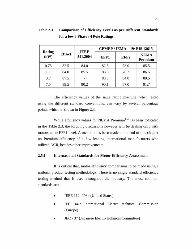
Table 2.3 Comparison of Efficiency Levels as per Different Standards
for a few 3 Phase / 4 Pole Ratings
Rating (kW) EPAct IEEE
841.2004
CEMEP / IEMA – 19/ BIS 12615
EFF1 EFF2 NEMA Premium
0.75 82.5 84.0 82.5 73.0 85.51.1 84.0 85.5 83.8 76.2 86.53.7 87.5 - 88.3 84.0 89.57.5 89.5 90.2 90.1 87.0 91.7
The efficiency values of the same rating machine, when tested using the different standard conventions, can vary by several percentage points, which is shown in Figure 2.3.
While efficiency values for NEMA PremiumTM has been indicated in the Table 2.3, the forgoing discussions however will be dealing only with motors up to EFF1 level. A mention has been made at the end of this chapter on Premium efficiency of a few leading international manufacturers who utilized DCR, besides other improvements.
2.5.1 International Standards for Motor Efficiency Assessment
It is critical that, motor efficiency comparisons to be made using a uniform product testing methodology. There is no single standard efficiency testing method that is used throughout the industry. The most common standards are:
IEEE 112 -1984 (United States)
IEC 34-2 International Electro technical Commission (Europe)
JEC - 37 (Japanese Electro technical Committee)
27
BS - 269 (British)
C-390 (Canadian Standards Association)
ANSI C50.20 same as IEEE 112 (United States)
IS 12615 – 2004 read with IS 4889 – 1968 (India)
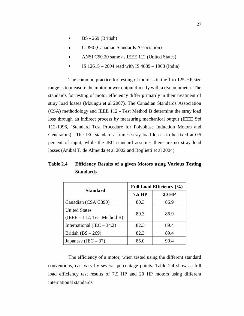
The common practice for testing of motor’s in the 1 to 125-HP size range is to measure the motor power output directly with a dynamometer. The standards for testing of motor efficiency differ primarily in their treatment of stray load losses (Mzungu et al 2007). The Canadian Standards Association (CSA) methodology and IEEE 112 - Test Method B determine the stray load loss through an indirect process by measuring mechanical output (IEEE Std 112-1996, ‘Standard Test Procedure for Polyphase Induction Motors and Generators). The IEC standard assumes stray load losses to be fixed at 0.5 percent of input, while the JEC standard assumes there are no stray load losses (Anibal T. de Almeida et al 2002 and Boglietti et al 2004).
Table 2.4 Efficiency Results of a given Motors using Various Testing Standards
Standard Full Load Efficiency (%)7.5 HP 20 HP
Canadian (CSA C390) 80.3 86.9 United States (IEEE – 112, Test Method B)
80.3 86.9
International (IEC – 34.2) 82.3 89.4 British (BS – 269) 82.3 89.4 Japanese (JEC – 37) 85.0 90.4
The efficiency of a motor, when tested using the different standard
conventions, can vary by several percentage points. Table 2.4 shows a full
load efficiency test results of 7.5 HP and 20 HP motors using different
international standards.
28
Although the IEC method is easy to use, it overestimates efficiencies by up to 2% for motors smaller than 10 kW and under estimates them slightly for motors larger than 700 kW. The IEEE is more accurate, but is not perfect either, because it relies on the accuracy of the torque transducer.
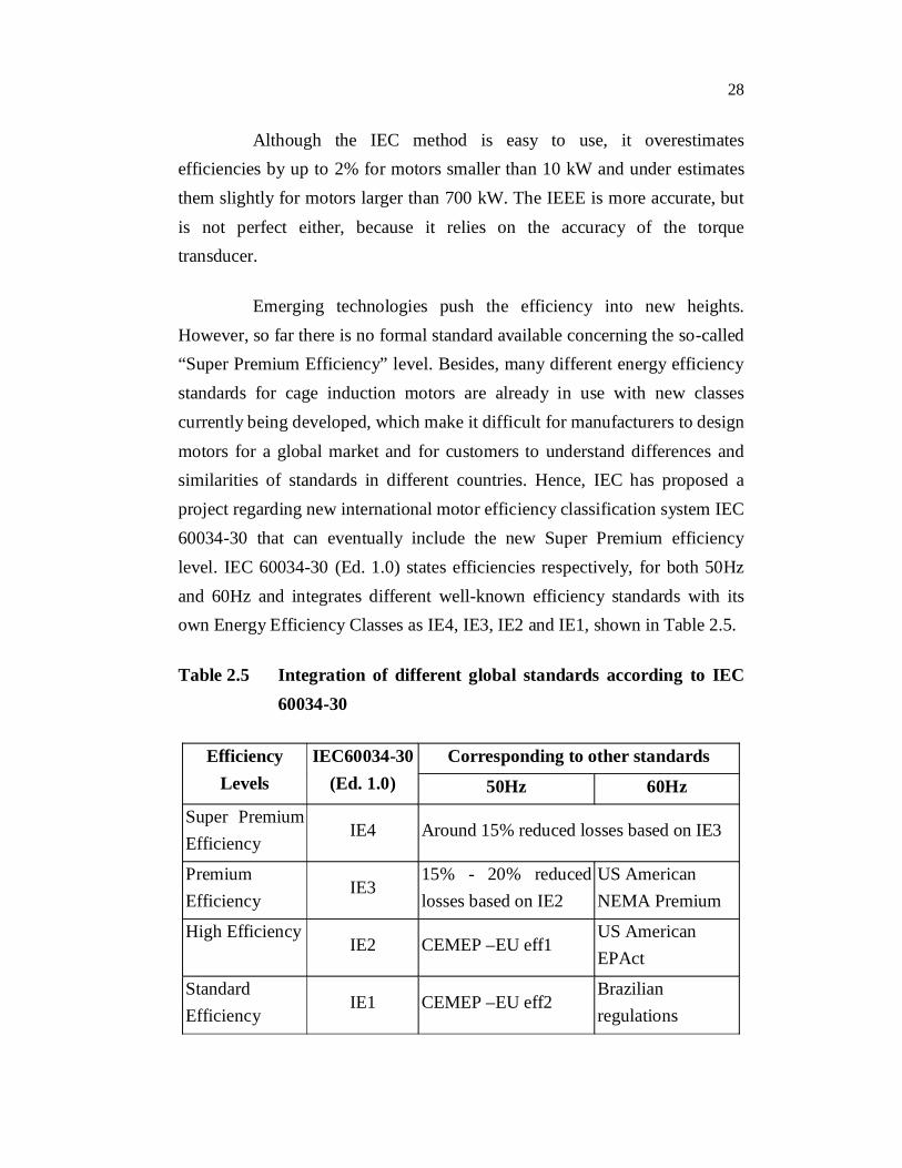
Emerging technologies push the efficiency into new heights. However, so far there is no formal standard available concerning the so-called “Super Premium Efficiency” level. Besides, many different energy efficiency standards for cage induction motors are already in use with new classes currently being developed, which make it difficult for manufacturers to design motors for a global market and for customers to understand differences and similarities of standards in different countries. Hence, IEC has proposed a project regarding new international motor efficiency classification system IEC 60034-30 that can eventually include the new Super Premium efficiency level. IEC 60034-30 (Ed. 1.0) states efficiencies respectively, for both 50Hz and 60Hz and integrates different well-known efficiency standards with its own Energy Efficiency Classes as IE4, IE3, IE2 and IE1, shown in Table 2.5.
Table 2.5 Integration of different global standards according to IEC 60034-30
Efficiency Levels
IEC60034-30 (Ed. 1.0)
Corresponding to other standards
50Hz 60Hz
Super Premium Efficiency
IE4 Around 15% reduced losses based on IE3
Premium Efficiency
IE315% - 20% reduced losses based on IE2
US American NEMA Premium
High EfficiencyIE2 CEMEP –EU eff1
US American EPAct
Standard Efficiency
IE1 CEMEP –EU eff2 Brazilian regulations

29
As shown below in Figure 2.3, it is observed that IE4 identifies the motor efficiency approximately from 88% to 97% compared with IE3’s 84% to 96% in the same output power scope (Conard U. Brunner 2007). One aspect needs to be clearly pointed out is that these advanced motors for IE4 usually require power electronics (frequency converters) to operate, and since grid frequency and the number of poles of converter-fed machines are not directly related to speed these motors are typically rated for a speed range and classified by torque rather than power, as described in IEC 60034-30 Ed. 1.0 draft.
Figure 2.3 Different efficiency levels comparison by CEMEP
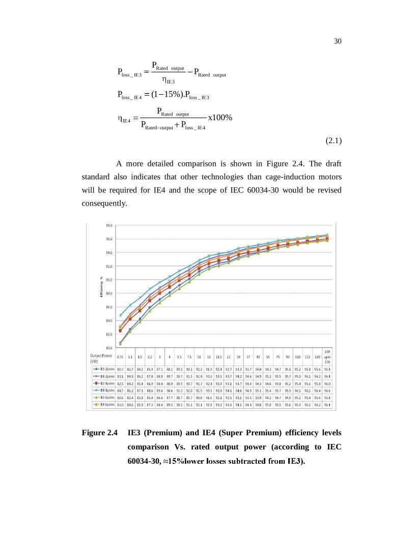
As one can see in Figure 2.3, there is approximately 1% difference between IE1 and eff2, also between IE2 and eff1, which is due to the fact that in the new testing standard, the additional (stray) load losses are determined from a test, whereas in CEMEP they were considered as flat 0.5% of input power and that is why the curve is called “Devalued curve”. In the latest edition of IEC 60034-30 (2008-04-30), the IE4 efficiency class could be defined by reducing the losses by 15% relative to IE3. Then, the efficiency for different output power rating could be calculated as:
30
Rated outputloss _ IE3 Rated output
IE3
loss _ IE 4 loss _ IE3
Rated outputIE4
Rated output loss _ IE4
PP P
P (1 15%).P
Px100%
P P
(2.1)
A more detailed comparison is shown in Figure 2.4. The draft standard also indicates that other technologies than cage-induction motors will be required for IE4 and the scope of IEC 60034-30 would be revised consequently.
Figure 2.4 IE3 (Premium) and IE4 (Super Premium) efficiency levels
comparison Vs. rated output power (according to IEC
60034-30,
31
In order to eliminate the scruples such as, premium efficiency
gained by compromise, other performance characteristics and the motor
reliability, a study was made based on similar enough motors and operation
conditions to compare the construction, performance and reliability for Pre-
EPAct, EPAct and Premium Efficient motors (Austin. H. Bonnett et al, 2008).
2.6 MARKET RESEARCH - AN OVERVIEW
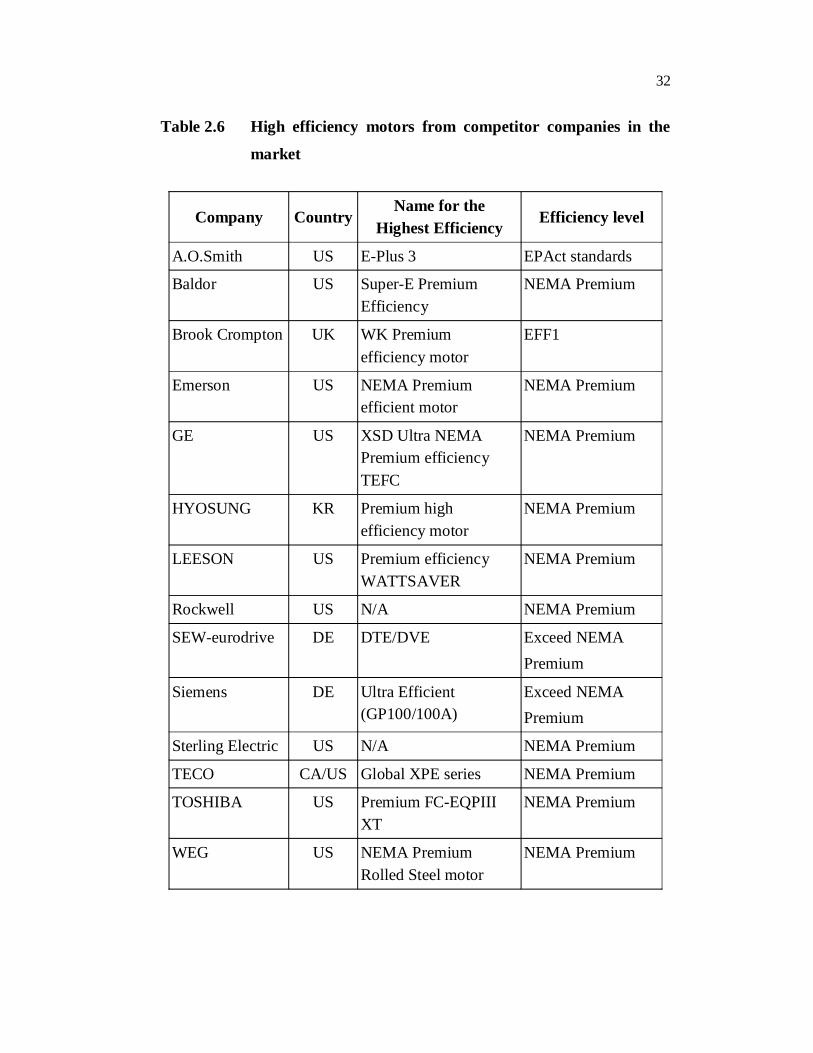
By going through various motor manufacturers’ product catalogs as
shown in Table 2.6, a conclusion could be made that leading manufacturers
are aiming to obtain even higher efficiency than NEMA Premium®. Baldor
seems to be striving to achieve the Super Premium Efficiency level, as one
could understand by taking a look at their Premium motors’ name, which is
Super-E® Premium Efficient Motor. The Baldor’s Super-E® motors meet or
exceed the efficiency levels defined by NEMA Premium®, however, there is
still some distance to the Super Premium Efficiency (IE4) requirement for
larger power rating. Baldor achieves the higher efficiency levels by a more
focused motor design, paying particular attention to the active materials,
whereas SEW and Siemens are already in the front-line. Leroy-Somer has
been making PM motors to replace the induction motors for some areas.
SEW-Eurodrive has been active in an extended effort to design the
motor to optimally use copper in the rotor to upgrade their DT/DV series to
DTE/DVE. Ultra Efficient TEFC motor of Siemens has the highlight feature
of a Copper Rotor (Siemens exclusive, leading-edge, DCR design), thus
Siemens motors have industry-leading efficiencies, as shown in Figure 2.5.
From Figure 2.5 it is seen that the efficiency levels are beyond NEMA
Premium level (Fuchsloch et al 2007).
32
Table 2.6 High efficiency motors from competitor companies in the
market
Company CountryName for the
Highest EfficiencyEfficiency level
A.O.Smith US E-Plus 3 EPAct standards
Baldor US Super-E Premium Efficiency
NEMA Premium
Brook Crompton UK WK Premium efficiency motor
EFF1
Emerson US NEMA Premium efficient motor
NEMA Premium
GE US XSD Ultra NEMA Premium efficiency TEFC
NEMA Premium
HYOSUNG KR Premium high efficiency motor
NEMA Premium
LEESON US Premium efficiency WATTSAVER
NEMA Premium
Rockwell US N/A NEMA Premium
SEW-eurodrive DE DTE/DVE Exceed NEMA Premium
Siemens DE Ultra Efficient(GP100/100A)
Exceed NEMA Premium
Sterling Electric US N/A NEMA Premium
TECO CA/US Global XPE series NEMA Premium
TOSHIBA US Premium FC-EQPIII XT
NEMA Premium
WEG US NEMA Premium Rolled Steel motor
NEMA Premium
33
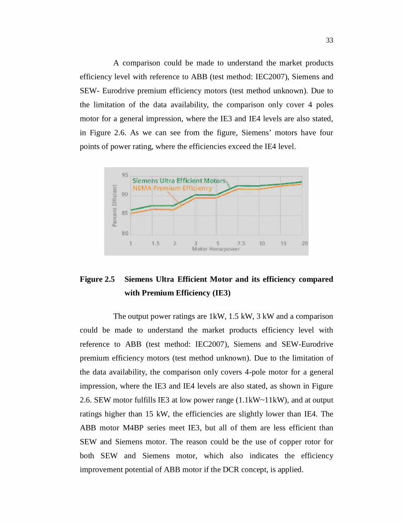
A comparison could be made to understand the market products
efficiency level with reference to ABB (test method: IEC2007), Siemens and
SEW- Eurodrive premium efficiency motors (test method unknown). Due to
the limitation of the data availability, the comparison only cover 4 poles
motor for a general impression, where the IE3 and IE4 levels are also stated,
in Figure 2.6. As we can see from the figure, Siemens’ motors have four
points of power rating, where the efficiencies exceed the IE4 level.
Figure 2.5 Siemens Ultra Efficient Motor and its efficiency compared
with Premium Efficiency (IE3)
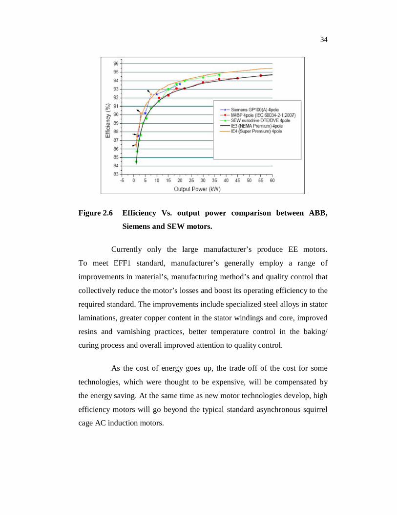
The output power ratings are 1kW, 1.5 kW, 3 kW and a comparison
could be made to understand the market products efficiency level with
reference to ABB (test method: IEC2007), Siemens and SEW-Eurodrive
premium efficiency motors (test method unknown). Due to the limitation of
the data availability, the comparison only covers 4-pole motor for a general
impression, where the IE3 and IE4 levels are also stated, as shown in Figure
2.6. SEW motor fulfills IE3 at low power range (1.1kW~11kW), and at output
ratings higher than 15 kW, the efficiencies are slightly lower than IE4. The
ABB motor M4BP series meet IE3, but all of them are less efficient than
SEW and Siemens motor. The reason could be the use of copper rotor for
both SEW and Siemens motor, which also indicates the efficiency
improvement potential of ABB motor if the DCR concept, is applied.
34
Figure 2.6 Efficiency Vs. output power comparison between ABB,
Siemens and SEW motors.
Currently only the large manufacturer’s produce EE motors.
To meet EFF1 standard, manufacturer’s generally employ a range of
improvements in material’s, manufacturing method’s and quality control that
collectively reduce the motor’s losses and boost its operating efficiency to the
required standard. The improvements include specialized steel alloys in stator
laminations, greater copper content in the stator windings and core, improved
resins and varnishing practices, better temperature control in the baking/
curing process and overall improved attention to quality control.
As the cost of energy goes up, the trade off of the cost for some
technologies, which were thought to be expensive, will be compensated by
the energy saving. At the same time as new motor technologies develop, high
efficiency motors will go beyond the typical standard asynchronous squirrel
cage AC induction motors.
35
2.7 INDIAN SCENARIO FOR ADOPTION OF DCR MOTOR
India, the world’s second largest emerging energy market (after
china), faces a chronic energy shortage say up to 20% during peak periods
while energy use is growing multifold. The problem is especially felt in rural
areas, where 63% of households do not have any electricity at all. One step
towards meeting this need was taken by the International Copper Promotion
Council India (IPCPI), which is supported in part by a grant from an arm of
the Small Scale Industries Development Bank of India and funded by the
USAID Eco Project. The Council tested copper rotors in motor’s used for
pumping water, one of the country’s leading agricultural uses for electricity.
2.7.1 ICPCI Project at Coimbatore Motors and Pumps Cluster
Coimbatore, popularly known as Manchester of South India, is
situated in the western part of the state of Tamil Nadu. It is well known for its
textile industries and has excellent potential for industrial growth. An Indian
company in Coimbatore, has developed Asia’s first ever-copper rotor in
motor’s to help conserve energy. After two years extensive research, during
the year 2002, the Tirupur based company succeeded in developing a copper
Die-cast rotor motor to replace aluminium cast rotor. Mehala Machines India
Ltd, based in Coimbatore has replaced aluminium rotors with copper as the
other good conductors.
In order to test the reliability of Indian made Die-cast Copper
Rotors and confirm the gains and performance in various other important
parameters, a project was conceived and carried out in Coimbatore Motors
and Pumps cluster by International Copper Promotion Council (India) –
ICPCI during the year 2003. Small Industries Development Bank of India
(SIDBI) and Technology Bureau for Small Enterprises (TBSE) provided
Motors and Pumps cluster by ICPCI. Small Industries Development Bank of
36
India (SIDBI) and Technology Bureau for Small Enterprises (TBSE) provided
assistance for the same.
Nexant Inc. (USA) helped in developing the concept and in
formulating the various dimensions, schedules and so on for the project.
Institutions like Coimbatore District Small Scale Industries Association
(CODISSIA) and The Southern India Engineering Manufacturers' Association
(SIEMA) played active roles in helping the industry grow and prosper with
the help of institutions like SIDBI and National Small Industries Corporation
Ltd. (NSIC). The facilities like Testing Center called Small Industries Testing
and Research Center (SITARC) established by the cluster members has
rendered testing support.
Ratings and types of motors that were chosen covered industrial
sector, agricultural sector as well as domestic applications. The samples
include single and three phase types of a.c. motors as well as, ratings and
types presently used in both Die-cast aluminum rotors and Copper Bar rotors.
The ten Die-cast copper rotors, for the eight ratings of motors chosen were
sourced from an Indian manufacturer, based on the drawings and the supply
of rotor stampings by the various manufacturers, participating in the project.
These were assembled into motors and then were assembled with the
conventional type of rotors used by them for performing comparative tests.
These tests were carried out in the respective factories and some samples from
each of the ratings were subjected to exhaustive tests at SITARC. Field tests
were also conducted later to confirm performance and reliability under actual
field conditions.
Based on experimental tests, the average improvement in efficiency
variation of the motors between the ratings 0.5 HP – 5 HP with Die-cast
copper rotors in comparison with Die-cast Aluminium rotors, a rise in
efficiency of 2.5 to 3.0 % points is achieved.