
IAS Menu - QR Electronic Menu for your business with powerful marketing tools
Chapter 10 Using Auxiliary Tools
C H A P T E R C O N T E N T S
10
Tools Menu 514
Section 1 Graphic Editor ........................515Overview 516File Menu 517Edit Menu 520Graphics Menu 522Options Menu 528Window Menu 530Library Edit Buttons 531Manipulating Graphics 532Create New Graphics and
Libraries 533Naming a Graphic 534
Graphic Tools Button Bar 535Editing a Library Graphic 551
Section 2 Expression Search ................ 553Expression Search Sub-Menu
Choices 554Find Expression 555Replace Expression 556Important Notes Regarding
Expression Searches 558
Section 3 AutoBuild ................................ 559
Section 4 Options ................................... 561
ProModel User’s Guide 513

Chapter 10 Using Auxiliary Tools10
.0.1
odel
for
ata.
on
m-
10.0.1 Tools Menu
The Tools Menu gives you access to two powerful tools to help you through the mbuilding process.
Graphic Editor Allows you to create, edit, rearrange, or delete library graphics use as entities, locations, resources and background graphics.
Stat::Fit Launches Stat::Fit and allows you to fit analytical distributions to user d
Expression Search Allows you to perform global search and replace functions expressions throughout any part of the model.
AutoBuild This option will guide you through the model building process and siulation steps by prompting you to define the basic model elements.
Options Allows you to set various directory and display defaults.
514 ProModel User’s Guide

Section 10.1 Graphic Editor
10.1
s ary phic.
10.1 Graphic EditorThe Graphic Editor allows you to create, edit, rearrange, or delete library graphicwithin a particular graphics library file. You can also copy graphics from one librto another. Graphics from several libraries can even be merged into a single graEach graphics library is saved with the grid size and scaled used to create the graphics.
Access the Graphic Editor from within ProModel:
• Select Graphic Editor from the Tools menu.
Access the Graphic Editor from the Program Manager:
• Double click the Graphic Editor icon in the ProModel Group. This method allows you to use the Graphic Editor as a separate application from ProModel.
� How To
� How To
ProModel User’s Guide 515

Chapter 10 Using Auxiliary Tools10
.1.1
c ng
ding )
a
e rt
-lip
10.1.1 Overview
The Graphic Editor consists of a menu bar, a Graphic Tools button bar, a GraphiLibrary menu, Library Edit buttons, an Edit window, and a set of icons representithe graphics in the graphics library.
Each of the tools in the Graphic Tools button bar is discussed in this section, incluthe procedures for creating and editing a graphic’s components (called “objects”using the drawing tools.
Graphic Editor Menus
The Graphic Editor menu bar includes the following menus:
File The File menu allows you to open a graphics library for editing and savingcurrent library. It also allows you to print a single graphic or an entire library.
Edit The Edit menu provides functions for selecting and duplicating one or morobjects that comprise a library graphic. In addition, it provides functions to impoand export graphics from other applications.
Graphics The Graphics menu is for manipulating one or more objects that comprise a library graphic. With this menu, you can group several objects together, f
Graphic Tools Button Bar Library Edit Buttons
Edit Window
Graphic Icons
516 ProModel User’s Guide

Section 10.1 Graphic Editor
10.1
.2
n
ou jects
phic
-. It is
iew
ph-
ed
u for
ry
and rotate objects, and alter the color, fill pattern and line style of objects. You caalso adjust the dimensions of the entire graphic.
Options The Options menu controls the editing environment. With this menu ycan use a grid to help you align component objects, edit that grid, and require obto snap to it. Finally, the Options menu allows you to zoom in and out on the graso you can edit the graphic at different sizes.
Window The Window menu allows you to arrange the windows (or iconized windows) currently displayed on the screen such that all windows are visible at oncealso allows you to bring any individual window to the forefront of the display. Thisparticularly useful when you are opening multiple graphic libraries and want to vall libraries simultaneously.
10.1.2 File Menu
New Creates an empty graphics library.
Open Brings up the Open Library Graphics dialog box for specifying which graics library file to retrieve. Graphics library files have the file extension GLB.
Close Closes the current graphic library. If the graphics library has been changsince the last save, you will have the option to save it.
Save Saves an open graphics library under the current file name or prompts yoa name if the graphics library has not been named.
Save As Brings up the Save As dialog box for saving the current Graphics librafile under a new filename. Graphic Library files have the file extension GLB.
ProModel User’s Guide 517

Chapter 10 Using Auxiliary Tools10
.1.2
s
.
her t
ne
reen
Print Graphic Prints the graphic in the Edit window only.
Print Library Prints the entire current graphic library.
Exit Quits the Graphic Editor with an option to save the current library if changehave been made since the last save.
Recently Opened Files Lists the five most recently retrieved graphics librariesSelecting one of these options will retrieve the listed graphics library.
Opening a Graphics Library File
All individual library graphics are loaded from and saved to the current graphics library, which, by default, is the one specified for the current model. However, otgraphic libraries may be opened for editing at any time. The name of the currenlibrary is displayed in the title bar of the window for each library. More than one library can be opened and viewed on the screen at a time. Opening more than ographic library simultaneously facilitates copying graphics between libraries.
Open another graphics library file:
1. Choose Open from the File menu.
2. Enter or select the name of the desired graphics library.
3. To view all open graphic libraries, choose Tile or Cascade from the Window menu.
A history list is given at the bottom of the File menu so you are able to quickly retrieve the last five libraries opened.
Closing a Graphics Library File
When you are finished working with a graphics library, you can close it to save scspace and memory. This option will not affect the graphic library used with any model.
Close a graphics library file:
• Choose Close from the File menu.
� How To
� Note
� How To
518 ProModel User’s Guide

Section 10.1 Graphic Editor
10.1
.2
ibrary
Saving a Graphics Library File
Once a graphic has been created or edited and placed in the current library, the lfile must be saved in order to make the changes permanent.
Save a graphics library file:
• Select Save from the File menu to save the library with the same name.
Save a graphics library file with a new name:
• Select Save As from the File menu to save the library with a new name.
Printing an Individual Graphic
Print an individual graphic:
1. Double click the mouse on the desired graphic’s icon, or select the graphic’s icon and click the Edit button.
2. Select Print Graphic from the File menu.
3. Choose the desired options from the resulting Print dialog box and click OK.
Printing an Entire Graphics Library
Print an entire graphics library:
1. Select Print L ibrary from the File menu.
2. Choose the desired print options from the Library Print dialog box and select OK.
If more than one graphic library is open, ProModel will print the active graphic library only.
� How To
� How To
� How To
� How To
� Note
ProModel User’s Guide 519

Chapter 10 Using Auxiliary Tools10
.1.3
a . To n
pasted
can
o n-
it
10.1.3 Edit Menu
Use the Edit menu for selecting and duplicating the individual objects comprisinglibrary graphic. You may also use it to exchange graphics with other applicationsuse the Edit menu functions, load the graphic you wish to edit by selecting its icofrom the library and clicking the Edit button, or double click the icon.
Cut Removes the selected object(s) and makes a temporary copy that may be back into the edit window later.
Copy Makes a temporary copy of the selected object(s) to be pasted later.
Paste Adds the most recently cut or copied object(s) to the current graphic.
Delete Deletes the selected objects from the current graphic.
Select All Selects all of the objects comprising the current graphic.
Copy to Clipboard Copies the entire graphic to the clipboard as a bitmap so it be pasted into other applications including word processors.
Paste WMF Pastes a Windows metafile (WMF) from the Windows clipboard intthe Edit window. You must have previously copied a Windows metafile to the Widows clipboard in another application.
Paste BMP Pastes a bitmap file (BMP) from the Windows clipboard into the Edwindow. You must first copy a bitmap file to the Windows clipboard.
Import Graphic Imports a WMF, BMP, PCX, or GIF file into the Edit window.
Export Graphic Exports the graphic in the Edit window to a WMF or BMP file.
520 ProModel User’s Guide

Section 10.1 Graphic Editor
10.1
.3
Importing a Graphic
Import a graphic into a graphic library:
1. Select the box to which you would like to add the graphic in the library. If you want to create a new graphic, choose the blank box at the end.
2. Select Import Graphic from the Edit menu.
3. Enter the name of the graphic you would like to import.
4. Select OK to close the import graphic dialog box.
5. Click on the Save button on the top right side of the library window.
Exporting a Graphic
Export a graphic:
1. Double click the mouse on the desired graphic’s icon, or select the graphic’s icon and click the Edit button.
2. Select Export Graphic from the Edit menu.
3. Enter a valid DOS name for the graphic in the resulting dialog box.
4. Click the OK button in the export graphic dialog box.
Copying a Graphic from One Library to Another
Copy an icon from one library to another library
1. Open both libraries.
2. Drag the graphic’s icon from the first graphic library to the second graphic library (preferably left to right).
3. Save the destination library by choosing Save from the File menu.
� How To
� How To
� How To
ProModel User’s Guide 521
Chapter 10 Using Auxiliary Tools10
.1.4
ry
st
he ed
ent in
90 ribed
e but-ition
tion orks
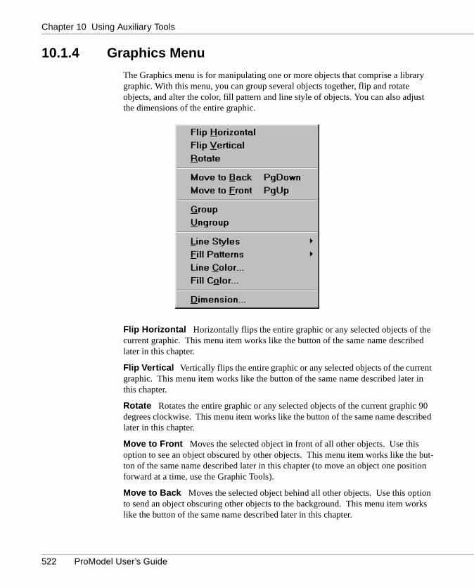
10.1.4 Graphics Menu
The Graphics menu is for manipulating one or more objects that comprise a libragraphic. With this menu, you can group several objects together, flip and rotate objects, and alter the color, fill pattern and line style of objects. You can also adjuthe dimensions of the entire graphic.
Flip Horizontal Horizontally flips the entire graphic or any selected objects of tcurrent graphic. This menu item works like the button of the same name describlater in this chapter.
Flip Vertical Vertically flips the entire graphic or any selected objects of the currgraphic. This menu item works like the button of the same name described laterthis chapter.
Rotate Rotates the entire graphic or any selected objects of the current graphicdegrees clockwise. This menu item works like the button of the same name desclater in this chapter.
Move to Front Moves the selected object in front of all other objects. Use this option to see an object obscured by other objects. This menu item works like thton of the same name described later in this chapter (to move an object one posforward at a time, use the Graphic Tools).
Move to Back Moves the selected object behind all other objects. Use this opto send an object obscuring other objects to the background. This menu item wlike the button of the same name described later in this chapter.
522 ProModel User’s Guide

Section 10.1 Graphic Editor
10.1
.4
.
e
rtical
olid
-
set-
l e an e
ether.
Group Combines or groups several objects into a single object for sizing and editing.
Ungroup Ungroups several grouped objects so they may be edited individually
Line Styles Allows the user to choose the line style including solid, dashed, linthickness, and optional arrowheads on either end of the line.
Fill Patterns Allows the user to choose the fill pattern for solid objects includingtransparent, slant, backward slant, grid, crosshatch, vertical, horizontal, solid, vegradient, and horizontal gradient.
Line Color Allows the user to choose the line color and create custom colors.
Fill Color Allows the user to choose the fill color and create custom colors for sobjects.
Dimension Brings up the Dimensions dialog box for defining the graphic dimension. The dimension can be height or width. The units can be feet or meters.
Line Styles, Fill Patterns, Line Color, and Fill Color set the feature and cause theting to be applied to the currently selected elements.
Group
When using the graphic tools to create an icon, it is often helpful to group severagraphics into a single graphic for editing purposes. For example, you may creaticon using the square, line, and circle tool and want to work with them as a singlitem.
Group objects together:
1. Use selector to select all objects you desire to group. Hold the shift key down to select more than one object at a time.
2. Choose Group from the Graphics menu.
3. Manipulate the group as necessary.
Ungroup
The Ungroup options allows you to ungroup several objects that are grouped tog
Ungroup previously grouped objects:
1. Use the selector to select the object you desire to ungroup.
2. Choose Ungroup from the Graphics menu.
� Note
� How To
� How To
ProModel User’s Guide 523

Chapter 10 Using Auxiliary Tools10
.1.4
Line
e
Line Styles
You may choose different styles for the lines and borders of objects by choosing Styles in the Graphic Editor Graphics menu.
Change the line style or border style of an object:
1. Select the desired object(s) using the Selector.
2. Choose Line Styles from the Graphic Editor Graphics menu.
3. Click on the desired style.
The arrowhead color is the same as the line color and is defined through the LinColor in the Graphics menu.
� How To
� Note
524 ProModel User’s Guide

Section 10.1 Graphic Editor
10.1
.4
e
Fill Patterns
Various patterns may be used to fill each object by choosing Fill Patterns from thGraphic Editor Graphics menu.
Change the fill pattern of an object:
1. Select the desired object(s) using the Selector.
2. Choose Fill Patterns from the Graphic Editor Graphics menu.
3. Click on the desired fill pattern.
� How To
ProModel User’s Guide 525

Chapter 10 Using Auxiliary Tools10
.1.4
ions in-
Line and Fill Color
You may also select a custom color for your lines and graphics.
Change line or fill color
1. Select the line or graphic you want to change.
2. Choose Line C olor or Fill Co lor from the Graphics menu.
3. From the dialog below, click on the color you wish to use.
Dimension
You can define the height or width of an object in feet or meters from the DimensDialog box. This will determine how large the graphic appears when placed on amodel layout. For example, to change the width of a graphic loaded in the Edit wdow to 5.00 feet, enter the following in the Dimensions dialog box:
� How To
526 ProModel User’s Guide

Section 10.1 Graphic Editor
10.1
.4
e
and
fine n-ns
ari-
Change the graphic’s dimensions:
1. Load a graphic into the Edit window.
2. Select Dimension from the Graphics menu.
3. Enter the new graphic dimension and click OK.
For example, a graphic of a monitor is displayed in the Graphic Edit window. Thsize of the graphic in the Graphic Edit window is 1.40 x 1.00 as shown below.
However, the monitor is really 2 feet wide. To change the graphic’s dimensions,select Dimension from the Graphics menu. Type 2 for the horizontal dimension click OK.
Notice the vertical dimension is automatically adjusted to 1.43. You can only deeither the horizontal or vertical dimension of the graphic. If you define one dimesion, the software will automatically calculate the other according to the proportioof the graphic in the Edit window. If you know the graphic is actually 2.00 x 1.50feet, you will need to adjust the proportions of the graphic accordingly by using vous tools from the Tools button bar.
a How To
ProModel User’s Guide 527

Chapter 10 Using Auxiliary Tools10
.1.5
e a ally, the
f the On
on
.
.
but-ens
dots same
10.1.5 Options Menu
The Options menu controls the editing environment. With this menu you can usgrid to help you align objects, edit that grid, and require objects to snap to it. Finthe Options menu allows you to zoom in and out on the graphic so you can edit graphic at different sizes.
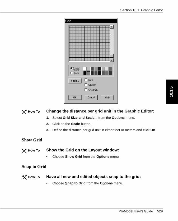
Grid Size and Scale Brings up the Grid dialog box for choosing the size, colorand visibility of the grid.
Show Grid Causes the grid to appear in the background for editing purposes. Igrid is on, choosing this option will turn it off. This is the same as choosing Gridin the Grid dialog box.
Snap to Grid Positions any object subsequently drawn or moved on the layoutthe nearest grid line. This option works whether the grid is visible or not.
Background Color Brings up the color dialog box for choosing a background color for the layout window.
Zoom Shrinks or enlarges your view of the graphic by the percentage selected
Grid Size and Scale
The grid size is changed by using the scroll bar to the right of the grid dialog boxMove the scroll bar up to increase the grid size and move the scroll bar down to decrease the grid size. To change the color of the fine grid lines, select the Oneston and choose a color. To change the color of the coarse grid lines, select the Tbutton and choose a color.
Instead of viewing boxes as the grid units, you may choose dots by selecting thebox. You may also choose to switch the grid, as well as the grid snap, on in this area.
528 ProModel User’s Guide
Section 10.1 Graphic Editor
10.1
.5
Change the distance per grid unit in the Graphic Editor:
1. Select Grid Size and Scale... from the Options menu.
2. Click on the Scale button.
3. Define the distance per grid unit in either feet or meters and click OK.
Show Grid
Show the Grid on the Layout window:
• Choose Show G rid from the Options menu.
Snap to Grid
Have all new and edited objects snap to the grid:
• Choose Snap to Grid from the Options menu.
� How To
� How To
� How To
ProModel User’s Guide 529
Chapter 10 Using Auxiliary Tools10
.1.6 itor
may g to
dow
ng
r.
Background Color
Change the Background Color of the Edit Window:
• Choose Background Color from the Options menu.
Zoom
Magnify a Graphic:
1. Choose Zoom from the Options menu.
2. Choose the level of magnification from the submenu.
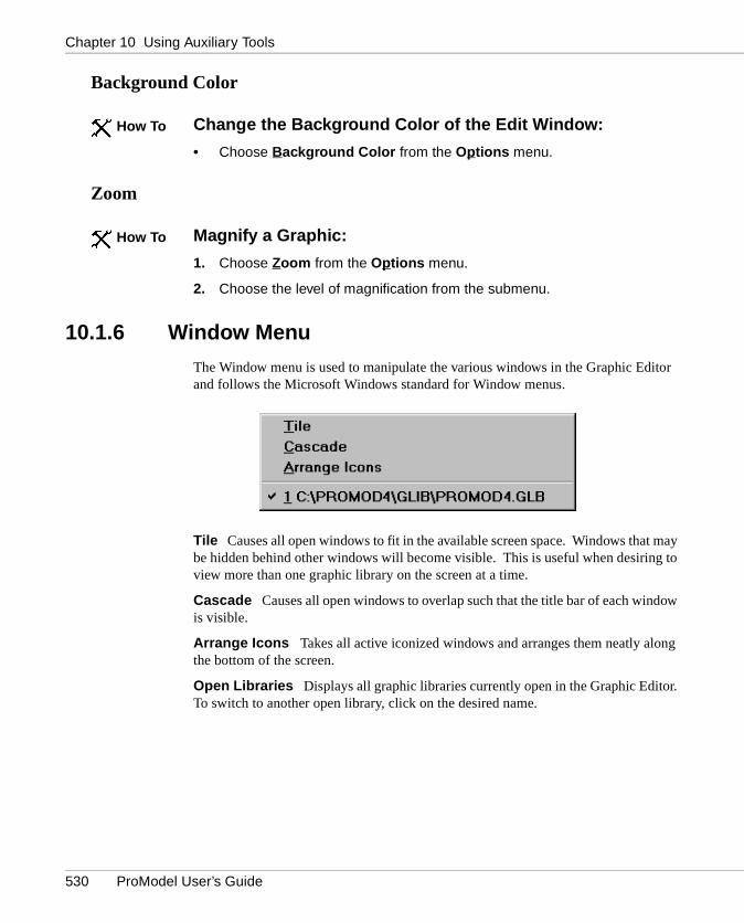
10.1.6 Window Menu
The Window menu is used to manipulate the various windows in the Graphic Edand follows the Microsoft Windows standard for Window menus.
Tile Causes all open windows to fit in the available screen space. Windows thatbe hidden behind other windows will become visible. This is useful when desirinview more than one graphic library on the screen at a time.
Cascade Causes all open windows to overlap such that the title bar of each winis visible.
Arrange Icons Takes all active iconized windows and arranges them neatly alothe bottom of the screen.
Open Libraries Displays all graphic libraries currently open in the Graphic EditoTo switch to another open library, click on the desired name.
� How To
� How To
530 ProModel User’s Guide

Section 10.1 Graphic Editor
10.1
.7
ar.
be her-ted.
10.1.7 Library Edit Buttons
The Graphic Editor contains four library edit buttons: Edit, Save, Delete, and Cle
Edit Retrieves a selected graphic from the library to the edit window.
Save Saves a graphic from the Edit window to the library. For a new graphic toadded to the library, the blank box at the end of the library must be selected. Otwise, the graphic in the Edit window will replace whichever graphic’s icon is selec
Delete Deletes the selected graphic from the library.
Clear Clears the contents of the edit window.
Edit a graphic:
• Double click on the graphic in the library. This method clears the contents of the Edit window before loading the new graphic.
or...
• Select the graphic by clicking once on the graphic and then click the Edit button. This method clears the contents of the Edit window before loading the new graphic.
� How To
ProModel User’s Guide 531

Chapter 10 Using Auxiliary Tools10
.1.8
red.
ple, a om-
10.1.8 Manipulating Graphics
Among other things, a graphic can be reduced, enlarged, combined, and reorde
Change a graphic’s size:
1. Select the graphic in the Edit window using the selector.
2. Choose Group from the Graphics menu.
3. Select one of the small gray boxes at the graphic edge to reduce or enlarge the graphic size. The selector will change to a cross-hair when you are near a gray box.
4. Drag the box to the desired size.
Several graphics can be combined together to create a single graphic. For examdesk and a chair are separate graphics but would be easier to use if they were cbined to form a single graphic.
Combine two graphics:
1. Load the first graphic into the edit window.
2. Drag the second graphic into the edit window.
3. Position and size the two graphics as desired.
4. Click the blank box in the Graphic Library.
5. Click the Save button.
Change the order of graphics in a graphic library:
• Drag a graphic to the desired location in the library.
� How To
� How To
� How To
532 ProModel User’s Guide

Section 10.1 Graphic Editor
10.1
.9
10.1.9 Create New Graphics and Libraries
Create a new graphic
1. Select Graphic Editor from the Tools menu.
2. Use the drawing tools to create the new graphic.
3. Click the Save button on the graphic editor.
4. The image appears at the end of the existing icons.
Create a new graphics library
1. Select Graphic Editor from the Tools menu.
2. Select New from the File menu.
3. Use the drawing tools to create any graphics you wish to use in your library. You may also copy and paste graphics from existing libraries.
4. After you finish preparing each new image, click the Save button on the graphic editor.
� How To
� How To
ProModel User’s Guide 533

Chapter 10 Using Auxiliary Tools10
.1.1
0
er f
such will
odel
tering ces, ert to
10.1.10 Naming a Graphic
Graphics can be named for resources, locations, and entities, or merely for easiidentification. When a named graphic is chosen while building a model, instead oentering a default name, such as Loc1, ProModel will enter the graphic’s name, as Lathe. If the name already exists for a location or resource graphic, a numberbe appended (e.g., Lathe1, Lathe2, etc.) If the name already exists for an entity graphic, a letter will be appended (e.g., PartA, PartB, etc.). This will make the measier to understand and use.
Name a graphic:
1. Enter the desired name at the bottom left of the screen, where it says “Name.”
2. Click the Save button to save the named graphic.
Correct syntax for location, resource, and entity names should be used when ena name in the Name field if the graphic is intended to represent locations, resouror entities. Graphic names are allowed to have spaces which automatically convunderscores “_” when used for locations, resources, or entities.
� How To
� Note
534 ProModel User’s Guide

Section 10.1 Graphic Editor
10.1
.11
h the
10.1.11 Graphic Tools Button Bar
The Graphic Tools Button Bar contains the tools necessary to create and edit a graphic’s component objects. The drawing tools are the main tools through whicgraphics are created and edited in the Editing window. The drawing tools includefollowing:
• Selector• Entity Spots• Text• Status Lights• Lines• Flip Horizontal• Arcs• Flip Vertical• Triangles• Rotate• Regular Squares and Rectangles• Cut• Rounded Squares and Rectangles• Copy• Circles and Ellipses• Paste• Chords• Step Back• Pies• Step Front• Polygons• Line Color• Raised Squares and Rectangles• Fill Color
ProModel User’s Guide 535
Chapter 10 Using Auxiliary Tools10
.1.1
1
f a
Selector
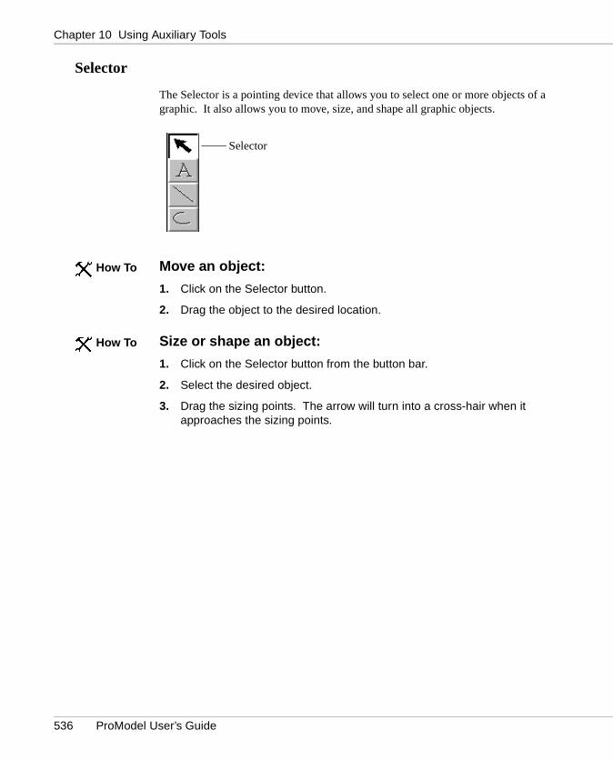
The Selector is a pointing device that allows you to select one or more objects ographic. It also allows you to move, size, and shape all graphic objects.
Move an object:
1. Click on the Selector button.
2. Drag the object to the desired location.
Size or shape an object:
1. Click on the Selector button from the button bar.
2. Select the desired object.
3. Drag the sizing points. The arrow will turn into a cross-hair when it approaches the sizing points.
Selector
� How To
� How To
536 ProModel User’s Guide

Section 10.1 Graphic Editor
10.1
.11
Text Tool
Text may be placed anywhere in the graphic by using the Text tool.
Place text in a graphic:
1. Select the Text tool from the button bar.
2. Click where the text is to appear. The Text dialog box will open.
3. Enter the desired text in the Text dialog box below. Set the desired options for the text. When finished, click the OK button.
Edit text already in the graphic:
• Double click on the text.
Text Tool
� How To
� How To
ProModel User’s Guide 537

Chapter 10 Using Auxiliary Tools10
.1.1
1
g the
Lines
Lines may consist of several segments and are drawn using the line tool.
Draw lines in the Graphic Editor:
1. Select the Line tool.
2. Click the left mouse button where the line is to begin.
3. Move the mouse to the end of the line segment.
4. Click the left mouse button to create a joint and begin the next segment.
5. Double click the left mouse button or click the right mouse button to end the line.
Lines can be drawn at 15 degree increments by holding the shift key while movinend of a line segment.
Line Tool
� How To
� Note
538 ProModel User’s Guide

Section 10.1 Graphic Editor
10.1
.11
bow
Arcs
Arcs are drawn using the Arc tool.
Draw an arc in the Graphic Editor:
1. Select the Arc tool from the Tools window.
2. Press the left mouse button at one end of the desired arc.
3. Drag the mouse to the other end of the arc and release the left mouse button.
To have the arc bow left, start the arc from the top and drag down. To have the arcright, start the arc from the bottom and drag up.
Arc Tool
� How To
� Note
ProModel User’s Guide 539

Chapter 10 Using Auxiliary Tools10
.1.1
1
Triangles
Triangles are drawn using the Triangle tool.
Draw a triangle in the Graphic Editor:
1. Select the Triangle tool from the Tools button bar.
2. Press the left mouse button where the center of the base of the triangle is to be located.
3. Drag the mouse until the triangle’s base is the desired size, but do not release the mouse button.
4. Press the shift key and move the mouse to adjust the size of the other two sides. Release the mouse button when done.
Triangle Tool
� How To
540 ProModel User’s Guide

Section 10.1 Graphic Editor
10.1
.11
ded
Squares and Rectangles
Squares and rectangles may be drawn using the regular rectangle tool, the rounrectangle tool, or the raised rectangle tool.
Draw a rectangle in the Graphic Editor:
1. Select either the regular, rounded, or raised rectangle tool from the Tools window.
2. Press the left mouse button at the top left corner of the desired rectangle.
3. Drag the mouse to the lower right corner of the rectangle and release the mouse button.
Draw a square in the Graphic Editor:
• Hold the shift key while drawing or editing a rectangle.
Rectangle
Rounded Rectangle
Raised Rectangle
� How To
� How To
ProModel User’s Guide 541
Chapter 10 Using Auxiliary Tools10
.1.1
1
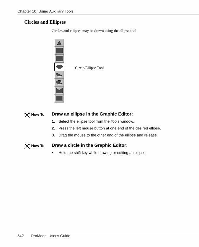
Circles and Ellipses
Circles and ellipses may be drawn using the ellipse tool.
Draw an ellipse in the Graphic Editor:
1. Select the ellipse tool from the Tools window.
2. Press the left mouse button at one end of the desired ellipse.
3. Drag the mouse to the other end of the ellipse and release.
Draw a circle in the Graphic Editor:
• Hold the shift key while drawing or editing an ellipse.
Circle/Ellipse Tool
� How To
� How To
542 ProModel User’s Guide

Section 10.1 Graphic Editor
10.1
.11
Chords and Pies
Chords and pies are drawn using the Chord tool and Pie tool.
Draw a chord or pie in the Graphic Editor:
1. Select the chord tool or pie tool from the tools menu.
2. Press the left mouse button at one end of the desired chord or pie.
3. Drag the mouse to the other end of the chord or pie and release the left mouse button.
Draw a circular chord or pie in the Graphic Editor:
• Hold the shift key while drawing a chord or pie.
Adjust the size of the “slice” in the chord or pie after the graphic has been drawn:
1. Select a corner of the “slice” on the graphic.
2. Press the left mouse button at the corner of the “slice.”
3. Drag the mouse to the desired position of the “slice” and release the left mouse button.
Chord Tool
Pie Tool
� How To
� How To
� How To
ProModel User’s Guide 543

Chapter 10 Using Auxiliary Tools10
.1.1
1
the
Polygons
Polygons are drawn using the Polygon tool.
Draw a polygon in the Graphic Editor:
1. Select the Polygon tool from the Tools window.
2. Click the left mouse button to begin the first point of the polygon.
3. Click the left mouse button at each successive point of the polygon.
4. Click the right mouse button or double click the left mouse button to end the polygon.
The sides of a polygon may be drawn at 15 degree increments by holding down shift key while moving the mouse to the next vertex.
Polygon Tool
� How To
� Note
544 ProModel User’s Guide

Section 10.1 Graphic Editor
10.1
.11
e two
ca-
ep-, the e
mber An sed pots
he ca-. If used for
for e . If th s t.
Positioning Spot
A positioning spot controls the positioning of an entity on a location, resource, orpath. It also controls the positioning of an entity or resource on a path. There artypes of positioning spots: entity spots and alignment spots.
Entity spots can be defined for a graphic in either the Graphic Editor or in the Lotions module. Alignment spots can only be defined for a graphic in the Graphic Editor. In the Graphic Editor, the button showing the red circle with the white X rresents the positioning spot. The default type is entity spot. To change the typeuser may double-click on the spot to display the Spot Type dialog. This allows thuser to define the type of positioning spot.
A graphic may have any number of entity spots. A graphic may also have any nuof alignment spots. However, only the first alignment spot defined will be used. entity or alignment spot is ignored if it is inapplicable for the model element it is uto represent. The following definitions explain uses of the entity and alignment sfor locations, entities, and resources.
Place a Positioning Spot on an icon:
1. Select the positioning spot tool from the button bar.
2. Click on the icon where the entity is to appear.
Location Graphics May only use entity spots. Whenever an entity arrives at tlocation, the entity graphic will be placed on the first entity spot defined for the lotion. The next arriving entity will use the entity spot defined second, and so forthentity spots are defined for a location graphic in the Locations module, they are ahead of any entity spots defined in the Graphic Editor. If no entity spot is definedthe location graphic, no entity is shown on the location.
Entity Graphics Use only alignment spots. When an alignment spot is definedan entity graphic, the entity graphic will be positioned so the alignment spot of thentity graphic and the entity spot for the location or resource graphic are alignedthe entity is traveling along a path, the entity graphic will move along the path withe alignment spot and the path segment or node aligned. If no alignment spot iplaced on an entity graphic, the center of the entity graphic is used for alignmen
Positioning Spot
� How To
ProModel User’s Guide 545

Chapter 10 Using Auxiliary Tools10
.1.1
1
g. An ravels pot rce
. A urrent s
Resource Graphics May use both entity spots and alignment spots. An entityspot on a resource graphic may be used to locate an entity a resource is carryinalignment spot can be placed on a resource graphic so that when the resource talong a path, the resource graphic will move along the path with the alignment sand the path segment or node aligned. If no alignment spot is placed on a resougraphic, the center of the graphic is used for alignment.
Status Lights
A status light is a circle that changes color depending on the status of a locationstatus light can be placed anywhere relative to a location to show the status or cstate of the location. At run-time a window can be displayed showing what statueach color represents.
Place a status light on an icon:
1. Select the Status Light tool from the button bar.
2. Click on the icon where the status light is to appear.
Status lights for location graphics may also be defined in the Locations Editor.
Status Light
� How To
� Note
546 ProModel User’s Guide
Section 10.1 Graphic Editor
10.1
.11
0
nder
d
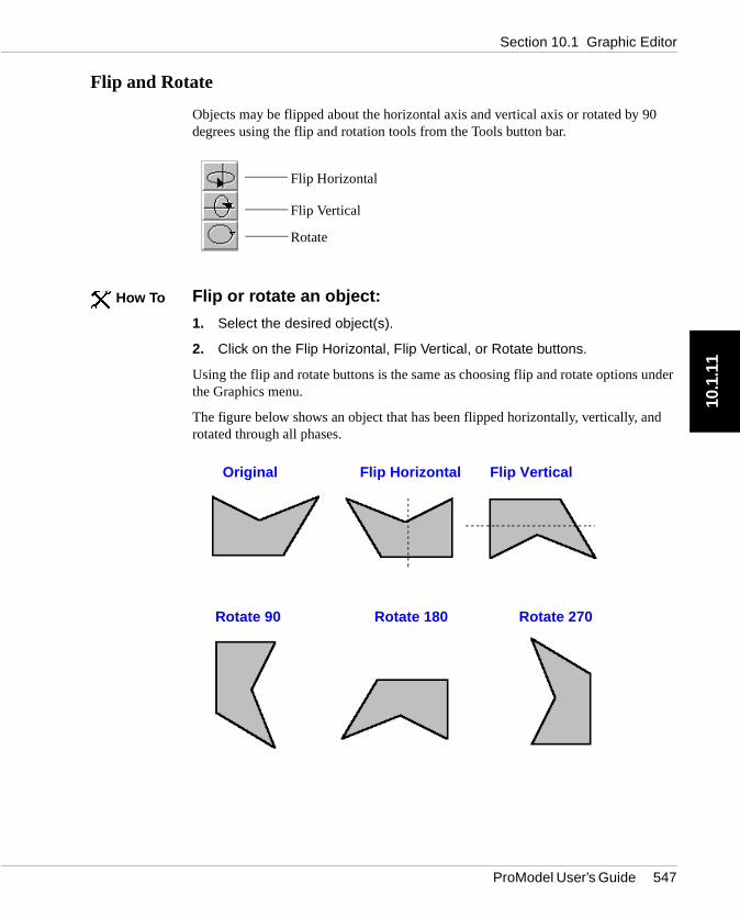
Flip and Rotate
Objects may be flipped about the horizontal axis and vertical axis or rotated by 9degrees using the flip and rotation tools from the Tools button bar.
Flip or rotate an object:
1. Select the desired object(s).
2. Click on the Flip Horizontal, Flip Vertical, or Rotate buttons.
Using the flip and rotate buttons is the same as choosing flip and rotate options uthe Graphics menu.
The figure below shows an object that has been flipped horizontally, vertically, anrotated through all phases.
Flip Horizontal
Flip Vertical
Rotate
� How To
Original Flip Horizontal Flip Vertical
Rotate 90 Rotate 180 Rotate 270
ProModel User’s Guide 547
Chapter 10 Using Auxiliary Tools10
.1.1
1
bjects the
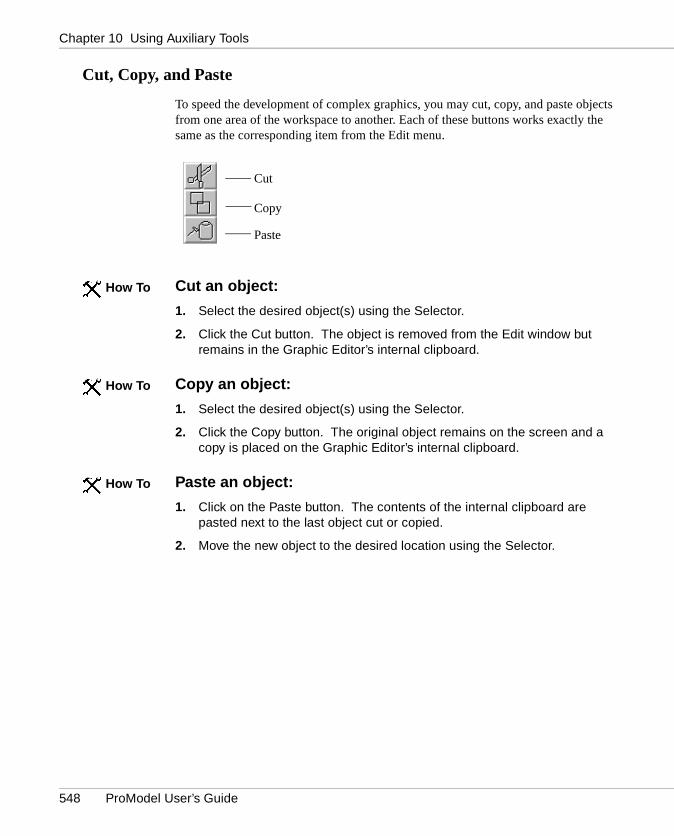
Cut, Copy, and Paste
To speed the development of complex graphics, you may cut, copy, and paste ofrom one area of the workspace to another. Each of these buttons works exactlysame as the corresponding item from the Edit menu.
Cut an object:
1. Select the desired object(s) using the Selector.
2. Click the Cut button. The object is removed from the Edit window but remains in the Graphic Editor’s internal clipboard.
Copy an object:
1. Select the desired object(s) using the Selector.
2. Click the Copy button. The original object remains on the screen and a copy is placed on the Graphic Editor’s internal clipboard.
Paste an object:
1. Click on the Paste button. The contents of the internal clipboard are pasted next to the last object cut or copied.
2. Move the new object to the desired location using the Selector.
Cut
Copy
Paste
� How To
� How To
� How To
548 ProModel User’s Guide

Section 10.1 Graphic Editor
10.1
.11
ion ion
ove n.
to Up
Step Back and Step Front
You can move an object behind or in front of another object. The Step Back optallows you to move a selected object behind another object. The Step Front optallows you to move a selected object in front of another object.
For example, suppose you have five graphic objects displayed and you want to mthe top object to the third object. You can use the Step Back or Step Front optio
Move an object behind or in front of another object:
1. Select the object to move using the Selector.
2. Click on the Step Back or Step Front tool from the button bar.
3. Continue to press the Step Back or Step Front button until the selected object is behind the desired object.
If you would like to move an object behind or in front of all objects, use the MoveBack or Move to Front option in the Graphics Menu. Alternatively, use the Pageor Page Down keys.
� How To
� Note
ProModel User’s Guide 549
Chapter 10 Using Auxiliary Tools10
.1.1
1
nu.
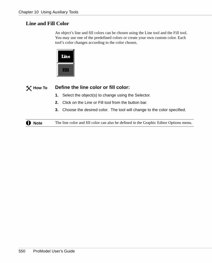
Line and Fill Color
An object’s line and fill colors can be chosen using the Line tool and the Fill tool.You may use one of the predefined colors or create your own custom color. Eachtool’s color changes according to the color chosen.
Define the line color or fill color:
1. Select the object(s) to change using the Selector.
2. Click on the Line or Fill tool from the button bar.
3. Choose the desired color. The tool will change to the color specified.
The line color and fill color can also be defined in the Graphic Editor Options me
� How To
� Note
550 ProModel User’s Guide

Section 10.1 Graphic Editor
10.1
.12
jects it a
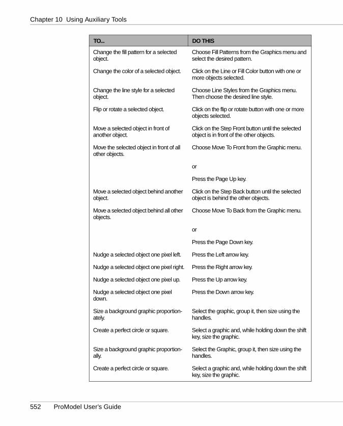
10.1.12 Editing a Library Graphic
Various editing functions allow you to alter the objects that comprise a library graphic. These functions may be applied to the entire graphic or to one of the obfrom which the graphic is constructed. The following is a description of how to edgraphic (All mouse actions are performed using the left button unless stated otherwise).
TO... DO THIS
Select an object. Choose the Selector tool and click on the object.
Select multiple objects. Drag in an empty region until a bounding rectan-gle encompasses the objects.
or
Shift+Click on each of the objects you want selected (Shift+Click again on a selected object deselects it).
Move one or more selected objects. Drag the selected object(s).
Delete selected objects. Press the Delete key.
or
Select Cut from the Edit menu (This method puts the object on the clipboard for subsequent past-ing).
Copy selected objects. Press the Copy button to copy the selected objects to the clipboard. Then press the Paste but-ton to place a copy of the selected objects into the Edit window.
or
Choose Copy from the Edit menu. Then choose Paste from the Edit menu.
Edit text. Double click on the text to bring up the text editor dialog box.
Change the shape of a selected object. Drag one of the sizing points of the selected object.
Add a vertex to a selected line or poly-gon.
Right click on the line or polygon where the vertex is to be added.
Delete a vertex of a selected line or polygon.
Right click on the vertex.
ProModel User’s Guide 551
Chapter 10 Using Auxiliary Tools10
.1.1
2
Change the fill pattern for a selected object.
Choose Fill Patterns from the Graphics menu and select the desired pattern.
Change the color of a selected object. Click on the Line or Fill Color button with one or more objects selected.
Change the line style for a selected object.
Choose Line Styles from the Graphics menu. Then choose the desired line style.
Flip or rotate a selected object. Click on the flip or rotate button with one or more objects selected.
Move a selected object in front of another object.
Click on the Step Front button until the selected object is in front of the other objects.
Move the selected object in front of all other objects.
Choose Move To Front from the Graphic menu.
or
Press the Page Up key.
Move a selected object behind another object.
Click on the Step Back button until the selected object is behind the other objects.
Move a selected object behind all other objects.
Choose Move To Back from the Graphic menu.
or
Press the Page Down key.
Nudge a selected object one pixel left. Press the Left arrow key.
Nudge a selected object one pixel right. Press the Right arrow key.
Nudge a selected object one pixel up. Press the Up arrow key.
Nudge a selected object one pixel down.
Press the Down arrow key.
Size a background graphic proportion-ately.
Select the graphic, group it, then size using the handles.
Create a perfect circle or square. Select a graphic and, while holding down the shift key, size the graphic.
Size a background graphic proportion-ally.
Select the Graphic, group it, then size using the handles.
Create a perfect circle or square. Select a graphic and, while holding down the shift key, size the graphic.
TO... DO THIS
552 ProModel User’s Guide

Section 10.2 Expression Search
10.2
in-.
d, the here ext
10.2 Expression SearchThe Expression Search feature is used to find or replace text entered into logic wdows and expression fields, such as location downtime logic or location capacityName fields can be found, but not replaced. Reference fields can be found and replaced. However, when the name of a location, resource, entity, etc. is changeuser will be prompted to automatically change all references to the new name. Tare three types of searches: Find expression, Replace expression, and Search Nexpression.
Perform an expression search:
• Select Expression Search from the Tools menu.� How To
ProModel User’s Guide 553
Chapter 10 Using Auxiliary Tools10
.2.1
ion
ll odel,
f the h
ent t
reak rigi- at the
10.2.1 Expression Search Sub-Menu Choices
Find
A dialog box gives you the following options after choosing Find from the ExpressSearch submenu:
Modules to Search Check the modules you want to search. “Other” includes aother edit tables and some dialog boxes where text is entered for defining the msuch as attributes or arrays.
Search Notes Check this box to include Notes fields in the text search.
Whole Words Only Check this box to search for only whole words or groups owhole words that match the text to find. For example, searching for “Attr” without Whole Words Only box checked will find “Attr1” and “Attr2” whereas a search witthe box checked would find neither.
Text to Find Enter the text expression you want to find.
Replace
Choosing replace gives you these options in addition to the find options:
Prompt on Replace Check this box if each time ProModel finds a match, you want ProModel to ask if you want that particular match changed to the replacemtext. The prompt will give you the option to replace that particular match, skip thaparticular match, or to cancel the search altogether.
New Text Enter the text you want to replace the search text.
Search Next
Choosing Search Next in the Expression Search submenu will resume the mostrecently canceled search. For example, suppose you begin a search and then bout of the search to adjust something in the model. If you want to continue the onal search, you can select Search Next and ProModel will start the search againplace you stopped searching.
554 ProModel User’s Guide

Section 10.2 Expression Search
10.2
.2
in a
dialog el
10.2.2 Find Expression
The Find Expression option allows you to find each occurrence of an expressionmodel.
Find an expression:
1. From the Tools menu, select Expression Search .
2. Select Find... from the submenu.
3. Supply the necessary details in the Find dialog box shown below. Clicking Select All or Deselect All button will check or uncheck every module.
4. Click OK.
Once the Expression Search has found the first occurrence of an expression, a box will appear giving information on exactly where the text was found. ProModwill then display the following dialog, including a box displaying the entire line onwhich the text was found, with the search expression highlighted.
a How To
ProModel User’s Guide 555

Chapter 10 Using Auxiliary Tools10
.2.3 ion in
Find the next match of a text expression:
• Click on Search A gain
10.2.3 Replace Expression
The Replace Expression option allows you to find each occurrence of an expressa model and replace that expression with a new expression.
Replace an expression with another expression:
1. Select Replace... from the Expression Search submenu.
2. Supply the necessary details in the Replace dialog box shown below. Clicking Select A ll or Deselect All button will check or uncheck every module.
� How To
� How To
556 ProModel User’s Guide

Section 10.2 Expression Search
10.2
.3
3. Click on OK. If you have chosen “Prompt on Replace,” ProModel will then display the following dialog box if it finds the text you specified.
4. Choose: Yes to change the text and search for the next match.Change All to change every match.No to skip this match and search for the next match.Go to Module to edit the text directly.Cancel to leave the match intact and stop searching.
ProModel User’s Guide 557

Chapter 10 Using Auxiliary Tools10
.2.4
r
ox.
omat-you in the
res-
e
, a .
ith to dis-t,
ange the the y.
10.2.4 Important Notes Regarding Expression Searches
1. Not every field of every module is included. Fields such as statistics, text ingraphics, or yes/no fields which may not be edited cannot be searched for oreplaced. To replace record identifiers, see number six.
2. Under “Modules to Search,” the Other option refers to information entered inplaces not listed in the dialog box, including the Simulation Options dialog b
3. Notes fields are not part of the actual model data, therefore they are not autically included in the search. Notes also include comments in the model. If want to search or replace Notes fields, then check the Search Notes option Find or Replace dialog boxes.
4. The Whole Words Only option interprets words loosely enough to distinguishwords not separated by spaces. For example, searching for “Attr1” in the expsion Attr1=Attr1+Attr2, would find both occurrences. You can search for expressions longer than a whole word, such as “Attr1=Attr1+Attr2,” as wholeword expressions. To find a portion of a name, like “Attr” in “Attr1,” deselect thWhole Words Only option.
5. Once the Expression Search has found the first occurrence of an expressiondialog box will appear giving information on exactly where the text was foundThis includes a box displaying the entire line on which the text was found, wthe search expression highlighted. In some cases the box may be too small play the entire line. To see the hidden portion of the text, left-click on the texand use the left and right arrow keys to scroll the text horizontally.
6. The Replace feature cannot be used to change an element identifier. To chall occurrences of a model element name (such as a location name), changename of the element where it is defined and all other expressions containingname, as well as any references to this record, will be changed automaticall
558 ProModel User’s Guide
Section 10.3 AutoBuild
10.3
ing
sev-ic ut of
the lly ls? ild ls.
his
o be
10.3 AutoBuildSelect the AutoBuild switch to have ProModel guide you through the model buildand simulation steps by prompting you to define the basic model elements.
The art of simulation modeling is mastered only through the process of building eral types of models. ProModel makes it easy for new modelers to learn the basapproach to modeling through the AutoBuild feature. This feature takes the fear omodeling by providing a structured model building environment.
The first question asked by new modelers is typically, “Where do I begin?” After goals and objectives of the model have been determined, it is time to start actuaentering data, but how? What should be entered first? Locations, Entities, ArrivaThe AutoBuild feature takes away the guess work by guiding you through the bumodules in the most logical sequence: locations, entities, processing, and arriva
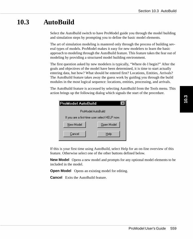
The AutoBuild feature is accessed by selecting AutoBuild from the Tools menu. Taction brings up the following dialog which signals the start of the procedure.
If this is your first time using AutoBuild, select Help for an on-line overview of thisfeature. Otherwise select one of the other buttons defined below.
New Model Opens a new model and prompts for any optional model elements tincluded in the model.
Open Model Opens an existing model for editing.
Cancel Exits the AutoBuild feature.
ProModel User’s Guide 559

Chapter 10 Using Auxiliary Tools10
.3
uto-
ro-onal
ild
od- make y d, exit nd
was
Using the AutoBuild Feature
When starting AutoBuild, an AutoBuild Options dialog appears, prompting you tocheck optional modules to be invoked by AutoBuild. If no options are checked, ABuild takes you only through the basic modules required to define a model (i.e., locations, entities, processing, and arrivals). Once you are in AutoBuild mode, PModel will prompt you to go through each of the standard modules plus any optimodules selected.
When you finish defining the information in a module, close the module. AutoBuwill then display a prompt and allow you to go to the next standard module.
AutoBuild is flexible enough to allow you to jump back and forth between build mules. Once the AutoBuild session has begun, you may enter any other module toadditions or changes and return to AutoBuild where you left off. To do this, simplselect another module and make the desired change or addition. When completethe module by closing the module window. The AutoBuild feature will take over areturn you to the next uncompleted module. For example, if the Entities module not complete, AutoBuild would return you to that module. Otherwise, AutoBuild would take you to the next uncompleted module.
GNote
560 ProModel User’s Guide
Section 10.4 Options
10.4
ild
l
x
f
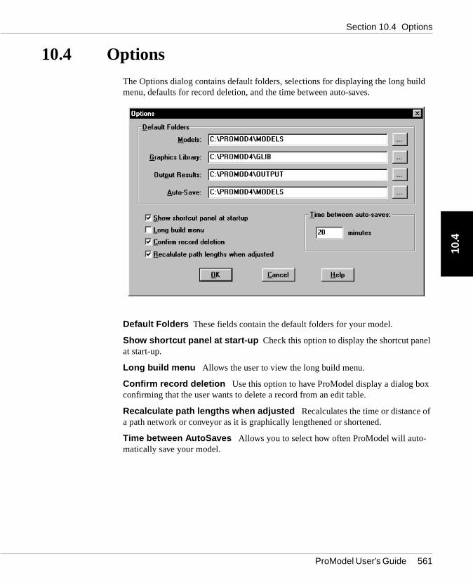
10.4 OptionsThe Options dialog contains default folders, selections for displaying the long bumenu, defaults for record deletion, and the time between auto-saves.
Default Folders These fields contain the default folders for your model.
Show shortcut panel at start-up Check this option to display the shortcut paneat start-up.
Long build menu Allows the user to view the long build menu.
Confirm record deletion Use this option to have ProModel display a dialog boconfirming that the user wants to delete a record from an edit table.
Recalculate path lengths when adjusted Recalculates the time or distance oa path network or conveyor as it is graphically lengthened or shortened.
Time between AutoSaves Allows you to select how often ProModel will auto-matically save your model.
ProModel User’s Guide 561

Chapter 10 Using Auxiliary Tools10
.4
and
kes This uild
Directories
The Directories section of the Settings dialog allows you to specify which drives folders to use for storing models, graphic libraries, and output results.
Change the default folders:
1. Select Options from the Tools menu.
2. Specify the desired folders for models, graphics libraries, output results, and auto-save.
3. Click OK.
Long Build Menu
The Long Build Menu option reorganizes the Build menu. The long build menu tathe first section of the More Elements submenu and places it in the Build menu. includes attributes, variables, arrays, macros, and subroutines. Using the long bmenu is especially helpful when using these elements frequently.
Display the long menu:
1. Choose Options from the Tools menu.
2. Check the Long build menu option.
To display the short menu, follow the same procedure above and uncheck the Long build menu option.
a How To
a How To
GNote
562 ProModel User’s Guide

Section 10.4 Options
10.4
l in called e
uto-
AutoSaving Files
ProModel automatically saves the open model every few minutes, which is usefuthe event of unforeseen crashes and power outages. ProModel uses a model file“AUTOSAVE.MOD” for all autosaves and only modifies the original file when Savis chosen from the File menu.
Specify the amount of time between AutoSaves:
1. From the Tools menu, select Options .
2. In the Time between autosaves field, enter the time.
3. Click OK.
Models are always autosaved at the start of a simulation run. To deactivate the asave feature, set the time between auto-saves to 0.
Specify the autosave directory:
1. From the Tools menu, select Options .
2. In the Auto-save field, enter the directory path you wish to use.
3. Click OK.
a How To
G Note
a How To
ProModel User’s Guide 563

Chapter 10 Using Auxiliary Tools10
.4
564 ProModel User’s Guide