Chapter 10 Three-Dimensional Veiwing ...shengbin/course/cg/lecture notes/CG10...Chapter 10...
52
Chapter 10 Three-Dimensional Viewing Computer Graphics
-
Upload
trinhkhanh -
Category
Documents
-
view
233 -
download
5
Transcript of Chapter 10 Three-Dimensional Veiwing ...shengbin/course/cg/lecture notes/CG10...Chapter 10...
Chapter 10Three-Dimensional Viewing
Computer Graphics

Chapter 10Three-Dimensional Viewing
Part I.Overview of 3D Viewing Concept
3D Viewing Pipeline vs. OpenGL Pipeline
3D Viewing-Coordinate Parameters
Projection Transformations
Viewport Transformation and 3D Screen Coordinates
2
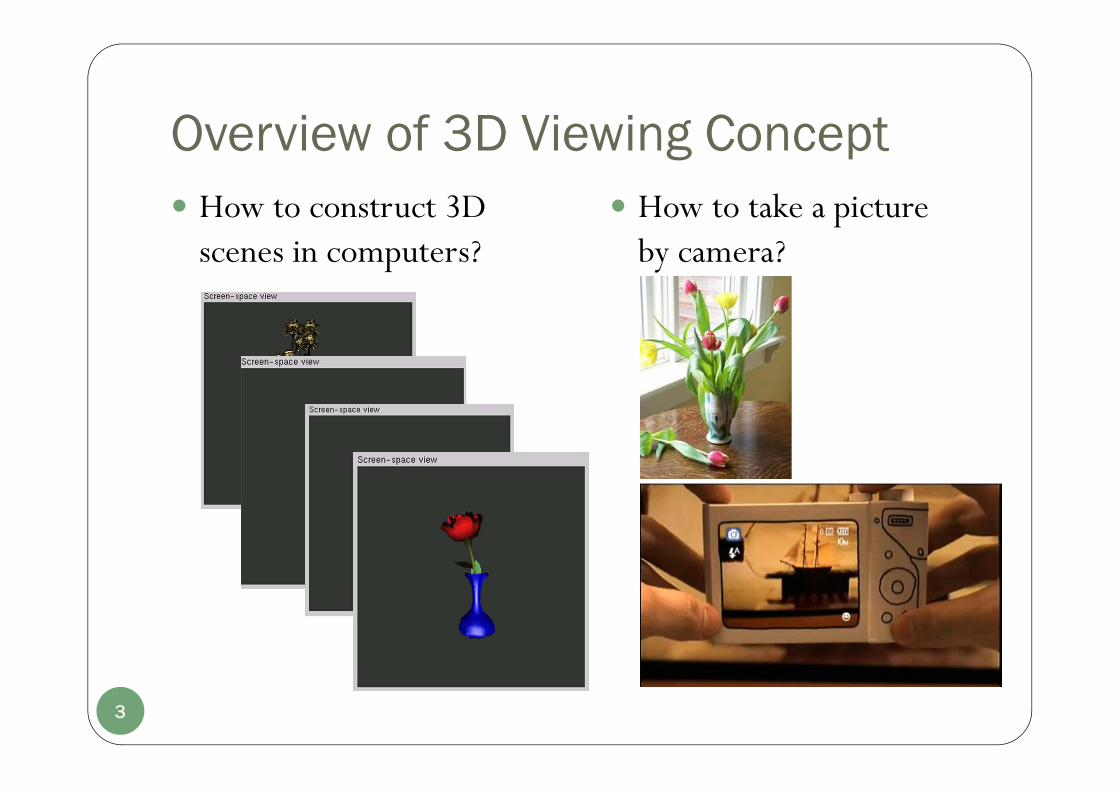
Overview of 3D Viewing Concept How to construct 3D
scenes in computers?
3
How to take a picture by camera?
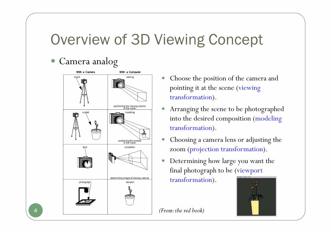
Overview of 3D Viewing Concept
Choose the position of the camera and pointing it at the scene (viewing transformation).
Arranging the scene to be photographed into the desired composition (modeling transformation).
Choosing a camera lens or adjusting the zoom (projection transformation).
Determining how large you want the final photograph to be (viewport transformation).
4 (From: the red book)
Camera analog

3D Viewing Pipeline vs. OpenGL Pipeline
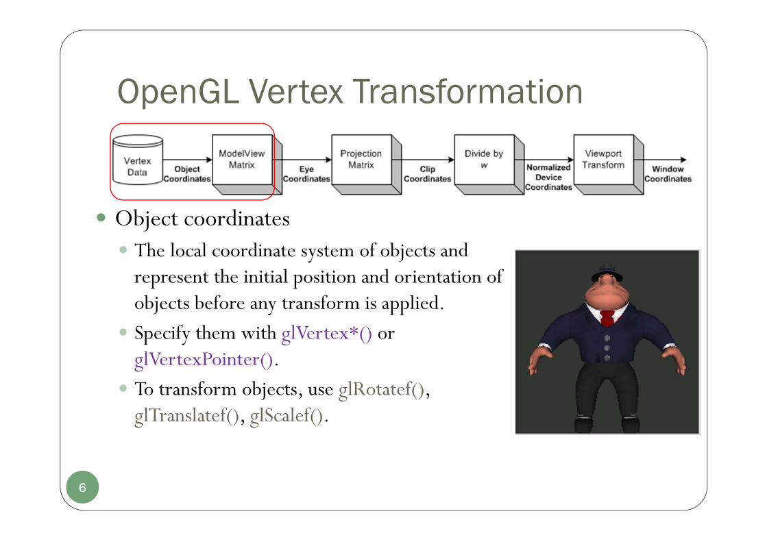
In OpenGL pipeline, geometric data such as vertex positions and normal vectors are transformed via Vertex Operation and Primitive Assembly Operation before rasterization process.OpenGL vertex transformation:
5
OpenGL Vertex Transformation
Object coordinates The local coordinate system of objects and
represent the initial position and orientation of objects before any transform is applied.
Specify them with glVertex*() or glVertexPointer().
To transform objects, use glRotatef(), glTranslatef(), glScalef().
6

OpenGL Vertex Transformation
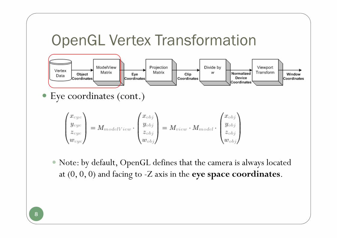
Eye coordinates Using GL_MODELVIEW matrix to transform
objects from “object space” to “eye space”. (multiply GL_MODELVIEW matrix and object coordinates)
GL_MODELVIEW matrix is a combination of Model and View matrices (Mview.Mmodel). Mmodel is to construct objects from “object space/local
space” to “world space”. Mview is to convert objects from “world space” to “eye
space” (camera).
7
OpenGL Vertex Transformation
Eye coordinates (cont.)
Note: by default, OpenGL defines that the camera is always located at (0, 0, 0) and facing to -Z axis in the eye space coordinates.
8
OpenGL Vertex Transformation
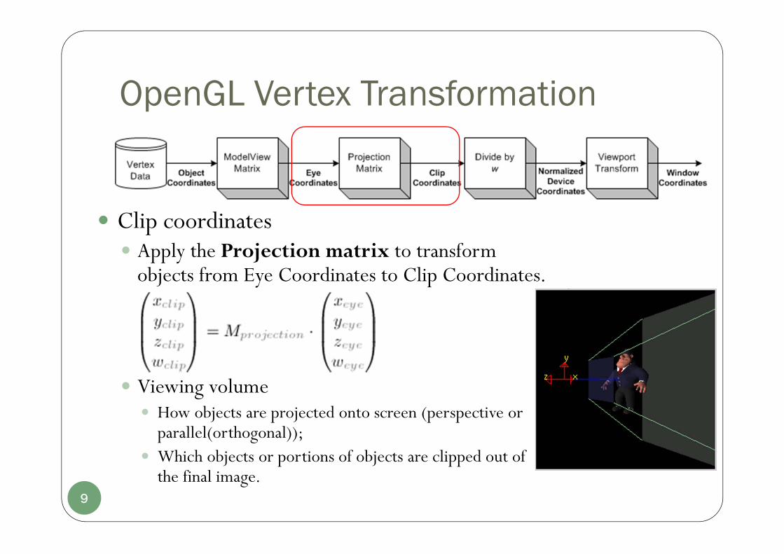
Clip coordinates Apply the Projection matrix to transform
objects from Eye Coordinates to Clip Coordinates.
Viewing volume How objects are projected onto screen (perspective or
parallel(orthogonal)); Which objects or portions of objects are clipped out of
the final image. 9
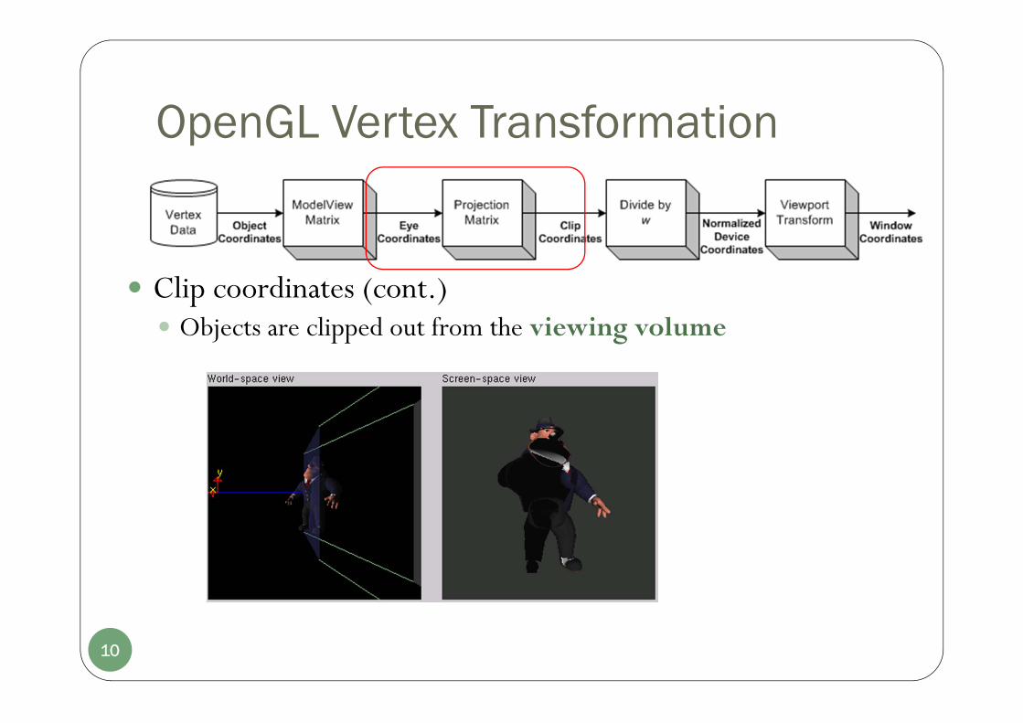
OpenGL Vertex Transformation
Clip coordinates (cont.) Objects are clipped out from the viewing volume
10
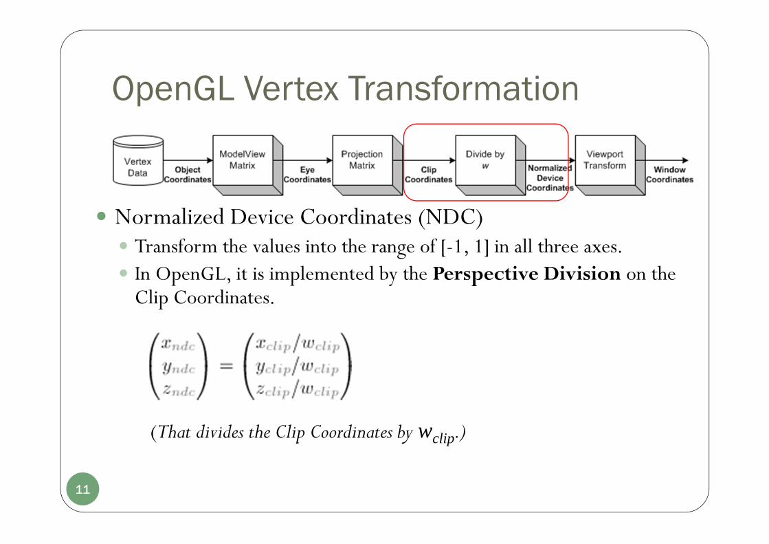
OpenGL Vertex Transformation
Normalized Device Coordinates (NDC) Transform the values into the range of [-1, 1] in all three axes. In OpenGL, it is implemented by the Perspective Division on the
Clip Coordinates.
11
(That divides the Clip Coordinates by wclip.)
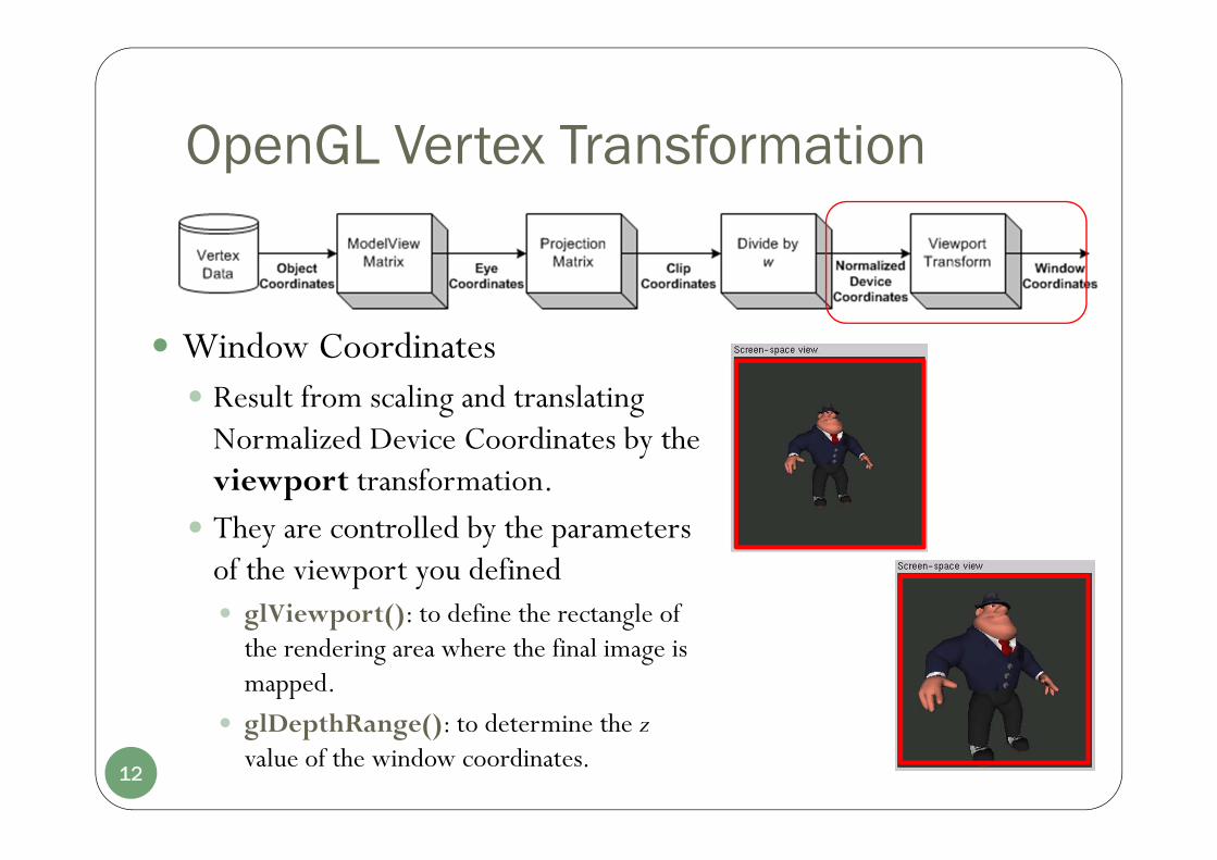
OpenGL Vertex Transformation
Window Coordinates Result from scaling and translating
Normalized Device Coordinates by the viewport transformation.
They are controlled by the parameters of the viewport you defined glViewport(): to define the rectangle of
the rendering area where the final image is mapped.
glDepthRange(): to determine the zvalue of the window coordinates.
12
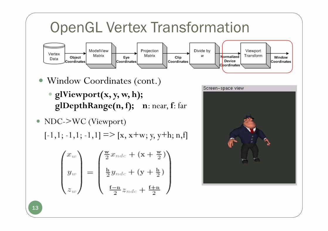
OpenGL Vertex Transformation
Window Coordinates (cont.) glViewport(x, y, w, h);
glDepthRange(n, f); n: near, f: far
13
NDC->WC (Viewport)
[-1,1; -1,1; -1,1] => [x, x+w; y, y+h; n,f]

Chapter 10Three-Dimensional Viewing (OpenGL functions)
Part I.Overview of 3D Viewing Concept
3D Viewing Pipeline vs. OpenGL Pipeline
3D Viewing-Coordinate Parameters Projection Transformations
Viewport Transformation and 3D Screen Coordinates
14
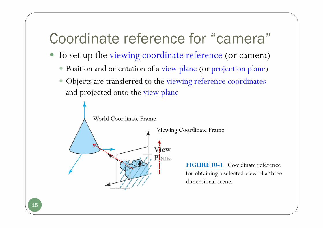
Coordinate reference for “camera” To set up the viewing coordinate reference (or camera) Position and orientation of a view plane (or projection plane) Objects are transferred to the viewing reference coordinates
and projected onto the view plane
FIGURE 10-1 Coordinate reference for obtaining a selected view of a three-dimensional scene.
15
World Coordinate Frame
Viewing Coordinate Frame

3D Viewing-Coordinate Parameters Establish a 3D viewing reference frame Right-handed
16
FIGURE 10-7 A right-handed viewing-coordinate system, with axes xview, yview, zview, relative to a right-handed world-coordinate frame
a. The viewing origin Define the view point or viewing position
(sometimes is referred to as the eye position or the camera position)
b. yview -- view-up vector V Defines yview direction
3D Viewing-Coordinate Parameters Viewing direction and view plane
c. zview: viewing direction Along the zview axis, often in the negative zview direction
d. The view plane (also called projection plane) Perpendicular to zview axis
The orientation of the view plane can be defined by a view-plane normal vector N
The different position of the view-plane along the zview axis
FIGURE 10-8 Orientation of the view plane and view-plane normal vector N
17
FIGURE 10-9 Three possible positions for theview plane along the zview axis
zview
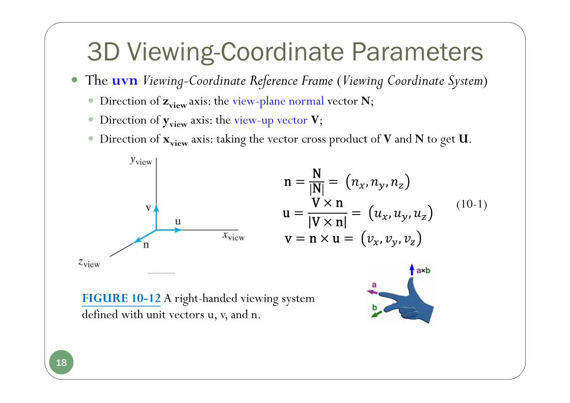
3D Viewing-Coordinate Parameters The uvn Viewing-Coordinate Reference Frame (Viewing Coordinate System)
Direction of zview axis: the view-plane normal vector N;
Direction of yview axis: the view-up vector V;
Direction of xview axis: taking the vector cross product of V and N to get U.
FIGURE 10-12 A right-handed viewing system defined with unit vectors u, v, and n.
(10-1)
18
n NN , ,
uV nV n , ,
v n u , ,

Chapter 10Three-Dimensional Viewing
Part I.Overview of 3D Viewing Concept
3D Viewing Pipeline vs. OpenGL Pipeline
3D Viewing-Coordinate Parameters
Projection Transformations Viewport Transformation and 3D Screen Coordinates
19
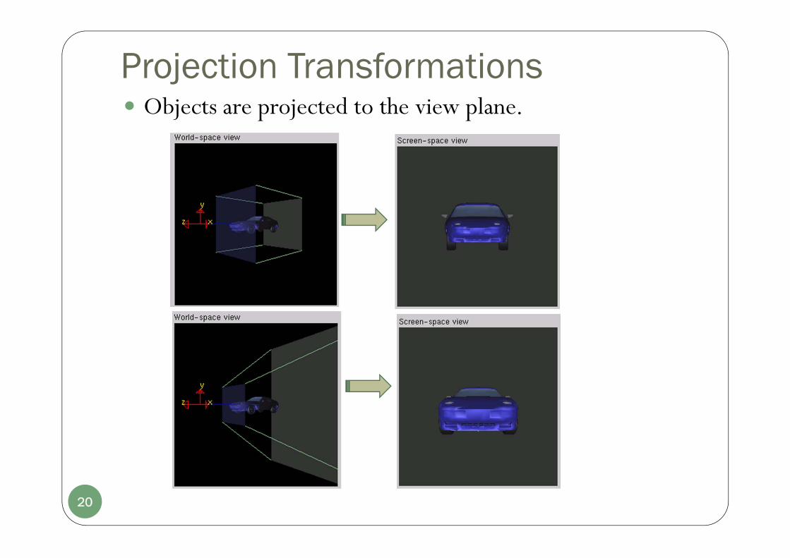
Projection Transformations Objects are projected to the view plane.
20
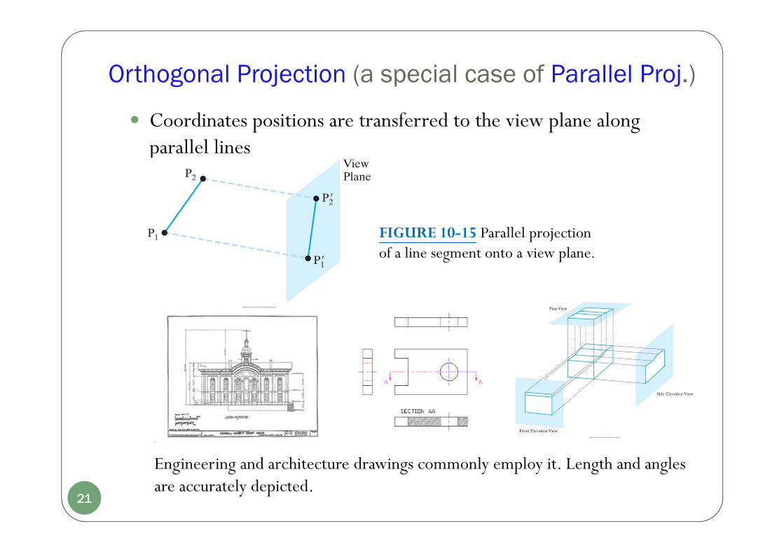
Orthogonal Projection (a special case of Parallel Proj.)
FIGURE 10-15 Parallel projectionof a line segment onto a view plane.
21
Engineering and architecture drawings commonly employ it. Length and angles are accurately depicted.
Coordinates positions are transferred to the view plane along parallel lines
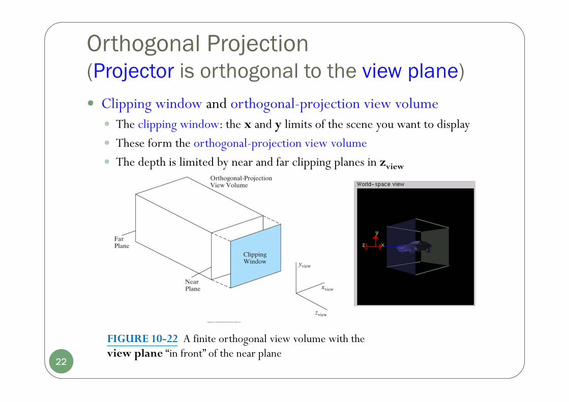
Orthogonal Projection (Projector is orthogonal to the view plane) Clipping window and orthogonal-projection view volume
The clipping window: the x and y limits of the scene you want to display
These form the orthogonal-projection view volume
The depth is limited by near and far clipping planes in zview
FIGURE 10-22 A finite orthogonal view volume with the view plane “in front” of the near plane
22

Normalization Transformation for Orthogonal Projections Map the view volume into a normalized view volume
23
FIGURE 10-24 Normalization transformation from an orthogonal-projection view volume to the symmetric normalization cube within a left-handed reference frame.

Perspective Projections Positions are transferred along lines that converge to a point behind
the view plane.
FIGURE 10-16 Perspective projection of a line segment onto a view plane.
24
FIGURE 10-39A perspective-projection frustum view volume with the view plane “in front” of the near clipping plane
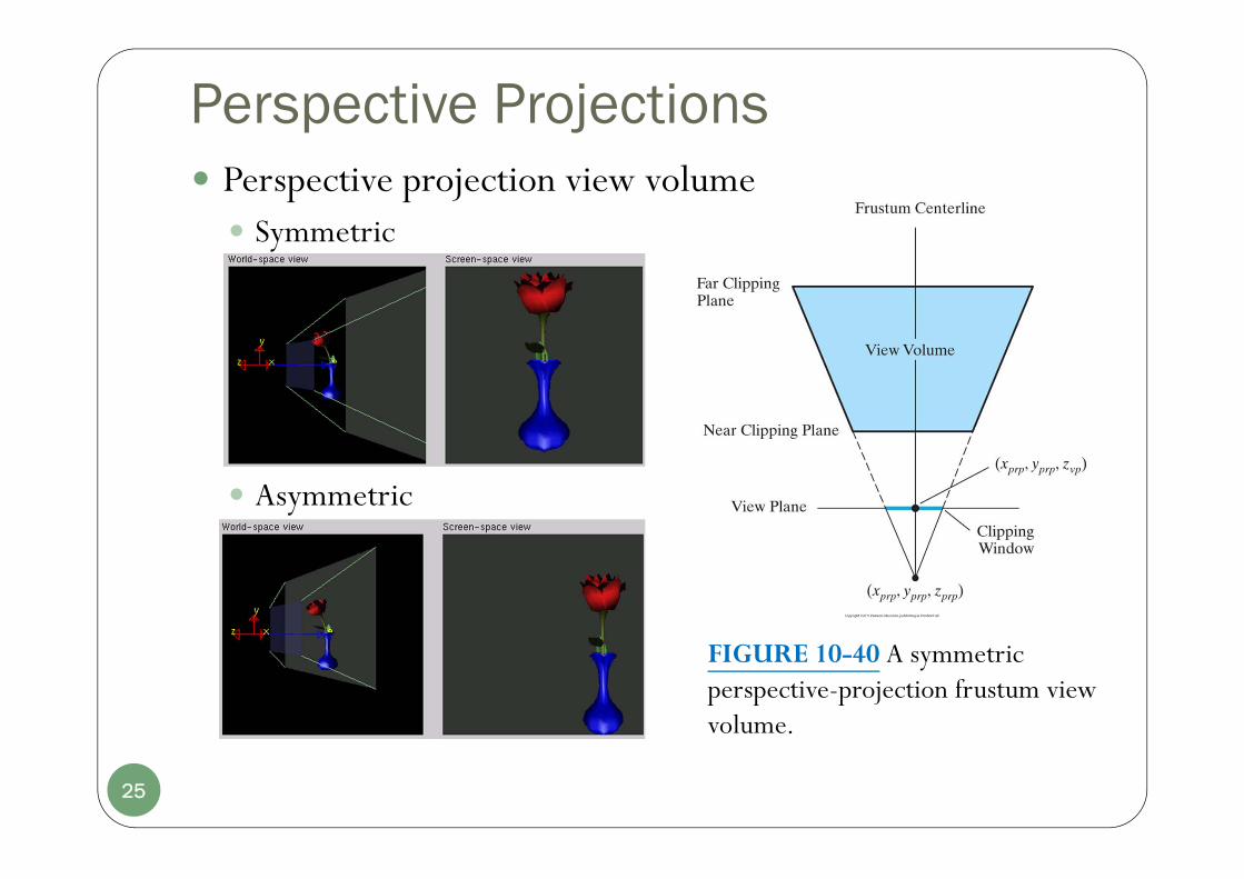
Perspective Projections Perspective projection view volume Symmetric
Asymmetric
25
FIGURE 10-40 A symmetric perspective-projection frustum view volume.

Symmetric Perspective Projections Frustum The corner positions for the clipping window in terms of the
window’s width and height:
26
min max
min min
, 2 2
, 2 2
prp prp
prp prp
width widthxw x xw x
height heightyw y yw y

Another way to specify the symmetric-perspective projection volume Approximate the properties of a camera lens: the field-of-view angle / angle
of view E.g.: a wide-angle lens corresponds to a larger angle of view.
27
Symmetric Perspective Projections Frustum: field-of-view angle/ angle of view
http://www.dyxum.com/columns/photoworld/fundamentals/Field_of_view_Angle_of_view.asp
Focal Length

Another way to specify the symmetric-perspective projection volume In CG, the angle is between the top clipping plane and the bottom clipping plane
FIGURE 10-41 Field-of-view angle θ for a symmetric perspective-projection view volume.
28
Symmetric Perspective Projections Frustum: field-of-view angle/ angle of view

For a given projection reference point and view plane position The height of the clipping window is:
29
Symmetric Perspective Projections Frustum: field-of-view angle
2tan2
2/2
tan
vpprp
vpprp
zzheight
zzheight
How about the width?
Another parameter: the aspect ratio.

Changing field-of-view angle
30
Symmetric Perspective Projections Frustum: field-of-view angle
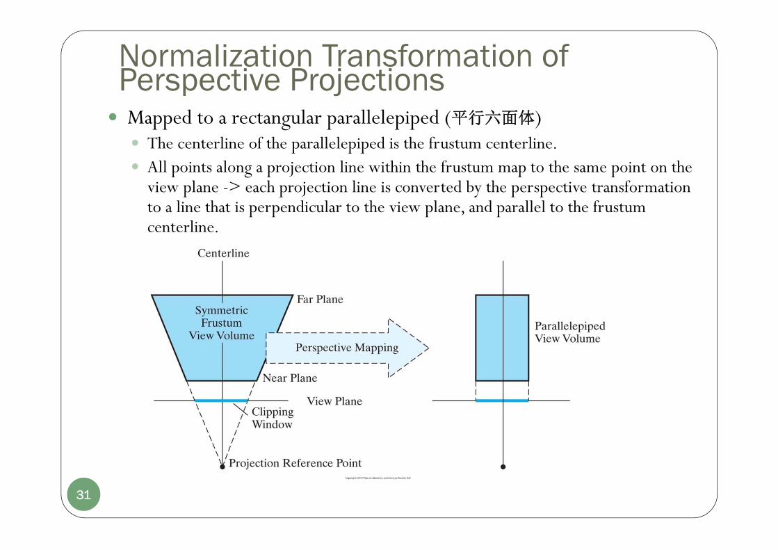
Normalization Transformation of Perspective Projections Mapped to a rectangular parallelepiped (平行六面体)
The centerline of the parallelepiped is the frustum centerline. All points along a projection line within the frustum map to the same point on the
view plane -> each projection line is converted by the perspective transformation to a line that is perpendicular to the view plane, and parallel to the frustum centerline.
31

The rectangular parallelepiped is mapped to a symmetric normalized cube within a left-handed frame.
FIGURE 10-46 Normalization transformation from a transformed perspective projection view volume (rectangular parallelepiped) to the symmetric normalization cube within a left-handed reference frame, with the near clipping plane as the view plane and the projection reference point at the viewing-coordinate origin.
32
Normalization Transformation of Perspective Projections
Chapter 10Three-Dimensional Viewing
Part I.Overview of 3D Viewing Concept
3D Viewing Pipeline vs. OpenGL Pipeline
3D Viewing-Coordinate Parameters
Projection Transformations
Viewport Transformation and 3D Screen Coordinates
33
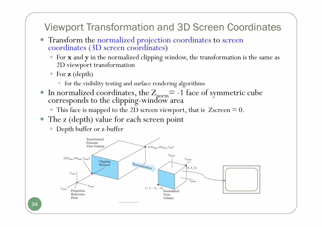
Viewport Transformation and 3D Screen Coordinates Transform the normalized projection coordinates to screen
coordinates (3D screen coordinates) For x and y in the normalized clipping window, the transformation is the same as
2D viewport transformation For z (depth)
for the visibility testing and surface rendering algorithms
In normalized coordinates, the Znorm= -1 face of symmetric cube corresponds to the clipping-window area This face is mapped to the 2D screen viewport, that is Zscreen = 0.
The z (depth) value for each screen point Depth buffer or z-buffer
34
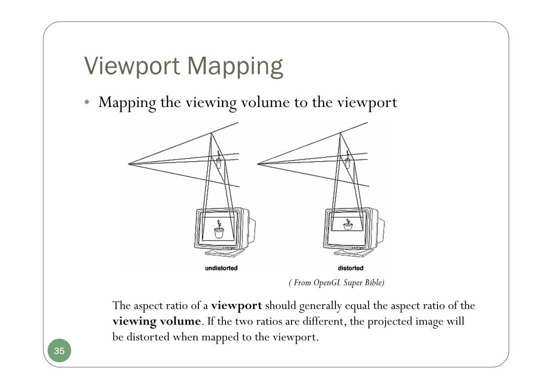
Viewport Mapping• Mapping the viewing volume to the viewport
The aspect ratio of a viewport should generally equal the aspect ratio of the viewing volume. If the two ratios are different, the projected image will be distorted when mapped to the viewport.
( From OpenGL Super Bible)
35
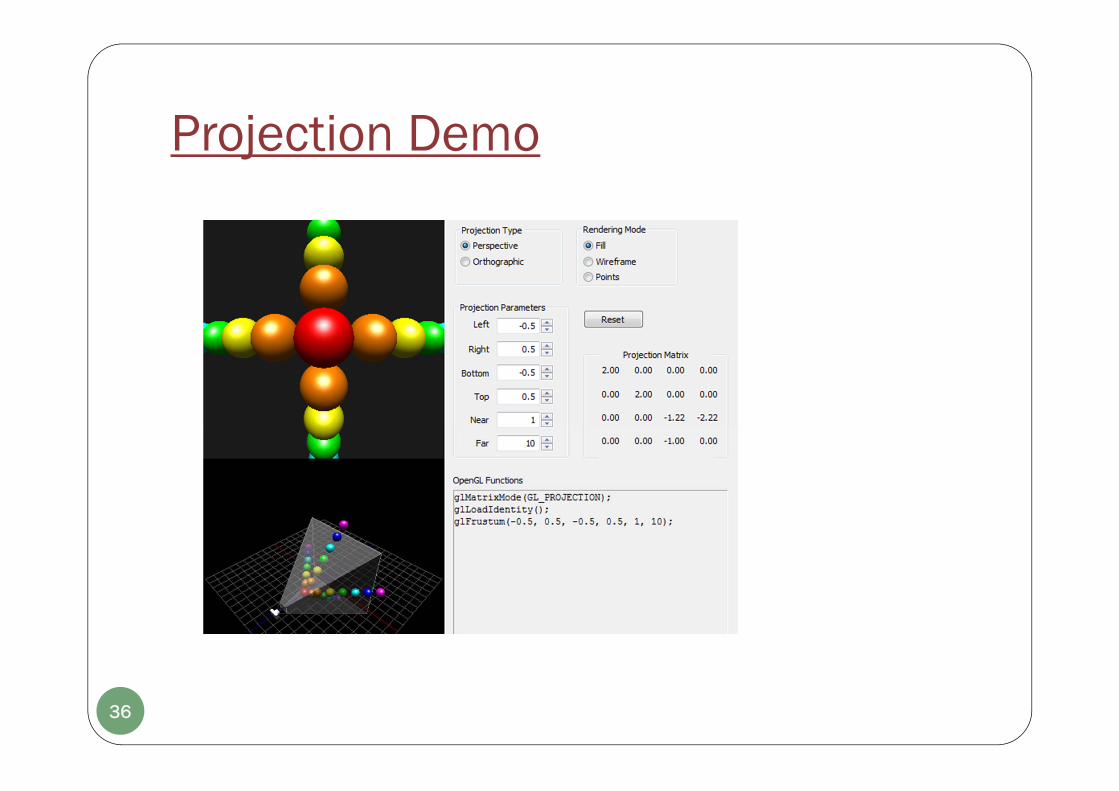
Projection Demo
36

37
Chapter 10Three-Dimensional Viewing
Part II.OpenGL 3D Viewing Functions
OpenGL 3D Projection FunctionsOrthogonal-Projection FunctionPerspective-Projection Functions
OpenGL 3D Viewing Program Example
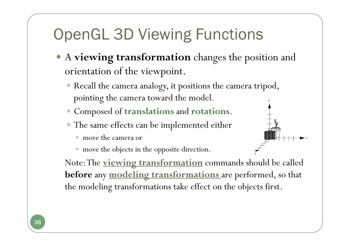
OpenGL 3D Viewing Functions A viewing transformation changes the position and
orientation of the viewpoint. Recall the camera analogy, it positions the camera tripod,
pointing the camera toward the model. Composed of translations and rotations. The same effects can be implemented either move the camera or
move the objects in the opposite direction.
Note: The viewing transformation commands should be called before any modeling transformations are performed, so that the modeling transformations take effect on the objects first.
38

OpenGL 3D Viewing FunctionsMethod a. using glTranslate*() and glRotate*() To emulate the viewpoint movement in a desired way by
translating the objects:
Object and Viewpoint: at the Origin.
(From: the red book)
Move the object away from the viewpoint by translating the object along “-z “ direction:
glTranslatef (0.0, 0.0, -5.0);
39

OpenGL 3D Viewing FunctionsMethod b. using the gluLookAt(eyex, eyey, eyez, atx, aty,
atz, upx, upy, upz) utility routine 3 sets of arguments
The location of the viewpoint,
A reference point where you look at Some position in the center of a scene
View-Up direction
The viewing reference frame defined by the viewing parameters Zview +: N = at-eye;
Yview +: V = up;
Xview +: U = V x N .
The unit axis vectors (uvn) for the viewing reference frame:),,(
),,(||
),,(||
zyx
zyx
zyx
vvvunv
uuuV
nVu
nnnNNn
(10-1)
(z+)
(x+)
(y+)
40
The default OpenGL viewing parameters are:
P0 = (0, 0, 0), Pref = (0, 0, -1), V = (0, 1, 0)
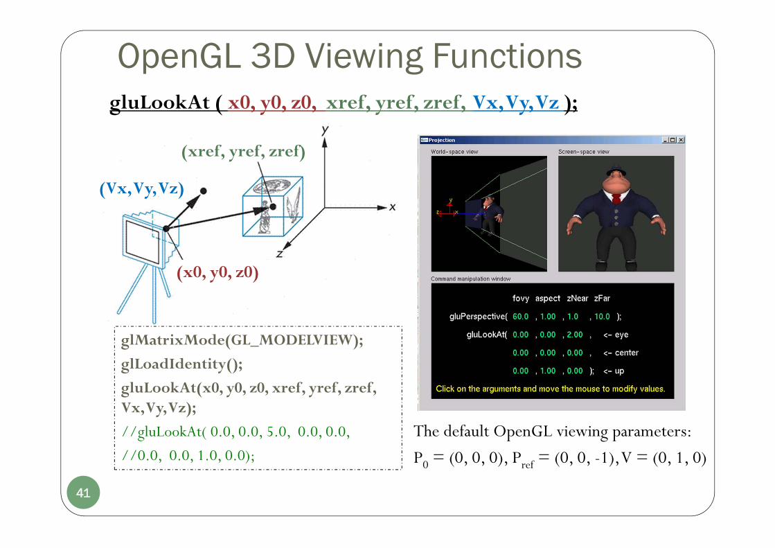
OpenGL 3D Viewing Functions
(x0, y0, z0)
(xref, yref, zref)
(Vx, Vy, Vz)
glMatrixMode(GL_MODELVIEW);
glLoadIdentity();
gluLookAt(x0, y0, z0, xref, yref, zref, Vx, Vy, Vz);
//gluLookAt( 0.0, 0.0, 5.0, 0.0, 0.0,
//0.0, 0.0, 1.0, 0.0);
gluLookAt ( x0, y0, z0, xref, yref, zref, Vx, Vy, Vz );
The default OpenGL viewing parameters:
P0 = (0, 0, 0), Pref = (0, 0, -1), V = (0, 1, 0)
41

Viewing Transformation: HowTo
Method a. Use one or more modeling transformation commands (that is, glTranslate*() and glRotate*()).
Method b. Use the Utility Library routine gluLookAt() to define a line of sight. This routine encapsulates a series of rotation and translation commands.
Method c. Create your own utility routine that encapsulates rotations and translations.
42

OpenGL 3D Projection Functions The purpose of the projection transformation is to
define a viewing volume, which is used in two ways How an object is projected onto the screen; Which objects or portions of objects are clipped out of the final
image.
Before issuing any of projection commands, you should callglMatrixMode(GL_PROJECTION); glLoadIdentity();
so that the commands affect the projection matrix rather than the modelview matrix.
43

OpenGL 3D Projection Functions
OpenGL provides two functions glOrtho(): to produce a orthographic (parallel) projection glFrustum(): to produce a perspective projection (general)
Both functions require 6 parameters to specify six clipping planes: left, right, bottom, top, near and far planes.
GLU library for symmetric perspective-projection gluPerspective(): with only 4 parameters
44

OpenGL Orthogonal-Projection Function
glOrtho ( left, right, bottom, up, near, far );
In OpenGL there is no option for the placement of the view plane:
The near clipping plane = the view plane;
leftright
bottom
up
near
far
45

OpenGL Orthogonal-Projection FunctionglOrtho ( left, right, bottom, up, near, far ); the default one:
glOrtho(-1.0, 1.0, -1.0, 1.0, -1.0, 1.0);
Viewing direction
glOrtho ( left, right, bottom, up, 0, 5.0 ); the far clipping plane: zfar= -5.0. If near or far are negative, the plane is at the positive zview axis (behind the viewing origin)
FIGURE 10-47 Default orthogonal-projection view volume.
2D: gluOrtho2D(left, right, bottom, up);<=> a call to glOrtho() with near = -1.0 and far = 1.0.
46

OpenGL Perspective-Projection Functions General perspective-projection function
glFrustum (left, right, bottom, up, near, far);
left, right, bottom, up: set the size of the clipping window on the near plane.
near, far: the distances from the origin to the near and far clipping planes along the -zview axis. They must be positive. (znear= -near and zfar= -far)
47

OpenGL Perspective-Projection Functions Symmetric perspective-projection function
gluPerspective( theta, aspect, near, far );theta: the field-of-view angle between the top and bottom clipping planes
in the range [ 0°, 180°].aspect: the aspect ratio (width/height) of the clipping window.
near, far: specify the distances from the view point (coordinate origin) to the near and far clipping planes.
Both near and far must be positive values.
znear= -near and zfar= -far refer to the positions of the near and far planes.
theta48

OpenGL 3D Viewing Program Example #include <GL/glut.h>GLint winWidth=600, winHeight=600; // Initial display-window size.GLfloat x0=100.0, y0=50.0, z0=50.0; // Viewing-coordinate origin P0.GLfloat xref=50.0, yref=50.0, zref=0.0; // Look-at point Pref;GLfloatVx=0.0, Vy=1.0, Vz=0.0; // View-up vector/*positive zview axis N = P0 - Pref = (50.0, 0.0, 50.0)
/* Set coordinate limits for the clipping window: */GLfloat xwMin = -40.0, xwMax= 40.0, ywMin = -60.0, ywMax= 60.0;
/* Set positions for near and far clipping planes: */GLfloat dnear=25.0, dfar=125.0;
FIGURE 10-48 Output display generated by the three-dimensional viewing example program.
49

OpenGL 3D Viewing Program Examplevoid init(){
glClearColor(1.0, 1.0, 1.0, 0.0);
glMatrixMode(GL_PROJECTION);glLoadIdentity();glFrustum(xwMin, xwMax, ywMin, ywMax, dnear, dfar);
glMatrixMode(GL_MODELVIEW);glLoadIdentity();gluLookAt(x0, y0, z0, xref, yref, zref, Vx, Vy, Vz);
}
void reshapeFcn(GLsizei newWidth, GLsizei newHeight){
glViewport(0, 0, newWidth, newHeight);winWidth=newWidth;winHeight=newHeight;
}50

void displayFcn(void){
glClear(GL_COLOR_BUFFER_BIT|GL_DEPTH_BUFFER_BIT);
/* Set parameters for a square fill area. */// Set fill color to green.glColor3f(0.0, 1.0, 0.0);glPolygonMode(GL_FRONT, GL_FILL);// Wire-frame back face.glPolygonMode(GL_BACK, GL_LINE);glBegin(GL_QUADS);
glVertex3f(0.0, 0.0, 0.0);
glVertex3f(100.0, 0.0, 0.0);glVertex3f(100.0, 100.0, 0.0);glVertex3f(0.0, 100.0, 0.0);
glEnd();glFlush();
}
OpenGL 3D Viewing Program Example
Foreshortening effectSquare -> trapezoid
51
Summary 3D viewing pipeline and camera analogy
3D viewing transformation and projected transformation viewing coordinates (eye) Orthogonal projection Perspective projection
OpenGL and utility functions glMatrixMode(); GL_MODELVIEW/GL_PROJECTION
gluLookAt(); glOrtho(); glFrustum(); gluPerspective();
52
![Recovering Three-dimensional Shape Around a Corner using ...av21/Documents/2012...tion And Ranging) [1] and two dimensional gated viewing [2] to determine the object distance or to](https://static.fdocuments.net/doc/165x107/5fe1f78fbb6d4365cf32bb7a/recovering-three-dimensional-shape-around-a-corner-using-av21documents2012.jpg)