Chapter 1 - Introduction 1 – Introduction Chapter 1 ... 1.3 Drainage Design Memoranda ... VDOT...
36
VDOT Drainage Manual 1-i Chapter 1 – Introduction Chapter 1 - Introduction TABLE OF CONTENTS CHAPTER 1 - INTRODUCTION ................................................................................................................ 1-1 1.1 Background .................................................................................................................... 1-1 1.2 Overview ......................................................................................................................... 1-2 1.2.1 Purpose ............................................................................................................. 1-2 1.2.2 Manual Layout/Chapter Templates ..................................................................... 1-2 1.3 Drainage Design Memoranda ....................................................................................... 1-4 1.4 References ...................................................................................................................... 1-5 1.5 User Instructions............................................................................................................ 1-6 1.6 Revisions and Updates ................................................................................................. 1-7 1.7 Acknowledgements ....................................................................................................... 1-8 List of Tables Table 1-1. Chapter Template and Contents................................................................................. 1-3 List of Appendices Appendix 1A-1 Definitions and Abbreviations Appendix 1A-2 Symbols
Transcript of Chapter 1 - Introduction 1 – Introduction Chapter 1 ... 1.3 Drainage Design Memoranda ... VDOT...

VDOT Drainage Manual 1-i
Chapter 1 – Introduction
Chapter 1 - Introduction
TABLE OF CONTENTS
CHAPTER 1 - INTRODUCTION ................................................................................................................ 1-1
1.1 Background .................................................................................................................... 1-1
1.2 Overview ......................................................................................................................... 1-2 1.2.1 Purpose ............................................................................................................. 1-2 1.2.2 Manual Layout/Chapter Templates ..................................................................... 1-2
1.3 Drainage Design Memoranda ....................................................................................... 1-4
1.4 References ...................................................................................................................... 1-5
1.5 User Instructions ............................................................................................................ 1-6
1.6 Revisions and Updates ................................................................................................. 1-7
1.7 Acknowledgements ....................................................................................................... 1-8
List of Tables
Table 1-1. Chapter Template and Contents................................................................................. 1-3
List of Appendices
Appendix 1A-1 Definitions and Abbreviations
Appendix 1A-2 Symbols

VDOT Drainage Manual 1-1 of 8
Chapter 1 – Introduction
Chapter 1 - Introduction 1.1 Background
The Virginia Department of Transportation (VDOT) has developed the 2002* VDOT Drainage Manual to provide designers a valuable reference and tool for the drainage design of Virginia’s roadways and to document VDOT’s policies and procedures for standard roadway drainage design.
This edition of the VDOT Drainage Manual constitutes a major technical update and compilation of the existing VDOT Drainage Manual, the AASHTO Model Drainage Manual, and other resources and has been prepared in electronic format to be made available on the Internet at the VDOT website. VDOT’s Hydraulics Section prepared this edition of the manual.
The objectives of the manual are to:
Provide concise technical information for drainage designers Establish VDOT’s policies and procedures for drainage design Provide an educational tool for aspiring drainage designers and instructors Provide in electronic format, available on the World Wide Web for viewing and
downloading Provide guidelines to enhance the quality of drainage design submittals to VDOT
* Rev 1/17

1.2 – Overview
Chapter 1 – Introduction 1-2 of 8
VDOT Drainage Manual
1.2 Overview 1.2.1 Purpose
This manual is intended as an operational handbook for use in hydrologic and hydraulic analysis. D esign concepts, policies and procedures, criteria, and examples are condensed and written for use by the designer. Where appropriate, relevant hydraulic design publications are referenced. While it is essential that the user of this manual is familiar with the methods of analysis and design of highway drainage for VDOT, the text provides detailed instructions and criteria for the development of analysis and design in most cases. A n exception to this rule is the case where another source document expounds upon the method in great detail. In this case, the manual directs the user to the source document or provides a brief synopsis of the subject.
This manual is intended for use in the development of VDOT highway drainage design projects by Department staff, consultants, and Virginia’s municipalities. E ducational organizations may use the manual as instructional text in design application. The manual gives the designer a bas ic working knowledge of hydrology and hy draulics, illustrated with example problems. B asic design elements are included so that the designer can design highway drainage with minimal assistance. However, this manual cannot provide guidance on c omplex hydrologic or hydraulic problems and i s no substitute for experience, formal training, or engineering judgment.
The Department recognizes the difficulty in accurately defining or predicting the dynamic properties of nature. There are numerous methods of analysis available and it is recommended that as many method(s) as may be appropriate be employed in the solution of a problem. F urther, all hydraulic designs must give consideration to economic, aesthetic, and environmental aspects of the given design.
Complete documentation of all analyses is essential and must be perpetually maintained. The rapid development of technology in the fields of hydrology and hydraulics necessitates a periodic review and, if necessary, update of all analyses prior to construction of the facility. A ll analysis completed more than three years before construction must be reviewed prior to construction.
1.2.2 Manual Layout/Chapter Templates
Typical section headings for the main hydraulic chapters are identified in Table 1-1, which indicates the typical contents of the chapter sections.
The Design Concepts section for each technical chapter is generally based on t he AASHTO Model Drainage Manual. A s such, the material is included for theoretical background and may not conform exactly to VDOT methodology, terminology, or nomenclature. When practical, the text is revised to be c onsistent with VDOT methodology and policy.

1.2 – Overview
VDOT Drainage Manual 1-3 of 8
Chapter 1 – Introduction
Table 1-1. Chapter Template and Contents
Sections Contents Introduction Objectives Policy Define Course of Action for VDOT, State, Federal and
Local Policy Design Criteria Specify Standards by which Policy is Carried Out Design Concepts Design Considerations/ Guidelines
Theory and Equations Requirements
Figures Necessary to Support Procedures or Examples Design Procedures & Examples Step-by-Step Procedures
Specific Design Considerations Specific Software Solutions
Figures Necessary to Support Procedures or Examples References Sources of Information / Bibliography Appendices All Figures, Forms and Design Aids Not Necessary to be
in Concepts or Procedures Drainage Design Memoranda
Definitions Checklists
Symbology and Nomenclature

1.3 – Drainage Design Memoranda
Chapter 1 – Introduction 1-4 of 8
VDOT Drainage Manual
1.3 Drainage Design Memoranda Drainage Design Memoranda contain instructional and informational guidance related specifically to drainage design. The instructions and information contained in these memoranda are subject to relatively frequent changes and have therefore intentionally been*
excluded from the main body of text in this manual. These memoranda are all contained in Chapter 15. All Technical Supplements, and Drainage Manual Errata Sheets published prior to issuance of this manual are now included in the manual and are hereby voided.
* Rev 7/14

1.5 – User Instructions
VDOT Drainage Manual 1-5 of 8
Chapter 1 – Introduction
1.4 References
The manual provides references at points where the designer may need more detailed source material. The reference section at the end of each chapter includes these source documents, as well as a listing of those documents, which are recommended additions to the designer’s library of references.
The following documents are an integral part of VDOT roadway and drainage design:
VDOT Reference Documents (all latest editions)
VDOT Road and Bridge Standards, Volume I and II VDOT Road and Bridge Specifications VDOT Instructional and Informational Memoranda VDOT Road Design Manual Virginia Stormwater Management Regulations (9VAC25-870) Virginia Erosion and Sediment Control Regulations (9VAC25-840) Virginia Erosion and Sediment Control Handbook Virginia Stormwater Management Handbook, Volumes I and II VDOT Survey Instruction Manual
Compliance with the following applicable laws and agencies’ regulations and policies are required:
Virginia Department of Transportation Virginia Stormwater Management Regulations Virginia Erosion and Sediment Control Regulations State Drainage Law FHWA Federal Aid Policy Guide Federal Emergency Management Agency Environmental Protection Agency Regulation National Pollution Discharge Elimination System (NPDES) Department of Environmental Quality
Rev 7/14

1.5 – User Instructions
Chapter 1 – Introduction 1-6 of 8
VDOT Drainage Manual
1.5 User Instructions This manual is divided into 16
The downloaded electronic version of the Drainage Manual and its revisions will be considered the official reference document in agreements with consultants. The manual can be downloaded from VDOT’s website at the following location:
chapters, each dealing with a major category of hydrologic or hydraulic analysis. Each chapter is further divided according to specific elements of the subject. Departmental policy and design criteria are presented in each chapter as they relate to the specific subject matter.
http://www.virginiadot.org/business/locdes/hydra-drainage-manual.asp. The authors of this manual have strived to maintain the accuracy and reliability of the information and procedures presented herein. The execution of an engineering design; however, involves the judgment of the designer, and only he or she can ascertain whether a technique or item of information can be applied to a given situation. Therefore, neither the Department nor any contributor accepts responsibility for any real or alleged error, loss, damage, or injury resulting from use of the material contained herein.
References to specific computer programs, AASHTO guidelines, manual, and regulations are included in this manual. It is expected that the designer will be knowledgeable in the use of the referenced items. This manual cannot incorporate computer program user manuals or remain current with these programs and the latest drainage-related Federal regulations. The designers should keep themselves up-to-date by contacting either their local, State, or Federal hydrology/hydraulic departments.
This manual is published in U. S. Customary (English) units. In most cases all units, equations, tables, and figures are given in English units. In a few instances, some existing metric information was not converted to English units. The metric units are given so that the material could still be included in the manual. In most cases, computer software is available that allows the use of English units that can be used to obtain the required information.
Information in this Manual may be supplemented and/or revised by drainage related Location and Design Instructional and Informational Memorandums (IIM’s). Information in these IIM’s shall supersede that noted in this Manual unless otherwise approved by the State Hydraulics and Utilities Engineer. Where language in various sections of this Manual conflict, the more stringent language shall dictate unless otherwise approved by the State Hydraulics and Utilities Engineer.
Rev 7/14

1.6 – Revisions and Updates
VDOT Drainage Manual 1-7 of 8
Chapter 1 – Introduction
1.6 Revisions and Updates VDOT plans to issue updates and revisions to this manual which will be found at the VDOT website. Updates and revisions would normally be anticipated no more than twice a year. Users of the manual should review the VDOT website periodically and prior to beginning design or preparing a plan submittal, to determine the date of the most recent updates. Users that cannot access the information on the Internet may phone the VDOT Hydraulics Section in the nearest district office or Central Office in Richmond, Virginia. When revisions are available, the user will be notified via an Errata Sheet file on the VDOT website at the location where the manual may be viewed and/or downloaded. These files also briefly describe each revision. All revised material (where possible) will be shaded so the user will be able to recognize it as having been changed. The shaded material within any given chapter will remain shaded until the next revision, at which time all previous shading in that chapter will be removed.

1.7 - Acknowledgements
Chapter 1 – Introduction 1-8 of 8
VDOT Drainage Manual
1.7 Acknowledgements
The Department gratefully acknowledges the following for their contribution towards the preparation of this Manual:
American Association of State Highway and Transportation Officials (AASHTO Drainage Manual, Highway Drainage Guidelines, and other publications) - Executive Committee - Hydrology and Hydraulics Technical Committee
Federal Highway Administration Federal Emergency Management Agency United States Geological Survey United States Army Corps of Engineers Virginia Department of Transportation –
- Mr. Jeff Bragdon, P.E., State Hydraulics and Utilities Engineer - Mr. Chris Swanson, P.E., State MS4/Stormwater Management Engineer - Mr. Roy Mills, Former State Hydraulics Engineer and Member AASHTO
Hydrology and Hydraulics Technical Committee Virginia Department of Conservation and Recreation – Division of Soil & Water
Conservation Virginia Department of Environmental Quality Materials furnished by other state and federal agencies Research publications and materials furnished by the private sector Photo on cover courtesy of Virginia Department of Game and Inland Fisheries.
Photographed by Mr. Dwight Dyke. Big Tumbling Creek at the Clinch Mountain Wildlife Management Area.
The Department’s Hydraulic Section wishes to express its appreciation to all contributors who assisted in the development of this manual.
Rev 1/17

Chapter 1 – Introduction
Page 1 of 14
Appendix 1A-1 Abbreviations and Definitions Abbreviations: AASHTO American Association of State Highway and Transportation
Officials BDF Basin Development Factor BLM Bureau of Land Management BMP Best Management Practice* BRI-STARS Bridge Stream Tube Model for Sediment Routing Alluvial
River Simulation BSD Better Site Design CBPA Chesapeake Bay Preservation Area CEM Coastal Engineering Manual CF Channel Flow CFR Code of Federal Regulations DCR Department of Conservation and Recreation DDM Drainage Design Memorandum DEQ Department of Environmental Quality EO Executive Orders EPA Environmental Protection Agency ESC Erosion and Sediment Control FEMA Federal Emergency Management Agency FHWA Federal Highway Administration FWPCA Federal Water Pollution Control Act FWS Fish and Wildlife Service HDS Hydraulic Design Series HEC Hydraulic Engineering Circular HIRE Highways in the River Environment HUC Hydrologic Unit Code HW Headwater HYG Hydrograph I&IM or IIM Instructional and Informational Memorandum IDF Intensity Duration Frequency LDP Land Development Project LID Low Impact Development LTEC Least Total Expected Cost MHW Mean High Water MHHW Mean Higher High Water MLW Mean Low Water MLLW Mean Lower Low Water MS Minimum Standard MS4 Municipal Separate Storm Sewer System MSL Mean Sea Level MTL Mean Tide Level
* Rev 9/09

Chapter 1 – Introduction
Page 2 of 14
MTR Mean Tide Range NAS National Academy of Sciences NAVD North America Vertical Datum NEH National Engineering Handbook NEPA National Environmental Protection Agency NFIA National Flood Insurance Act NFIP National Flood Insurance Program NGS National Geodetic Survey NGVD National Geodetic Vertical Datum NHS National Highway System NOAA National Oceanic and Atmospheric Administration NPDES National Pollutant Discharge Elimination System NRCS National Resource Conservation Service (formally known as
the Soil Conservation Service or SCS) NTIS National Technical Information Service OLF Overland Flow PAC Pre-Advertisement Conference P2 Pollution Prevention R&B Road and Bridge RDM Road Design Manual RFP Request for Proposal R/W Right-of-Way SCS Soil Conservation Service (former name of the National
Resource Conservation Service) SPM Shore Protection Manual SWCB Soil and Water Conservation Board SWL Still Water Level SWM Stormwater Management SWMR Stormwater Management Regulations SWPPP Stormwater Pollution Prevention Plan SYIP Six-Year Improvement Plan TMDL Total Maximum Daily Load TR Technical Release TVA Tennessee Valley Authority TW Tailwater USBR United States Bureau of Reclamation USCOE/USACE United States Corps of Engineers USGS United States Geological Survey VAC Virginia Administrative Code VDOT Virginia Department of Transportation or the “Department” VESC Virginia Erosion and Sediment Control VESCH Virginia Erosion and Sediment Control Handbook VESCR Virginia Erosion and Sediment Control Regulations VPDES Virginia Pollutant Discharge Elimination System VRRM Virginia Runoff Reduction Methodology VSMP Virginia Stormwater Management Program

Chapter 1 – Introduction
Page 3 of 14
VSMR Virginia Stormwater Management Regulations VSWCB Virginia Soil and Water Conservation Board WES Waterways Experiment Station WQV Water Quality Volume WRC Water Resources Council

Chapter 1 – Introduction
Page 4 of 14
Definitions: Adequate Channel (1) A natural channel, which is capable of
conveying the runoff from a 2-year storm without overtopping its banks or eroding after development of the site in question, (2) A previously constructed manmade channel shall be capable of conveying the runoff from a 10-year storm without overtopping its banks, and bed or bank erosion shall not occur due to a 2-year storm, (3) Pipes and storm sewer systems shall contain the 10-year storm.
Average Land Cover Condition A measure (in percent) of the average amount
of impervious area within a watershed. Backshore The backshore is the area of the coastal zone
that extends from the limit of high tides and storm waves to the base of a cliff or beach ridge.
Barrier Beach A bar essentially parallel to the shore, which has been built up so that its crest rises above the normal high water level.
Bridges (1) Structures that transport traffic over
waterways or other obstructions, (2) Part of a stream crossing system that includes the approach roadway over the floodplain, relief openings, and the bridge structure, (3) Structures with a centerline span of 20 feet or more; however, structures designed hydraulically as bridges are considered bridges, regardless of length.
CBR Tests The California Bearing Ratio (CBR) test
consists of measuring the relative load required to cause a standard (3 square inches) plunger to penetrate a water-saturated soil specimen at a specific depth.
Channel A natural or manmade waterway (includes
culverts and storm sewer systems). Check Storm The use of a less frequent event, such as a 50-
year storm, to assess hazards at critical

Chapter 1 – Introduction
Page 5 of 14
locations, where water can pond to appreciable depths.
Code of Federal Regulations Codifies and publishes at least annually
Federal regulations currently in force. The CFR is kept up to date by individual issues of the Federal Register. The two publications must be used together to determine the latest version of any given rule.
Common Enemy Doctrine Common law rule recognized by some states,
pertaining to the disposal of surplus or excess surface waters, which holds that such waters are a “common enemy”; therefore, the land owner has the right to protect his lands from such waters coming from higher lands. Under this rule, surface waters are regarded as a common enemy, which each landowner may fight as he deems best and without regard to the harm that may be caused to others.
Common Laws The body of principles which developed from
immemorial usage and custom and which receives judicial recognition and sanction through repeated application.
Critical Depth Critical depth is the depth at which the specific
energy of a given flow rate is at a minimum. For a given discharge and cross-section geometry there is only one critical depth.
Culvert (1) A structure which is usually designed
hydraulically to take advantage of submergence to increase hydraulic capacity, (2) A structure used to convey surface runoff through embankments, (3) A structure, as distinguished from bridges, which is usually covered with embankment and is composed of structural material around the entire perimeter, although some are supported on spread footings with the streambed serving as the bottom of the culvert, (4) A structure which is traditionally 20 feet or less in centerline length between extreme ends of openings for multiple boxes; however, a structure designed

Chapter 1 – Introduction
Page 6 of 14
hydraulically as a culvert is treated as a culvert, regardless of length.
Deep-water Wave A wave in which the depth of water is greater
than one-half the wavelength. Department The Virginia Department of Transportation. Detention Basins A basin or reservoir incorporated into the
watershed, whereby runoff is temporarily stored, thus attenuating the peak of the runoff hydrograph. A stormwater management facility that impounds runoff and temporarily impounds runoff and discharges it through a hydraulic outlet structure to a downstream conveyance structure.
Discharge Point The location at which stormwater and/or a
pollutant leaves the project area. Downcast The direction of predominant movement of
littoral currents and transport. Embayment An indentation in a shoreline forming an open
bay. English Rule Based on the doctrine of absolute ownership of
water beneath the property by the landowner. The English Rule is analogous to the common enemy rule in surface water law.
Eutrophication The process of over-enrichment of water
bodies by nutrients often typified by the presence of algal blooms.
Executive Orders Federal laws that are issued by the President
of the United States. Federal Register A daily publication of the Federal Government
making federal regulations, legal notices, Presidential Proclamations, Executive Orders, etc., known to the public as they are proposed and subsequently issued.
Fetch The length of unobstructed open sea surface
across which the wind can generate waves.

Chapter 1 – Introduction
Page 7 of 14
Flood Insurance Study Established the original floodway. Flow Type The USGS has established seven culvert flow
types which assist in determining the flow conditions at a particular culvert site.
Foreshore The foreshore is the area of the coastal zone
that extends from the low-tide level to the limit of high tides and storm-wave effects.
Free Outlet A free outlet has a tailwater equal to or lower
than critical depth. For culverts having free outlets, lowering of the tailwater has no effect on the discharge or the backwater profile upstream of the tailwater.
Headland A headland is the seaward most projection of
land from the shoreline. Because headlands project out into waves and currents, headlands are usually subjected to greater erosion forces. Headlands may be the remnants of submerged ridgelines or be composed or erosion resistant materials.
HUC6 A watershed unit established in the most
recent version of Virginia's 6th Order National Watershed Boundary Dataset.
Hydraulic Grade Line The elevation to which the water can be
expected to rise within a storm drain (pressure head + elevation head)
Impervious Surface or Cover A surface composed of any material that
significantly impedes or prevents natural infiltration of water into soil. Impervious surfaces include, but are not limited to, roofs, buildings, streets, parking areas, and any concrete, asphalt, or compacted gravel surface.
Impervious Area The area (square feet or acres) of the site
composed of an impervious surface. Improved Inlet An improved inlet has an entrance geometry,
which contracts the flow as it enters the barrel thus increasing the capacity of culvert. These

Chapter 1 – Introduction
Page 8 of 14
inlets are referred to as either side- or slope-tapered (walls or walls and bottom tapered).
Karst Topography Irregular topography characterized by
sinkholes, stream-less valleys and streams that disappear into the underground, all developed by the action of surface and underground water in soluble rock such as limestone.
Lakeshore The strip of land from a lake shoreline inland to
the first major change in terrain features. Except for tidal effects, large lakes and reservoirs of 100 mi2 or more in area, have shores that require many of the same type considerations as ocean bays and estuaries. Analogous to coastal zone tides, some lakeshores are subject to significant changes in water surface elevation due to operation practices.
Land-Disturbing Activity or Land Disturbance A manmade change to the land surface that
potentially changes its runoff characteristics including any associated clearing, grading or excavation.
Linear Development Projects Those land-disturbing activities linear in nature
such as, but not limited to, highway construction/ maintenance projects/ activities, construction/ maintenance of stormwater channels and stream restoration projects.
Longshore Currents or sediment transport that move
parallel to the shoreline. Managed Turf Means portions of roadway rights-of-way that
are pervious and do not meet the definition of open space.
Manmade Channel A machine/hand-defined landform (ie.
roadside* ditch, EC-2/EC-3/paved/concrete/ riprap lining, and outfall important) or manufactured conveyance structure (ie. storm sewer pipe, culvert, inlet) located in VDOT R/W
* Rev 5/17
Chapter 1 – Introduction
Page 9 of 14
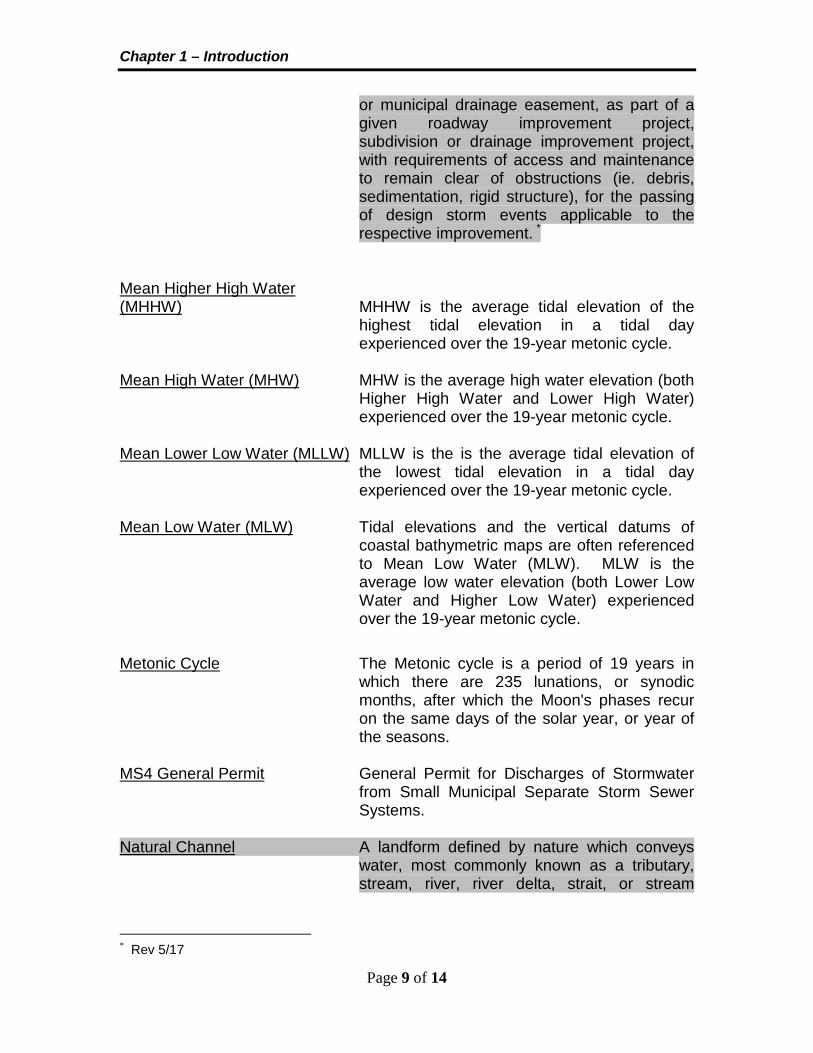
or municipal drainage easement, as part of a given roadway improvement project, subdivision or drainage improvement project, with requirements of access and maintenance to remain clear of obstructions (ie. debris, sedimentation, rigid structure), for the passing of design storm events applicable to the respective improvement. *
Mean Higher High Water (MHHW) MHHW is the average tidal elevation of the
highest tidal elevation in a tidal day experienced over the 19-year metonic cycle.
Mean High Water (MHW) MHW is the average high water elevation (both
Higher High Water and Lower High Water) experienced over the 19-year metonic cycle.
Mean Lower Low Water (MLLW) MLLW is the is the average tidal elevation of
the lowest tidal elevation in a tidal day experienced over the 19-year metonic cycle.
Mean Low Water (MLW) Tidal elevations and the vertical datums of
coastal bathymetric maps are often referenced to Mean Low Water (MLW). MLW is the average low water elevation (both Lower Low Water and Higher Low Water) experienced over the 19-year metonic cycle.
Metonic Cycle The Metonic cycle is a period of 19 years in
which there are 235 lunations, or synodic months, after which the Moon's phases recur on the same days of the solar year, or year of the seasons.
MS4 General Permit General Permit for Discharges of Stormwater
from Small Municipal Separate Storm Sewer Systems.
Natural Channel A landform defined by nature which conveys
water, most commonly known as a tributary, stream, river, river delta, strait, or stream
* Rev 5/17

Chapter 1 – Introduction
Page 10 of 14
restoration. (A manmade channel is not to be considered a natural channel). *
Non-Linear Projects Those land-disturbing activities not considered
linear in nature such as, but not limited to, parking lots, rest areas and District/Residency/ Area Headquarter complexes.
Normal Flow Normal flow occurs in a channel reach when
the discharge, velocity and depth of flow do not change throughout the reach. The water surface and channel bottom will be parallel. This type of flow will exist in a culvert operating on a constant slope provided the culvert is sufficiently long.
Offsite Areas located outside of the VDOT right of
way, easement or property boundary. Onsite Areas located inside of VDOT right of way,
easement or property boundary. Open Space Means portions of roadway rights-of-way and
permanent easements associated with a land-disturbing activity that, following construction, have either not been compacted by the activity; have had soil restoration; or have placed engineered soil mix, and will not be actively maintained. Typically, actively maintained means mowed more than four (4) times a year or fertilized. Surfaced area of stormwater facilities, with the exception of wet ponds, shall qualify as open space.
Outfall The location where concentrated stormwater
leaves the project area. Pre-development Those conditions that exist prior to
commencement of the proposed land-disturbing activity/project.
Pre-development Impervious Area The amount of impervious area within the site
prior to commencement of the proposed land-disturbing activity/project.
* Rev 5/17
Chapter 1 – Introduction
Page 11 of 14
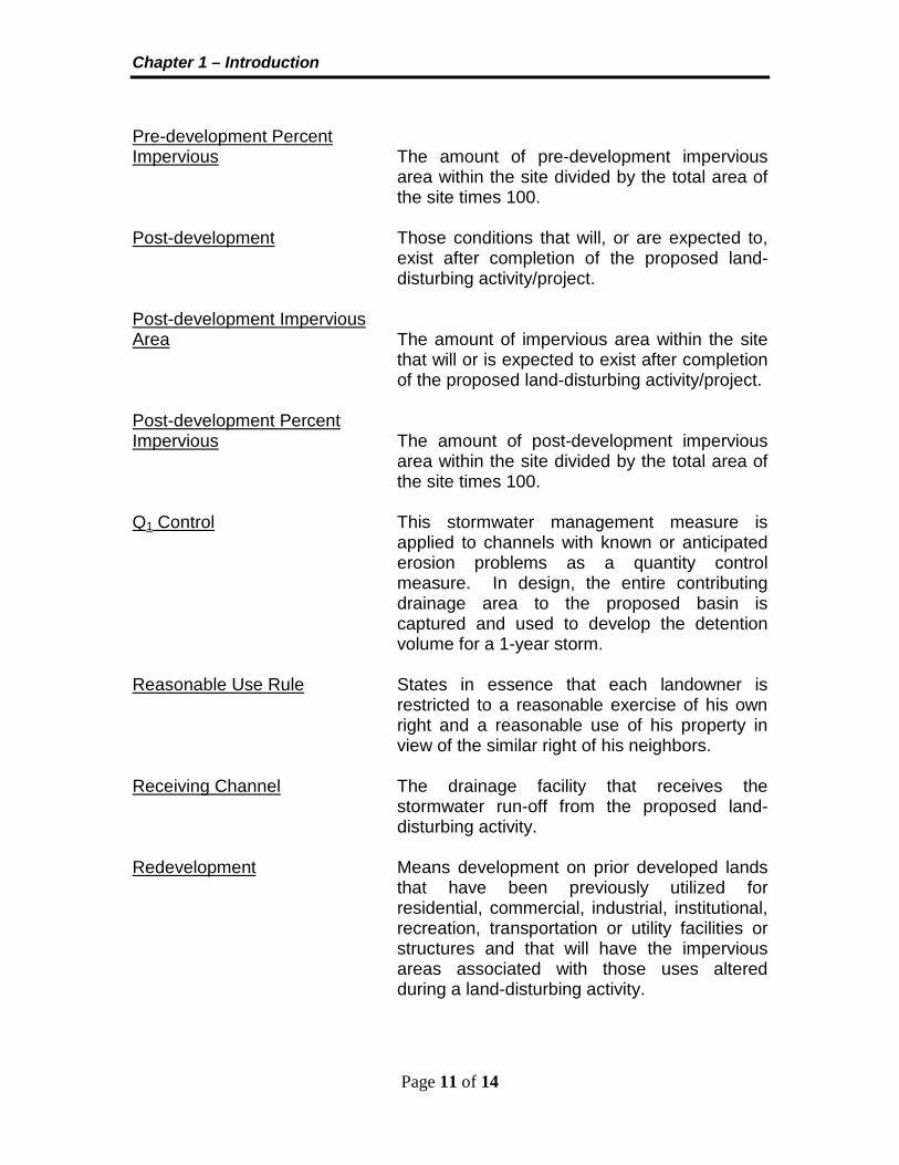
Pre-development Percent Impervious The amount of pre-development impervious
area within the site divided by the total area of the site times 100.
Post-development Those conditions that will, or are expected to,
exist after completion of the proposed land-disturbing activity/project.
Post-development Impervious Area The amount of impervious area within the site
that will or is expected to exist after completion of the proposed land-disturbing activity/project.
Post-development Percent Impervious The amount of post-development impervious
area within the site divided by the total area of the site times 100.
Q1 Control This stormwater management measure is
applied to channels with known or anticipated erosion problems as a quantity control measure. In design, the entire contributing drainage area to the proposed basin is captured and used to develop the detention volume for a 1-year storm.
Reasonable Use Rule States in essence that each landowner is
restricted to a reasonable exercise of his own right and a reasonable use of his property in view of the similar right of his neighbors.
Receiving Channel The drainage facility that receives the
stormwater run-off from the proposed land-disturbing activity.
Redevelopment Means development on prior developed lands
that have been previously utilized for residential, commercial, industrial, institutional, recreation, transportation or utility facilities or structures and that will have the impervious areas associated with those uses altered during a land-disturbing activity.

Chapter 1 – Introduction
Page 12 of 14
Regulated Land Disturbance Activities Those activities that disturb one (1) acre or
greater except in those areas designated as a Chesapeake Bay Preservation Area in which case the land disturbance threshold is 2500 square feet or greater (unless the activity is specifically exempted by the VSMP Law and/or Regulations).
Regulated Site The area within the project limits used to
determine water quality requirements. Retention Basins A basin or reservoir wherein water is stored for
regulating a flood. It does not have an uncontrolled outlet. The stored water is disposed by such means as infiltration, injection (or dry) wells, or by release to the downstream drainage system after the storm event. The release may be through a gate controlled gravity system or by pumping.`
Riparian Doctrine A doctrine that holds that the property owner
adjacent to a surface water body has first right to withdraw and use the water. This doctrine may be set aside by a state’s statutory law that holds that all surface waters are the property of the state.
Roadway Section The traveled way and associated shoulders,
ditches, sidewalks, multi-use/shared use paths, back (cut) slopes and fore (fill) slopes
Seiche A seiche is an oscillatory wave generated by
an impulse that disturbs the local water level equilibrium. The impulse may be a heavy rainfall, vessel passage, tsunami, flood discharge from a river, or a storm surge. Much like dropping a stone in to a tank of water, seiche waves oscillate back and forth, gradually diminishing in magnitude.
Site The area of proposed land disturbance (e.g.,
the construction limits) plus any R/W acquired in support of the proposed land disturbance activity/project. Any support areas within existing or proposed VDOT R/W associated

Chapter 1 – Introduction
Page 13 of 14
with the proposed land disturbance activity/project and identified in the pre-construction SWPPP for the proposed land disturbance activity/project shall also be considered a part of the site. Permanent easements and/or other property acquired through the R/W acquisition process in conjunction with the proposed land disturbance activity/project may be considered a part of the site and utilized in the determination of the post-development water quality requirements provided such property will remain under the ownership/control of the VDOT and providing such property is so identified/designated on the proposed land disturbance activity/project plans and is legally encumbered for the purpose of stormwater management.
Slope A steep slope occurs where critical depth is
greater than normal depth. A mild slope occurs where critical depth is less than normal depth.
Spread The width of flow measured laterally from the
flowline. With a curbed only section of roadway, the flowline is formed by the intersection of the pavement to the curb. With a curb and gutter section, it is the intersection of the gutter pan and the curb.
Statutory Laws Enacted by legislatures to enlarge, modify,
clarify, or change the common law applicable to particular drainage conditions. This type of law is derived from constitutions, statutes, ordinances, and codes.
Still-water Level (SWL) SWL is used to refer to the imaginary elevation
of water if all wave and wind action were to cease. SWL is used to define limits of coastal inundation during storm surges. Actual water levels are higher due to waves.
Storm Drain A storm drain system is a drainage system
installed to carry stormwater runoff, consisting of two or more pipes in a series connected by one or more drop inlets. An exception to this
Chapter 1 – Introduction
Page 14 of 14
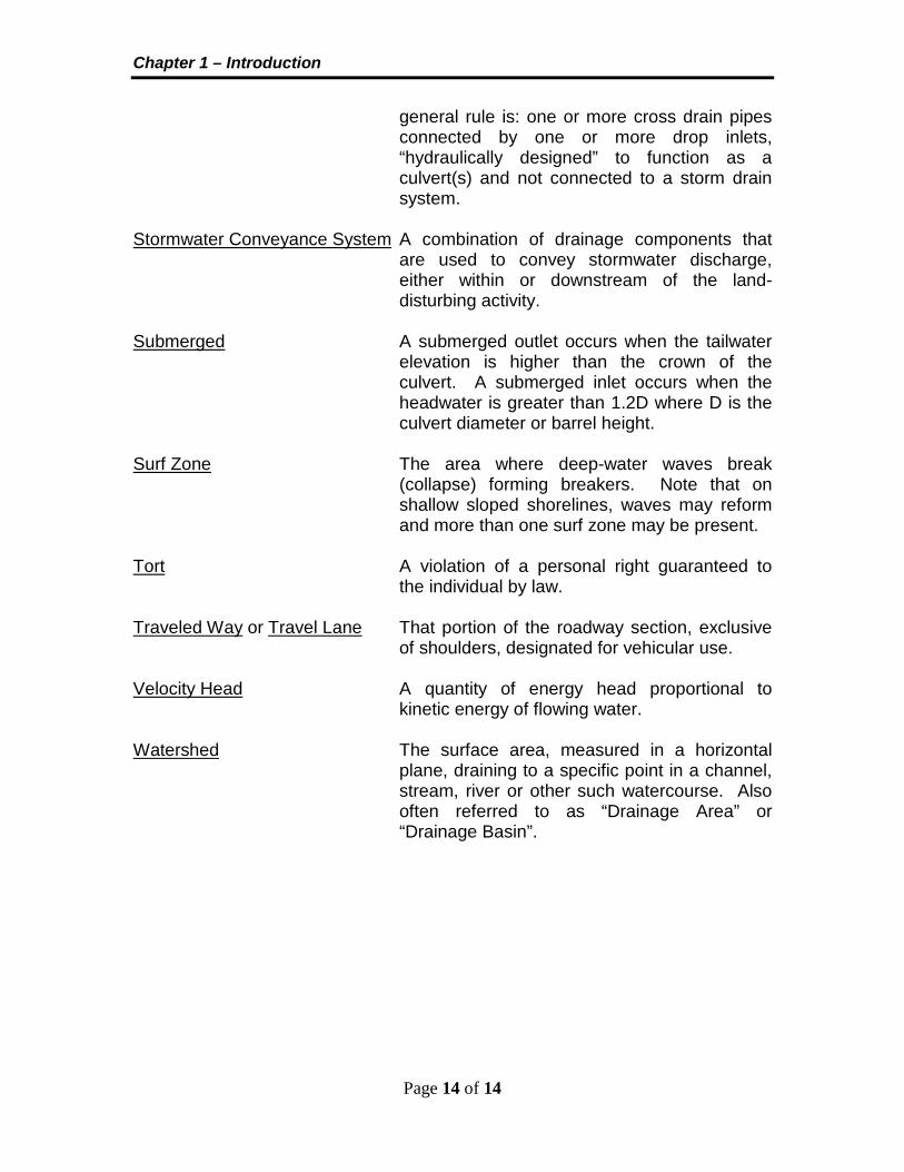
general rule is: one or more cross drain pipes connected by one or more drop inlets, “hydraulically designed” to function as a culvert(s) and not connected to a storm drain system.
Stormwater Conveyance System A combination of drainage components that
are used to convey stormwater discharge, either within or downstream of the land-disturbing activity.
Submerged A submerged outlet occurs when the tailwater
elevation is higher than the crown of the culvert. A submerged inlet occurs when the headwater is greater than 1.2D where D is the culvert diameter or barrel height.
Surf Zone The area where deep-water waves break
(collapse) forming breakers. Note that on shallow sloped shorelines, waves may reform and more than one surf zone may be present.
Tort A violation of a personal right guaranteed to
the individual by law. Traveled Way or Travel Lane That portion of the roadway section, exclusive
of shoulders, designated for vehicular use. Velocity Head A quantity of energy head proportional to
kinetic energy of flowing water. Watershed The surface area, measured in a horizontal
plane, draining to a specific point in a channel, stream, river or other such watercourse. Also often referred to as “Drainage Area” or “Drainage Basin”.

Chapter 1 – Introduction
Appendix 1A-2 Symbols
1 of 13 VDOT Drainage Manual
Symbol Definition Units
A Drainage Area
acres, mi2
A Cross-sectional area of flow; Clear opening area of curb inlet or grate; Cross-sectional or surface area
ft2
a Rainfall regression constant
-
a Depth of depression
feet
B Barrel or box width
inches, feet
b Manhole diameter or width
feet
b Rainfall regression constant
-
b1 Urban Regression Method exponent
-
b2 Urban Regression Method exponent
-
b3 Urban Regression Method exponent
-
b4 Urban Regression Method exponent
-
b5 Urban Regression Method exponent
-
b6 Urban Regression Method exponent
-
b7 Urban Regression Method exponent
-
BDF Basin Development Factor
%

Chapter 1 – Introduction
Appendix 1A-2 Symbols
2 of 13 VDOT Drainage Manual
C Runoff coefficient; Urban Regression Method constant; Stone size correction factor; Broad-crested weir coefficient or orifice coefficient
-
Cd Overtopping coefficient (Weir coefficient)
-
Cf Frequency factor
-
CN SCS-runoff curve number
-
Cr Discharge coefficient
-
CSF Adjustment to the stability factor
-
Csg Adjustment to the specific gravity of stone
-
Ct, Cp Physiographic coefficients
-
CW Weir coefficient
-
D Culvert diameter or barrel height; Diameter of pipe
inches, feet
d Depth of flow; Depth of gutter flow at the curb line; Change in elevation; Orifice diameter
feet
D50 Mean spherical diameter of the 50% size stone
feet
D50s Required D50 for side slopes
feet
d50 Mean stone size diameter
inches, feet
davg Average flow depth in the main channel
feet
dB Critical depth at riprap basin overflow
feet

Chapter 1 – Introduction
Appendix 1A-2 Symbols
3 of 13 VDOT Drainage Manual
dc Critical depth
feet
De Storm duration
minutes
dE Equivalent brink depth
feet
di Depth at lip of curb opening
feet
Dm Mean depth of lake or reservoir
feet
dn or do Normal depth
feet
ds Maximum water depth at toe of rock slope protection or bar
feet
E Specific energy
feet
E Curb opening efficiency
-
Eo Ratio of depression flow to total gutter flow
-
Fr Froude Number
-
G Coefficient of Skew
feet
g Acceleration due to gravity
ft/s2
H Total head loss; Head loss; Depth of water; Wave height
feet
h Stage or head; Height of curb opening inlet; Head
feet

Chapter 1 – Introduction
Appendix 1A-2 Symbols
4 of 13 VDOT Drainage Manual
h∆ Bend head loss
feet
H1 Average design wave height for highest 1%
feet
H10 Average design wave height for highest 10%
feet
havg Average head
feet
Hb Bend head loss; Design wave height
feet
HD Average hydraulic depth
feet
he or HE Entrance head loss
feet
hf or Hf Friction loss; Friction head loss
feet
Hg Grate losses
feet
HGLds Elevation of the hydraulic grade line at downstream node
feet
HGLus Elevation of the hydraulic grade line at upstream node
feet
Hj Junction losses
feet
hL Total head loss due to local minor and friction losses
feet
HL Total energy losses
feet
hm Minor head loss
feet
hmax Maximum head feet

Chapter 1 – Introduction
Appendix 1A-2 Symbols
5 of 13 VDOT Drainage Manual
Ho Outlet or exit losses
feet
ho Hydraulic grade line height above outlet invert; Exit head loss; Summation of minor losses
feet
hs Depth of riprap basin
feet
Hs Significant (design) wave height
feet
Hv Velocity head
feet
HW Headwater depth (subscript indicates section)
feet
HWi Headwater depth as a function of inlet control
feet
HWo Headwater depth above outlet invert
feet
HWoi Headwater depth as a function of outlet control
feet
HWr Headwater depth above roadway
feet
I Inflow rate
cfs
i Average Rainfall intensity; Rainfall intensity
in/hr
I1 Inflow rate at time 1
cfs
I2 Inflow rate at time 2
cfs
IA Percentage of impervious area
%

Chapter 1 – Introduction
Appendix 1A-2 Symbols
6 of 13 VDOT Drainage Manual
Ia Initial abstraction from total rainfall
inches
K
Channel conveyance; Statistical Method Frequency Factor; Anderson Method Coefficient of Imperviousness; Bend loss coefficient; Entrance loss coefficient; Exit loss coefficient
-
K Conveyance of cross section
cfs
Ke Entrance loss coefficient
-
Ko Initial head loss coefficient
-
Ko Conveyance of the gutter section beyond depression
cfs
kt Submergence coefficient
-
Kw Conveyance of the depressed gutter section
cfs
L
Discharge-weighted or conveyance reach length; Length of culvert; Length of roadway crest; Flow Length or Length of Strip; Anderson Method Basin Length or Snyder Method Channel Length; Length of grate inlet; Length of curb opening; Length of pipe; Broad-crested weir length
feet
l Length of mainstream to furthest divide
feet
L’ Equivalent length of channel
miles
LB Length of riprap basin
feet
Lca Length along main channel to a point opposite the watershed centroid
miles

Chapter 1 – Introduction
Appendix 1A-2 Symbols
7 of 13 VDOT Drainage Manual
LR Require length of inlet
feet
Ls Length of dissipating pool feet
LT Curb opening length for 100% interception
feet
M Rank of a flood within a long record
-
m Number of flow segments
-
N Number of years of flood record
years
n Manning’s roughness coefficient
-
O1 Outflow rate at time 1
cfs
O2 Outflow rate at time 2
cfs
P Precipitation
inches
P and Pw Wetted perimeter; Perimeter of grate opening
feet
Q Statistical Method Mean of Logs
-
Q Discharge; Total flow to inlet or flow in gutter
cfs
Q SCS Direct Runoff
inches
q Storm runoff during a time interval
inches
Q, Qp Maximum rate of runoff or Peak Discharge; Discharge or flow rate
cfs

Chapter 1 – Introduction
Appendix 1A-2 Symbols
8 of 13 VDOT Drainage Manual
Qavg Average flow rate
cfs
Qb Bypass flow
cfs
Qd Discharge through the culvert
cfs
Qi Peak inflow rate
cfs
QL Mean of the logarithms of the peak annual floods
cfs
Qo Peak outflow rate
cfs
qo Allowable outflow rate
cfs
Qs Gutter capacity above the depressed section
cfs
Qt Design or check discharge at culvert
cfs
QT Total flow
cfs
Qt Maximum allowable flow
cfs
Qw Flow in width W
cfs
R Flood frequency ratio
-
R Hydraulic radius (A/P)
feet
RC Regression constant
-

Chapter 1 – Introduction
Appendix 1A-2 Symbols
9 of 13 VDOT Drainage Manual
Rf Ratio of frontal flow intercepted to total flow
-
RI2 Rainfall intensity for the 2-hr, 2-yr occurrence
inches
RQ Equivalent rural peak runoff rate
cfs
RQT Rural Regression for Return Period T Peak Discharge
cfs
Rs Ratio of side flow intercepted to total flow
-
S Anderson Method Index of Basin Slope
ft/mi
S SCS Method Potential maximum retention storage
inches
S Slope of the energy grade line; Longitudinal slope of pavement or gutter slope
ft/ft
S Storage volume
ft3, ac-ft.
S or Y Ground slope
ft/ft or %
S1 Storage volume at time 1
ft3
S2 Storage volume at time 2
ft3
SA Average slope of the energy grade line
ft/ft
Se Equivalent cross slope
ft/ft
SF Stability factor applied
-
Sf Friction slope
ft/ft
Chapter 1 – Introduction
Appendix 1A-2 Symbols
10 of 13 VDOT Drainage Manual
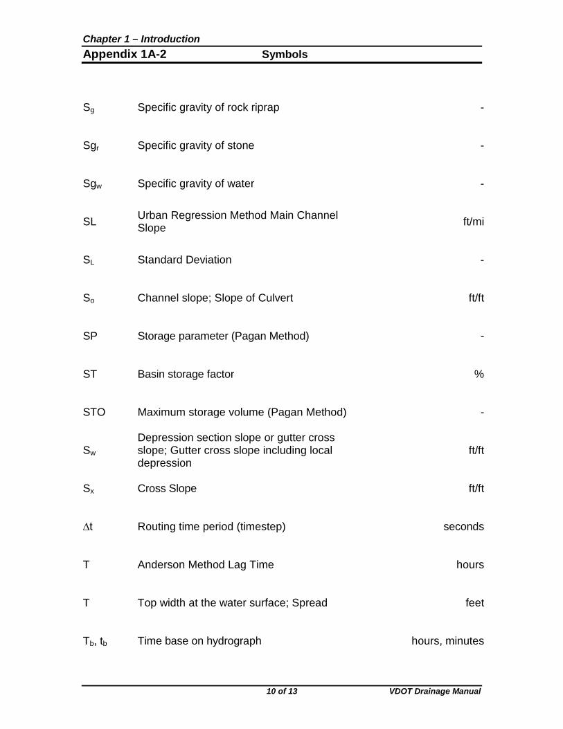
Sg Specific gravity of rock riprap
-
Sgr Specific gravity of stone
-
Sgw Specific gravity of water
-
SL Urban Regression Method Main Channel Slope
ft/mi
SL Standard Deviation
-
So Channel slope; Slope of Culvert
ft/ft
SP Storage parameter (Pagan Method)
-
ST Basin storage factor
%
STO Maximum storage volume (Pagan Method)
-
Sw Depression section slope or gutter cross slope; Gutter cross slope including local depression
ft/ft
Sx Cross Slope
ft/ft
∆t Routing time period (timestep)
seconds
T Anderson Method Lag Time
hours
T Top width at the water surface; Spread
feet
Tb, tb Time base on hydrograph
hours, minutes

Chapter 1 – Introduction
Appendix 1A-2 Symbols
11 of 13 VDOT Drainage Manual
Tc, tc Time of concentration; Modified Critical Storm Duration
minutes
Td Critical storm duration
minutes
Ti Duration of basin inflow
hours, minutes
τmax Maximum tractive force
lbs/ft2
τo Average tractive force
lbs/ft2
Tp Time to Peak
minutes
τp Permissible shear stress
lbs/ft2
Tr Time to Recede
minutes
τs Side slope shear stress
lbs/ft2
Ts Spread over depressed section
feet
Tt Travel time
hours
TW Tailwater depth above invert of culvert
feet
UQ Urban Regression Method peak runoff rate
cfs
UQT Peak runoff rate for Urban Watershed for Return Period T
cfs
V Mean velocity; Average velocity of flow; Velocity of flow in gutter
fps
V Storage volume

Chapter 1 – Introduction
Appendix 1A-2 Symbols
12 of 13 VDOT Drainage Manual
ft3, ac-ft.
Va Average velocity in main channel
fps
VB Average velocity at riprap basin overflow
fps
Vce Channel erosion control volume
ft3, ac-ft.
Vd Average velocity in downstream channel
fps
VL Average velocity at length (L) downstream from brink
fps
Vo Average velocity of flow at culvert outlet; Gutter velocity where splash-over first occurs
fps
Vs Storage volume estimate
ft3, ac-ft.
Vu Average velocity in upstream channel
fps
Vw Wave velocity
fps
W Drainage area width; Width of depression; Width of gutter pan; Width of grate
feet
W Minimum weight of outside stones for no damage
tons
W50 Weight of the 50% size stone
lbs.
WB Width of riprap basin at overflow
feet
Wo Width dimension of culvert shape
feet
WQV Water quality volume
ft3

Chapter 1 – Introduction
Appendix 1A-2 Symbols
13 of 13 VDOT Drainage Manual
X Logarithm of the annual peak
-
y Depth of flow in approach gutter
feet
Z T/d, reciprocal of the cross slope
-
z Elevation head
feet
α Velocity distribution coefficient
-
α Angle of face slope from the horizontal degrees
θ Side slope angle; Angle with respect to centerline of outlet pipe; Angle of embankment with respect to the horizontal
degrees
ρ 70˚ for randomly placed rubble degrees
φ Angle of repose of material
degrees
γ Unit weight of water lbs/ft3

![PERSONAL MEMORANDA [Office Copy]](https://static.fdocuments.net/doc/165x107/61bd3a5561276e740b10a203/personal-memoranda-office-copy.jpg)