New Electronic Billing Meter Standards Shocking Utilities ...

COLLIER COUNTY UTILITIES STANDARDS MANUALTABLE OF REVISIONS COLLIER COUNTY PUBLIC UTILITIES PLANNING AND PROJECT MANAGEMENT DEPARTMENTAS OF 09/2014
Item Section Sub-Section/ Detail #
Revision Summary Comments/Notes Fiscal Impact to Developer Page
1 1 Design Criteria
1.1 Pipe and Fitting Material
Remove Fusible PVC. Remove maximum lead percentages in conflict with Safe Drinking Water Act. Remove redundant language. Add clarity to directional drill requirements.
Fusible PVC field repairs are problematic. The Reduction in Lead in Drinking Water Act is more restrictive than the sentence removed. The directional drill requirements are consistent with the technical specifications.
None. 6
2 1 Design Criteria
1.2.2 Distribution System Layout
Update dead end looping requirements. The requirement for looped systems provides greater reliability and minimizes the adverse impacts of main breaks or maintenance.
Additional cost to extend main to the limits of the project.
7
3 1 Design Criteria
1.3.1 Subaqueous Canal Crossings
Update language referencing CDES to GMD. Simple clarification. None. 7
4 1 Design Criteria
1.4 Fire Service Systems
Update reference of meters to backflow preventers. Simple clarification. None. 8
5 1 Design Criteria
1.6.2 Water Meters Update language on deviation from determined meter size.
Simple clarification. None. 8
6 1 Design Criteria
Part 2 Wastewater Collection and Transmission Systems
Update design criteria language to use 250 gallons per day per residential unit and add reference to Collier County Industrial Pretreatment Ordinance.
The design criteria language will ensure consistency in wastewater system design.
None. 9
7 1 Design Criteria
2.1.2 Design of Pipeline Size, Depth and Location
Remove redundant language. Update reference of CDED to GMD. Remove gravity sewer anchor reference and table.
Simple clarifications and unnecessary table. None. 9 to 10
8 1 Design Criteria
2.1.5 Manholes Remove "recommended" from the description of maximum distance between manholes.
Simple clarification. None. 11
9 1 Design Criteria
2.2.1 Pipe and Fitting Materials
Remove Fusible PVC. Remove limitation of 700 feet of private force main. Clarify check valve requirement to delineate County owned and privately owned. Remove unnecessary language. Add clarity to directional drill requirement. Add "licensed".
Fusible PVC field repairs are problematic. The public ROW allows private utilities with no length limitations. A check valve provides a clear delineation between ownership. If a smaller diameter force main is needed to meet velocity requirements, a deviation is required either way. The directional drill requirements are consistent with the technical specifications.
Additional cost of a check valve that some may have not provided in the past.
11 to 12
10 1 Design Criteria
2.2.2 Design of Pipeline Size and Location
Add maximum velocity language. Remove unnecessary language. Add clarity to restraints. Add language to optimize air release valves (ARV's) and force main design. Remove language allowing force main connections directly to the manhole unless shown in the standards.
The maximum velocity limit is needed to minimize head loss and maintain efficiencies. The restraints are required in the Technical Specifications. Minimizing ARV's will reduce installation and maintenance costs. Force mains connecting directly to manholes can cause odor issues.
Potential cost savings by minimizing wastewater ARV's.
12
11 1 Design Criteria
2.2.4 Force Main Extension Stubs
Add requirement for a cap or plug on the stub-out valve.
The cap or plug will reduce the potential for leaks and is an industry standard.
Additional cost of cap/plug. 13
CHANGES TO UTILITIES STANDARDS MANUAL
Page 1 of 48

COLLIER COUNTY UTILITIES STANDARDS MANUALTABLE OF REVISIONS COLLIER COUNTY PUBLIC UTILITIES PLANNING AND PROJECT MANAGEMENT DEPARTMENTAS OF 09/2014
Item Section Sub-Section/ Detail #
Revision Summary Comments/Notes Fiscal Impact to Developer Page
2.3 Wastewater Pump Stations
Update all references of "pumping stations" to "pump stations". Minimal language edits for clarification.
Simple clarification. None. 13 to 15
Remove valve vault language. Valves and piping are being brought above ground to reduce corrosion and eliminate confined space constraints during maintenance activities.
Cost savings by removing need for precast vault.
13
Add requirement for variable frequency drives (VFD) on pumps with twenty or more horsepower.
20 hp pumps need to have the operating speed varied based on wet well water levels to improve system operation and control.
Additional cost of VFD and equipment when required.
14
Remove Master Pump Station language and add that stations with peak design flow of greater than 500 gallons per minute (gpm) require coordination with Public Utilities.
Pump stations with peak design flows greater than 500 gpm are not common and are typically constructed by the County.
None. 14
Remove Submaster Pump Station language and add Community Pump Station language. Community Pump Stations are the last station connected directly to the County transmission force main in each development.
Community Pump Stations require uninterrupted pumping capability like former Submaster Pump Stations but don't require odor control systems initially.
Additional cost of a generator or stand-by pump (engineer's option) in each development that may not have had a submaster pump station in the past.
14
Remove providing 4" conduit for water service to pump stations. Remove requiring a well if water is unavailable.
If water service is needed in the future, a service will be added without conduit. Wells aren't necessary.
Potential cost savings by removing 4" conduit.
14
Update pump station landscaping language to be optional and be located not to block access or interfere with operations.
Clarification None. 14 to 15
333200 Pump Stations
Update all references of "pumping stations" to "pump stations". Minimal language edits for clarification.
Simple clarification. None. 16 to 22
333200 Pump Stations, 2.1.B
Remove valve vault language and update to Above-Ground Valves and Piping.
Valves and piping are being brought above ground to reduce corrosion and eliminate confined space during maintenance activities.
Cost savings by removing precast vault.
17
333200 Pump Stations, 2.1.D
Update access cover language to always require H-20 loading.
Access covers should be consistent for ease of maintenance.
Potential additional cost of H-20 rated access cover.
18
333200 Pump Stations, 2.1.E
Update discharge pipes to HDPE from Ductile Iron. HDPE stands up over time to H2S gasses better than Ductile Iron.
Additional cost to use HDPE vs. Ductile Iron.
18
333200 Pump Stations, 2.1.F
Update pipe supports to stainless steel instead of masonry or concrete piers.
Stainless steel pipe supports cradle the pipe and provide adjustability.
Additional cost to use stainless steel supports instead of masonry.
18 to 19
333200 Pump Stations, 2.1.P
Remove odor control language and add concrete slab requirement for potential future odor control systems.
Odor control systems are now installed on an as-needed basis and typically aren't needed at pump station install.
Cost savings by removing odor control requirement.
21 to 22
12 1 Design Criteria
2 Technical Specifications
Page 2 of 48

COLLIER COUNTY UTILITIES STANDARDS MANUALTABLE OF REVISIONS COLLIER COUNTY PUBLIC UTILITIES PLANNING AND PROJECT MANAGEMENT DEPARTMENTAS OF 09/2014
Item Section Sub-Section/ Detail #
Revision Summary Comments/Notes Fiscal Impact to Developer Page
WW-7 Pump Station Detail - Profile
Update detail to not have a valve vault and show valves and pipes above ground. Remove Anchor Plate Detail (moved to new WW-7A detail). Add ARV on discharge pipes. Show invert in side view with drop connection. Changed discharge pipe to HDPE. Move vent pipe to top of wet well with pump out connection. Add discharge pipe supports.
ARV required due to high point. Drop connection added on gravity to minimize odors. Pump out connection will add operational flexibility to manage high flows. Discharge pipe supports will minimize movement of pipes within the wet well.
Cost savings with vault removal. Additional cost for ARV and pump out connections.
23
WW-7A Pump Station and Wastewater Details
Detail renamed. Berm detail remains. Added Anchor Plate detail from WW-7. Added Vent Pipe Detail. Added Wall Penetration Detail. Added Discharge Pipe Support Detail.
Organized small details for consistent installations.
Additional cost for vent pipe and wall penetration seals.
24
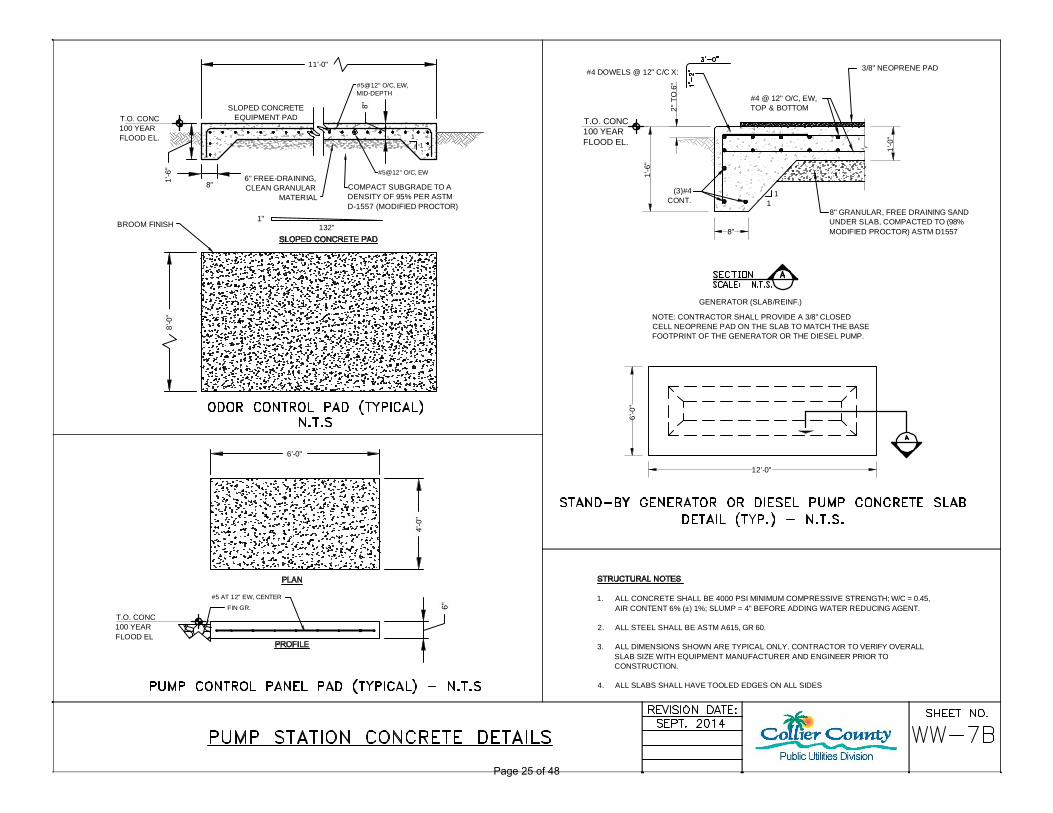
WW-7B Pump Station Concrete Details
New detail for Odor Control, Pump Control Panel, and Stand-by Generator/Diesel Pump Concrete Pads.
Organized details for consistent installations.
Additional cost for concrete pads. 25
WW-7C Pump Station and Wastewater Details
New detail for Pipe Support, Chain Link Fence, and Chain Link Fence Gate details.
Organized details for consistent installations.
Additional cost to use stainless steel supports instead of masonry.
26
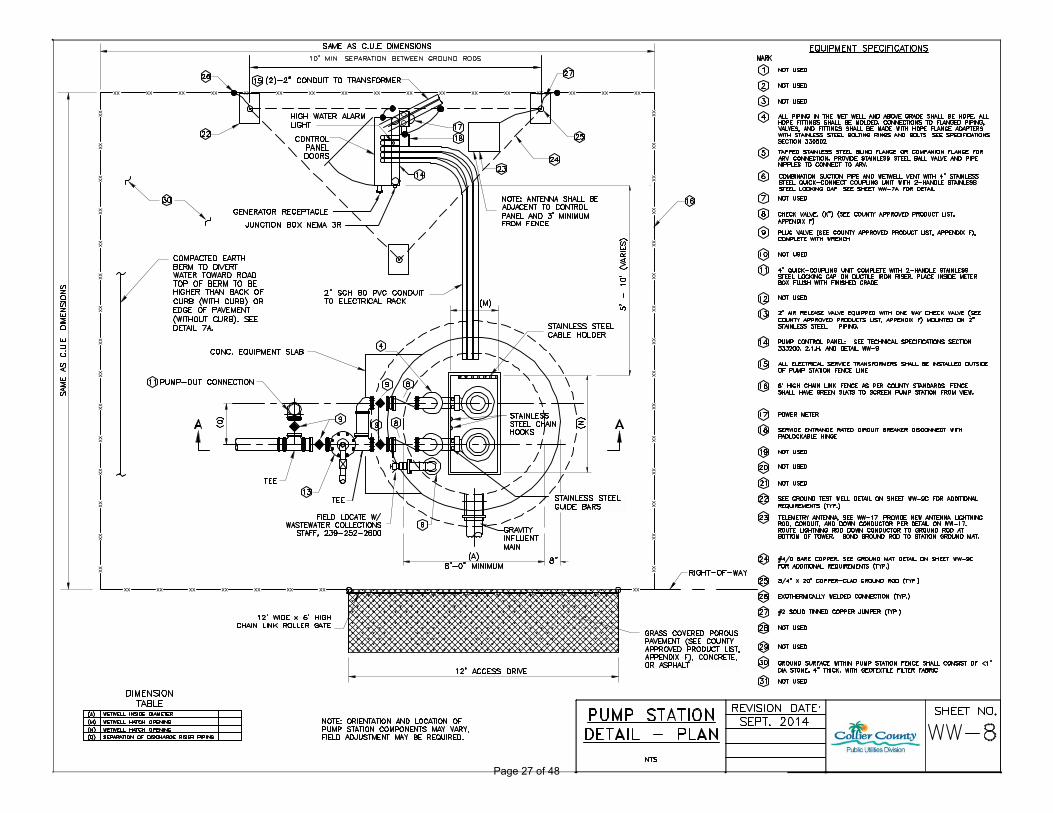
WW-8 Pump Station Detail - Plan
Update detail to not have a valve vault and show valves and pipes above ground. Add ARV on discharge pipes. Add grounding requirements. Change fence gate to rolling from swing. Remove odor control pad.
ARV required due to high point. Grounding requirements are necessary to protect staff against potential shock. Roll gates allow for trucks to be pulled off of the road while entering stations.
None. 27
WW-8A Community Pump Station with Generator Detail - Plan
New detail for Community Pump Stations with generators to show additional control panels required and location of generator. Also shows the required odor control pad.
New detail is necessary to show the differences between Community Pump Stations and regular pump stations.
None. 28
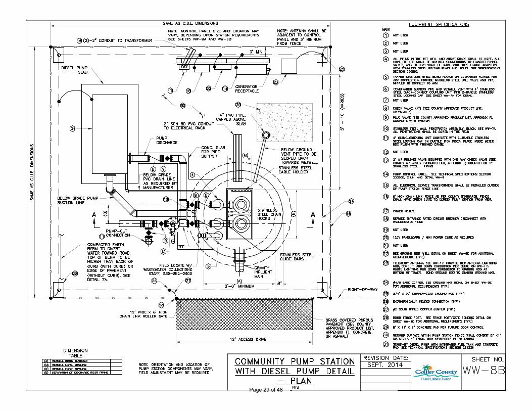
WW-8B Community Pump Station with Diesel Pump Detail - Plan
New detail for Community Pump Stations with diesel pump to show additional control panels required and location of diesel pump and required piping. Also shows the required odor control pad.
New detail is necessary to show the differences between Community Pump Stations and regular pump stations.
None. 29
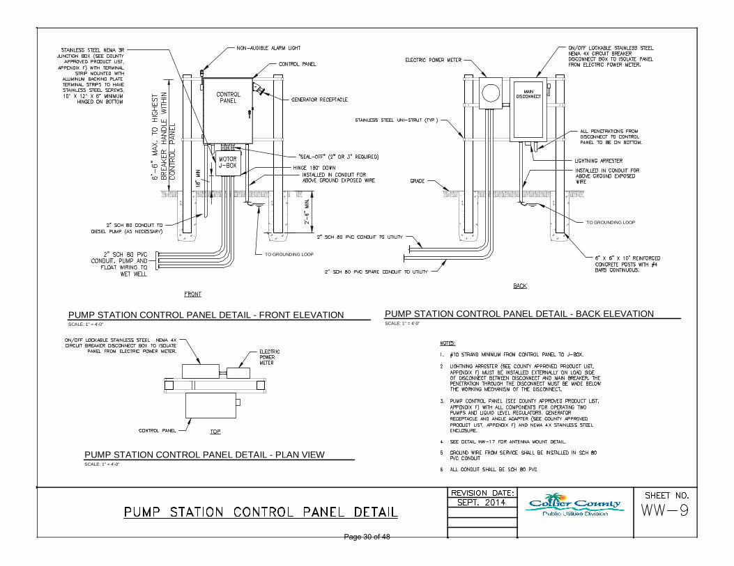
WW-9 Pump Station Control Panel Detail
Update detail to show plan, front elevation, and back elevation views. Remove vent pipe from control panel since now through top of wet well. Remove ground test well detail (on new WW-9C).
These changes add clarity to the existing detail.
None. 30
WW-9A Community Pump Station Control Panel Detail VFD Station with Generator
New detail for Community Pump Stations with VFD's and generators.
New detail is necessary to show the differences between Community Pump Stations and regular pump stations.
Additional costs associated with community pump stations.
31
12 3 Utility Details
Page 3 of 48
COLLIER COUNTY UTILITIES STANDARDS MANUALTABLE OF REVISIONS COLLIER COUNTY PUBLIC UTILITIES PLANNING AND PROJECT MANAGEMENT DEPARTMENTAS OF 09/2014
Item Section Sub-Section/ Detail #
Revision Summary Comments/Notes Fiscal Impact to Developer Page
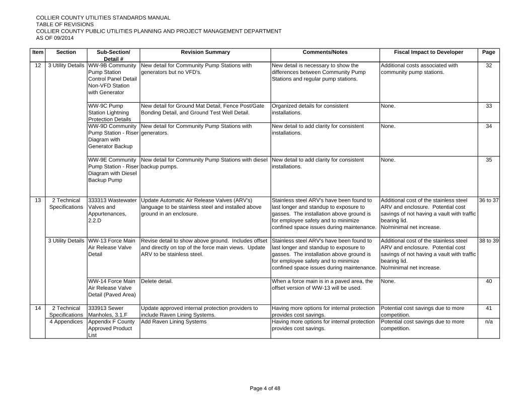
WW-9B Community Pump Station Control Panel Detail Non-VFD Station with Generator
New detail for Community Pump Stations with generators but no VFD's.
New detail is necessary to show the differences between Community Pump Stations and regular pump stations.
Additional costs associated with community pump stations.
32
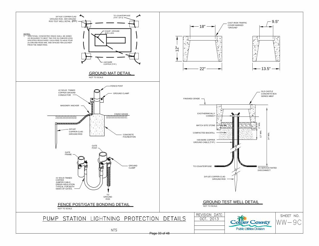
WW-9C Pump Station Lightning Protection Details
New detail for Ground Mat Detail, Fence Post/Gate Bonding Detail, and Ground Test Well Detail.
Organized details for consistent installations.
None. 33
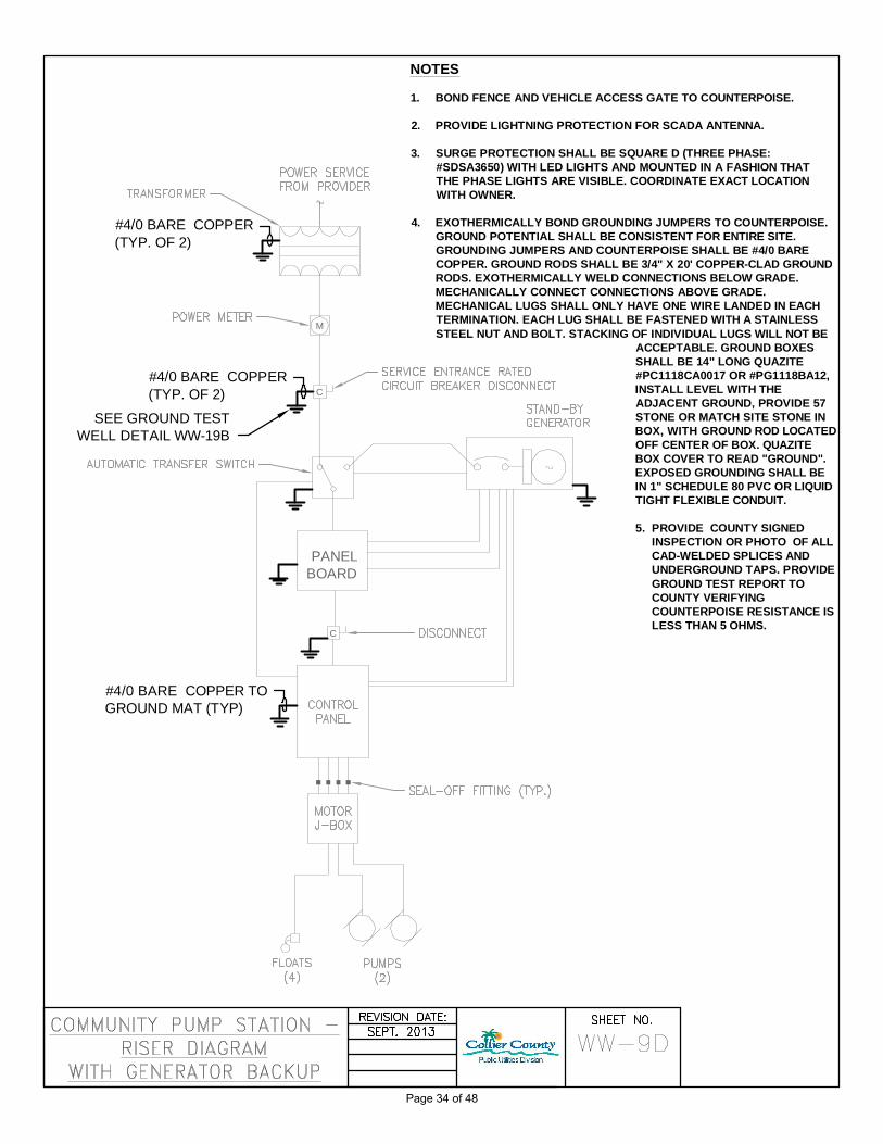
WW-9D Community Pump Station - Riser Diagram with Generator Backup
New detail for Community Pump Stations with generators.
New detail to add clarity for consistent installations.
None. 34
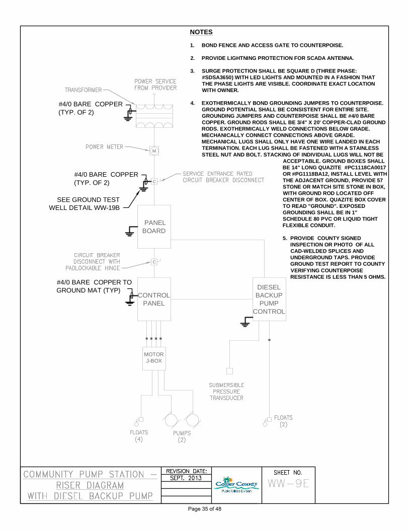
WW-9E Community Pump Station - Riser Diagram with Diesel Backup Pump
New detail for Community Pump Stations with diesel backup pumps.
New detail to add clarity for consistent installations.
None. 35
2 Technical Specifications
333313 Wastewater Valves and Appurtenances, 2.2.D
Update Automatic Air Release Valves (ARV's) language to be stainless steel and installed above ground in an enclosure.
Stainless steel ARV's have been found to last longer and standup to exposure to gasses. The installation above ground is for employee safety and to minimize confined space issues during maintenance.
Additional cost of the stainless steel ARV and enclosure. Potential cost savings of not having a vault with traffic bearing lid.No/minimal net increase.
36 to 37
WW-13 Force Main Air Release Valve Detail
Revise detail to show above ground. Includes offset and directly on top of the force main views. Update ARV to be stainless steel.
Stainless steel ARV's have been found to last longer and standup to exposure to gasses. The installation above ground is for employee safety and to minimize confined space issues during maintenance.
Additional cost of the stainless steel ARV and enclosure. Potential cost savings of not having a vault with traffic bearing lid.No/minimal net increase.
38 to 39
WW-14 Force Main Air Release Valve Detail (Paved Area)
Delete detail. When a force main is in a paved area, the offset version of WW-13 will be used.
None. 40
2 Technical Specifications
333913 Sewer Manholes, 3.1.F
Update approved internal protection providers to include Raven Lining Systems.
Having more options for internal protection provides cost savings.
Potential cost savings due to more competition.
41
4 Appendices Appendix F County Approved Product List
Add Raven Lining Systems Having more options for internal protection provides cost savings.
Potential cost savings due to more competition.
n/a
14
12 3 Utility Details
13
3 Utility Details
Page 4 of 48

COLLIER COUNTY UTILITIES STANDARDS MANUALTABLE OF REVISIONS COLLIER COUNTY PUBLIC UTILITIES PLANNING AND PROJECT MANAGEMENT DEPARTMENTAS OF 09/2014
Item Section Sub-Section/ Detail #
Revision Summary Comments/Notes Fiscal Impact to Developer Page
2 Technical Specifications
014500 Quality Control, 1.5.A.4
Add the Ten State Standards "Deformation Test" requirement on wastewater gravity sewers.
This test will ensure that the gravity sewer pipes installed are at least 95 percent round.
Minimal additional cost to be included with sewer viewing already required.
42 to 43
2 Technical Specifications
330130.16 Televising and Inspection of Gravity Sewer Systems, 2.2.A and 3.1.B
Add requirement for depth measurement device to be visible on sewer viewing video.
This is required to verify the new vertical deflection allowance.
Minimal additional cost to be included with sewer viewing already required.
44
2 Technical Specifications
3330518 Laying and Jointing Buried Pipe, 3.2.A
Add clarification that wastewater gravity sewer vertical dips shall not be greater than 1.5".
This clarification replaces the interpretation of no dips allowed.
None. 45
16 4 Appendices Appendix B Water Meter Sizing Form
Update demand ranges and notes on cover sheet. Minor change to fixture value worksheet.
Demand ranges up to 2" meet AWWA standards and larger than 2" meet manufacturer specifications.
Potential cost savings due to higher flows on smaller meters.
46 to 48
15
Page 5 of 48
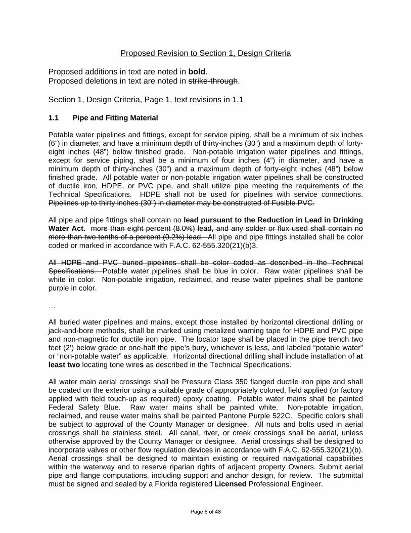
Proposed Revision to Section 1, Design Criteria Proposed additions in text are noted in bold. Proposed deletions in text are noted in strike-through. Section 1, Design Criteria, Page 1, text revisions in 1.1 1.1 Pipe and Fitting Material Potable water pipelines and fittings, except for service piping, shall be a minimum of six inches (6”) in diameter, and have a minimum depth of thirty-inches (30”) and a maximum depth of forty-eight inches (48”) below finished grade. Non-potable irrigation water pipelines and fittings, except for service piping, shall be a minimum of four inches (4”) in diameter, and have a minimum depth of thirty-inches (30”) and a maximum depth of forty-eight inches (48”) below finished grade. All potable water or non-potable irrigation water pipelines shall be constructed of ductile iron, HDPE, or PVC pipe, and shall utilize pipe meeting the requirements of the Technical Specifications. HDPE shall not be used for pipelines with service connections. Pipelines up to thirty inches (30”) in diameter may be constructed of Fusible PVC. All pipe and pipe fittings shall contain no lead pursuant to the Reduction in Lead in Drinking Water Act. more than eight percent (8.0%) lead, and any solder or flux used shall contain no more than two tenths of a percent (0.2%) lead. All pipe and pipe fittings installed shall be color coded or marked in accordance with F.A.C. 62-555.320(21)(b)3. All HDPE and PVC buried pipelines shall be color coded as described in the Technical Specifications. Potable water pipelines shall be blue in color. Raw water pipelines shall be white in color. Non-potable irrigation, reclaimed, and reuse water pipelines shall be pantone purple in color. … All buried water pipelines and mains, except those installed by horizontal directional drilling or jack-and-bore methods, shall be marked using metalized warning tape for HDPE and PVC pipe and non-magnetic for ductile iron pipe. The locator tape shall be placed in the pipe trench two feet (2’) below grade or one-half the pipe’s bury, whichever is less, and labeled “potable water” or “non-potable water” as applicable. Horizontal directional drilling shall include installation of at least two locating tone wires as described in the Technical Specifications. All water main aerial crossings shall be Pressure Class 350 flanged ductile iron pipe and shall be coated on the exterior using a suitable grade of appropriately colored, field applied (or factory applied with field touch-up as required) epoxy coating. Potable water mains shall be painted Federal Safety Blue. Raw water mains shall be painted white. Non-potable irrigation, reclaimed, and reuse water mains shall be painted Pantone Purple 522C. Specific colors shall be subject to approval of the County Manager or designee. All nuts and bolts used in aerial crossings shall be stainless steel. All canal, river, or creek crossings shall be aerial, unless otherwise approved by the County Manager or designee. Aerial crossings shall be designed to incorporate valves or other flow regulation devices in accordance with F.A.C. 62-555.320(21)(b). Aerial crossings shall be designed to maintain existing or required navigational capabilities within the waterway and to reserve riparian rights of adjacent property Owners. Submit aerial pipe and flange computations, including support and anchor design, for review. The submittal must be signed and sealed by a Florida registered Licensed Professional Engineer.
Page 6 of 48

Item 1
Proposed Revision to Section 1, Design Criteria Proposed additions in text are noted in bold. Proposed deletions in text are noted in strike-through. Section 1, Design Criteria, Page 3, text revisions in 1.2.2 1.2 Design of Pipeline Size and Location
1.2.2 Distribution System Layout … Generally, nNew potable water distribution systems shall be designed as “looped” systems to avoid dead ends. A “looped” system should have two independent connections off the source main (unless served by a master meter). If two independent connections aren’t possible, a stub out for future development in a location agreed to by the County shall be provided in an easement or ROW to the limits of the project. If changes in design during construction result in dead ends to any new or relocated water mains, such dead ends shall be connected to the nearest water main. In cases where no nearby water main is available, a County approved automatic flushing device shall be provided at each dead end of a water main and, if applicable, also near the mid-point of a looped water main unless the design engineer can provide information to confirm that the minimum residual chlorine will be maintained based on the predicted water consumption at the time of County acceptance of the water main. At no time shall a dead end serve more than 149 residential units. For phased projects, temporary automatic flushing devices can be relocated for future phases, if not conveyed to County. Section 1, Design Criteria, Page 5, text revisions in 1.3.1 1.3 Conflict Crossings 1.3.1 Subaqueous Canal Crossings … All subaqueous crossings must be introduced/discussed at a plan Pre-Submittal Conference. It is important that representatives from the Water Department or Wastewater Department and CDES GMD be present for approval at the plan Pre-Submittal Conference. …
Page 7 of 48

Item 1
Proposed Revision to Section 1, Design Criteria Proposed additions in text are noted in bold. Proposed deletions in text are noted in strike-through. Section 1, Design Criteria, Page 6, text revisions in 1.4 1.4 Fire Service Systems All private fire service systems for sprinkler systems, wet standpipe systems, and privately-owned or controlled distribution systems shall be installed with an appropriate backflow prevention device with a leak detection meter. The meter backflow device shall be sized by the Developer’s Engineer and shall be purchased, owned and maintained by the private service owner. The COUNTY requires all privately-owned backflow devices to be certified at the time of installation and on an annual basis by a Certified Backflow Tester (University of Florida, TREEO Center, or equivalent certification program). The results shall be submitted to the County Manager or designee. The County Manager or designee will require all privately owned metering devices to be certified for accuracy at the time of installation. Fire meter devices using a three quarter to two inch (¾” to 2”) metering device shall be re-calibrated to manufacturer’s specifications every five (5) years, replaced every ten (10) years, or replaced immediately upon meter failure. Fire meter devices greater than two inches (2”) shall be re-calibrated to manufacturer’s specifications every five (5) years and replaced immediately upon meter failure. The County Manager or designee will inform the owner by mail prior to the due date. Private owner(s) shall submit certification results to the County Manager or designee within sixty (60) days of the due date. Section 1, Design Criteria, Page 7, text revisions in 1.6.2 1.6 Water Services 1.6.2 Water Meters Water meters shall be properly sized, based on the total calculated service demand for water, according to the Collier County Water Meter Sizing Form (Appendix B). The properly sized water meter shall be installed according to specifications and standards. Any deviation from the determined meter size shall require an approved Deviation Request, if the meter is two inches (2”) or larger in size. …
Page 8 of 48
SECTION 1
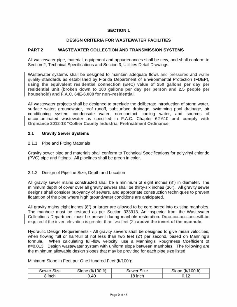
DESIGN CRITERIA FOR WASTEWATER FACILITIES PART 2 WASTEWATER COLLECTION AND TRANSMISSION SYSTEMS All wastewater pipe, material, equipment and appurtenances shall be new, and shall conform to Section 2, Technical Specifications and Section 3, Utilities Detail Drawings. Wastewater systems shall be designed to maintain adequate flows and pressures and water quality standards as established by Florida Department of Environmental Protection (FDEP), using the equivalent residential connection (ERC) value of 250 gallons per day per residential unit (broken down to 100 gallons per day per person and 2.5 people per household) and F.A.C. 64E-6.008 for non–residential. All wastewater projects shall be designed to preclude the deliberate introduction of storm water, surface water, groundwater, roof runoff, subsurface drainage, swimming pool drainage, air conditioning system condensate water, non-contact cooling water, and sources of uncontaminated wastewater as specified in F.A.C. Chapter 62-610 and comply with Ordinance 2012-13 “Collier County Industrial Pretreatment Ordinance. 2.1 Gravity Sewer Systems 2.1.1 Pipe and Fitting Materials Gravity sewer pipe and materials shall conform to Technical Specifications for polyvinyl chloride (PVC) pipe and fittings. All pipelines shall be green in color. 2.1.2 Design of Pipeline Size, Depth and Location All gravity sewer mains constructed shall be a minimum of eight inches (8”) in diameter. The minimum depth of cover over all gravity sewers shall be thirty-six inches (36”). All gravity sewer designs shall consider buoyancy of sewers, and appropriate construction techniques to prevent floatation of the pipe where high groundwater conditions are anticipated. All gravity mains eight inches (8”) or larger are allowed to be core bored into existing manholes. The manhole must be restored as per Section 333913. An inspector from the Wastewater Collections Department must be present during manhole restoration. Drop connections will be required if the invert elevation is greater than two feet (2’) above the invert of the manhole. Hydraulic Design Requirements - All gravity sewers shall be designed to give mean velocities, when flowing full or half-full of not less than two feet (2’) per second, based on Manning’s formula. When calculating full-flow velocity, use a Manning’s Roughness Coefficient of n=0.013. Design wastewater system with uniform slope between manholes. The following are the minimum allowable design slopes that may be provided for each pipe size listed: Minimum Slope in Feet per One Hundred Feet (ft/100’):
Sewer Size Slope (ft/100 ft) Sewer Size Slope (ft/100 ft) 8 inch 0.40 18 inch 0.12
Page 9 of 48

10 inch 0.28 21 inch 0.10 12 inch 0.22 24 inch 0.08 15 inch 0.15
Special attention shall be given to gravity lines that receive flows from wastewater transmission or re-pumping facilities. Due care shall be taken in these cases to ensure that no surcharge conditions occur downstream due to excessive flow rates. Under no conditions shall pipe of a diameter larger than that necessary for proper hydraulic design as determined by the COUNTY Community Development and Environmental ServicesGrowth Management Division or Public Utilities Planning and Project Management Department be permitted for use on any project. Sewers to be located on 20% slopes or greater shall be designed with anchors secured into concrete with anchors spaced as follows:
Grade Range Anchor Spacing 20% - 35% 36 feet center to center 35% - 50% 24 feet center to center
50% and higher 16 feet center to center Pipeline separation criteria and conflict crossings criteria shall conform to the requirements described in Part 1, Sections 1.2.3 and 1.3. All sewers shall be designed to prevent superimposed loads. 2.1.3 Gravity Sewer Main Extension Stubs All main-line extension stubs to future developments and/or parcels shall terminate in a stub-out if it is part of a phased project. The stub-out shall end with a bell. 2.1.4 Gravity Sewer Laterals Laterals shall be extended to the property line or easement limit for all installations. Laterals shall be a minimum of six inches (6”) in diameter. Lateral shall have a minimum depth of thirty inches (30”) and a maximum depth of forty-eight inches (48”) below finished grade. In locations where a minimum depth of thirty inches (30”) cannot be provided, laterals shall be C900, DR 14 PVC pipe. At no time shall the depth of a lateral be less than twenty-four inches (24”). At no time shall a lateral be core bored into manholes. Upon installation, all lateral ends shall be plugged. A cleanout shall be provided at the end of each lateral prior to the end plug. Typical lateral and cleanout standards are shown in the Utilities Detail Drawings. The cleanout riser and cap shall be set twenty-four inches (24”) above finished grade. All sewer lateral ends shall be provided with an electronic marker (see County Approved Product List, Appendix F). Electronic markers shall be placed twenty-four inches (24”) below final grade at the cleanout, for COUNTY inspector to see during final plumbing tie-in inspection. At no time shall the connection to the lateral be made to the cleanout riser or any part of the vertical assembly. Either a single six inch (6”) diameter or larger lateral to each property or a single six inch (6”) or larger lateral with a double wye shall be provided.
Page 10 of 48

2.1.5 Manholes Precast concrete manholes shall be installed at the end of each wastewater main, at all changes in grade, size, or horizontal alignment, and at all main pipe intersections, shall be spaced at distances not greater than four hundred feet (400’) and shall be placed in roads. For sanitary sewers with a diameter greater than fifteen inches (15”), the recommended maximum distance between manholes is four hundred fifty feet (450’). All gravity collection mains shall terminate in a precast manhole. Minimum inside diameter of all manholes shall be four feet (4’). A drop pipe shall be provided for a sewer entering a manhole at an elevation of twenty-four inches (24”) or more above the manhole invert. Drop manholes shall be constructed with an outside drop connection encased in concrete, as shown in the Utilities Detail Drawings. See FDEP Wastewater Checklist Form 62-604.300(8)(a), “Manholes” section, for further design requirements, as well as Specification Section 333913 and the Detail Drawings. 2.2. Force Mains 2.2.1 Pipe and Fitting Materials Force main pipelines and fittings shall be a minimum of four inches (4”) in diameter. All force mains between four and fourteen inches (4”-14”) in diameter shall be constructed of PVC or HDPE pipe and shall utilize pipe meeting the requirements of the Technical Specifications. Force mains sixteen inches (16”) and larger in diameter shall be constructed of ductile iron, HDPE, or PVC pipe. Pipelines up to thirty inches (30”) in diameter may be constructed of Fusible PVC. Deviations from the minimum four inch (4”) diameter pipeline design parameters shall only be approved in cases where such installations are necessary in order to comply with minimum FDEP velocity requirements. Whenever the minimum four inch (4”) diameter pipeline cannot be provided, a COUNTY approved deviation form will be required. The Owner shall be responsible for maintaining seven hundred feet (700’) of the smaller diameter force main located within the County ROW. No A check valve will be required to delineate County owned and privately owned. Due to minimum velocity requirements as set forth by the FDEP, one and a half inch (1-1/2”) diameter force mains may be required. If so, force mains shall conform to Section 2, Technical Specifications. All HDPE and PVC buried pipelines shall be color-coded as described in the Technical Specifications. Force main pipelines shall be green in color. Buried force mains, except those installed by directional drill or jack-and-bore methods, shall be marked using metalized warning tape for PVC pipe and non-magnetic for ductile iron pipe. The metalized warning tape shall be placed in the pipe trench at two feet (2’) below grade or one-half the depth of the pipe’s bury, whichever is less, and labeled “WASTEWATER FORCE MAIN.” Electronic markers (see County Approved Product List, Appendix F) shall be placed twenty-four inches (24”) below final grade, above the force main, at all bends or changes in alignment, valves, and every two hundred fifty feet (250’). Horizontal directional drilling shall include installation of at least two locating tone wires as described in the Technical Specifications.
Page 11 of 48
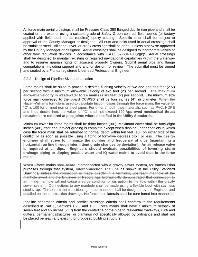
All force main aerial crossings shall be Pressure Class 350 flanged ductile iron pipe and shall be coated on the exterior using a suitable grade of Safety Green colored, field applied (or factory applied with field touch-up as required) epoxy coating. Specific color shall be subject to approval of the County Manager or designee. All nuts and bolts used in aerial crossings shall be stainless steel. All canal, river, or creek crossings shall be aerial, unless otherwise approved by the County Manager or designee. Aerial crossings shall be designed to incorporate valves or other flow regulation devices in accordance with F.A.C. 62-604.400(2)(k)5. Aerial crossings shall be designed to maintain existing or required navigational capabilities within the waterway and to reserve riparian rights of adjacent property Owners. Submit aerial pipe and flange computations, including support and anchor design, for review. The submittal must be signed and sealed by a Florida registered Licensed Professional Engineer. 2.2.2 Design of Pipeline Size and Location Force mains shall be sized to provide a desired flushing velocity of two and one-half feet (2.5’) per second with a minimum allowable velocity of two feet (2’) per second. The maximum allowable velocity in wastewater force mains is six feet (6’) per second. The minimum size force main conveyed to the Board CCWSD shall be four inches (4”) in diameter. When the Hazen-Williams formula is used to calculate friction losses through the force main, the value for “C” is 100 for unlined iron or steel pipes. For other smooth pipe materials, such as PVC, HDPE and lined ductile iron, the value for “C” shall not exceed 120.Approved mechanical thrust restraints are required at pipe joints where specified in the Utility Standards. Minimum cover for force mains shall be thirty inches (30”). Maximum cover shall be forty-eight inches (48”) after final project grading is complete except when dipping under conflicts in which case the force main shall be returned to normal depth within ten feet (10’) on either side of the conflict or as soon as possible using a fitting of forty-five degrees (45°) or less. The design engineer shall strive to minimize the number and frequency of dips (maintaining a horizontal run line through intermittent grade changes by deviation). An air release valve is required at all dips. Engineers should evaluate possibilities of lowering storm drainage piping or dipping potable water and IQ water mains to avoid dips in the force main. When Fforce mains shall beare interconnected with a gravity sewer system, for transmission purposes through that system, interconnection shall be as shown in the Utility Standard Drawings, unless the connection is made directly in a terminus, upstream manhole at the manhole invert and the Engineer of Record has hydraulically demonstrated that connection to an in-line manhole will not cause a surge condition or disruption to the flow within the gravity sewer system. Connections to any manhole shall be made using a flexible boot with stainless steel strap. Thrust restraint transitioning to the manhole shall be designed by the Engineer and detailed on the construction drawings. No force main laterals shall be core bored into manholes. Pipeline separation criteria and conflict crossings criteria shall conform to the requirements described in Part 1, Sections 1.2.3 and 1.3. Force mains shall have a minimum setback of seven feet and six inches (7’6”) from the centerline of the pipe to residential roadways, curb and gutters, permanent structures, or plantings not specifically allowed by ordinance and shall not be placed beneath any existing or proposed building structure.
Page 12 of 48

2.2.3 Valves All connections of privately-owned and maintained wastewater force mains to the Wastewater Department’s force mains shall be connected through a check valve housed in a structure as shown in the Utilities Detail Drawings which shall allow performance of required maintenance, and shall be owned and maintained by the property owner. Sufficient plug valves shall be provided to allow for zone isolation of wastewater transmission areas in order to limit the impact of line breaks. In-line plug valves shall be provided at no greater than one thousand foot (1,000’) intervals per COUNTY requirements. 2.2.4 Force Main Extension Stubs All main-line extension stubs to future developments and/or parcels shall terminate in a stub-out if it is part of a phased project. The stub-out shall end with a valve and cap/plug. 2.2.5 Air Release Assemblies Air release assemblies shall be provided at all high points and on the upstream side of conflict crossings at which the force main passes under the conflict (unless it can be demonstrated by hydraulic analysis that air pockets will not accumulate at individual high points). A high point is defined by the hydraulic gradient and is considered the upper end of any pipe segment that slopes up to the hydraulic gradient or runs parallel to it. Air valves (see County Approved Product List, Appendix F) utilized on raw sewage facilities shall be designed and manufactured specifically for use with domestic sewage. The design engineer shall review and apply the pertinent provisions of AWWA-C512 and AWWA Manual of Water Supply Practices M51, “Air-Release, Air Vacuum, and Combination Air Valves”. When installed, the air valve shall be provided with a shut-off valve to allow isolation and removal of the valve assembly. All air release assemblies shall be installed as shown in the Utilities Detail Drawings. 2.3 Wastewater Pumping Stations Wastewater pumping stations shall be designed and constructed in accordance with accepted engineering practices,FDEP regulatory requirements, Section 2 Technical Specifications, National Electrical Code (NEC) Requirements, and Section 3 Utilities Detail Drawings. Pumping Station wetwells and valve vaults shall be designed to withstand flotation forces with the assumption that the structures are when empty and ground/flood water elevation is at the top of the structures. The design shall consider the potential for damage or interruption of operation because ofdue to flooding. Pump station structures and electrical and mechanical equipment shall be designed to be protected from physical damage by the 100-year flood event. Pump stations shall be designed to remain fully operational and accessible during the 25-year flood eventunless lesser flood levels are appropriate based on local considerations, but not less than the 10-year flood. Pump stations shall be designed to avoid operational problems from the accumulation of grit. Pump stations shall be designed to be readily accessible by maintenance vehicles, including pumper trucks, during all weather conditions. Pump stations shall be designed and located on the site to minimize adverse effects from odors, noise, and lighting. Pump stations shall be located on the site to have a minimum separation of twenty feet (20’) from the edge of the CUE for the pump station to edge of a body of water and fifteen feet (15’) from the edge of the CUE
Page 13 of 48

for the pump station to a residential structure (including appurtenances). Also see detail WW-7A for additional requirements. The effective volume of wet wells shall be based on design average flows and a filling time not to exceed 30 minutes unless the facility is designed to provide flow equalization. The pump manufacturer’s duty cycle recommendations shall be utilized in selecting the minimum cycling time. Pump stations requiring a pump motor of twenty horsepower or greater shall operate by a VFD (variable frequency drive) that varies the operating speed of the pump based on wet well water levels. Pump stations shall have a compacted earth berm on three sides with 3:1 slopes to divert liquid toward the ROW. Top of berm shall be twelve inches (12”) wide and six inches (6”) higher than back of curb (with curb) or edge of pavement (without curb). Minimum berm height shall be six inches (6”). See detail WW-7A for further detail. When a pump station has a peak design flow coming into the station greater than 500 gpm, contact Public Utilities Planning and Project Management Department for specifications. A Master Pumping Station is any station that (1) has a design flow per pump greater than 500 gpm or (2) may be determined by the Public Utilities Division as a Master Pumping Station. Such determination shall be made at the sole discretion of the Public Utilities Division where found to be in the public interest. A Master Pumping Station shall have permanent standby power generation, a pre-engineered biofiltration odor control system, and a one hundred foot (100’) minimum separation from the edge of the CUE to the edge of a body of water or residential structure (including appurtenances). A Master Pump Station shall be designed with a spill containment area to retain thirty (30) minutes of peak design flow. A pump station that is connected directly to the County transmission force main from a development (Community Pump Station) shall have uninterrupted pumping capability (standby diesel pump or generator) with three days of fuel storage (compliant with Technical Specification 263213) and a concrete pad for a future odor control system. A Submaster Pumping Station is any station that (1) has a total design flow greater than 120 gpm with one pump operational and receives inflow from two or more upstream pump stations or (2) has a design flow per pump greater than 200 gpm or (3) may be determined by the Public Utilities Division as a Submaster Pumping Station. Such determination shall be made at the sole discretion of the Public Utilities Division where found to be in the public interest. A Submaster Pumping Station shall have permanent standby power generation and a pre-engineered biofiltration odor control system. All pump stations shall have water available to them. Available water means a water main is accessible in the adjacent ROW or CUE. If the water main is on the opposite side of the street from the pump station CUE, provide a four inch (4”) conduit from the nearest lot corner to on the opposite side of the street to a point five foot (5’) beyond the back of sidewalk on the same side of the street as the pump station. If no water is available, a well is required to provide water to the pump station. Well separation requirements shall be in accordance with F.A.C. The well and supply line shall be located in a CUE for maintenance. All pump stations equipped with a pre-engineered biofiltration odor control system shall have a standard potable water service with appropriate water meter and backflow preventer. Landscaping shallmay be installed around developer constructed pump stations that are intended to be conveyed to the Public Utilities Division. Said lLandscaping, if provided, shall
Page 14 of 48
be maintained by the developer, homeowners association, or land owner and shall NOT be located in the CUE. Landscaping, if provided, shall be located as to not block access or interfere with operationson the three sides without the gate and shall be at least 75% of the height of the fence at Final Acceptance of the pump station. Landscaping shall provide a minimum of 80% opacity at maturity and have a non-intrusive root structure. If required plant material dies, it is the responsibility of the landscaping owner to replace it. The landscaping shall be maintained to not block telemetry antenna line of site. 2.4 Connections to Collier County Facilities Connections to existing COUNTY wastewater mains shall be constructed as described in the Technical Specifications and shown in the Utilities Detail Drawings. These details shall apply to all connections to existing systems. All projects shall be designed with no physical connections between a public or private potable water supply system and a sewer or force main and with no water mains passing through or coming into contact with any part of a sewer manhole. 2.5 Tests and Inspections Tests and inspections of all wastewater systems or portion(s) thereof shall be performed in accordance with the Technical Specifications before acceptance of the systems or portions thereof by Collier County. 2.6 Wastewater Pumping Station Asset Management Asset management is required for proper use and maintenance of these wastewater facilities. State of Florida DEP regulations state: “…systems shall be operated and maintained so as to provide uninterrupted service…” To accomplish this obligation on privately owned wastewater pumping stations, the owner(s) of each such station shall:
A. Maintain a permanent fence with a sign mounted thereon, which sign shall include the correct name and phone number(s) of at least one emergency contact individual and the correct name(s) and phone number(s) of the station’s operator as well as the station’s owner(s). The text on the sign must be immediately updated if and when any of the information on the sign becomes outdated.
B. The station’s owner shall continuously retain (contract with) an operator qualified under
Florida laws, rule or regulation, for Operations, Preventive Maintenance, and to respond to each service interruption, if any, at that station.
The above requirements are mandated by the Florida Department of Environmental Protection regulations: Florida Administrative Code, Subsection 62-604.500. Also refer to the Standard Details for additional information that applies to the above noted signage requirements.
Page 15 of 48

SECTION 333200
PUMPING STATIONS
PART 1 GENERAL 1.1 SCOPE OF WORK
A. This section includes the following items: wet wells, valve vaults, access covers, pumps, wet well equipment, valves, emergency bypasses, pump control panels, pump controller/RTU, antenna subsystem, disconnects, electric meters, electric service, pump wiring, lightning arrestors, and pre-engineered biofiltration odor control systems.
B. Conform all pumping stations to the specifications, Utilities Detail Drawings, and
latest National Electrical Code (NEC) requirements.
B.C. When a pump station has a peak design flow coming into the station greater than 500 gpm, contact Public Utilities Planning and Project Management Department for specifications.
C.D. For systems eligible to be taken over by the COUNTY, provide enough room to
operate and maintain all water and wastewater systems in a simple and non-awkward manner. If a master meter or a pumping station pump needs to be replaced, provide enough room for the COUNTY to readily remove the pump, and to do so without interfering with traffic. In order to be eligible for conveyance to the COUNTY, the pumping station easement area must be designed to 30’X30’, or twice the depth of the wet well by twice the depth of the wet well, whichever is larger, as defined in the Collier County Standards and Procedures Ordinance, Subsection 7.7(c), as amended or superceded.
D.E. Schedule required COUNTY inspections of (1) pumping station installation prior to
cover-up and (2) pumping station start-up.
E.F. Install all fencing around the pumping station in accordance with Section 323113.
PART 2 EQUIPMENT 2.1 MATERIALS
A. Wet Well: The concrete structure shall consist of precast, reinforced sections conforming to ASTM C76 and/or ASTM C478. 8-foot diameter wet wells shall have a minimum wall thickness of 8 inches. Wall thickness for larger wet wells shall conform to ASTM standards for wall thickness, but shall not be less than 8 inches in any case. The minimum inside diameter for all wet wells eligible to be owned and maintained by Collier County shall be 8 feet. As a deviation, a 6-foot diameter wet well can be utilized if the ENGINEER can demonstrate that the wet
Page 16 of 48

well is sufficient hydraulically and the developer can demonstrate that the pumping station shall be used for the perpetual and exclusive use of that particular development. For pumping stations that will not be owned and maintained by Collier County, the ENGINEER shall set the design specifications for the wet well, provided such design does not in any way endanger the health, safety and/or welfare of the public. Base riser section shall be monolithically cast with the base slab. All concrete shall utilize Type 2 cement and have a minimum compressive strength of 4000 psi at twenty eight (28) days. On new construction, if more than one hole is abandoned and required to be cemented in, provide a new wet well barrel section. Reinforcing steel for all wet well structures should be sized by the unit manufacturer and verified by the ENGINEER. All connections to the wet well for gravity sewer piping shall be equal to those for manholes as described in Section 333913. Factory double coat all exterior surfaces with an acceptable bituminous or epoxy sealer a minimum of 18 mils thick. Seal all riser joints utilizing plastic joint sealing compound (see County Approved Product List, Appendix F) or other suitable bituminous or rubber sealing material. Reinforcement and top slab thickness shall be specified by the design ENGINEER for H-20 loadings in all cases. Minimum reinforced slab thickness shall be 8 inches. Typical standards for wet wells are available in the Collier County Standard Details. The ENGINEER shall be responsible for designing all wet well structures to overcome buoyancy forces exerted on the installed structure. Coat all wet well interiors with an acceptable field applied internal protection (see County Approved Product List, Appendix F) in accordance with Section 099723.
B. Above-Ground Valves and Piping Vault: The vault wall may be poured-in-place
concrete or pre-cast concrete. All concrete shall utilize Type 2 cement and have a minimum compressive strength of 4000 psi at twenty eight (28) days. A concrete base slab shall be utilized. Minimum slab thickness shall be 8 inches. Reinforcement and top slab thickness shall be as specified by the ENGINEER for H-20 loading in all cases. Vault shall be located as close to the wet well as possible. No direct opening between vault and wet well shall exist. Gravity drains from the vault to the wet well shall be required. All such drain lines shall terminate with a check valve (see County Approved Product List, Appendix F). Factory double coat all interior and exterior walls of vaults (minimum 18 mils thick) with an acceptable bituminous or epoxy sealer. Coat all interior surfaces of the valve vault with an acceptable field applied internal protection (see County Approved Product List, Appendix F) in accordance with Section 099723. Vault Above-ground valves and piping must be positioned so that it does not lie above any gravity sewer line entering the wet well, unless field conditions dictate otherwise and the COUNTY has granted prior approval. Enclose all tees, elbows and fittings transitioning the pumping station discharge piping into the force main running from the station within the vault walls. Vault interior sizing shall be adequate for maintenance and repair of all components within the vault. Typical above-ground valves and piping vault standards are located in the Collier County Standard Details. All pipe connections through the valve vault walls shall be made equal to pipe connections for manholes as discussed in Section 333913. The annular space around the boots shall not be grouted when the piping work is completed.
Page 17 of 48
C. Pumps: Sewage pumps (see County Approved Product List, Appendix F) shall be
of the submersible type suitable for operation in sewage of temperature not exceeding 115 degrees Fahrenheit. The use of flooded suction type pumping systems for master pump stations may be considered on a case-by-case basis and must be approved by the Wastewater Director prior to submittal of construction documents. Pump head curves and design specifications for each application proposed shall be submitted for review and approval within the ENGINEER’s hydraulic design report. All pumps shall be three-phase unless approved by a Utility Deviation Form. At least one (1) pump in each wet well shall be equipped with a mix-flush system (see County Approved Product List, Appendix F).
D. Access Covers: Access covers for pumping station wet wells and valve vaults
shall be above the 100-year flood elevation unless the structure is located within a documented velocity and tidal flood zone, and elevation differentials prohibit such installation. In such cases, watertight access covers shall be utilized. The ENGINEER shall provide shop drawings of such access covers for review and approval by THE County Manager or designee prior to use. Access covers shall be constructed of diamond plate aluminum sheets and aluminum structural members. All access covers shall be attached to aluminum angle frames with stainless steel hinges and fasteners. Angle frames shall be firmly anchored into the top concrete slab of the structure. All access covers shall be equipped with a ratchet-type restraint mechanism to prevent accidental closing of the cover and torsion bar or spring assist type openers. Assist openers shall be manufactured of stainless steel. Covers located in non-traffic areas shall be designed for loadings of not less than 150 pounds per square foot. Access covers located in traffic or potential traffic areas shall be designed for H-20 loadings. If found to be acceptable by the County Manager or designee, a system of 6 inch diameter concrete filled bollards may be substituted for the H-20 rated covers. A layout of such guard posts must be submitted to the County Manager or designee for approval prior to installation.
E. Wet Well Equipment: All pump discharge piping shall be ductile ironHDPE pipe,
pressure Class 250 and shall be in conformance with pipe utilized for wastewater force mains. All fittings shall be ductile ironHDPE fused, flange/flange, or Uni-Flange connections and shall be coated identically to wastewater force main fittings. All fittings shall have flange x flange or Uni-Flange connections. All nuts, bolts, fasteners, brackets, pump guide rails and other hardware located inside the wet well shall be 304 316 stainless steel. A 4 inch pump out with a screened vent shall be provided on all installations, with the vent pipe extended through the wet well lid (see details) above the top of the Control Panel. Electrical systems and components (e.g. motors, lights, cables, conduits, switch boxes, control circuits, etc.) in raw wastewater wetwells, or in enclosed or partially enclosed spaces where hazardous concentrations of flammable gases or vapors may be present shall comply with the National Electrical Code (NEC) requirements for Class I Group D, Division 1 locations. Electrical equipment located in wet wells shall be suitable for use under corrosive conditions.
Page 18 of 48

F. Valves: Discharge piping for each pump shall be equipped with a weighted check
valve and plug valve. A teethree way with an isolation plug valve, equipped with a quick coupling (see County Approved Product List, Appendix F), may be substituted for one plug valve to shall be provided for a means of emergency bypass access to the wastewater force main as required. Valves shall be supported by stainless steel pipe supports on masonry or concrete piers.
G. Emergency Bypass: A 34-inch emergency bypass connection shall be provided
down-stream from the in-line discharge piping valves. The connection shall lie within the vault, be readily accessible, and be equipped with a plug-type isolation valve and 3 4-inch male Kamlock type quick coupling and cap. A three-way plug valve may be equipped with the quick coupling in lieu of the separate emergency bypass.
H. Pump Control Panel (see County Approved Product List, Appendix F): Panel
enclosure construction shall be equal to a NEMA 3R or 4X stainless steel with 3-point latch where required and utilize stainless steel. When possible, Panel panel door shall open away from wetwell and not towards wetwell hatch to ensure safety during maintenance of wetwell and panel. To ensure proper installation of Control Panel, contact the Wastewater Department prior to rough-in or installation of Control Panel, for a pre-construction meeting with respective Wastewater Collections Personnel. Control panels shall be mounted on two 6 inch by 6 inch precast concrete posts. All mounting bars, nuts, bolts, etc. shall be stainless steel. A 110/120 volt (110V) receptacle shall be provided inside the control panel for pump stations that have outdoor control panels. Ground fault interruption (GFI) protection shall be provided for all outdoor outlets.
I. Pump Controller / RTU: Provide a pump control panel (see County Approved
Product List, Appendix F) including a TAC Pack TCU (RTU) for pump controlling purposes. At a minimum, the TAC Pack TCU shall include an integrated 2-Watt digital radio, an 18 amp hour back-up battery, a manufacturer’s prefabricated wire harness, all manufacturer recommended surge protection, and suitable devices for measuring wastewater flow. The TAC Pack TCU shall incorporate three on-board fail-safe HOA switches and Triplex/Duplex/Simplex configurable operation mode. An on-board 240 VAC or 460 three phase monitor shall be provided. The Alarm light and bell shall be activated by the TAC Pack TCU and the external push-button alarm silence switch shall be wired into the TAC Pack TCU. The TAC Pack TCU shall incorporate an on-board 4 by 20 character LCD display for elapsed runtime of each pump. During the automatic sequence the pumps shall be controlled in an alternate mode.
J. Antenna Subsystem: Provide a high gain antenna (see County Approved
Product List, Appendix F) for use to transmit and receive TAC Pack TCU data to and from the COUNTY’s existing TAC II SCADA server. Antenna shall utilize all welded-aluminum elements. Element connections utilizing nuts and bolts are not acceptable. Antenna shall have a single radiator element connected to a type N female connector. Antenna shall be supported on a mast/pole and have DC
Page 19 of 48

grounding for lightning protection. Antenna mounting hardware shall be made of stainless steel. Antenna shall meet or exceed the quality, reliability and performance of the RTA series as provided by Data Flow Systems, Inc. Antenna mast/pole shall be a 21foot by 1.25 inch SCH80 galvanized pole. Mounting of the antenna mast/pole shall be in accordance with all applicable local and state building codes as they pertain to structural strength and wind velocity requirements. Tower shall meet or exceed the quality and reliability of the AG20 manufactured by Rohn. Coaxial cable shall be RTC 400 as supplied by Data Flow Systems, Inc. Type N connectors shall be utilized at both ends of the coax. Type N connectors shall be sealed with 3 inch sections of Alpha FIT321-1-0 sealant shrink tubing. Coaxial cable shall be secured to the mast/pole with E.V.A.-coated 316 stainless steel cable ties. Cable ties shall meet or exceed the quality, reliability and performance of AE112 cable ties manufactured by Band-It. For pump stations to be conveyed to the County, a startup and successful testing of Data Flow telemetry equipment by Data Flow representatives and County Wastewater Collections instrumentation and telemetry representatives is required prior to County acceptance. After initial startup, for pump stations to be conveyed to the County, the latitude and longitude of pump stations shall be provided.
K. Disconnect: A non-fusedcircuit breaker disconnect shall be provided to isolate the
pump control panel. Disconnect shall be installed on the service line between the electric meter and control panel and shall be lockable in the “ON” or “OFF” position. Disconnects shall be housed in a NEMA 3R4X, stainless steel enclosure or better.
L. Electric Meter: The electric meter servicing the pumping station shall be located
adjacent to the pump control panel, and shall be located and wired so as to service only the pumping station facility.
M. Electric Service: All underground electric services shall be fully conduited in 2-inch
diameter Schedule 80 PVC pipe from the power company source point to the pump control panel. The maximum length of the electric service from the power company transformer to the pump control panel shall be 200 feet. One spare conduit shall be provided and terminated in the meter. Only copper service wire shall be utilized. Sizing of the service wire shall be verified with the power company and the extent and location of the service shall be indicated on the record drawings. The CONTRACTOR shall certify that the voltage drop across the service does not exceed five percent (5%) of the power company’s line voltage at full load start-up of the pumping station pumps. All pumping stations shall have minimum 100-amp service. All electrical components shall be located within the COUNTY right-of-way or County Utility Easement (CUE).
N. Pump Wiring: Power wiring for each pump, from the control panel to the wet well
shall be conduited in separate 2 inch diameter Schedule 80 PVC pipe and an appropriately sized water-tight fitting with separate strain relief shall be installed on each line. A spare parallel 2-inch PVC pipe conduit from the panel to the wet well shall be provided. All wire shall be stranded THHN or MTW copper wire. The pump motor cords shall be flexible and serviceable under conditions of extreme usage. Total of angle bends shall be 180 degrees or less. All conduits between wetwell and control panel shall not exceed a total of 180 degrees of
Page 20 of 48

bends per run. All service conduits shall be 2" Schedule 80 PVC except where noted. The pump motor cords shall be flexible and have an appropriate amount of slack.
O. Lightning Arrestors: All pumping stations shall be equipped with lightning
arrestor(s) (see County Approved Product List, Appendix F). The lightning arrestor shall be installed externally on the load side of the disconnect, between the disconnect and the main breaker. The penetration through the disconnect must be made below the working mechanism of the disconnect.
P. Pre-Engineered Biofiltration Odor Control Systems for Master and
SubmasterCommunity Pump Stations: Furnish and install an 8’X11’ concrete slab for potential future pre-engineered biofiltration odor control system (see County Approved Product List, Appendix F) including all appurtenances necessary for a complete installation. A Pre-Engineered Biofiltration Odor Control System shall be furnished if required by the engineer of record.
1. All components of the biofiltration odor control system shall be furnished by
the specified manufacturer of the biofiltration odor control system and installed by the CONTRACTOR.
2. The following components of the biofiltration odor control system shall be
furnished and installed by the CONTRACTOR: Connecting odor control air pipe, fittings, valves, and accessories, as well as:
a.Odor control system water supply pipe, fittings, valves, and accessories
(refer to Detail Drawing WW-8 for odor control information) b. Odor control system drain pipe, fittings, valves, and accessories c. Piping support d. Air intake line, fittings, p-trap as specified (refer to Detail Drawing WW-
8 for odor control information)
3. Other work required to complete the biofiltration odor control system shall be performed by the CONTRACTOR and shall include, but is not necessarily limited to, the following:
a.Conduit, wiring, and other field electrical work b. Excavation, backfill, grading, and site restoration
c. Concrete foundations, supports and related work
d. Masonry work required for a complete odor control system
4. The biofiltration odor control system shall be designed in accordance with
generally accepted criteria and shall meet all requirements of the State of
Page 21 of 48
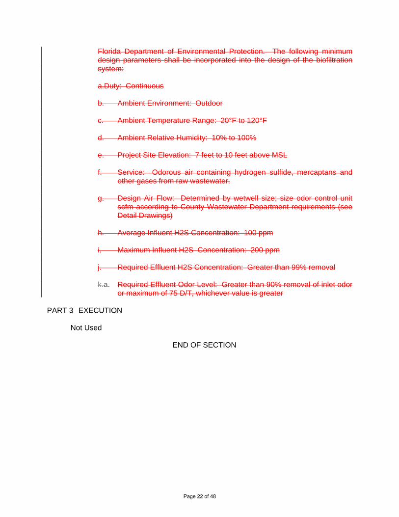
Florida Department of Environmental Protection. The following minimum design parameters shall be incorporated into the design of the biofiltration system:
a.Duty: Continuous b. Ambient Environment: Outdoor c. Ambient Temperature Range: 20°F to 120°F d. Ambient Relative Humidity: 10% to 100% e. Project Site Elevation: 7 feet to 10 feet above MSL f. Service: Odorous air containing hydrogen sulfide, mercaptans and
other gases from raw wastewater. g. Design Air Flow: Determined by wetwell size; size odor control unit
scfm according to County Wastewater Department requirements (see Detail Drawings)
h. Average Influent H2S Concentration: 100 ppm i. Maximum Influent H2S Concentration: 200 ppm j. Required Effluent H2S Concentration: Greater than 99% removal k.a. Required Effluent Odor Level: Greater than 90% removal of inlet odor
or maximum of 75 D/T, whichever value is greater PART 3 EXECUTION Not Used
END OF SECTION
Page 22 of 48

Page 23 of 48

12" BERM WIDTH
2
10864
PIPESIZE
24
14
201816
"A" PIPESIZE
NOTE: ALL DIMENSIONS AREGIVEN IN INCHES.
SEE
TAB
LE
"A"
PASSING PIPE
PENETRATION SEALASSEMBLY WITH
STAINLESS STEELHARDWARE (SEE
COUNTY APPROVEDPRODUCT LIST,
APPENDIX F)
C6
1"
6"
AA
1/2" DIA. EXP.ANCHOREMBEDMENT 5" MIN.SS (TYP. OF 4)
1"x5/8" SLOTFOR 1/2"x2" 1/2"LG. SS BOLT,NUT AND LOCKWASHER (TYP.)
1" MIN TYPE IIPORTLANDCEMENT
SS PL 1/4" X 9 X -9"
SS BASE PLATE
1"x5/8" SLOT FOR 1/2"x 2" 1/2"LG. SS BOLT, NUT AND LOCK
WASHER (TYP.)
CL
C6x13 (TYP.)
L 2x2 SS
2 1/2"
6"
3"
5" 3"
DRILL HOLE ONLY (TYP.)
C L
IFT
STAT
ION
L
CENTER OF LIFT STATION WET WELL
L 2"x2"x1/4" SS
1 1/2" (TYP)
SECTION A-A
PLAN
TYPE II PORTLAND CEMENT
C LIFT STATIONL
1/2" DIA. SS U-BOLT
L 2" x 2" SS
SS PL 1/4" X 9" X 9"
1/4
1/2" DIA. EXP. ANCHORSS (TYP. OF 4)
LIFT STATIONPUMP DISCHARGE
1/2" DIA. EXP. ANCHOR SS(TYP. OF 4)
316 STAINLESSSTEEL PLATE
:RIGHT SUPPORT SHALL BE A MIRRORIMAGE OF DETAIL SHOWN
4
1412108
12 1628
18
262420
"A"
SUCTION AND VENT PIPE
Page 24 of 48
12'-0"
#4 DOWELS @ 12" C/C X:
1'-0
"
GENERATOR (SLAB/REINF.)
8"
(3)#4CONT. 1
1
#4 @ 12" O/C, EW,TOP & BOTTOM
1'-6
"
T.O. CONC100 YEARFLOOD EL.
NOTE: CONTRACTOR SHALL PROVIDE A 3/8" CLOSEDCELL NEOPRENE PAD ON THE SLAB TO MATCH THE BASEFOOTPRINT OF THE GENERATOR OR THE DIESEL PUMP.
6'-0
"
8" GRANULAR, FREE DRAINING SANDUNDER SLAB, COMPACTED TO (98%MODIFIED PROCTOR) ASTM D1557
11
1'-6
"
8"
8"
#5@12" O/C, EW,MID-DEPTH
#5@12" O/C, EW
BROOM FINISH
6" FREE-DRAINING,CLEAN GRANULAR
MATERIALCOMPACT SUBGRADE TO ADENSITY OF 95% PER ASTMD-1557 (MODIFIED PROCTOR)
1"132"
SLOPED CONCRETEEQUIPMENT PAD
11'-0"
1. ALL CONCRETE SHALL BE 4000 PSI MINIMUM COMPRESSIVE STRENGTH; W/C = 0.45,AIR CONTENT 6% (±) 1%; SLUMP = 4" BEFORE ADDING WATER REDUCING AGENT.
2. ALL STEEL SHALL BE ASTM A615, GR 60.
3. ALL DIMENSIONS SHOWN ARE TYPICAL ONLY. CONTRACTOR TO VERIFY OVERALLSLAB SIZE WITH EQUIPMENT MANUFACTURER AND ENGINEER PRIOR TOCONSTRUCTION.
4. ALL SLABS SHALL HAVE TOOLED EDGES ON ALL SIDES
8'-0
"
FIN GR.
#5 AT 12" EW, CENTER
6'-0"
4'-0
"
6"
T.O. CONC100 YEARFLOOD EL.
T.O. CONC100 YEARFLOOD EL
2" T
O 6
"
3/8" NEOPRENE PAD
Page 25 of 48

EDCBAPIPE
301817
1
1
1
1
7
7
7
7
7 1
4 3/163
4 13/16
5 7/16
8 7/16
6 15/16
3
3
3
3
4
5
6
10
8
* ALL DIMENSIONS IN INCHES.
312 9 15/16
MINSIZE MAX
STEEL PLATE1/2" 316 SS THICK SQUARE
1/4"
B
A
C
PROCESS PIPE
1" NON-SHRINK GROUT
(TYP OF 4)LEVELING NUTSANCHORS WITH5/8" 316 SST WEDGE
GRADE (DIMENSION "E")REQUIRED PIPEPIPE CUT TO MEETSCHEDULE 40 316 SS
1/4" NEOPRENE PAD
316 SST U-BOLT
NOTES:
1. PIPE SUPPORT HEIGHT TO BE ADJUSTABLE.
2. SEE PLANS AND SECTIONS FOR PIPE GRADEREQUIREMENT (DIMENSION "E").
3. PIPE SUPPORT TO BE COMPATIBLE WITH HDPE PIPE.
4. ALL MATERIALS AND HARDWARE TO BE 316 SS.CONSTRUCT 18" x 18" x 6" CONC BASE WITH # 4REINFORCING STEEL @ 5" OCEW IF SUPPORT ISNOT LOCATED ON AN EXISTING SLAB.
STANCHION 316 SSSADDLE
3018
3018
3018
3018
3018
E
D
MAX. 1" SPACE
BOTTOM TENSION WIRE
VINYL COATED2" LINE POST SCH. 40GALV. STEEL PIPE (TYP.)
6 GA. WIRE TIES 14" MAX.SPACING TYP.
VINYL COATEDTENSION BAR3/16"x3/4" GALV.STEEL (TYP.)
VINYL COATED2-1/2" SCH 40 GALV.
STEEL PIPECORNER (TYP.)
NOTE:ALL FENCING SHALL BE PER SPECIFICATIONSAND SHALL BE BLACK VINYL COATED W/
BLACK PRIVACY SLATS
SLATSDETAILNOTE:COLOR OF THE SLATS SHALL BEBLACK.
8' MAX SPACING
3'-4
"
12" TYP.
3'M
AX.
6'
3'
NOTE:CONTRACTOR TO HANDDIG IF UTILITIES ARE ORMAY BE IN CONFLICTWITH POSTS
TURNBUCKLE(3" TAKEUP)
TRUSS ROD
HAND DIG IFCONFLICT WITH
UTILITIES
VINYL COATEDTENSION BAR3/16"x3/4" GALV.STEEL (TYP.)
2" Ø GATEFRAME TYP.
VINYL COATED2-1/2" SCH. 40GATE POSTBAR
BANDS
BLACKVINYL
COATED(TYP)
6"
1'-6
"
12"
3'-4
"
3'-0
"
6'
3'M
AX.
Page 26 of 48
xxxxxxxxxxxxxx
xxxx
xxxx
xxxx
xxxx
xxxx
xxxx
xxxx
xxxx xx xx xx xx xx xx xx xx xx xx xx xx xx xx xx xx
xxxx
xxxx
xxxx
xxxx
xxxx
xxxx
xxxx
xx
xxxxxxxxxxxxxxxxxx
Page 27 of 48

xxxxxxxxxxxxxx
xxxx
xxxx
xxxx
xxxx
xxxx
xxxx
xxxx
xxxx xx xx xx xx xx xx xx xx xx xx xx xx xx xx xx xx
xxxx
xxxx
xxxx
xxxx
xxxx
xxxx
xxxx
xx
xxxxxxxxxxxxxxxxxx
Page 28 of 48
xxxxxxxxxxxxxx
xxxx
xxxx
xxxx
xxxx
xxxx
xxxx
xxxx
xxxx xx xx xx xx xx xx xx xx xx xx xx xx xx xx xx xx
xxxx
xxxx
xxxx
xxxx
xxxx
xxxx
xxxx
xx
xxxxxxxxxxxxxxxxxx
Page 29 of 48
PUMP STATION CONTROL PANEL DETAIL - FRONT ELEVATIONSCALE: 1" = 4'-0"
PUMP STATION CONTROL PANEL DETAIL - BACK ELEVATIONSCALE: 1" = 4'-0"
PUMP STATION CONTROL PANEL DETAIL - PLAN VIEWSCALE: 1" = 4'-0"
TO GROUNDING LOOP
TO GROUNDING LOOP
Page 30 of 48

T0 GROUNDINGLOOP
Page 31 of 48

GROUND ROD MINIMUM TWO,SEE GROUND TEST WELLDETAIL WW-9C
Page 32 of 48
FENCE POST/GATE BONDING DETAILNOT TO SCALE
CONCRETEFOUNDATION
MASONRY ANCHOR
GROUND CLAMP
FINISH GRADE
FENCE POST
#2 SOLID TINNEDCOPPERJUMPER CABLE,GREEN INSULATIONTYPICAL FOR BOTHSIDES OF GATES.
TOGROUND
ROD
GATEFRAME
GROUNDCLAMP
#2 SOLID TINNEDCOPPER GROUNDCONDUCTOR
GATEPOST
3/4"x20'COPPER-CLADGROUND ROD
GROUND TEST WELL DETAILNOT TO SCALE
24" M
IN.
FINISHED GRADE
MATCH SITE STONE
#4/0 BARE COPPERGROUND CABLE (TYP.)
3/4"x20' COPPER-CLADGROUND ROD
EXOTHERMICALLYCONNECT
3" M
IN.
12" M
IN.
COMPACTED BACKFILL
TO COUNTERPOISETO SERVICE RATEDDISCONNECT
GROUND MAT DETAILNOT TO SCALE
BUS LUGSEQUIP. GROUND
#4/0 BARECOPPER (TYP.)
(TYP. OF 4)TO COUNTERPOISE3/4"X20' COPPER-CLAD
GROUND ROD, SEE GROUNDROD TEST WELL DETAIL
NOTES:1. ADDITIONAL CONCENTRIC RINGS SHALL BE ADDED
AS REQUIRED TO MEET THE FIVE (5) OHM (OR LESS)SPECIFIED RESISTANCE. EACH RING TO HAVE FOUR(4) GROUND RODS MIN. AND SPACED TEN (10) FEETFROM THE INNER RING.
18"9.5"
22" 13.5"
12"
CAST IRON TRAFFICCOVER MARKED"GROUND"
OLD CASTLECONCRETE BOXSERIES MB37
Page 33 of 48
C
M
C
#4/0 BARE COPPER(TYP. OF 2)
#4/0 BARE COPPER(TYP. OF 2)
SEE GROUND TESTWELL DETAIL WW-19B
#4/0 BARE COPPER TOGROUND MAT (TYP)
PANELBOARD
NOTES
1. BOND FENCE AND VEHICLE ACCESS GATE TO COUNTERPOISE.
2. PROVIDE LIGHTNING PROTECTION FOR SCADA ANTENNA.
3. SURGE PROTECTION SHALL BE SQUARE D (THREE PHASE:#SDSA3650) WITH LED LIGHTS AND MOUNTED IN A FASHION THATTHE PHASE LIGHTS ARE VISIBLE. COORDINATE EXACT LOCATIONWITH OWNER.
4. EXOTHERMICALLY BOND GROUNDING JUMPERS TO COUNTERPOISE.GROUND POTENTIAL SHALL BE CONSISTENT FOR ENTIRE SITE.GROUNDING JUMPERS AND COUNTERPOISE SHALL BE #4/0 BARECOPPER. GROUND RODS SHALL BE 3/4" X 20' COPPER-CLAD GROUNDRODS. EXOTHERMICALLY WELD CONNECTIONS BELOW GRADE.MECHANICALLY CONNECT CONNECTIONS ABOVE GRADE.MECHANICAL LUGS SHALL ONLY HAVE ONE WIRE LANDED IN EACHTERMINATION. EACH LUG SHALL BE FASTENED WITH A STAINLESSSTEEL NUT AND BOLT. STACKING OF INDIVIDUAL LUGS WILL NOT BE
ACCEPTABLE. GROUND BOXESSHALL BE 14" LONG QUAZITE#PC1118CA0017 OR #PG1118BA12,INSTALL LEVEL WITH THEADJACENT GROUND, PROVIDE 57STONE OR MATCH SITE STONE INBOX, WITH GROUND ROD LOCATEDOFF CENTER OF BOX. QUAZITEBOX COVER TO READ "GROUND".EXPOSED GROUNDING SHALL BEIN 1" SCHEDULE 80 PVC OR LIQUIDTIGHT FLEXIBLE CONDUIT.
5. PROVIDE COUNTY SIGNEDINSPECTION OR PHOTO OF ALLCAD-WELDED SPLICES ANDUNDERGROUND TAPS. PROVIDEGROUND TEST REPORT TOCOUNTY VERIFYINGCOUNTERPOISE RESISTANCE ISLESS THAN 5 OHMS.
Page 34 of 48
CONTROLPANEL
DIESELBACKUP
PUMPCONTROL
PANELBOARD
C
SEE GROUND TESTWELL DETAIL WW-19B
#4/0 BARE COPPER(TYP. OF 2)
M
C
#4/0 BARE COPPER TOGROUND MAT (TYP)
#4/0 BARE COPPER(TYP. OF 2)
MOTORJ-BOX
NOTES
1. BOND FENCE AND ACCESS GATE TO COUNTERPOISE.
2. PROVIDE LIGHTNING PROTECTION FOR SCADA ANTENNA.
3. SURGE PROTECTION SHALL BE SQUARE D (THREE PHASE:#SDSA3650) WITH LED LIGHTS AND MOUNTED IN A FASHION THATTHE PHASE LIGHTS ARE VISIBLE. COORDINATE EXACT LOCATIONWITH OWNER.
4. EXOTHERMICALLY BOND GROUNDING JUMPERS TO COUNTERPOISE.GROUND POTENTIAL SHALL BE CONSISTENT FOR ENTIRE SITE.GROUNDING JUMPERS AND COUNTERPOISE SHALL BE #4/0 BARECOPPER. GROUND RODS SHALL BE 3/4" X 20' COPPER-CLAD GROUNDRODS. EXOTHERMICALLY WELD CONNECTIONS BELOW GRADE.MECHANICALLY CONNECT CONNECTIONS ABOVE GRADE.MECHANICAL LUGS SHALL ONLY HAVE ONE WIRE LANDED IN EACHTERMINATION. EACH LUG SHALL BE FASTENED WITH A STAINLESSSTEEL NUT AND BOLT. STACKING OF INDIVIDUAL LUGS WILL NOT BE
ACCEPTABLE. GROUND BOXES SHALLBE 14" LONG QUAZITE #PC1118CA0017OR #PG1118BA12, INSTALL LEVEL WITHTHE ADJACENT GROUND, PROVIDE 57STONE OR MATCH SITE STONE IN BOX,WITH GROUND ROD LOCATED OFFCENTER OF BOX. QUAZITE BOX COVERTO READ "GROUND". EXPOSEDGROUNDING SHALL BE IN 1"SCHEDULE 80 PVC OR LIQUID TIGHTFLEXIBLE CONDUIT.
5. PROVIDE COUNTY SIGNEDINSPECTION OR PHOTO OF ALLCAD-WELDED SPLICES ANDUNDERGROUND TAPS. PROVIDEGROUND TEST REPORT TO COUNTYVERIFYING COUNTERPOISERESISTANCE IS LESS THAN 5 OHMS.
Page 35 of 48
Item 4
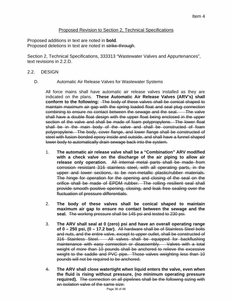
Proposed Revision to Section 2, Technical Specifications Proposed additions in text are noted in bold. Proposed deletions in text are noted in strike-through. Section 2, Technical Specifications, 333313 “Wastewater Valves and Appurtenances”, text revisions in 2.2.D. 2.2. DESIGN
D. Automatic Air Release Valves for Wastewater Systems
All force mains shall have automatic air release valves installed as they are indicated on the plans. These Automatic Air Release Valves (ARV’s) shall conform to the following: The body of these valves shall be conical shaped to maintain maximum air gap with the spring loaded float and seal plug connection combining to ensure no contact between the sewage and the seal. The valve shall have a double float design with the upper float being enclosed in the upper section of the valve and shall be made of foam polypropylene. The lower float shall be in the main body of the valve and shall be constructed of foam polypropylene. The body, cover flange, and lower flange shall be constructed of steel with fusion-bonded epoxy inside and outside, and shall have a funnel shaped lower body to automatically drain sewage back into the system. 1. The automatic air release valve shall be a “Combination” ARV modified
with a check valve on the discharge of the air piping to allow air release only operation. All internal metal parts shall be made from corrosion resistant 316 stainless steel, with all operating parts, in the upper and lower sections, to be non-metallic plastic/rubber materials. The hinge for operation for the opening and closing of the seal on the orifice shall be made of EPDM rubber. The rolling resilient seal shall provide smooth positive opening, closing, and leak free sealing over the fluctuation of pressure differentials.
2. The body of these valves shall be conical shaped to maintain
maximum air gap to ensure no contact between the sewage and the seal. The working pressure shall be 145 psi and tested to 230 psi.
3. The ARV shall seal at 0 (zero) psi and have an overall operating range
of 0 – 250 psi, (0 – 17.2 bar). All hardware shall be of Stainless Steel bolts and nuts, and the entire valve, except to upper outlet, shall be constructed of 316 Stainless Steel. All valves shall be equipped for backflushing maintenance with easy connection or disassembly. Valves with a total weight of more than 10 pounds shall be anchored to relieve the excessive weight to the saddle and PVC pipe. Those valves weighting less than 10 pounds will not be required to be anchored.
4. The ARV shall close watertight when liquid enters the valve, even when
the fluid is rising without pressure, (no minimum operating pressure required). The connection on all pipelines shall be the following sizing with an isolation valve of the same size:
Page 36 of 48

Item 4
8-inch and smaller 2-inch threaded
10-inch through 16-inch 3-inch flange/threaded 18-inch and larger 4-inch flange/threaded
5. The working pressure shall be 250 psi (17.2 bar) and tested to 360 psi (25 bar). All automatic air release valves shall be ARI model S-025. All valves shall be installed in accordance with manufacturer recommendations and shall have an isolation valve connection for control. All air release valves shall have ISO 9002 certification in order to be supplied on this project.
6. The ARV shall include both a Polypropylene Debris Shield funnel and an Orifice Strainer to prevent solids from entering sealing area.
7. The ARV shall have a rolling cup seal diaphragm for infinitely variable
operation, providing water hammer inhibition.
8. The ARV body shall be constructed of 316 stainless steel. The float shall be Delrin (Polyoximethylene, POM), the Float Spindle shall be of 316 stainless steel. The valve seat and all internal working parts shall be of corrosion –resistant materials. ARV flange hardware (nuts, bolts, washers) shall be of 316 Stainless Steel construction.
9. The threaded or flanged outlet size of the ARVs shall be sized by the
design engineer. A minimum diameter of 2-inches shall be provided.
10. All parts required for ARV maintenance shall be the same for all connection sizes. (ie: the internal parts for the 2” ARV are identical to the internal parts for the 4” ARV).
11. All automatic air release valves shall be 316 stainless steel body, and
the manufacturer and model shall comply with the County Approved Product List (Appendix F). All valves shall be installed in accordance with manufacturer recommendations and shall have an isolation valve connection for control.
12. All automatic air release valves installed for wastewater
transmission systems (except at pump stations or wastewater treatment facilities) shall be installed in above ground polyethylene enclosures as shown on the County’s standard details. Color of enclosures shall be dark green.
Page 37 of 48

Page 38 of 48

Page 39 of 48

Page 40 of 48

Item 5
Proposed Revision to Section 2, Technical Specifications Proposed additions in text are noted in bold. Proposed deletions in text are noted in strike-through. Section 2, Technical Specifications, 333913 “Sewer Manholes”, text revisions in 3.1.F. 3.1 INSTALLATION
F. Internal Protection: Provide internal protection for all manholes by either of the following:
1. Sewpercoat, calcium-aluminate mortar blend coating system, or
2. IET Coating system – surface preparation shall include pressure washing at
5,000 psi, dry abrasive blasting with black beauty steel slag and application of the IET coat at three (3) different intervals to a total thickness of 125 mils, or
3. Raven Lining Systems
Install the coating systems per manufacturer’s recommendation and completely protect the structure from corrosion. The liner or coating systems must extend and seal onto manhole ring, seal onto and around pipe openings, and any other protrusions, completely cover the bench and flow invert. Provide a five (5)-year unlimited warranty on all workmanship and products. The work includes the surface preparation and application of the coating or liner system, and shall protect the structure for at least five (5) years from all leaks and from failure due to corrosion from exposure to corrosive gases such as hydrogen sulfide. Repair internal coating of existing manholes cored during tie-in of new sewers by applying approved coating material as listed above in accordance with the manufacturer’s recommendations. If existing manhole has an internal coating other than that listed above (e.g. epoxy coating), sandblast the interior of the existing manhole and apply an approved coating in accordance with the manufacturer’s recommendations.
Page 41 of 48

Proposed Revision to Section 2, Technical Specifications Proposed additions in text are noted in bold. Proposed deletions in text are noted in strike-through. Section 2, Technical Specifications, 014500 “Quality Control”, Pages 4 and 5, text revisions in 1.5.A.4. 1.5 QUALITY CONTROL
A. Testing … 4. Testing of Gravity Sanitary Sewer Lines
a. Watertight Construction: It is imperative that all sewers and force
mains, manholes, and service connections be built watertight and that the CONTRACTOR adhere rigidly to the specifications for material and workmanship. Since all of the water and sewage in the lines will be treated at the treatment plant, special care and attention must be given to securing watertight construction. After completion, the sewers or sections thereof will be tested and gauged. If infiltration or exfiltration is above the limits specified, the sewer construction work will be rejected.
b. Cleaning: Exercise care during construction of the manhole to see
that materials do not enter the sewer line. Keep the invert and shelf of the manhole clean of all mortar, broken brick, sand, or any other materials falling into the manhole. Immediately remove such material. Maintain this condition until final acceptance of the work. Prior to testing of gravity sanitary sewer lines, clean the lines using appropriate tools.
c. Gravity Sewers - Visual Inspections: On completion of each block or
section of sewer, or at such other times as the County Manger or designee may direct, the block or section of sewer is to be cleaned, tested and inspected. Each section of the sewer is to show, on examination from either end, a full circle of light between manholes. Each manhole, or other appurtenance to the system, shall be of the specified size and form, be watertight, neatly and substantially constructed, with the rim set permanently to design position and grade. All repairs shown necessary by the inspection are to be made; broken or cracked pipe replaced, all deposits removed and the sewers left true to line and grade, entirely clean and ready for use.
d. Infiltration Limits: Provide the equipment necessary to check the lines
for infiltration or exfiltration as directed by the County Manager or designee, before they are put in service. Infiltration in excess of fifty (50) gallons per day inch-mile of sewer will result in having the CONTRACTOR go over the lines, ascertain where the leakage exists, and repair the lines to the extent necessary to bring the infiltration down within acceptable limits. Observable inflow is not permitted.
Page 42 of 48

e. Exfiltration Limits: The length of sewer subject to an exfiltration test
shall be the distance between two (2) adjacent manholes. Close the inlets of the upstream and downstream manholes with watertight plugs and the test section filled with water until the elevation of the water in the upstream manhole is two (2) feet above the crown of the pipe in the line being tested, or two (2) feet above the existing groundwater in the trench, whichever is higher. A standpipe may be used instead of the upstream manhole for providing the pressure head when approved by the County Manager or designee. Measure exfiltration by determining the amount of water required to maintain the initial water elevation for one (1) hour period from the start of the test. The maximum allowable leakage, including manholes, shall be 50 gallon per inch for diameter per mile of pipe per day.
f. Air Testing: Air testing shall be required if, in the opinion of the County
Manager or designee, conditions are such that infiltration measurements may be inconclusive. Conduct the test in the presence of the County Manager or designee and conform to the following requirements:
(a) Test pressure shall be 3.5 psi increased by the groundwater
pressure above the top of the sewer. (b) Pressure loss from shall not exceed 0.5 psi during the required
testing time. (c) Testing time in minutes shall be calculated as 0.625 x nominal
pipe size (inches).
g. Deformation Test
(a) Deformation tests shall be performed on all gravity sewer lines. The test shall be conducted after the final backfill has been in place at least 30 days to permit stabilization of the soil-pipe system.
(b) No pipe shall exceed a deformation of 5 percent. If deformation exceeds 5 percent, mechanical methods to correct deformation may be used. If mechanical methods are unsuccessful, the pipe shall be excavated. Replacement or correction shall be accomplished in accordance with requirements in the approved specifications.
(c) The rigid ball or mandrel used for the deflection test shall have a diameter not less than 95 percent of the base inside diameter or average inside diameter of the pipe depending on which is specified in the ASTM Specification, including the appendix, to which the pipe is manufactured. The test shall be performed without mechanical pulling devices.
Page 43 of 48
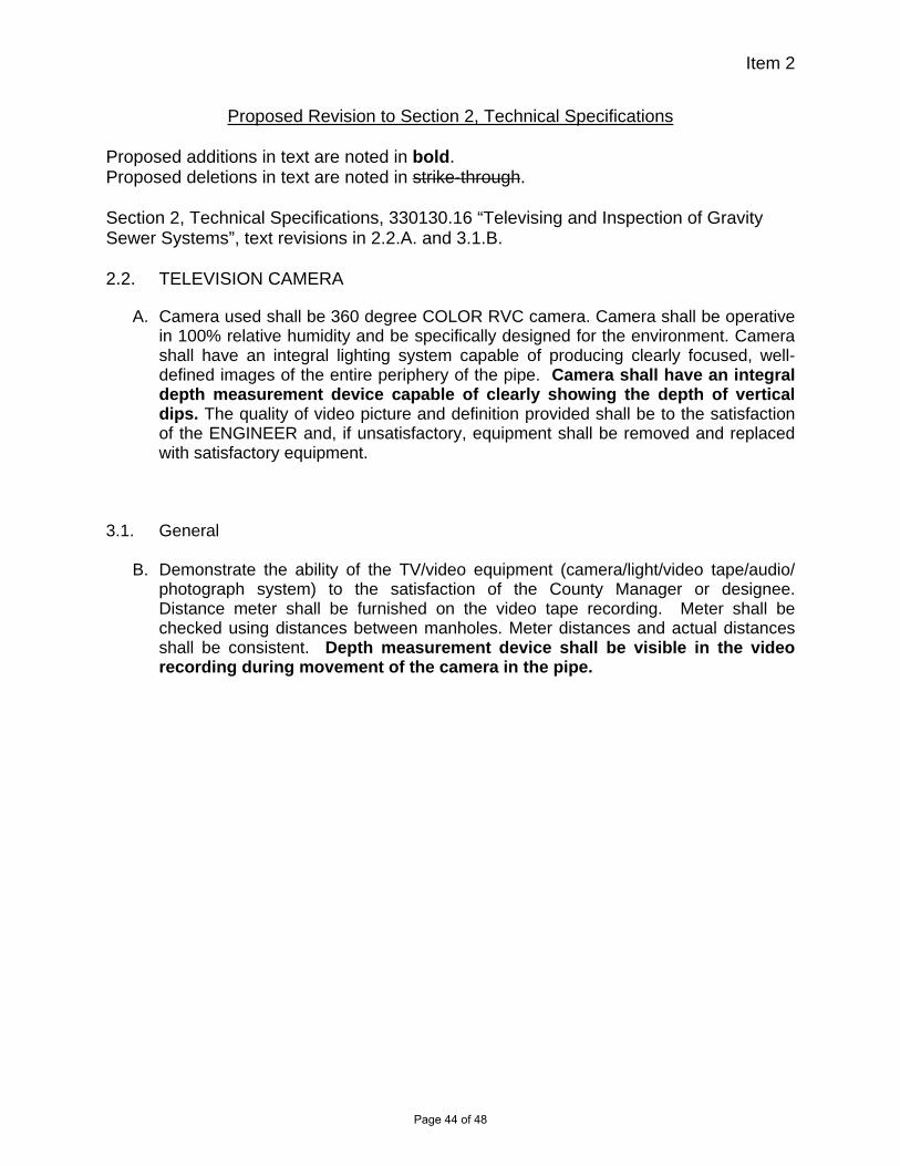
Item 2
Proposed Revision to Section 2, Technical Specifications Proposed additions in text are noted in bold. Proposed deletions in text are noted in strike-through. Section 2, Technical Specifications, 330130.16 “Televising and Inspection of Gravity Sewer Systems”, text revisions in 2.2.A. and 3.1.B. 2.2. TELEVISION CAMERA
A. Camera used shall be 360 degree COLOR RVC camera. Camera shall be operative in 100% relative humidity and be specifically designed for the environment. Camera shall have an integral lighting system capable of producing clearly focused, well-defined images of the entire periphery of the pipe. Camera shall have an integral depth measurement device capable of clearly showing the depth of vertical dips. The quality of video picture and definition provided shall be to the satisfaction of the ENGINEER and, if unsatisfactory, equipment shall be removed and replaced with satisfactory equipment.
3.1. General
B. Demonstrate the ability of the TV/video equipment (camera/light/video tape/audio/ photograph system) to the satisfaction of the County Manager or designee. Distance meter shall be furnished on the video tape recording. Meter shall be checked using distances between manholes. Meter distances and actual distances shall be consistent. Depth measurement device shall be visible in the video recording during movement of the camera in the pipe.
Page 44 of 48

Proposed Revision to Section 2, Technical Specifications Proposed additions in text are noted in bold. Proposed deletions in text are noted in strike-through. Section 2, Technical Specifications, 330518 “Laying and Jointing Buried Pipe”, Page 4, text revisions in 3.2.A. 3.2 INSTALLATION
A. General: Install all piping in accordance with the manufacturer’s recommendations and approved shop drawings and as specified in Division 1. Where pipe joint deflections are used, do not exceed 80 percent of the maximum deflection limits shown in AWWA C600. Gravity systems will shall contain no joint deflection. 1. Arrange miscellaneous pipelines, which are shown in diagram form on the Plans,
clear of other pipelines and equipment.
2. Gravity systems shall not contain vertical dips greater than one and a half inches (1.5”).
Page 45 of 48

Preparer's Information: Project Information: Date ====>
Name ============> Permit or AR Number
Title ==============> Name of Project ===>
Company=========> Project Address ===>
Address ==========>
Phone ============>
Email Address =====>
Please Note:
5. For remodeling projects this form must be submitted only if there is a net increase in Fixture Flow Value.
Demand Range (GPM) Meter Size
0 to 30 3/4"
30.1 to 50 1"
50.1 to 100 1 1/2"
100.1 to 160 2"
160.1 to 450 3"
450.1 to 1000 4"
Type or Print Name of Engineer/Architect of Record for Project
Signature of Engineer/Architect of Record for Project and Date
(If the meter is existing, Engineer/Architect must identify the meter manufacturer and model number)
Meter Size in Inches
[Affix Engineering/Architect Stamp Here]
1. All commercial facilities must be metered separately from residential facilities with the exception of those commercial facilities that are within a master metered residential development and designed for the exclusive use of the residents within such development.
3. Additional fees may apply if a backflow device is deemed necessary by the Water Distribution Department.
4. The Design Engineer/Architect must submit signed and sealed documentation supporting meter sizing. For meters 4-inch and smaller the sizing shall be based upon Fixture Flow Values as shown on the following page and sized as per the Table on page 3 unless approved otherwise by the Collier County Public Utilities Planning and
Project Management Department. For all meters the Engineer/Architect must consider all relevant factors before selecting the final meter size.
This Section to be filled out by Engineer/Architect of Record:
2. Meters that include fire service shall be selected to allow a maximum pressure loss at design flow of 5 psi except the 3-inch meter shall be a maximum pressure loss of 5.5 psi.
(Engineer/Architect must attach a completed Fixture Flow Value Worksheet)
Demand in accordance with the Fixture Flow Value Worksheet
and the Table for Estimating Demand
Water Meter Sizing FormOne Form Per Meter
Please call Public Utilities Engineering (239) 252-2583 with any questions.
Page 46 of 48
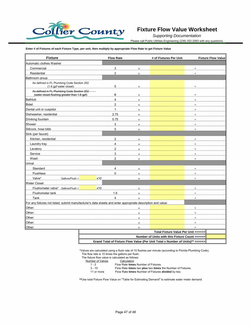
Flow Rate # of Fixtures Per Unit Fixture Flow Value
Automatic clothes Washer Commercial 3 x = Residential 2 x = Bathroom group
5 x =
6 x = 4 x = 2 x = 1 x =
2.75 x = 0.75 x =
3 x = 5 x =
2 x = 4 x = 2 x = 3 x = 2 x =
Standard 4 x = Flushless 0 x = Valve* Gallons/Flush = x10 x =
Water ClosetFlushometer valve* Gallons/Flush = x10 x = Flushometer tank 1.6 x = Tank 4 x =
For any fixtures not listed, submit manufacturer's data sheets and enter appropriate description and value:x = x = x = x = x =
Fixture Flow Value Worksheet
*Valves are calculated using a flush rate of 10 flushes per minute (according to Florida Plumbing Code). The flow rate is 10 times the gallons per flush. The fixture flow value is calculated as follows: Number of Valves Calculation 1 - 2 Flow Rate times Number of Fixtures. 3 - 10 Flow Rate times two plus two times the Number of Fixtures. 11 or more Flow Rate times Number of Fixtures divided by two.
Please call Public Utilities Engineering (239) 252-2583 with any questions.
Supporting Documentation
Enter # of Fixtures of each Fixture Type, per unit, then multiply by appropriate Flow Rate to get Fixture Value
Other:Other:Other:
**Use total Fixture Flow Value on "Table for Estimating Demand" to estimate water meter demand.
As defined in FL Plumbing Code Section 202 (1.6 gpf water closet)
As defined in FL Plumbing Code Section 202 (water closet flushing greater than 1.6 gpf)
Fixture
Total Fixture Value Per Unit =====>
Number of Units with this Fixture Count =====>
Grand Total of Fixture Flow Value (Per Unit Total x Number of Units)** =====>
Other:Other:
Bathtub
Laundry tray Kitchen, residentialSink (per faucet)
Service
Urinal Wash
Bidet
Lavatory
Dental unit or cuspidorDishwasher, residentialDrinking fountainShowerSillcock, hose bibb
Page 47 of 48

Load Demand Load Demand
Fixture Flow Value Gallons per minute Fixture Flow Value Gallons per minute1 3.0 --- ---2 5.0 --- ---3 6.5 --- ---4 8.0 --- ---5 9.4 5 15.06 10.7 6 17.47 11.8 7 19.88 12.8 8 22.29 13.7 9 24.6
10 14.6 10 27.011 15.4 11 27.812 16.0 12 28.613 16.5 13 29.414 17.0 14 30.215 17.5 15 31.016 18.0 16 31.817 18.4 17 32.618 18.8 18 33.419 19.2 19 34.220 19.6 20 35.025 21.5 25 38.030 23.3 30 42.035 24.9 35 44.040 26.3 40 46.045 27.7 45 48.050 29.1 50 50.060 32.0 60 54.070 35.0 70 58.080 38.0 80 61.290 41.0 90 64.3
100 43.5 100 67.5120 48.0 120 73.0140 52.5 140 77.0160 57.0 160 81.0180 61.0 180 85.5200 65.0 200 90.0225 70.0 225 95.5250 75.0 250 101.0275 80.0 275 104.5300 85.0 300 108.0400 105.0 400 127.0500 124.0 500 143.0750 170.0 750 177.0
1,000 208.0 1,000 208.01,250 239.0 1,250 239.01,500 269.0 1,500 269.01,750 297.0 1,750 297.02,000 325.0 2,000 325.02,500 380.0 2,500 380.03,000 433.0 3,000 433.04,000 535.0 4,000 535.05,000 593.0 5,000 593.0
SUPPLY SYSTEMS PREDOMINANTLY FOR FLUSH TANKSSUPPLY SYSTEMS PREDOMINANTLY FOR FLUSH
VALVES
Table for Estimating DemandSupporting Documentation
Please call Public Utilities Engineering (239) 252-2583 with any questions.
Page 48 of 48