Change history (this section will be removed once the ...cimug.ucaiug.org/Projects/IEEEmagCIM/Shared...
39
ARTICLE 5: CIM - UNDER THE HOOD Authors; Lars-Ola (LOO), Kurt (KH), Becky (BI), Kendall (KD), Margaret (MG), Tanja (TK), Alan (AM) Change history (this section will be removed once the document is finalized) Version 4 April 28, 2015 2015-05-07, TK: Accepted all changes, kept change tracking; comments to parts of document non-assigned to me started with “(note TK: ” – discuss the comment and then remove. I added below my figures what should look like a caption, but didn’t use any Word’s “insert caption” command until we confirm which figures are to keep. Continued editing after our web conference. 2015-05-16 version 5, LOO: Accepted all previous changes and merged texts from myself, Kurt and Kendall. 2015-05-26 version 6, BLI: Added text to separation of roles 2015-05-26 version 7 LOO: Accepted all changes. 2015-05-29 version 8 KDD: Added composition section details (more work to do but about right size.) Some minor text edits in the profiles section. No changes or comments outside these two sections. 2015-06-04 version 9 KLH: Added comments and made minor text corrections and clarifications. I’m concerned that this article goes deeper than is going to be useful for most readers without providing at least a basic understanding of the CIM UML model. I think we need to add a short section on the CIM UML with concrete examples and try to include the same concrete examples where ever possible throughout the article. 2015-07-06 version 10 LOO: Notes from 2015-07-06 meeting 2015-07-10 version 11 AMM: Updates by Alan 2015-07-12 version 12 LOO: Updates by Lars-Ola
Transcript of Change history (this section will be removed once the ...cimug.ucaiug.org/Projects/IEEEmagCIM/Shared...

ARTICLE 5: CIM - UNDER THE HOODAuthors; Lars-Ola (LOO), Kurt (KH), Becky (BI), Kendall (KD), Margaret (MG), Tanja (TK), Alan (AM)
Change history (this section will be removed once the document is finalized)Version 4 April 28, 2015
2015-05-07, TK: Accepted all changes, kept change tracking; comments to parts of document non-assigned to me started with “(note TK: ” – discuss the comment and then remove. I added below my figures what should look like a caption, but didn’t use any Word’s “insert caption” command until we confirm which figures are to keep. Continued editing after our web conference.
2015-05-16 version 5, LOO: Accepted all previous changes and merged texts from myself, Kurt and Kendall.
2015-05-26 version 6, BLI: Added text to separation of roles
2015-05-26 version 7 LOO: Accepted all changes.
2015-05-29 version 8 KDD: Added composition section details (more work to do but about right size.) Some minor text edits in the profiles section. No changes or comments outside these two sections.
2015-06-04 version 9 KLH: Added comments and made minor text corrections and clarifications.
I’m concerned that this article goes deeper than is going to be useful for most readers without providing at least a basic understanding of the CIM UML model. I think we need to add a short section on the CIM UML with concrete examples and try to include the same concrete examples where ever possible throughout the article.
2015-07-06 version 10 LOO: Notes from 2015-07-06 meeting
2015-07-10 version 11 AMM: Updates by Alan
2015-07-12 version 12 LOO: Updates by Lars-Ola
2015-07-13 version 13 LOO: Comments added by Chavdar, changes accepted and after that removal of comments.
2015-07-14 version 14 TK: Cleaned up a little bit, accepted some deletions where nothing left to do, corrected a couple of typos, inserted TOC (should help find the “red line”), touched original chapter 2 (now called Setting the stage), added some comments or replied to Chavdar’s (right bar in Word), added two figures in the profile serialisation section.
2015-07-08 version 15 LOO: Went through an accepted deletions I think we agree on. Did adjustments according to comments. Added a little more on the network model evolution since CPSM. Added back a

hopefully better discussion on node-breaker and bus-branch models and the implications on serialization formats. Shrunk intro to the interop section. Added discussion on node-breaker and bus-branch models in examples section.

Contents (Delete this section for final document)Change history.............................................................................................................................................1
The big picture.............................................................................................................................................3
Scope statement; LOO.............................................................................................................................3
Setting the stage..........................................................................................................................................3
Interoperability............................................................................................................................................4
Overview.................................................................................................................................................4
Data structuring / schema / semantic model..........................................................................................5
Data partitioning......................................................................................................................................6
The canonical model....................................................................................................................................7
UML and basic rules of CIM canonical model..........................................................................................7
Local non-(IEC)standard extension..........................................................................................................7
CIM profiles for data exchanges..................................................................................................................7
Overview.................................................................................................................................................7
Examples.................................................................................................................................................8
How IEC uses CIM profiling....................................................................................................................11
Payload serialization level.........................................................................................................................13
Messaging and the 61968-100 WS and XSD structures.............................................................................15
Anatomy of an interface........................................................................................................................15
Data composition by receiving systems.....................................................................................................17
Conclusions................................................................................................................................................21
Definitions.................................................................................................................................................21
Further Readings.......................................................................................................................................22
Authors......................................................................................................................................................22
The big pictureScope statement; LOOThis article provides an overview of CIM based data exchanges, how they are created and how they may be implemented within the enterprise or between utility entities. The primary purpose is to explain how the CIM can be used to generate exchange packages and how those packages enable an integration framework. Using the Common Information Model (CIM) as a basis for all exchange payloads ensures the exchange content is clearly defined in a standard way and the data is interpreted the same across different business domains.
Primarily about (related) exchange governance. Each payload is typically not simply related to itself.
Tailoring local related exchanges
Setting the stageEarly History – Transmission Data ExchangeHistorically, the initial CIM canonical model was created to allow EMS-to-EMS import and export of network models and to remove the proprietary data formats that prevented data exchange between EMS systems. However, it was discovered almost immediately that this model could also be used to exchange power system data used in network analysis such as power flows, topology processing, state estimation, etc. These subsets of data became known as profiles (see “CIM Profiles for Data Exchanges” for more information). NERC was the first to suggest a profile that contained sufficient data to solve a power flow. This profile would be used by the utilities and interconnections to generate more accurate models and ensure grid reliability. To assist in this, NERC defined the generic data requirements to solve a Power Flow. This resulted in the first profile known as the Common Power System Model (CPSM) profile. and its first profile (with “profile” meaning a subset of the CIM canonical model), at that time called “CPSM (Common Power System Model) profile the based on requirements defined by NERC”, were created to allow for an EMS intra-application exchange of power system model data, such as typically used in network analysis (state estimation, topology processing, power flow, security analysis), as well as EMS-to-EMS import and export of network model snapshots.
Once the data content of the profile was defined, the next step was to define the data format that would be used within the data file itself. The canonical CIM supports both detailed node-breaker and bus-branch models for network analysis applications. However, tThe CPSM profile was intended for use in operational systems (EMS) and hence supports node-breaker models with detailed substations including breakers, disconnectors, measurements, equipment structures within substations etc. This is

different from bus-branch models intended for power flow applications where all substation details has been replaced by power flow busses.
Node-breaker models haves many more object types (e.g. Breakers, Disconnectors, Measurements, VoltageLevels etc.) and relationships between them than a bus-branch model. Representing these relationships in exchange documents can made by references (pointers) or by inclusion of the referenced data at the place of the reference. Documents based on XML Schema can include referenced data by hierarchical nesting. , tThis was the only way to support references in XML Schema when CPSM was created. Hierarchical nesting of references has drawbacks; the same data may be referenced multiple times resulting in duplication or, the data is not available and is described in another document. As a result, it was decided to use a modified version of the RDF schema in an XML exchange format. This would satisfy all the industry requirements for the data exchange format and remove the drawbacks imposed by XML Schema. Hence, the CIMXML exchange format described in the (IEC 61970-552 standard ) was created where all relationships are expressed as references.
The CPSM profile has since evolved into an extensive standard supporting many network analysis applications as well as network related data such as locations and schematic diagrams, e.g. the ENTSO-E CIM standard for Common Grid Model Exchange Standard (CGMES).
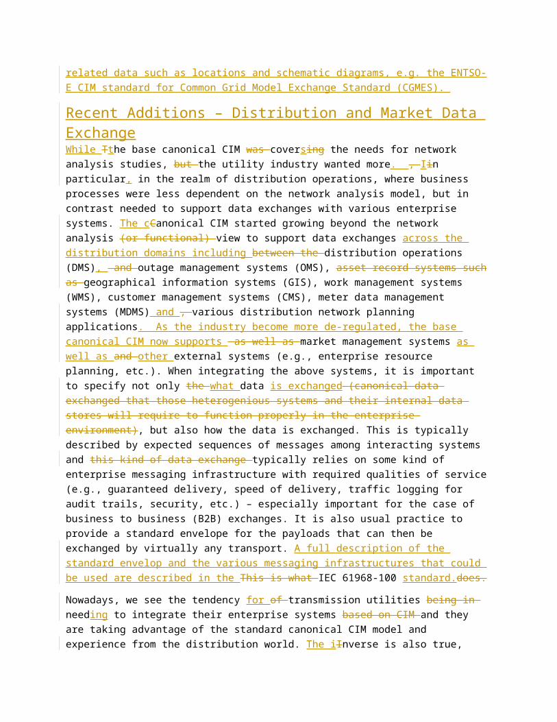
Recent Additions – Distribution and Market Data ExchangeWhile Tthe base canonical CIM was coversing the needs for network analysis studies, but the utility industry wanted more. , Iin particular, in the realm of distribution operations, where business processes were less dependent on the network analysis model, but in contrast needed to support data exchanges with various enterprise systems. The cCanonical CIM started growing beyond the network analysis (or functional) view to support data exchanges across the distribution domains including between the distribution operations (DMS), and outage management systems (OMS), asset record systems such as geographical information systems (GIS), work management systems (WMS), customer management systems (CMS), meter data management systems (MDMS) and , various distribution network planning applications. As the industry become more de-regulated, the base canonical CIM now supports as well as market management systems as well as and other external systems (e.g., enterprise resource planning, etc.). When integrating the above systems, it is important to specify not only the what data is exchanged (canonical data exchanged that those heterogenious systems and their internal data stores will require to function properly in the enterprise environment), but also how the data is exchanged. This is typically described by expected sequences of messages among interacting systems and this kind of data exchange typically relies on some kind of enterprise messaging infrastructure with required qualities of service (e.g., guaranteed delivery, speed of delivery, traffic logging for audit trails, security, etc.) – especially important for the case of business to business (B2B) exchanges. It is also usual practice to provide a standard envelope for the payloads that can then be exchanged by virtually any transport. A full description of the standard envelop and the various messaging infrastructures that could be used are described in the This is what IEC 61968-100 standard.does.
Nowadays, we see the tendency for of transmission utilities being in needing to integrate their enterprise systems based on CIM and they are taking advantage of the standard canonical CIM model and experience from the distribution world. The iInverse is also true, i.e., larger distribution utilities see
the advantage in leveraging distribution network models within many of their business processes and they are actually taking advantage of the canonical CIM model and experience from the transmission world.
The following sections will show how the canonical the set of standards around CIM and profiling techniques can be used to define cover a big number of needs for data exchanges and provide a framework to integrate various enterprise systems in the electrical industry. utilities and markets, from networks modelling for power flow kind of studies, to dynamics, to operations and planning, to smart metering, to unique identification of real world entities, to integration with various enterprise systems – to name a few. During the formation of energy markets within the North American region, the need to standardize market exchanges became apparent. At this time, a committee of Regional Transmission Owners was formed to address the definition of the energy market supplemental model data and market communications for the North American markets. These use cases were developed as the market operation extensions which are now contained within CIM.
The European Network of Transmission System Operators for Electricity (ENTSO-E) was being formed in 2009. Besides all the tasks defined in the European legislation ENTSO-E supported the integration of member Transmission System Operator’s (TSO) business requirements and use cases into the CIM.
InteroperabilityOverviewThe CIM standard was already from its early beginning in 1994 intended to enable interoperability. Originally it was interoperability between applications that has been widened to interoperability between systems. Another widening was from applications for network analysis to work processes within a utility and energy markets as mentioned above. The network analysis has also grown from power flow type of applications to short circuit analysis, dynamics analysis etc. Yet another widening is support for network display layout, geographical locations, assets information, asset health etc.
This widening is still ongoing and extensions are still added. In EU the consequence of the common energy market, increased renewable production and reduction of CO2 emissions resulted in accelerated use of CIM. When ENTSO-E started to use the CIM in its Common Grid Model Exchange Standard (CGMES), needs to further extend the CIM were discovered.
The central architectural idea behind CIM is to describe data semantics such that exchanged data objects can be traced back to the canonical CIM semantics. CIM supports this by is its capability to describe relations between objects, e.g.
Equipment in the functional model (PowerSystemResurce CIM class) relate to physical equipment in the asset model (Asset CIM class). This makes it possible to answer a question like; what is the serial number and actual short circuit current (asset model) of the breaker I am currently using in position Q1 (functional model) in my substation?
Registered resources in the market model relate to generating units in the functional model. This is useful when a production schedule from the market is validated with Congestion Forecast (e.g. in intra-day CF / day-ahead CF) or used in a Security Constrained Unit Commitment (SCUC).

These are just a few examples of many relations between the different parts of the CIM. Relations like this enable cross navigation between data exchanged according to different profiles. Two use cases building on the above examples are
A Supervisory Control and Data Acquisition (SCADA) system typically records how many times a breaker operates. Knowing which breaker in the asset registry is used in the circuit monitored by SCADA can then be used to tell the asset registry how many times the breaker has been operated. This is needed to determine breaker wear.
A market system typically deals with net production from registered units at plant level. Knowing what functional generating units corresponds to a registered unit makes it possible to map registered unit net production schedules on functional unit gross production also considering outages and de-ratings. This mapping is needed for Congestion Forecast (CF) and Security Constrained Unit Commitment (SCUC).
Relations between objects require a concise global identification mechanism such that objects are uniquely referenced and not mixed with each other. Human generated names have the drawback that different objects are likely to have the same name, e.g. the substation name “Airport” may exist in many places. Additionally names may need to change over time, but unique identification must be persistent. Hierarchical naming is a usual way to get more precision as with postal addresses, internet addresses etc. But naming schemes like this require authority support and administration for its maintenance. In CIM, the Master Resource ID (mRID) identification scheme is recommended to be used for object identification, for more details see below.
When extending CIM it is important to have use cases such as those mentioned above in mind such that the relations are added to support navigation across profiles. The relations like this need to be present in the CIM canonical model to facilitate cross navigation between profiles. Hence a good modelling practice is to make sure that data shared by different profiles are described in the canonical CIM. The description shall also be precise with clear semantics to avoid that the same data item is used to mean different things in different profiles. Unclear description of a CIM class, attribute or relation has resulted in investigations to figure out the semantics over the past years. So spending time in creating good descriptions make it easier for future users to use the model correctly and avoid duplicate use for different things. Another benefit by being specific is that data that may look the same actually are different when reading the description for the data.
As mentioned above CIM has grown considerably since its creation. This has resulted in a reputation that CIM is continuously changing which is actually true with respect to all extensions. The early parts however have been stable, in particular in recent years. When a new model is added to the CIM it hasn’t typically been implemented yet. As implementations appear issues are normally discovered and corrections are needed. Hence newer parts of the CIM are initially less stable but as interoperability tests aiming at vetting of CIM standards are conducted and usage increases, the model stabilizes. As the usage of CIM has increased the standardization work has also become much more careful in making extensions such that the impact on existing implementations is minimized.

Data structuring / schema / semantic modelThe CIM canonical model (see The canonical model) includes a very large number of classes and each class has associations describing relationships with other classes. Most classes also have attributes describing characteristics of the class. Any given work flow or data exchange will use only a fraction of the classes, associations and attributes defined in the CIM. Profiles (see CIM profiles for data exchanges) are defined to specify the specific subset of classes, associations and attributes from the CIM that are used for a particular data exchange.
Because the information included in a profile is based on the CIM canonical model the meaning of the information is clearly understood. For instance, any profile that includes the class and attribute defining the resistance of an AC transmission line (attribute “r” of the “ACLineSegment” class) will have the same understanding of the data being exchanged.
The CIM UML model uses a type system that also helps to ensure a clear understanding of the attributes. CIM data types are defined for common electrical quantities such as “ActivePower,” “AngleRadians,” “Resistance,” and “Susceptance.” For instance, attribute “r” of the “ACLineSegment” class uses the CIM data type “Resistance”.
In most cases a data exchange will need to reference data objects previously exchanged. For instance the results of a power flow will reference the individual pieces of equipment from a network model that was previously exchanged. When changes are made to a network model an incremental update can be exchanged that will reference the objects that have been added, modified or deleted.
Data objects that may need to be referenced have to be kept persistent by the receiver of the data and they must have unique, persistent identification. In CIM the class IdentifiedObject has been defined specifically as a superclass for any class that needs to be persistent after it is initially exchanged. The master resource identifier attribute, “mRID,” of IdentifiedObject is included in the CIM to provide a common method for persistent, unique identification. When used in a data exchange the “mRID” is required to be unique within the context of the exchange. Global uniqueness is achieved by using a Universally Unique Identifiers (UUIDs), which is strongly recommended, but not required.
In an ideal data exchange UUIDs would be used as the mRIDs to uniquely identify all objects, but this cannot always be achieved when working with existing applications that already have other established methods of unique identification. In this case CIM naming attributes and classes such as the “name” attribute on “IdentifiedObject” or the alternate name classes “Name,” “NameType,” and “NameTypeAuthority” can be leveraged.
Data partitioning Network model data documents representing large interconnected power networks may become large. This is dealt with by partitioning documents in two ways
Documents with different types of data described by different CIM Profiles. Documents with parts of instance data from different Model Authorities.
As described in the “Data structuring” section CIM data is divided into profiles that enable exchange of non-overlapping data facilitating a modular division of data in sets that can be exchanged when needed. As a network part of a power system is typically managed by an authority, e.g. an organization being

responsible for or operating the network part, the CIM concept of a Model Authority and Model Authority Set has been created. In an interconnected power system with multiple responsible organizations the Model Authority Sets are defined by the boundaries between them. Both the network parts and the boundaries between them are Model Authority Sets and their data can be exchanged as separate sets.
The canonical modelThe CIM canonical model is represented in Unified Modeling Language (UML) diagrams. There are 3 base packages contained in the canonical model:
1. IEC61970 – contains the base power system model including all base domain data types. These classes and attributes are used by the other 2 packages as needed to fully specify the power system models used by their domains.
2. IEC61968 – contains the classes and attributes used to model the distribution system and the back office systems within the utility. These systems include the CIS, OMS, DMS, GIS, AMI, MDM, etc.
3. IEC62325 – contains the classes and attributes used to model the market systems for the North American and European style markets. These systems include the Day Ahead and Real-time Markets.
Each package contains a set of objects/classes that describes things in the real world. An object or class is a noun or thing that is owned or operated by an entity. An object or class is defined in terms of attributes and relationships (associations both within and between other packages). A class attribute describes significant aspects about the class such as the rating or resistance. Associations connect classes and are assigned a role that describes the relationship. Since a single class in the canonical CIM can have multiple relationships, most relationships in the CIM simply carry the class name as the role.
Besides the packages and classes, there are a specific set of concepts that are also expressed in the UML symbols:
Inheritance/Specialization Simple association or relationship Aggregation/composition associations (also known as Containment)
The rules and conventions for naming of packages, classes, attributes and associations are fully defined in the CIM Model Managers Guide, an IEC Technical Report (IEC6xxxx-xxx).
Inheritance/SpecializationIn UML, an arrow with an enclosed arrowhead is used to represent both inheritance and specialization. An example of this symbol is shown between the Equipment class and the PowerSystemResource class in Figure 2 below. In the figure, the equipment class inherits from the PowerSystemResource class and therefore “inherites” all the attributes and associations of the PowerSystemResource or any classes that are in that lineage. The equipment class is also a specialization of the PowerSystemResource class. In that same figure, ConductingEquipment is a specialization of the Equipment class.
Simple Association/RelationshipA simple association is shown in UML as a single line with no arrowhead on either end. Each association has a role name and a multiplicity. The multiplicity defines how many of the opposite class can be associated to the far end. For example, if you have 0..n TapChangers that have an association to 0..1 RegulationSchedules, it means a tap changer can have 0 or 1 regulation schedules or 0 or 1 regulation schedules can apply to 0 or many tap changers.
Aggregation/Composition AssociationsThis is a complex association that has 2 symbols depending on which type of association is represented. The symbol is a line with either a “white” or “black” diamond for the arrowhead. If it is a white diamond it represents aggregation and if it is a black diamond it represents composition. If it is an aggregation association it means that the child can exist without the parent. If it is a composition association it means that the child cannot exist without the parent. The diamond always points to the parent side of the relationship and the multiplicity can be either 0 to 1 or 1 but it cannot be 0 to many. In the CIM, all of these types of associations are represented as aggregation or a “white” diamond.
Local non-(IEC) standard extensionsMost implementations of the CIM include extensions based on the specific needs of the utility. Extensions may be implemented in several ways but the recommended method is to generate a specific package and sub-class the new classes as needed. A full explanation of how to implement non-standard extensions is provided in the CIM Model Managers Guide.
UML and basic rules of CIM canonical model With some rationale for things like unique class names, package changes agility
Non-cyclic dependencies, meaning of dependencies
Make reference to the existing guide, make that guide an IEC TR.
Local non-(IEC)standard extension
CIM profiles for data exchangesOverviewIn this section we take a closer look at CIM profiles, how they are created and some of the different capabilities and uses of profiles. Profiles describe the payload part of exchanges as might be exchanged in files or as the payload section of message based exchanges described in IEC61968-100. The reason for profiling is to naturally impart a degree of consistency and uniformity that enables development of individual implementations but additionally, and most importantly, enhances and streamlines system data integration activities.
CIM profiles are descriptions of a restricted part of the overarching CIM canonical model which are relevant to a particular implementation such as an exchange. Profiles and the process of profiling are performed work in the domainin the of schema. The end result of profiling is normally a concrete

schema governing an implementation such as an XSD or RDFS (RDF schema) that IT professionals can use to implement, validate, or otherwise assist in the actual exchange of instance data supporting a business process.
FIGURE 1 PROFILE RELATIONSHIPS
The relationships of the canonical model, profile, schema, and instance data are shown in Figure 1. We say a particular profile “is based on” the canonical model from which it is a restriction. Each element of the profile in turn “is based on” a specific part of the canonical model and hence derives a semantic.
Several CIM specific tools, such as the open source CIMTool (www.CIMTool.org), are available to help define the profile and to generate standard schema artifacts.1 The IEC 62361631-100 “CIM Profiles to XML Schema MappingNaming and Design Rules” standard defines how profiles should map into XSD and similarly IEC 61970-501 describes how RDFS (RDF Schema) is produced from a profile definition. IT professionals can then leverage the standard IT schema artefacts in implementations that manage instance data within business processes.
ExamplesIn its simplest form a profile is a selection of the specific parts of interest from the complete canonical model.
1 Specific tools include CIMTool (www.CIMTool.org), Sparx Enterprise Architect Release 12, CIMContextor (www.cimug.org).

FIGURE 2 SUBSET OF CIM CANONICAL MODEL
In Figure 2, we have a subset of the complete CIM Canonical model looking at a small section of the UML covering the functional and metering components. Here the model inheritance tree is shown along with all of the attributes2. The attributes here cover a number of different applications of the data that are defined as multiple profiles.
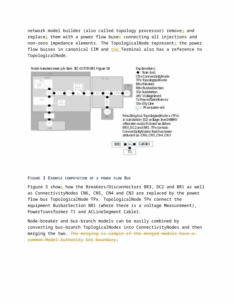
The connectivity information for node-breaker and bus-branch models are shown in the upper right of Figure 2 to the upper right. Each ConductingEquipment has a number of Terminals corresponding to the number physical connection points at the ConductingEquipment. In a node-breaker model, the connections are described by ConnectivityNodes and the Terminals refer to the ConnectivityNodes where they are connected. As closed Breakers or Disconnectors have zero impedance a network model builder (also called topology processor) removes and replaces them with a power flow buses connecting all injections and non-zero impedance elements. The TopologicalNode represents the power flow busses in canonical CIM and the Terminal also has a reference to TopologicalNode.
2 The EndDevice and Terminal inheritance trees have been reduced to improve clarity, but all attributes have been retained
FIGURE 3 EXAMPLE COMPUTATION OF A POWER FLOW BUS
Figure 3 shows how the Breakers/Disconnectors BR3, DC2 and BR1 as well as ConnectivityNodes CN6, CN5, CN4 and CN3 are replaced by the power flow bus TopologicalNode TPx. TopologicalNode TPx connect the equipment BusbarSection BB1 (where there is a voltage Measurement), PowerTransformer T1 and ACLineSegment Cable1.
Node-breaker and bus-branch models can be easily combined by converting bus-branch ToplogicalNodes into ConnectivityNodes and then merging the two. The merging is simple if the merged models have a common Model Authority Set boundary.
FIGURE 4 SUBSET FOR BUS-BRANCH PROFILE
In Figure 43 we can see a subset of this canonical model in a small Bus-Branch profile. Four of the classes from the original canonical model have been used with a subset of attributes from each. The

inheritance has been collapsed and the mRID and name attribute from IdentifiedObject have been retained in the four classes. EnergyConsumer retains only the p and q attributes from the canonical model class Figure 7 IEC profiling practices and standards and all other attributes have been omitted from the profile. The ACLineSegment class retains only the basic attributes required for simple power flow with the zero-sequence attributes from the canonical model discarded for this profile.
At the Terminal level we retain the link to TopologicalNode as this is the CIM class for representing a computed bus in a bus-branch representation of a model. The ConnectivityNode association is removed as this ius used for node-switch models and so is not required for our bus-branch profile. All association cardinalities have been tightened so they are no longer optional. For some associations the minimum and maximum cardinalities are the same, so the EnergyConsumer must have one Terminal association while the ACLineSegment must now have two. Other classes have a restricted minimum and unrestricted maximum, so the TopologicalNode must have at least 1 Terminal. The direction of the association is also defined at the profile such that so an implementation knows which side of the association should be serialised.
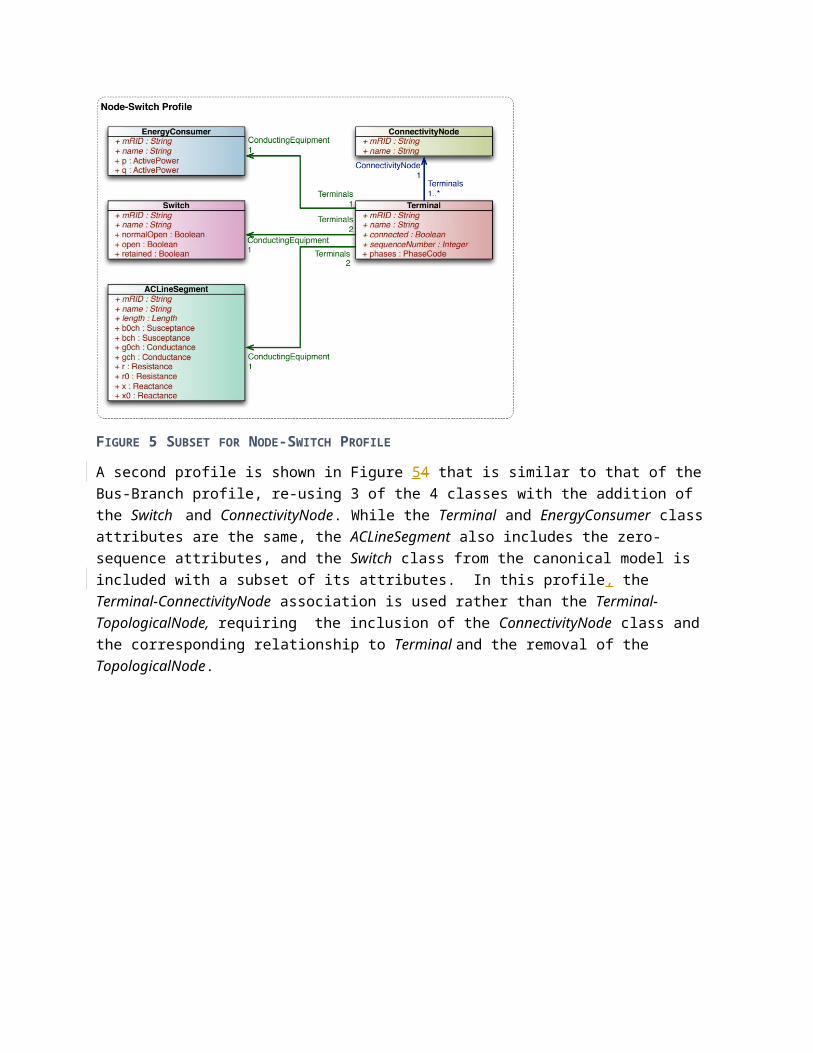
FIGURE 5 SUBSET FOR NODE-SWITCH PROFILE
A second profile is shown in Figure 54 that is similar to that of the Bus-Branch profile, re-using 3 of the 4 classes with the addition of the Switch and ConnectivityNode. While the Terminal and EnergyConsumer class attributes are the same, the ACLineSegment also includes the zero-sequence attributes, and the Switch class from the canonical model is included with a subset of its attributes. In this profile, the Terminal-ConnectivityNode association is used rather than the Terminal-TopologicalNode, requiring the inclusion of the ConnectivityNode class and the corresponding relationship to Terminal and the removal of the TopologicalNode.

FIGURE 6 END DEVICE PROFILE EXAMPLE
Moving outside of the functional model exchange, a simple End Device Profile example is shown in Figure 65. This uses the EndDevice and UsagePoint classes with a small subset of their attributes. The EnergyConsumer class is re-used with some additional attributes added from the canonical model. The general UsagePoint-Equipments relationship has been restricted to only apply to EnergyConsumer (a subclass of Equipment) and, as with the other profiles, the cardinalities have all been restricted and the direction defined.
How IEC uses CIM profilingThe IEC has standardized certain profiles using selected technologies and different options within the flexibility of the profiling process. These techniques are available for any organization using CIM standards and are often employed where specific business processes need exchange implementations that have not been standardized and may include local CIM canonical model extensions as discussed in the CIM modelling guide.

FIGURE 7 IEC PROFILING PRACTICES AND STANDARDS
TODO: If document numbers listed a section that shortly describe each document is required.
A box section for those that want the details how to find CIM documents.
Figure 7 shows the relevant IEC and W3C standards involved in profiling. Note that Pprofiles can be based on any part of the canonical model from any working group and, in the case of project implementations requiring it, local CIM extensions.
Of note is the introduction of a contextual profile (IEC 62325-450) from which further profiles are derived. This contextual profile is useful for restricting the canonical model in a common manner for a set of profiles as is required for example in the European market exchanges. The profiling techniques
are the same at both levels but only the final IEC 62325-45x series of profiles produce payload schema. For the European market messages, the IEC 62325-450 performs more complex restrictions and enables the individual IEC 62325-45x profiles to be simple profile selections and XSD serialization specifications.
Profiles for network analysis models and other closely related data are described in the IEC 61970-4xx profiles and are typically serialized using RDF technology as described in IEC 61970-501 and IEC 61970-552. Profiles for Metering, Assets, Work Management, and similar areas covered by IEC TC57 WG14 typically use XSD based messages and are described in IEC 61968-x standards. By design, the CIM profiling practice allows the same information to be exchanged in multiple technologies, though in practice this does not typically occur. It is common for profiles to make references to CIM data exchanged in different technologies, so the best technology choice can be made for each business exchange.
Payload serialization levelPrevious sections have addressed the upper half of Figure 7 , namely canonical CIM and profile derivation from it by means of restrictions. This section addresses the rest, i.e., syntactic aspects of profiles and considerations to take into account when selecting a syntax.
At present, standard CIM profiles get translated into one of two distinct flavours, both based on W3C XML syntax, as graphically illustrated in Figure Error: Reference source not found(A) , for RDF Schema or RDFS (a) and Figure 7(B) for XML Schema or XSD (b).
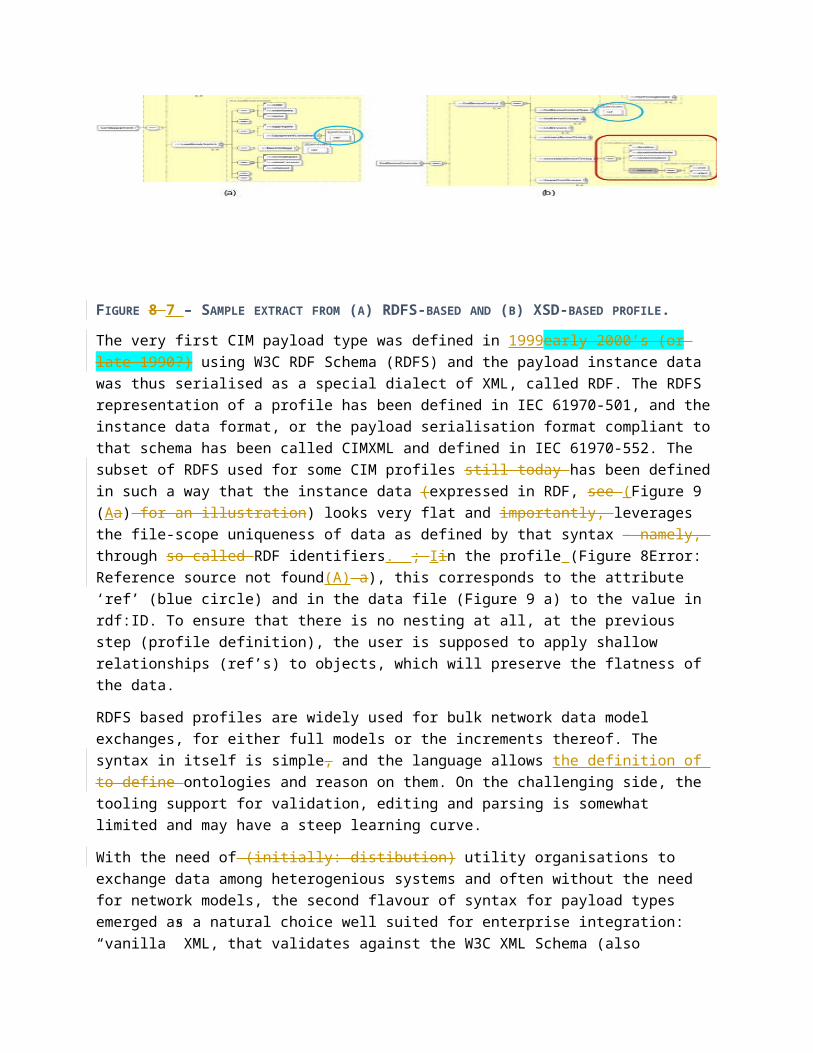
FIGURE 8 7 – SAMPLE EXTRACT FROM (A) RDFS-BASED AND (B) XSD-BASED PROFILE.
The very first CIM payload type was defined in 1999early 2000’s (or late 1990?) using W3C RDF Schema (RDFS) and the payload instance data was thus serialised as a special dialect of XML, called RDF. The RDFS representation of a profile has been defined in IEC 61970-501, and the instance data format, or the payload serialisation format compliant to that schema has been called CIMXML and defined in IEC 61970-552. The subset of RDFS used for some CIM profiles still today has been defined in such a way that the instance data (expressed in RDF, see (Figure (Aa) for an illustration) looks very flat and importantly, leverages the file-scope uniqueness of data as defined by that syntax – namely, through so called RDF identifiers. ; Iin the profile (Figure Error: Reference source not found(A) a), this corresponds to the attribute ‘ref’ (blue circle) and in the data file (Figure a) to the value in rdf:ID. To ensure that there is no nesting at all, at the previous step (profile definition), the user is supposed to apply shallow relationships (ref’s) to objects, which will preserve the flatness of the data.

RDFS based profiles are widely used for bulk network data model exchanges, for either full models or the increments thereof. The syntax in itself is simple, and the language allows the definition of to define ontologies and reason on them. On the challenging side, the tooling support for validation, editing and parsing is somewhat limited and may have a steep learning curve.
With the need of (initially: distibution) utility organisations to exchange data among heterogenious systems and often without the need for network models, the second flavour of syntax for payload types emerged as a natural choice well suited for enterprise integration: “vanilla” XML, that validates against the W3C XML Schema (also referred to as XSD). The translation of CIM profiles into the XSD syntax is defined in IEC 62361-100 and is widely used for standard as well as for custom profiles. This syntax is the mainstream integration technology with a miriad of tools supporting its development. It is , well understood by both application developers and integrators, and is an integral part of web-enabled technologies. The profiles defined with the XSD syntax in mind have no limitation in structure and are indeed often reflecting the “navigation path” through relationships from the canonical CIM model. ; aA graphical example is given in Figure (Bb), with the red rectangle. It is possible to use the “shallow” references as in RDFS based profiles (blue circle);, however, there is no XSD native counterpart to RDF identifiers. - all the more that Ppayloads may not use CIM mRID for identification but since distribution normally requires multiple names for a specific device, but rather thea battery of name-related classes, that have been added with base CIM15 to support object registries. XSD syntax also allows multiple profiles for a single type (e.g., a street address with only street name, street number and postal code; and a street address with all the available descriptors); defined locally or globally. Finally, the work is in progress to support modularity of payload types by enabling the inclusion of a “profile snippet” into multiple profiles. A sample instance data that may comply to an XSD-based profile is shown in Figure (Bb).
FIGURE 9 8 – SAMPLE (A) RDF AND (B) XML SYNTAX FOR CIM-BASED DATA.
Due to its widespread usage in the industry, the majority of new XSD based profiles of standard CIM are defined using XSD syntax, in particular those that support processes outside network model exchanges. The syntax is equally well suited for configuration (“static” / bulk) and for operation (“dynamic” / on-line) data exchanges, as illustrated with e.g., metering profiles from IEC 61968-9. On the challenging side, there is at present no native mechanism for referencing objects used, and referencing may be exclusively through dedicated naming classes.
Note that in theory, a profile defined for use with RDFS syntax can also be expressed with XSD syntax; the other way round is possible only in a special case (where the profile gets defined as if it were for RDFS syntax, i.e., flat, with exclusive use of references).
Messaging and the 61968-100 WS and XSD structuresTo come up to a running software, the first set of objectives is to specify interfaces:
– what is the content (or payload) of data exchanges among actors?
– how is it modelled (in the canonical information model) and how is it translated into an implementation artefact (i.e., some kind of data schema)?
– by which transport it gets exchanged?
while satisfying the requirements, including those related to interoperability. Once we have answered these questions and started specifying concrete data exchange payloads, all actors concerned with any given payload can progress in parallel and independently of each other by implementing and testing their local applications as long as everybody programs to the agreed interfaces.
To allow for this level of flexibility, it is best to adopt for interface specification those technologies that are independent of hardware platform, operating system or programming language. This is the approach also recommended and followed by utility enterprise integration standards such as IEC 61968. In the section “Anatomy of an interface”, we will dissect a message derived from one such sample interface.
Anatomy of an interfaceWe will analyze a message compliant with an interface that has properties discussed above. Left side of Figure 10 shows the general approach to defining communication interfaces by using encapsulation or nesting. Those familiar with the OSI reference model for communication protocols will recognize the idea: The object of exchange (payload) is nested deepest and wrapped into some kind of envelope. That envelope then becomes the object of exchange (payload) one level up and is again wrapped into another kind of envelope. We have denoted three levels in our example:
– L1, the first level, that we will call domain interface level,
– L2, the second level, that we will call message interface level, and,
– L3, the third level, that we will refer to as transport interface level.
In theory, one could go further up and wrap content of L3 into some fourth level, L4, but for our purposes, these three levels are sufficient. The fact that we can clearly separate them means that we can independently develop and test “real” software at each level, while “mocking” the functionality of the other levels. This is an important aspect of any project execution or implementation effort.
Margaret Goodrich <[email protected]>, 07/21/15,
I will generate a smooth transition into this section on the next pass (which I will do this week).
Chavdar Ivanov, 07/13/15,
Please have a look what others articles have on this and make sure this is an addition and goes deeper I am not super familiar with this. I just raise a warning….
Tatjana Kostic, 07/14/15,
Margaret, if you have time, you could cut this intro and make a smooth “passage” from the previous section into the actual exchange of 61968-100.
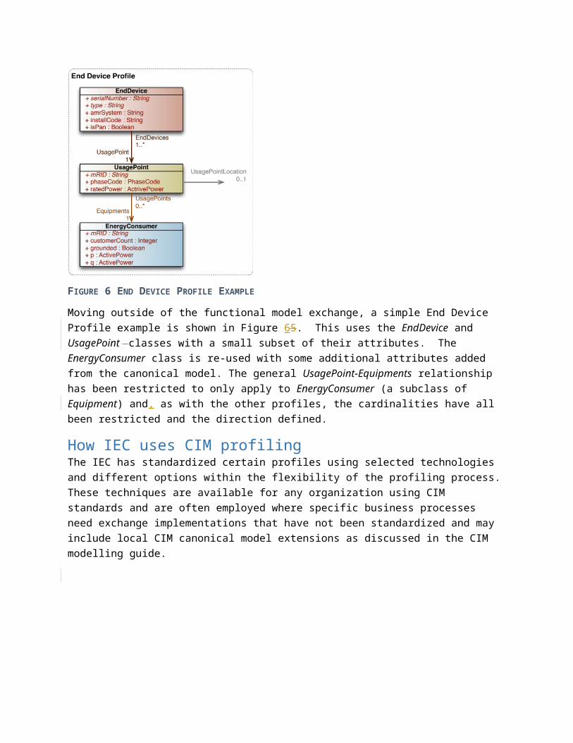
FIGURE 10 – SAMPLE SOAP MESSAGE
Let us now look at the right hand side of Figure xyz-SOAP. This shows a set of very concrete technology choices.
– The domain interface level L1 reflects the payload whose type is called EndDeviceControls and it has been derived from the canonical distribution CIM (defined in IEC 61968-9 and IEC 61968-11, respectively), and that is compliant with the W3C XML Schema format. That specific domain payload allows one, for instance, to send control actions to end devices (such as smart meters) by providing the identity of the end device and the program level for demand response.
– The message interface level L2 reflects the message envelope expressed also in W3C XML Schema format as defined in IEC 61968-100. This is the level where we need to provide extra information that is required by the software that handles message exchanges on a bus and that does not need to “unpack” the payload, but just to route it to the correct receiving applications. Typical information that must be specified are the verb and the noun – telling what needs to be done (verb) with the content of the payload (noun).
– Finally, the transport interface level L3 reflects the standard SOAP message (often meant when one says Web Service), with the SOAP header and the whole of level L2 encapsulated in the SOAP message body.
There may be cases where a single actor needs to exchange some of the messages within a single organization and in a simplified way, without need for platform independence and overhead of e.g. Web Service (and its SOAP implementation). To support this kind of exchange, we could simply skip the transport interface level L3 and pass around the message envelope of level L2 with its containing

payload in level L1 by using e.g. a JMS broker (in a standard way, as in IEC 61968-100) or some other means for message exchange.
The example above has used the payload (L1) in W3C XML format. Given the structure of the envelope (L2), it allows embedding domain payloads in literally any format, including W3C RDF format.
Alternately, for certain data exchange scenarios, simple file exchange may be sufficient in which case the domain payload (L1) would simply be the file to exchange; in this case, some non-standard pre-configuration needs to take place ( e.g. to state the URI of the file on a file system).
InteroperabilityOverviewThe CIM standard was already from its early beginning in 1994 intended to enable interoperability. Originally it was interoperability between applications that has been widened to interoperability between systems. Another widening was from applications for network analysis to work processes within a utility and energy markets as mentioned above. The network analysis has also grown from power flow type of applications to short circuit analysis, dynamics analysis etc. Yet another widening is support for network display layout, geographical locations, assets information, asset health etc.
This widening is still ongoing and extensions are still added. In EU the consequence of the common energy market, increased renewable production and reduction of CO2 emissions resulted in accelerated use of CIM. When ENTSO-E started to use the CIM in its Common Grid Model Exchange Standard (CGMES), needs to further extend the CIM were discovered.
The central architectural idea behind CIM is to describe data semantics such that exchanged data objects can be traced back to the canonical CIM semantics. CIM supports this by is its capability to describe relations between objects, e.g.
Equipment in the functional model (PowerSystemResurce CIM class) relate to physical equipment in the asset model (Asset CIM class). This makes it possible to answer a question like; what is the serial number and actual short circuit current (asset model) of the breaker I am currently using in position Q1 (functional model) in my substation?
Registered resources in the market model relate to generating units in the functional model. This is useful when a production schedule from the market is validated with Congestion Forecast (e.g. in intra-day CF / day-ahead CF) or used in a Security Constrained Unit Commitment (SCUC).
These are just a few examples of many relations between the different parts of the CIM. Relations like this enable cross navigation between data exchanged according to different profiles. Two use cases building on the above examples are
A Supervisory Control and Data Acquisition (SCADA) system typically records how many times a breaker operates. Knowing which breaker in the asset registry is used in the circuit monitored by SCADA can then be used to tell the asset registry how many times the breaker has been operated. This is needed to determine breaker wear.
A market system typically deals with net production from registered units at plant level. Knowing what functional generating units corresponds to a registered unit makes it possible to
Margaret Goodrich <[email protected]>, 07/21/15,
I will edit this on the next round of edits – later this week.
map registered unit net production schedules on functional unit gross production also considering outages and de-ratings. This mapping is needed for Congestion Forecast (CF) and Security Constrained Unit Commitment (SCUC).
Relations between objects require a concise global identification mechanism such that objects are uniquely referenced and not mixed with each other. Human generated names have the drawback that different objects are likely to have the same name, e.g. the substation name “Airport” may exist in many places. Additionally names may need to change over time, but unique identification must be persistent. Hierarchical naming is a usual way to get more precision as with postal addresses, internet addresses etc. But naming schemes like this require authority support and administration for its maintenance. In CIM, the Master Resource ID (mRID) identification scheme is recommended to be used for object identification, for more details see below.
When extending CIM it is important to have use cases such as those mentioned above in mind such that the relations are added to support navigation across profiles. The relations like this need to be present in the CIM canonical model to facilitate cross navigation between profiles. Hence a good modelling practice is to make sure that data shared by different profiles are described in the canonical CIM. The description shall also be precise with clear semantics to avoid that the same data item is used to mean different things in different profiles. Unclear description of a CIM class, attribute or relation has resulted in investigations to figure out the semantics over the past years. So spending time in creating good descriptions make it easier for future users to use the model correctly and avoid duplicate use for different things. Another benefit by being specific is that data that may look the same actually are different when reading the description for the data.
As mentioned above CIM has grown considerably since its creation. This has resulted in a reputation that CIM is continuously changing which is actually true with respect to all extensions. The early parts however have been stable, in particular in recent years. When a new model is added to the CIM it hasn’t typically been implemented yet. As implementations appear issues are normally discovered and corrections are needed. Hence newer parts of the CIM are initially less stable but as interoperability tests aiming at vetting of CIM standards are conducted and usage increases, the model stabilizes. As the usage of CIM has increased the standardization work has also become much more careful in making extensions such that the impact on existing implementations is minimized.
Data structuring / schema / semantic modelThe CIM canonical model (see The canonical model) includes a very large number of classes and each class has associations describing relationships with other classes. Most classes also have attributes describing characteristics of the class. Any given work flow or data exchange will use only a fraction of the classes, associations and attributes defined in the CIM. Profiles (see CIM profiles for data exchanges) are defined to specify the specific subset of classes, associations and attributes from the CIM that are used for a particular data exchange.
Because the information included in a profile is based on the CIM canonical model the meaning of the information is clearly understood. For instance, any profile that includes the class and attribute defining the resistance of an AC transmission line (attribute “r” of the “ACLineSegment” class) will have the same understanding of the data being exchanged.
Tatjana Kostic, 21/07/15,
data item? class?
Tatjana Kostic, 21/07/15,
See next section: this paragraph sounds like repetition of one part of the next section (which reads smoothly). Can we merge anything new here into the next section?My feeling again: Interoperability “points” (unique ids, etc.) should come after discussion on profiles, serialisation etc.
The CIM UML model uses a type system that also helps to ensure a clear understanding of the attributes. CIM data types are defined for common electrical quantities such as “ActivePower,” “AngleRadians,” “Resistance,” and “Susceptance.” For instance, attribute “r” of the “ACLineSegment” class uses the CIM data type “Resistance”.
In most cases a data exchange will need to reference data objects previously exchanged. For instance the results of a power flow will reference the individual pieces of equipment from a network model that was previously exchanged. When changes are made to a network model an incremental update can be exchanged that will reference the objects that have been added, modified or deleted.
Data objects that may need to be referenced have to be kept persistent by the receiver of the data and they must have unique, persistent identification. In CIM the class IdentifiedObject has been defined specifically as a superclass for any class that needs to be persistent after it is initially exchanged. The master resource identifier attribute, “mRID,” of IdentifiedObject is included in the CIM to provide a common method for persistent, unique identification. When used in a data exchange the “mRID” is required to be unique within the context of the exchange. Global uniqueness is achieved by using a Universally Unique Identifiers (UUIDs), which is strongly recommended, but not required.
In an ideal data exchange UUIDs would be used as the mRIDs to uniquely identify all objects, but this cannot always be achieved when working with existing applications that already have other established methods of unique identification. In this case CIM naming attributes and classes such as the “name” attribute on “IdentifiedObject” or the alternate name classes “Name,” “NameType,” and “NameTypeAuthority” can be leveraged.
Data partitioning Network model data documents representing large interconnected power networks may become large. This is dealt with by partitioning documents in two ways
Documents with different types of data described by different CIM Profiles. Documents with parts of instance data from different Model Authorities.
As described in the “Data structuring” section CIM data is divided into profiles that enable exchange of non-overlapping data facilitating a modular division of data in sets that can be exchanged when needed. As a network part of a power system is typically managed by an authority, e.g. an organization being responsible for or operating the network part, the CIM concept of a Model Authority and Model Authority Set has been created. In an interconnected power system with multiple responsible organizations the Model Authority Sets are defined by the boundaries between them. Both the network parts and the boundaries between them are Model Authority Sets and their data can be exchanged as separate sets.
Data composition by receiving systemsThe main objective of CIM is to support utility business processes and these normally require the assembly or composition of data from a number of sources. These sources may use different exchange
Tatjana Kostic, 07/14/15,
Important, but must be shortened and simplified; I think that (some text from) interoperability section would be better placed around here.
Tatjana Kostic, 07/21/15,
(in terms of type; in terms of instance)?
Tatjana Kostic, 07/21/15,
horizontal partitioning / sharding?
Tatjana Kostic, 07/21/15,
vertical partitioning?
Tatjana Kostic, 07/21/15,
what about just exchanging data that is not necessarily network model (persistent) data? I think we need a statement about it. Margaret?

technologies, different (but related) schema or structure, and different content which is often referencing other content.
CIM based integration enables systems to more readily compose and utilize data originating from multiple sources and potentially with different (but related) structure and content.
FIGURE 11 DATA PARTITIONING BY INSTANCE AND BY SCHEMA
As shown in Figure 4 there are two main ways CIM data is partitioned.
1) Model Authority Sets partition by instance – e.g. by transmission operators
Chavdar Ivanov, 07/13/15,
Perhaps it is better to spell out EQ and TP and next to it write 61070-452 and 61970-456

2) Profiles partition by schema – e.g. by network model
Data may be exchanged in different technologies. For example, a network model exchanged using RDF XML technology and network outage data exchanged using XSD based XML. We expect the semantics and object identities to be valid across technologies such that the outages could relate to the network model. Additionally we may exchange both full models and incremental changes to be applied to full model descriptions.
By considering all exchanged data to be conforming to a common semantic model, we can describe how data from different technologies, different sources, and different profiles will compose within a receiving system. We focus upon the receiver here, but of course data providers must adhere to standards in order for the receiver to benefit.
Chavdar Ivanov, 07/13/15,
I think the reference to TSO1 and TSOn is maybe not so much appropriate. What if the TSO also gives the load forecast.Maybe you can replace TSO1 and TSOn by network equipment and topology or something like that

FIGURE 12 BUSINESS PROCESS COMPOSING DATA
To some, the composition of CIM data is obvious, but for clarity and in preparation for describing more complex situations, we go through how CIM objects compose.
We describe a generalized “receiver model context” (RMC) in which CIM data is to be composed within the business process. This context defines each business object to be uniquely defined by an MRID. Thus references to business objects within that context can be implemented using MRID’s. IEC does not standardize internals of business process implementations, but the interface standards are designed such that a business process can implement a consistent composed model of the various input standards.
Kurt Hunter, 06/04/15,
Using actual CIM classes here could make this clearer for power systems engineers.
Chavdar Ivanov, 07/13/15,
The box “CIM Information Model ” could be “Common Information Model (CIM)” What do you mean by CIM – app 1? Application? Perhaps it is better to be something like “Application - sender” and then you take the other as “Application - receiver”. I do not see a need to refer to CIM in these boxes.

FIGURE 13 OBJECT LEVEL COMPOSITION
shows an example of how a receiver with CIM data can compose new data.
class BMRID=2
payload 1
payload 2
RMC
class AMRID=1
class BMRID=2
Proxy class A
MRID=1
class AMRID=1
unordered

<< Still some work in this section. Break double figures apart. Add short conclusion. Intend to be only slightly longer, or about the same size when delete this paragraph. Remove “Resource” from schema/instance partitioning diagram. Maybe combine the object example to show both references and attributes composition in same diagram.>>
Conclusions
Definitions
(1) Canonical CIM:
This is an abstract model of domain or data exchange (our CIM UML).
(2) Profile:
This is a restriction of canonical CIM, a small subset of it as required for a specific interface for external data exchanges (although people may take the same approach for internal system interfaces). We use a profiling tool to reduce canonical CIM to the desired content, and the tool produces for us a schema that will govern the format of the instance data to be exchanged.
(3) Payload:
This is an instance of Profile according to a given syntax. We use XML (complying with RDFS or XSD); in future we may want to use something else (e.g. JSON format); others may already be using something else based on CIM, or CIM extensions or not related to CIM at all. (note TK: this is L1 from Figure xyz-SOAP)
(4) Message:
This is an instance of message envelope, e.g. Message.xsd (61968-100), that includes among others one or more Payloads (3). It also contains the full context of data exchange (verb, noun, etc.) to let the receiver know what to do with the received payload. (note TK: this is L2 from Figure xyz-SOAP)
(5) Dataset:
TBD
(6) Models:
Model – Data that describes an existing entity or thing.
Electrical network model – A model or data describing an electrical network.
Base model – An electrical network model used as part of a case.
As built model – an electrical network model that corresponds to a constructed network
Tatjana Kostic, 07/14/15,
How about putting these together with the figure that shows 4 levels (Figure 1)?
Chavdar Ivanov, 07/13/15,
This might be helpful to have Is it possible to turn it in a chart (a big one) or combine it in other charts where you refer to the thing?I think visual + text would be better than just the text.Another option is to create a table.
Margaret Goodrich <[email protected]>, 07/21/15,
I will add this section later this week in the next round of edits – it will only be about 2-3 sentences.
Tatjana Kostic, 07/14/15,
What’s the main message? from the intro: we provide a vast set of standards based on common semantic, that can be tailored to custom needs as well.

Case – complete set of inputs to a network analysis study case.
Full model – A complete description of an electrical network model.
Difference model or Incremental model: TODO add description
Further Readings– up to 6 items (note TK: this leaves place for 4 more; should we add reference to actual series: 61968, 61970 and 62325? If so, one more left.)
CIM modelling guide
CIM Primer
A. deVos, October 2000, "Simplified RDF Syntax for Power System Model Exchange", http://www.langdale.com.au/DAF/PSModelExchange.Pdf.
A. deVos, S. Widergren, J. Zhu, "XML for CIM Model Exchange", 22nd IEEE Int. Conf. On Power Industry Computer Applications (PICA), Conference Proceedings, Sydney, Australia, May 2001, pp31- 37.
Authors– one line per author
Tatjana Kostic is with ABB Corporate Research, Baden-Daettwil, Switzerland.
Margaret Goodrich is with Project Consultants, LLC, Shell Knob, MO, USA