CHAINCASE AND BRAKE - Vintage Sno VIII CHAINCASE AND BRAKE Contents of this Section Brake System...
46
SECTION VIII CHAINCASE AND BRAKE Contents of this Section Brake System Identification See Reverse Side Chaincase Data (1972 through 1987) . . .... 1 - 2d Chain and Sprocket Specifications for Models Equipped with Cross-Over Jackshafts . . . . . . . . . . . . . . 2a Bleeding Procedures For Polaris Brake Systems 3 Hydraulic Brake Adjustment and Master Cylinder Overhaul 4 Master Cylinder Exploded View . . . . . 5 Type I Slave Cylinder Removal and Repair . 6 Type I Slave Cylinder Exploded View. . . 7 Type II Brake Caliper Removal and Repair . 8 Type II Brake Caliper Repair and Assembly. 9 Type III Brake Caliper Removal and Repair. 10 -/ i 1 Type III Brake Caliper Assembly. . . . . 12 Type IV Brake Overhaul and Pad Replacement . 12a - 12b 12c , ,1 Type V Brake Exploded View. . . . . . Chaincase Exploded View - Type I Systems 13 I Drive Chain Adjustment and Lubrication - Type I Systems 14 Chaincase Exploded View - Types II and III Systems. . . 15 Drive Chain Adjustment and Lubrication - Types II and III Systems. '16 Drive Chain Sprocket Alignment. . . . . . . 17 Front Drive System Overhaul - Standard Models 18 - 22 Front Drive System Overhaul - Models with Transmissions 22a - 22e Series 300 Transmission Overhaul 22f - 22j Jackshaft Speed VS Miles Per Hour. 23 5/86
Transcript of CHAINCASE AND BRAKE - Vintage Sno VIII CHAINCASE AND BRAKE Contents of this Section Brake System...

SECTION VIII
CHAINCASE AND BRAKE
Contents of this Section
Brake System Identification See Reverse Side
Chaincase Data (1972 through 1987) . . .... 1 - 2d
Chain and Sprocket Specifications for Models Equipped with Cross-Over Jackshafts . . . . . . . . . . . . . . 2a
Bleeding Procedures For Polaris Brake Systems 3
Hydraulic Brake Adjustment and Master Cylinder Overhaul 4
Master Cylinder Exploded View . . . . . 5
Type I Slave Cylinder Removal and Repair . 6
Type I Slave Cylinder Exploded View. . . 7
Type II Brake Caliper Removal and Repair . 8
Type II Brake Caliper Repair and Assembly. 9
Type III Brake Caliper Removal and Repair. 10 -/i 1
Type III Brake Caliper Assembly. . . . . 12
Type IV Brake Overhaul and Pad Replacement . 12a - 12b
12c ,
,1 Type V Brake Exploded View. . . . . .
Chaincase Exploded View - Type I Systems 13 I
Drive Chain Adjustment and Lubrication - Type I Systems 14
Chaincase Exploded View - Types II and III Systems. . . 15
Drive Chain Adjustment and Lubrication - Types II and III Systems. '16
Drive Chain Sprocket Alignment. . . . . . . 17
Front Drive System Overhaul - Standard Models 18 - 22
Front Drive System Overhaul - Models with Transmissions 22a - 22e
Series 300 Transmission Overhaul 22f - 22j
Jackshaft Speed VS Miles Per Hour. 23
5/86
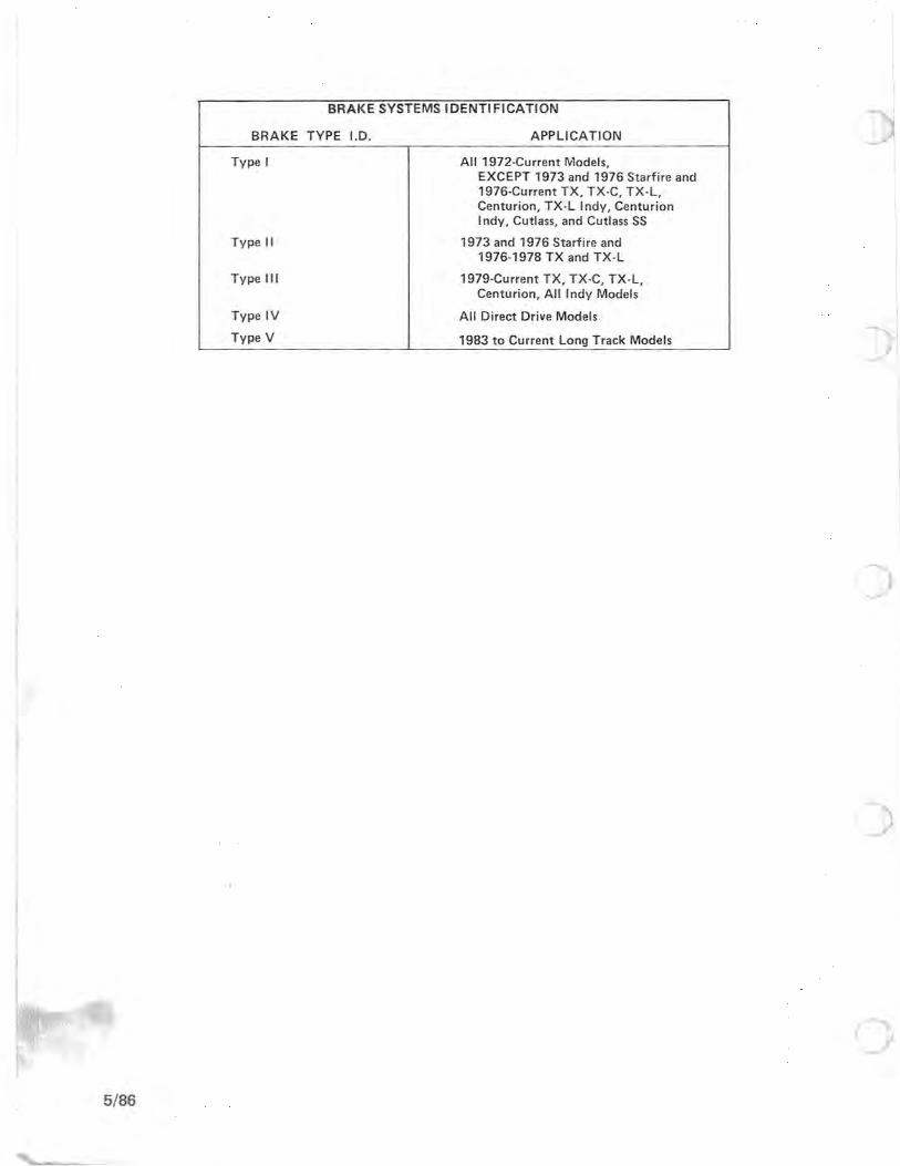
BRAKE SYSTEMS IDENTIFICATION
BRAKE TYPE 1.0. APPLICATION
Type I All 1972-Current Models, EXCEPT 1973 and 1976 Starfire and 1976-Current TX, TX-C, TX-L, Centurion, TX-L Indy, Centurion Indy, Cutlass, and Cutlass SS
Type II 1973 and 1976 Starfire and 1976-1978 TX and TX-L
Type III 1979-Current TX, TX-C, TX-L, Centurion, All Indy Models
Type IV All Direct Drive Models
Type V 1983 to Current Long Track Models
(
5/86
c
1 9 7 2
1 9 7 4
Machine
Model
Colt
Colt
Colt
Colt SS
Colt SS
Charger
Charger
Charger
Charger SS
Charger SS
Mustang
Mustang
TX
TX
Machine Model
Colt
Colt
Colt
Colt SS
Colt SS
Colt SS
Electra
Electra
Custom II
Custom II
Custom II
TX
TX
TX
TX
TC
TC
Engine
Model
EC17P
EC25P
EC29P
EC29PF
EC34PF
EC29P
EC40P
EC54P
EC40PF
EC54PF
EC40P
EC54P
EC34PS
EC51PS
Engine Model
EC17PM
EC25PS
EC29PF
EC25PC
EC29PF
EC34PC
EC34PQ
EC44PQ
EC25PS
EC40PM
EC54PM
EC25PT
EC34PS
EC44PT
EC51PT
EC17PM
EC25PS
Sprocket Ratio
12/35
13/35
13/35
13/35
13/35
13/39
15/41
17/41
15/41
17/4 1
13/39
15/39
13/39
17/39
Sprocket Ratio
12/35
13/35
13/35
13/35
13/35
15/35
15/39
15/39
13/39
15/39
17/39
13/39
15/39
17/39
19/39
14/39
14/39
Drive O1ain
Type Pitch
35-2 84
35-2 84
35-2 84
35-2 84
35-2 84
35-2 90
35-2 90
35-2 92
35-2 90
35-2 92
35-2 90
35-2 90
35-2 90
35-2 92
Drive O1ain
Type Pitch
35-2 84
35-2 84
35-2 84
35-2 84
35-2 84
35-2 86
35-2 90
35-2 90
35-2 90
35-2 90
35-2 92
35-2 90
35-2 90
35-2 92
35-2 92
35-2 84
35-2 84
1 9 7 3
1 9 7 5
VIII - 1
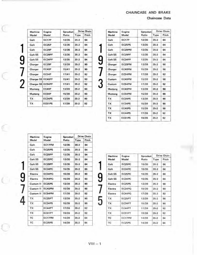
CHAINCASE AND BRAKE
Chaincase Data
Machine Engine Sprocket Drive Chain
Model Model Ratio Type Pitch
Colt EC17P 12/35 35-2 84
Colt EC25PS 13/35 35-2 84
Colt EC29PM 13/35 35-2 84
Colt ss EC29PF 13/35 35-2 84
Colt SS EC34PF 13/35 35-2 84
O1arger EC29PM 13/39 35-2 90
O1arger EC40PM 15/39 35-2 90
O1arger EC54PM 17/39 35-2 92
Custom EC40PM 15/39 35-2 90
Custom EC54PM 17/39 35-2 92
Mustang EC40PM 13/39 35-2 90
Mustang EC54PM 15/39 35-2 90
TX EC29PS 13/39 35-2 90
TX EC34PS 15/39 35-2 90
TX EC40PS 15/39 35-2 90
TX EC44PS 17/39 35-2 92
TX EC51PS 19/39 35-2 92
Machine Engine Sprocket Drive Chain
Model Model Ratio Type Pitch
Colt EC25PC 15/35 35-2 86
Colt EC34PC 15/35 35-2 86
Colt SS EC25PC 15/35 35-2 86
Colt SS EC34PC 15/35 35-2 86
Electra EC25PS 13/39 35-2 90
Electra EC34PQ 15/39 35-2 90
Electra EC44PQ 17/39 35-2 92
TX EC25PT 13/39 35-2 90
TX EC34PT 15/39 35-2 90
TX EC44PT 17/39 35-2 92
TX EC51PT 19/39 35-2 92
TC EC17PM 14/39 35-2 84
TC EC25PS 14/39 35-2 84

CHAINCASE AND BRAKE
Chaincase Data
1 9 7 6
1 9 7 8
Machine Model
Co l t
Co lt
Colt
Col t
Colt SS
Colt SS
Elect ra
Elect ra
Electra
TX
T X
TX
Starfi re
Starfire
Machine
Model
Colt
Colt
SIS 340
Cobra
Cobra
TX
TX
TX
TX·L
Engine Sprocket
Model Ratio
EC17PM 12/35
EC25PS 13/35
EC25PC 15/35
EC34PC 15/35
EC25PC 15/35
EC34PC 15/35
EC25PS 13/39
EC34PQ 15/39
EC44PQ 17/39
EC25PT ·06 14/39
EC34PT·05 17/39
EC44PT·05 19/39
EC25PT·05 14/39
EC34 PT·06 15/39
Engine Sprocket
Model Ratio
EC25PS 13/35
EC25PC 15/35
EC34PM-03/04NI17/35
EC34PM·04 15/35
EC44PM·01 17/33
EC25PT·07 15/39
EC34PT·05 17/39
EC44PT·05 19/39
EC34PL·02 19/39
Drive Chain
Type Pitch
35-2 84
35·2 84
35·2 86
35·2 86
35·2 86
35-2 86
35-2 90
35·2 90
35-2 92
Si lent 64
Silent 66
Si lent 66
Silent 64
Silent 64
1 9 7 7
Drive Chain
Type
35·2
Silent
Silent
Silent
Silent
Silent
Silent
Silent
Silent
Pitch
84
86
86
88
88
64
66
66
66
1 9 7 9
VIII - 2
Machine Engine Sprocket Dr ive Cha in
Model Model Ratio Type Pitch
Colt EC25PS 13/35 3 5-2 84
Colt EC25PC 15/3 5 35 -2 86
Colt SS EC25PM -01 15/35 35-2 86
Colt SS EC34PM ·03 17/35 35-2 86
Electra EC25PS 13/39 35·2 90
Electra EC34PQ 15/39 35-2 90
Electra EC44PQ 17/39 35-2 92
TX EC25PT -07 15/39 Sil ent 64
TX EC34PT·05 17/39 Silent 66
TX EC44 PT·05 19 /39 Si lent 66
TX EC44PT ·06 19 /39 Silent 66
TX-L EC34PL·01 19 /39 Silent 66
Machine Engine Sprocket Drive Chain
Model Model Ratio Type Pitch
Gemini EC25PS 13/35 35·2 84
Gemini EC25PM·01 15/35 Silent 86
Apollo EC34PM-03 18/35 Silent 88
Cobra EC34PM·04 15/35 Silent 88
Cobra EC44PM·01 17/33 Silent 88
TX EC25PT -07 15/39 Silent 64
TX EC34PT·05 17/39 Silent 66
TX EC44PT·05 19/39 Silent 66
TX·L EC34PL·02 19/39 Silent 66
Centurion EC51 PL·01 19/35 Silent 64

(
c
)
)
1 9 8 o
CHAINCASE AND BRAKE
Chaincase: Data-
Machine Engine Sprocket Drive Chain Model Model Ratio Type Pitch Links Wide
Gemini EC25PS 13/35 35-2 84 --
Gemini EC25PM-01 15/35 Silent 86 8
Apollo EC34PM-03 18/35 Silent 88 8
Galaxy EC34PM-04 15/35 Silent 88 8
Galaxy EC44PM-01/02 17/33 Silent 88 8
TX/TX-C EC34PT-07 17/39 Silent 66 11
TX EC44PT-05 19/39 Silent 66 11
TX-L/TX-L Indy EC34PL-02/05 19/39 Silent 66 11
Centurion EC51PL-02 19/35 Silent 64 11
CHAIN AND SPROCKET SPECIFICATIONS FOR MODELS EQUIPPED WITH CROSS-OVER JACKSHAFTS
Sprocket Combination Gear Ratio Chain Pitch
21/35 1.67 0 64 19/35 1.84 I- 64 ~ 21/39 1.86 a: 66 18/35 1.94 a: 64 w 21/41 1.95 :I: 68 C!? 19/39 2.05 :I: 66 17/35 2.06 62 19/40 2.11 68 19/41 216 66 18/39 217 66 16/35 2.19 62 18/41 2.28 68 17/39 2.29 66 15/35 233 62 17/40 2.35 66 17/41 2.41 66 16/39 2.44 64 16/40 250 66 14/35 2.50 62 16/41 2.56 66 15/39 2.60 0 64 15/40 2.67
I-~ 64
15/41 2.73 a: 66
14/39 2.79 a: w 64
14/40 2.86 $: 64 0 14/41 2.93 ...J 64
VIII - 2a

CHAINCASE AND BRAKE
Chaincase Data
1 9 8 1
1 9 8 2
3/81
Machine Model
Gemini
Galaxy
Cutlass
Cutlass SS
TX-C
TX-L/TX-L Indy
Centurion Indy
Machine Model
Cutlass SS
TX-C
TX-L/TX-L Indy
Centurion Indy
Engine Model
EC25PS
EC44PM-02
EC34PM-03
EC44-2PM-
3100/3300
EC44-2PM-
1100
EC34PL-05
EC51PL- 02
Engine Model
EC44-2PM-
3100
EC44-2PM-
1100
I EC34PL-05
EC51PL-02
Sprocket Drive Chain Ratio Type Pitch Links Wide
13/35 35-2 84 - -
17/33 Silent 88 8
-- -- -- - -
-- - - - - - -
19/35 Silent 64 11
19/39 Silent 66 11
19/35 Silent 64 11
Sprocket Dr ive Chain
Ratio Type Pitch Links Wide
-- I -- -- --
19/35 Silent 64 11
19/39 Silent 66 11
19i35 Silent 64 11
(J VIII - 2b

1 c 9
c
8 3
~1
9 c 8
4
o
Machine Model
Gemini
Star
Sport
SS
Indy Trail
I ndy Cross Cou ntry
Indy 600
Long Track
Machine
Model
Star
SS
Indy Trail
Indy 600
Star L T
Long Track
Engine Chaincase
Model Gearing
EC25PS 13/35
EC25PS Direct Drive
EC44-2PM-5100 Direct Drive
EC44-2PM-3100 Direct Drive
EC44-2PM-2100 19/35
EC34PL-05 19/39
EC60PL-01 21/35
EC44-2PM-5000 19/39
Engine Chaincase
Model Gearing
EC25PS-05 Direct Drive
EC44-2PM-3100 Direct Drive
EC44-2PM-2100 19/35
EC60PL-02 19/35
EC25PS-05 15/39
EC44-2PM-5000 19/39
VIII - 2c
CHAINCASE AND BRAKE
Chaincase Data
Drive Chain
Type Pitch Li nks Wide
35-2 84 --
- - -- --
-- -- --
-- -- --
Silent 64 11
Silent 66 11
Silent 64 11
Silent 66 11
Drive Chain
Type Pitch Links Wide
-- -- - -
-- -- --
Silent 64 11
Silent 64 11
Silent 64 11
Silent 66 11
5/83

-
CHAINCASE AND BRAKE
Chaincase Data
1 9 8 5
1 ;
9 8 6
1 II
9 8 7
Machine Model
Star
SS
Indy Trail
Indy 400
Indy 600
Long Track
Machine Model
Star
Sprint (ES)
SS
Indy Trail
Indy 400
Indy 600 (LEI
Long Track
Machine Model
Star
Star Trak
Sprint (ES)
Indy Sport
Indy Trail (All)
Indy 400
Indy 600
Long Track(RLR)
Engine
Model
EC25PS-06
EC44-2PM-3100
E C44-2PM-21 00
EC40PL-02
EC60PL-02
EC44-2PM-5000
Engine Model
EC25PS-06
EC34-2PM
EC44-2PM-3100
EC50PM-01
EC40PL-02
EC60PL-02
EC44-2PM-5100
Engine Model
EC25PS-06
EC25PS-06
EC34-2PM-01/02
EC34-2PM-03
EC50PM-01
EC40PL-02
EC60PL-02
EC44-2PM-5100
Long Track RLR Ratios - High Range 2.05/1
Chai:1case
Gearing Type
Direct Drive - -
Direct Drive --
19/35 Silent
19/35 Silent
19/35 Silent
19/39 Silent
Chaincase Gearing Type
Direct Drive - -
Direct Drive - -
Direct Drive - -
21/35 Silent
19/35 Silent
21/35 Silent
19/39 Silent
Chaincase
Gearing Type
Direct Drive - -
15/39 Sil ent
Direct Drive - -
17/35 Si lent
21 /35 Si lent
19/35 Si lent
21/35 Silent
19/39 Silent
Low Range 3.56/1
5/86 VIII - 2d
Drive Chain
Pitch Links Wide )
- - --
- - - -
64 11
64 11
64 11
66 11
Drive Chain Pitch Links Wide
-- - -
- - - -
-- --
64 11
64 11
64 11
66 11
Drive Chain Pitch Links Wide
- - --
64 11
- - - -
62 11
64 11
64 11
64 11
66 11
Reverse 2.85/1

)
CHAINCASE AND BRAKE
Bleeding Procedures for Polaris Brake Systems
The Polaris hydraulic brake mechanism consists of a handlebar mounted master cylinder, a hydraulically operated plunger assembly (slave cylinder) integrally mounted in the chaincase rear cover, an adjustable brake pad and a self aligning brake disc mounted in the chaincase.
The master cylinder contains a fluid reservoir and a cylindrical pressure chamber in which force applied to the brake lever is transmitted to the fluid which actuates the plunger assembly in the chaincase rear cover. A coil spring, located in the master cylinder, holds the piston assembly against the actuating force of the brake lever. A piston assembly consists of a piston, "U" seal and a rubber "0" ring.
SERVICE 1. Air in the hydraulic system will cause a spring
or spongy action of the brake lever. A bleed ing operation is necessary to remove air in the system. Fill the master cylinder with standard automotive type brake fluid or Polaris silicone brake fluid (PN 2870251).
2. Slip a ru bber t ube over the ball of the bleeder valve and d irect f luid away f rom painted areas. NOTE: Care must be taken to wipe any accidentally spilled f luid from painted surfaces.
3. Slowly squeeze brake lever a full stroke and hold. Unscrew bleeder valve 3/4 turn to release air. Close bleeder valve, then release brake lever. Repeat the above procedure until fluid flows from bleeder valve in a solid stream that is free of air. Check master cylinder periodically to make sure that it contains fluid. Fluid should be 1/8" from top of reservoir area. Fill with brake fluid and install new gasket.
VIII - 3

CHAINCASE AND BRAKE
Hydraulic Brake Adjustment and Master Cylinder Overhaul
BRAKE ADJUSTMENT - BRAKE SYSTEM TYPEI
A If there is excessive brake pad clearance, turn set screw (A) clockwise until pads are tight against the disc, then back off the screw 1/4 turn counterclockwise. Re·tighten the lock nut (B).
NOTE : When the head of the adjustment screw contacts the locknut, new brake pads should be installed.
BRAKE SYSTEMS TYPE II AND III
These systems are self adjusting and do not require adjustments.
MASTER CYLINDER OVERHAUL
1. Remove the master cylinder assembly from the machine taking care not to spill brake fluid on painted surfaces. On models equipped with molded velox master cylinder, remove existing rivet, as shown. This will have to be replaced with a new pin (PN 7661615) and retaining ring (PN 7710401) upon reassembly.
2. Remove the piston and springs from the master cylinder discarding the rubber "U" cup, "0" ring, and cover gasket. I nspect the cylinder bore for scores, scratches or corrosion. All cylinder parts must be very clean and not be
allowed to come in contact with any lub· ricating oil. When reassembling, dip all internal parts in brake fluid, also wet the cylinder bore. Install new "U" cup and "0" ring to the piston. Next install the springs and piston into the master cylinder bore exercising care to insure the seal is not damaged. Install lever with a new pin and retainer. Assemble the master cylinder to the handlebar, adjusting and bleeding air from system as covered in this section. Use a new cover gasket to prevent leakage.
." ~
" ~ OOUU·uU,,,uW1,,,, ~: .iUXn.H V
o
~oo . .. 7J:.-:-
VIII - 4
(

--------
c
o
CHAINCASE AND BRAKE
Cylolnder Exploded View Master
CAST ALUMINUM MASTER CYLINDER
MOLDED VELOX MASTER CYLINDER
VIII - 5

CHAINCASE AND BRAKE
Type I Slave Cylinder Removal and Repair
1. Remove the air box, driven clutch, brake line, brake light switch wires, and five cap screws from chaincase rear cover.
2. Apply heat to bearing area and slide rear cover and slave cylinder assembly from the shaft. NOTE: On· some models it may be necessary to loosen chaincase to enable the rear cover to clear the chaincase mounting gussets.
3. Remove piston retaining snap ring. Remove washer, spring, and plunger from rear cover and discard. Clean rear cover thoroughly with brake flu id or denatured alcohol. CAUTION: Do not use methanol·base anti· freeze or any other cleaning fluid that may contain even a trace of mineral oil. Inspect bore for scores, scratches, or corrosion. Slight corrosion may be cleaned with fine crocus cloth and alcohol.
4. Dip all internal parts in clean brake fluid. Use automotive brake fluid or Polaris silicone brake fluid (PN 2870251). Wet cylinder bore and install "0" rings on plunger and insert into rear cover.
A Care must be taken not to damage "0" rings. Torque rear cover bolts evenly as numbered. Bleed system as outlined on page VIII - 3 .
. .,
)
00
VIII- 6

c
(
c VIII -7
CHAINCASE AND BRAKE
Type I Slave Cylinder Exploded View

CHAINCASE AND BRAKE
Type I I Brake Caliper Removal and Repair
1. Remove the hydrau lie line, exercising care to prevent fluid spillage on painted surfaces.
2. Remove the two bolts (A) which hold the cal iper halves together and the four bracket mounting screws (8).
3. Remove the friction pads, noting the difference between the stationary side and piston side pads. NOTE: When replacing friction pads only, it is important to make room for new pads. The piston must be pushed back into the slave cylinder bore. Use Loctite on the two friction pad attach ing screws.
4. Piston removal is facilitated by the use of A compressed air at the in let fitting. Extreme
caution must be exercised to prevent fluid f rom getting in eyes. Cover the assembly with a shop rag as shown.
5. In pect the cy linder and p iston for scoring. idence of s ere scoring in the caliper bore
ill mean re I ing the housing and piston to btal a pr r piston seal.
VIII -- 8

c
()
6. Dip the piston assembly and the "0" ring seal in brake fluid; assemble the seal to the piston. Press the piston into the caliper bore keeping it square to avoid scoring the bore. Push it firmly all the way in.
7. Reassembly is basically the reverse of disassembly procedures. Be sure that all components are clean and serviceable before reassembling the unit.
Observe the following:
A. Apply Loctite (PN 2870326) compound on the two (2) caliper ca rrier bolts and four (4) bracket attaching cap screws.
Torque Values
Caliper carrier bolts - 25 - 30 ft./lbs. Caliper attaching bracket cap screws -8 ft./lbs.
B. Purge the system of all trapped air by
bleeding as outlined on page VIII - 3.
C. Inspect for system leaks.
D. Check caliper unit mount for free floating action.
CHAINCASE AND BRAKE
Type II Brake Caliper Repair and Assembly
TYPE II SLAVE CYLINDER EXPLODED VIEW r
VIlI-9 ., -

CHAINCASE AND BRAKE
Type II I Brake Caliper Removal and Repair
1. Remove the hydraulic line, exercising care to
prevent fluid spillage on painted surfaces.
2. Remove spring clips (9), figure 1, which hold the pad retaining pins (10).
3. Remove the two bridge bolts (A) holding the caliper halves together and the four bracket mounting screws (B).
IMPORTANT: Note brake light switch adapter (C) which is used on all Type III brake systems, except Centurion. The Centurion has a special brake light switch which does not require the use of an adapter. All brake light switches, except Centurion, have l/S" NP thread. The Centurion has a 3/S x 24 NF thread and a flared end. Therefore, care must be taken when replacing these switches so as not to interchange them and cause possible damage to caliper assemblies.
REPLACING FRICTION PADS
The pad is attached to a pad holder and is replaced. as a set.
1. To make room for new pads, the piston must be pushed back into the caliper bore. Loosen the bleeder screw and work the piston back into the bore.
2. Take out pad retaining pins and remove worn friction pads.
3. Install new pad holders. Brake pads should be replaced only as a set.
4. With unit reassembled, apply brakes lightly several times to seat the new pads against the disc.
15
Figure 1
VIII - 10
1 - Piston Casting 2 - Carrier Casting 3 - Piston Seal 4 - Piston 5 - Pad Assembly (2) 6 - Seat Insert (2) 7 - Brass Adapter S - Stop Light Switch 9 - Spring Clip (2)
10 - Pad Retainer Pin (2) 11 - Bleeder Screw 12 - Bridge Bolt (2) 13 - Spacer Bushing (4) 14 - Nut (2) 15 - Bracket 16 - Male Adapter 17 Ferrule Fitting 18 - Female Connector

c
c
c
c
CHAINCASE AND BRAKE
Type III Brake Caliper Removal and Repair
DISASSEMBL V
Refer to the exploded view while performing steps below. Numbers in parenthesis correspond to callouts in figure 1.
NOTE: Only take apart as far as needed to make repairs.
1. Disconnect hydraulic line.
2. Disassemble on a clean bench.
3. Open bleed screw (11) and drain brake fluid from caliper assembly. A CAUTION: PROTECT EVES FROM FLU ID.
4. Remove the spring clips (9) that hold the pad retainer pins (10) and remove the pins.
5. Remove the two bridge bolts (121.
6. Separate casti ngs (1) an d (21.
7. Place cal iper with piston down and remove piston (4) from piston casting (1) by applying compressed air to the hydraulic inlet port. A CAUT ION: Use just enough air to do the job. Use extra care not to damage the piston or piston bore.
8. Using a sma ll wood or plastic stick, work out pist on sea l (3) from its groove in the piston bore. Discard old seal. A CAUTION: To avoid scratching piston or burring edge of seal groove, do not use a metal tool such as a screwdriver.
CLEANING AND INSPECTING
Check all parts for wear or damage and replace any found defective.
1. Clean all parts with denatured alcohol and wipe dry with a clean, lint-free cloth. Using an air hose, blowout the drilled passages and bores.
• 2. Inspect casting cylinder bore for scoring, pitting, or corrosion. A corroded or deeply scored casting should be
replaced; light scores and stains may be removed.
3. Polish any discolored or stained area with crocus cloth only. Use finger pressure and rotate the crocus cloth in the cylinder bore. Do not slide the cloth in and out of the bore under pressure. Do not use any other kind of abrasive or abrasive cloth. Black stains on the bore walls are caused by the piston seals and do no harm.
4. Check piston to see if it is pitted, scored, or worn. If so, discard and replace the piston. Do not attempt to polish or sand piston.
5. Clean piston with denatured alcohol and wipe dry with a clean, lint-free cloth. Using an air hose, blow dry.
6. Check in let and bleeder hole threads for damage.
7. Inspect seat insert (6) for damage and replace if necessary.
VIII - H

• . . .
CHAINCASE AND BRAKE
Type III Brake Caliper Assembly
~ 18
ASSEMB LY
Figure 1
1 - Piston Casti ng 2 - Carrier Casting 3 - Piston Seal 4 - Piston 5 - Pad Assembly (2) 6 - Seat Insert (2) 7 - Brass Adapter 8 - Stop Light Switch 9 - Spring Clip (2)
10 - Pad Retainer Pin (2) 11 - Bleeder Screw 12 - Bridge Bolt (2) 13 - Spacer Bushing (4) 14 - Nut (2) 15 - Bracket 16 - Male Adapter 17 - Ferrule Fitting 18 - Female Connector
Reassembly is basically the reverse of disassembly. Be sure that all parts are clean and serviceable before reassembling the unit.
1. Dip a new piston seal (3) in clean brake fluid and place in groove in the cylinder bore. Seal should be posi· tioned at one point in groove and then gently worked around the groove by hand until properly seated. Never use an old seal.
2. Install piston (4) into cylinder bore as follows. Coat piston thoroughly with brake fluid and carefully work piston down the bore until bottomed. A CAUTION: Apply force uniformly to avoid cocking piston in bore.
3. Examine pads for wear or damage. If pads are worn to less than half original thickness, install new pad holder assemblies. If pads are okay, they may be reused. Be sure pads are installed in their original positions. If pads are replaced, replace in sets.
4. Replace pad retainer pins (10) and spring clips (9). Observe the following:
A. Be sure bolts and nuts are clean and dry. Apply Loctite (PN 2870326) compound on the two caliper carrier bolts and four bracket attaching cap screws.
B.
C.
D.
Torque Values: Caliper carrier bolts - 30 ft./lbs .
Caliper attach ing bracket cap screws - 8 ft.!lbs .
Purge the system of all trapped air by bleeding as outlined on page VIII - 3.
Inspect for system leaks.
Check caliper unit mount for free floating action.
VIII - 12

)
)
1.
19
19
3 'I
2 ! i
7 4 5 6
1 Adjuster Bolt and Stop 2 Jam Nut 3 Jam Nut Locking Tab
4 Actuating Lever 5 Helix Shaft
6 Brake Pad Retainer 7 Caliper Casting 8 Movable Brake Pad 9 Brake Disc
10 Carriage Bolt 11 Stationary Pad Assembly
Open the ad juster bolt jam nut locking tab (A).
Loosen the jam nut and remove the adjuster bolt (B).
2. Remove the actuating lever (C) and return spring.
3. Remove the two brake caliper attaching nuts (0).
4 . Remove the cable bracket and caliper assembly . Check cable condition at both ends - frayed or binding brake cables must be replaced.
8
9
12 13 14 15 16 17 18 19 20 21 22
VIII - 12a
CHAINCASE AND BRAKE
Type IV Brake Overhaul and Pad Replacement
14
Front Drive Shaft Drive Shaft Bearing Flangette Brake Disc Key Front Drive Sprocket Nut 5/16 Caliper Attaching Bolt (2) Return Spring Cable Sleeve Jam Nut (2) Caliper Attach ing Nut (2 ) Brake Cable Bracket Brake Cable
.., ':',

CHAINCASE AND BRAKE
Type IV Brake Overhaul and Pad Replacement
5. Slide the brake disc off the front drive shaft. NOTE: Check brake disc condition and mounting. Replace disc as needed.
6. Clean the drive shaft in brake disc area. Lightly lubricate with anti-seize.
7. Remove the carriage bolt (A). Remove the pad assembly and replace with a new assembly.
8. Install brake disc. A CAUTION: The disc must float or slide freely
on the front drive shaft.
9. Replace the movable pad assembly and install the caliper onto the attaching bolts. Install brake cable bracket and torque the attaching nuts to 30 ft./lbs.
10. Loosen the cable sleeve jam nuts and adjust the brake cable sleeve to its shortest position.
A CAUTION: The following step is critical for proper positioning of the actuating arm to the caliper helix shaft.
11. With the brake lever bottomed on handlebar and the helix shaft (A) bottomed in caliper, install the actuating arm, jam nut locking tab, jam nut, and adjuster bolt.
12. Insert a .015" feeler gauge between the brake disc and movable brake pad. Release the brake lever. Install the return spring and tighten the cable sleeve jam nuts. Turn the adjuster bolt in finger-tight. Set the adjuster bolt jam nut; bend the locking tab and remove the feeler gauge. Field-test unit for proper braking action.
3/81 VIII - 12b
::' .
(
(

\--~2-~_
ke Cable Nut (2) 1. Bra leeve Jam
2 . Cable S (2) Bolt 3. Bridge I Bracket Cab e
Brake hing (4) 4 . acer Bus 5.
Sp . Bracket 6. Carner
c Nut (2) ) 7.
ke Pad (2 8 . Bra ting rper Cas 9 . Ca I S ring
10. Return p
Nut . 11. ble ClevIs 12. Ca. olt
ClevIs B It 13. . r Bo 14. AdJuste o
VIII - 12c
BRAKE AND CHAINCASE I ded View
e V Exp 0 Typ
6
15. Adjuster Bolt Stop
Jam Nut king Tab 16. Nut Loc 17. Jam
Bushing er 18. . g Lev ActuatlO 19.
. Shaft 20. HeliX . Plate d BacklOg 21.
Pa C sting ) 22. Caliper a Screw (4
k t Cap 23. Brac e (4) Washer 24. Lock . (2)
25. Snap Rmg
26. Bra ke Disc
27. Key
28. Jac k Shaft
it,.
·5/82

U!
I

-
VIII - 13
CHAINCASE AND BRAKE Chaincase Exploded View- Type I Systems
J~ II .~ •

CHAINCASE AND BRAKE
Drive Chain Adjustment and Lubrication- Type I Systems
DRIVE CHAIN TENSION
To obtain correct chain tension, remove the chaincase cover. With a slight reverse tension on the chain, turn driven clutch as indicated (A). There should be approximately 3/8" deflection on the chain at point (81. Chain adjustment is achieved with the adjusting bolt (CI. Install the cover and add chaincase oil to lower plug level; install cover plugs (upper vented).
VIII - 14
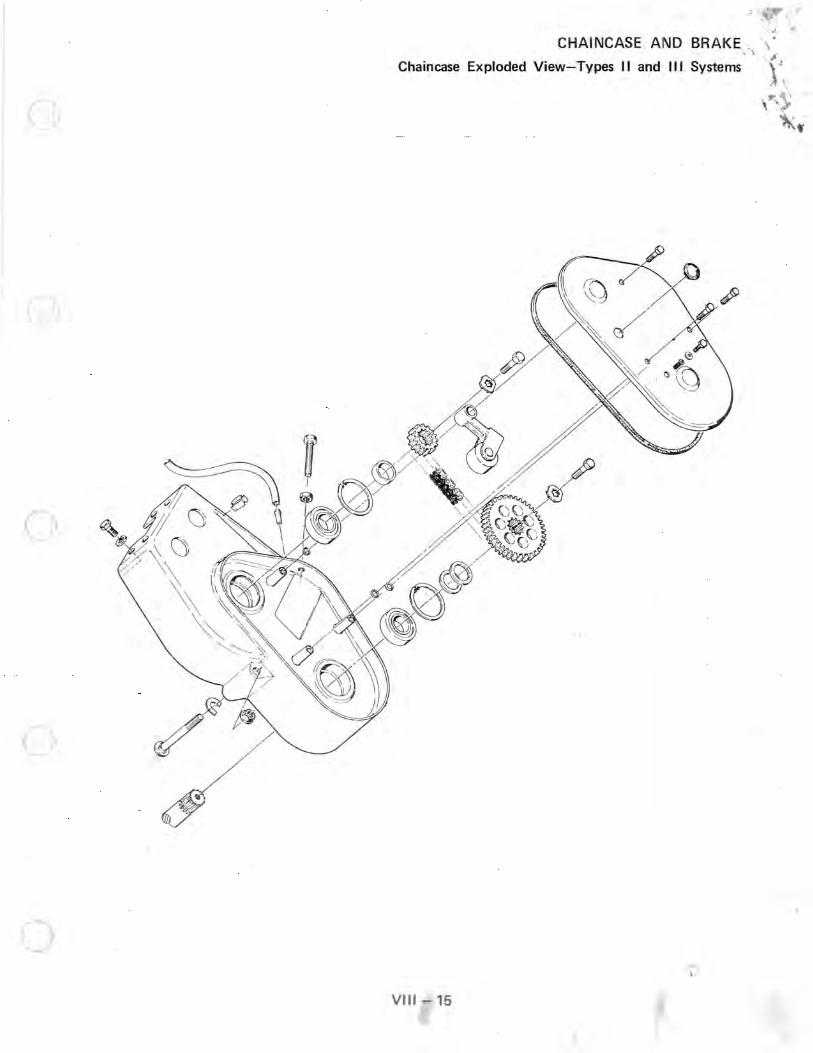
Chain CHAINCA ";, .' case Exploded V . SE AND BRAKE '·.1 '"' lew-T . ' . . ypes II and III S ' \.',. . ystems \~ ',
.~ \ . I
c
o
c
o VtII - 15

CHAINCASE AND BRAKE
Drive Chain Adjustment and Lubrication-Types II and III Systems
@
c
DRIVE CHAIN TENSION
To obtain correct chain tension, remove the chaincase cover with a slight reverse tension on the chain by turning driven clutch as indicated (A). There should be approximately 1/4" - 3/8" free play deflection on the chain at point (8). Chain adjustment is achieved by loosening the adjusting bolt locknut and turning adjusting bolt (C) until correct chain deflection is obtained. Lock the adjusting bolt locknut while holding a wrench on the adjusting bolt at the same time to prevent it from turning and changing your desired chain tension. Install the chaincase cover and add Polari s chaincase lubricant (PN 2870337) through the cover upper plug hole to the lower check plug level.
VIII - 16
(

f'[
c~
CHAINCASE AND BRAKE
Drive Chain Sprocket Alignment
Maximum sprocket and chain life are directly related to proper sprocket alignment Before installing the drive chain, place a straight edge against the upper and lower installed sprockets. The edge should contact equally on both sprockets. If misalignment is evident, the addition or subtraction of washers (PN 7556509) is necessary behind the bottom sprocket to correct the problem.
VIII - 17 ".:-..s;. ."

CHAINCASE AND BRAKE
Front Drive System Overhaul
DISASSEMBl Y
1. Remove the hood.
2. Remove the air silencer and the exhaust system {exhaust silencer and expansion chamber can be removed as a unit!.
3. Remove the drive belt and driven clutch. {Note the position of clutch offset washers'!
4. Prior to tipping the machine on its left side, the A fuel tank must be drained or siphoned to pre· vent any fuel spillage.
5. loosen the jackshaft bearing locking collar set screw. Rotate the bearing locking collar and slide it away from the bearing.
6. Remove the three flangette attaching nuts and washers located on the left side of the front drive shaft.
7. Remove the four suspension mounting bolts. Tip the machine on its left side and remove the suspension. loosen the front drive shaft locking collar set screw; rotate the bearing lock collar and slide it away from the bearing. NOTE: Prior to tipping the machine on its side, we advise you place a piece of cardboard or carpet under the nosepan to reduce scratch· ing of the nosepan or bumper.
8. Remove the four caliper attaching bracket capscrews (A) and the three chaincase cover bolts (B).
3/81 VIII - 18
1
o
u

c
c
o
9. Loosen the chain adjuster bolt jam nut and remove the adjuster. Remove the chain, top and bottom gears. (Note position of gear spacer and sh ims for proper gear alignment upon reassembly.) Remove the three chaincase attaching nuts and carriage bolts (A) .
10. Install a 5/16" x 3/4" standard threaded bolt into the jackshaft and drive the shaft out through the upper case bearing. Remove the front drive shaft and track.
11. Remove the stop light switch wires and lift the brake caliper assembly from the brake disc. A CAUTION: Do not squeeze brake lever with caliper removed.
12. Remove the three flangette attaching bolts from the left side of jackshaft. The bottom flangette bolt is accessible from the UNDER· SIDE of tunnel as shown. ·The jackshaft can now be removed.
VIII - 19
CHAINCASE AND BRAKE
Front Drive System Overhaul
I 3/81

CHAINCASE AND BRAKE
Front Drive System Overhaul
13. JACKSHAFT INSPECTION: Inspect the jackshaft bearing in support area as shown. If any wear is noted, the shaft must be replaced. Also remove the brake disc and inspect brake disc key and keyways. If the key or keyways show signs of wear, the brake disc and jackshaft should be replaced. If the brake disc is glazed, it should also be replaced. Lubricate the iackshaft between snap rings with anti-seize and reinstall brake disc.
REASSEMBLY
Be sure all parts are clean and serviceable before proceeding with reassembly. NOTE: It is important that the following reassembly steps be performed in sequence to prevent misalignment and possible component failures.
1. Remove and replace the upper and lower chaincase bearings. Replace the chaincase cover gasket. Use a small amount of silicone sealer at the ends of the cover gasket.
2. I nstall the jackshaft as shown and place the .caliper assembly onto the brake disc.
3. Place the chaincase into position on the bulkhead and onto the jackshaft. (NOTE: Do not bolt chaincase to bulkhead at this time.) Install
the jackshaft alignment tool with bolt and washer as shown. Tighten the alignment tool bolt until the jackshaft is seated into the upper chaincase bearing.
3/81 VIII - 20
o
()

C
c
C>
4. Install and tighten the three chaincase attaching carriage bolts and locking nuts. Apply Loctite to the fou r caliper attaching bracket capscrews and f inger·tighten into ca rrier bracket. With the brake applied , torque capscrews (A ) to 8 ft./lbs. Rei nstall stop light switch wi res.
5. Install a fla ngette into the left bearing support hole. With al ignment tool torqued to 6 ft./lbs., the shaft should be centered as shown. If not, the chaincase will have to be shimmed between the bulkhead and case using shim kit 22001 26 as needed to position the shaft on center.
6. Install the track and front drive shaft assembly. Remove the jackshaft alignment tool and install top and bottom gear shims, chain, and gears. Tighten gear retainer bolts; check gear align· ment and chain tension as outlined in this sec· tion.
7. Install the bearing assembly onto the left side drive shaft and tighten the three carriage bolts.
8. Lightly rotate the bearing locking collars (jack· shaft and drive shaft!. Tighten the allen·head set screws.
Ii
VIII - 21
CHAINCASE AND BRA~E
Front Drive System Overhaul
3/81

CHAINCASE AND BRAKE
Front Drive System Overhaul
9. Add three ounces of Polaris chaincase oil into the chaincase and reinstall chaincase cover. NOTE: One full stroke on the pump = 1 ounce of oil. Polaris h ighly recommends the use of t his oil for extended gear and chain life.
10. Reinstall the suspension. Torque suspension mount ing bolts to 35- 40 ft./lbs.
11 . Rei nstall air silencer, exhaust system, and driven clutch. Check and adjust clutch offset. Refer to page 17 for correct offset specifica· tions and too l.
IMPORTANT STEP TO PREVENT BEARING SIDE LOADING AND CLUTCH MISA LI GNMENT DUR· ING DRIV EN CLUTCH BOLT TI G HTENING.
12. With driven clutch properly positioned, meas· ure the distance between the alignment spacer (A) and the outer edge of the driven clutch hub (8). This distance must be taken up by using washer(s) PN 7555734 (C). Reinstall clutch retaining bolt, washer and drive belt .
13. Reinstall the hood and field·test the unit for proper front drive operation .
5/85 VIII - 22
)
c
CHAINCASE AND BRAKE
Drive System Overhaul For Models With Transmissions
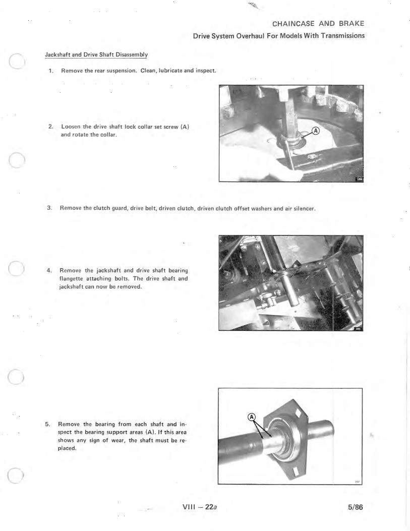
Jackshaft and Drive Shaft Disassembly
1. Remove the rear suspension . Clean, lubri cate and inspect.
2. Loosen the drive shaft lock collar set screw (A) and rotate the collar .
3 . Remove the clutch guard, d rive belt, dr iven clutch, driven clutch offset washers and air silencer.
4. Remove the jackshaft and drive shaft bearing
flangette attaching bolts. The drive shaft and
jackshaft can now be removed .
5 . Remove the bearing from each shaft and inspect the bearing support areas (A). If this area
shows any sign of wear, the shaft must be replaced.
VIII - 22a 5/86
CHAINCASE AND BRAKE
Drive System Overhaul For Models With Transmissions
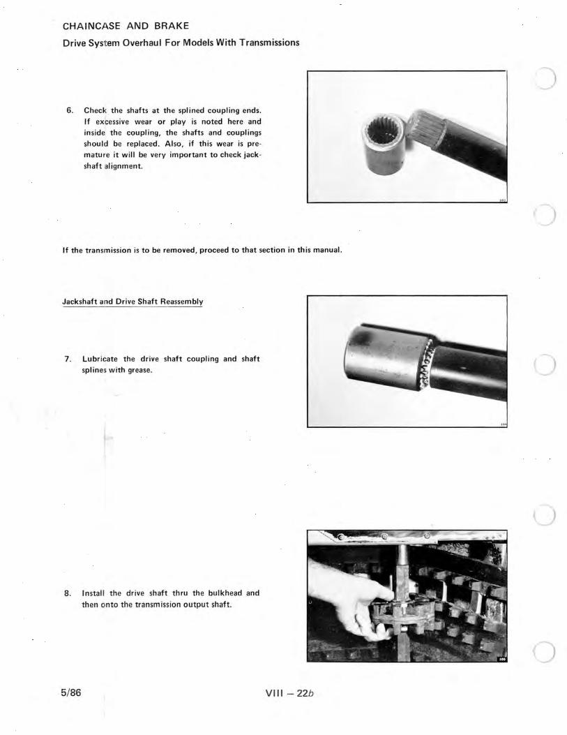
6 . Check. the shafts at the splined coupling ends .
If excessive wear or play is noted here and inside the coupling, the shafts and couplings should be replaced . Also, if this wear is pre
mature it will be very important to check jack
shaft alignment.
If the transmission is to be removed, proceed to that section in this manual.
Jackshaft and Drive Shaft Reassembly
7 . Lubricate the drive shaft coupling and shaft
splines with grease .
8 . Insta ll the drive shaft thru the bulkhead and
then onto the transmission output shaft.
5/86 VIII - 22b

c
c
c·
9. Lubricate the fl angettes and outer race of
bearing.
10. I nstall the bearing lock collar , inner flangette,
new bearing and outer flangette onto the drive shaft.
11. Install the speedometer drive key, angle drive
and attaching bolts, washers, nuts and tighten.
12. Tightly position the bearing lock collar up
against the bearing inner race . Tighten the allen
head set screw while pulling up on the drive shaft in direction shown.
CHAINCASE AND BRAKE
Drive System Overhaul For Models With Transmissions
'.'
VIII - 22c 5/86

CHAINCASE AND BRAKE
Drive System Overhaul For Models With Transmissions
Jackshaft Alignment
\ 13. Lubricate the jackshaft coupling and splines
with grease. I nstall the jackshaft thru the bulk
head and onto the transmission input shaft. (Use mUlti -purpose automotive chassis grease.)
Orbit the shaft in the bulkhead bearing support
opening. There should be an equal distance between the shaft and the bulkhead bearing
support during this orbit.
14. To correct any jackshaft misalignment the transmission will need to be shimed between
the bulkhead and transmission (A). Use Shim
Kit PIN 2200126 to correct any misalignment. This kit includes 3 of each of the following
shims: .020" thickness, .063" thickness, .080" thickness.
15. The above shims ca n be installed between the bulkhead and transmission in three locations.
16. Clean the bearing support area with Primer T
and apply a stud and bearing mount to the
shaft in the bearing area.
5/86 VIII - 22d
J

(
CHAINCASE AND BRAKE
Drive System Overhaul For Models With Transmissions
17. Install a new bearing, the outer flangette and flangette attaching bolts. Install the driven clutch and check driven
clutch offset. Torque driven clutch bolt to 12 ft./lbs.
Reinstall the rear suspension, drive belt, air silencer and clutch guard . Field test for proper operation .
VIII - 22e 5/86

CHAINCASE AND BRAKE
Series 300 Transmission Overhau l
Transmission overhau l should also include dr ive system overhaul. This is covered earlier in drive system overhau l fo r
models wi t h a transmission.
After removing the dr ive shaft and jackshaft proceed as follows:
1. Remove the fou r cal iper carrier attach ing bolts (A ). Remove the two ca li per bridge bolts (8). Remove the brake cali per and brake disc .
2. Remove the shift linkage (A) and the stop light switch wires (8) .
3. Remove the exhaust system . Remove the three nuts that secure the transmission to the front bulkhead and remove the transmission. IMPORTANT: Check position of transmission shims for reference in reassembly. (A) These shims control jackshaft alignment.
4. Remove the transmission drain plug (A) and drain the oil.
5/86 VIII - 22f

c
5. Place the transmission as shown and remove the shift lever and key (A) neutral light switch (B), detent set screw, spring and ball (e).
Loosen the chain tensioner jam nut and remove the chain tensioner bolt.
6. Remove the transmission housing attaching bolts. (A)
7. Lift upwards on the inner housing and tap (with a soft hammer} on the input shaft, output shaft, and the shift shaft.
8. Remove the high range long silent chain (A).
VIII - 22g
CHAINCASE AND BRAKE
Series 300 Transmission Overhaul
5/86
CHAINCASE AND BRAKE
Series 300 Transmission Overhau l
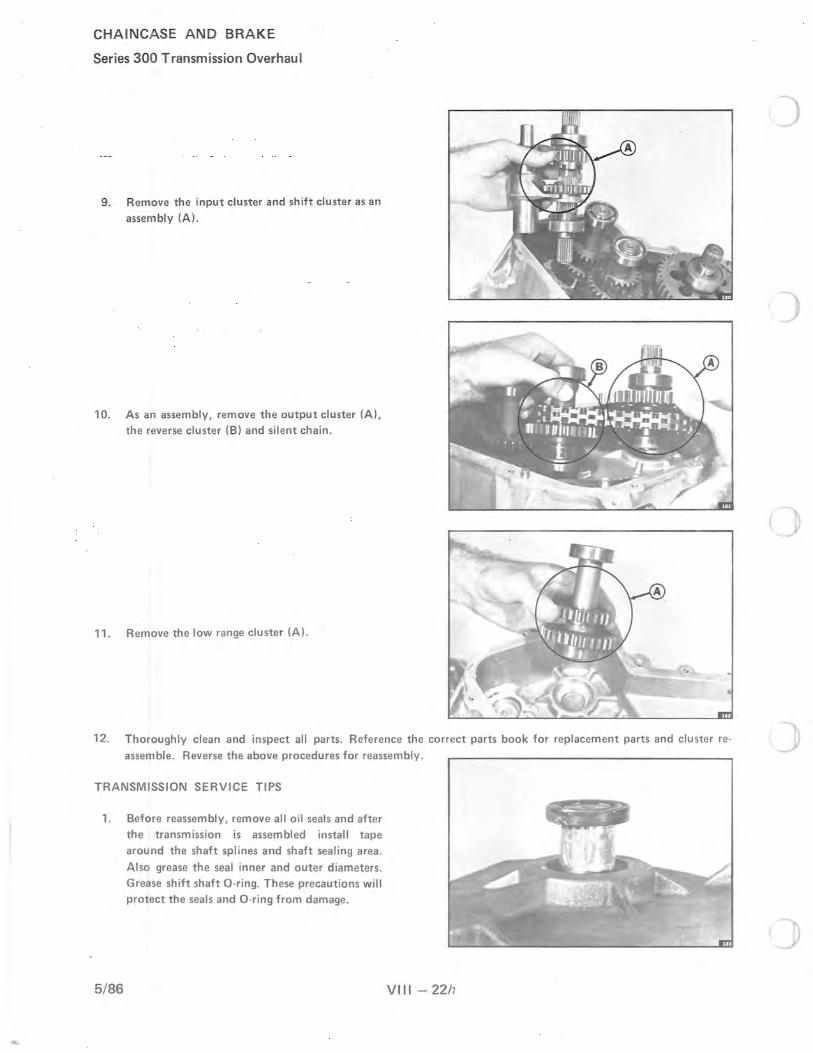
9. Remove the input cluster and sh ift cluste r as an assembly (A).
10. As an assembly, remove the output cluster (A), the reverse cluster (B) and silent chain .
11. Remove the low range cluster (A).
12. Thoroughly clean and inspect all parts. Reference the correct parts book for replacement parts and cluster reassemble. Reverse the above procedures for reassembly.
TRANSMISSION SERVICE TIPS
1. Before reassembly, remove all oil seals and after the transmission is assembled install tape around the shaft splines and shaft sealing area_
Also grease the seal inner and outer diameters. Grease shift shaft O-ring. These precautions will protect the seals and O-ring from damage.
5/86 VIII - 22h
(

c 5. Place the transmission as shown and remove
the shift lever and key (A) neutral light switch (B), detent set screw, spr ing and ball (e).
Loosen the cha in tensioner jam nut and remove the chain tensioner bolt.
6. Remove the transmission housing attach ing bolts. (A)
7. Lift upwards on the inner housing and tap (with a soft hammer) on the input shaft, output shaft, and the shift shaft.
8. Remove the high range long silent chain (A).
VIII - 22g
CHAINCASE AND BRAKE
Series 300 Transmission Overhaul
5/86

CHAINCASE AND BRAKE
Series 300 Transmission Overhaul
9. Remove the input cluster and shift cluster as an assem bly (A).
10. As an assembly, remove t he output cluster (A), the reverse cluster (B) and silent chain.
11 . Remove the low range cluster (A).
12. Thoroughly clean and inspect all parts. Reference the correct parts book for replacement parts and cluster reo
assemble. Reverse the above procedures for reassembly.
TRANSMISSION SERVICE TIPS
1.
5/86
Before reassembly, remove all oil seals and after the transmission is assembled install tape around the shaft splines and shaft sealing area.
Also grease the seal inner and outer diameters. Grease shift shaft O·ring. These precautions will protect the seals and O·ring from damage .
•
VIII - 22h
)

(
2. Be sure the case half mating surfaces are clean and free of any nicks or scratches. Place a small amount of Gasket Elim inator 515, (Polaris PIN 2870587) on one of the case halves.
3. I nstall bearings and seals using service tool PIN 2870676. Bearings, gears, etc. are assembled until they bottom on each other or onto snap rings or shoulders.
4. I nstall the detent ball and spring. Apply a medium strength thread locking compound
to the allen head set screw and install it to a depth of .060" to .120" below the casting surface. During field testing check the detent preload. If the detent is adjusted too tightly, the unit will become hard to shift. If the detent is too loose it will effect the operator's preception of the shift position.
5. Chain tension adjustment is accomplished by loosening the jam nut (A), torqueing the bolt (B) to 20 in./lbs. Then loosen the bolt 1/2 turn and while holding the bolt, tighten the jam nut.
VIII - 22i
CHAINCASE AND BRAKE
Series 300 Transmission Overhaul
SET SCREW
t .06/.12
5/86

CHAINCASE AND BRAKE
Series 300 Transmission Overhaul
6. After the transmission is installed onto the bulkhead, be sure to align the jackshaft as ca lled out on drive system overhaul for models with transmission.
7. With the transmission installed on the unit, fill the t ransm ission to the correct level using only Polaris chaincase oil.
5/86 VIII - 22j
. (;~'Q
(! }h)@~, , \
I I 1i 0
I (. , ' FdiC' 1~\ l' Plug ,"
Mag ne t Ie Ch eck \, / ~. :r ~ ~!I L,~vel -' > t. OraHl Plug
.©Y ,; '
)

<
N W
U'1 -(Xl U'1
\, '-."./
INDY JACKSHAFT SPEED VIS MILES PER HOUR
SPROCKE T COMBINATION/GEAR RATIO/CHAIN PITCH
()
Jackshaft-- 21/35 19/35 21/39 18/35 21 /4 1 19/39 17/35 19/40 19/41 18/39 16/35 18/41 17/39 15/35 17/40 17/41 16/39 16/40 14/35 16/41 15/39 15/40 15/41 14/39 14/40 14/41
RPM 1.67 1.84 1.86 1.94 1.95 2.05 2.06 2.11 2.16 2.17 2. 19 2.28 2.29 2.33 2.35 2.41 2.44 2.50 2.50 2 .56 2.60 2.67 2.73 2.79 2.86 2.93
Pitch 64 64 66 64 68 66 62 68 66 66 62 68 66 62 66 66 64 66 62 66 64 64 66 64 64 64
6500 82.7 74.8 74.2 70.9 70.6 67.1 66.9 65.4 63.8 63.6 63.0 60.5 60.1 59.0 58.6 57.1 56.5 55. 1 55.1 53.8 53.0 51.7 50.4 49.5
6600 83.9 75.9 75 .3 71.9 71.7 68.2 68.0 66.5 64.8 64.6 64.0 61 .4 61 .0 60.0 59.5 58.0 57.4 56.0 56.0 54.6 53.8 52.5 51 .2 50.2
6700 85.2 77.1 76.5 73.0 72 .7 69.2 69.0 67.5 65.8 65.5 64.9 62.3 61 .9 60.9 60.4 58.9 58.3 56.8 56.8 55.4 54.6 53.3 52.0 51 .0
6800 86.5 78.2 77 .6 74.1 73.8 70.2 70.0 68.5 66.8 66.5 65.9 63.3 62.8 61.8 61.3 59.8 59.1 57.7 57 .7 56.2 55.4 54.1 52.7 51.7
6900 87.8 79.4 78.8 75.2 74.9 71.3 71.0 69.5 67.8 67 .5 66.9 64.2 63.8 62.7 62 .2 60.6 60.0 58.5 58.5 57.1 56.3 54.8 53.5 52 .5
7000 89.0 80.5 79.9 76.3 76.0 72.3 72.1 70.5 68.8 68.5 67.8 65.1 64.7 63.6 63.1 61 .5 60.9 59.4 59.4 57.9 57.1 55.6 54.3 53.3
7100 90.3 81.7 81. 0 77 .4 77.1 73.3 73.1 71 .5 69,7 69.5 68.8 66.1 65.6 64.5 64.0 62.4 61 .7 60.2 60.2 58 .7 57.9 56.4 55.1 54.0
7200 91 .6 82.8 82.2 78.5 78.2 74.4 74 .1 72.5 70.7 70.4 69.8 67.0 66.5 65.4 64.9 63.3 62.6 61.0 61 .0 59.6 58 .7 57.2 55 .8 54.8
7300 92.8 84.0 83.3 79.6 79.3 75.4 75 .2 73.5 71 .7 71 .4 70.7 67.9 67.4 66.3 65.8 64.2 63.5 61.9 61.9 60.4 59.5 58.0 56.6 55.5
7400 94.1 85.2 84.5 80.7 80.3 76.4 76.2 74.5 72.7 72.4 71.7 68.9 68.4 67.2 66.7 65.0 64.4 62.7 62.7 61.2 60.3 58.8 57.4 56.3
7500 95.4 86.3 85.6 81.8 81.4 77.5 77.2 75.5 73.7 73.4 72.7 69.8 69.3 68.1 67 .6 65.9 65.2 63.6 63.6 62.0 61.1 59.6 58.2 57 .1
7600 96.7 87.5 86.7 82.8 82.5 78.5 78.2 76.5 74.7 74.4 73.6 70.7 70.2 69.0 68.5 66.8 66.1 64.4 64.4 62.9 62.0 60.4 58.9 57 .8
7700 97.9 88.6 87.9 83.9 83.6 79.5 79.3 77.5 75.6 75.3 74.6 71 .7 71 .1 69.9 69.4 67.7 67 .0 65.3 65 .3 63.7 62 .8 61.2 59 .7 58.6
7800 99.2 89.8 89.0 85.0 84 .7 80.5 80.3 78.5 76.6 76.3 75.6 72.6 72.1 70.9 70.3 68.6 67 .8 66.1 66.1 64.5 63 .6 62.0 60.5 59.4
7900 100.5 90.9 90.2 86.1 85.8 8 1.6 81.3 79.5 77 .6 77 .3 76.6 73.5 73.0 71 .8 71 .2 69.4 68 .7 67.0 67 .0 65.3 64 .4 62.8 61 .3 60.1
8000 101 .7 92.1 91 .3 87.2 86.9 82.6 82.4 80.5 78.6 78.3 77 .5 74.4 73.9 72.7 72.1 70.3 69.6 67.8 67 .8 66.2 65 .2 63.6 62.0 60 .9
8100 103.0 93.2 92.5 88.3 87.9 83.6 83.4 81 .6 79.6 79.2 78.5 75.4 74.8 73.6 73.0 71 .2 70.4 68.7 68.7 67.0 66.0 64.4 62.8 61.6
8200 104.3 94.4 93.6 89.4 89.0 84.7 84.4 82.6 '80.5 80.2 79.5 76.3 75.8 74.5 73.9 72.1 71 .3 69.5 69.5 67.8 66.9 65.2 63.6 62.4
8300 105.6 95.5 94.7 90.5 90.1 85.7 85.5 83.6 81 .5 81 .2 80.4 77.2 76.7 75.4 74.8 72.9 72.2 70.4 70.4 68.7 67.7 66.0 64.4 63.2
8400 106.8 96.7 95.9 91.6 91.2 86.7 86.5 84.6 82.5 82.2 81.4 78.2 77 .6 76.3 75.7 73.8 73.0 71.2 71.2 69.5 68.5 66.8 65.1 63.9
8500 108.1 97 .8 97.0 92.7 92.3 87.8 87.5 85.6 83.5 83.2 82.4 79. 1 78.5 77.2 76.6 74.7 73.9 72.1 72.1 70.3 69.3 67.6 65.9 64.7
8600 109.4 99.0 98.2 93.8 93.4 88.8 88.5 86.6 84.5 84.1 83.3 80.0 79.5 78.1 77.5 75.6 74.8 72.9 72.9 71 .1 70.1 68.4 66.7 65.4
8700 11 0.6 100.1 99.3 94.8 94 .5 89.8 89.6 87.6 85.5 85.1 84.3 81.0 80.4 79.0 78.4 76.5 75 .7 73.8 73.8 72.0 70.9 69.2 67.5 66.2
8800 111 .9 101.3 100.4 95 .9 95.5 90.9 90.6 88.6 86.4 86.1 85.3 81.9 81 .3 79.9 79.3 77.3 76.5 74.6 74.6 72.8 71.7 69.9 68.2 67.0
8900 113.2 102.4 101.6 97.0 96.6 9 1.9 91 .6 89.6 87.4 87 .1 86.2 82.8 82.2 80.9 80.2 78.2 77.4 75.5 75.5 73.6 72.6 70.7 69.0 67.7
9000 114 .5 103.6 102.7 98.1 97.7 92.9 92.7 90.6 88.4 88.0 87.2 83.8 83.2 81.8 81 .1 79.1 78 .3 76.3 76.3 74.4 73.4 71.5 69.8 68.5
9100 115.7 104.7 103.9 99.2 98.8 94 .0 93.7 91 .6 89.4 89.0 88.2 84.7 84.1 82.7 82.0 80.0 79.1 77.2 77.2 75.3 74.2 72.3 70.6 69.2
9200 117.0 105.9 105 .0 100.3 99.9 95.0 94.7 92.6 90.4 90.0 89.1 85.6 85.0 83.6 82.9 80.9 80.0 78.0 78.0 76.1 75.0 73.1 71 .3 70.0
9300 11 8.3 107.0 106.1 101.4 101 .0 96.0 95.7 93.6 91.4 91 .0 90.1 86.5 85 .9 84.5 83.8 81.7 80 .9 78.9 78.9 76.9 75.8 73.9 72.1 70.8
9400 119.6 108.2 107.3 102.5 102.1 97.1 96.8 94.6 92.3 92.0 91 .1 87.5 86.9 85.4 84.7 82.6 81 .7 79.7 79.7 77.8 76.6 74.7 72.9 71 .5
9500 120.8 109.3 108.4 103.6 103.1 98.1 97.8 95.7 93.3 92.9 92.1 88.4 87.8 86.3 85 .6 83.5 82.6 80.5 80.5 78.6 77 .5 75.5 73.7 72.3
9600 122.1 110.5 109.6 104.7 104.2 99.1 98.8 96.7 94.3 93.9 93.0 89.3 88.7 87.2 86.5 84.4 83.5 81.4 81 .4 79.4 78.3 76.3 74.4 73.0
9700 123.4 11 1.6 110.7 105.7 105.3 100.2 99.9 97.7 95.3 94.9 94.0 90.3 89.6 88.1 87 .4 85.3 84.4 82.2 82.2 80.2 79.1 77.1 75.2 73.8
9800 124.6 112.8 111.9 106.8 106.4 101.2 100.9 98.7 96.3 95.9 95.0 91 .2 90.5 89.0 88.3 86.1 85.2 83.1 83.1 81.1 79.9 77.9 76.0 74.6
9900 125.9 113.9 113.0 107.9 107.5 102.2 101.9 99.7 97.2 96.9 95.9 92.1 91 .5 89.9 89.2 87.0 86.1 83.9 83.9 81.9 80.7 78.7 76.8 75.3
10000 127.2 11 5.1 11 4.1 109.0 108.6 103.3 103.0 100.7 98.2 97.8 96.9 93.1 92.4 90.8 90.1 87.9 87.0 84.8 84.8 82.7 81.5 79.5 77.5 76.1
48.2 47.0
49.0 47.8
49.7 48.5
50.4 49.2
51.2 49.9
51.9 50.7
52.7 51.4
53.4 52.1
54.2 52.8
54.9 53.6
55.6 54.3
56.4 55.0
57 .1 55.7
57.9 56.5
58.6 57.2
59.4 57.9
60.1 58.6
60.8 59.4
61 .6 60. 1
62 .3 60.8
63.1 61 .5
63.8 62.2
64.5 63.0
65.3 63.7
66.0 64.4
66.8 65.1
67 .5 65.9
68 .3 66.6
69.0 67.3
69 .7 68.0
70.5 68.8
71 .2 69.5
72.0 70.2
72.7 70.9
73.4 71 .7
74.2 72.4
::l a. < c... Q) (")
" en ::r Q) -~ en
"C It)
~ < en
s: CD en "'C It) .... J: o I: ....
(") J: » Z (")
» m
» z o [Xl ::D » A m

I\\'