Chain Feeding System - Imexco, Inc · 2014-09-25 · 4 PNEG-240 Chain Feeding System 1. Safety...
48
PNEG-240 Chain Feeding System Installation and Operation Manual PNEG-240 Date: 12-06-10
Transcript of Chain Feeding System - Imexco, Inc · 2014-09-25 · 4 PNEG-240 Chain Feeding System 1. Safety...

PNEG-240
Chain Feeding System
Installation and Operation Manual
PNEG-240Date: 12-06-10

2 PNEG-240 Chain Feeding System

Table of Contents
PNEG-240 Chain Feeding System 3
ContentsChapter 1 Safety .....................................................................................................................................................4
Safety Guidelines ...................................................................................................................................4General Safety Statement ......................................................................................................................5
Chapter 2 Safety Alert Decals ...............................................................................................................................7
Chapter 3 Calculating Weight, Load and Length ................................................................................................9Calculating Weight of Suspended Hopper .............................................................................................9Calculating the Weight of Suspended Trough at Each Suspension Point ...........................................11Calculating the Load of the Entire System on the Structure ................................................................12
Chapter 4 Introduction and Control Panel .........................................................................................................13Overview of the System .......................................................................................................................13Control Panel .......................................................................................................................................13
Chapter 5 Building Safety and House Layout ...................................................................................................15Building Safety .....................................................................................................................................15
Chapter 6 Installation ..........................................................................................................................................17Installation Sequence ...........................................................................................................................17Installing the Feeder .............................................................................................................................17Installing the Motor and Belt .................................................................................................................18Installing the Trough, Couplers and Corners .......................................................................................19Clean Out Cover Installation ................................................................................................................21Installing the Chain ...............................................................................................................................21Suspending the System .......................................................................................................................23Checking Out the System ....................................................................................................................26Lubrication and Care ............................................................................................................................28
Chapter 7 Troubleshooting .................................................................................................................................29
Chapter 8 Specifications .....................................................................................................................................30
Chapter 9 Wiring Diagrams .................................................................................................................................31
Chapter 10 Parts List ...........................................................................................................................................331 Line Hopper (Fill Only) Replacement Parts .....................................................................................331 Line Minimum Hopper Replacement Parts ......................................................................................342 Line 1 Way Minimum Hopper Replacement Parts ...........................................................................362 Line 2 Way Minimum Hopper Replacement Parts ...........................................................................384 Line 2 Way Minimum Hopper Replacement Parts ...........................................................................406 Line 2 Way Minimum Hopper Replacement Parts ...........................................................................42Corner Minimum Hopper Replacement Parts .....................................................................................44
Chapter 11 Warranty ............................................................................................................................................47

4 PNEG-240 Chain Feeding System
1. Safety
Safety Guidelines
This manual contains information that is important for you, the owner/operator, to know and understand. This information relates to protecting personal safety and preventing equipment problems. It is the responsibility of the owner/operator to inform anyone operating or working in the area of this equipment of these safety guidelines. To help you recognize this information, we use the symbols that are defined below. Please read the manual and pay attention to these sections. Failure to read this manual and its safety instructions is a misuse of the equipment and may lead to serious injury or death.
This is the safety alert symbol. It is used to alert youto potential personal injury hazards. Obey all safety messages that follow this symbol to avoid possible injury or death.
WARNING indicates a potentially hazardous situation which, if not avoided, could result in death or serious injury.
CAUTION indicates a potentially hazardous situation which, if not avoided, may result in minor or moderate injury.
CAUTION used without the safety alert symbol indicates a potentially hazardous situation which, if not avoided, may result in property damage.
NOTE indicates information about the equipment that you should pay special attention.
DANGER indicates an imminently hazardous situation which, if not avoided, will result in death or serious injury.
Personnel operating or working around equipment should read this manual. This manual must be delivered with the equipment to its owner. Failure to read this manual and its safety instructions is a misuse of the equipment.
WARNING! BE ALERT!

1. Safety
PNEG-240 Chain Feeding System 5
General Safety Statement
Thank you for choosing a Cumberland Mechanical Chain Feeder System. It is designed to give excellent performance and service for many years. Cumberland’s principle concern is the safety and the safety of others associated with poultry equipment. We want to keep you as a customer. This manual is to help you understand safe operating procedures and some problems which may be encountered by the operator and other personnel.
As owner and/or operator, you are responsible to know what requirements, hazards and precautions exist and inform all personnel associated with the equipment or in the area. Safety precautions may be required from the personnel. Avoid any alterations to the equipment, which may produce a very dangerous situation, where serious injury or death may occur.
Cumberland recommends that you contact the local power company and have a representative review the installation to verify that all wiring is compatible with their system and ensure an adequate power will be supplied to the unit.
Electrical SafetyAn adequate and safe power supply to the Chain Feeder System unit is essential for safety. A competent and qualified electrician must undertake all electrical wiring. All wiring is to be installed according to the National Standards and Regulations relevant to your Country and Region.
A main isolator should be installed with the Chain Feeder System and is essential for safety. This should be installed as indicated in the enclosed installation instructions and in accordance with the relevant codes and directives.
Users Manual
This manual contains information and instructions essential to the safe installation and use of the Cumberland Chain Feeder System. Read this manual thoroughly before attempting any installation or use of the Chain Feeder System. Keep this manual with the Chain Feeder System or in a location where it can be readily accessed. Failure to read this manual and its safety instructions is a misuse of the equipment.
Structural Safety
Raising and lowering the Chain Feeder System in a poultry house imposes additional load on the building. It is essential that the building is able to bear this additional load. Consult a structural engineer to verify the building’s load capacity. Likely/estimated weights of the Chain Feeding System are provided in the table in the Installation Manual.
Correct Use of the Chain Feeder SystemThe Chain Feeder System is designed solely for the purpose of conveying granular or powdered agricultural feed products for poultry feeding. Use of the system in any other way is a misuse of the system and may endanger safety and health.
Only genuine Cumberland parts are to be used in the installation and use of the Chain Feeder System. Use of other non-genuine parts is a misuse of the system, and may lead to dangerous situations imperilling the safety and health of you and others.
This machine is not designed for use in atmospheres where there is a risk of explosion. Such environments may include enclosed areas of high dusts concentrations, gas vapors and fumes. Use of the Chain Feeder System in such an environment is prohibited. If in doubt, contact Cumberland or your dealer.

1. Safety
6 PNEG-240 Chain Feeding System
Safety Guards
The Chain Feeder System contains many moving and electrical parts, which will cause serious injury or death if touched. Guards are placed on the machine for the protection. Operating the machine at any time with guards removed or incorrectly fitted is a serious misuse of the machine and endangers safety.
Safety in Handling the Chain Feeding System
To prevent injury, use suitable hand protection when manually handling the components of this system.
Safety in Maintenance
While the Chain Feeder System is designed to keep maintenance to a minimum, some repairs will be necessary in the course of the life of the machine. Do not attempt any repairs on the machine unless you are competent to do so. Remember that the Chain Feeder System may operate under automatic control and start without warning. Never attempt any work on the Chain Feeder System without first isolating the machine from the power and locking the isolator so that only you can turn the power back ON.
When working on or around the chain, be aware that it may be under tension and may move suddenly when released. Approach the chain using a suitable tool rather than the hands until it is clear that the tension is released and the chain is slack in all places.
Follow all guidelines given in the maintenance section of this manual.
Before restarting the Chain Feeder System, ensure that all electrical enclosures are locked closed and all guards and other safety measures are correctly fitted. If in any doubt contact you dealer or Cumberland/GSI for assistance.
Dust
Under normal working conditions, the Chain Feeder System should create little or no dust hazard. However, some feed materials may create dust when being moved. This dust may be harmful to the health if inhaled. Seek advice from the feed supplier, and use a suitable dust mask as needed.
Noise
Tests on this machine indicate noise levels at a position 1 meter from the drive unit and 1.6 meters above the ground do not exceed 70 dBa, continuous “A” weighted sound pressure or 63 Pa, instantaneous “C” weighted sound pressure.
Safety Signs and Warnings
The following pages show you exactly where the safety signs, warnings and other decals should be placed on the Chain Feeder System. If a decal is missing, damaged or unreadable, please contact your dealer or Cumberland, a member of GSI Group, for a free replacement.
For guidance or assistance on any issues relating to the safe use of the Chain Feeder System,
Contact:
Cumberland1004 E. Illinois St.Assumption, IL. 62510Phone: 1-217-226-4421

PNEG-240 Chain Feeding System 7
2. Safety Alert Decals
Moving parts can crush and cut. Keep hands clear. Do not operate with guard removed. Disconnect and lockout power before servicing.
DC-1490
SHEAR POINTKeep hands clear of movingparts. Do not operate with guard removed. Disconnect and lockout power before servicing.
DC-995
WARNING
Moving parts can crush and cut. Keep hands clear. Do not operate with guard removed. Disconnect and lockout power before servicing.
DC-997
WARNING!Moving parts can crush and cut.
Keep hands clear.Do not operate with guard removed.Disconnect and lockout power before servicing. DC-996
DC-1490: This decal is located on the chain feeder corners on the outside and inside frame. It measures 3" (7.6 cm) long x 1-1/2" (3.8 cm) wide.
DC-995: This decal is located on the belt drive chain feeders on the outside of the drive covers. It measures 4-1/2" (11.4 cm) long x 2-1/4" (5.7 cm) wide.
DC-997: This decal is located inside the drive mechanism covers and near the drive mechanism components. It measures 4-3/4" (12.1 cm) long x 2-1/4" (5.7 cm) wide.
DC-996: This decal is located outside on the drive mechanism covers. It measures 4-3/4" (12.1 cm) long x 2-1/4" (5.7 cm) wide.

2. Safety Alert Decals
8 PNEG-240 Chain Feeding System

PNEG-240 Chain Feeding System 9
3. Calculating Weight, Load and Length
Calculating Weight of Suspended Hopper
For calculating the weight of the hopper to be suspended, identify the following components of the feed system: (1) The type of hopper, (2) The type of hopper extension, (3) The type of gear box (4) The type of motor. Calculate the weight of the suspended hopper by inserting the weight (provided in the tables below) for each component in the formula below.
H (Weight of hopper with feed) + W (Weight of hopper extensions with feed) + G (Weight of gear boxe(s)) + M (Weight of motor(s) = HW (Hopper weight to be suspended)
H + W + G + M = HW
Weight of Hopper with Feed
Part # Description Lbs. Kgs.
07100120 1 Line Unloader 73 32
07097525 1 Line Minimum Hopper 280 126
07097525DD 1 Line Direct Drive Minimum 280 126
07097525MX 1 Line Maximum Hopper 755 343
07097525DDMX 1 Line Direct Drive Maximum 755 343
07097525D 1 Line Fill Only Minimum 136 126
07097525DMX 1 Line Fill Only Maximum 700 318
07097527 2 Line 1 Way Minimum Hopper 343 155
07097527DD 2 Line 1 Way Direct Drive Minimum 353 160
07097527MX 2 Line 1 Way Maximum Hopper 860 390
07097527DDMX 2 Line 1 Way Direct Drive Maximum 816 370
07097527D 2 Line 1 Way Fill Only 221 100
07097992 2 Line 1 Way Minimum Hopper 538 244
07097992DD 2 Line 2 Way Direct Drive Minimum 474 215
07097992MX 2 Line 2 Way Maximum Hopper 1074 487
07097992DDMX 2 Line 2 Way Direct Drive Maximum 1074 487
07099249 3 Line 1 Way Minimum Hopper 499 225
07098986 3 Line 2 Way Minimum Hopper 613 276
07098986MX 3 Line 2 Way Maximum Hopper 1380 626
07098986D 3 Line 2 Way Fill Only Minimum 363 163
07097571 4 Line 2 Way Minimum Hopper 668 303
07097571DD 4 Line 2 Way Direct Drive Minimum 659 299
07097571MX 4 Line 2 Way Maximum Hopper 1516 688
07098280 6 Line 2 Way Minimum Hopper 763 345
07098280DD 6 Line 2 Way Direct Drive Minimum 719 325

3. Calculating Weight, Load and Length
10 PNEG-240 Chain Feeding System
Weight of Hopper Extensions with Feed
Weight of Belt Drive Gear Boxes
Weight of Direct Drive Gear Boxes
Weight of Direct/Single Drive Unit Motors
Part # Description Lbs. Kgs.
07099256 1 Line Hopper Extension (Also fits fill only 1 Line Hopper) 207 94
07099207 2 Line 1 Way Hopper Extension 211 96
07099257 2 Line 2 Way Hopper Extension 210 95
07099258 4 Line 2 Way Hopper Extension 214 97
07099957 6 Line 2 Way Hopper Extension 210 95
07098036 1 Line Minimum Hopper Extension Package (385#) 541 246
07098037 2 Line 1 Way Minimum Hopper Extension Package (435#) 608 275
07098039 2 Line 2 Way Minimum Hopper Extension Package (270#) 386 176
07098038 4 Line 2 Way Minimum Hopper Extension Package (340#) 480 218
07099957 6 Line 2 Way Minimum Hopper Extension Package (400#) 603 273
07100703 1 Line Maximum Extension Package 823 386
07101262 500 Pound Feed Hopper (14" Outlet) 691 313
Part # Description Lbs. Kgs.
07097737 Gear Reducer R.H. 52:1 (Used in 1 and 2 Way Hoppers) 67.50 31.25
07097738 Gear Reducer L.H. 52:1 (Used in 2 Way Hoppers Only) 67.50 31.25
07098744 Gear Reducer R.H. 37:1 (Used in 1 and 2 Way Hoppers) 67.50 31.25
07098744L Gear Reducer L.H. 37:1 (Used in 2 Way Hoppers Only) 67.50 31.25
Part # Description Lbs. Kgs.
07099894 DD Gear Box 51:1-60 Hz 60 FPM 36.25 16.25
07101087 DD Gear Box 35:1-60 Hz 90 FPM 36.25 16.25
07099895 DD Gear Box 25:1-60 Hz 120 FPM 36.25 16.25
07100867 DD Gear Box 43:1-50 Hz 60 FPM 36.25 16.25
07101088 DD Gear Box 29:1-50 Hz 90 FPM 36.25 16.25
07100866 DD Gear Box 21:1-50 Hz 120 FPM 36.25 16.25
Part # Description Lbs. Kgs.
07100050 1-1/2 HP 1 Phase 1750 RPM 60 Hz 220V 56C Frame 37.50 17.00
07100050-350 1-1/2 HP 3 Phase 1425 RPM 50 Hz 230/380V 56C Frame 37.50 17.00
07100051 2 HP 1 Phase 1750 RPM 60 Hz 220V 56C Frame 37.50 19.88
07100051-350 2 PH 3 Phase 1425 RPM 50 Hz 220/380V 56C Frame 37.50 19.88

3. Calculating Weight, Load and Length
PNEG-240 Chain Feeding System 11
Weight of Belt Drive Motors
Calculating the Weight of Suspended Trough at Each Suspension Point
For calculating the weight of suspended trough identify the following factors: (1) Length of trough to be suspended at a suspension point, (2) Number of corners to be suspended at a suspension point, (3) Number of single drive units to be suspended at a suspension point.
Calculate the weight of the trough to be suspended by inserting the quantity of each component in the formula below.
L (Length of trough (in feet) * 8.61) + C (Number of corners) * 22.759) + D (Number of single drive units) * 141.28) = Weight of trough to be suspended (pounds) at a suspension point.
L (*8.61) + C (*22.759) + D (*141.38) = Weight of trough to be suspended (pounds) at each suspension point.
Part # Description Lbs. Kgs.
100-1-50 1 HP 1 Phase Farm Duty 50 Hz 110/220V 53.75 23.75
100-1 1 HP 1 Phase Farm Duty 60 Hz 53.75 23.75
100-3-50 1 HP 3 Phase Farm Duty 50 Hz 40.00 18.75
100-3 1 HP 3 Phase Farm Duty 60 Hz 208-230/460V 41.25 18.75
112-1-50 1-1/2 HP 1 Phase Farm Duty 50 Hz 110/220V 62.50 28.75
112-1 1-1/2 HP 1 Phase Farm Duty 60 Hz 65.00 30.00
112-3-50 1-1/2 HP 3 Phase Farm Duty 50 Hz 40.00 18.75
112-3 1-1/2 HP 3 Phase Farm Duty 60 Hz 208-230/460V 46.25 21.25
200-1-50 2 HP 1 Phase Farm Duty 50 Hz 110/220V 90.00 41.25
200-1 2 HP 1 Phase Farm Duty 60 Hz 92.50 42.50
200-3-50 2 HP 3 Phase Farm Duty 50 Hz 40.00 18.75
200-3 2 HP 3 Phase Farm Duty 60 Hz 208-230/460V 56.25 25.00
300-1-50 3 HP 1 Phase Farm Duty 50 Hz 110/220V 117.50 53.75
300-1 3 HP 1 Phase Farm Duty 60 Hz 230V 120.00 55.00
300-3-50 3 HP 3 Phase Farm Duty 50 Hz 380V 85.00 38.75
300-3 3 HP 3 Phase Farm Duty 60 Hz 208-230/460V 75.00 33.75

3. Calculating Weight, Load and Length
12 PNEG-240 Chain Feeding System
Calculating the Load of the Entire System on the Structure
For calculating the load of the entire Chain Feeder System on the structure identify the following factors: (1) The weight of suspended hoppers (use formula from Page 9 for calculations), (2) The length of trough to be suspended, (3) The number of corners to be suspended, (4) The number of direct drive units to be suspended.
Tabulate the weight of the Chain Feeding System to be suspended by inserting the quantity of each component in the formula below.
HW = Weight of hopper to be suspended (calculate weight using previous formula)N = Number of hoppers to be suspendedL = Length of trough (in feet)C = Number of cornersD = Number of single drive units
(HW*N) + (L*8.61) + (C*22.759) + (D*141.38) = Weight of entire Chain Feeding System on the Structure (pounds).
NOTE: If more than one type of hopper is used in a structure, each hopper weight must be calculated and inserted into the formula for entire weight of the Chain Feeding System.
NOTE: Weight of feed calculated at 40 pounds per cubic foot. If feed to be used is a different density, the weight of the system must be adjusted accordingly.
Motor Requirements for Chain Circuits
Length of Chain Circuit Feed Delivery Rate Motor Requirements Conversions
500' to 800' 120 Feet per Minute 2 HP-1725 RMP @ 60 Hz 1 inch = 25.4 mm
800' to 1000' 120 Feet per Minute 3 HP-1725 RMP @ 60 Hz 1 foot = 0.3048 m
Up to 500' 60 Feet per Minute 1 HP-1725 RMP @ 60 Hz 1 yard = 0.9144 m
500' to 800' 60 Feet per Minute 1-1/2 HP-1725 RMP @ 60 Hz 1 ounce = 28.35 grams
800' to 1000' 60 Feet per Minute 2 HP-1725 RMP @ 60 Hz 1 pound = 0.4536 kilograms
T = Weight of trough per footC = Weight of chain per footF = Weight of feed per foot of troughG = Weight of grill per footCU = Weight of coupler per foot of trough
Weight of trough per foot = T+C+F+G+CU*1.25
Weight of trough per foot 8.6075
Weight of direct drive unit = (Weight of direct drive + Weight of motor) * 1.25
Weight of corner = Weight of corner assembly + Weight of feed (15 + 3.236) * 1.25 = 22.759
1.850.8
3.2360.80.2
*1.25
T = 1.85C = 0.8F = 3.236G = 0.8CU = 0.2
(75.6 + 37.50) * 1.25 = 141.38

PNEG-240 Chain Feeding System 13
4. Introduction and Control Panel
Overview of the System
The Chain Feeder System is designed to convey granular or powdered poultry feed from external feed bins into the poultry house. It utilizes a continuous chain conveyor running in the bottom of a trough. The trough is laid in the building and birds can feed directly from it.
The system is generally controlled from one or more time switches, set by the user, to run the system for a set period of time at regular intervals. Feed is delivered from the feed bin via a feed conveying system such as the GSI Flex-Flo, which is designed to run in conjunction with the Chain Feeder.
For cleaning out, the Chain Feeder may be raised up to a high level using the GSI winching system designed for this purpose. This allows clear access to the building.
The Chain Feeder System is designed for simple installation, though it is recommended that an electrician installs the electrical.
Cumberland’s Chain Feeder System represents the classic, proven technique for even, low-stress distribution of feed providing equal access to feed to all birds and encouraging uniform development.
With its full range of grill patterns, trough designs and connection, suspension and hopper options; the Cumberland Chain Feeder System can be specifically configured to meet the particular needs of the individual grower and house layout in a system that incorporates all the proven operational advantages of chain feeding.
Control PanelThe Cumberland Chain Feeder System is operated electronically. The standard speed system (60' per minute) uses either a 24 hour in clock or a 24 hour digital clock, both of which can be pre-programmed to control all feeding and fill systems from the weigh bin to the house to the feeder itself. The high speed system (up to 120' per minute) features a programmable variable speed control, a soft start capability and a digital readout displaying current operating status. The high speed controller can be fitted with an optional gradual slow down, but both systems can be run manually as well as off the clock.
Control Panel Input: 220 VAC 50 Hz, 1 Phase230 VAC 60 Hz, 1 Phase
TroughPullet, 10' (3.05 m) troughPullet, 12' (3.66 m) troughHen, 10' (3.05 m) medium-wide troughHen, 12' (3.66 m) medium-wide trough
WinchingDrops should be placed at 8' (2.4 m) or a maximum of 10' (3.05 m) intervals.
Winching equipment sold and supplied by Cumberland is recommended.
FeedersBreeder House Applications: 1 Line minimum hopper and 1 line fill only
2 Line minimum hopper 2 line 2 way minimum hopper
Pullet House Applications: 4 Line 2 way minimum hopper 6 Line 2 way minimum hopper

4. Introduction and Control Panel
14 PNEG-240 Chain Feeding System
Motor Recommendations
Mechanical Scales
6' Tank scale - Capacity 5000 lbs. (2268 kg) Platform scale - Capacity 1800 lbs. or 4000 lbs. (816 kg or 1814 kg) hoppers
Trough Couplers
Available in: 6", 8" and 12" lengths with clip-on or wrap around hangers (and heavy duty “J” hangers for hen troughs). Adjustable leg stands are also available, as are corners in all compatible formats.
Length of Chain in CircuitMotor Requirements
60 Ft/Min 120 Ft/Min
Up to 500' 1 HP 3 HP
500' to 800' 1-1/2 HP 3 HP
800' to 1000' 2 HP 3 HP

PNEG-240 Chain Feeding System 15
5. Building Safety and House Layout
Building Safety
Installation of the winching system for raising and lowering the Chain Feeder System in the poultry house will impose a load on the building. It is essential that you check that the building is able to carry the extra load. Consult a structural engineer to check the building strength. Details of the likely weight of the Chain Feeding System are given in the table on the below, however if you are uncertain, contact your dealer, or Cumberland/GSI with details of the system and we will be able to assist you in calculating the weight.
Figure 5A Breeder House

5. Building Safety and House Layout
16 PNEG-240 Chain Feeding System
Building Safety (Continued)
Figure 5B Pullet House

PNEG-240 Chain Feeding System 17
6. Installation
Installation Sequence
This manual outlines the recommended sequence for the installation of the Chain Feeder System. Observing this sequence will provide the safest and easiest method of installation. Above all, connection of the system to the electrical mains should be the final stage of installation. Failure to observe these steps could lead to a fatal accident.
Installing the Feeder
Start by locating the exact position of the feeder in the poultry house. In some cases this may be dictated by the position of the existing feed tanks and fill system. It is better, however, to adjust the fill system to match the best feeder location. In new houses, always install the feeders first and install the fill system to match.
Figure 6A
Set the feeder hopper/power unit in its proper location. From this, the trough circuits can be located in the house. It is best to locate the hopper so the corner on the outgoing side is a minimum of 12" away from the hopper. This will allow distance for the slack in the chain to straighten out to prevent the chain from binding in the corner.

6. Installation
18 PNEG-240 Chain Feeding System
Installing the Motor and Belt
Before removing the motor from the carton be sure that the motor is the correct size for the application. (Refer the chart on Page 14.) The motor does not come equipped with a plug, it must be wired through a control panel or timer. The service of a licensed electrician should be used in wiring the motor and timer.
Figure 6B
Mount the drive pulley and square key to the motor shaft with the allen head set screw. Do not tighten the set screw at this time. Mount the motor to the appropriate four (4) square holes with the carriage bolts provided in the hardware package, but leave the bolts loose. Align the gear reducer and motor pulleys then tighten the set screw and bolts mentioned above. Slip the belt around the pulleys, then tighten the belt using the adjustment bolt on the motor mount.
IMPORTANT: The motor shaft rotation must be in a counterclockwise direction when viewed from the shaft end of the motor.
IMPORTANT: The gear reducer vent screw must be removed.
Proper belt tension is essential to the life of the belt and for proper power consumption. The belt should deflect 1/64" per inch of belt length (i.e: a 40" belt should deflect 5/8").
Figure 6C
IMPORTANT: Do not over tighten the belt. This will cause excessive wear to the motor and gear reducer bearings.

6. Installation
PNEG-240 Chain Feeding System 19
Installing the Trough, Couplers and Corners
Begin by loosening the power shoes and/or chain guides located in the hopper. The sections of trough will need to be “pinched” under them later in the installation.
Figure 6D
Distribute the sections of trough, couplers and corners to their approximate locations in the circuit. Insert the first section of in the outgoing end of the hopper. Do this by gently squeezing the sides of the trough and pushing into the hopper. Make sure that the trough is inserted under the power shoe and against the trough stops. Once the trough is in place, tighten the bolts holding the power shoe in place.
Figure 6E

6. Installation
20 PNEG-240 Chain Feeding System
Installing the Trough, Couplers and Corners (Continued)
Insert the other end of trough into a coupler then add the next piece of trough until reaching the first corner.
Figure 6F
When inserting the trough into the corners, make certain that the trough is inserted completely into the corner. Continue to assemble the balance of the circuit until reaching the incoming side of the hopper.
IMPORTANT: Make sure that the trough is inserted behind the trough stop.
Figure 6G
When the need arises to shorten a standard length of trough, squarely cut the trough to the dimensions below.
Figure 6H Figure 6I
Insert the final piece of trough under the chain guide (1 way systems) or power shoes (2 way systems). Once the final trough is in place, tighten the bolts holding the chain guide or power shoes.

6. Installation
PNEG-240 Chain Feeding System 21
Clean Out Cover InstallationThe clean out cover should be located the section of trough nearest to the return side of the hopper. Using a 2" hole saw, cut a hole centered in the bottom of the trough as shown in Figure 6J. It is important to cut the hole as centered as possible in order to prevent a corner of the chain to catch on the hole which could possibly result in costly repairs. Place the clean out cover under the clean out hole and tighten the thumb screws to secure it in place.
Figure 6J
Installing the ChainWhen all trough ends are fully inserted and tightly fit into the couplers, corners and hopper, you are ready to install the chain. Start by removing the belt guard from the feeder and remove the shear pin from the power sprocket. This will enable you to turn the sprocket freely during chain installation.
Figure 6K

6. Installation
22 PNEG-240 Chain Feeding System
Installing the Chain (Continued)
Distribute the bundles of chain around the feeding circuits. Cut the metal bands so that each 25' length of chain is ready to unroll. Work the leading end out of one length of chain through the hopper and starting at the incoming side of the power unit. Make sure the chain is properly placed under the feed intake wheel, over the top of the power shoe and under the drive sprocket.
IMPORTANT: The hook end of the chain must lead and the open part of the hook must be down.
Figure 6L Figure 6M
Work the chain through the hopper and out into the trough at the outgoing side about 10'. After this first length of chain is through the hopper, unroll another length at the tail-end of the first one. Place the chain in the trough and connect the two (2) pieces, using a chain breaker. Connecting one length at a time, lay the chain flat in the trough and thread the chain around the corners as you go. When the circuit is complete, manually pull the chain as tight as possible. The chain breaker is also used to disconnect links.
To tighten the chain you can use a ratchet cable puller. If the chain is properly tightened you should only be able to lift the chain to the top of the trough after the trough has been loaded with feed. After several days, slack might have to be removed from the chain again.
Figure 6N

6. Installation
PNEG-240 Chain Feeding System 23
Suspending the System
When the assembled feeding system is in its place on the floor, snap chalk lines on the ceiling or on the bottom chords of trusses directly above the trough lines.
Extra support is needed above the hopper and to mount the overhead winches. These headers should be of good sound 2 x 6 lumber and long enough to span a pair of trusses.
Attach headers to the truss chords with lag screws or U-bolts. When using lag screws, drill pilot holes in the trusses to avoid splitting the wood. The winch headers must be centered on the chalk line near the middle of the building.
Install the winches by mounting them on the headers with bolts or lag screws. When unpacking winches, be careful to keep them clean. Sand or grit will ruin the winch.
To suspend the hopper will require three (3) 3-3/8" (85.7 mm) pulleys firmly attached to the header boards by means of eye bolts and washers, or a double sling of 3/16" (5 mm) cable wrapped around the board and secured with two (2) cable clamps. Install the three (3) 3-3/8" (85.7 mm) pulleys on either side of the center line in a pattern identical to the three (3) suspension points of the hopper.
Screw cup hook along the entire ceiling chalk line. These must be staggered, with every other hook on opposite sides of the line and 1" (25.4 mm) from the line. This will provide a smooth, uniform draw on the drop cables and keep cables from touching each other. Hang a 1-3/4" (44 mm) pulley on each hook.
A block and tackle system must be rigged on the winch to draw the main pull cable. Start by determining how high you wish to raise the feeder. The first length of 3/16" (5 mm) cable should be four times the maximum rise distance plus 4' (122 cm). For example, 44' (13.5 m) of cable will provide a 10' (3 m) rise; 48' (14.5 m) for an 11' (3.3 m) rise.
Attach one end of the 3/16" (5 mm) cable to the winch by passing it through one of the holes in the winch frame, between the mounting plate and the large cog. Fasten the cable to the winch with two (2) large cable clamps. Double clamping is important at all major stress points. Thread the other end of the cable through one 3-3/8" (85.7 mm) pulley, then find the center of the cable and attach it to the winch drum by means of the clamp that is built into the drum. Thread the end of the cable through another 3-3/8" (85.7 mm) pulley and attach it to the other hole in the winch frame, using two (2) clamps. (See Figure 6O.)
IMPORTANT: To avoid kinks, always roll the cable off the spool with the spool turning. Never “peel” cable off the side of the spool. It is best to use a dowel rod or a similar stick or rod as an axle so the spool can turn freely.
Figure 6O

6. Installation
24 PNEG-240 Chain Feeding System
Suspending the System (Continued)
Cut another piece of 3/16" (5 mm) cable long enough to reach from the winch 3-3/8" (85.7 mm) pulley to the end of the building. Double clamp one of it to the eye of one of the 3-3/8" (85.7 mm) pulleys and attach the other end to a stud truss at the end of the building. Line it up with the chalk line and fasten it at the same height as the winch. Repeat the process by running another 3/16" (5 mm) cable from the other 3-3/8" (85.7 mm) pulley to the other end of the building. Go back to the winch and wrap the center of the cable around the winch drum so that the two (2) 3-3/8" (85.7 mm) pulleys are at an equal distance from the winch. Turn winch to tighten main pull cable. Repeat for each trough line.
You are now ready to suspend the system. Attach the 1/8" (3 mm) drop cables to the 3/16" (5 mm) main pull cable. Measure the distance from the overhead 3/16" (5 mm) cable to the floor and add 1' (30 cm) to determine the length of the drop cables.
Clamp one end of the first 1/8" (3 mm) drop cable 12" (30 cm) ahead of the first 1-3/4" (44 mm) pulley mounted on the ceiling joist. This must be a full 12" (30 cm) from the pulley toward the winch. Thread the 1/8" (3 mm) cable through the pulley and let it hang to the floor. Repeat the process for every pulley in the line.
Pass the drop cables through an adjustable cable lock, through the suspension bail and fasten the loop with the cable lock. There must be a minimum of 6" (15 cm) of loop, measuring from the top of the cable lock to the bottom of the loop. Adjust the cable lock to put a little tension on the drop cable. (See Figure 6D on Page 19.)
Suspending the sections of feeder line near the center of the building requires a “switch-back” rigging of the drop cables to tie them to the main pull cables. Usually this will involve no more than four (4) drop cables, two (2) on each side of the winch. These will require longer drop cables, to be measured individually to match the placement of the extra “switch-back” pulley. The extra pulleys must be placed about 6" (15 cm) off the center line and beyond the reach of the 3-3/8" (85.7 mm) block and tackle pulley when the feeder is lowered to the floor. The drop cables are clamped 12" (30 cm) ahead of the extra pulleys and run horizontally from the extra pulley to the drop pulley and down to the feeder line. (See Figure 6J on Page 21.)
To hang the hopper, cut three (3) pieces of 1/8" (3 mm) cable 3' (30 cm) longer than the distance from the floor to the 3/16" (5 mm) main pull cable. Thread the cable through the 3-3/8" (85.7 mm) pulleys and double clamp one end to the 3/16" (5 mm) cable 12" (30 cm) toward the direction the 3/16" (5 mm) cable will travel. Use adjustable cable locks to attach the ends of the 1/8" cables to the hopper.

6. Installation
PNEG-240 Chain Feeding System 25
Suspending the System (Continued)
Figure 6P
Before adjusting the feeder, release the cable line and cut line from wall stud or truss. These cables may be used to support the outer corners of the system. (See Figure 6O on Page 23.)
NOTE: For suspending the ends of the system, install a 3-3/8" (85.7 mm) pulley at the end of each long section of trough and continue 3/16" (5 mm) cable around the corner to the center of the end. (See Figure 6Q.) The ends can also be suspended as in Figure 6P. Now you are ready to winch up the feeder for adjustment. Using the hand crank or a 1/2" (13 mm) electric drill, operate the winch to raise the system about 3' (1 m) above the floor.
Figure 6Q

6. Installation
26 PNEG-240 Chain Feeding System
Suspending the System (Continued)Check the feeder for levelness. Use a spirit level to adjust the hopper. The trough may be easily leveled by adjusting the cable locks until all troughs are level. Make certain the trough is as straight and level as possible. Although the chain will distribute the feed satisfactorily when the trough is not aligned, it could cause unnecessary wear.
IMPORTANT: Check that you removed the small screw from the air vent hole on the gear reducer.
Check the level of oil in the gear reducer and if needed, using reducer lubricating oil.
Check the entire feeding circuit(s) making sure the chain is lying flat and that there are no foreign objects in the trough or hopper. Proper direction of chain travel is important.
Check to see that the shear pin is in place. Double check the motor rotation and line voltage.
With the hopper EMPTY, briefly start and stop the motor. Run the feeder for short periods.
Checking Out the SystemThe shear pin on the power sprocket is held in place by an allen set screw. If a shear pin breaks, FIRST SHUT OFF THE ELECTRICAL POWER TO THE FEEDER. THIS IS FOR YOUR PROTECTION. Find the cause of the breakdown and correct it by referring to the “troubleshooting guide”. Once the trouble has been located and corrected, loosen the set screw holding the broken shear pin and remove the pieces. Move the drive belt by hand until any one of the four (4) holes in the power sprocket lines up with the hole in the shear pin receptacle. Insert a new shear pin and firmly tighten the set screw. The feeder may be restarted.
Figure 6R
NOTE: Shear pins for this feeder are fabricated from 3/16" steel. UNDER NO CIRCUMSTANCES SHOULD YOU USE SUBSTITUTE SHEAR PINS. Be sure to remove broken shear pins from the trough as they can lock up the corner wheels.

6. Installation
PNEG-240 Chain Feeding System 27
Checking Out the System (Continued)
Continue to run the feeder for 30 second intervals if everything is operating properly and smoothly. Stop the entire system if a problem arises and find the cause before starting the feeder up again. The feeder is built to run smoothly and evenly and it will do so if it is properly assembled. If it does not operate quite right, correct what is wrong BEFORE serious damage is done. Most problems occur in blockage at corner wheels.
Keep adjusting the chain tension by removing links of chain as required. CHECK THE CHAIN TENSION FREQUENTLY. It is better to remove a link or two of the chain at a time than to wait and jam the system and break the shear pin. See Figure 6S for removing links. Correct tension is when you can pick up the chain approximately 1-1/2" from the bottom of the feed trough by hand. This is done directly ahead of the power sprocket and after the system has run for a day or two (2).
After running the feeder empty for 20 to 25 minutes and giving the feeding circuit a final check, attach the corner covers. Fill the hopper about one quarter full of feed. Watch for slack in the chain as it takes up the additional load. If necessary, shorten the chain for proper tension.
The adjustable feed level slide controls the depth of the feed in the trough. The slide is located on the side of the hopper next to the power sprocket.
Figure 6S
Loosen the wing nut and adjust the position of the slide up or down to get the desired amount of feed in the trough.
The purpose of the feed intake wheel is to return uneaten or surplus feed into the hopper. It will require a periodic oiling through the set screw hole located in the face of the wheel. The slide above the feed return wheel should be adjusted so that when the feed return wheel revolves, the slide will just clear the surface of the wheel.
After test running the feeder, install the grill sections by squeezing and inserting under the inner lip of the trough. The bottom line wire of each grill section goes under the trough lip, with the upper line wire just above the lip.

6. Installation
28 PNEG-240 Chain Feeding System
Lubrication and Care
Keep the feeder and associated equipment as clean as possible.
Oil the feeder drive motor according to manufacturer’s instructions. A few drops of oil will be sufficient. DO NOT OVER OIL.
Drain and refill the gear reducer every 90 days. The regular reducer uses 3/4 quart and heavy duty reducers use 1-3/4 quarts.
The idler corners on the trough system should also be lubricated every 90 days using #10 weight oil. To oil, remove the thumb screw or eye bolt on top of the corner and add a few drops of oil.
Lubricate the feed return wheel at 90 days intervals, also using #10 oil. Remove the set screw on the face of the wheel and fill the reservoir with oil. After replacing the set screw, be sure the feed return slide is properly adjusted.
Figure 6T

PNEG-240 Chain Feeding System 29
7. Troubleshooting
Troubleshooting Guide
Problem Possible Cause Corrective Action
If the corner wheels are not turning.
The chain may be too loose. May need to remove a few chain links to tighten the chain.
Foreign objects. Check corner wheel and remove any foreign object.
Wheel may need lubricated. Use few drops of #10 oil.
If the gear reducer is excessively hot.
The gear reducer is not properly lubricated. Check oil-may need changed use Cumberland gear reducing oil.
The feeder chain may be too tight. Adjust the chain by adding a few links as directed.
If the motor stops frequently.
The motor may be wired wrong. Check the wiring diagram inside the motor terminal plate. Use the proper voltage for the motor.
The motor is not getting full voltage. A light gauge wire can cause a voltage drop-consult a licensed electrician.
If the feeder squeaks -centering around the drive unit.
May need lubricated. Lubricate drive sprocket and shaft.
Check the oil in the gear reducer.
Reducer or power gears out of line. Consult your distributor.
If you are shearing pins.
May be too much slack in chain. Adjust the chain to its proper tension.
The chain may be jamming power sprocket.
Chain is accumulating ahead of the sprocket and jamming under the first corner hold down rail.
The chain may be binding under the power shoe.
Be sure the trough is properly located UNDER the power shoe and against the stops.
Foreign objects. Remove any object that has jammed the hopper, trough or corner.
The chain may be catching on the trough. Realign all the corners and trough in a straight line.
Rough spots on the power shoe may cause the chain to bind.
File the power shoe smooth.
Power shoe may be badly worn. Inspect and replace if necessary.
The feed intake wheel of the feed return slide is clogged.
Run the feeder empty to clean out the jammed feed. Remove any litter if it has accumulated in the bottom of the feed hopper.
Corners are jamming the chain. The feed intake wheel of the feed return slide is clogged.
Make sure the corner wheel is securely fastened in the correct position and turning properly.
The gear reducer is not properly aligned. Align it.
Water in the feed trough. Clean out feed trough since wet feed will jam and harden in the chain links and causethe chain to break.
If the feed is not being taken back into the hopper.
Too much feed coming out of the hopper. Lower the feed level slide. The slide may be adjusted from outside the hopper.
If the feed builds up in the corner.
There may be too much feed in the trough. Lower the feed level slide to cut down the amount of feed entering the feed trough.
Could be to much litter in trough. Keep the trough level with the backs ofthe birds.
The corner wheel is not turning. Clean and check bearing and then lubricate.

30 PNEG-240 Chain Feeding System
8. Specifications
Power Specifications
Motor Requirement Chart
Description Heavy Duty High-Speed 57-60 FPM
Reduction Ratio 52.5 to 1
Maximum Power Input 1-1/2 HP
Gear Reducer Input Shaft Diameter 3/4"
Gear Reducer Output Shaft Diameter 1"
Sprocket Revision to Chain Travel 1' to 1.8'
Based on 1725 RPM at 60 Cycle
Length of Chain Circuit Heavy Duty High-Speed Reducer 57-60 FPM
500' 1 HP
750' 1-1/2 HP
1000' 1-1/2 HP
Feed Delivery Rate
57-60 FPM = 1740 Pounds/Hour
Metric Conversions
1 inch = 25.4 mm
1 foot = 0.3048 m
1 yard = 0.9144 m
1 ounce = 28.35 grams
1 pound = 0.45359 kilogram

PNEG-240 Chain Feeding System 31
9. Wiring Diagrams

9. Wiring Diagrams
32 PNEG-240 Chain Feeding System

PNEG-240 Chain Feeding System 33
10. Parts List
1 Line Hopper (Fill Only) Replacement Parts
1 Line Hopper (Fill Only) Replacement Parts List
Ref # Part # Description Lbs. Kgs. Qty
07097525D 1 Line Minimum Hopper (Fill Only) Complete 49.00 22.22 1
1 07098901 1 Line (Fill Only) Wrapper Weldment 41.60 18.87 1
2 07098901 Feed Level Plate 0.65 0.29 1
3 07097522 Feed Return Wheel Shaft 0.58 0.26 1
4 07097598 Hopper Chain Guide 0.33 0.15 2
5 07097609 Intake Wheel Weldment 5.00 2.27 1
6 07097514 Feed Return Wheel Slide 0.30 0.14 1

10. Parts List
34 PNEG-240 Chain Feeding System
1 Line Minimum Hopper Replacement Parts

10. Parts List
PNEG-240 Chain Feeding System 35
1 Line Minimum Hopper Replacement Parts List
Ref # Part # Description Lbs. Kgs. Qty
07097525 1 Line Minimum Hopper Complete 163.00 73.92 1
1 07097737 Gear Reducer 10-00-0284 R.H. 54.00 24.49 1
2 07099141 Reversible Drive Sprocket 5.90 2.68 1
3 07099142 Drive Sprocket Hub 2.08 0.94 1
4 07097510 1 Line Yoke Assembly 3.03 1.37 1
5 07097513 Chain Stripper Weldment 1.74 0.79 1
6 07097514 Feed Return Wheel Slide 0.30 0.14 1
7 07097515 Power Shoe Shim Plate 0.20 0.09 1
8 07098901 Feed Level Plate 0.65 0.29 1
9 07097522 Feed Return Wheel Shaft 0.58 0.26 1
10 07097544 Motor Mount Support Angle 0.18 0.08 2
11 07098748 Motor Mount 3.70 1.68 1
12 07097535 Gear Box Drive Sprocket Cover 5.20 2.36 1
13 07097578 Sheave 0.625" Bore x 3" O.D. Double Groove 1.60 0.73 1
13 07099361 Sheave 0.875" Bore x 3" O.D. Double Groove (2 HP Motor Only) 1.60 0.73 1
14 07097579 Sheave 0.750" Bore x 3" O.D. Double Groove 1.60 0.73 1
15 07097598 Hopper Chain Guide 0.33 0.15 1
16 07097609 Intake Wheel Weldment 5.00 2.27 1
17 07097717 Clean Out Cover - Trough 0.58 0.26 2
18 07097730 1 Line Hopper Drive Unit Weldment Assembly 66.72 30.26 1
19 07099194 1 Line Power Shoe Wear Plate Assembly 2.90 1.32 1
20 S-7302 V-Belt 4L-360 0.53 0.24 2
20 S-7403 V-Belt 4L-360 (2 HP Motor Only) 0.50 0.23 2
21 07097654 Pulley Shield Lower 0.92 0.42 1
22 07098282 1/4" x 1-1/4" Key 0.02 0.01 1
23 07098283 3/16" x 1-1/4" Key 0.01 0.00 1
24 01060124 Shear Pin (Soft Grade) 0.01 0.00 2
24 07099512 Shear Pin (Medium Grade) 0.01 0.00 1
24 07099513 Shear Pin (Hard Grade) 0.01 0.00 1
25 07098225 Belt Guard Back Plate 0.52 0.24 1
26 07098224 Belt Guard Front Plate 1.34 0.61 1

10. Parts List
36 PNEG-240 Chain Feeding System
2 Line 1 Way Minimum Hopper Replacement Parts

10. Parts List
PNEG-240 Chain Feeding System 37
2 Line 1 Way Minimum Hopper Replacement Parts List
Ref # Part # Description Lbs. Kgs. Qty
07097527 2 Line Minimum Hopper Complete 214.00 97.05 1
1 07097737 Gear Reducer 10-00-0284 R.H. 54.00 24.49 1
2 07097626 Chain Stripper Weldment 1.74 0.79 2
3 07099362 Feed Return Wheel Slide 0.30 0.14 1
4 07097515 Power Shoe Shim Plate 0.20 0.09 2
5 07097544 Motor Mount Support Angle 0.18 0.08 2
6 07098748 Motor Mount 3.64 1.65 1
7 07097578 Sheave 0.625" Bore x 3" O.D. Double Groove 1.60 0.73 1
7 07099361 Sheave 0.875" Bore x 3" O.D. Double Groove (2 HP Motor Only) 1.60 0.73 -
8 07097579 Sheave 0.750" Bore x 3" O.D. Double Groove 1.60 0.73 1
9 07097598 Hopper Chain Guide 0.33 0.15 2
10 07097609 Intake Wheel Weldment 4.98 2.26 2
11 07098224 Belt Guard Front Plate 1.34 0.61 1
12 07097651 Coupler #40 Chain 18 Tooth Assembly 2.50 1.13 1
13 07097652 Bearing 1" Flange 4 Hole 0.70 0.32 2
14 07097654 Pulley Shield Lower 1.60 0.73 1
15 07097675 Feed Level Plate 1.20 0.54 1
16 07097676 Drive Guard Assembly 5.60 2.54 1
17 07097681 Intake Wheel Shaft 1.10 0.50 1
18 07097682 Drive Shaft 2.53 1.15 1
19 07097696 Yoke Assembly 4.41 2.00 1
20 07097703 Drive Sprocket 7.71 3.50 2
21 07098225 Belt Guard Back Plate 0.52 0.24 1
22 07097717 Clean-out Cover-Trough 0.59 0.27 2
23 07097719 2 Line Hopper - Drive Unit Weld Assembly 85.00 38.55 1
24 07097731 Power Shoe Wear Plate Assembly 2.90 1.32 2
25 07099143 Drive Sprocket Hub 2.08 0.94 2
26 07097637 Oil Impregnated Bushing 0.13 0.06 1
27 S-7302 V-Belt 4L-360 0.53 0.24 2
27 S-7403 V-Belt 4L-360 (2 HP Motor Only) 0.50 0.23 2
28 07098282 1/4" x 1-1/4" Key 0.02 0.01 1
29 07098283 3/16" x 1-1/4" Key 0.01 0.00 1
30 01060124 Shear Pin (Soft Grade) 0.01 0.00 2
30 07098283 Shear Pin (Medium Grade) 0.01 0.00 2
30 01060124 Shear Pin (Hard Grade) 0.01 0.00 2

10. Parts List
38 PNEG-240 Chain Feeding System
2 Line 2 Way Minimum Hopper Replacement Parts

10. Parts List
PNEG-240 Chain Feeding System 39
2 Line 2 Way Minimum Hopper Replacement Parts List
Ref # Part # Description Lbs. Kgs. Qty
07097992 2 Line 2 Way Minimum Hopper Complete 307.00 139.23 1
1 07097737 Gear Reducer 10-00-0284 R.H. 54.00 24.49 1
2 07097626 Chain Stripper Weldment 1.74 0.79 2
3 07097515 Power Shoe Shim Plate 0.19 0.09 4
4 07097544 Motor Mount Support Angle 0.18 0.08 4
5 07098748 Motor Mount 3.64 1.65 2
6 07097578 Sheave 0.625" Bore x 3" O.D. Double Groove 1.60 0.73 2
6 07099361 Sheave 0.875" Bore x 3" O.D. Double Groove (2 HP Motor Only) 1.60 0.73 2
7 07097579 Sheave 0.750" Bore x 3" O.D. Double Groove 1.60 0.73 2
8 07098224 Belt Guard Front Plate 1.34 0.61 2
9 07097644 L.H. Pulley Shield-Lower 1.60 0.73 1
10 07097651 Coupler #40 Chain 18 Tooth Assembly 2.50 1.13 2
11 07097652 Bearing 1" Flange 4 Hole 0.70 0.32 4
12 07097738 Gear Reducer 10-00-0289 L.H. 54.00 24.49 1
13 07097654 Pulley Shield - Lower 1.60 0.73 1
14 07097676 Drive Guard Assembly R.H. 5.61 2.54 1
15 07097682 Drive Shaft 2.53 1.15 2
16 07097696 Yoke Assembly 4.41 2.00 2
17 07097703 Drive Sprocket 7.71 3.50 2
18 07097717 Clean Out Cover - Trough 0.58 0.26 2
19 07097731 Power Shoe Wear Plate Assembly 2.90 1.32 4
20 07097975 Drive Guard Assembly L.H. 5.80 2.63 1
21 07097991 Hopper Drive Unit Weld Assembly 98.70 44.76 1
22 07098094 Feed Level Plate 0.38 0.17 4
23 07099143 Drive Sprocket Hub 2.08 0.94 2
24 S-7302 V-Belt 4L-360 0.53 0.24 4
24 S-7403 V-Belt 4L-380 (2 HP Motor Only) 0.50 0.23 4
25 07098282 1/4" x 1-1/4" Key 0.02 0.01 2
26 07098283 3/16" x 1-1/4" Key 0.01 0.00 2
27 01060124 Shear Pin (Soft Grade) 0.01 0.00 2
27 07098283 Shear Pin (Medium Grade) 0.01 0.00 2
27 01060124 Shear Pin (Hard Grade) 0.01 0.00 2
28 07098225 Belt Guard Back Plate 0.52 0.24 2

10. Parts List
40 PNEG-240 Chain Feeding System
4 Line 2 Way Minimum Hopper Replacement Parts

10. Parts List
PNEG-240 Chain Feeding System 41
4 Line 2 Way Minimum Hopper Replacement Parts List
Ref # Part # Description Lbs. Kgs. Qty
07097571 4 Line 2 Way Minimum Hopper Complete 397.00 180.05 1
1 07097737 Gear Reducer 10-00-0284 R.H. 54.00 24.49 1
2 07097515 Power Shoe Shim Plate 0.20 0.09 8
3 07097544 Motor Mount Support Angle 0.18 0.08 4
4 07098748 Motor Mount 3.64 1.65 2
5 07097578 Sheave 0.625" Bore x 3" O.D. Double Groove 1.60 0.73 2
5 07099361 Sheave 0.875" Bore x 3" O.D. Double Groove (2 HP Motor Only) 1.60 0.73 2
6 07097579 Sheave 0.750" Bore x 3" O.D. Double Groove 1.60 0.73 2
7 07097617 R.H. Guard Assembly 8.00 3.63 1
8 07097618 L.H. Guard Assembly 8.00 3.63 1
9 07097619 4L2W Hopper Drive Weld Assembly 143.00 64.85 1
10 07098224 Belt Guard Front Plate 1.34 0.61 2
11 07097626 Chain Stripper Weldment 0.40 0.18 4
12 07099143 Drive Sprocket Hub 2.08 0.94 4
13 07097628 Drive Shaft 4.35 1.97 2
14 07097629 Feed Level Plate 1.40 0.63 2
15 07097644 L.H. Pulley Shield - Lower 1.60 0.73 1
16 07097647 Yoke Assembly 7.51 3.41 2
17 07097651 Coupler #40 Chain 18 Tooth Assembly 2.50 1.13 2
18 07097652 Bearing 1" Flange 4 Hole 0.70 0.32 4
19 07097738 Gear Reducer 10-00-0289 L.H. 54.00 24.49 1
20 07097654 Pulley Shield - Lower 1.60 0.73 1
21 07097703 Drive Sprocket 7.70 3.49 4
22 07097717 Clean Out Cover - Trough 0.58 0.26 4
23 07097731 Power Shoe Wear Plate Assembly 2.90 1.32 8
24 S-7302 V-Belt 4L-360 0.53 0.24 4
24 S-7403 V-Belt 4L-380 (2 HP Motor Only) 0.50 0.23 2
25 07098282 1/4" x 1-1/4" Key 0.02 0.01 2
26 07098283 3/16" x 1-1/4" Key 0.01 0.00 2
27 01060124 Shear Pin (Soft Grade) 0.01 0.00 4
27 07098283 Shear Pin (Medium Grade) 0.01 0.00 4
27 01060124 Shear Pin (Hard Grade) 0.01 0.00 4
28 07098225 Belt Guard Back Plate 0.52 0.24 2

10. Parts List
42 PNEG-240 Chain Feeding System
6 Line 2 Way Minimum Hopper Replacement Parts

10. Parts List
PNEG-240 Chain Feeding System 43
6 Line 2 Way Minimum Hopper Replacement Parts List
Ref # Part # Description Lbs. Kgs. Qty
07098280 6 Line 2 Way Minimum Hopper Complete 454.00 205.90 1
1 07097737 Gear Reducer 10-00-0284 R.H. 54.00 24.49 1
2 07097515 Power Shoe Shim Plate 0.20 0.09 12
3 07097544 Motor Mount Support Angle 0.18 0.08 4
4 07098748 Motor Mount 3.64 1.65 2
5 07097578 Sheave 0.625" Bore x 3" O.D. Double Groove 1.60 0.73 2
5 07099361 Sheave 0.875" Bore x 3" O.D. Double Groove (2 HP Motor Only) 1.60 0.73 2
6 07097579 Sheave 0.750" Bore x 3" O.D. Double Groove 1.60 0.73 2
7 07098271 R.H. Guard Assembly 9.97 4.52 1
8 07098272 L.H. Guard Assembly 9.97 4.52 1
9 07098273 6L2W Hopper Drive Weld Assembly 143.26 64.97 1
10 07098224 Belt Guard Front Plate 1.34 0.61 2
11 07097626 Chain Stripper Weldment 0.40 0.18 6
12 07099143 Drive Sprocket Hub 2.08 0.94 6
13 07098270-R R. H. Drive Shaft 7.00 3.17 1
14 07098269 Feed Level Plate 1.88 0.85 2
15 07097644 L.H. Pulley Shield - Lower 1.60 0.73 2
16 07097647 Yoke Assembly 7.51 3.41 2
17 07097651 Coupler #40 Chain 18 Tooth Assembly 2.50 1.13 2
18 07097652 Bearing 1" Flange 4 Hole 0.70 0.32 4
19 07097738 Gear Reducer 10-00-0289 L.H. 54.00 24.49 1
20 07097654 Pulley Shield - Lower 1.60 0.73 1
21 07097703 Drive Sprocket 7.70 3.49 6
22 07097717 Clean Out Cover - Trough 0.58 0.26 6
23 07097731 Power Shoe Wear Plate Assembly 2.90 1.32 12
24 S-7302 V-Belt 4L-360 0.53 0.24 4
24 S-7403 V-Belt 4L-380 (2 HP Motor Only) 0.50 0.23 4
25 07098282 1/4" x 1-1/4" Key 0.02 0.01 2
26 07098283 3/16" x 1-1/4" Key 0.01 0.00 2
27 01060124 Shear Pin (Soft Grade) 0.01 0.00 6
27 07098283 Shear Pin (Medium Grade) 0.01 0.00 6
27 01060124 Shear Pin (Hard Grade) 0.01 0.00 6
28 07098225 Belt Guard Back Plate 0.52 0.24 2
29 07098270-L L.H. Drive Shaft 7.00 3.17 1
30 07099378 Yoke Assembly (1 Sprocket) 4.86 2.20 2

10. Parts List
44 PNEG-240 Chain Feeding System
Corner Minimum Hopper Replacement Parts

10. Parts List
PNEG-240 Chain Feeding System 45
Corner Minimum Hopper Replacement Parts
Ref # Part # Description Lbs. Kgs. Qty
07098093 Corner Minimum Hopper Complete 153.00 69.39 1
1 07097737 Gear Reducer 10-00-0284 R.H. 54.00 24.49 1
2 07097285 Idler Pivot Pin 0.44 0.20 1
3 07097289 Corner Wheel (Machined) 4.50 2.04 1
4 07099141 Reversible Drive Sprocket 5.89 2.67 1
5 07099142 Drive Sprocket Hub 1.70 0.77 1
6 07097510 1 Line Yoke Assembly 3.03 1.37 1
7 07097513 Chain Stripper Weldment 1.73 0.78 1
8 07097514 Feed Return Wheel Slide 0.26 0.12 1
9 07097515 Power Shoe Shim Plate 0.38 0.17 1
10 07097522 Feed Return Wheel Shaft 0.58 0.26 1
11 07099466 Motor Mount 3.63 1.65 1
12 07097578 Sheave 0.625" Bore x 3" O.D. Double Groove 1.60 0.73 1
13 07097579 Sheave 0.750" Bore x 3" O.D. Double Groove 1.60 0.73 1
14 07097598 Chain Guide 0.32 0.15 1
15 07097609 Intake Wheel Weldment 4.97 2.25 1
16 07097636 Bronze Bearing 3/4" x 1-1/8" x 1-1/2" 0.05 0.02 1
17 07099194 1 Line Power Shoe Wear Plate Assembly 2.89 1.31 1
18 07098091 Drive Guard Assembly 3.76 1.71 1
19 07098092 Drive/Hopper Drive Weldment 59.52 26.99 1
20 07098094 Feed Level Slide 0.37 0.17 1
21 S-2120 1/2" SAE Washer 0.01 0.00 1
22 S-236 1/2" Medium Lock Washer 0.03 0.01 1
23 S-3729 1/2"-13 Grade 5 Hex Nut Plated 0.10 0.05 1
24 S-7188 V-Belt 4L-330 0.60 0.27 2
25 07098283 3/16" x 1-1/4" Key 0.01 0.00 1
26 S-7196 Fiber Washer 1-5/8" O.D. x 25/32" I.D. 0.01 0.00 2
27 S-7197 Special Washer 1-1/2" O.D. x 3/4" I.D. 0.05 0.02 1
28 S-7199 Retaining Ring 3/4" E-Type 0.01 0.00 1
29 01060124 Shear Pin (Soft Grade) 0.01 0.00 1
29 07099512 Shear Pin (Medium Grade) 0.01 0.00 1
29 07099513 Shear Pin (Hard Grade) 0.01 0.00 1
30 07099378 1/4" x 1-1/4" Key 0.02 0.01 1

10. Parts List
46 PNEG-240 Chain Feeding System
Corner Minimum Hopper Replacement Parts (Continued)
Corner Minimum Hopper Replacement Parts List
Ref # Part # Description
1 7097574C 90° Corner
1 7097523C 90° Corner w/ Suspension Hanger
1 7097572C 90° Corner w/ Leg Stands
2 7099370 Bolt w/ Grease Zerk
3 4546-P Plastic Cover F/ Corner
4 7098281 Corner Pivot Pin Assembly
5 7101494 Corner Wheel with Bushing
6 C4000019C Chain Hold Down Rail, Reversible
7 07097275C Chain Guide F/ 90° Corner
8 C4000021C Chain Hold Down Rail Spacer
9 7099186 Leg Stands for 90° Corners
10 7097697 Corner Suspension Hanger
PNEG-240 Chain Feeding System 47
11. Warranty
GSI Group, LLC Limited WarrantyThe GSI Group, LLC (“GSI”) warrants products which it manufactures to be free of defects in materials and workmanship under normal usage and conditions for a period of 12 months after sale to the original end-user or if a foreign sale, 14 months from arrival at port of discharge, whichever is earlier. The end-user’s sole remedy (and GSI’s only obligation) is to repair or replace, at GSI’s option and expense, products that in GSI’s judgment, contain a material defect in materials or workmanship. Expenses incurred by or on behalf of the end-user without prior written authorization from the GSI Warranty Group shall be the sole responsibility of the end-user.
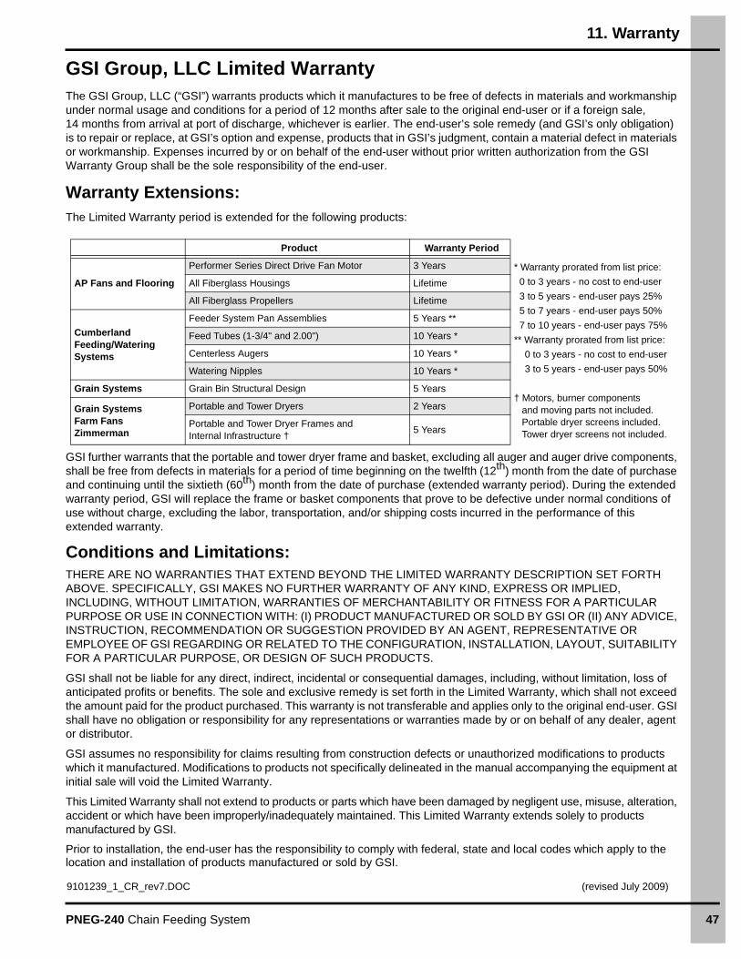
Warranty Extensions:The Limited Warranty period is extended for the following products:
GSI further warrants that the portable and tower dryer frame and basket, excluding all auger and auger drive components, shall be free from defects in materials for a period of time beginning on the twelfth (12th) month from the date of purchase and continuing until the sixtieth (60th) month from the date of purchase (extended warranty period). During the extended warranty period, GSI will replace the frame or basket components that prove to be defective under normal conditions of use without charge, excluding the labor, transportation, and/or shipping costs incurred in the performance of this extended warranty.
Conditions and Limitations:THERE ARE NO WARRANTIES THAT EXTEND BEYOND THE LIMITED WARRANTY DESCRIPTION SET FORTH ABOVE. SPECIFICALLY, GSI MAKES NO FURTHER WARRANTY OF ANY KIND, EXPRESS OR IMPLIED, INCLUDING, WITHOUT LIMITATION, WARRANTIES OF MERCHANTABILITY OR FITNESS FOR A PARTICULAR PURPOSE OR USE IN CONNECTION WITH: (I) PRODUCT MANUFACTURED OR SOLD BY GSI OR (II) ANY ADVICE, INSTRUCTION, RECOMMENDATION OR SUGGESTION PROVIDED BY AN AGENT, REPRESENTATIVE OR EMPLOYEE OF GSI REGARDING OR RELATED TO THE CONFIGURATION, INSTALLATION, LAYOUT, SUITABILITY FOR A PARTICULAR PURPOSE, OR DESIGN OF SUCH PRODUCTS.
GSI shall not be liable for any direct, indirect, incidental or consequential damages, including, without limitation, loss of anticipated profits or benefits. The sole and exclusive remedy is set forth in the Limited Warranty, which shall not exceed the amount paid for the product purchased. This warranty is not transferable and applies only to the original end-user. GSI shall have no obligation or responsibility for any representations or warranties made by or on behalf of any dealer, agent or distributor.
GSI assumes no responsibility for claims resulting from construction defects or unauthorized modifications to products which it manufactured. Modifications to products not specifically delineated in the manual accompanying the equipment at initial sale will void the Limited Warranty.
This Limited Warranty shall not extend to products or parts which have been damaged by negligent use, misuse, alteration, accident or which have been improperly/inadequately maintained. This Limited Warranty extends solely to products manufactured by GSI.
Prior to installation, the end-user has the responsibility to comply with federal, state and local codes which apply to the location and installation of products manufactured or sold by GSI.
Product Warranty Period
AP Fans and Flooring
Performer Series Direct Drive Fan Motor 3 Years * Warranty prorated from list price:
0 to 3 years - no cost to end-user
3 to 5 years - end-user pays 25%
5 to 7 years - end-user pays 50%
7 to 10 years - end-user pays 75%
** Warranty prorated from list price:
0 to 3 years - no cost to end-user
3 to 5 years - end-user pays 50%
† Motors, burner components and moving parts not included. Portable dryer screens included. Tower dryer screens not included.
All Fiberglass Housings Lifetime
All Fiberglass Propellers Lifetime
Cumberland Feeding/Watering Systems
Feeder System Pan Assemblies 5 Years **
Feed Tubes (1-3/4" and 2.00") 10 Years *
Centerless Augers 10 Years *
Watering Nipples 10 Years *
Grain Systems Grain Bin Structural Design 5 Years
Grain SystemsFarm FansZimmerman
Portable and Tower Dryers 2 Years
Portable and Tower Dryer Frames and Internal Infrastructure †
5 Years
9101239_1_CR_rev7.DOC (revised July 2009)

Copyright © 2010 by GroupPrinted in the USA
This equipment shall be installed in accordance with the current installation codes and applicable
regulations which should be carefully followed in all cases. Authorities having jurisdiction should be
consulted before installations are made.
1004 E. Illinois St. Assumption, IL 62510-0020
Phone: 1-217-226-4421 Fax: 1-217-226-4420
www.gsiag.com