
الرفوف المعدنية - شركة نيروخ لصناعة القبانات والموازين - الخليل
Upload
hossam-shafiq-iiCategory
view
314download
7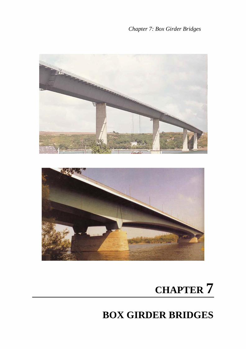
Chapter 7: Box Girder Bridges
CHAPTER 7
BOX GIRDER BRIDGES

Steel Bridges
CHAPTER 7
BOX GIRDER BRIDGES 7.1 INTRODUCTION Box girders have two properties which can offer substantial advantages in certain circumstances over plate girders:
1- they possess torsional stiffness, and 2- their flanges can be made much wider, thus solving the problem of
providing a large steel area within a narrow width of plate. As well as being advantageous in the completed condition of the bridge, these properties can also make box girder bridges simpler in principle to erect. The problems of lateral torsional buckling, for example, do not arise, and if a bridge is to be erected by cantilevering, very long unsupported spans can be adopted. For medium span bridges, box girders offer an attractive form of construction. Design and construction techniques already popular and common for plate girder bridges can be utilized to produce box girder bridges of clean appearance whilst maintaining relative simplicity and speedy construction procedures. The scope of application of such designs could cover the medium span range from about 45 m to 100 m. Until 1940 the structural possibilities for box girders were limited; most bridge girders were assembled from rolled sections, plates and riveted connections. With the development of electric welding and precision flame cutting, the structural possibilities increased enormously. It is now possible to design large welded units in a more economical way.
Chapter 7: Box Girder Bridges 277
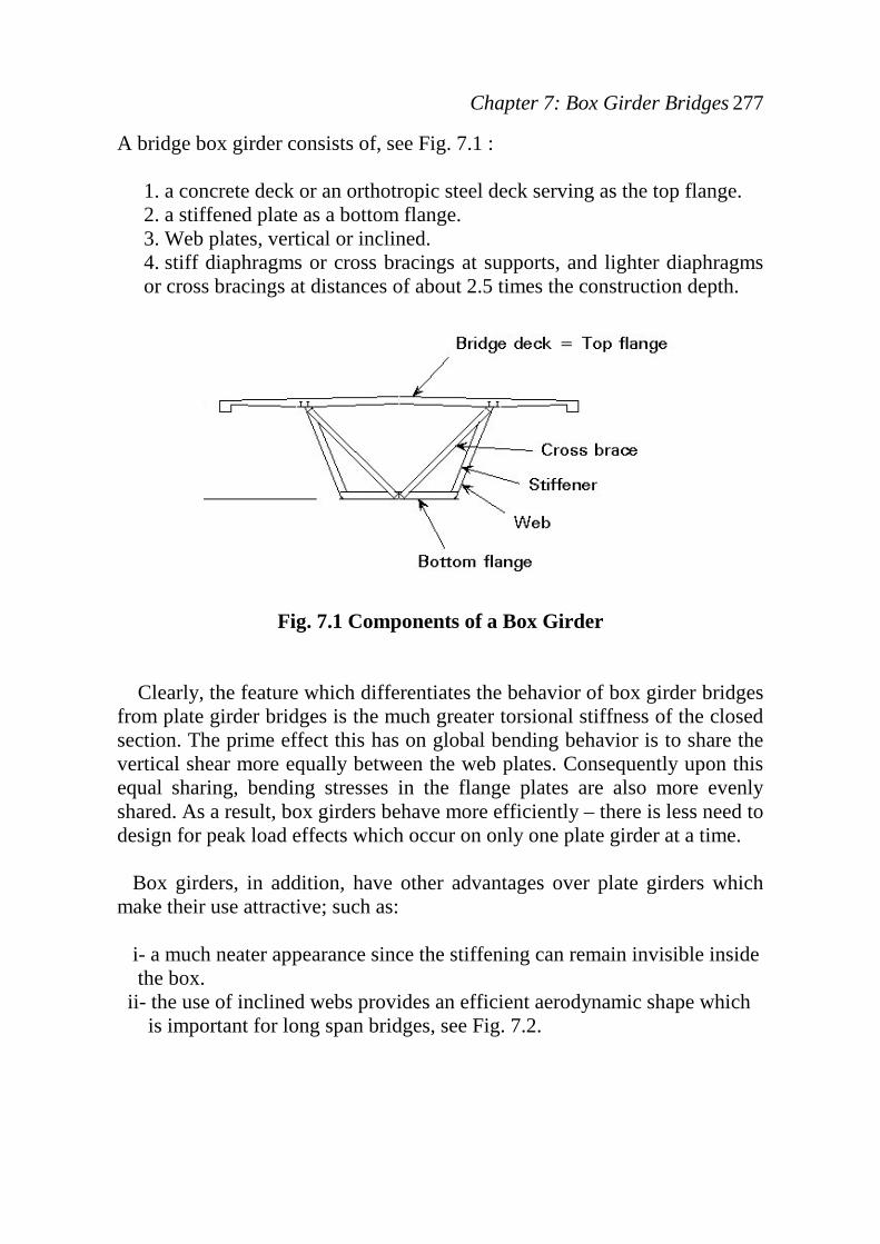
A bridge box girder consists of, see Fig. 7.1 :
1. a concrete deck or an orthotropic steel deck serving as the top flange. 2. a stiffened plate as a bottom flange. 3. Web plates, vertical or inclined. 4. stiff diaphragms or cross bracings at supports, and lighter diaphragms or cross bracings at distances of about 2.5 times the construction depth.
Fig. 7.1 Components of a Box Girder
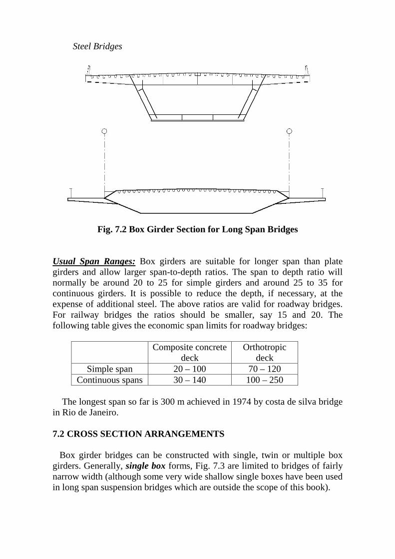
Clearly, the feature which differentiates the behavior of box girder bridges from plate girder bridges is the much greater torsional stiffness of the closed section. The prime effect this has on global bending behavior is to share the vertical shear more equally between the web plates. Consequently upon this equal sharing, bending stresses in the flange plates are also more evenly shared. As a result, box girders behave more efficiently – there is less need to design for peak load effects which occur on only one plate girder at a time. Box girders, in addition, have other advantages over plate girders which make their use attractive; such as: i- a much neater appearance since the stiffening can remain invisible inside the box. ii- the use of inclined webs provides an efficient aerodynamic shape which is important for long span bridges, see Fig. 7.2.
Steel Bridges
Fig. 7.2 Box Girder Section for Long Span Bridges
UUUsual Span Ranges: UU Box girders are suitable for longer span than plate girders and allow larger span-to-depth ratios. The span to depth ratio will normally be around 20 to 25 for simple girders and around 25 to 35 for continuous girders. It is possible to reduce the depth, if necessary, at the expense of additional steel. The above ratios are valid for roadway bridges. For railway bridges the ratios should be smaller, say 15 and 20. The following table gives the economic span limits for roadway bridges:
Composite concrete deck
Orthotropic deck
Simple span 20 – 100 70 – 120 Continuous spans 30 – 140 100 – 250
The longest span so far is 300 m achieved in 1974 by costa de silva bridge
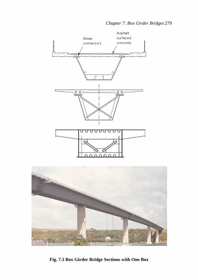
in Rio de Janeiro. 7.2 CROSS SECTION ARRANGEMENTS Box girder bridges can be constructed with single, twin or multiple box girders. Generally, single box forms, Fig. 7.3 are limited to bridges of fairly narrow width (although some very wide shallow single boxes have been used in long span suspension bridges which are outside the scope of this book).
Chapter 7: Box Girder Bridges 279
Fig. 7.3 Box Girder Bridge Sections with One Box

Steel Bridges
Typical width of the boxes themselves would be between about 2 m and 4 m although both wider and narrower boxes have been used (it is common practice for the box to be made complete in the fabricator's works in order to minimize site assembly; boxes much in excess of 4 m in width, whilst perfectly practical to design and fabricate, can cause problems in transport). Cantilever brackets would normally be made between about 3 m and 5 m long, and cross girders between 10 m and 15 m in length (again, of course, these are not absolute limits, merely common practice). Using these figures gives total bridge widths of between 8 m and 14 m for a single box with cantilevers either side, and between 20 m and 33 m for twin boxes with cross girders between them and cantilevers outside the outer webs. The most usual layout for bridges of medium span consists of two longitudinal box girders, interconnected by cross girders which are usually fabricated plate girders and having also fabricated plate cantilever brackets projecting beyond their outer webs (Fig.7.4). The deck can either be of reinforced concrete or of orthotropic stiffened steel plate. If the deck is of concrete, it will act compositely with the main box girders and also with the transverse plate girders and cantilevers; if of steel plate, it forms parts of the flanges of the boxes. As general guidance, a reinforced concrete deck would be used if the bridge span is less than about 150 m, and an orthotropic steel deck if it is over 200 m. Between these limits consideration should be given to either form of construction. It must always be remembered that special considerations may require the use of a particular type of deck outside the suggested span ranges quoted above. An alternative solution to two lane bridges involves carrying each lane on its own individual single box girder. Such a layout has a number of advantages in addition to overcoming the problem of fitting a cross girder accurately between two longitudinal girders present in plate girder bridges. The use of separate structures for the two lanes of a dual lane bridge ensures that even if one superstructure is damaged or even destroyed the bridge can continue to be used whilst it is being repaired or replaced, by diverting two way traffic on to the remaining structure.
Multiple boxes are needed for wider roads. Alternatively, wide roads can be carried on twin box sections with cross girders, so that the deck slab works longitudinally, rather than transversally between the lines of the box webs.
Chapter 7: Box Girder Bridges 281
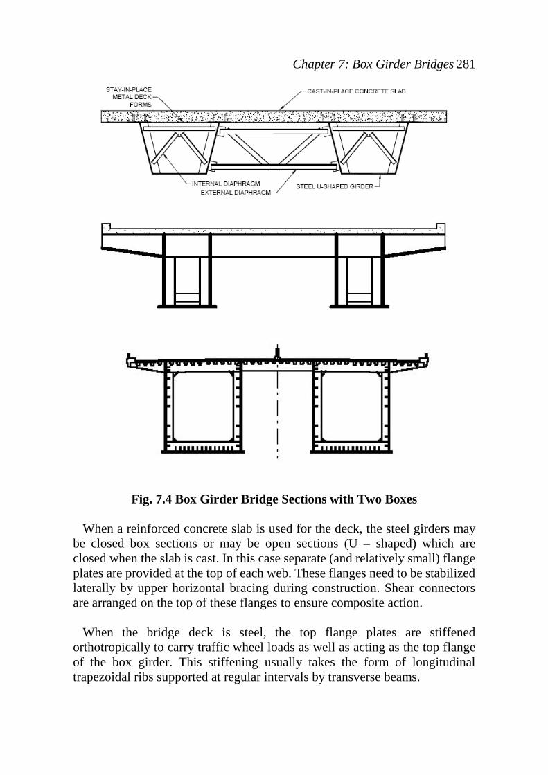
Fig. 7.4 Box Girder Bridge Sections with Two Boxes
When a reinforced concrete slab is used for the deck, the steel girders may be closed box sections or may be open sections (U – shaped) which are closed when the slab is cast. In this case separate (and relatively small) flange plates are provided at the top of each web. These flanges need to be stabilized laterally by upper horizontal bracing during construction. Shear connectors are arranged on the top of these flanges to ensure composite action. When the bridge deck is steel, the top flange plates are stiffened orthotropically to carry traffic wheel loads as well as acting as the top flange of the box girder. This stiffening usually takes the form of longitudinal trapezoidal ribs supported at regular intervals by transverse beams.
Steel Bridges
In the descriptions above it has been implicitly assumed that the steel boxes themselves are of rectangular cross-section. Whilst this is probably the commonest cross-section, there is no reason in principle why the webs should be vertical; many boxes from the smallest to the largest have had sloping webs. In some cases of very large boxes this provides an expedient by which a two lane deck maybe carried on a single box. The loading on the deck may be transferred to the webs through deck slab action or through cross girders inside the box bearing on transverse stiffeners on the webs. If the depth of the web varies according to the bending moment requirements, the use of non-vertical webs should be avoided since this combination would give rise to extremely awkward detailing problems, and could sometimes result in ugly appearance of the bridge 7.3 BEHAVIOUR OF BOX GIRDER BRIDGES 7.3.1 Structural Analysis
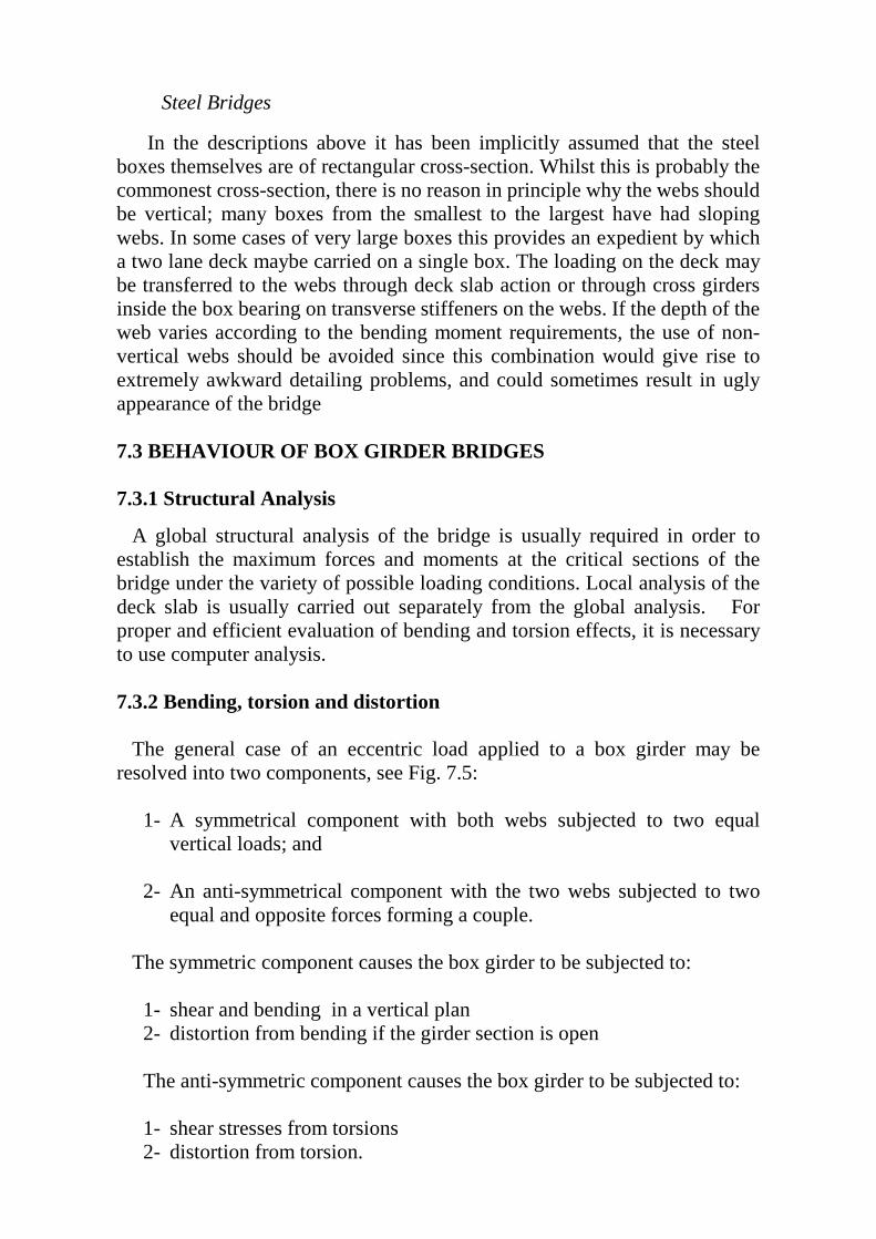
A global structural analysis of the bridge is usually required in order to establish the maximum forces and moments at the critical sections of the bridge under the variety of possible loading conditions. Local analysis of the deck slab is usually carried out separately from the global analysis. For proper and efficient evaluation of bending and torsion effects, it is necessary to use computer analysis. 7.3.2 Bending, torsion and distortion The general case of an eccentric load applied to a box girder may be resolved into two components, see Fig. 7.5:
1- A symmetrical component with both webs subjected to two equal vertical loads; and
2- An anti-symmetrical component with the two webs subjected to two
equal and opposite forces forming a couple.
The symmetric component causes the box girder to be subjected to:
1- shear and bending in a vertical plan 2- distortion from bending if the girder section is open The anti-symmetric component causes the box girder to be subjected to: 1- shear stresses from torsions 2- distortion from torsion.
Chapter 7: Box Girder Bridges 283
Fig. 7.5 Effect of Eccentric Loading on Box Girder Sections:

Steel Bridges
7.4 Effect Bending
Bending moments produce longitudinal normal stresses in the box girder given by:
yI
Mfx
x=
Since box girders contain wide flanges, the distribution of the bending stresses is non-uniform because the flange distorts in its own plane; i.e., plane sections do not remain plane. This phenomenon is known as "Shear Lag".
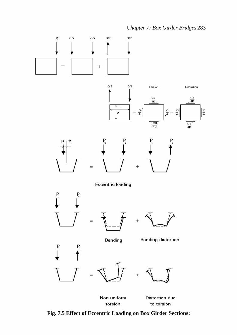
Fig. 7.6 Actual Bending Stress Distribution in a Box Girder. 7.4.1 Shear Lag Phenomenon When the axial load is fed into a wide flange by shear from the webs, the flange distorts in its plane and plane sections do not remain plane. The resulting stress distribution in the flange is not uniform as shown in Fig. 7.6. In very wide flanges, shear lag effects have to be taken into account for the verification of stresses, especially for short spans, since it causes the longitudinal stress at a flange/web intersection to exceed the mean stress in the flange. Shear lag can be allowed for in the elementary theory of bending, by using an effective flange breadth (less than the real breadth) such that the stress in the effective breadth equals the peak stress in the actual flange, see Fig.7.7. This effective flange breadth depends on the ratio of width to span.
Chapter 7: Box Girder Bridges 285
Fig. 7.7 Effective breadth for shear lag effects The effective width is a function of the ratio of the span L to the width b of the box, the cross-sectional area of the stress carrying stiffeners, and the type and position of loading. For continuous girders, the effective widths are obtained separately for the individual equivalent simple spans between the points of inflection. Fortunately, in most situations the span/breadth ratio is not sufficiently large to cause more than 10-20% increase in peak stress, on account of shear lag. According to British Standards UBS5400 : 3/2000: U The effective width bRBeRB should be taken as follows: a) bRBeRB = ψb for portions between webs: where b = half the distance between centers of webs measured along the mid-plane of the flange plate; b) bRBeRB = kψb for portions projecting beyond an outer web; where b = distance from the free edge of the projecting portion to the centre of the outer web; measured along the mid-plane of the flange plate; k = (1 – 0.15b/L); L = span of a beam between centers of support, or in the case of a cantilever beam, between the support and the free end;
Steel Bridges
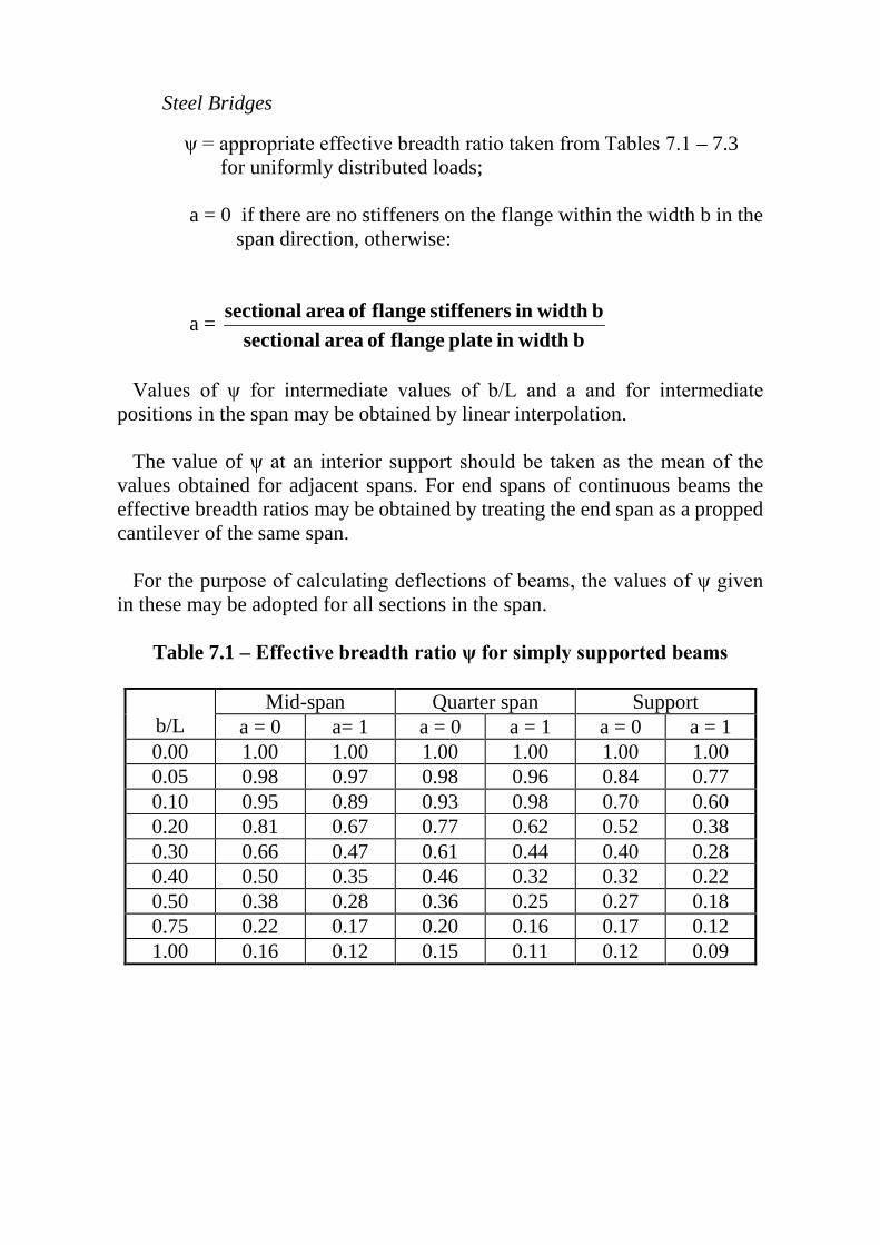
ψ = appropriate effective breadth ratio taken from Tables 7.1 – 7.3 for uniformly distributed loads; a = 0 if there are no stiffeners on the flange within the width b in the span direction, otherwise:
a = b widthin plate flange of area sectional
b widthin stiffeners flange of area sectional
Values of ψ for intermediate values of b/L and a and for intermediate positions in the span may be obtained by linear interpolation. The value of ψ at an interior support should be taken as the mean of the values obtained for adjacent spans. For end spans of continuous beams the effective breadth ratios may be obtained by treating the end span as a propped cantilever of the same span. For the purpose of calculating deflections of beams, the values of ψ given in these may be adopted for all sections in the span.
Table 7.1 – Effective breadth ratio ψ for simply supported beams
b/L Mid-span Quarter span Support
a = 0 a= 1 a = 0 a = 1 a = 0 a = 1 0.00 1.00 1.00 1.00 1.00 1.00 1.00 0.05 0.98 0.97 0.98 0.96 0.84 0.77 0.10 0.95 0.89 0.93 0.98 0.70 0.60 0.20 0.81 0.67 0.77 0.62 0.52 0.38 0.30 0.66 0.47 0.61 0.44 0.40 0.28 0.40 0.50 0.35 0.46 0.32 0.32 0.22 0.50 0.38 0.28 0.36 0.25 0.27 0.18 0.75 0.22 0.17 0.20 0.16 0.17 0.12 1.00 0.16 0.12 0.15 0.11 0.12 0.09
Chapter 7: Box Girder Bridges 287
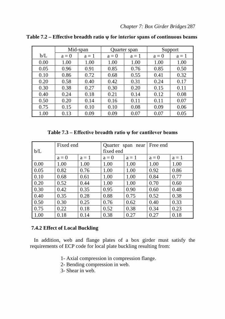
Table 7.2 – Effective breadth ratio ψ for interior spans of continuous beams
b/L
Mid-span Quarter span Support a = 0 a = 1 a = 0 a = 1 a = 0 a = 1
0.00 1.00 1.00 1.00 1.00 1.00 1.00 0.05 0.96 0.91 0.85 0.76 0.85 0.50 0.10 0.86 0.72 0.68 0.55 0.41 0.32 0.20 0.58 0.40 0.42 0.31 0.24 0.17 0.30 0.38 0.27 0.30 0.20 0.15 0.11 0.40 0.24 0.18 0.21 0.14 0.12 0.08 0.50 0.20 0.14 0.16 0.11 0.11 0.07 0.75 0.15 0.10 0.10 0.08 0.09 0.06 1.00 0.13 0.09 0.09 0.07 0.07 0.05
Table 7.3 – Effective breadth ratio ψ for cantilever beams
b/L
Fixed end Quarter span near fixed end
Free end
a = 0 a = 1 a = 0 a = 1 a = 0 a = 1 0.00 1.00 1.00 1.00 1.00 1.00 1.00 0.05 0.82 0.76 1.00 1.00 0.92 0.86 0.10 0.68 0.61 1.00 1.00 0.84 0.77 0.20 0.52 0.44 1.00 1.00 0.70 0.60 0.30 0.42 0.35 0.95 0.90 0.60 0.48 0.40 0.35 0.28 0.88 0.75 0.52 0.38 0.50 0.30 0.25 0.76 0.62 0.40 0.33 0.75 0.22 0.18 0.52 0.38 0.34 0.23 1.00 0.18 0.14 0.38 0.27 0.27 0.18
7.4.2 Effect of Local Buckling In addition, web and flange plates of a box girder must satisfy the requirements of ECP code for local plate buckling resulting from:
1- Axial compression in compression flange. 2- Bending compression in web. 3- Shear in web.
Steel Bridges
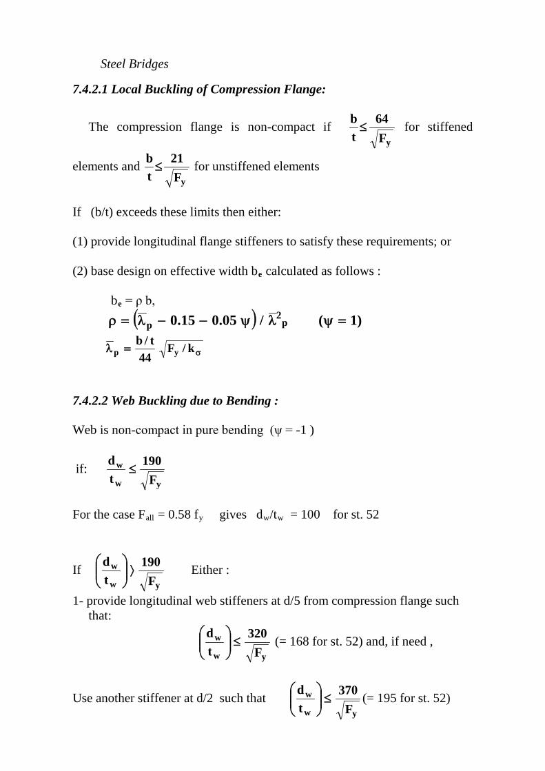
7.4.2.1 Local Buckling of Compression Flange:
The compression flange is non-compact if yF
64tb≤ for stiffened
elements and yF
21tb≤ for unstiffened elements
If (b/t) exceeds these limits then either: (1) provide longitudinal flange stiffeners to satisfy these requirements; or (2) base design on effective width bRBeRB calculated as follows : bRBeRB = ρ b, ( ) )1(/05.015.0 p
2p =ψλψ−−λ=ρ
σ=λ k/F44
t/byp
7.4.2.2 Web Buckling due to Bending : Web is non-compact in pure bending (ψ = -1 )
if: yw
w
F190
td
≤
For the case FRBallRB = 0.58 fRByRB gives dRBwRB/tRBwRB = 100 for st. 52
If yw
w
F190
td
⟩
Either :
1- provide longitudinal web stiffeners at d/5 from compression flange such that:
yw
w
F320
td
≤
(= 168 for st. 52) and, if need ,
Use another stiffener at d/2 such that yw
w
F370
td
≤
(= 195 for st. 52)
Chapter 7: Box Girder Bridges 289
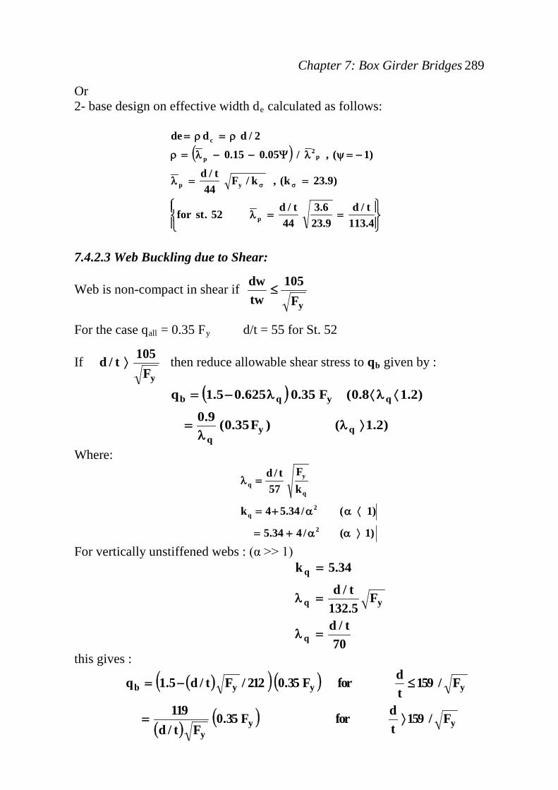
Or 2- base design on effective width dRBeRB calculated as follows:
( )
==λ
==λ
−=ψλΨ−−λ=ρ
ρ=ρ=
σσ
4.113t/d
9.236.3
44t/d52.stfor
)9.23k(,k/F44
t/d
)1(,/05.015.0
2/ddde
p
yp
p2
p
c
7.4.2.3 Web Buckling due to Shear:
Web is non-compact in shear if yF
105twdw
≤
For the case qRBallRB = 0.35 FRByRB d/t = 55 for St. 52
If yF
105t/d ⟩ then reduce allowable shear stress to qRBbRB given by :
( )
)2.1()F35.0(9.0
)2.18.0(F35.0625.05.1q
qyq
qyqb
⟩λλ
=
⟨λ⟨λ−=
Where:
)1(/434.5
)1(/34.54k
kF
57t/d
2
2q
q
yq
⟩αα+=
⟨αα+=
=λ
For vertically unstiffened webs : (α >> 1)
70t/d
F5.132t/d
34.5k
q
yq
q
=λ
=λ
=
this gives :
( )( ) ( )
( )( ) yy
y
yyyb
F/159tdforF35.0
Ft/d119
F/159tdforF35.0212/Ft/d5.1q
⟩=
≤−=

Steel Bridges
7.4.3 Combined Shear & Bending In general, any cross-section of a box girder will be subjected to bending moment in addition to shear. This combination makes the stress conditions in the girder web considerably more complex. The stresses from the bending moment will combine with the shear stresses to give a lower buckling load. The interaction between shear and bending can be conveniently represented by the diagram shown in Fig. 7.8, where the allowable bending stress is plotted on the vertical axis and the allowable buckling shear stress of the girder is plotted horizontally. The interaction represents a failure envelope, with any point lying on the curve defining the co-existent values of shear and bending that the girder can just sustain. The equation representing this interaction diagram is :
( )[ ] yba c tb Fq/q3 6.08.0F −=
The interaction diagram can be considered in 3 regions. In region AB, the applied shear stress qRBactRB is low (< 0.6 qRBbRB) and the girder can sustain the full bending stress FRBbRB based on the effective width bRBeffRB for the compression flange. At the other extreme of the interaction diagram in region CD, the applied shear stress is high (=qRBbRB) then the allowable bending stress is reduced to 0.44 FRByRB to allow for the high shear. In the intermediate region BC the allowable bending stress is reduced linearly from 0.58 FRByRB to 0.44 FRByRB.
Shear Stress
Ben
ding
Stre
ss
0.44 Fy
0.58 Fy
0.6 q b q b
A B
C
D
Fig. 7.8 Interaction between Shear and Bending
Chapter 7: Box Girder Bridges 291
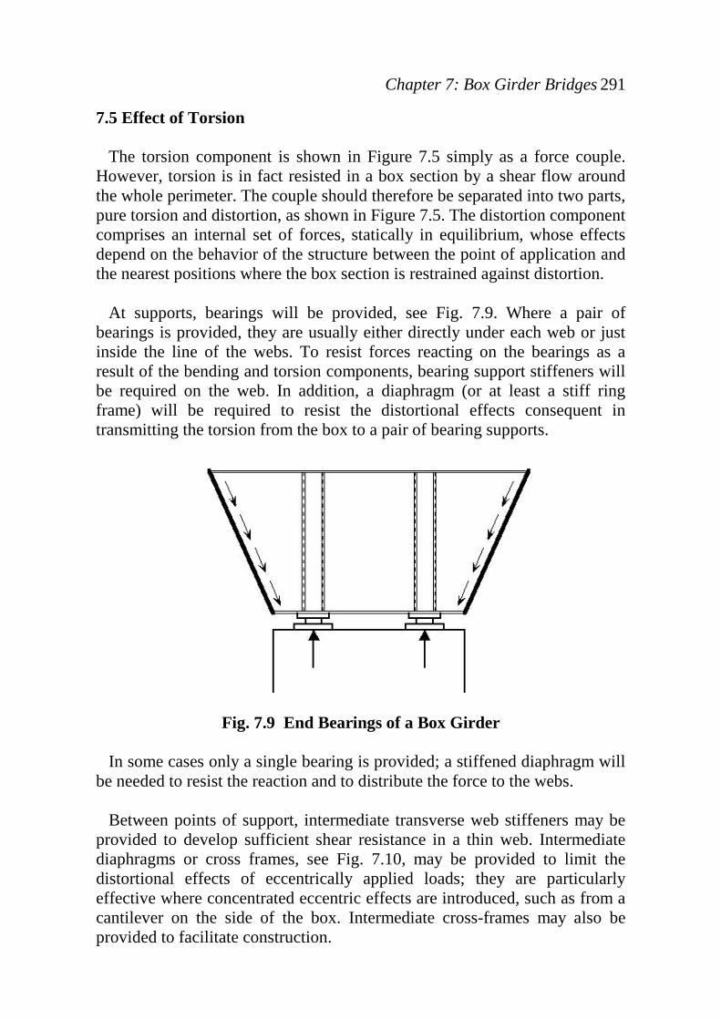
7.5 Effect of Torsion The torsion component is shown in Figure 7.5 simply as a force couple. However, torsion is in fact resisted in a box section by a shear flow around the whole perimeter. The couple should therefore be separated into two parts, pure torsion and distortion, as shown in Figure 7.5. The distortion component comprises an internal set of forces, statically in equilibrium, whose effects depend on the behavior of the structure between the point of application and the nearest positions where the box section is restrained against distortion. At supports, bearings will be provided, see Fig. 7.9. Where a pair of bearings is provided, they are usually either directly under each web or just inside the line of the webs. To resist forces reacting on the bearings as a result of the bending and torsion components, bearing support stiffeners will be required on the web. In addition, a diaphragm (or at least a stiff ring frame) will be required to resist the distortional effects consequent in transmitting the torsion from the box to a pair of bearing supports.
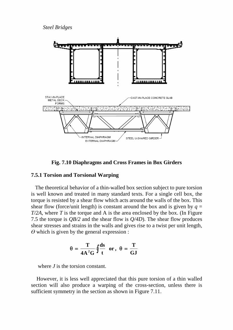
Fig. 7.9 End Bearings of a Box Girder In some cases only a single bearing is provided; a stiffened diaphragm will be needed to resist the reaction and to distribute the force to the webs. Between points of support, intermediate transverse web stiffeners may be provided to develop sufficient shear resistance in a thin web. Intermediate diaphragms or cross frames, see Fig. 7.10, may be provided to limit the distortional effects of eccentrically applied loads; they are particularly effective where concentrated eccentric effects are introduced, such as from a cantilever on the side of the box. Intermediate cross-frames may also be provided to facilitate construction.
Steel Bridges
Fig. 7.10 Diaphragms and Cross Frames in Box Girders
7.5.1 Torsion and Torsional Warping The theoretical behavior of a thin-walled box section subject to pure torsion is well known and treated in many standard texts. For a single cell box, the torque is resisted by a shear flow which acts around the walls of the box. This shear flow (force/unit length) is constant around the box and is given by q = T/2A, where T is the torque and A is the area enclosed by the box. (In Figure 7.5 the torque is QB/2 and the shear flow is Q/4D). The shear flow produces shear stresses and strains in the walls and gives rise to a twist per unit length, Ө which is given by the general expression :
∫ =θ=θGJT,or
tds
GA4T
2
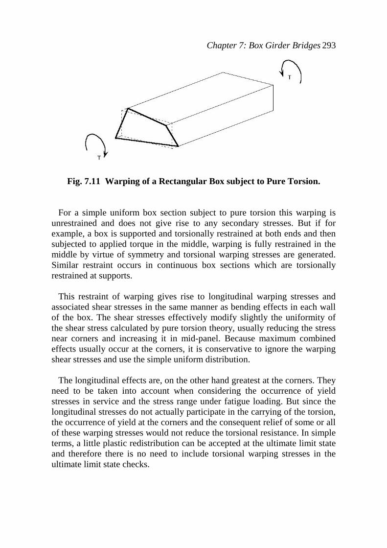
where J is the torsion constant. However, it is less well appreciated that this pure torsion of a thin walled section will also produce a warping of the cross-section, unless there is sufficient symmetry in the section as shown in Figure 7.11.
Chapter 7: Box Girder Bridges 293
Fig. 7.11 Warping of a Rectangular Box subject to Pure Torsion. For a simple uniform box section subject to pure torsion this warping is unrestrained and does not give rise to any secondary stresses. But if for example, a box is supported and torsionally restrained at both ends and then subjected to applied torque in the middle, warping is fully restrained in the middle by virtue of symmetry and torsional warping stresses are generated. Similar restraint occurs in continuous box sections which are torsionally restrained at supports. This restraint of warping gives rise to longitudinal warping stresses and associated shear stresses in the same manner as bending effects in each wall of the box. The shear stresses effectively modify slightly the uniformity of the shear stress calculated by pure torsion theory, usually reducing the stress near corners and increasing it in mid-panel. Because maximum combined effects usually occur at the corners, it is conservative to ignore the warping shear stresses and use the simple uniform distribution. The longitudinal effects are, on the other hand greatest at the corners. They need to be taken into account when considering the occurrence of yield stresses in service and the stress range under fatigue loading. But since the longitudinal stresses do not actually participate in the carrying of the torsion, the occurrence of yield at the corners and the consequent relief of some or all of these warping stresses would not reduce the torsional resistance. In simple terms, a little plastic redistribution can be accepted at the ultimate limit state and therefore there is no need to include torsional warping stresses in the ultimate limit state checks.
Steel Bridges
7.5.2 Distortion When torsion is applied directly around the perimeter of a box section, by forces exactly equal to the shear flow in each of the sides of the box, there is no tendency for the cross section to change its shape. If torsion is not applied in this manner, a diaphragm or stiff frame might be provided at the position where the force couple is applied to ensure that the section remains square and that torque is in fact fed into the box walls as a shear flow around the perimeter. The diaphragm or frame is then subject to a set of distortional forces as shown in Figure 7.5.
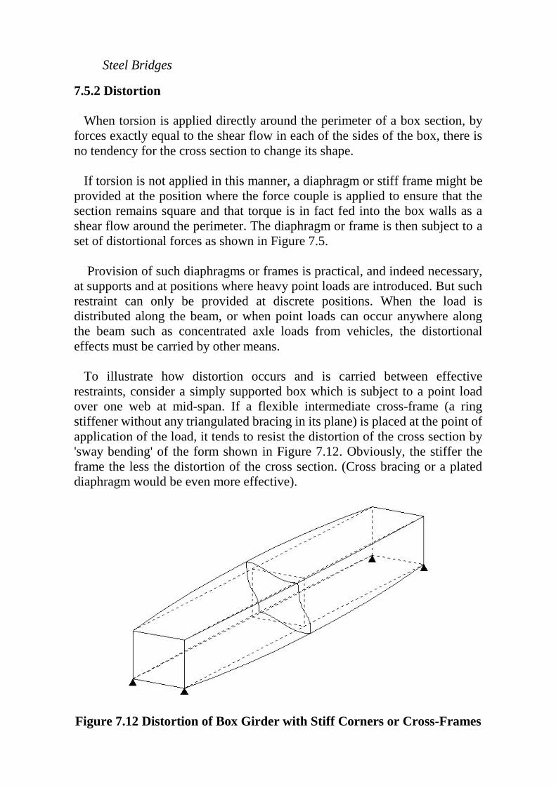
Provision of such diaphragms or frames is practical, and indeed necessary, at supports and at positions where heavy point loads are introduced. But such restraint can only be provided at discrete positions. When the load is distributed along the beam, or when point loads can occur anywhere along the beam such as concentrated axle loads from vehicles, the distortional effects must be carried by other means. To illustrate how distortion occurs and is carried between effective restraints, consider a simply supported box which is subject to a point load over one web at mid-span. If a flexible intermediate cross-frame (a ring stiffener without any triangulated bracing in its plane) is placed at the point of application of the load, it tends to resist the distortion of the cross section by 'sway bending' of the form shown in Figure 7.12. Obviously, the stiffer the frame the less the distortion of the cross section. (Cross bracing or a plated diaphragm would be even more effective).
Figure 7.12 Distortion of Box Girder with Stiff Corners or Cross-Frames

Chapter 7: Box Girder Bridges 295
The bending of cross-frames and the walls of a box, as a result of the distortional forces, produces transverse distortional bending stresses in the box section. In general the distortional behavior depends on interaction between the two sorts of behavior, the warping and the transverse distortional bending. The behavior has been demonstrated to be analogous to that of a beam on an elastic foundation, BEF, representing the transverse distortional bending resistance. The BEF model is used as the basis for the rules in Appendix B of BS 5400 Part 3 for calculating distortion and warping stresses in box girders. This Appendix is shown in the next section. It must be emphasized that distortional effects are UUprimaryUU effects – they are an essential part of the means of carrying loads applied other than at stiff diaphragms – and they should not be ignored.
Steel Bridges
7.6 DESIGN EXAMPLE:
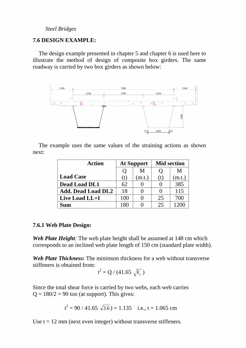
The design example presented in chapter 5 and chapter 6 is used here to illustrate the method of design of composite box girders. The same roadway is carried by two box girders as shown below:
1480
1500 7000
2150 2700 2150
1500
320
220
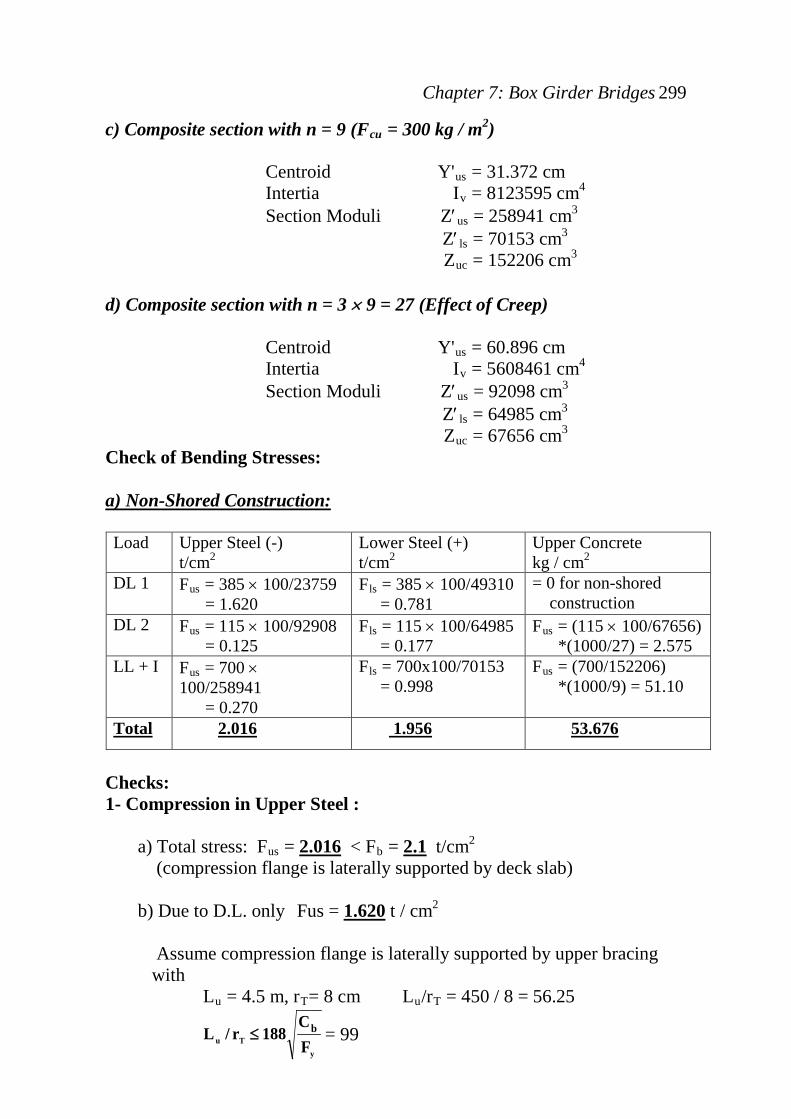
2525 1450 The example uses the same values of the straining actions as shown
next:
7.6.1 Web Plate Design: Web Plate Height: The web plate height shall be assumed at 148 cm which corresponds to an inclined web plate length of 150 cm (standard plate width). Web Plate Thickness: The minimum thickness for a web without transverse stiffeners is obtained from: t P
P
2PP = Q / (41.65 yF )
Since the total shear force is carried by two webs, each web carries Q = 180/2 = 90 ton (at support). This gives: t P
P
2PP = 90 / 41.65 6.3 ) = 1.135 i.e., t = 1.065 cm
Use t = 12 mm (next even integer) without transverse stiffeners.
Action Load Case
At Support Mid section Q (t)
M (m.t.)
Q (t)
M (m.t.)
Dead Load DL1 62 0 0 385 Add. Dead Load DL2 18 0 0 115 Live Load LL+I 100 0 25 700 Sum 180 0 25 1200

Chapter 7: Box Girder Bridges 297
Check of web buckling due to shear: Allowable Buckling Shear Stress = qRBb RB= ( 119 / (d/t) yF ) (0.35 FRByRB) qRBb RB= ( 119 / (150/1.2) yF ) (0.35 FRByRB) = 0.632 t/cmP
P
2PP
Actual Shear Stress:
i.e., Web Plate is safe against buckling due to shear at support
.)K.O(qcm/t514.02.1146
90q b2
act <=×
=

Steel Bridges
7.6.2 Main Girder Design: The section properties of the proposed cross section are as follows: The following section is assumed: a) Two Webs 1500 × 12 b) Top Flange 300 × 12 (bRBfRB / 2tRBfRB = 30 / (2 ×1.2) = 12.5 > 21 / yf = 11 (No problem since flange is prevented from local buckling by deck slab) c) Bottom Flange 1500 × 22 UUSection properties are then computed for the following cases: a) Steel section only: Centroid YRBusRB = 99.336 cm Intertia IRBsRB = 2360156 cmP
P
4PP
Section Moduli ZRBusRB = 23759 cmP
P
3PP
ZRBlsRB = 49310 cmP
P
3PP
b) Effective Slab Width: For the exterior web: bRBERRB = b* = UU150UU cm (Side Walk Slab) bRBELRB = smaller of: 1) Span/8 = 27.5 /8 = 3.4375 m 2) Spacing /2 = 2.15/2 = UU1.075UU m governs 3) 6 ts = 6 * 22 = 132 cm For the interior web: bRBERRB = smaller of: 1) Span/8 = 27.5 /8 = 3.4375 m 2) Spacing /2 = 2.15/2 = UU1.075UU m governs 3) 6 ts = 6 * 22 = 132 cm bRBELRB = smaller of: 1) Span/8 = 27.5 /8 = 3.4375 m 2) Spacing /2 = 2.70/2 = 1.35 m 3) 6 ts = 6 * 22 = UU132 UUcm governs Total Effective Slab Width = (150 + 107.5) + (107.5+132) = 497 cm
Chapter 7: Box Girder Bridges 299
c) Composite section with n = 9 (FRBcuRB = 300 kg / m P
P
2PP)
Centroid Y'RBusRB = 31.372 cm Intertia IRBvRB = 8123595 cmP
P
4PP
Section Moduli Z′RBusRB = 258941 cmP
P
3PP
Z′RBlsRB = 70153 cmP
P
3
ZRBucRB = 152206 cmP
P
3PP
d) Composite section with n = 3 × 9 = 27 (Effect of Creep)
Centroid Y'RBusRB = 60.896 cm Intertia IRBvRB = 5608461 cmP
P
4PP
Section Moduli Z′RBusRB = 92098 cmP
P
3PP
Z′RBlsRB = 64985 cmP
P
3
ZRBucRB = 67656 cmP
P
3PP
Check of Bending Stresses: UUa) Non-Shored Construction: Load Upper Steel (-)
t/cmP
P
2PP
Lower Steel (+) t/cmP
P
2PP
Upper Concrete kg / cmP
P
2PP
DL 1 FRBusRB = 385 × 100/23759 = 1.620
FRBlsRB = 385 × 100/49310 = 0.781
= 0 for non-shored construction
DL 2 FRBusRB = 115 × 100/92908 = 0.125
FRBlsRB = 115 × 100/64985 = 0.177
FRBusRB = (115 × 100/67656) *(1000/27) = 2.575
LL + I FRBusRB = 700 × 100/258941 = 0.270
FRBlsRB = 700x100/70153 = 0.998
FRBusRB = (700/152206) *(1000/9) = 51.10
UUTotalUU UU2.016 UU UU 1.956UU UU53.676 UU
Checks: 1- Compression in Upper Steel : a) Total stress: FRBusRB = UU2.016UU < FRBbRB = UU2.1UU t/cmP
P
2PP
(compression flange is laterally supported by deck slab) b) Due to D.L. only Fus = UU1.620UU t / cmP
P
2PP
Assume compression flange is laterally supported by upper bracing with LRBuRB = 4.5 m, rRBTRB= 8 cm LRBuRB/rRBTRB = 450 / 8 = 56.25
y
Tu FC
188r/L b≤ = 99
Steel Bridges
yyb
5
y2
Tu F58.0F)C10x176.1F)r/L(
64.0(2ltbF ≤−= = UU1.955UU t/cm2
FRBusRB < FRBLTBRP
BP
PPO.K.
2. Tension in Upper Steel :
a) Total Tension: fRBlsRB = 1.956 < FRBbRB = 2.10 t/cmP
P
2PP
b) Fatigue fRBsrRB = 0.5 × 0.998 = 0.499 < FRBsrRB = 1.02 t/cmP
P
2PP
{The allowable fatigue stress range (FRBsrRB) is obtained as follows: * From ECP Table 3.1.a: ADTT >2500, Number of cycles = 2 ×10P
P
6PP
Detail Class = B′ (case 4.2 of Table 3.3) Table 3.2 gives FRBsrRB = UU1.02UU t/cmP
P
2PP > fRBsrRB }
3. Compression in Upper Concrete:
fRBucRB = 53.676 < 70 kg/cmP
P
2PP
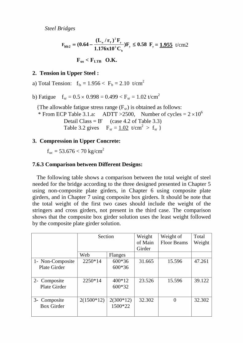
7.6.3 Comparison between Different Designs: The following table shows a comparison between the total weight of steel needed for the bridge according to the three designed presented in Chapter 5 using non-composite plate girders, in Chapter 6 using composite plate girders, and in Chapter 7 using composite box girders. It should be note that the total weight of the first two cases should include the weight of the stringers and cross girders, not present in the third case. The comparison shows that the composite box girder solution uses the least weight followed by the composite plate girder solution. Section Weight
of Main Girder
Weight of Floor Beams
Total Weight
Web Flanges 1- Non-Composite Plate Girder
2250*14 600*36 600*36
31.665 15.596 47.261
2- Composite Plate Girder
2250*14 400*12 600*32
23.526 15.596 39.122
3- Composite Box Girder
2(1500*12) 2(300*12) 1500*22
32.302 0 32.302


