
Ch20 - Wikispacesjluckow.wikispaces.com/file/view/Drawing+Floor+Plans.pdf · Chapter 20 Drawing...
19
525 CHAPTER 20 Drawing Floor Plans Learning Objectives After completing this chapter, you will be able to: Completely describe a floor plan. Draw walls using polylines and lines. Describe and draw additional floor plan symbols. Place floor plan dimensions and notes. Use tag symbols. Create named views that can be recalled instantly. Create multiple viewports in the drawing window. A floor plan consists of wall placement, door and window location, cabinets, plumbing fixtures, detail symbols, and dimensions. To create the floor plan, the building is “cut” at a horizontal cutting plane located at approximately eye level. See Figure 20-1. Consider the cutting plane as a saw cutting horizontally through the building. The top portion of the building is removed, leaving the bottom portion that represents the floor plan. This allows the viewer to see where doors, windows, and cabinets are placed within the building. In a multistory building, each floor is “cut” horizontally to show the layout of each floor. The elevation of the cutting plane can vary, especially if there is a design feature to show in the floor plan. For example, if a single room is two stories high, the cutting plane can be adjusted to show this feature. Drawing Walls Walls are generally drawn as parallel lines, depending on the type of wall construc- tion. In wood frame construction, walls are typically represented as two parallel lines, with the distance between the lines determined by the thickness of the framing members. Common framing members are 4″ thick for a 2 × 4 or 6″ thick for a 2 × 6. In other words, the parallel lines for a 2 × 4 wall are drawn 4″ apart. See Figure 20-2A. Studs are not shown in a wall to reduce clutter in the drawing. In steel construction, wall thickness is drawn similar to that for wood construc- tion. However, structural columns, or “studs”, are often shown inside of the walls so floor plan: A 2D representation of a building layout, as viewed from above. cutting plane: An imaginary plane through an object, such as a building, that cuts away the area to be exposed. 526 Architectural Drafting Using AutoCAD the builder knows where the columns are placed. See Figure 20-2B. In concrete or masonry construction, the distance between the lines is the thickness of the concrete block or slab. If the construction material is concrete, a fill or hatch pattern representing concrete can be applied to the walls. See Figure 20-2C. If brick veneer is used in construction, two additional lines are drawn on the out - side of the wall. These lines represent the brick and airspace between the exterior wall and the brick. Brick can also be drawn with a hatch pattern to represent the material. See Figure 20-2D. Using AutoCAD, you can draw the space between wall lines equal to the exact wall construction materials, if desired. For example, a conventionally framed wood wall with 2 × 6 exterior studs, 1/2″ interior gypsum, 1/2″ exterior sheathing, and 1/2″ exterior siding measures: 5-1/2″ (actual dimension of a 2 × 6 wood stud is 1-1/2″× 5-1/2″) 1/2″ gypsum 1/2″ sheathing + 1/2″ siding 7″ A 2 × 4 interior stud wall with 1/2″ gypsum on each side measures: 3-1/2″ (actual dimension of a 2 × 4 wood stud is 1-1/2″× 3-1/2″) 1/2″ gypsum + 1/2″ gypsum 4-1/2″ Laying Out Exterior Wall Lines To start laying out walls, draw the outer perimeter of the building using the appropriate wall layer, such as Wall or A-WALL-FULL. See Figure 20-3A. This provides Figure 20-1. Floor plans are developed by “cutting off” the top portion of a building and looking straight down at the floor. (3D-DZYN) View 2D Floor Plan Building with the Top Cut Away This sample chapter is for review purposes only. Copyright © The Goodheart-Willcox Co., Inc. All rights reserved.
Transcript of Ch20 - Wikispacesjluckow.wikispaces.com/file/view/Drawing+Floor+Plans.pdf · Chapter 20 Drawing...
525
C H A P T E R 20Drawing Floor Plans
Learning ObjectivesAfter completing this chapter, you will be able to:
Completely describe a floor plan. Draw walls using polylines and lines. Describe and draw additional floor plan symbols. Place floor plan dimensions and notes. Use tag symbols. Create named views that can be recalled instantly. Create multiple viewports in the drawing window.
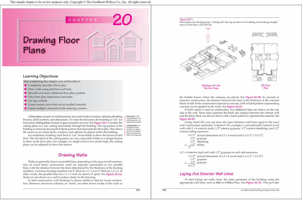
A floor plan consists of wall placement, door and window location, cabinets, plumbing fixtures, detail symbols, and dimensions. To create the floor plan, the building is “cut” at a horizontal cutting plane located at approximately eye level. See Figure 20-1. Consider the cutting plane as a saw cutting horizontally through the building. The top portion of the building is removed, leaving the bottom portion that represents the floor plan. This allows the viewer to see where doors, windows, and cabinets are placed within the building.
In a multistory building, each floor is “cut” horizontally to show the layout of each floor. The elevation of the cutting plane can vary, especially if there is a design feature to show in the floor plan. For example, if a single room is two stories high, the cutting plane can be adjusted to show this feature.
Drawing WallsWalls are generally drawn as parallel lines, depending on the type of wall construc-
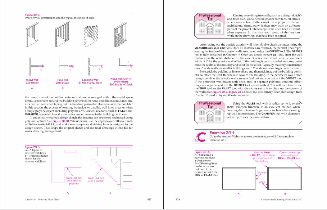
tion. In wood frame construction, walls are typically represented as two parallel lines, with the distance between the lines determined by the thickness of the framing members. Common framing members are 4″ thick for a 2 × 4 or 6″ thick for a 2 × 6. In other words, the parallel lines for a 2 × 4 wall are drawn 4″ apart. See Figure 20-2A.Studs are not shown in a wall to reduce clutter in the drawing.
In steel construction, wall thickness is drawn similar to that for wood construc-tion. However, structural columns, or “studs”, are often shown inside of the walls so
floor plan: A 2D representation of a building layout, as viewed from above.
cutting plane: An imaginary plane through an object, such as a building, that cuts away the area to be exposed.
526 Architectural Drafting Using AutoCAD
the builder knows where the columns are placed. See Figure 20-2B. In concrete or masonry construction, the distance between the lines is the thickness of the concrete block or slab. If the construction material is concrete, a fill or hatch pattern representing concrete can be applied to the walls. See Figure 20-2C.
If brick veneer is used in construction, two additional lines are drawn on the out -side of the wall. These lines represent the brick and airspace between the exterior wall and the brick. Brick can also be drawn with a hatch pattern to represent the material. See Figure 20-2D.
Using AutoCAD, you can draw the space between wall lines equal to the exact wall construction materials, if desired. For example, a conventionally framed wood wall with 2 × 6 exterior studs, 1/2″ interior gypsum, 1/2″ exterior sheathing, and 1/2″exterior siding measures:
5-1/2″ (actual dimension of a 2 × 6 wood stud is 1-1/2″ × 5-1/2″) 1/2″ gypsum 1/2″ sheathing+ 1/2″ siding 7″
A 2 × 4 interior stud wall with 1/2″ gypsum on each side measures: 3-1/2″ (actual dimension of a 2 × 4 wood stud is 1-1/2″ × 3-1/2″) 1/2″ gypsum+ 1/2″ gypsum 4-1/2″
Laying Out Exterior Wall LinesTo start laying out walls, draw the outer perimeter of the building using the
appropriate wall layer, such as Wall or A-WALL-FULL. See Figure 20-3A. This provides
Figure 20-1.Floor plans are developed by “cutting off” the top portion of a building and looking straight down at the floor. (3D-DZYN)
View
2D FloorPlan
Building with theTop Cut Away
This sample chapter is for review purposes only. Copyright © The Goodheart-Willcox Co., Inc. All rights reserved.
Chapter 20 Drawing Floor Plans 527
the overall area of the building exterior that can be arranged within the model space limits. Leave room around the building perimeter for notes and dimensions. Lines and arcs can be used when laying out the building perimeter. However, as explained later in this section, the process of forming the inside, or parallel, wall lines is easier when a single polyline object, including polyline arcs, is used. Use tools such as FILLET and CHAMFER as needed to add rounded or angled corners to the building perimeter.
If you initially created a design sketch, the drawing can be opened and traced using polylines or lines. See Figure 20-3B. When tracing, use the appropriate wall layer, such as Wall or A-WALL-FULL, and make sure a separate sketching layer is assigned to the design sketch. This keeps the original sketch and the final drawings in one file for easier drawing management.
Figure 20-2.Types of wall construction and the typical thickness of each.
Wood Wall2X6 Studs
Steel Wall2X6 Studs
Concrete Wall8" Wide Conc. Block
Wood Wall with 4"Brick Veneer
2X6 Studs 4" BrickA B C D
Figure 20-3.A—A layout of exterior wall lines. B—Tracing a design sketch for the exterior wall lines.
Walls laid outwith lines or
polylines
Walls laid outover a sketch
BA
528 Architectural Drafting Using AutoCAD
ProfessionalTip
Keeping everything in one file, such as a design sketch and floor plan, works well in smaller architectural offices where only a few drafters work on a project. In larger architectural firms, many drafters may work on different parts of the project. These large firms often keep different plans separate. In this way, each group of drafters can work on the drawings that have been assigned.
After laying out the outside exterior wall lines, double-check distances using the MEASUREGEOM or LIST tool. Once all distances are verified, the parallel lines repre-senting the inside of the exterior walls are created using the OFFSET tool. The OFFSETtool is fully explained in Chapter 17. Once you access the OFFSET tool, enter the wall thickness as the offset distance. In the case of residential wood construction, use a width of 6″ for the exterior wall offset. If the building is constructed of masonry, deter-mine the width of the masonry and use it for the offset. Typically, masonry construction uses 8″ wide walls for smaller buildings and 12″ wide walls for larger construction.
Next, pick the polyline or line to offset, and then pick inside of the building perim-eter to offset the wall thickness in toward the building. If the perimeter was drawn using a polyline, the exterior walls are now laid out and you can exit the OFFSET tool. If the perimeter was drawn with lines, arcs, or separate polylines, continue offset-ting each segment and exit the OFFSET tool when finished. You will then have to use the TRIM tool, or the FILLET tool with the radius set to 0, to clean up the corners of the walls. See Figure 20-4. Figure 20-5 shows the preliminary floor plan design from Chapter 16 used to lay out 6″ exterior walls.
ProfessionalTip
Using the FILLET tool with a radius set to 0, or the [Shift] selection function, is an excellent method when forming sharp intersecting corners, such as when cleaning up wall intersections. The CHAMFER tool with distances set to 0 provides the same feature.
Exercise 20-1Go to the student Web site at www.g-wlearning.com/CAD to complete Exercise 20-1.
Figure 20-4.A—Offsetting a polyline produces a clean corner. B—Offsetting lines produces corners that need to be cleaned up with the TRIM or FILLET tool.
Polylines
Lines
Use the TRIMor FILLET tool to clean
up the corners ofthe building
Corner cleaned upafter using the
TRIM or FILLET tool
A B
Chapter 20 Drawing Floor Plans 529
Laying Out Interior Wall LinesOnce the exterior walls are laid out and checked, the interior walls can be drawn.
If the exterior wall lines were drawn using polylines, use the EXPLODE tool to explode the inside exterior wall polyline in order to offset individual lines. Then, use the OFFSET tool to offset the inside exterior wall lines the width of each room. An alterna-tive is to use the COPY tool to copy the lines the correct distance.
Once you offset lines to define the room size, offset lines again, away from the interior of the room, the thickness of the interior walls. Interior walls in wood construction are typically 4″ wide. If another construction method is used, determine the width of the interior walls from the material being used. Do not forget to confirm the sizes of the rooms with the MEASUREGEOM tool. Use editing tools such as TRIM,EXTEND, FILLET, and ERASE as necessary to clean up wall intersections. Use the JOINtool to join separate line segments formed during the offsetting. Figure 20-6 shows an example of the process used for laying out a room.
The design sketch provides rough room sizes for planning. If the rooms are not quite the size noted in the sketch, try adjusting the interior walls accordingly. Once you start offsetting wall widths and room sizes, one of the most significant changes to the design sketch is that the room sizes may change and areas are shifted. You may need to consult with the architect, designer, or your instructor if the wall widths dras-tically affect the design of the plan. Generally, if a sketch has been given dimensions, the interior dimensions change before the exterior dimensions.
Figure 20-7 displays the new walls for the plan. Notice that the room sizes have been updated to reflect the new interior room sizes from their original sketched-in areas.
ProfessionalTip
If the design sketch is a little rough, try drawing new lines using tracking or object snap tracking.
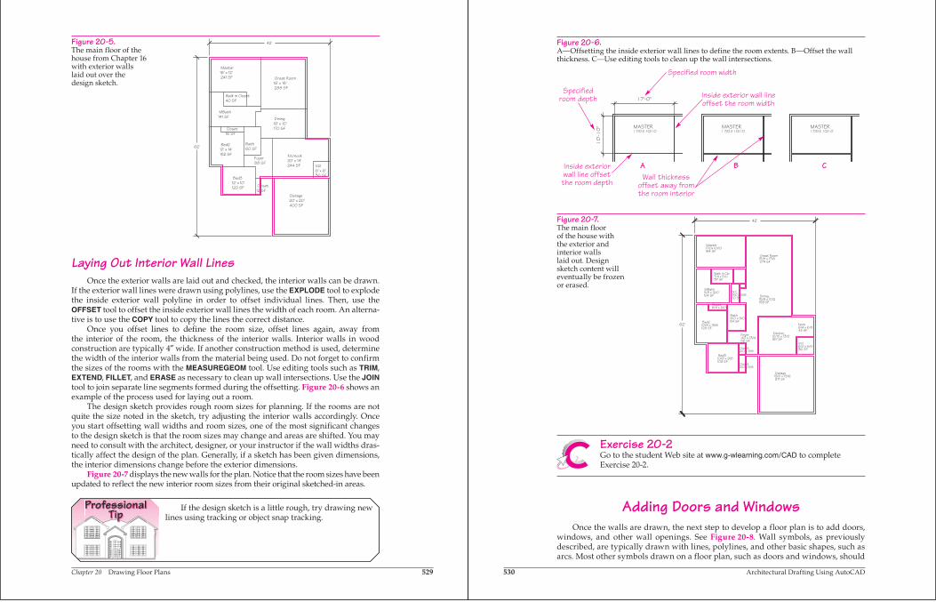
Figure 20-5.The main floor of the house from Chapter 16 with exterior walls laid out over the design sketch.
Foyer88 SF
MBath141 SF
Bath60 SF
Util6' x 6'36 SF
Kit/nook20' x 14'244 SF
Garage20' x 20'400 SF
Bed312' x 10'120 SF
Bed212' x 14'152 SF
Dining16' x 10'170 SF
Great Room16' x 18'288 SF
Master18' x 12'241 SF
62'
42'
Walk in Closet40 SF
Closet16 SF
Closet12 SF
530 Architectural Drafting Using AutoCAD
Figure 20-7.The main floor of the house with the exterior and interior walls laid out. Design sketch content will eventually be frozen or erased.
62'
42'
MBath11/8 x 12/0104 SF
Bath6/0 x 9/054 SF
Foyer4/2 x 13/456 SF
Util6/0 x 6/036 SF
Kitchen12/10 x 13/0167 SF
Garage19/0 x 19/6371 SF
Bed310/8 x 9/8103 SF
Bed210/8 x 13/6128 SF
Dining15/8 x 10/2159 SF
Great Room15/8 x 17/6274 SF
Master17/0x 10/10184 SF
Walk in Clo7/4 x 5/037 SF
Closet6/4 x 2/0
Closet2/0 x 5/8
W.C.3/0 x 6/820 SF
Closet2/0 x 3/8
Nook6/4 x 6/842 SF
Figure 20-6.A—Offsetting the inside exterior wall lines to define the room extents. B—Offset the wall thickness. C—Use editing tools to clean up the wall intersections.
A B C
Specified room width
Specifiedroom depth
Inside exteriorwall line offsetthe room depth
Inside exterior wall lineoffset the room width
Wall thicknessoffset away fromthe room interior
Exercise 20-2Go to the student Web site at www.g-wlearning.com/CAD to complete Exercise 20-2.
Adding Doors and WindowsOnce the walls are drawn, the next step to develop a floor plan is to add doors,
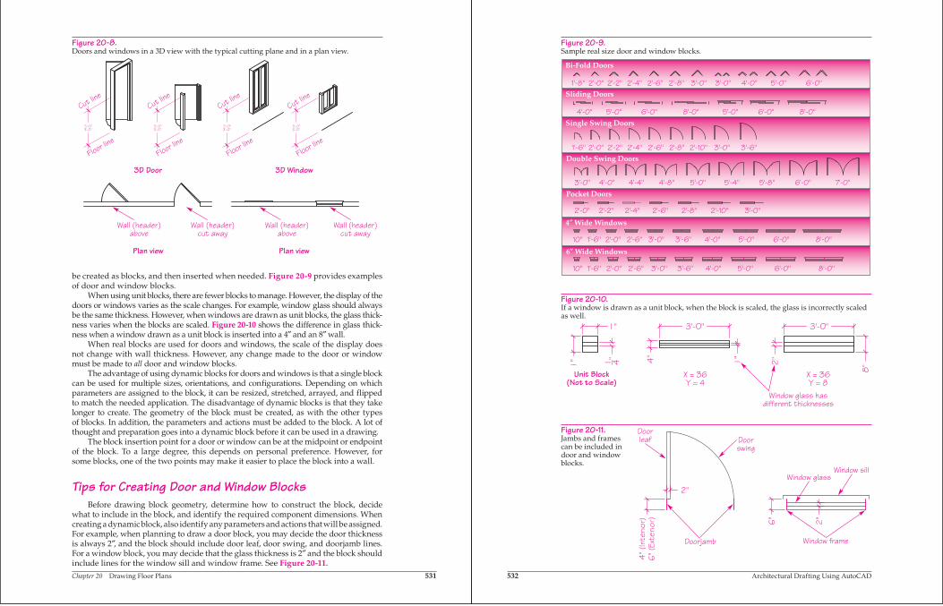
windows, and other wall openings. See Figure 20-8. Wall symbols, as previously described, are typically drawn with lines, polylines, and other basic shapes, such as arcs. Most other symbols drawn on a floor plan, such as doors and windows, should
Chapter 20 Drawing Floor Plans 531
be created as blocks, and then inserted when needed. Figure 20-9 provides examples of door and window blocks.
When using unit blocks, there are fewer blocks to manage. However, the display of the doors or windows varies as the scale changes. For example, window glass should always be the same thickness. However, when windows are drawn as unit blocks, the glass thick-ness varies when the blocks are scaled. Figure 20-10 shows the difference in glass thick-ness when a window drawn as a unit block is inserted into a 4″ and an 8″ wall.
When real blocks are used for doors and windows, the scale of the display does not change with wall thickness. However, any change made to the door or window must be made to all door and window blocks.
The advantage of using dynamic blocks for doors and windows is that a single block can be used for multiple sizes, orientations, and configurations. Depending on which parameters are assigned to the block, it can be resized, stretched, arrayed, and flipped to match the needed application. The disadvantage of dynamic blocks is that they take longer to create. The geometry of the block must be created, as with the other types of blocks. In addition, the parameters and actions must be added to the block. A lot of thought and preparation goes into a dynamic block before it can be used in a drawing.
The block insertion point for a door or window can be at the midpoint or endpoint of the block. To a large degree, this depends on personal preference. However, for some blocks, one of the two points may make it easier to place the block into a wall.
Tips for Creating Door and Window BlocksBefore drawing block geometry, determine how to construct the block, decide
what to include in the block, and identify the required component dimensions. When creating a dynamic block, also identify any parameters and actions that will be assigned. For example, when planning to draw a door block, you may decide the door thickness is always 2″, and the block should include door leaf, door swing, and doorjamb lines. For a window block, you may decide that the glass thickness is 2″ and the block should include lines for the window sill and window frame. See Figure 20-11.
Figure 20-8.Doors and windows in a 3D view with the typical cutting plane and in a plan view.
Cut line
Floor line
Cut line
Floor line
Cut line
Floor line
Cut line
Floor line
3D Door 3D Window
Plan view Plan view
Wall (header)above
Wall (header)cut away
Wall (header)above
Wall (header)cut away
532 Architectural Drafting Using AutoCAD
Figure 20-10.If a window is drawn as a unit block, when the block is scaled, the glass is incorrectly scaled as well.
Unit Block(Not to Scale)
X = 36Y = 4
X = 36Y = 8
Window glass hasdifferent thicknesses
Figure 20-11.Jambs and frames can be included in door and window blocks.
Doorleaf Door
swing
Window glass
Window frame
Window sill
Doorjamb
Figure 20-9.Sample real size door and window blocks.
6″ Wide Windows
4″ Wide Windows
Pocket Doors
Double Swing Doors
Single Swing Doors
Sliding Doors
Bi-Fold Doors
4'-0"3'-0"1'-8" 2'-0" 5'-0"2'-4"2'-2" 2'-6" 6'-0"3'-0"2'-8"
10" 1'-6" 2'-6"2'-0" 5'-0"3'-0" 3'-6" 4'-0" 6'-0" 8'-0"
8'-0"5'-0" 6'-0"5'-0"4'-0" 6'-0" 8'-0"
2'-2"2'-0" 2'-4" 2'-6" 2'-8" 2'-10" 3'-0"
2'-8"2'-2"1'-6" 2'-0" 2'-4" 2'-6" 2'-10" 3'-0" 3'-6"
4'-0"3'-0" 4'-4" 4'-8" 5'-0" 5'-4" 5'-8" 6'-0" 7'-0"
3'-0"10" 1'-6" 2'-6"2'-0" 3'-6" 4'-0" 5'-0" 6'-0" 8'-0"
Chapter 20 Drawing Floor Plans 533
Block geometry should be drawn on the 0 layer using the ByLayer setting for the color, linetype, and lineweight. In this way, the block takes on the properties of the layer on which it is inserted. As an option, try using a ByBlock color and linetype for the doorjambs and window frame. Use the ByLayer color setting for the rest of the block geometry. Then, before the block is inserted, set the current color to the same color as the wall layer. When the block is inserted on the door or window layer, the door or window geometry takes on the layer color, but the jambs or frame lines take on the current color, which matches the wall layer. See Figure 20-12.
After drawing the geometry, create the block. When selecting the insertion point, pick a location that is logical, such as the hinge of the door or the frame end of a window. After the block definition is saved, open the Block Editor if creating a dynamic block. Assign parameters and actions as needed. After saving the dynamic block, test it to ensure the parameters and actions work correctly.
ProfessionalTip
Door and window blocks are well suited to be created as dynamic blocks. Linear, alignment, flip, and visibility parameters and applicable actions allow for much flexibility for door and window blocks. Other parameters and actions may also be useful in door and window blocks.
Inserting Door and Window BlocksBefore inserting doors and windows, create appropriate layers, such as Doors or
A-DOOR for doors, and Windows or A-GLAZ for windows. Next, if the blocks have the ByBlock color setting for the doorjambs and window frames, set the current color to the same color as the walls. Then, use the INSERT tool, DesignCenter, or the Tool Paletteswindow to insert the blocks. Be sure to set the correct layer current before inserting the blocks.
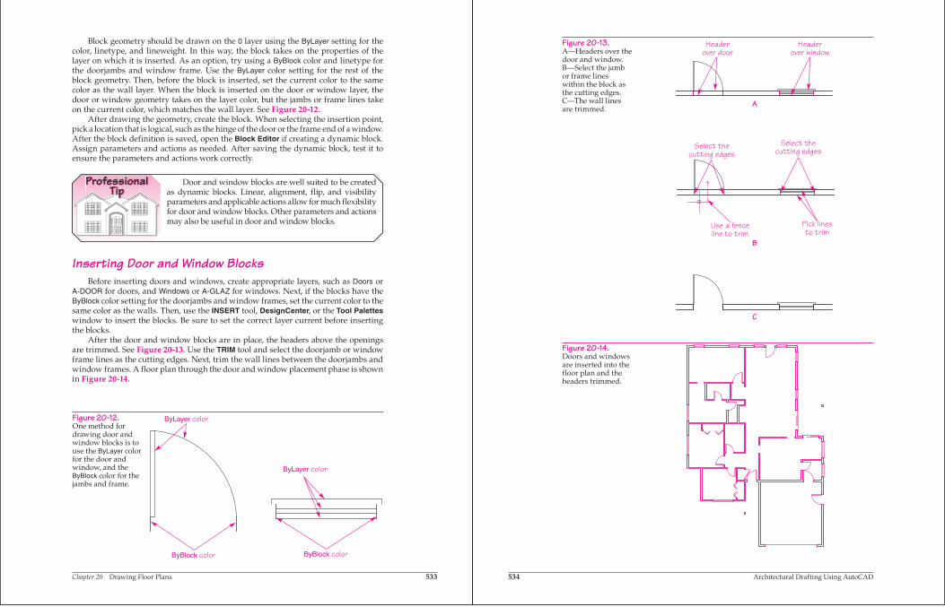
After the door and window blocks are in place, the headers above the openings are trimmed. See Figure 20-13. Use the TRIM tool and select the doorjamb or window frame lines as the cutting edges. Next, trim the wall lines between the doorjambs and window frames. A floor plan through the door and window placement phase is shown in Figure 20-14.
Figure 20-12.One method for drawing door and window blocks is to use the ByLayer color for the door and window, and the ByBlock color for the jambs and frame.
ByLayer color
ByLayer color
ByBlock color ByBlock color
534 Architectural Drafting Using AutoCAD
Figure 20-13.A—Headers over the door and window. B—Select the jamb or frame lines within the block as the cutting edges. C—The wall lines are trimmed.
Headerover door
Headerover window
Select thecutting edges
Select thecutting edges
Use a fenceline to trim
A
B
C
Pick linesto trim
Figure 20-14.Doors and windows are inserted into the floor plan and the headers trimmed.
Chapter 20 Drawing Floor Plans 535
ProfessionalTip
Use drawing aids such as object snaps, tracking, and AutoTrack when inserting doors and windows. When prompted for the insertion point of the block, track a distance from a corner of the walls to where the opening is to be placed.
Exercise 20-3Go to the student Web site at www.g-wlearning.com/CAD to complete Exercise 20-3.
Adding Stairs and Confirming the LayoutDepending on the design of the building, stairs may be required to provide access
to a different level of the building. See Figure 20-15. Stairs are made up of risers and treads. Stairs are designed to conform to local building codes regarding staircase widths, maximum riser heights, and minimum tread depths. Stair layout is used to confirm the placement of adjoining walls.
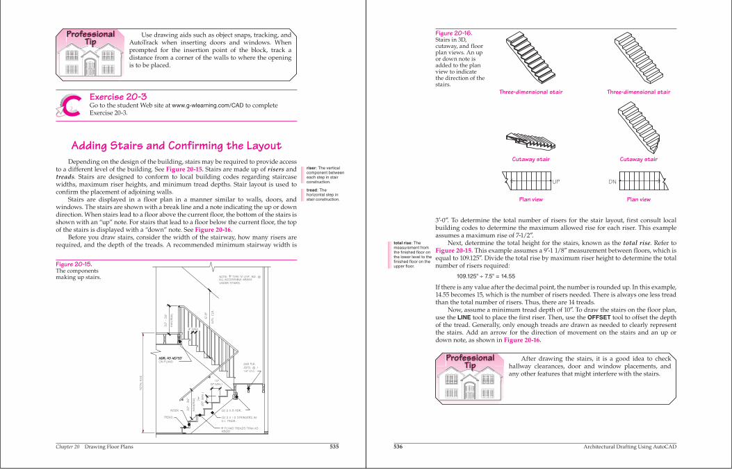
Stairs are displayed in a floor plan in a manner similar to walls, doors, and windows. The stairs are shown with a break line and a note indicating the up or down direction. When stairs lead to a floor above the current floor, the bottom of the stairs is shown with an “up” note. For stairs that lead to a floor below the current floor, the top of the stairs is displayed with a “down” note. See Figure 20-16.
Before you draw stairs, consider the width of the stairway, how many risers are required, and the depth of the treads. A recommended minimum stairway width is
Figure 20-15.The components making up stairs.
riser: The vertical component between each step in stair construction.
tread: The horizontal step in stair construction.
536 Architectural Drafting Using AutoCAD
3′-0″. To determine the total number of risers for the stair layout, first consult local building codes to determine the maximum allowed rise for each riser. This example assumes a maximum rise of 7-1/2″.
Next, determine the total height for the stairs, known as the total rise. Refer to Figure 20-15. This example assumes a 9′-1 1/8″ measurement between floors, which is equal to 109.125″. Divide the total rise by maximum riser height to determine the total number of risers required:
109.125" ÷ 7.5" = 14.55
If there is any value after the decimal point, the number is rounded up. In this example, 14.55 becomes 15, which is the number of risers needed. There is always one less tread than the total number of risers. Thus, there are 14 treads.
Now, assume a minimum tread depth of 10″. To draw the stairs on the floor plan, use the LINE tool to place the first riser. Then, use the OFFSET tool to offset the depth of the tread. Generally, only enough treads are drawn as needed to clearly represent the stairs. Add an arrow for the direction of movement on the stairs and an up or down note, as shown in Figure 20-16.
ProfessionalTip
After drawing the stairs, it is a good idea to check hallway clearances, door and window placements, and any other features that might interfere with the stairs.
Figure 20-16.Stairs in 3D, cutaway, and floor plan views. An up or down note is added to the plan view to indicate the direction of the stairs.
Three-dimensional stair
Plan view Plan view
Three-dimensional stair
Cutaway stair Cutaway stair
total rise: The measurement from the finished floor on the lower level to the finished floor on the upper floor.
Chapter 20 Drawing Floor Plans 537
Exercise 20-4Go to the student Web site at www.g-wlearning.com/CAD to complete Exercise 20-4.
Drawing FireplacesA fireplace is used for heating, cooking, and warmth, and for decorative purposes.
The space where the fire is contained is called a firebox. A chimney or flue allows gas and exhaust to escape the building. Fireplaces are typically constructed in building interiors. Outdoor fireplaces can also be designed, and can include a grill.
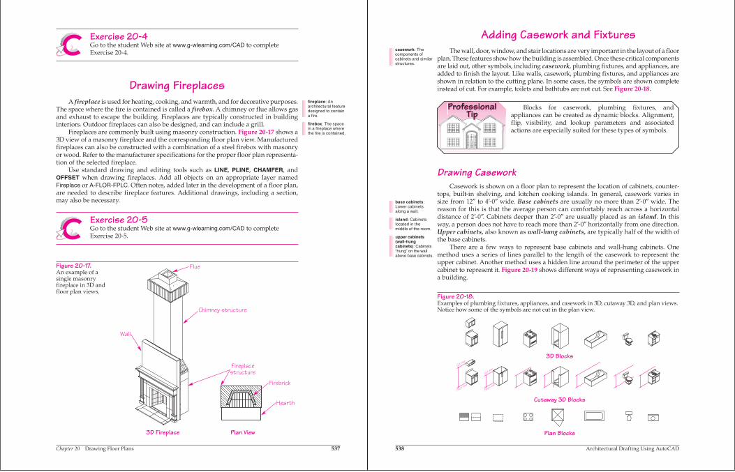
Fireplaces are commonly built using masonry construction. Figure 20-17 shows a 3D view of a masonry fireplace and the corresponding floor plan view. Manufactured fireplaces can also be constructed with a combination of a steel firebox with masonry or wood. Refer to the manufacturer specifications for the proper floor plan representa-tion of the selected fireplace.
Use standard drawing and editing tools such as LINE, PLINE, CHAMFER, and OFFSET when drawing fireplaces. Add all objects on an appropriate layer named Fireplace or A-FLOR-FPLC. Often notes, added later in the development of a floor plan, are needed to describe fireplace features. Additional drawings, including a section, may also be necessary.
Exercise 20-5Go to the student Web site at www.g-wlearning.com/CAD to complete Exercise 20-5.
Figure 20-17.An example of a single masonry fireplace in 3D and floor plan views.
Plan View3D Fireplace
Wall
Chimney structure
Flue
Hearth
Fireplacestructure
Firebrick
fireplace: An architectural feature designed to contain a fire.
firebox: The space in a fireplace where the fire is contained.
538 Architectural Drafting Using AutoCAD
Adding Casework and FixturesThe wall, door, window, and stair locations are very important in the layout of a floor
plan. These features show how the building is assembled. Once these critical components are laid out, other symbols, including casework, plumbing fixtures, and appliances, are added to finish the layout. Like walls, casework, plumbing fixtures, and appliances are shown in relation to the cutting plane. In some cases, the symbols are shown complete instead of cut. For example, toilets and bathtubs are not cut. See Figure 20-18.
ProfessionalTip
Blocks for casework, plumbing fixtures, and appliances can be created as dynamic blocks. Alignment, flip, visibility, and lookup parameters and associated actions are especially suited for these types of symbols.
Drawing CaseworkCasework is shown on a floor plan to represent the location of cabinets, counter-
tops, built-in shelving, and kitchen cooking islands. In general, casework varies in size from 12″ to 4′-0″ wide. Base cabinets are usually no more than 2′-0″ wide. The reason for this is that the average person can comfortably reach across a horizontal distance of 2′-0″. Cabinets deeper than 2′-0″ are usually placed as an island. In this way, a person does not have to reach more than 2′-0″ horizontally from one direction. Upper cabinets, also known as wall-hung cabinets, are typically half of the width of the base cabinets.
There are a few ways to represent base cabinets and wall-hung cabinets. One method uses a series of lines parallel to the length of the casework to represent the upper cabinet. Another method uses a hidden line around the perimeter of the upper cabinet to represent it. Figure 20-19 shows different ways of representing casework in a building.
casework: The components of cabinets and similar structures.
Figure 20-18.Examples of plumbing fixtures, appliances, and casework in 3D, cutaway 3D, and plan views. Notice how some of the symbols are not cut in the plan view.
3D Blocks
Cutaway 3D Blocks
Plan Blocks
base cabinets:Lower cabinets along a wall.
island: Cabinets located in the middle of the room.
upper cabinets (wall-hung cabinets): Cabinets “hung” on the wall above base cabinets.
Chapter 20 Drawing Floor Plans 539
Adding Plumbing FixturesPlumbing fixtures are drawn as symbols and placed in the drawing to represent
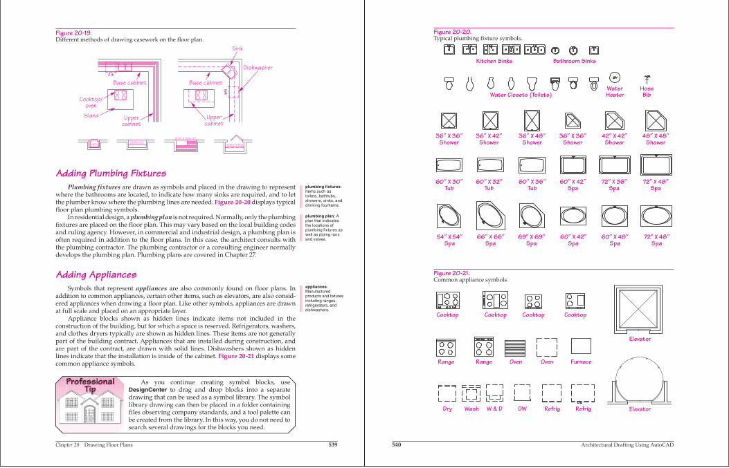
where the bathrooms are located, to indicate how many sinks are required, and to let the plumber know where the plumbing lines are needed. Figure 20-20 displays typical floor plan plumbing symbols.
In residential design, a plumbing plan is not required. Normally, only the plumbing fixtures are placed on the floor plan. This may vary based on the local building codes and ruling agency. However, in commercial and industrial design, a plumbing plan is often required in addition to the floor plans. In this case, the architect consults with the plumbing contractor. The plumbing contractor or a consulting engineer normally develops the plumbing plan. Plumbing plans are covered in Chapter 27.
Adding AppliancesSymbols that represent appliances are also commonly found on floor plans. In
addition to common appliances, certain other items, such as elevators, are also consid-ered appliances when drawing a floor plan. Like other symbols, appliances are drawn at full scale and placed on an appropriate layer.
Appliance blocks shown as hidden lines indicate items not included in the construction of the building, but for which a space is reserved. Refrigerators, washers, and clothes dryers typically are shown as hidden lines. These items are not generally part of the building contract. Appliances that are installed during construction, and are part of the contract, are drawn with solid lines. Dishwashers shown as hidden lines indicate that the installation is inside of the cabinet. Figure 20-21 displays some common appliance symbols.
ProfessionalTip
As you continue creating symbol blocks, use DesignCenter to drag and drop blocks into a separate drawing that can be used as a symbol library. The symbol library drawing can then be placed in a folder containing files observing company standards, and a tool palette can be created from the library. In this way, you do not need to search several drawings for the blocks you need.
Figure 20-19.Different methods of drawing casework on the floor plan.
Dishwasher
Sink
Base cabinet Base cabinet
Cooktop/oven
Island Uppercabinet
Uppercabinet
LINENBOOKCASE
DESK & SHELVES
SHELF & ROD
plumbing fixtures:Items such as toilets, bathtubs, showers, sinks, and drinking fountains.
plumbing plan: A plan that indicates the locations of plumbing fixtures as well as piping runs and valves.
appliances:Manufactured products and fixtures including ranges, refrigerators, and dishwashers.
540 Architectural Drafting Using AutoCAD
Figure 20-20.Typical plumbing fixture symbols.
Kitchen Sinks Bathroom Sinks
Water Closets (Toilets)WaterHeater
HoseBib
36″ X 36″Shower
36″ X 42″Shower
36″ X 48″Shower
36″ X 36″Shower
60″ X 30″Tub
60″ X 32″Tub
60″ X 36″Tub
60″ X 42″Spa
72″ X 36″Spa
72″ X 48″Spa
42″ X 42″Shower
48″ X 48″Shower
54″ X 54″Spa
66″ X 66″Spa
69″ X 69″Spa
60″ X 42″Spa
60″ X 48″Spa
72″ X 48″Spa
Figure 20-21.Common appliance symbols.
Cooktop Cooktop Cooktop Cooktop
Dry Wash W & D DW Refrig Refrig
Elevator
Elevator
Range Range Oven Oven Furnace
Chapter 20 Drawing Floor Plans 541
Exercise 20-6Go to the student Web site at www.g-wlearning.com/CAD to complete Exercise 20-6.
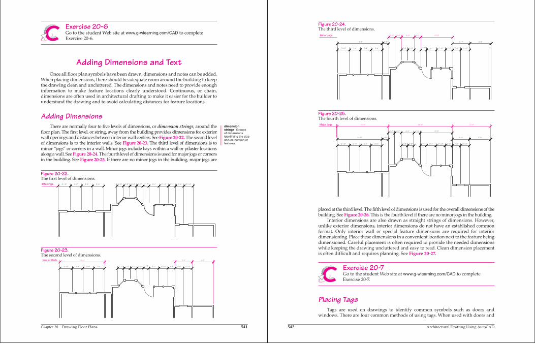
Adding Dimensions and TextOnce all floor plan symbols have been drawn, dimensions and notes can be added.
When placing dimensions, there should be adequate room around the building to keep the drawing clean and uncluttered. The dimensions and notes need to provide enough information to make feature locations clearly understood. Continuous, or chain, dimensions are often used in architectural drafting to make it easier for the builder to understand the drawing and to avoid calculating distances for feature locations.
Adding DimensionsThere are normally four to five levels of dimensions, or dimension strings, around the
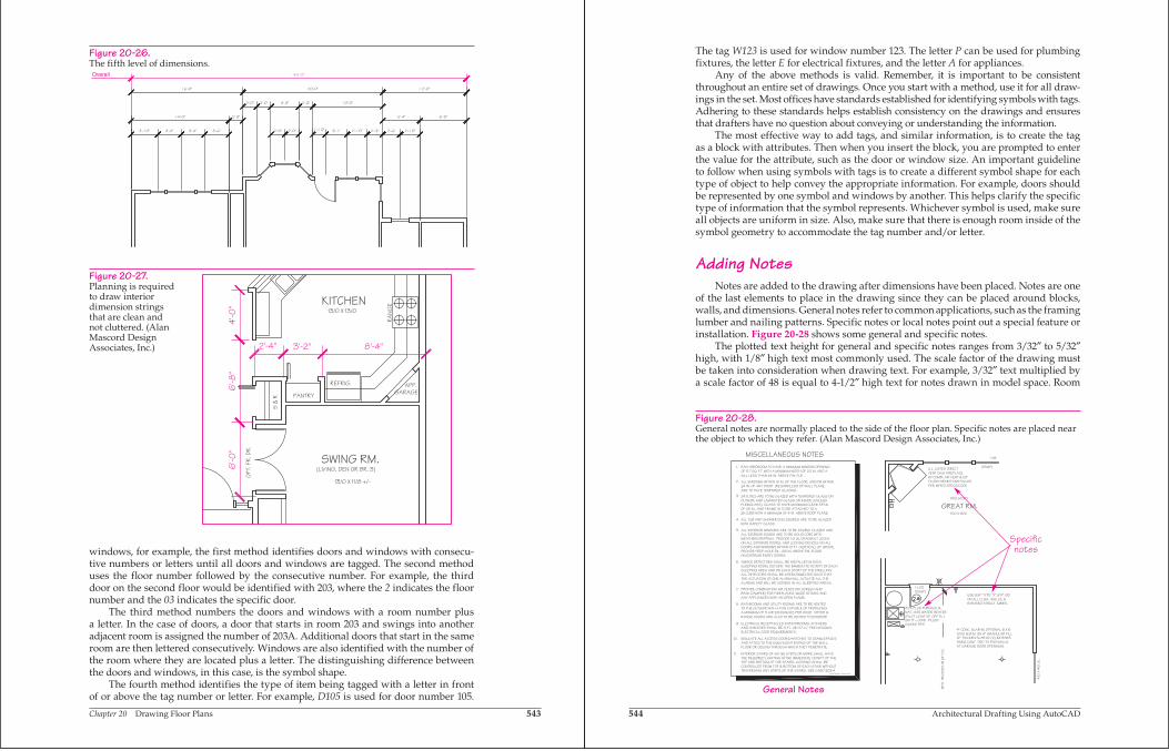
floor plan. The first level, or string, away from the building provides dimensions for exterior wall openings and distances between interior wall centers. See Figure 20-22. The second level of dimensions is to the interior walls. See Figure 20-23. The third level of dimensions is to minor “jogs” or corners in a wall. Minor jogs include bays within a wall or pilaster locations along a wall. See Figure 20-24. The fourth level of dimensions is used for major jogs or corners in the building. See Figure 20-25. If there are no minor jogs in the building, major jogs are
dimension strings: Groups of dimensions identifying the size and/or location of features.
Figure 20-22.The first level of dimensions.
Figure 20-23.The second level of dimensions.
Interior Walls
542 Architectural Drafting Using AutoCAD
placed at the third level. The fifth level of dimensions is used for the overall dimensions of the building. See Figure 20-26. This is the fourth level if there are no minor jogs in the building.
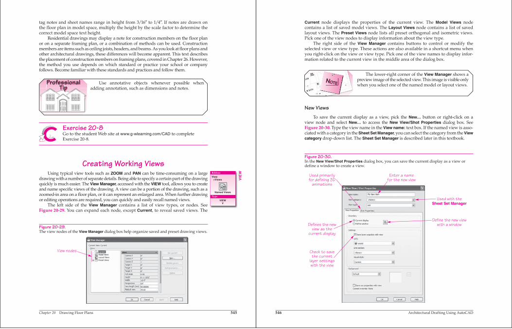
Interior dimensions are also drawn as straight strings of dimensions. However, unlike exterior dimensions, interior dimensions do not have an established common format. Only interior wall or special feature dimensions are required for interior dimensioning. Place these dimensions in a convenient location next to the feature being dimensioned. Careful placement is often required to provide the needed dimensions while keeping the drawing uncluttered and easy to read. Clean dimension placement is often difficult and requires planning. See Figure 20-27.
Exercise 20-7Go to the student Web site at www.g-wlearning.com/CAD to complete Exercise 20-7.
Placing TagsTags are used on drawings to identify common symbols such as doors and
windows. There are four common methods of using tags. When used with doors and
Figure 20-25.The fourth level of dimensions.Major Jogs
Figure 20-24.The third level of dimensions.
Minor Jogs
Chapter 20 Drawing Floor Plans 543
windows, for example, the first method identifies doors and windows with consecu-tive numbers or letters until all doors and windows are tagged. The second method uses the floor number followed by the consecutive number. For example, the third door on the second floor would be identified with 203, where the 2 indicates the floor number and the 03 indicates the specific door.
The third method numbers the doors and windows with a room number plus a letter. In the case of doors, a door that starts in room 203 and swings into another adjacent room is assigned the number of 203A. Additional doors that start in the same room are then lettered consecutively. Windows are also identified with the number of the room where they are located plus a letter. The distinguishing difference between the doors and windows, in this case, is the symbol shape.
The fourth method identifies the type of item being tagged with a letter in front of or above the tag number or letter. For example, D105 is used for door number 105.
Figure 20-26.The fifth level of dimensions.Overall
Figure 20-27.Planning is required to draw interior dimension strings that are clean and not cluttered. (Alan Mascord Design Associates, Inc.)
SWING RM.
13/0 X 13/0
13/0 X 11/8 +/-
REFRIG.
PANTRY
APP.GARAGE
OPT.
FR.
DR.
(LIVING, DEN OR BR. 3)
S &
R
KITCHEN
RANG
E
2'-4" 3'-2" 8'-4"
4'-0
"6
'-8"
6'-0
"
544 Architectural Drafting Using AutoCAD
The tag W123 is used for window number 123. The letter P can be used for plumbing fixtures, the letter E for electrical fixtures, and the letter A for appliances.
Any of the above methods is valid. Remember, it is important to be consistent throughout an entire set of drawings. Once you start with a method, use it for all draw-ings in the set. Most offices have standards established for identifying symbols with tags. Adhering to these standards helps establish consistency on the drawings and ensures that drafters have no question about conveying or understanding the information.
The most effective way to add tags, and similar information, is to create the tag as a block with attributes. Then when you insert the block, you are prompted to enter the value for the attribute, such as the door or window size. An important guideline to follow when using symbols with tags is to create a different symbol shape for each type of object to help convey the appropriate information. For example, doors should be represented by one symbol and windows by another. This helps clarify the specific type of information that the symbol represents. Whichever symbol is used, make sure all objects are uniform in size. Also, make sure that there is enough room inside of the symbol geometry to accommodate the tag number and/or letter.
Adding NotesNotes are added to the drawing after dimensions have been placed. Notes are one
of the last elements to place in the drawing since they can be placed around blocks, walls, and dimensions. General notes refer to common applications, such as the framing lumber and nailing patterns. Specific notes or local notes point out a special feature or installation. Figure 20-28 shows some general and specific notes.
The plotted text height for general and specific notes ranges from 3/32″ to 5/32″high, with 1/8″ high text most commonly used. The scale factor of the drawing must be taken into consideration when drawing text. For example, 3/32″ text multiplied by a scale factor of 48 is equal to 4-1/2″ high text for notes drawn in model space. Room
Figure 20-28.General notes are normally placed to the side of the floor plan. Specific notes are placed near the object to which they refer. (Alan Mascord Design Associates, Inc.)
H.B.
(TEMP)
PER MFR'S SPECS/CODEFLUSH HEARTH INSTALLEDW/ COMB. AIR VENT & 20"VENT GAS FIREPLACEU.L. LISTED DIRECT
17/0 X 13/0
TWO STORY
GREAT RM.
MFD
. TRU
SS
ES @
24"
O.C
.
4/0
X 4
/0 S
L.
USE 5/8" TYPE "X" GYP. BD.ON ALL CLGS., WALLS, &EXPOSED STRUCT. MBRS.
10/10 W.W.M. ON 4" GRANULAR FILL.4" CONC. SLAB W/ OPTIONAL 6 X 6
12" THICKEN SLAB W/ (2) #4 BARSHORIZ CONT. TIED TO FND WALLSAT GARAGE DOOR OPENINGS.
(PILOT LIGHT 18" OFF FL.)NAT. GAS WATER HEATER80% PLUS FURNACE &
(W/ 3"~ CONC. FILLEDGUARD PIPE
(TEMP)1-LITE
INTERIOR STAIRS OF SIX (6) STEPS OR MORE SHALL HAVETHE REQUIRED LIGHTING IN THE IMMEDIATE VICINITY OF THETOP AND BOTTOM OF THE STAIRS. LIGHTING SHALL BECONTROLLED FROM TOP & BOTTOM OF EACH STAIR WITHOUTTRAVERSING ANY STEPS OF THE STAIRS. SEE CABO 303.4
11.
MISCELLANEOUS NOTES1. EACH BEDROOM TO HAVE A MINIMUM WINDOW OPENING
OF 5.7 SQ. FT. WITH A MINIMUM WIDTH OF 20 IN. AND ASILL LESS THAN 44 IN. ABOVE FIN. FLR.
ALL WINDOWS WITHIN 18 IN. OF THE FLOOR, AND/OR WITHIN24 IN. OF ANY DOOR (REGARDLESS OF WALL PLANE,
SKYLITES ARE TO BE GLAZED WITH TEMPERED GLASS ONOUTSIDE AND LAMINATED GLASS ON INSIDE (UNLESSPLEXIGLASS). GLASS TO HAVE MAXIMUM CLEAR SPANOF 25 IN., AND FRAME IS TO BE ATTACHED TO A2X CURB WITH A MINIMUM OF 4 IN. ABOVE ROOF PLANE.
ALL TUB AND SHOWER ENCLOSURES ARE TO BE GLAZEDWITH SAFETY GLASS.
ALL EXTERIOR WINDOWS ARE TO BE DOUBLE GLAZED ANDALL EXTERIOR DOORS ARE TO BE SOLID CORE WITH WEATHERSTRIPPING. PROVIDE 1/2 IN. DEADBOLT LOCKSON ALL EXTERIOR DOORS, AND LOCKING DEVICES ON ALLDOORS AND WINDOWS WITHIN 10 FT. (VERTICAL) OF GRADE.PROVIDE PEEP-HOLE 54 - 66 IN. ABOVE FIN. FLOORON EXTERIOR ENTRY DOORS.
PROVIDE COMBUSTION AIR VENTS (W/ SCREEN ANDBACK DAMPER) FOR FIREPLACES, WOOD STOVES ANDANY APPLIANCES WITH AN OPEN FLAME.
BATHROOMS AND UTILITY ROOMS ARE TO BE VENTEDTO THE OUTSIDE WITH A FAN CAPABLE OF PRODUCINGA MINIMUM OF 5 AIR EXCHANGES PER HOUR. DRYER &
2.
3.
4.
5.
6.
7.
8.
RANGE HOODS ARE ALSO TO BE VENTED TO EXTERIOR.
9. ELECTRICAL RECEPTACLES IN BATHROOMS, KITCHENSAND GARAGES SHALL BE G.F.I. OR G.F.I.C. PER NATIONALELECTRICAL CODE REQUIREMENTS.
ARE TO HAVE TEMPERED GLAZING.
M-NOTE2 REV. 8/19/xx MCD
10. INSULATE ALL ACCESS DOORS/HATCHES TO CRAWLSPACESAND ATTICS TO THE EQUIVALENT RATING OF THE WALL,FLOOR OR CEILING THROUGH WHICH THEY PENETRATE.
SMOKE DETECTORS SHALL BE INSTALLED IN EACHSLEEPING ROOM, OUTSIDE THE IMMEDIATE VICINITY OF EACHSLEEPING AREA AND ON EACH STORY OF THE DWELLING.ALL DETECTORS SHALL BE INTERCONNECTED SUCH THATTHE ACTUATION OF ONE ALARM WILL ACTUATE ALL THEALARMS AND WILL BE AUDIBLE IN ALL SLEEPING AREAS.
Specificnotes
General Notes
Chapter 20 Drawing Floor Plans 545
tag notes and sheet names range in height from 3/16″ to 1/4″. If notes are drawn on the floor plan in model space, multiply the height by the scale factor to determine the correct model space text height.
Residential drawings may display a note for construction members on the floor plan or on a separate framing plan, or a combination of methods can be used. Construction members are items such as ceiling joists, headers, and beams. As you look at floor plans and other architectural drawings, these differences will become apparent. This text describes the placement of construction members on framing plans, covered in Chapter 26. However, the method you use depends on which standard or practice your school or company follows. Become familiar with these standards and practices and follow them.
ProfessionalTip
Use annotative objects whenever possible when adding annotation, such as dimensions and notes.
Exercise 20-8Go to the student Web site at www.g-wlearning.com/CAD to complete Exercise 20-8.
Creating Working ViewsUsing typical view tools such as ZOOM and PAN can be time-consuming on a large
drawing with a number of separate details. Being able to specify a certain part of the drawing quickly is much easier. The View Manager, accessed with the VIEW tool, allows you to create and name specific views of the drawing. A view can be a portion of the drawing, such as a zoomed-in area on a floor plan, or it can represent an enlarged area. When further drawing or editing operations are required, you can quickly and easily recall named views.
The left side of the View Manager contains a list of view types, or nodes. See Figure 20-29. You can expand each node, except Current, to reveal saved views. The
Figure 20-29.The view nodes of the View Manager dialog box help organize saved and preset drawing views.
View nodes
Ribbon
View>Views
Named Views
Type
VIEWV
VIE
W
546 Architectural Drafting Using AutoCAD
Current node displays the properties of the current view. The Model Views node contains a list of saved model views. The Layout Views node contains a list of saved layout views. The Preset Views node lists all preset orthogonal and isometric views. Pick one of the view nodes to display information about the view type.
The right side of the View Manager contains buttons to control or modify the selected view or view type. These actions are also available in a shortcut menu when you right-click on the view or view type. Pick one of the view names to display infor-mation related to the current view in the middle area of the dialog box.
LLIINN..
MMEE DD..
CC AABB ..
2222""xx3300""
AATTTT IICC
AACC CC EE SS SS
77
88
99
2
BB
HHBB
99
CC LLOOSS
MM BB AATTHH
NOTE
The lower-right corner of the View Manager shows a preview image of the selected view. This image is visible only when you select one of the named model or layout views.
New ViewsTo save the current display as a view, pick the New… button or right-click on a
view node and select New… to access the New View/Shot Properties dialog box. See Figure 20-30. Type the view name in the View name: text box. If the named view is asso-ciated with a category in the Sheet Set Manager, you can select the category from the View category drop-down list. The Sheet Set Manager is described later in this textbook.
Figure 20-30.In the New View/Shot Properties dialog box, you can save the current display as a view or define a window to create a view.
Used primarily for defining 3D
animations
Defines the new view as the
current display
Check to save the current
layer settings with the view
Enter a name for the new view
Used with theSheet Set Manager
Define the new view with a window
Chapter 20 Drawing Floor Plans 547
The New View/Shot Properties dialog box provides many options that are appli-cable to 3D modeling animations. To create a basic 2D view, select Still from the View type drop-down list, and use the options in the View Properties tab. The Current displayradio button is the default. Pick OK to add the view name to the list. AutoCAD creates a view from the current display.
To use a window to define the view, pick the Define window radio button in the New View/Shot Properties dialog box, and then pick the Define view window button. Pick two points to define a window. After you select the second corner, the New View/Shot Properties dialog box reappears. When you pick the OK button, the View Managerupdates to reflect the new view.
Select the Save layer snapshot with view check box to save the current layer settings when you save a new view. Saved layer settings are recalled each time the view is set current.
Activating ViewsTo display one of the listed views from inside the View Manager, pick the view name
from the list in the Views area and pick the Set Current button. The name of the current view appears in the Current View: label above the Views area. Pick the OK button to display the selected view. To display a view without accessing the View Manager, select the name of the view from the list in the Views panel of the View ribbon tab.
LLIINN..
MMEE DD..
CC AABB ..
2222""xx3300""
AATTTT IICC
AACC CC EE SS SS
77
88
99
2
BB
HHBB
99
CC LLOOSS
MM BB AATTHH
NOTE
The Preset Views node allows you to choose one of the 10 preset orthogonal or isometric views. Orthogonal and isometric views are more commonly used in conjunction with 3D drawings.
ProfessionalTip
Part of your project planning should include view names. A consistent naming system guarantees that all users know the view names without having to list them. The views can be set as part of the template drawings.
Exercise 20-9Go to the student Web site at www.g-wlearning.com/CAD to complete Exercise 20-9.
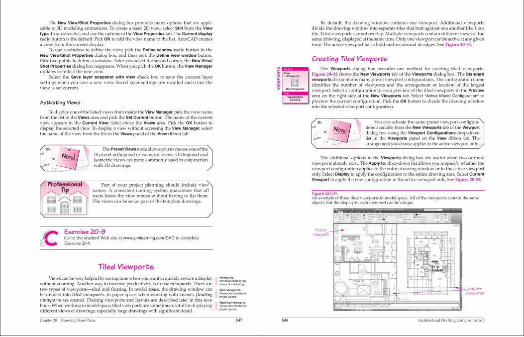
Tiled ViewportsViews can be very helpful by saving time when you want to quickly restore a display
without zooming. Another way to increase productivity is to use viewports. There are two types of viewports—tiled and floating. In model space, the drawing window can be divided into tiled viewports. In paper space, when working with layouts, floating viewports are created. Floating viewports and layouts are described later in this text-book. When working in model space, tiled viewports are sometimes useful for displaying different views of drawings, especially large drawings with significant detail.
viewports:Windows displaying views of a drawing.
tiled viewports:Viewports created in model space.
floating viewports:Viewports created in paper space.
548 Architectural Drafting Using AutoCAD
By default, the drawing window contains one viewport. Additional viewports divide the drawing window into separate tiles that butt against one another like floor tile. Tiled viewports cannot overlap. Multiple viewports contain different views of the same drawing, displayed at the same time. Only one viewport can be active at any given time. The active viewport has a bold outline around its edges. See Figure 20-31.
Creating Tiled ViewportsThe Viewports dialog box provides one method for creating tiled viewports.
Figure 20-32 shows the New Viewports tab of the Viewports dialog box. The Standard viewports: list contains many preset viewport configurations. The configuration name identifies the number of viewports and the arrangement or location of the largest viewport. Select a configuration to see a preview of the tiled viewports in the Previewarea on the right side of the New Viewports tab. Select Active Model Configuration to preview the current configuration. Pick the OK button to divide the drawing window into the selected viewport configuration.
LLIINN..
MMEE DD..
CC AABB ..
2222""xx3300""
AATTTT IICC
AACC CC EE SS SS
77
88
99
2
BB
HHBB
99
CC LLOOSS
MM BB AATTHH
NOTE
You can activate the same preset viewport configura-tions available from the New Viewports tab of the Viewportdialog box using the Viewport Configurations drop-down list in the Viewports panel on the View ribbon tab. The arrangement you choose applies to the active viewport only.
The additional options in the Viewports dialog box are useful when two or more viewports already exist. The Apply to: drop-down list allows you to specify whether the viewport configuration applies to the entire drawing window or to the active viewport only. Select Display to apply the configuration to the entire drawing area. Select Current Viewport to apply the new configuration in the active viewport only. See Figure 20-33.
Figure 20-31.An example of three tiled viewports in model space. All of the viewports contain the same objects, but the display in each viewport can be unique.
ActiveViewport
InactiveViewports
VIE
WP
OR
TS Ribbon
View>Viewports
New Viewports
Type
VIEWPORTSVPORTS
Chapter 20 Drawing Floor Plans 549
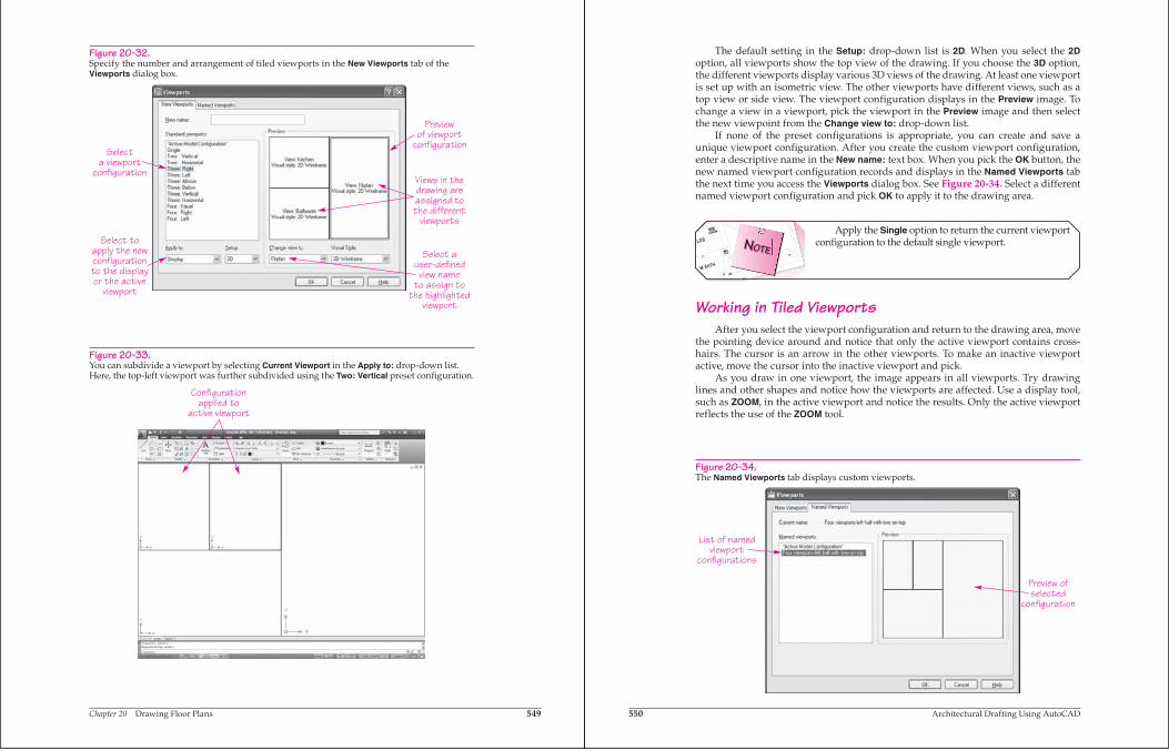
Figure 20-32.Specify the number and arrangement of tiled viewports in the New Viewports tab of the Viewports dialog box.
Previewof viewport
configuration
Views in thedrawing areassigned tothe different
viewports
Select auser-defined
view nameto assign to
the highlightedviewport
Selecta viewport
configuration
Select toapply the newconfigurationto the displayor the active
viewport
Figure 20-33.You can subdivide a viewport by selecting Current Viewport in the Apply to: drop-down list. Here, the top-left viewport was further subdivided using the Two: Vertical preset configuration.
Configurationapplied to
active viewport
550 Architectural Drafting Using AutoCAD
The default setting in the Setup: drop-down list is 2D. When you select the 2Doption, all viewports show the top view of the drawing. If you choose the 3D option, the different viewports display various 3D views of the drawing. At least one viewport is set up with an isometric view. The other viewports have different views, such as a top view or side view. The viewport configuration displays in the Preview image. To change a view in a viewport, pick the viewport in the Preview image and then select the new viewpoint from the Change view to: drop-down list.
If none of the preset configurations is appropriate, you can create and save a unique viewport configuration. After you create the custom viewport configuration, enter a descriptive name in the New name: text box. When you pick the OK button, the new named viewport configuration records and displays in the Named Viewports tab the next time you access the Viewports dialog box. See Figure 20-34. Select a different named viewport configuration and pick OK to apply it to the drawing area.
LLIINN..
MMEE DD..
CC AABB ..
2222""xx3300""
AATTTT IICC
AACC CC EE SS SS
77
88
99
2
BB
HHBB
99
CC LLOOSS
MM BB AATTHH
NOTE
Apply the Single option to return the current viewport configuration to the default single viewport.
Working in Tiled ViewportsAfter you select the viewport configuration and return to the drawing area, move
the pointing device around and notice that only the active viewport contains cross-hairs. The cursor is an arrow in the other viewports. To make an inactive viewport active, move the cursor into the inactive viewport and pick.
As you draw in one viewport, the image appears in all viewports. Try drawing lines and other shapes and notice how the viewports are affected. Use a display tool, such as ZOOM, in the active viewport and notice the results. Only the active viewport reflects the use of the ZOOM tool.
Figure 20-34.The Named Viewports tab displays custom viewports.
List of namedviewport
configurations
Preview ofselected
configuration
Chapter 20 Drawing Floor Plans 551
Joining Tiled ViewportsUse the Join Viewports tool to join two viewports. When you select the Join
Viewports tool, AutoCAD prompts you to select the dominant viewport. Select the viewport that has the view you want to display in the joined viewport, or press [Enter]to select the active viewport. Then select the viewport to join with the dominant view-port. AutoCAD “glues” the two viewports together and retains the dominant view.
LLIINN..
MMEE DD..
CC AABB ..
2222""xx3300""
AATTTT IICC
AACC CC EE SS SS
77
88
99
2
BB
HHBB
99
CC LLOOSS
MM BB AATTHH
NOTE
The two viewports you join cannot create an L-shaped viewport. The adjoining edges of the viewports must be the same size in order to join them.
Exercise 20-10Go to the student Web site at www.g-wlearning.com/CAD to complete Exercise 20-10.
Chapter TestAnswer the following questions. Write your answers on a separate sheet of paper or go to the student Web site at www.g-wlearning.com/CAD to complete the electronic chapter test.
1. Briefly describe how a floor plan is created. 2. Calculate the exact wall thickness for a 2 × 6 stud wall with 1/2″ gypsum on the
inside, and 1/2″ sheathing and 1/2″ siding on the outside. 3. What is the advantage of drawing the perimeter walls as a polyline as opposed
to a line? 4. What is the advantage of creating a window block as a real block as opposed to
a unit block? 5. Define riser, as related to stairs. 6. Define tread, as related to stairs. 7. Calculate the total rise if the main floor to ceiling height is 8′-1″, the upstairs floor
has 2 × 10 joists, and the second floor has 1″ of subfloor and finish floor material. Show your calculations.
8. If a maximum 7″ rise is suggested, calculate the number of risers in the stairs for the total rise calculated in the previous question. Show your calculations.
9. How many treads are needed for the stairs in the previous two questions? Show your calculations.
10. What is casework? 11. Give another term used for upper cabinets. 12. Briefly describe each of the five dimensioning levels. 13. Explain the difference between general notes and specific notes. 14. Identify the function of the VIEW tool. 15. How do you create a named view of the current screen display? 16. How do you display an existing view? 17. What type of viewport is created in model space? 18. How can you specify whether a new viewport configuration applies to the entire
drawing window or the active viewport? 19. Explain the procedures and conditions that need to exist for joining viewports.
Ribbon
View> Viewports
Join Viewports
552 Architectural Drafting Using AutoCAD
Draw
ing
Prob
lem
s —
Chap
ter 2
0
Drawing ProblemsThe problems in this chapter continue the process of developing a set of working drawings for the four projects, started in Chapter 16. In this chapter, you will create floor plans for the projects. Create or import blocks as necessary to add floor plan symbols. Place all objects on appropriate layers. Complete each problem according to the specific instructions provided. When object dimensions are not provided, draw features proportional to the size and location of features shown, and approximate the size of features using your own practical experience and measurements, if available.
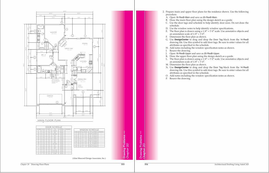
1. Prepare a floor plan for the single-level residence shown. Use the following procedure.A. Open 16-ResA and save as 20-ResA.B. Draw the floor plan using the design sketch as a guide.C. Use the door and window tags and schedules to help identify door and window
sizes. Do not draw the schedules.D. The floor plan is drawn using a 1/4″ = 1′-0″ scale. Use annotative objects and
an annotation scale of 1/4″ = 1′-0″.E. Dimension the floor plan as shown.F. Use DesignCenter to drag and drop the Door Tag and Window Tag blocks from
the 14-ResA drawing file. Use these symbols to add door and window tags. Be sure to enter values for all attributes as specified in the schedules.
G. Add notes.H. Resave the drawing.
Chapter 20 Drawing Floor Plans 553
Draw
ing
Prob
lem
s —
Chap
ter 2
0
(Alan Mascord Design Associates, Inc.)
554 Architectural Drafting Using AutoCAD
Draw
ing
Prob
lem
s —
Chap
ter 2
0
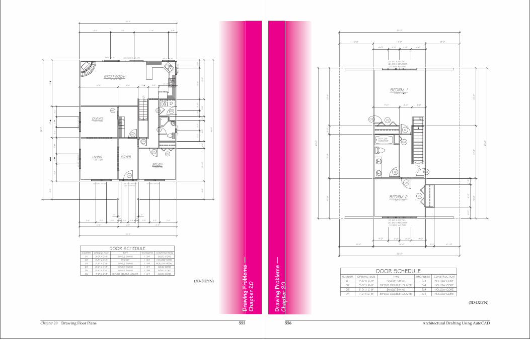
2. Prepare main and upper floor plans for the residence shown. Use the following procedure.A. Open 16-ResB-Main and save as 20-ResB-Main.B. Draw the main floor plan using the design sketch as a guide.C. Use the door tags and schedule to help identify door sizes. Do not draw the
schedule.D. Use the window notes to help identify window specifications.E. The floor plan is drawn using a 1/4″ = 1′-0″ scale. Use annotative objects and
an annotation scale of 1/4″ = 1′-0″.F. Dimension the floor plan as shown.G. Use DesignCenter to drag and drop the Door Tag block from the 14-ResB
drawing file. Use this symbol to add door tags. Be sure to enter values for all attributes as specified in the schedule.
H. Add notes including the window specification notes as shown.I. Resave the drawing.J. Open 16-ResB-Upper and save as 20-ResB-Upper.K. Draw the upper floor plan using the design sketch as a guide.L. The floor plan is drawn using a 1/4″ = 1′-0″ scale. Use annotative objects and
an annotation scale of 1/4″ = 1′-0″.M. Dimension the floor plan as shown. N. Use DesignCenter to drag and drop the Door Tag block from the 14-ResB
drawing file. Use this symbol to add door tags. Be sure to enter values for all attributes as specified in the schedule.
O. Add notes including the window specification notes as shown.P. Resave the drawing.
Chapter 20 Drawing Floor Plans 555
Draw
ing
Prob
lem
s —
Chap
ter 2
0(3D-DZYN)
556 Architectural Drafting Using AutoCAD
Draw
ing
Prob
lem
s —
Chap
ter 2
0
(3D-DZYN)
Chapter 20 Drawing Floor Plans 557
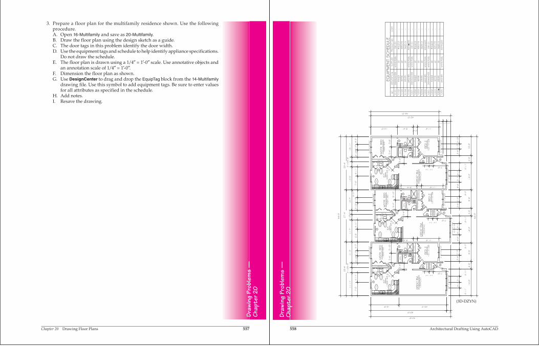
3. Prepare a floor plan for the multifamily residence shown. Use the following procedure.A. Open 16-Multifamily and save as 20-Multifamily.B. Draw the floor plan using the design sketch as a guide.C. The door tags in this problem identify the door width.D. Use the equipment tags and schedule to help identify appliance specifications.
Do not draw the schedule.E. The floor plan is drawn using a 1/4″ = 1′-0″ scale. Use annotative objects and
an annotation scale of 1/4″ = 1′-0″.F. Dimension the floor plan as shown. G. Use DesignCenter to drag and drop the EquipTag block from the 14-Multifamily
drawing file. Use this symbol to add equipment tags. Be sure to enter values for all attributes as specified in the schedule.
H. Add notes.I. Resave the drawing.
Draw
ing
Prob
lem
s —
Chap
ter 2
0
558 Architectural Drafting Using AutoCAD
Draw
ing
Prob
lem
s —
Chap
ter 2
0
(3D-DZYN)
Chapter 20 Drawing Floor Plans 559
Draw
ing
Prob
lem
s —
Chap
ter 2
0
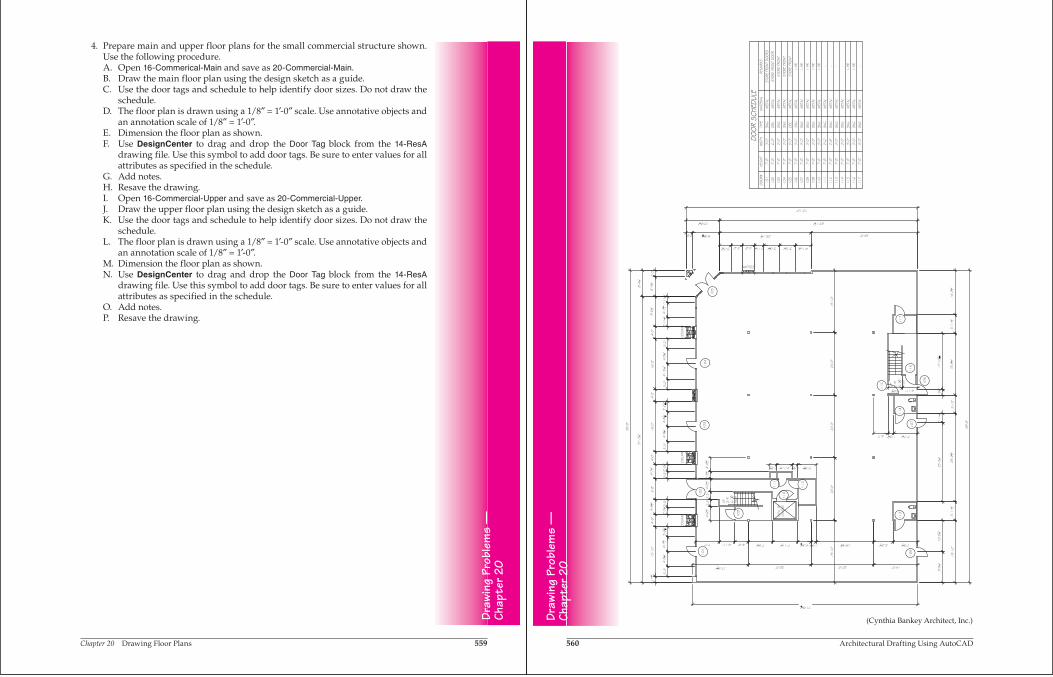
4. Prepare main and upper floor plans for the small commercial structure shown. Use the following procedure.A. Open 16-Commerical-Main and save as 20-Commercial-Main.B. Draw the main floor plan using the design sketch as a guide.C. Use the door tags and schedule to help identify door sizes. Do not draw the
schedule.D. The floor plan is drawn using a 1/8″ = 1′-0″ scale. Use annotative objects and
an annotation scale of 1/8″ = 1′-0″.E. Dimension the floor plan as shown. F. Use DesignCenter to drag and drop the Door Tag block from the 14-ResA
drawing file. Use this symbol to add door tags. Be sure to enter values for all attributes as specified in the schedule.
G. Add notes.H. Resave the drawing.I. Open 16-Commercial-Upper and save as 20-Commercial-Upper.J. Draw the upper floor plan using the design sketch as a guide.K. Use the door tags and schedule to help identify door sizes. Do not draw the
schedule.L. The floor plan is drawn using a 1/8″ = 1′-0″ scale. Use annotative objects and
an annotation scale of 1/8″ = 1′-0″.M. Dimension the floor plan as shown. N. Use DesignCenter to drag and drop the Door Tag block from the 14-ResA
drawing file. Use this symbol to add door tags. Be sure to enter values for all attributes as specified in the schedule.
O. Add notes.P. Resave the drawing.
560 Architectural Drafting Using AutoCAD
Draw
ing
Prob
lem
s —
Chap
ter 2
0
101
102
103
104
105
106
107
108
109
110
111
112
113
114
115
116
117
(Cynthia Bankey Architect, Inc.)
Chapter 20 Drawing Floor Plans 561
118
119
120
121
122
123
124
125
126
127
128
129
130
(Cynthia Bankey Architect, Inc.) Draw
ing
Prob
lem
s —
Chap
ter 2
0
562 Architectural Drafting Using AutoCAD
Draw
ing
Prob
lem
s —
Chap
ter 2
0
The Autodesk User Group International (AUGI) Web site (www.augi.com) is a useful resource for AutoCAD users. It offers valuable information about using Autodesk products and peer support from other AutoCAD users.


