Ch 6 QRA -...
87
QUANTITATIVE RISK ASSESSMENT 6.0 INTRODUCTION QRA study for, M/s. Aquapharm Pvt. Ltd. has been carried out based on data provided by them. The study has been carried out in accordance with the International codes of practices using PHAST (Process Hazard Analysis Software Tool) – 6.53 software. The latest version of the renowned PHAST Risk software package of DNV is used for carrying out the risk analysis. The full terms of potential hazardous scenarios and consequence events associated with the installation and operation was considered in the analysis. Based on the operations to be carried at the plant, the Risk Analysis, affected distances and the damage of property and population from the identified scenarios considering the Maximum Credible Loss Scenario (MCLS) & Worst case scenario. Maximum credible loss scenarios have been worked based on the inbuilt safety systems and protection measures to be provided for the operation of the facility & the Worst case scenario i.e. 100% catastrophic rupture have been worked out based on failure of the inbuilt safety system. We have assumed Maximum credible loss scenario (MCLS) i.e. Nozzle failure and Worst case Scenario i.e. catastrophic rupture as per the guidelines suggested by DNV – UK. Similarly, maximum inventory at the time of failure is assumed. 6.1 OBJECTIVE OF THE STUDY The main objective QRA (Quantitative Risk Analysis) is to determine the potential risks of major disasters having damage potential to life and property and provide a scientific basis for decision makers to be satisfied about the safety levels of the facilities to be set up. This is achieved by the following: Identification of hazards that could be realized from process plant. Identify the potential failure scenarios that could occur within the facility. To Asses, the potential risks associated with identified hazards to which the plant and its personal and community outside may be subjected. Consequences analysis of various hazards is carried out to determine the vulnerable zones for each probable accident scenario. Evaluate the process hazards emanating from the identified potential accident scenarios.
Transcript of Ch 6 QRA -...

QUANTITATIVE RISK ASSESSMENT
6.0 INTRODUCTION
QRA study for, M/s. Aquapharm Pvt. Ltd. has been carried out based on data provided by
them. The study has been carried out in accordance with the International codes of
practices using PHAST (Process Hazard Analysis Software Tool) – 6.53 software. The latest
version of the renowned PHAST Risk software package of DNV is used for carrying out the
risk analysis.
The full terms of potential hazardous scenarios and consequence events associated with
the installation and operation was considered in the analysis. Based on the operations to
be carried at the plant, the Risk Analysis, affected distances and the damage of property
and population from the identified scenarios considering the Maximum Credible Loss
Scenario (MCLS) & Worst case scenario. Maximum credible loss scenarios have been
worked based on the inbuilt safety systems and protection measures to be provided for
the operation of the facility & the Worst case scenario i.e. 100% catastrophic rupture have
been worked out based on failure of the inbuilt safety system.
We have assumed Maximum credible loss scenario (MCLS) i.e. Nozzle failure and Worst
case Scenario i.e. catastrophic rupture as per the guidelines suggested by DNV – UK.
Similarly, maximum inventory at the time of failure is assumed.
6.1 OBJECTIVE OF THE STUDY
The main objective QRA (Quantitative Risk Analysis) is to determine the potential risks of
major disasters having damage potential to life and property and provide a scientific
basis for decision makers to be satisfied about the safety levels of the facilities to be set
up. This is achieved by the following:
Identification of hazards that could be realized from process plant.
Identify the potential failure scenarios that could occur within the facility.
To Asses, the potential risks associated with identified hazards to which the plant
and its personal and community outside may be subjected. Consequences
analysis of various hazards is carried out to determine the vulnerable zones for
each probable accident scenario.
Evaluate the process hazards emanating from the identified potential accident
scenarios.

Analyze the damage effects to the surroundings due to such accidents.
Conclusion and Recommendation to mitigate measures to reduce the hazard /
risks.
To provide guidelines for the preparation of On-site response plan.
6.2 SCOPE OF THE STUDY
Following flammable chemicals or solvents stored, used and handled in the premises.
S. No Flammable
solvents/Material Hazards
Flash Point
(°C)
Approx
Quantity (KL)
1 Acetic Acid Flammable (Pool fire, Jet fire,
flash fire, Max Concentration) 39 38
2 Amines Flammable (Pool fire, Jet fire,
flash fire, Max Concentration ) - 6 100
3 Ammonia Flammable (Pool fire, Jet fire,
flash fire, overpressure ) -- 15
6.3 USE OF QRA RESULTS
The techniques used for risk prediction within the QRA have inherent uncertainties
associated with them due to the necessary simplifications required. In addition, QRA
incorporates a certain amount of subjective engineering judgment and the results are
subject to levels of uncertainty. For this reason, the results should not be used as the sole
basis for decision making and should not drive deviations from sound engineering
practice. The results should be used as a tool to aid engineering judgment and, if used in
this way, can provide valuable information during the decision making process.
The QRA results are dependent on the assumptions made in the calculations, which are
clearly documented throughout the following sections of this report. Conservative
assumptions have been used, which helps to remove the requirement for detailed analysis
of the uncertainty. The results show the significant contributions to the overall risk and
indicate where worthwhile gains may be achieved if further enhancement of safety is
deemed necessary.
6.4 SOFTWARE USED
PHAST 6.53 (latest version) has been used for consequence analysis include discharge and
dispersion calculations.

6.5 METEOROLOGICAL CONDITIONS
The consequences of released toxic or flammable material are largely dependent on the
prevailing weather conditions. For the assessment of major scenarios involving release of
toxic or flammable materials, the most important meteorological parameters are those
that affect the atmospheric dispersion of the escaping material. The crucial variables are
wind direction, wind speed, atmospheric stability and temperature. Rainfall does not have
any direct bearing on the results of the risk analysis; however, it can have beneficial
effects by absorption / washout of released materials. Actual behavior of any release
would largely depend on prevailing weather condition at the time of release. For the
present study we use the metrological data of the Savli Village.
6.6 ATMOSPHERIC PARAMETERS
The Climatological data which have been used for the study is summarized below:
Table 6.1: Climatological data
S. No. Parameter Max Min. Annual Average
1. Ambient Temperature (°C) 42 22 33
2. Relative Humidity (%) 50 27 38.5
The average value of the atmospheric parameters is assumed for the study.
6.6.1 Wind Speed and Wind Direction
The wind speed and wind direction data which have been used for the study is
summarized below:
Wind Speed : 1.5 m/s & 5 m/s
Atmospheric Stability : D and F
Wind Direction : _____
6.6.2 Weather Category
One of the most important characteristics of atmosphere is its stability. Stability of
atmosphere is its tendency to resist vertical motion or to suppress existing turbulence. This
tendency directly influences the ability of atmosphere to disperse pollutants emitted into it
from the facilities. In most dispersion scenarios, the relevant atmospheric layer is that

nearest to the ground, varying in thickness from a few meters to a few thousand meters.
Turbulence induced by buoyancy forces in the atmosphere is closely related to the
vertical temperature gradient.
Temperature normally decreases with increasing height in the atmosphere. The rate at
which the temperature of air decreases with height is called Environmental Lapse Rate
(ELR). It will vary from time to time and from place to place. The atmosphere is said to be
stable, neutral or unstable according to ELR is less than, equal to or greater than Dry
Adiabatic Lapse Rate (DALR), which is a constant value of 0.98°C/100 meters.
Pas-quill stability parameter, based on Pas-quill – Gifford categorization, is such a
meteorological parameter, which describes the stability of atmosphere, i.e., the degree of
convective turbulence. Pas-quill has defined six stability classes ranging from `A'
(extremely unstable) to `F' (moderately stable). Wind speeds, intensity of solar radiation
(daytime insulation) and nighttime sky cover have been identified as prime factors
defining these stability categories.
When the atmosphere is unstable and wind speeds are moderate or high or gusty, rapid
dispersion of pollutants will occur. Under these conditions, pollutant concentrations in air
will be moderate or low and the material will be dispersed rapidly. When the atmosphere
is stable and wind speed is low, dispersion of material will be limited and pollutant
concentration in air will be high. In general, worst dispersion conditions (i.e. contributing to
greater hazard distances) occur during low wind speed and very stable weather
conditions.
6.7 METHODOLOGY ADOPTED FOR CONSEQUENCE ANALYSIS
Consequences of loss of containment can lead to hazardous situation in any industry
handling potentially hazardous materials. Following factors govern the severity of
consequence of the loss of containment.
Intrinsic properties; flammability, instability and toxicity.
Dispersive energy; pressure, temperature and state of matter.
Quantity present
Environmental factors; topography and weather.

Consequence analysis and calculations are effectively performed by computer software
using models validated over a number of applications. Consequence modeling is carried
out by PHAST (version 6.53) of DNV Software, UK.
PHAST uses the Unified Dispersion Model (UDM) capable of describing a wide range of
types of accidental releases. The Model uses a particularly flexible form, allowing for
sharp-edged profiles, which become more diffuse downwind.
PHAST contains data for a large number of chemicals and allows definition of mixtures of
any of these chemicals in the required proportion. The calculations by PHAST involve
following steps for each modeled failure case:
Run discharge calculations based on physical conditions and leak size.
Model first stage of release (for each weather category).
Determine vapor release rate by flashing of liquid and pool evaporation rate.
Dispersion modeling taking into account weather conditions.
In case of flammable release, calculate size of effect zone for fire and explosion.
The hazardous materials considered in this study are mostly flammable liquids.
Flow chart for consequence analysis is shown in the form of event tree for release
of flammable liquid.
6.8 HAZARDS OF MATERIALS
Definitions
The release of flammable gas or liquid can lead to different types of fire or explosion
scenarios. These depend on the material released, mechanism of release, temperature
and pressure of the material and the point of ignition. Types of flammable effects are as
follows.
a. Pool fire
The released flammable material which is a liquid stored below its normal boiling point, will
collect in a pool. The geometry of the pool will be dictated by the surroundings. If the
liquid is stored under pressure above its normal boiling point, then a fraction of the liquid
will flash into vapor and the remaining portion will form a pool in the vicinity of the release

point. Once sustained combustion is achieved, liquid fires quickly reach steady state
burning. The heat release rate is a function of the liquid surface area exposed to air. An
unconfined spill will tend to have thin fuel depth (typically less than 5 mm) which will result
in slower burning rates. A confined spill is limited by the boundaries (e.g. dyked area) and
the depth of the resulting pool is greater than that for an unconfined spill.
b. Flash fire:
It occurs when a vapor cloud of flammable material burns. The cloud is typically ignited
on the edge and burns towards the release point. The duration of flash fire is very short
(seconds), but it may continue as jet fire if the release continues. The overpressures
generated by the combustion are not considered significant in terms of damage
potential to persons, equipment or structures. The major hazard from flash fire is direct
flame impingement. Typically, the burn zone is defined as the area the vapor cloud
covers out to half of the LFL. This definition provides a conservative estimate, allowing for
fluctuations in modeling. Even where the concentration may be above the UFL, turbulent
induced combustion mixes the material with air and results in flash fire.
c. Jet Fire:
Jet flames are characterized as high-pressure release of gas from limited openings (e.g.
due to small leak in a vessel or broken drain valve). Boiling liquid expanding vapor
explosion (BLEVE) or fireball: A fireball is an intense spherical fire resulting from a sudden
release of pressurized liquid or gas that is immediately ignited. The best known cause of a
fireball is a boiling liquid expanding vapor explosion (BLEVE). Fireball duration is typically 5
– 20 seconds.
d. Vapor cloud explosion
When a large quantity of flammable vapor or gas is released, mixes with air to produce
sufficient mass in the flammable range and is ignited, the result is a vapor cloud explosion
(VCE). Without sufficient air mixing, a diffusion-controlled fireball may result without
significant overpressures developing. The speed of flame propagation must accelerate
as the vapor cloud burns. Without this acceleration, only a flash fire will result.

6.8.1 HAZARDS ASSOCIATED WITH TOXIC MATERIALS
It is necessary to specify suitable concentration of the toxic substance under study to form
the end-point for consequence calculations. The considerations for specifying the end-
points for the hazardous material involved in the failure scenario are described in the
following paragraphs. American Industrial Hygiene Association (AIHA) has issued
Emergency Response Planning Guidelines (ERPG) for many chemicals.
• ERPG-1 is the maximum airborne concentration below which it is believed that
nearly all individuals could be exposed for up to 1 hour without experiencing other than
mild transient adverse health effects or perceiving a clearly defined, objectionable odour.
• ERPG-2 is the maximum airborne concentration below which it is believed that
nearly all individuals could be exposed for up to 1 hour without experiencing or
developing irreversible or other serious health effects or symptoms, which could impair an
individual's ability to take protective action.
• ERPG-3 is the maximum airborne concentration below which it is believed that
nearly all individuals could be exposed for up to 1 hour without experiencing or
developing life-threatening health effects.
Toxic limit values as Immediately Dangerous to Life or Health (IDLH) concentrations are
issued by US National Institute for Occupational Safety and Health (NIOSH). An IDLH level
represents the maximum airborne concentration of a substance to which a healthy male
worker can be exposed as long as 30 minutes and still be able to escape without loss of
life or irreversible organ system damage. IDLH values also take into consideration acute
toxic reactions such as severe eye irritation, which could prevent escape. IDLH values are
used in selection of breathing apparatus.
TLV: Threshold Limit Value – is the permitted level of exposure for a given period on a
weighted average basis (usually 8 hrs for 5 days in a week).
STEL: A Short Term Exposure Limit (STEL) is defined by ACGIH as the concentration to which
workers can be exposed continuously for a short period of time without suffering from:
Irritation
chronic or irreversible tissue damage

Narcosis of sufficient degree to increase the likelihood of accidental injury, impair
self-rescue or materially reduce work efficiency.
It is permitted Short Time Exposure Limit usually for a 15-minute exposure.
IDLH: IDLH is an acronym for Immediately Dangerous to Life or Health. This refers to a
concentration, formally specified by a regulatory value, and defined as the maximum
exposure concentration of a given chemical in the workplace from which one could
escape within 30 minutes without any escape-impairing symptoms or any irreversible
health effects. This value is normally referred to in respirator selection.
LCLo: Lethal Concentration Low (LCLo) value is the lowest concentration of a material in
air reported to have caused the death of animals or humans. The exposure may be acute
or chronic. This is also called the lowest concentration causing death, lowest detected
lethal concentration, and lethal concentration low.
LDLo: LDLo is closely related to the LC50 value which is the concentration which kills half of
the test animals under controlled conditions. This value applies to vapors, dusts, mists and
gases. Solids and liquids use the closely related LDLo value for routes other than inhalation
TCLo: Toxic Concentration Low quantity at which a water-soluble, liquid, or gaseous
substance produces harmful effects in specified test specie over a certain exposure
period.
6.8.2 Damage Criteria
Damage estimates due to thermal radiations and overpressure have been arrived at by
taking in to consideration the published literature on the subject. The consequences can
then be visualized by the superimposing the damage effects zones on the proposed plan
site and identifying the elements within the project site as well as in the neighboring
environment, which might be adversely affected, should one or more hazards materialize
in real life.
6.8.3 Thermal Damage
The effect of thermal radiation on people is mainly a function of intensity of radiation and
exposure time. The effect is expressed in terms of the probability of death and different
degrees of burn. The following tables give the effect of various levels of heat flux.
6.8.3.1 Damage Due to Radiation Intensity

Table 6.2: Damage Due to Radiation Intensity
RADIATION
KW/m2 DAMAGE TO EQUIPEMENT DAMAGE TO PEOPLE
1.2 Solar heat at noon.
1.6 *** Minimum level of pain threshold.
2.0 PVC insulated cables damaged Minimum level of pain threshold.
4.0 *** Causes pain if duration is longer
than 20 sec. But blistering is unlikely.
6.4 *** Pain threshold reached after 8 sec.
Second degree burns after 20 sec.
12.5
Minimum energy to ignite wood
with a flame; Melts plastic
tubing.
1% lethality in one minute.
First degree burns in 10 sec.
16.0 *** Severe burns after 5 sec.
25.0
Minimum energy to ignite wood
at identifying long exposure
without a flame.
100% lethality in 1 minute.
Significant injury in 10 sec.
37.5 Severe damage to plant
100% lethality in 1 minute.
50% lethality in 20 sec.
1% lethality in 10 sec.
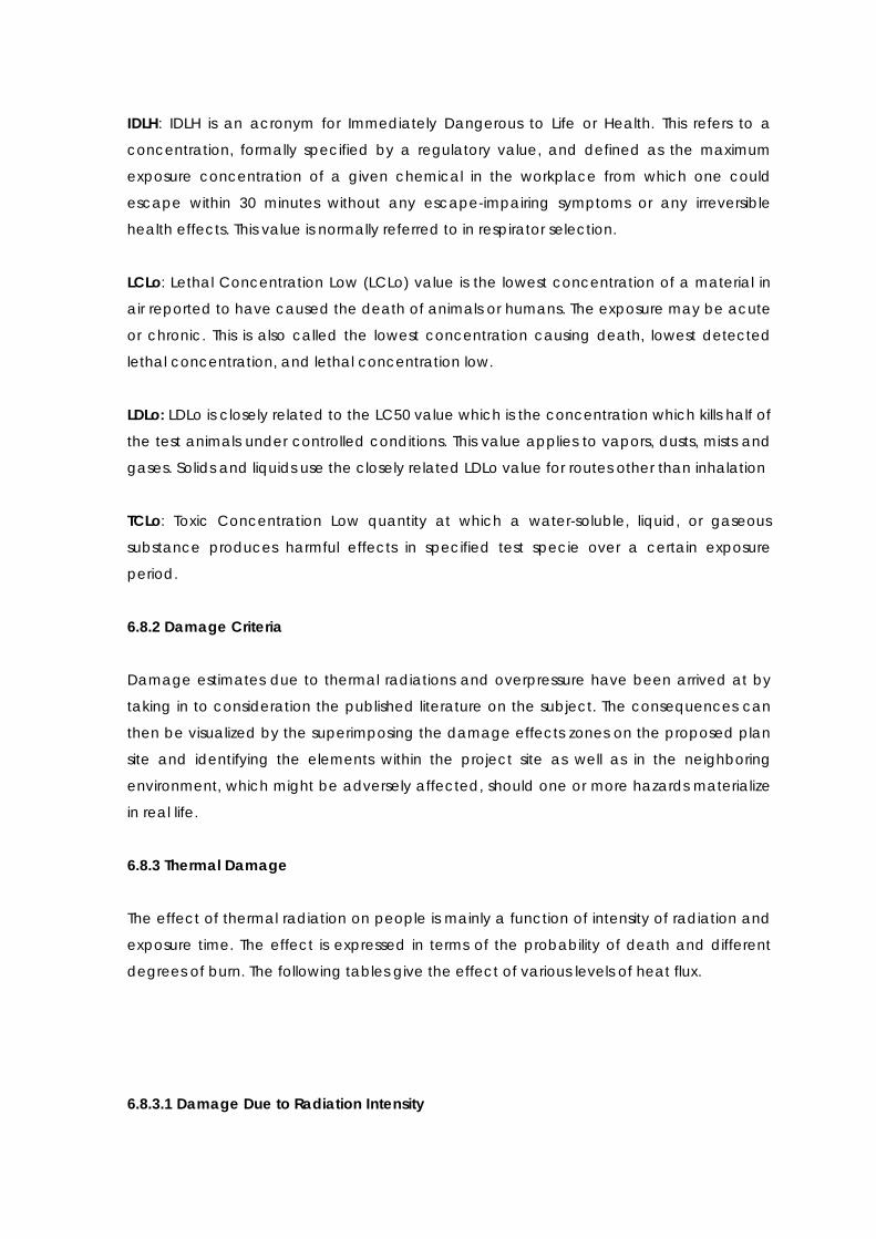
6.8.3.2 Fatal radiation exposure levels
Table 6.3: Fetal radiation Exposure Level
RADIATION LEVEL
kW/m2
FATALITY
1% 50% 99%
EXPOSURE IN SECONDS
4.0 150 370 930
12.5 30 80 200
37.5 8 20 50
6.8.4 Overpressure Damage:
Table 6.4: Overpressure Damage Criteria
OVER PRESSURE
(mbar)
MECHANICAL DAMAGE TO
EQUIPMENTS DAMAGE TO PEOPLE
300 Heavy damage to plant & structure
1% death from lung damage
>50% eardrum damage
>50% serious wounds from
flying objects
100 Repairable damage
>1% eardrum damage
>1% serious wounds from flying
objects
30 Major glass damage Slight injury from flying glass
10 10% glass damage ***

6.8.4.1 Over pressure damage: (In Details)
Table 6.5: Over pressure Damage
OVER PRESSURE MECHANICAL DAMAGE TO EQUIPMENTS
Bar KPa
0.0014 0.14 Annoying noise (137 dB if of low frequency 10–15 Hz).
0.0021 0.21 Occasional breaking of large glass windows already under strain.
0.0028 0.28 Loud noise (143 dB), sonic boom, glass failure.
0.0069 0.69 Breakage of small windows under strain.
0.0103 1.03 Typical pressure for glass breakage.
0.0207 2.07 Safe distance" (probability 0.95 of no serious damage below this
value); projectile limit; some damage to house ceilings; 10% window
glass broken.
0.0276 2.76 Limited minor structural damage.
0.03-
0.069
3.4-6.9 Large and small windows usually shattered; occasional .damage to
window frames.
0.048 4.8 Minor damage to house structures.
0.069 6.9 Partial demolition of houses, made uninhabitable.
0.069-
0.138
6.9-
13.8
Corrugated asbestos shattered; corrugated steel or aluminum panels,
fastenings fail, followed by buckling; wood panels (standard
housing)fastenings fail, panels blown in.
0.09 9.0 Steel frame of clad building slightly distorted.
0.138 13.8 Partial collapse of walls and roofs of houses.
0.138-
0.207
13.8-
20.7
Concrete or cinder block walls, not reinforced, shattered.
0.158 15.8 Lower limit of serious structural damage.
0.172 17.2 50% destruction of brickwork of houses.
0.207 20.7 Heavy machines (3000 lb) in industrial building suffered little damage;
steel frame building distorted and pulled away from foundations.
0.207-
0.276
20.7-
27.6
Frameless, self-framing steel panel building demolished; rupture of oil
storage tanks.
0.276 27.6 Cladding of light industrial buildings ruptured.
0.345 34.5 Wooden utility poles snapped; tall hydraulic press (40,000 lb) in
building slightly damaged.
0.345-
0.482
34.5-
48.2
Nearly complete destruction of houses.
0.482 48.2 Loaded, lighter weight (British) train wagons overturned.

0.482-
0.551
48.2-
55.1
Brick panels, 8–12 in. thick, not reinforced, fail by shearing or flexure.
0.62 62.0 Loaded train boxcars completely demolished.
0.689 68.9 Probable total destruction of buildings; heavy machine tools (7,000 lb)
moved and badly damaged, very heavy machine tools (12,000 lb)
survive.
0.689 68.9 Probable total destruction of buildings; heavy machine tools (7,000 lb)
moved and badly damaged, very heavy machine tools (12,000 lb)
survive.
20.68 2068 Limit of crater lip.
6.9 CONSEQUENCE ANALYSIS
6.9.1 Introduction
The consequence analysis is carried out to determine the extent of spread (dispersion) by
accidental release which may lead to jet fire, pool fire, tank fire resulting into generating
heat radiation, overpressures, explosions etc.
In order to form an opinion on potentially serious hazardous situations and their
consequences, consequence analysis of potential failure scenarios is conducted. It is
qualitative analysis of hazards due to various failure scenarios. In consequence analysis,
each failure case is considered in isolation and damage effects predicted, without taking
into the account of the secondary events or failures it may cause, leading to a major
disastrous situation. The results of consequence analysis are useful in developing disaster
management plan and in developing a sense of awareness among operating and
maintenance personnel. It also gives the operating personnel and population living in its
vicinity, an understanding of the hazard they are posed to.

6.9.2 Event Outcomes
Upon release of flammable / toxic gas & liquids, the hazards could lead to various events
which are governed by the type of release, release phase, ignition etc. PHAST has an in-
built event tree for determining the outcomes which are based on two types of releases
namely continuous and instantaneous. Leaks are considered to be continuous releases
whereas, ruptures are considered to be instantaneous releases. These types of releases
are further classified into those which have a potential for rain-out and those which do
not. Whether the release would leak to a rain-out or not depends upon droplet modeling
which is the main cause of formation of pools. Fig 6.1, 6.2, 6.3 and 6.4 presents the event
trees utilized by PHAST to generate the event outcomes.
Figure 6.1: Event Tree for continuous release without rain-out (from PHAST)

Figure 6.2: Event Tree for Instantaneous release without rain-out (from PHAST)
Figure 6.3: Event Tree for continuous release with rain-out (from PHAST)

Figure 6.4: Event Tree for Instantaneous release with rain-out (from PHAST)
6.9.3 Modes of Failure
There are various potential causes and sources of leakage. This may be by way of failures
of equipment or piping, due to pump seal failure, instrument tubing giving way, failure of
the pipes, failure of process vessels etc. Following Table represents general mechanism for
loss of containment for Piping and fitting, instruments, and human error.

(A). Piping and Fitting
Table 6.6: Piping and Fitting
Ref.
No.
LOSS OF
CONTAINMENT
EXAMPLES OF POSSIBLE BASIC CAUSE REMARKS
A.1 Flange/Gasket Leaks - Incorrect gasket installed, e.g.
incorrect material, incorrect size
(thickness and diameter).
- Incorrect installation, e.g. flange
faces not cleaned, flanged face
damaged, incorrectly tightened
bolts, incorrect bolts used.
- Flange replacement without
gasket.
Possible flame
impingement and
localized heating of
adjacent equipment.
A.2 Pipe Overstress
Causing Fracture
- Inappropriate use of design
codes.
- Error in stress analysis calculations.
- Lack of inspection during pipe
erection, e.g. excessive cold pull.
- Pipe testing incorrectly carried
out.
- Incorrect setting of spring hangers
and pipe supports and sliding shoes
not free to move.
- Pipe not hydro tested because of
bore size (or considered not critical)
and no secondary test procedures
carried out.
- Omission to test because systems
not clearly identified, or error in
documentation.
- Extreme temperature differential
in pipe work not catered for in design,
i.e. cold and hot streams
Pipe stresses would most
likely cause a flange
leak, unless there
existed a combination
of errors, e.g. installation
of rogue materials and
unsuitable pipe support,
or error in stress
calculation plus failure
to pressure test.
A.3 Over pressurization
of Pipe work
Causing Fracture
a) Inadequate Pressure Relief
- Relief valve ‘simmering’ and
hydrating, icing.
Careful attention
required for handling
hydrocarbons with

Ref.
No.
LOSS OF
CONTAINMENT
EXAMPLES OF POSSIBLE BASIC CAUSE REMARKS
- Incorrect setting of RV pressure.
- Incorrectly sized RV.
- Wrongly installed RV, e.g. due to
transferred tag No. : or installation of
incorrect spring material.
- Abuse of locking system and all
RVs isolated from system
- Excessive back pressure caused
by blockage of relief sub-headers
with sludge, ice/hydrate, etc.
- High pressure breakthrough into
low pressure systems, which have
inadequate relief capacity.
- Blockage of RVs with debris/fines,
e.g. mol sieve dust, or breakage of
screens/package/demister.
b) Excessive Surge Pressure /
Hammer
- Too rapid isolation or blockage of
liquid full lines, i.e., operator closing
isolation valve.
- Rapid blockage of liquid lines,
e.g. NRV failure.
- Lines not or inadequately
designed for two phase/slug flow.
- Too rapid opening of valves and
letdown of liquid under high
differential pressure.
- Rapid vaporization of cold liquid
in contact with hot fluid. (Rapid
phase transition).
c) Rupture Under Fire Conditions
“free” water.
Rigorous adherence to
procedures is essential.
Relief capacity should
always be adequate or
high integrity trip system
installed.
Potential problem
around mol sieve
vessels, absorbers,
columns and RVs.
Consider needs to
handle liquid slugs from
feed line when pigging
recommended.
Particular care required
at pig traps and at inlet
PCVs/bypass.
No remote
depressurizing system
available; requires
review.
Potential for
catastrophic rupture of
equipment,

Ref.
No.
LOSS OF
CONTAINMENT
EXAMPLES OF POSSIBLE BASIC CAUSE REMARKS
- Direct fire impingement without
any cooling (internal or external) or
failure to effectively depressure
equipment.
fragmentation and
fireball effects.
A-4 Failure of piping due
to fatigue or
vibration.
- Failure due to acoustic fatigue
arising from:-
E.g. failure to recognize problem
exists in particular areas, failure to
take adequate precautions
(selection of incorrect valve at design
stage or during maintenance,
inadequate line support). Improper
testing/inspection when in service,
failure to report abnormally high noise
levels (during normal and upset
conditions).
- Failure due to mechanical
vibration arising from:
e.g. failure to recognize problem,
inadequate support, failure to report
and minor excessive vibrations (under
all plant conditions), maintenance
error, (failure to correctly align
rotating equipment and test for
vibration prior to reinstatement?
- Failure due to pressure or thermal
cycling.
Vulnerable areas are
piping downstream of
PCVs and RVs operating
at very high pressures.
Particularly susceptible
is small bore pipe work
associated with
pressure letdown and
two phase flow systems
and compressors/
pumps.
Regeneration gas pipe
work and connections
to mol sieve vessels
merit particular
attention.
A.5 Failure of Pipe due
to Stress Corrosion of
Embrittlement
- Hydrogen
embrittlement/blistering. (Hydrogen
induced cracking).
Only stainless steel
equipment.
A.8 Failure of piping Due
to installation of
Wrong Materials
- Incorrect materials selection, e.g.
at design stage, from supplier or site
stores.
- Incorrect material installed, e.g.
Strict system for
supervision, inspection
and verification of
materials required

Ref.
No.
LOSS OF
CONTAINMENT
EXAMPLES OF POSSIBLE BASIC CAUSE REMARKS
improper supervision and
identification of materials after
withdrawal from stores.
during all modifications.
A.9 Failure of Piping Due
to low Temperature
Brittle fracture
- Rogue material used in
construction, wrong material
specified, or uncertainties in
material specification.
- Error in calculating minimum lower
design temperatures.
- Systems not designed for low
temperature, (e.g. on emergency
depressuring) and immediate
repressurising.
A number of systems
have been identified as
bring vulnerable,
particularly where
condensate at high
pressure may be
depressurized.
A.10 Failure of Piping (or
nozzles) Due to
External Forces or
Impact.
- Impact from equipment being
moved during maintenance.
- Impact of heavy lifting gear, e.g.
cranes.
- Impact from site transport, e.g.
construction traffic, fire tender.
- Impact on reinforced nozzle
causing fractures elsewhere, e.g.
valve, pump casing vessel.
Historically, failure of HP
process piping due to
mechanical impact is
confined mainly to small
bore piping.
Strict control over site
construction will of
course be necessary.
Any incident of impact
on pipe work during
construction must be
reported and damage
investigated.

(B) Human Error
Table 6.7: Human Error
Ref.
No.
LOSS OF
CONTAINMENT
EXAMPLES OF POSSIBLE BASIC CAUSE REMARKS
Loss of containment through human error has been assumed implicitly in the storage area
however examples or some typical operating and maintenance errors are included below:-
B.1 Operational Error - Failure or inability to close
instrument or sample valves.
- Failure or inability to close drain
and vent valves.
- Leaving safety trips/systems out of
commission after testing or
inspecting.
- Intentionally defeating trip
systems for reasons of production.
B.2 Error in De-
commissioning
- Inadvertent or unauthorized
opening of a pressurized system, e.g.
filters, vessels.
- Improver depressurizing and
purging of a system prior to isolation
or spading.
- Failure to effectively isolate all
process (and utility) and electrical
connections.
B.3 Error in Maintenance - Failure to maintain effective
isolation.
- Failure to report damage to
equipment during repair or
modification.
- Maintenance activities extended
to systems, which are `live’.
- Improper supervision of contract
maintenance staff, improper
maintenance.
B.4 Error in Re-
commissioning
- Failure to close vents/drains,
replace plugs.
- Improper or lack or purging of

Ref.
No.
LOSS OF
CONTAINMENT
EXAMPLES OF POSSIBLE BASIC CAUSE REMARKS
equipment e.g. sphere receiver
furnaces.
B.5 Supervision Error - Design error for modifications.
- Lack of supervision and control
e.g. Authorization of permits isolation.
- Failure to regularly test/inspect
e.g. trip/alarm system, safety
equipment.
Allure to regularly monitor e.g. noise
vibration, corrosion, stream
composition
6.9.4 Selected Failure Cases
Earlier, it was the practice to select a particular item in a unit as failure scenario, e.g.
rupture of reactor outlet pipe. Such selection is normally subjective on following
parameters:
Properties of material namely Toxic or Flammable.
The likely severity of consequence in the event of accidental release based on
inventory, operated pressure & operated temperature.
The probability of failure of various equipments such as valves, flanges, pipe,
pressure vessels etc. used in the plant.
Size of Release: For accidental releases identified for consequence analysis is 50mm
leakage. The scenarios are considered to be confined to those equipment failures which
involve the leakage of flammable or toxic products, of which the frequency of
occurrence and the severity of the consequences have been taken into consideration
and which may have a low probability of early detection.
Taking this factor into consideration, a list of selected failure cases was prepared based
on process knowledge, inventory, engineering judgment, and experience, past incidents
associated with such facilities and considering the general mechanisms for loss of
containment. Cases have been identified for the consequence analysis.

Consequence analysis and calculations are effectively performed by computer software
using models validated over a number of applications. Consequence modeling is carried
out by PHAST (version 6.53) of DNV Software, UK.
PHAST uses the Unified Dispersion Model (UDM) capable of describing a wide range of
types of accidental releases. The Model uses a particularly flexible form, allowing for
sharp-edged profiles, which become more diffuse downwind.
PHAST contains data for a large number of chemicals and allows definition of mixtures of
any of these chemicals in the required proportion. The calculations by PHAST involve
following steps for each modeled failure case:
6.9.4.1 Effect of Release
When hazardous material is released to atmosphere due to any reason, a vapor cloud is
formed. Direct cloud formation occurs when a gaseous or flashing liquid escapes to the
atmosphere. Release of hydrocarbons and toxic compounds to atmosphere may usually
lead to the following:
(a) Dispersion of hydrocarbon vapor with wind till it reaches its lower flammability limit (LFL)
or finds a source of ignition before reaching LFL, which will result in a flash fire or explosion.
(b) Spillage of liquid hydrocarbons will result in a pool of liquid, which will evaporate taking
heat from the surface, forming a flammable atmosphere above it. Ignition of this pool will
result in pool fire causing thermal radiation hazards.
(c) Lighter hydrocarbon vapor (e.g. Natural Gas) or Hydrogen disperses rapidly in the
downwind direction, being lighter than air. But comparatively heavier hydrocarbon vapor
cloud like that of LPG, Propylene or Ammonia will travel downwind along the ground. If it
encounters an ignition source before it is dispersed below the LFL, explosion of an
unconfined vapor cloud will generate blast waves of different intensities.
(d) A fireball or BLEVE (Boiling Liquid expanding Vapor Explosion) occurs when a vessel
containing a highly volatile liquid (e.g. LPG, Propylene etc) fails and the released large
mass of vapor cloud gets ignited immediately. It has damage potential due to high
intensity of radiation and generation of the overpressure waves, causing large-scale
damage to nearby equipment and structures.

(e) Catastrophic failure of tanks/ pressurized vessels, rotary equipment and valves etc.
can result in equipment fragments flying and hitting other equipment of the plant.
(f) Release of toxic compounds results in the toxic vapour cloud traveling over long
distances, affecting a large area, before it gets sufficiently diluted to harmless
concentration in the atmosphere.
(g) The material is in two phases inside the containment - liquid & vapor. Depending on
the location of the leak liquid or vapor will be released from the containment. If vapor is
released a vapor cloud will form by the mixing of the vapor and air. The size of the vapor
cloud will depend on the rate of release, wind speed; wind direction & atmospheric
stability will determine the dispersion and movement of the vapor cloud.
(h) If liquid is released there will be some flashing as the boiling point of liquid is below the
ambient temperature. The vapor formed by immediate flashing will behave as vapors
release. The liquid will fall on the ground forming a pool. There will be vaporization from
the pool due to the heat gained from the atmosphere & ground. There will be dispersion
and movement of vapor cloud formed by evaporation of liquid.
The behavior of material released by loss of containment depends on the following
factors:
(1) Physical properties of the material.
(2) Conditions of material in containment (pressure and temperature).
(3) Phase of material released (liquid or gas).
(4) Inventory of material released.
(5) Weather parameters (temperature, humidity, wind speed, atmospheric stability).
(6) Material with boiling point below ambient condition.
Statistical reports of consequence analysis are summarized below in Table 7. Similarly
pictorial presentations of consequence results are shown below the tabular report.
Table 6.8: Consequence results for Acetic Acid failure
S. No 1
Scenario description Leakage of Acetic Acid.

Weather data 1.5 m/s F 5 m/s D
Damage Distances (m)
Flash Fire
UFL 1.672 0.734051
LFL 1.95837 1.67103
LFL Fraction 2.56393 2.51443
Jet Fire (kW/m2)
4 29.9103 30.2126
12.5 5.19589 5.27517
37.5 Not Reached Not Reached
Pool fire (kW/m2)
4 87.0314 87.726
12.5 55.7739 56.227
37.5 39.4851 39.787
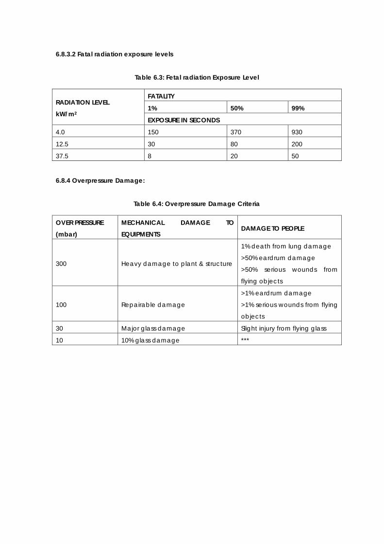
Table 6.9: Consequence results for Ammonia failure
S. No 2
Scenario description
Leakage of Ammonia
Weather data 1.5 m/s D 5 m /s F
Damage Distances (m)
Flash Fire
UFL 6.97011 7.20521
LFL 17.2437 14.4003
LFL Fraction 53.7567 33.6682
Jet Fire (kW/m2)
4 54.4412 47.5428
12.5 43.132 39.079
37.5 Not Reached Not Reached
Overpressure (bar)
0.02068 93.5569 49.6578
0.1379 61.278 35.089
0.2068 58.7256 33.9364
Pool fire (kW/m2)
4 153.706 151.375
12.5 102.95 108.109
37.5 67.1992 65.0112
Intensity Radii for Pool Fire- Acetic Acid Leak
GRAPH

Aqua pharm Exhibit-2_Plant Layout
Models
Ellipse @ 12.5 kW/m2
Ellipse @ 4 kW/m2
Radiation Level
Weather: 5 D
Study Folder: New PhastMicro
Model: 50 mm leak.
Material: DICHLOROMETHANE
Audit No: 223
Intensity Radii for Pool Fire
MAP
Flash Fire- Acetic Acid Leak
GRAPH

Aqua pharm Exhibit-2_Plant Layout
Models
159000 ppm
79500 ppm
Concentration
Weather: 5 D
Study Folder: New PhastMicro
Model: 50 mm leak.
Material: DICHLOROMETHANE
Audit No: 223
Flash Fire
MAP
Maximum Concentration- Acetic Acid Rupture
GRAPH

MAP
Aqua pharm Exhibit-2_Plant Layout
Models
Weather: 5 D
Study Folder: New PhastMicro
Model: 50 mm leak.
Material: DICHLOROMETHANE
Height: 0 m
Averaging Time: Flammable(18.75 s)
Audit No: 223
Max Concentration

Jet Fire- Acetic Acid Rupture
GRAPH
MAP
Aqua pharm Exhibit-2_Plant Layout
Models
Effect Zone @ 37.5 kW/m2
Effect Zone @ 12.5 kW/m2
Effect Zone @ 4 kW/m2
Radiation Level
Weather: 5 D
Study Folder: New PhastMicro
Model: 50 mm leak.
Material: DICHLOROMETHANE
Audit No: 223
Intensity Radii for Jet Fire

1.5 m/s D Pool Fire
GRAPH
MAP
191000 ppm
159000 ppm
79500 ppm
Concentration at Time: 1680 s
Weather: 1.5 f
Study Folder: 50 mm leak 1.5 f dichloro ethane
Model: 50 mm leak..
Material: DICHLOROMETHANE
Height: 0 m
Averaging Time: Flammable(18.75 s)
Audit No: 400
Cloud Footprint
Flash Fire

GRAPH
MAP
Aqua pharm Exhibit-2_Plant Layout
Models
159000 ppm
79500 ppm
Concentration
Weather: 1.5 f
Study Folder: 50 mm leak 1.5 f dichloro ethane
Model: 50 mm leak..
Material: DICHLOROMETHANE
Audit No: 400
Flash Fire
Jet Fire
Graph

Map
Aqua pharm Exhibit-2_Plant Layout
Models
Effect Zone @ 12.5 kW/m2
Effect Zone @ 4 kW/m2
Radiation Level
Weather: 1.5 f
Study Folder: 50 mm leak 1.5 f dichloro ethane
Model: 50 mm leak..
Material: DICHLOROMETHANE
Audit No: 400
Intensity Radii for Jet Fire
Maximum Concentration

Aqua pharm Exhibit-2_Plant Layout
Models
191000 ppm
159000 ppm
79500 ppm
Concentration
Weather: 1.5 f
Study Folder: 50 mm leak 1.5 f dichloro ethane
Model: 50 mm leak..
Material: DICHLOROMETHANE
Height: 0 m
Averaging Time: Flammable(18.75 s)
Audit No: 400
Max Concentration
Graph
Map
Table 6.10: Consequence Results for Amine 50 mm leak
S. No 2
Scenario description Leakage of Amine
Weather data 1.5 m/s D 5 m /s F
Damage Distances (m)
Flash Fire
UFL 6.97011 7.20521
LFL 17.2437 14.4003
LFL Fraction 53.7567 33.6682
Jet Fire (kW/m2)
4 54.4412 47.5428
12.5 43.132 39.079
37.5 Not Reached Not Reached
Overpressure (bar)
0.02068 93.5569 49.6578
0.1379 61.278 35.089
0.2068 58.7256 33.9364
Pool fire (kW/m2)
4 153.706 151.375
12.5 102.95 108.109
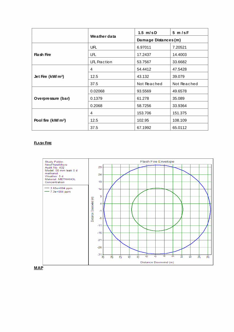
37.5 67.1992 65.0112 FLASH FIRE
MAP

Aqua pharm Exhibit-2_Plant Layout
Models
73000 ppm
36500 ppm
Concentration at Time: 2681 s
Weather: 5 d
Study Folder: New PhastMicro
Model: 50 mm leak 5 d methanol
Material: METHANOL
Height: 0 m
Averaging Time: Toxic(600 s)
Audit No: 432
Cloud Footprint
Jet Fire
Graph

Aqua pharm Exhibit-2_Plant Layout
Models
Effect Zone @ 12.5 kW/m2
Effect Zone @ 4 kW/m2
Radiation Level
Weather: 5 d
Study Folder: New PhastMicro
Model: 50 mm leak 5 d methanol
Material: METHANOL
Audit No: 432
Intensity Radii for Jet Fire
Aqua pharm Exhibit-2_Plant Layout
Models
Weather: 5 D 50 mm leak
Study Folder: New PhastMicro
Model: 50 mm leak
Material: AMMONIA
Height: 0 m
Averaging Time: Toxic(600 s)
Audit No: 516
Cloud Footprint
MAP
Maximum Consentration
GRAPH

Aqua pharm Exhibit-2_Plant Layout
Models
73000 ppm
36500 ppm
Concentration
Weather: 5 d
Study Folder: New PhastMicro
Model: 50 mm leak 5 d methanol
Material: METHANOL
Height: 0 m
Averaging Time: Toxic(600 s)
Audit No: 432
Max Concentration
MAP
Ammonia leakage GRAPH

Aqua pharm Exhibit-2_Plant Layout
Models
Weather: 5 D 50 mm leak
Study Folder: New PhastMicro
Model: 50 mm leak
Material: AMMONIA
Height: 0 m
Averaging Time: Toxic(600 s)
Audit No: 516
Cloud Footprint
MAP
JET FIRE
GRAPH

MAP
Aqua pharm Exhibit-2_Plant Layout
Models
Effect Zone @ 4 kW/m2
Radiation Level
Weather: 5 D 50 mm leak
Study Folder: New PhastMicro
Model: 50 mm leak
Material: AMMONIA
Audit No: 516
Intensity Radii for Jet Fire

Aqua pharm Exhibit-2_Plant Layout
Models
Weather: 5 D 50 mm leak
Study Folder: New PhastMicro
Model: 50 mm leak
Material: AMMONIA
Height: 0 m
Averaging Time: Toxic(600 s)
Audit No: 516
Max Concentration
MAXIMUM CONSENTRATION
GRAPH
MAP

Aqua pharm Exhibit-2_Plant Layout
Models
360000 ppm
73000 ppm
36500 ppm
Concentration at Time: 3464 s
Weather: 1.5 f
Study Folder: New PhastMicro
Model: 50 mm leak 1.5 f
Material: METHANOL
Height: 0 m
Averaging Time: Toxic(600 s)
Audit No: 230
Cloud Footprint
1.5 F m/s D
GRAPH
MAP 1.5 F Jet Fire

Aqua pharm Exhibit-2_Plant Layout
Models
Effect Zone @ 12.5 kW/m2
Effect Zone @ 4 kW/m2
Radiation Level
Weather: 1.5 f
Study Folder: New PhastMicro
Model: 50 mm leak 1.5 f
Material: METHANOL
Audit No: 230
Intensity Radii for Jet Fire
GRAPH
MAP

Aqua pharm Exhibit-2_Plant Layout
Models
160000 ppm
80000 ppm
Concentration
Weather: 1.5 d
Study Folder: ammonia 1.5 result
Model: 50 mm leak
Material: AMMONIA
Audit No: 372
Flash Fire
Flash Fire –
GRAPH
MAP
6.10 MITIGATION MEASURES

Measures and recommendations for the proposed Tank Farm area are as follows:-
Offsite precaution measures are to be prepared.
Adherence of international engineering standards in the Design, Construction and
testing of the storage tanks, equipments and other hardware.
All tanks to be provided with automatic sprinkler system interlinked with fusible
bulbs, the sprinkler system to confirm to TAC design guidelines.
All storage tanks to have level indicators, flame arrestors, breather valves and
foam injection system wherever required.
The pumps used for transferring the solvents shall be not in the main dyke but in a
separate dyke.
All pumps used to have mechanical seal to prevent leakages and fugitive
emission.
Spillages and leaks from the storage tanks can be collected and transferred out
and treated for safe disposal.
Storage areas shall be free from accumulation of materials.
All electrical and instrumentation equipment used in the tank farm area to be
rated for the solvent present as per ATEX standards.
There should be good communication system available near tank farm area to
the control room, and it should be flameproof.
The tank farm should be protected with upwind and downwind foam monitors, the
spacing of the same is to be as per TAC standards.
A good layout should provide for adequate fire fighting access, means of escape
in case of fire and also segregation of facilities so that adjacent facilities are not
endangered during a fire.
Routine Inspection of Flame arrestor and breathing valve should be done.
At every tank farm its license number, storage capacity & name of the chemicals
should be displayed at the entrance.
Flameproof Motors for unloading near flammable storage tank should be provided
with double earthing.
All electric fittings used in the tank farm should be flame proof type.
Condition of N2 blanketing should be checked regularly, if provided.
Fire protection system shall be provided on each tank, a fixed foam pouring
arrangement to tackle any duke spillages should also be considered. The foam
blanket prevents surface evaporation form liquid pool.
Develop detailed maintenance/contractor procedures requiring physical
identification of tank vents during walk-through and other devices which haven’t
cover during maintenance activities.
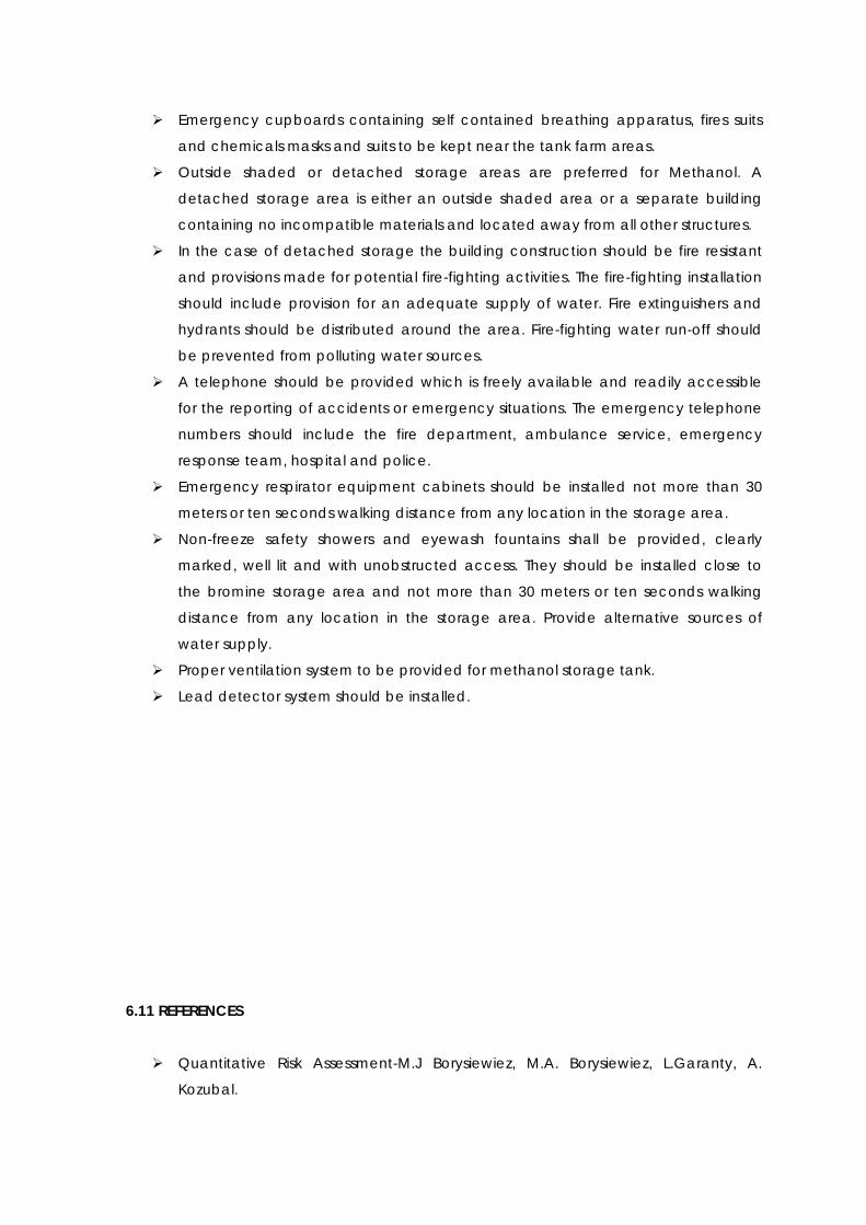
Emergency cupboards containing self contained breathing apparatus, fires suits
and chemicals masks and suits to be kept near the tank farm areas.
Outside shaded or detached storage areas are preferred for Methanol. A
detached storage area is either an outside shaded area or a separate building
containing no incompatible materials and located away from all other structures.
In the case of detached storage the building construction should be fire resistant
and provisions made for potential fire-fighting activities. The fire-fighting installation
should include provision for an adequate supply of water. Fire extinguishers and
hydrants should be distributed around the area. Fire-fighting water run-off should
be prevented from polluting water sources.
A telephone should be provided which is freely available and readily accessible
for the reporting of accidents or emergency situations. The emergency telephone
numbers should include the fire department, ambulance service, emergency
response team, hospital and police.
Emergency respirator equipment cabinets should be installed not more than 30
meters or ten seconds walking distance from any location in the storage area.
Non-freeze safety showers and eyewash fountains shall be provided, clearly
marked, well lit and with unobstructed access. They should be installed close to
the bromine storage area and not more than 30 meters or ten seconds walking
distance from any location in the storage area. Provide alternative sources of
water supply.
Proper ventilation system to be provided for methanol storage tank.
Lead detector system should be installed.
6.11 REFERENCES
Quantitative Risk Assessment-M.J Borysiewiez, M.A. Borysiewiez, L.Garanty, A.
Kozubal.

Guide to Manufacture, Storage and Import of Hazardous Chemicals Rules
(MSIHC), 1989 issued by the ministry of environment and forests, (MoEF) Govt.of
India as amended up to date.
World Bank Technical papers relating to “Techniques for assessing Industrial
Hazards”.
Major Hazard Control by ILO.
Risk Management Program guidelines by EPA (US).
World Bank Technical Paper no. 55 – Technica ltd. For assessing hazards – A
Manual.
PHAST v 6.53-Software.
Overall plot plan.

6.12 APPENDIX: ASSUMPTIONS AND RULE SETS
TOPIC: Process Material Characterization
APPLICABILITY: Consequence Analysis
DATA / RULE SET: ASSUMPTIONS:
The flow, densities, temperatures and
pressured of the streams are taken directly
from Heat & Mass Balances supplied for the
Project.
Multi-component process streams have
been simplified for release consequences
purposes. This is achieved by modeling them
as a single stream based on review of molar
fraction stream compositions and taking the
most representative stream.
It is assumed that the simplification of multi-
component process streams will not affect
the results. The most representative stream
is considered based on the stream that has
a potential to cause maximum harm, the
effect is likely to be more conservative.
LIKELY EFFECT ON
RESULT:
The simplification of multi-component process streams is likely to affect the consequence
analysis results such as dispersion, radiation and explosion. The results are likely to be more
conservative thus exaggerating the risk slightly.
REFERENCE:
Heat and Material Balance
REVISION RECORD
REVISION NO. DATE: DESCRIPTION: CHECKED: APPROVED:
0 Draft for Client
review
TOPIC: Leak Sizes
APPLICABILITY: Consequence Analysis
DATA / RULE SET: ASSUMPTIONS:
Leak sizes are defined in terms of diameters
of nominally circular holes.
Although real holes in process equipment
are unlikely to be circular, the release rate
depends on the hole area and is largely
independent of the hole shape.
LIKELY EFFECT ON
RESULT:
The hole sizes will affect the release rate, dispersion, jet fire, pool fire and other
consequence analysis results.
REFERENCE:

CMPT – DNV Technica
REVISION RECORD
REVISION NO. DATE: DESCRIPTION: CHECKED: APPROVED:
0 Draft for Client
review
TOPIC: Release, Isolation
APPLICABILITY: Consequence Analysis
DATA / RULE SET: ASSUMPTIONS:
For releases, the quantities available for
release are taken as the total isolatable
inventory within each section of plant. This
assumes that a release occurs at the lowest
point of each section.
This approach is conservative for low
pressure systems because loss of
containment events may occur at
elevations above the lowest point hence
limiting the quantity of liquid available for
release.
Considering the lowest point of release also
covers release of gas.
Operating inventory is considered to be
10% below the Level Safety High (LSH) level
of the equipment.
For cases where isolation fails, adjacent
section inventories are added to the
release. This will therefore increase the
quantity of material released and duration
of release.
Isolation is assumed to be provided by ESD
valves of any other valves connected to
ESD system.
Isolation is assumed to automatically take
place after confirmed fire detection (by
hydrogen detector detectors / manual).
The total isolation time is assumed to be a
function of detection time, response time
and shutdown time (isolation time =
detection time + response time + shutdown
time).
The isolation time is assumed to be 5 min,
considering the time required for ignition
(delayed ignition time considered for
conservative results), response time
(automatic / manual whichever is greater)
and ESD valve shutdown time.
LIKELY EFFECT ON
RESULT:

6.13 CONCLUSION
The latest version of the renowned PHAST Risk software package of DNV is used for
carrying out the risk analysis.
Following are some of these references adopted for the study:
Guide to Manufacture, Storage and Import of Hazardous Chemicals Rules
(MSIHC), 1989 issued by the Ministry of Environment and Forests (MoEF), Govt. of
India as amended up to date.
World Bank Technical papers relating to “Techniques for assessing Industrial
Hazards”.
“Major Hazard Control” by ILO.
Risk Management Program guidelines by EPA (US).
The scenario (Catastrophic rupture) is based on large-scale release of material stored in
the tank and the use of worst stability class, though this may not always happen. We have
assumed catastrophic rupture for all the tanks as per the guidelines suggested by DNV –
UK. Similarly, maximum inventory in the tank at the time of failure is assumed.
The above assumptions are likely to affect the release rate, dispersion, jet fire, pool fire
and other consequence analysis results.
REFERENCE:
CMPT – DNV Technica
API 521
REVISION RECORD
REVISION NO. DATE: DESCRIPTION: CHECKED: APPROVED:
0 Draft for Client
review

DISASTER MANAGEMENT PLAN
7.0 OBJECTIVE
The objective of the plan is to down steps to handle emergency situation that may arise due to
leakage/spillage, explosion and fire of the various chemicals, fuels in the plant and any adverse
effect on employees and public at large is minimized and normalcy is restored within shortest
possible time.
This Disaster Management Plan is prepared to meet such grave emergency which can occur
due to big fire in the plant missile hit due to air raid, heavy leakage of flammable liquid or gas or
explosion (internal or external cause) in any plant.
Emergency Response Plan (action plan) has been drawn to fix responsibility & actions to be
taken by various groups to meet & contain the emergency within shortest possible time & with
minimum loss to men, materials, machines & property. It is responsibility of all individuals in their
respective areas to ensure success of this plan. This plan will be circulated for benefit / training of
all individuals working in M/s. Aquapharm Chemicals Pvt. Ltd., Plot no K-3/1,2,3 MIDC Mahad ,
District – Raigadh.
The major functions & objectives to formulate the plan are:
(I.) To mobilize the available / trained manpower and handle the emergency from:
On-site (within factory)
Off-site (through outside agencies).
(II.) To ascertain urgently likely area of influence and take actions for warnings, control of
disaster with minimum damage to men, material, machines and evacuation of employees /
public, identify the persons affected / dead, arrange first aid / medical help to the victims.
(III.) Inform relatives of the casualties provide authoritative information to News Media & others;
preserve relevant records & equipments needed as evidence in any subsequent inquiry.
(IV.) Appraise District Administration / Civil authorities etc. order to ensure prompt relief for
execution of Emergency Response Plan.

This document sets out the emergency plans for all levels of accident ranging from a local
incident within the site boundary to a situation that requires outside support. The objectives of
the emergency plan are:
To protect lives of working personnel and nearby population.
To contain the hazards and to control their spread.
To minimize the impact on the environment.
To minimize the loss to plant and production.
7.1 DEFINITION AND SCOPE
A major emergency is defined as one, which may affect one or several sections of the plant and
possibly extend beyond the factory boundaries. It may cause serious injuries, loss of life or
extensive damage to property. The potential hazards may be due to following:
Spillage / Leakage of solvents.
Leakage or Toxic Release of Gas.
Fire or explosion in the plant or storage area.
The Disaster Management Plan has been prepared in order to provide proper guidance to plant
operating personnel to confidently handle any accidental leakage / spillage of the solvents or
fire / explosion / bursting of vessel or any natural calamity or sabotage. With this objective
comprehensive information has been assembled in the following pares on the solvents, fuel oil
and chemicals used (Hazardous) about its properties, fire hazards, safety appliances, safety
measures incorporated in the plant, emergency procedures and finally regarding the
constitution & responsibility of Emergency Rescue Team (Emergency Response & Management
Team / Task Force).

7.2 METHODOLOGY
A major emergency occurring at a plant is one that may cause serious injuries, loss of life,
extensive damage to property or environment or serious disruption inside or outside the plants.
This may demand the rescue and relief measures on a war footing to handle it effectively and
quickly. Within the high-risk technology industries, the need for well-planned measures should be
self-evident.
No matter how well a process is controlled and safeguarded by instruments and process safety
procedures, it is inevitable that there is a residual risk, which is capable of causing a variety of
emergencies.
The Factories Act, 1948 as amended in the year 1987 under section 41B requires that every
occupier shall draw up a Disaster Management Plan and detailed disaster control measures for
his plant and make them know to the employees and to the general public living in the vicinity
of the plant. According to GFR, it is statutory for the industries to submit Disaster Management
Plan with relevant details.
Its objective is to reduce the severity of loss following particular hazardous incidents. At the same
time, must be clearly understood that it is not a substitute for maintaining good standards for
working consistence with the requirements of safety and health inside the plants.
7.3 INTRODUCTION
The Disaster Management Plan describes the Organization & procedures for dealing with
potential accidents arising from the operations of M/s. Aquapharm Chemicals Pvt. Ltd., Plot no
K-3/1,2,3, Additional MIDC Mahad, District –Raigadh.
Experience of accidents that have occurred in various other chemicals manufacturing plants
was considered in the preparation of this Plan especially storing & handling the hazardous
chemicals identical to this plant. This plan will need periodic review & modification following
emergency exercise, or include any new information relating to changes to the facilities. List of
Final Products were given in Chapters in 2.
The workforce inside the plant will be exposed to various systems, pipelines & vessels and process
equipments which, if not properly operated & maintained could cause serious accidents
affecting life & properties in the vicinity of accident site. In addition to these, the inventory and

transportation of the chemicals may create chance of accidents. This Plan is needed to respond
to a variety of emergencies / disasters:
I) Disasters due to emergency on account of:
Fire
Bursting or Explosion
Oil spillage
Spillage or leakage of toxic materials
Electrocution.
II) Disaster due to natural calamities such as:
Flood
Earth quake
Storm / cyclone
Cloud burst / lightening
III) Disaster due to external factors such as:
Food poisoning / water poisoning
Sabotage
Civil Riots or War
Terrorism, air raid, etc.
The action plan responding to an emergency situation depends very much on the level of the
emergency which, itself is defined by the consequences arising from the types of hazard
identified. The organization & duties of the Emergency Team & the action plans for each of the
disaster levels is included in this document.
The plant will be provided with various safety & disaster control facilities to prevent & control any
disastrous occurrences. Measures for preventing & controlling disaster are outlined in following
sections. It also includes information on the plant facilities & its location.
This Disaster Management Plan describes the organization and procedures for dealing with
potential accidents arising from the operations.

This plan will need periodic review in case of modification following emergency exercises, or to
include any new information relating to changes to the plant facilities.
7.4 DETAILS ABOUT SITE:
M/s. Aquapharm Chemicals Pvt. Ltd. Plot No K-3/1,K-3/2,K-3/3, Additional MIDC Mahad District
– Raigadh .Maharashtra.
7.5 PLANT LAYOUT AND DETAILS (Refer Annexure-1)
STORAGE AREA
Major storage tanks will be above ground, located safe distance away from the plant and the
storage tanks will be under strict safety conditions. The storage tanks include Methanol,
Ammonia (Liquid), Acetic acid and Amines.
UTILITY
The Utility block encloses Air Compressor, Boiler and DG Set for Emergency Backup set etc.
ETP
The ETP consisting of Equalization Tank & all rest primary and secondary treatment units will be
installed.
7.6 EMERGENCY ORGANIZATION
This chapter is devised to suggest the organization for emergency preparedness. Key personnel
to combat emergency are nominated with specific responsibilities according to set procedures
and making best use of the resources available and to avoid confusion. Such key personnel
include Chief Emergency Controller, Site controller, other key personnel such as First Aiders, Fire
fighting staff, support staff and communication staff, advisory staff.
All such key personnel (Annexure – 2) shall be available in all the office timings and shall be
called during emergency in holidays.

ROLE OF KEY PERSONNEL
7.6.1 Chief Emergency Controller
He has overall responsibility for direction operation and calling outside help for emergency
control center. As he is required to take decisions by collaboration between all processes heads,
the factory manager (Leader- Conversion Processes) of the Aquapharm chemicals Pvt. Ltd.
shall act as the Chief Emergency Controller.
The duties and responsibilities of Chief Emergency Controller are as follow. Being aware of the
emergency immediately he will go to the emergency control room. (Security cabin)
I. Over all in-charge of the situation and takes responsibility for overall control.
II. Decide whether a major emergency exist and on declaration of a major emergency in
consultation with the Site Controller. Ensure that the outside emergency services and
mutual help are called, the off-site plan gets activated and if necessary, nearby factories
and population are informed. Inform about the situation to other manufacturing
locations.
III. Ensure that the key personnel are called in.
IV. Exercise direct operational control of those parts of the works outside the affected area.
Continually review and assess possible developments to determine the most probable
course of events.
V. If necessary, direct for evacuation of neighboring population.
VI. Ensure that casualties are receiving adequate attention. Arrange for hospitalization of
victims and additional help if required. Ensure that the relatives are communicated.
VII. Inform and liaise with the Chief Officers of the Fire and Police Services, District Emergency
Authority and with the Factory Inspectorate and experts on health and safety. Provide
advice on possible effects on areas outside the factory.

VIII. In the case of prolonged emergencies involving risk to outside areas by wind blown
materials, contact the local Meteorological Office to receive early notification of
impending changes in weather conditions.
IX. Review the authorized statements prepared for the news media.
X. Direct for the preservation of evidence.
XI. Control rehabilitation of affected areas and victims on cessation of the emergency. Do
not restart the research activities unless it is ensured safe to start and cleared by the
authorities.
7.6.2 SITE CONTROLLER
A. His primary duty is to take charge at the site of the incident. In the initial stages he will take
decisions involving the operation of the other plants or to stop or continue any process and take
decisions to control the incident.
Site- SHE representative may be appointed as Site Controller for all the 24 hours of working and
holidays. Shift supervisor will be appointed as Alternative (Deputy) Site Controller and would take
the charge in the absence of the Site controller. In case the emergency occurs at more than
one place the alternative site controller would take charge as Site Controller in their respective
places/ areas to prevent the danger of a disaster.
He will proceed to the scene immediately on being aware of the emergency and its
location.
Assess the scale of emergency and decide whether a major emergency exists or is likely.
On his decision, he will activate the on-site plan and if necessary the off-site emergency
plan.
B. Assume the duties of the Chief Emergency Controller till his arrival. For this purpose he will
depute his alternative (deputy) Site controller at the site of scene and he will go to the control
center.
Direct and evacuation of all personal likely to be affected by the emergency.
Ensure that the outside emergency services, including mutual aid, have been called in if
necessary.

Ensure that key personnel have been called in.
C. Direct all processes/ functions within the affected areas with the following priorities.
Secure the safety of personnel.
Minimize damage to property and the environment.
D. Direct rescue and fire fighting operations until the arrival of the outside Fire Brigade, when he
will relinquish control to the Head of the Fire Brigade.
E. Search for casualties.
F. Evacuate non-essential workers to the assembly points.
G. Set up a communications point and establish telephone / messenger contact as appropriate
with the emergency control center.
H. Give advice and information as requested to the Head of Safety & Fire and other emergency
services.
I. Brief the main Incident Controller and keep informed of developments.
J. Preserve evidences that will be necessary for subsequent inquiry into the cause of the
emergency and concluding preventive measures.
7.6.3 TEAM – A (FIRE FIGHTING STAFF – PLANT OPERATOR)
These task forces known as Fire fighting staffs will be trained to handle various fire fighting
equipments during emergency situations. They shall report to the Site controller for fire
extinguishing related task.
First Aid team shall rush to the incident spot and get the feedback from the Site
controller.
The team determines the origin and causes of fires. They collect evidence, interview
witnesses and decide the plan.
Select correct fire extinguisher for fire fighting.

Fighting fire/ gas leak and spill control till fire brigade takes the charge.
To help to the fire brigade and mutual aid terms if it is so required.
7.6.4 TEAM – B (SUPPORT TEAM – MAINTENANCE OPERATOR)
This task force known as Support team will help the personal during emergency situations. The
roles and responsibilities of the team are:
Direct the personal to go to the Emergency assembly points.
Search, Evacuation, rescue and welfare.
Planning of assembly points to record the arrival of evacuated personnel. Planning for
outside shelters and welfare of evacuated persons there.
Assistance of causalities reception areas to record details of causalities.
Moving cars or other vehicles away from areas of risk or from the scene of the incident.
To have a head count of personal at both the assembly point and tally with the total
persons at the time of the emergency.
7.6.5 TEAM – C (TRAINED FIRST AIDER)
This task force known as First Aid staffs are trained for emergency handling shall be available all
the times in duty hours to assist the personal during emergency. They shall report to the Site
controller for first aid related task details in corporate in onsite Emergency plan approved by
Plant Manager.
First Aid team shall rush to the assembly point and get the feedback from the Site
controller about the emergency
As per the instruction, they rush to the area of emergency and assess the situation.
Diagnoses the situation and decides whether the causality shall be moved to the safe
area.
The injured personal are moved to the safe place and give first aid as required by the
situation.
Move / transport the causalities to the ambulance / nearby medical center for
necessary medical assistance.
7.6.6 TEAM-D (COMMUNICATION TEAM)

This task force known as Communication team will help the personal and organization. This task
force known as Communication team helps the personal and organization during emergency
situations. The roles and responsibilities of the team are:
Inform all the employees about the emergency and ask them to come to the assembly
point.
Asking for the ambulance / fire brigade as directed by the Chief Emergency Controller.
Informing surrounding factories and the public as directed by the site main controller.
Planning of works entrances in liaise with the police to direct emergency vehicles
entering the work, to control traffic leaving the work and to turn away or make
alternative safe arrangements for visitors, contractors and other traffic arriving at the
works.
Assistance at communications centers to handle out going and incoming calls and to
act as messengers if necessary.
7.7 TEAM-E-ADVISORY TEAM (QA PERSONNEL)
This task force known as Advisory team helps the personal and organization during emergency
situations. The roles and responsibilities of the team will be:
Assist chief controller or site controller in their work.
Guide site controller to take emergency shout down in case of emergency.
Guide rescue team to first Aid by referring MSDS.
Guide fire fighting team to used correct fire extinguisher to extinguish fire.
7.8 EMERGENCY CONTROL CENTRE (ECC)
The centralized emergency control center will be situated at the security cabin near the main
gate from which the operation to handle the emergency are directed and coordinated. The
center will be equipped to receive and transmit information and directions from and to the
incident controller and areas of the works as well as outside.
The emergency contact numbers for the mutual aids like nearest police station, fire station,
hospital, ambulance service etc. will be displayed at the required location along with
emergency control centre and security gate.

7.8.1 Emergency Control Centre Will Contain the Following Facilities:
a. Adequate number of external telephones
b. Adequate number of internal telephones.
c. Plans of the location
d. Stationeries
e. Copies of this on-site and off-site emergency plans.
Trained personnel will always be available in these areas who can rush to the emergency point
in shortest time. Warning system will always be kept in working order.
Fire extinguishers of suitable types and hydrants will be provided at almost all the places of plant.
7.9 MEDICAL ARRANGEMENTS
First Aid boxes & first-aider list will be kept at security cabin. In case of any medical assistance
other than first aid, the Admin in charge/ Site- SHE representative arrange for a vehicle to shift
the casualty to the below mentioned hospital, or call an ambulance to mobilize the casualty to
the medical center.
7.10 TRANSPORT AND EVACUATION ARRANGEMENTS
In a major emergency, it will be necessary to evacuate personnel from affected areas and to
further evacuate non-essential workers from areas likely to be affected should the emergency
escalate.
A common siren (wailing) will be provided for the evacuation of people. On hearing the siren,
people will disperse from the work area. Proper instruction will be given to all the employees
about the rising of siren and the emergencies.
The employees would proceed to the predetermined assembly points on hearing the siren and
the support staff / security forces would be instructed to divert the people away from the
affected area and towards the assembly points.

7.11 OUTSIDE ORGANIZATIONS IF INVOLVED IN ASSISTING DURING DISASTER
Type of Accidents: Major Accidents, which may require outside help are follows:-
Leaks/Spillage of: Solvents, Chemicals.
Bursting at: Process area and Storage area.
Fire or Explosion at: Reactors, Storage tanks, Utilities and Transformer / Substation.
7.12 OUTSIDE HELP
Fire brigade of the nearest area shall help the plant fire control team during fire at site.
Police station personnel & DSP shall help the company to maintain law & order, Traffic
control & evacuation operations.
Nearest Hospital or Nursing home shall render emergency medical services to the
company for the first aid & medical treatment during emergency.
District supply officer shall ensure continuous supply of essential items, medicines (Govt.
Quota) and other emergency materials during emergency.
7.13 INFORMATION ON RISK EVALUATION PRELIMINARY HAZARD ANALYSIS
Following types of hazards exists in the factory as:-
Storage Hazard (Solvents)
Material Handling
Operating Hazards (Process)
External Hazards
7.14 HAZARDS/FORESEEABLE SCENARIOS
Though it will be an impractical to describe all the foreseeable scenarios involving hazardous
chemicals and the suggested action for the same, some important ones are discussed here
briefly. Even in identical incidents the right course of action may not necessarily be the same
every time as the actual action will depend on the several factors, such as the place of incident,
quantity of chemical involved, the amount of release, the nature of chemical, the wind
direction, the wind velocity, temperature of surrounding, time of day, prevailing season and
weather condition.

A) In case of failure of Ammonia storage tank:
Following are the general guideline for emergency action.
Raise the alarm
Start the fire monitor and adjust the flow rate of water over the leak point.
Declare the emergency and follow the role & responsibility.
Check the wind direction, decide the assembly point.
One of security should collect all the visitors & contract labors to the assembly point.
Inform to the all surrounding unit & near by unit.
Assess the leak situation & confirm the location of leak.
Arrange SCBA, spark proof tool, other required PPE’s with the help of supporting team B.
Try to attend the leak of the proper PPE’s and with the help of advisory team & incident
team.
Take head count at site and inform to the chief controller.
Also take head count at the assembly point and tally.
Search for missing person if any.
Give first aid to the person who need it and check for further treatment or hospitalization
required.
Confirm the massage of incident attend to the main controller & raise the all clear siren.
Collect the photograph and other evidence to cause fine.
B) In case of Fire to the Flammable Liquid / Solvents:
In case of declaration of onsite emergency (Hearing of emergency siren), evacuate the area as
per evacuation plan & exit signs on instruction of shift in-charge / incident controller as quickly as
possible after safe shutdown of the plant. See that the wind direction is in opposite direction of
assembly point by wind direction indicator. If not, change the assembly point.
Following are the general guideline for emergency action.
Raise the alarm through nearest MCP
Inform security and shift in charge.
Carry nearest fire extinguisher & try to extinguish if possible.
Assemble emergency team and inform other emergency members.
Check the wind direction, then decide the assembly point and inform accordingly.

Warn the people nearby.
Attempt to isolate /extinguish the fire with the help of others with available appropriate
extinguishers.
Arrange fire hydrant hose and try to cool surrounding
Cordon the area and try to shift the drum of flammable material.
Used foam generating nozzle and create foam to extinguish fire.
If fire beyond control call fire brigade after consultation with chief controller.
Cool the surrounding or remove flammable material if possible.
Take head count at site and inform to the chief controller.
Also take head count at the assembly point and tally.
Search for missing person if any.
Call for mutual aid members for help, if require.
Arrange for rescue, if required.
Give first aid to the injured person and check for further treatment is required.
Give priority to saving life and preventing further injuries.
Confirm the massage of incident attend to the main controller & raise the all clear siren.
Collect the photograph and other evidence to cause fine.
C) In Case of release of Solvents/Chemicals from Tankers/Tanks inside the factory premises:
This area is focused on PCL3 & Ammonia, Acetic acid , Calcium Chloride & are stored at plant
site. Special instruments for storing, Handling & emergency actions in case of release of toxic &
flammable material are given separately in MSDS.
Following are the general guideline for emergency action:
Use PPE’s like SCBA/Gas mask/Respirator & evacuate the area.
If possible shift the tanker from storage area to parking area (due to limited space
availability elsewhere).
In case of declaration of onsite emergency (Hearing of emergency siren), evacuate the area as
per evacuation plan & exit signs on instruction of shift in-charge / incident Controller as quickly
as possible after safe shut down of the plant. See that the wind direction is in opposite direction
of assembly point by wind direction indicator. If not, change the assembly point.
D) In case of Flood / Earthquake:

In case of natural calamity like flood, Strom or earth quake (remote possibility) or war like
situation the management may seek outside help. The help may be for fire fighting, Evacuation
(of surrounding population), Medical treatment, shelter, food, transport or communications.
The responsibilities of outside organization will be to render services as follows during emergency.
Following are the general guideline for emergency action:
Close main valve
In case the cylinders are on the ground the same be shifted to storage shed to ensure
that the floodwater shall not carry the cylinders.
Switch off electricity (main).
Assemble outside the office, away from Electric Poles & Wires.
Evacuate the areas after initiating (communication in working condition) off site
organization.
E) In case of War/Civil riots:
Following are the general guideline for emergency action:
Intimate nearest police station & stimulate off site emergency plan
Stop unloading / loading operations (if any)
Intimate civil defense dept. about the situation
Security persons shall protect & control law & order.

F) Solvents Storage & handling:
Following are the general guideline for emergency action:-
All storage tanks will be equipped with contact DP/non-contact radar type level
transmitters with feedback to main PLC/SCADA.
All storage tanks will be equipped with level switch which will stop the respective transfer
pump on activation at high level.
Local temperature and pressure gauges will be provided wherever applicable.
Leakage or spillage of this solvent may lead to health hazards or fire / Explosion or toxic
release.
7.15 POWER SUPPLY INTERRUPTION
In case of major electrical system failure, DG set will be provided for emergency plant
operations and emergency lighting in the premises.
7.16 HAZARD IDENTIFICATION AND RISK SUMMARY
7.16.1 Major Hazards
A brief description of the possible hazards in handling hazardous materials is given in this section.
1) Leakage & Spillage of:
Caustic lye,
Methyle alcohol
Ammonia
Acetic Acid

2) Fire & Explosion of:
Compressor
Solvents Storage
Flash Fire
Panel(Electrical)
Pool Evaporation:
If the fluid, which escapes from the containment, is a liquid, then vaporization must occur before
a vapor cloud is formed. The rate at which vaporization takes place determines the formation of
such a vapor cloud.
7.17 SAFETY AND MITIGATING MEASURES
7.17.1 Safety Considerations in the Design
Safety Considerations in the design is an important mitigating measure, will be provided to
contain and control the emergency are outlined below:-
7.17.1.1 General safety considerations:
Adherence of international engineering standards in the design, Construction and testing
of the storage tanks, equipments and other hardware.
Statutory approvals of hazardous storage, waste treatment and disposal stack emission
etc.
Storage tanks containing hazardous materials will be located away from the plant.
Full fledge fire protection system.

7.17.1.2 Equipments and Process safety:
All Storage tanks will be located in Dykes and equipped with high and low level indicator
wherever indicated.
Spillages and leaks from the storage tanks can be collected and transferred out and
treated for safe disposal.
Storage tank containing hazardous storage will be located away from the main plant.
All tanks will be protected against overpressure by pressure relief valve
Floor washing will be collected and treated in effluent treatment plant.
Fugitive emissions will be prevented by providing single mechanical seal for pumps.
All storage tanks will be equipped with contact DP/non-contact radar type level
transmitters with feedback to main PLC/SCADA
All storage tanks will be equipped with level switch which will stop the respective transfer
pump on activation at high level.
Local temperature and pressure gauges will be provided wherever applicable.
The hazardous reactors are provided with seal arrangements, which will prevent leakage
of fugitive emission in case of seal failure.
7.17.1.3 Safety measures for Ammonia storage:
Vapor pressure of aqua ammonia is about equal to the atmospheric pressure, it shall be
stored in closed containers.
The storage area should be dry and cool. If housed in a closed building, ventilation
should be provided; either natural or mechanical. Avoid pocketing of ammonia vapor
under floors, roofs or similar structures.
Ammonia vapor will burn when mixed in air at concentrations between 15% - 28%. Sparks
or ignition sources must be excluded wherever concentrations in this range could exist.
The installation of a foam system will reduce significantly the toxic effects in case of any
significant leakage in the ammonia storage area.
Coordinate and exercise emergency plan together with neighboring companies e.g.,
“neighbors to stay inside the buildings in case of alarm after a major ammonia leak”.
Firefighters shall be aware of the possibility of flash fires and should take adequate
precautions.
7.17.1.4 Safety measures for Methyl Alcohol storage:
Methanol is a highly flammable, toxic substance, so extreme caution should be exercised
during storage and dispensing operations.
When storing methanol, proper precautions should be taken to ensure the safety and
efficacy of the methanol as well as the safety of the surrounding area.
Methanol shall be stored in a cool, dry place away from direct sunlight and moisture.
To minimize the risk of fire, fully enclose storage tanks in a dike or some other secondary
containment system, and do not store methanol near oxidizing compounds such as:
Perchlorates, Bromine, Chlorine, Hydrogen peroxide.
Methanol can cause corrosion to some metals and plastics. Prior to storage, it must be
ensured that the storage tanks or containers being used are constructed of the correct
material with no traces of unacceptable materials.
Methanol is a substance that must be taken very seriously. Proper storage procedures
and precautions should be observed at all times to prevent health problems, loss of life,
fire, explosion, and environmental contamination.
The methanol storage tank shall be installed with a flame arrester.
Methanol burns with a clean clear flame that is almost invisible in daylight. Stay upwind!
Isolate and restrict area access.
Use fine water spray or fog to control fire spread and cool adjacent structures or
containers.

7.17.2 Fire Protection and Fire Fighting System
The plant will be equipped with a comprehensive fire protection system. Following facilities will
be provided for the fire protection:-
Fire Water Supply
Fire Hydrant system, Fire sprinkler system with smoke/fire detectors
Portable Fire Extinguishers
7.18 OTHER AREAS OF HAZARDS AND CONTROL
7.18.1 Water Drainage
In order to avoid difficulties of storm water distribution proper drainage to the storm water/rain
water runoff system will be designed so as to protect the plant equipments, Building & offices. No
area will submerge in the flood as adequate height has been provided to all installations such as
utility block, office building, Process plant, warehouses & storage area has been provided with
individual dyke.
7.18.2 Electrical Supply
As the fire protection system is safety related, it is mandatory that any electrical power supply for
the control, Operation or instrumentation of the system shall be from an assured supply. During
monsoon season the electrical circuit (conduit wiring) sometimes comes in contact with wet or
structure (in case of any breakage, loose fittings), in such case there is probability of current
leakage.
7.18.3 Fire or Bursting of Tanker
In case any vehicle/tanker/truck catches fire or burst/explodes on the road or similar events
occurs inside the plant area during unloading of materials, the impact of such event shall have
on the entire plant. Smoke cloud, fire, considerable heat radiation will take place apart from
destabilizing civil & mechanical structures.
7.18.4 Leak/ Spillage of Toxic Liquid on Road

In case of spillage or leakage of liquid on the road, the same affect the employees. In such case
fire fighting system shall be kept ready near reception as well as the employees may be asked
to assemble at backyard of the plant as the front area shall be directly exposed to such release.
After clearing the emergency, the employees could be asked to absorb/neutralize the toxic
chemicals by suitable absorbent/neutralizers.
7.18.5 Storage Hazards and Control
Storage facility will be situated away from the manufacturing plants and fulfilling all the rules and
regulations, all storage tanks of hazardous substances will be located within the boundary wall,
constant watch by security & plant personnel round the clock.
As prescribed in the relevant regulation, the entire electrical fittings shall be of fireproof (FLP)
fittings. Proper enclosures in the form of bund walls will be provided for all the storage tanks. All
necessary fire fighting arrangements have been provided near the storage area to combat fire
emergencies. Material Safety Data Sheets (MSDS) for all the raw materials, intermediates and
final products will be prepared and attached. WI for loading & handling of chemicals will
properly be displayed in English & Local language near the area. Details of Raw Materials
consumption and storage were given in Annexure - 5.
7.18.6 Process Hazards
In this section Plant- wise hazards of processes, operations and controls provided to cope up
with all kinds of abnormalities. The details regarding various controls like exhausts, scrubber, vents
and other operating control etc. have been mentioned.
The consequences arising from the release of a toxic material would be time dependent and
would vary according to the point of release. The major difference between release of toxic
and flammable materials is that toxic clouds and therefore may remain hazardous over greater
distance.
Scrubbers for control of Vapor / Non-Condensable gases & fines from dryer units will be installed
in the plant.

7.18.7 Trade Waste Disposal
Organization will be more concerned for environment protection and pollution abatement at all
times. In a cohesiveness endeavor irrespective of costs involved, the company has been trying
to reduce and abate pollution to its ultimate end.
The trade effluent streams from all different plants are collected in effluent plant and it is
properly treated by primary, secondary & Tertiary treatment methods.
Provision will be made to dispose Solid wastes. The company will dispose off all solid waste in safe
manner.
7.18.8 Disaster Management
This chapter highlights the Organization for disaster preparedness. No plan will succeed without
effective Disaster Management. Disaster Management Plan is a part and parcel of a good ON-
SITE and OFF-SITE emergency plan, without which all resources, facilities etc., event available
with us, can not be put into services at a right time is the key factor in tackling an emergency.
It is not possible to envisage and detail every action which should be taken in emergency and
to harness the basic elements of emergency preparedness such as Gravity of emergency,
Communication of information, on-site action for process and emergency controls, Mobilization
of internal and external resources for fire and toxicity control etc. Emergency Organization is set
up specifying duties and responsibilities of all to make best use of all resources and to avoid
confusion while tackling the emergency.
Disaster Management Plan / On-Site Emergency Plan highlight the flow of information and co-
operation among various action groups within the factory. Off-site Emergency Plan indicates
various action groups at district levels which will get engaged in case of off-site emergency.
Emergency organization and arrangement include:
Incident Controller
Alternate Incident Controller
Site Main Controller
Emergency Teams
Assembly Points

Emergency Control Centre
Fire & Toxicity control arrangements
Medical arrangements
Transport control arrangements
Pollution control arrangements
Other arrangements.
7.19 HAZARD CONTROL AND EMERGENCY SHUT-DOWN
7.19.1 Spillage Incident Emergency Reporting
Location
Name of material (spilled)
Equipment from which the spillage occurred
Spill control media
7.19.2 Emergency Action in Case of Spillage
Assess the situation and blow siren depending upon the situation.
Stop tower operation if required.
Stop hot jobs in surrounding area; suspend operations which are likely to create sparks.
Check wind direction and approach from upward direction.
Inform effluent treatment plant about the possibility of hydrocarbons coming into the
effluent plant.
Be prepared for fighting if required Start evacuation.
Cool down surrounding equipments / vessels with water.
Vapors traveling in down wind direction should be knocked down with the fire water
spray.
Cordon off the area if needed.
Evacuate non-essential people from the surrounding depending upon the emergency.
Hydrocarbon fire should be fought with foam and DCP
In case of liquid pool, advice fire personnel to cover it with foam.
EMERGENCY ACTION
Check the bund wall valve for its close position.
All personnel handling the emergency should wear PVC suit / alkali suit, gumboot, PVC
hand gloves, PVC goggles.
Isolate the sources of supply.
Cordon off the area.
Avoid the entry of unnecessary people.
Start barricading the spillage area with sand / earth.
Spilled caustic is to be collected in sealable container if possible or divert to effluent
plant, neutralize the same with dil. HCL.
Flush the affected body parts with plenty of water and seek medical help.
7.20 EMERGENCY LIGHTING AND POWER SUPPLY, ISOLATION MAP
For Emergency, Plant Operations and Emergency Lighting provisions will be made according to
requirements. DG set will be provided as backup.
7.21 ALARM AND COMMUNICATION
It is necessary to communicate for (i) Recognizing the emergency, (ii) Raising of the alarm
(Siren), (iii) The declaration of the emergency and (iv) The implementation of the evacuation
plan, if necessary. Therefore effective signals and procedures should be devised to
communicate.
Communication is a critical factor in handling an emergency. To control the situation by the
earliest possible action, the practice should be that any employee can raise an emergency
alarm.
The choice of a suitable alarm system will depend on local circumstances and will be influenced
by size of the plant, type of hazard and the existing alarms system. Essential requirements are
that there should be an adequate number of readily identified points from where the alarm can
be raised and these needs to be clearly indicated by sign boards and by indications in the
plans.
In areas where there will be high level of noise (as the case here), it may be necessary to install
more than one audible alarm transmitted or flashing lights, Automatic alarms may be
considered appropriate on sites.
7.22 EMERGENCY CONTROL CENTRE

The centralized emergency control center will be situated at the security cabin near the main
gate from which the operation to handle the emergency will be directed and coordinated. The
center will be equipped to receive and transmit information and directions from and to the
incident controller and areas of the works as well as outside.
THE EMERGENCY CONTROL CENTRE WILL CONTAIN THE FOLLOWING FACILITIES:
Adequate number of external telephones.
Adequate number of internal telephones.
Plans of the location.
Stationeries.
Copies of this on-site and off-site emergency plans.
Trained personnel will always be available in these areas who can rush to the emergency point
in shortest time. Warning system will always be kept in working order.
Fire extinguishers of suitable types and hydrants will be provided at almost all the places of plant.
7.23 PLANT ASSEMMBLY POINTS
The assembly points will be selected considering the distance from the hazardous place, wind
direction, capacity to accommodate the required number of people and availability of the
other resources in that area. In case of emergency, it will be necessary to evacuate all
personnel from effective area except personnel who will be directly involved in dealing with the
incident. On evacuation people will go to pre assigned assembly points.
7.24 TRAINING AND REHEARSING
All employees should know the details of Disaster Management plan and they must receive
initial training in emergency procedures. Then, at suitable intervals this knowledge must be
exercised and the basic plan reviewed and brought up-to-date. It is essential to establish the
necessary confident volunteers and better expertise, so the individuals can carry out their
allocated duties. Rehearsal of evacuation should be regularly carried out efficiently and should
cause minimum disruption to the normal activities. As per GFR, 1963 Mock Drill should be
conducted six monthly.

An after-mock drill report may be prepared detailing the lacunas & strong points so as to make
improvements in the emergency action plan.
7.25 ACCOUNTING FOR PERSONEL
It is necessary to know for everyone Disaster Management Plan has been accounted for and
that the relatives of casualties if any have been appropriately informed. Holidays and sickness
absence will have to be taken into account and adequate personnel for relief will be made
available including replacement for some others who may be at Off-Site at the time engaged
on other work.
Visitors should be accompanied by a responsible members of the works staff, designated to
perform emergency duty.
7.26 PUBLIC RELATIONS
Inevitably a major incident will attract the attention of the press, television and radio services
and anxious inquiries from friends and relatives will be flooding the factory. It is essential to make
arrangements for authoritative release of information to them. Manager (P, HR & Stores) who is
familiar with procedures of dealing with such situations, shall take charge of public Relations,
information etc. He will be the sole authoritative source of information to the news media and
others.
7.27 MEDICAL SERVICES AND FIRST AID
Aquapharm pvt. Ltd. will set up a First-Aid Centre in the Factory premises. Employees get them-
self examined by the Doctor.
The First aid team will play critical role in attending the victims in case of any accident.
First Aid boxes & first-aider list will be kept at security cabin. In case of any medical assistance
other than first aid, the Admin In-charge/ Site- SHE representative arrange for a vehicle to shift
the casualty to the below mentioned hospital, or call an ambulance to mobilize the casualty to
the medical center.
7.28 DECLARATION OF CESSATION OF EMERGENCY

The Security Officer or Guard (Emergency Fire, Rescue & Security Co-ordinator) will not signal the
end of the emergency until he is satisfied that all the spillage / leakages are arrested or fires are
extinguished and there is no risk of re-ignition (in case of fire). In the case of gas, the all clear will
be declared only when the source of emission has been effectively isolated and gas clouds
dispersed well below safe level. Even when the all clear Signal has been given, great care is
needed while entering affected areas and no work in connection with salvage, collection of
evidence should be commenced until a thorough examination of the area has been carried
out. The siren code will follow for declaring the cessation of an emergency. Sources of leakage,
fire, explosion and so on, until it has been established that no flammable materials remain where
they could be ignited. All clear signed shall be given by SMC / Incident Controller.
7.29 ENVIRONMENTAL MONITORING AND ANALYSIS
Generally the gases will be analyzed by portable gas detectors as Draggers Tubes.
Portable gas monitors or Detection tubes may be used to detect gas after the accidental
release for declaring the environmental quality safe in post-emergency phase.
7.30 POST EMERGENCY PLANNING
Assess the situation from safety & production angle.
Re-start the plant in the standard sequence.
* All evidences should be collected & accident should be investigated.
7.31 PLAN APPRAISAL AND UPDATING
The matters relating to review effectiveness of emergency planning should cover:
Time limit, which is essential for rescuing and evacuating personnel from the scene or confined
space for carrying out any emergency measures. It is essential to check whether pre-
determined time limit has been met and if not the impediments for it should be identified. For
example, if 15 minutes is fixed for evacuating the people from confined space, it may be
reduced to 10 minutes, if considered necessary for the safe evacuation.

To check the quantum of emergency, equipments like fire fighting equipment, personnel
protective equipment etc. are required to be provided in the critical areas whether it is
adequate or not. Any changes made in the plant should also be made known to all.
7.32 ALARM AND DECLARING MAJOR EMERGENCY
In normal fire or emergency in the plant on receiving call or alarm from any plant the crew will
rush to point of emergency. On assessing the condition at spot & in consultation with emergency
plan coordinator Emergency siren would be sounded.
Disaster siren will be given by siren installed in Main Security Gate in continuous wailing sound &
instructions from fire / rescue / operations coordinator. The siren will be blown as per the code
displayed on the Main Gate.
7.33 EVACUATION PLAN
On hearing the siren all employees shall evacuate the area by safely closing down all operation
as per instructions from their Incident Controller or in nighttime Shift supervisor. After gathering at
assembly points, shift-in-charge should take the roll call & ensure that no person is left trapped.
The Rescue Coordinator or Guard (who is inside the plant for duty) shall ensure that none is
trapped inside the plant. Security guards shall ensure total evacuation.
Main gate will be used for movement of personnel, movement of rescue, medical aid.
7.34 TRAFFIC CONTROL
The Security In-charge or Guard shall contact Chief Executive Officer and shall make himself
available at main gate for traffic control till local authorities help is available. In case of diverting
the traffic of Road or stoppage, Security Guard shall co-ordinate with Chief Executive Officer
with outside agencies as Police, etc.

Unwanted traffic and public gathering shall be controlled & avoided by security personnel till
local help from police is available.
7.35 FIRE
(a) Fire Hydrant System
Adequate fire fighting and safety measures will be deployed in the plant to minimize risks of
accidents.
(b) Water Pump Specs (Hydrant Pump)
Fire hydrant and other fire fighting measures will be installed as per the requirement.
7.36 PROCEDURES FOR IMPLEMENTING PLANT MODIFICATIONS
1. Operations Department (Process & Maintenance) will initiate a plant change, work
request and attach a proper sketch on a standard tracing as shown in appendix given
below.
2. Managing Director will discuss and review the process and safety aspects of plant
modifications with Advisor, Production Manager, Shift Supervisor, and Project Manager
before endorsing the sketch for safety aspects.
3. Each plant modification shall be recorded in a register showing a date of issue and serial
no of job.
4. Production Manager / Factory Manager will make necessary corrections as
recommended in safety audit reports & would update operating manuals.

List of Rescue / Safety Equipments
(Respiratory & Non-respiratory)
Safety helmets will be procured & issued
Safety hand gloves will be provided
Safety goggle will be provided
Face shields will be provided
Gum Boots, PVC Shoes
FIRST AID KIT
APPENDIX-1
----------------------------------------------------------------------------------- PLANT MODIFICATIONS
Safety Aspects of this plant change reviewed and found acceptable --------------------- --------------- Fact Manager Production Manager ___________________________________________________________ Unit: Plant Modification No. ---------- -----------------------------------------------------------------------------------
Date: -------------------
-----------------------------------------------------------------------------------

Tablets-Fevers, Painkiller, Infection
Antiseptic
Bandage
Surgical Cotton
Powder Antiseptic
Scissors
Snake Ant-venom Serum 1-P with complete set
LOCATION OF FIRST AID BOX
Office
Security Office
Administration Office
Each Department
7.37 ESSENTIAL WORKERS (FIRST AIDERS)
7.37.1 Essential Workers (Fire Squad Team)
A task force of essential workers is also known as Fire Squad Team. It consists of minimum four
persons from each plant Manager. Minimum 2 persons, in each shift shall be available round the
clock; they are being trained to help in fire fighting, evacuation, first aid, rescue, mobilization of
internal resources as per pre-determined emergency action plan.
The team will be constituted to provide necessary support / help in case of emergency.
The team members shall gather at accident place in case of On-site emergency, all the
member shall gather in ECC.
All team members shall rush to the site with personal protective appliances on hearing
siren.
One of the fire squad members will start hydrant pump and will stay there to monitor the
pump performance.
Fire squad member will do the following activities:
To help the plant people in fir fighting, gas leak a spill control.
To monitor the hydrant pump performance.

To help in emergency egg. Work e.g. isolating equipment, materials, process,
providing temporary by pass lines, safe transfer of materials, urgent repairing or
replacement, electrical work etc.
Mobilization of fire extinguishers and BA sets from other plants.
Search, evacuation, rescue and welfare.
First aid and medical help.
Moving tankers from areas of risk.
Shifting of solvents / hydrocarbon drums.
Cordoning off the area.
7.38 HEALTH, SAFETY AND ENVIRONMENTAL PROTECTION
Company committed to achieving environmental, health & safety (EHS) excellence. This is a
responsibility of management & employer in all function. Company will strive to provide a safe
and healthy working environment & the communities in which we do business. Our programs
must combine clear leadership by management, the participation of all employees and
functions, and the use of appropriate technology in developing and distributing company
products & services.
Requirements:
Comply with applicable environmental, health, & safety laws and regulations.
Take appropriate measures to prevent workplace injuries & illness, and to provide
employees with a safe & healthy working environment. Consider evolving industry
practices, regulatory requirements and social standards of care.
Eliminate unreasonable, risk form facilities, products, services and activities.
To the extent practicable, reduce the use and release of toxic and hazardous materials.
Research and where appropriate, implement advanced technology, design and
production facilities, products, services & activities.
Research and where appropriate, implement advanced technology in the design,
production and services and to prevent pollution and conserve, recover and recycle
raw material.
Employee responsibility

Follow the policy and applicable laws and regulation to protect your own health and
safety as well as that of other workers, the public and the environment.
Present ideas that support the goals of policy.
Promptly report concerns about possible violation of this policy to the persons listed or to
your manager.
Additional responsibility of leaders:
MD will make sure this policy is part of an overall policy compliance program as describe. MD
will:
Consult with adequacy of their health, safety and environmental programs.
Implement monitoring and auditing system at the plant and business levels designed to
detect violations & assure compliance with law and this policy.
Regularly evaluate the effectiveness of managers & other senior employees on their
implementation of this policy and environmental, health & safety programs.

Managers responsible for a facility, activity, product or service will:
Communicate responsibility with employees, communities, customers and government
agencies regarding environmental health and safety issue.
Cooperate with the public, government and other interested parties to develop
appropriate regulatory and public policies that protect employee and public health and
the environment.
Implement effective programs, training and best practices for health, safety and
environment protection and for the elimination or reasonable reduction of toxic and
hazardous materials.
Regularly assess plant operations & management. Establish measurements to ensure
compliance with this policy and applicable laws & regulations, when appropriate; review
assessment results with environmental programs.
Ensure that an employee with EHS responsibilities is appropriately screened before
appointment and that continued appropriateness for their position is periodically
reviewed.
Develop appropriate program for safety reviews of new and redesigned products prior
to sale and distribution to customers. Monitor after-sale safety performance to identify
and address significant product safety issues.
Work cooperatively with, contractors, business partners & suppliers to ensure that our
relationships with them are supportive of this policy.
Promptly report to medical Services, Environmental Program & your assigned legal
counsel any,
Emergency evacuation, communicable disease or other serious health indent which
may have exposed employees to health hazardous.
Work related employee facilities & other serious safety incidents requiring a report to a
governmental agency.
Information regarding a report to a governmental agency or any governmental
allegations of substantial violations of environmental laws or regulations.
Legal proceedings alleging significant property damage or personal injury from
environmental contamination or exposure to hazardous substances & other information
requested by medical services or Environmental programs.
COMMUNICATION
CHIEF CONTROLLER PLANT INCHARGE / SHIFT
SUPERVISOR

ROLE Responsible Person/ Department
General Alternative
Chief Emergency Controller Plant In-charge Shift In-charge
EMERGENCY MANAGEMENT CHART

Annexure 3 – Important Telephone Numbers
Site Controller Safety officer
Team - A (Fire fighting) Shift Production Team
Team - B (Support Team) All Maintenance
Team - C (Rescue Team) All Trained First Aiders
Advisory Team All QA staff
Communication Team Logistics / Security Team

S. No. Service Phone no.
1 Police Control Room 100
2 Fire station – Control room 101
3 Ambulance room 108
4 MIDC Office Mahad 232289
5 D.S.P., Police Dept. (Mahad Police station) 233010
Annexure 4- List of First Aid Medicines
S. No. Name of the Medicines When to use medicine
1 Antacid Tablet Chew a tablet in case of Acidity.
2 Anacin Swallow a tablet in case of headache, cold,
fewer & body pain due to cold.
3 Band aids Apply on small wounds / cuts.
4 Burnol Apply on burnt part of body.
5 Cotton band aid To bandage wounds
6 Cotton wool For cleaning & bandaging wounds / eyes.
7 Crocein Tab. In case of fever need to be swallowed.
8 Detol Solution As anti bacterial cleaning agent on wounds.
9 Eucalyptus Oil In case of cold& swellings / muscles.
10 Eye drop/rose water Incase of irritation in eyes.
11 Flagyl Swallow a tablet in case of Diarrhea.
12 Iodex ointment Apply gently painful swelling /muscles.
13 Lomofen tablet Swallow a tablet in case of loose motion.
14 Merbomin red solution For wound external use only.
15 Petroleum jelly / Apana Apply on skin for oily& smoothness.
16 Plaster Tape Bandage wounds.
17 Soframycin cream Apply on wounds. External use only.
18 Vicks Vapor rub In case of headache during cold.