Ch 4. Processor Architecture - University of · PDF fileCh 4. Processor Architecture Topics...
12
Ch 4. Processor Architecture Topics • Y86 ISA (Instruction Set Architecture) • Digital Logic • HCL • Sequential Y86 Implementation Wc11.arch.ppt ENCE 3241 2 Wc11.arch.ppt ISA Instruction Set Architecture • Instructions supported by a particular processor and their byte-level encodings • Different families of processors, such as x86, PowerPC, Sparc, Alpha, HP-PA, MIPS, and Itanium have different ISAs. • There are many different models (or implementations) of processors within a single family. Micro-architecture • Various performance enhancement techniques pipelining, caching, branch prediction, OOO ENCE 3241 3 Wc11.arch.ppt Topics to cover A Simple Instruction Set: Y86 • fewer data types, instructions and addressing modes • simpler byte-level encoding Digital Logic Design • logic gates • combinational logic • multiplexer and decoder • PLA • finite state machines • HCL (Hardware Control Language) Sequential Y86 Implementation • Organizing Processing into stages • SEQ stage implementation
Transcript of Ch 4. Processor Architecture - University of · PDF fileCh 4. Processor Architecture Topics...

Ch 4.Processor Architecture
Topics• Y86 ISA (Instruction Set Architecture)• Digital Logic• HCL• Sequential Y86 Implementation
Wc11.arch.ppt
ENCE 32412Wc11.arch.ppt
ISAInstruction Set Architecture
• Instructions supported by a particular processor and their byte-level encodings
• Different families of processors, such as x86, PowerPC, Sparc, Alpha, HP-PA, MIPS, and Itanium have different ISAs.
• There are many different models (or implementations) of processors within a single family.
Micro-architecture• Various performance enhancement techniques
pipelining,caching, branch prediction, OOO
ENCE 32413Wc11.arch.ppt
Topics to coverA Simple Instruction Set: Y86
• fewer data types, instructions and addressing modes• simpler byte-level encoding
Digital Logic Design• logic gates• combinational logic• multiplexer and decoder• PLA• finite state machines• HCL (Hardware Control Language)
Sequential Y86 Implementation• Organizing Processing into stages• SEQ stage implementation

ENCE 32414Wc11.arch.ppt
Y86 ISAProgrammer-Visible State
Register FileEight registers
PC
%eip
Condition Codes
Three single bit CC: OF,ZF,SF
Memory
a large array of bytes
%eax
%ecx
%edx
%ebx
%esp
%ebp
%esi
%edi
OF ZF SF
%eip (PC)
IA-32/Y86
ENCE 32415Wc11.arch.ppt
Byte 0 1 2 3 4 5
pushl rA A 0 rA 8
jXX Dest 7 fn Dest
popl rA B 0 rA 8
call Dest 8 0 Dest
rrmovl rA, rB 2 0 rA rB
irmovl V, rB 3 0 8 rB V
rmmovl rA, D(rB) 4 0 rA rB D
mrmovl D(rB), rA 5 0 rA rB D
OPl rA, rB 6 fn rA rB
ret 9 0
nop 0 0
halt 1 0
ENCE 32416Wc11.arch.ppt
Byte-level encoding• Each instruction requires between 1 and 6 bytes• Every instruction has an initial byte to identify the
instruction type. This byte has two parts: code part and function part.
• Each register has an identifier: e.g. %eax is register 0, %ecx is register 1. Register 8 means no register is used.
• Some instructions require four byte constant word to encode • immediate data, • displacement for address specifier, • destination of branches and calls.
• Byte level encodings must have a unique interpretation .

ENCE 32417Wc11.arch.ppt
Operation Codes for Y86 Instruction SetThe initial byte identifies the instruction type. This byte is split into two 4-bit parts: the operation code (OP Code) and the function code (FN Code).example:
OP FNaddl 0110 0000 xorl 0110 0011
OP code0 nop 1 halt2 rrmove 3 irmove4 rmmove 5 mrmove6 int op 7 jump/branch8 call 9 retA push B pop
ENCE 32418Wc11.arch.ppt
Function Codes for Y86 Instruction Set
Integer Operations Jump/Branches
addl 6 0 jmp 7 0
subl 6 1 jle 7 1
andl 6 2 jl 7 2xorl 6 3 je 7 3
jne 7 4
jge 7 5jg 7 6
ENCE 32419Wc11.arch.ppt
Y86 Register Identifier
%eax (0)
%ecx (1)
%edx (2)
%ebx (3)
%esi (6)
%edi (7)
%esp (4)
%ebp (5)

ENCE 324110Wc11.arch.ppt
Byte 0 1 2 3 4 5
pushl rA A 0 rA 8
jXX Dest 7 fn Dest
popl rA B 0 rA 8
call Dest 8 0 Dest
rrmovl rA, rB 2 0 rA rB
irmovl V, rB 3 0 8 rB V
rmmovl rA, D(rB) 4 0 rA rB D
mrmovl D(rB), rA 5 0 rA rB D
OPl rA, rB 6 fn rA rB
ret 9 0
nop 0 0
halt 1 0
%eax (0)
%ecx (1)
%edx (2)
%ebx (3)
%esi (6)
%edi (7)
%esp (4)
%ebp (5)
ENCE 324112Wc11.arch.ppt
Byte-level encoding
Practice Example: (see textbook for encodings)What is the byte encoding of the following instructions
irmovl $15, %ebx
rrmovl %ebx, %ecx
addl %eax, %ecx
rmmovl %ecx, 4(%ebx)
0F 00 00 00
20 31
60 01
40 13 04 00 00 00
30 83
ENCE 324113Wc11.arch.ppt
Byte-level encoding
Practice Example:For the following byte sequence, determine the Y86 instruction sequence it encodes.
30 80 0F 00 00 00 61 43 00 20 10 62 10
30 80 0F 00 00 00
61 43
00
20 10

ENCE 324115Wc11.arch.ppt
Byte-level encoding
Practice Example:There is an illegal instruction in the following byte sequence. Which one is it?
30 81 01 00 00 00 00 43 00 00 10 00 00
ENCE 324117Wc11.arch.ppt
Exercise 1) What if Y86 has 256 general purpose registers?
2) If Y86 support three operand registers such as
OP rA,rB,rC ���� rA = rB op rC
will it fit in the current instruction format?
3) What if Y86 is a 64-bit architecture?
4) Y86 is far too simple, what instructions should we add?
5) What if Y86 supports only fixed length instructions? How long should the length be?
ENCE 324118Wc11.arch.ppt
Exercise 1) What if Y86 has 256 general purpose registers?
It takes 8 bits to specify rA and rB, so instructionRrmove, irmove, rmmove, mrmove, operations, push and pop
will need one more byte in encoding
2) If Y86 support three operand registers such as
OP rA,rB,rC ���� rA = rB op rCwill it fit in the current instruction format?
It takes 9 bits to specify all three registers. The current register specifier has only one byte, insufficient for three registers.
ENCE 324120Wc11.arch.ppt
Brief Review of Elements of Digital Logic
ENCE 324140Wc11.arch.ppt
ENCE 324141Wc11.arch.ppt
We can “blow” the fuses to create any logic circuit that we want.
AC + A’B’ A’B’ + ABC’
ENCE 324142Wc11.arch.ppt
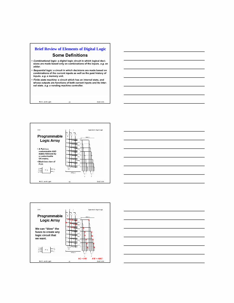
We Often Illustrate the PLA Like This
A B C
F0 F1
AC + A’B’ A’B’ + ABC’
ENCE 324144Wc11.arch.ppt
ENCE 324145Wc11.arch.ppt
ENCE 324146Wc11.arch.ppt
ENCE 324147Wc11.arch.ppt
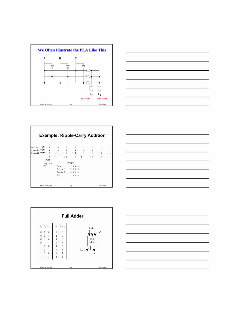
Carry-In A B Sum Carry-out
0 0 0 0 0
0 0 1 1 0
0 1 0 1 0
0 1 1 0 1
1 0 0 1 0
1 0 1 0 1
1 1 0 0 1
1 1 1 1 1
Sum = A’BC’ + AB’C’ + A’B’C + ABCCarry-out = ABC’ + A’BC + AB’C + ABC
ENCE 324148Wc11.arch.ppt
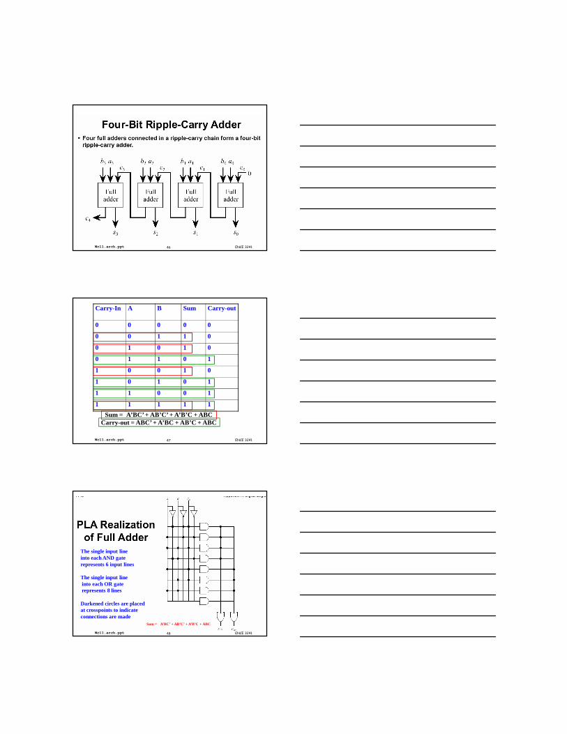
The single input lineinto each AND gaterepresents 6 input lines
The single input lineinto each OR gaterepresents 8 lines
Darkened circles are placedat crosspoints to indicate connections are made
Sum = A’BC’ + AB’C’ + A’B’C + ABC
ENCE 324149Wc11.arch.ppt
ENCE 324150Wc11.arch.ppt
ENCE 324151Wc11.arch.ppt
ENCE 324152Wc11.arch.ppt
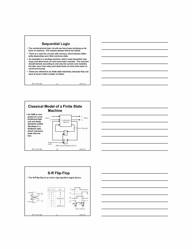
When A,B,C all changedfrom 0 to 1, there willBe a glitch.
ENCE 324155Wc11.arch.ppt
ENCE 324164Wc11.arch.ppt
Finite State Machine from Sequential Logic
ENCE 324165Wc11.arch.ppt
ENCE 324166Wc11.arch.ppt
ENCE 324167Wc11.arch.ppt
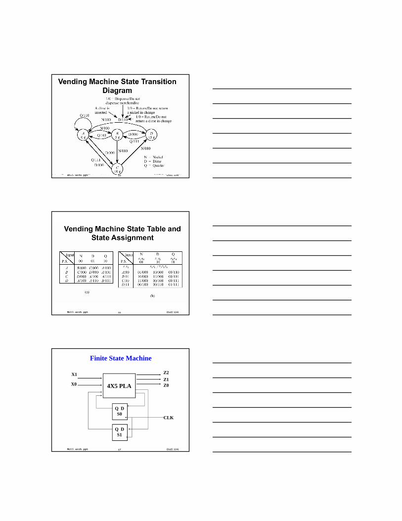
Finite State Machine
4X5 PLA
Q DS0
Q DS1
X1
X0
Z2
Z1Z0
CLK
ENCE 324168Wc11.arch.ppt
Truth Table for Vending Machine S1 S0 X1 X0 S1 S0 Z0 Z1 Z20 0 0 0 0 1 0 0 00 0 0 1 1 0 0 0 00 0 1 0 0 0 1 1 00 1 0 0 1 0 0 0 00 1 0 1 1 1 0 0 00 1 1 0 0 0 1 0 11 0 0 0 1 1 0 0 01 0 0 1 0 0 1 0 01 0 1 0 0 0 1 1 11 1 0 0 0 0 1 0 01 1 0 1 0 0 1 1 01 1 1 0 0 1 1 1 1
ENCE 324169Wc11.arch.ppt
Example
• Assume our vending machine takes only nickels and dimes.• The machine vends items for 15 cents.• What is the state transition diagram?
ENCE 324170Wc11.arch.ppt
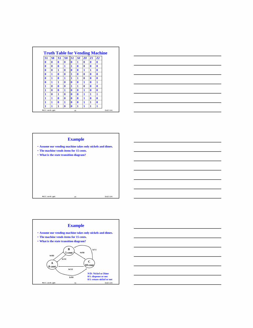
Example
• Assume our vending machine takes only nickels and dimes.• The machine vends items for 15 cents.• What is the state transition diagram?
A0 cent
B5 cent
C10 cent
N/00
N/00
N/10
D/00
D/10
D/11
N/D: Nickel or Dime0/1: dispense or not 0/1: return nickel or not
![Springer Pub. Co. Prototyping on the PC with Programmable ... · and Abbott 1994], the CLP (Configurable Logic Processor) VMEbus machine vision processor [Dunn 1995], the TERAMAC](https://static.fdocuments.net/doc/165x107/5fafa21435003956890f382a/springer-pub-co-prototyping-on-the-pc-with-programmable-and-abbott-1994.jpg)