CES226632 Challenges of Bridge Design and Detailing in Revit
22
CES226632 Challenges of Bridge Design and Detailing in Revit Jakub Bielski SOFiSTiK AG Dirk Münzner Boll und Partner GmbH & Co KG Description This class will cover the topic of bridge modelling, detailing, and analysis in Revit software. Designers can create a bridge using axis alignment parameters and assign a parameterized cross section. Substructure components, such as piers and abutments, are constructed as Revit families and placed in the project with reference to the axis. The user has direct access to the bridge’s and axis’s information. Modifications of the structure parameters are immediately implemented in the project. With the data already defined, an analytical model can be generated, and detailed analysis and design of the structure can be performed. Reinforcement and prestressing cables are modelled according to the bridge axis and adjusted in anchorage zones. Detailers can automatically create section views and place dimensions, as well as annotations Speaker(s) Jakub Bielski graduated as Structural Engineer at University of Technology in Cracow, Poland. During his studies and after, he took part in various competitions, workshops and conferences to enhance his qualifications, increase the knowledge and find innovative solutions for construction industries. Currently working as Product Manager in SOFiSTiK AG, he is responsible for creating new solutions for bridge design and reinforcement detailing in Autodesk environment. As managing partner, Dirk Muenzner is entrusted with the introduction and development of innovative planning and collaboration methods at Boll und Partner. His main areas of expertise include the integration of collaborative BIM planning methods at large scale infrastructure projects. As a speaker and author, he is an acknowledged and eligible expert in the field of BIM implementation in national and international projects. Learning Objectives • Learn how to create a geometric and analytical bridge model • Learn how to model and detail 3D rebars and prestressing for infrastructure projects • Learn how to manage the coordinates and position of a bridge in Revit • Learn how to create plans and documentation of the project
Transcript of CES226632 Challenges of Bridge Design and Detailing in Revit

CES226632
Challenges of Bridge Design and Detailing in Revit
Jakub Bielski SOFiSTiK AG Dirk Münzner Boll und Partner GmbH & Co KG
Description
This class will cover the topic of bridge modelling, detailing, and analysis in Revit software. Designers can create a bridge using axis alignment parameters and assign a parameterized cross section. Substructure components, such as piers and abutments, are constructed as Revit families and placed in the project with reference to the axis. The user has direct access to the bridge’s and axis’s information. Modifications of the structure parameters are immediately implemented in the project. With the data already defined, an analytical model can be generated, and detailed analysis and design of the structure can be performed. Reinforcement and prestressing cables are modelled according to the bridge axis and adjusted in anchorage zones. Detailers can automatically create section views and place dimensions, as well as annotations
Speaker(s)
Jakub Bielski graduated as Structural Engineer at University of Technology in Cracow, Poland. During his studies and after, he took part in various competitions, workshops and conferences to enhance his qualifications, increase the knowledge and find innovative solutions for construction industries. Currently working as Product Manager in SOFiSTiK AG, he is responsible for creating new solutions for bridge design and reinforcement detailing in Autodesk environment. As managing partner, Dirk Muenzner is entrusted with the introduction and development of innovative planning and collaboration methods at Boll und Partner. His main areas of expertise include the integration of collaborative BIM planning methods at large scale infrastructure projects. As a speaker and author, he is an acknowledged and eligible expert in the field of BIM implementation in national and international projects.
Learning Objectives
• Learn how to create a geometric and analytical bridge model
• Learn how to model and detail 3D rebars and prestressing for infrastructure projects
• Learn how to manage the coordinates and position of a bridge in Revit
• Learn how to create plans and documentation of the project

Introduction
BIM Technology is getting even more significant interest in the construction industry. Governments e.g. of England and Germany, are encouraging engineering companies to take a step towards technological development and are moving infrastructure projects to BIM technology. There are currently many tools, that are design in respect of BIM concept for buildings, but very few for infrastructure projects. As this branch is still under development, consultancy offices or larger companies are trying to close the gap with tools like Dynamo or other Workflows. This situation provides a field for development for other software providers, which can deliver 3rd Party plug-ins for software like Revit. SOFiSTiK is a German lead software provider for FEM analysis, 2D CAD construction and BIM plug-ins for rebars in Revit. Two new applications have been recently released: SOFiSTiK Analysis and Design for Revit and SOFiSTiK Bridge Modeler, which will be the main topic of this lecture. Aim of the presentation is to define the problems and limitations of the currents workflow and tools and suggest an alternative solution or temporary workarounds. Let’s take a look at what works, what doesn’t really work and what doesn’t work at all.. Following presentation was divided into three parts: 3D modelling, plan creation and example from praxis.
Challenges - Modelling
Coordinates
Problem 1. What is the difference between project, shared and internal coordinate system? What is
the purpose to have 3 of them?
2. How to manage the coordinate system for my bridge project?
3. How can I be sure, that my bridge is in the correct place?
Solution:
1. We suggest the following workflow to understand and manage the coordinates.
‘Project Base Point’ close to intern coordinate system > Revit Limitation of 9144m ‘Shared Coordinate system’ for collaboration purposes and to set a known point.

2. Make sure that survey point is correctly defined. Find a known point of your bridge e.g.
beginning of your superstructure. Place there Project Base Point
Define Axis according to this point – it will be easier to model your structure
3. The first thing is to define the Project Base and Survey Points properly. Then, we can
create an axis according to one of the coordinate systems. It can happen, that we don’t
know exact coordinates of the beginning of the axis, but one of the stations. We can
simply move an axis using Revit functionalities in our project. Axis coordinates will be
adjusted automatically.
Axis
Problem 1. How can I define my axis?
2. How can I control accuracy?
3. How connect more axis and make them dependent from each other?
Solution:
1. There are two basic types of road or bridge alignment definition.
Alignment Parameters - curve type (straight, arc, spiral etc..) with length and radius or
3D curve created by Connecting Points with XYZ coordinates. These tasks can be done
manually (I do not recommend) or automated by tools like dynamo or other Plug-ins.
Connection to external file formats (which basically contain the same data) can be very
useful. The workflow gets smoother transition from input data, saves some work and
decreases probability for potential errors.

2. Created Axis with Alignment Parameters is exact representation of given data. This
curve can be mathematically described with types of curves with additional attributes in
horizonal plane. Horizontal curvature takes an axis to the 3D area, where the geometry
cannot be described with previously given formulas. In order to create a superstructure
geometry of the bridge, the geometry need to be read again and recreated with a spline
driven by points. Because of the lack of the points’ orientation, the accuracy needs to be
controlled by the number of points along an axis. (picture of the spline through points
with the deviation)
3. We can define so called secondary axis that are using two sources of geometrical
definition. Geometry of the main axis and offset in horizontal and vertical direction.
Changes in the main axis will directly influence the secondary axis. Secondary axis can
be used for the definition of bridge components, cross section parametrisation or
Prestressing cable definition.
Superstructure:
Problem 1. How can I create a complex superstructure element?
2. How to define my cross section?
3. How can I define the variability of the superstructure?
4. How can I modify my bridge?

Solution:
1. Use 3D forming tools in Revit Family. Place a section on your axis and generate a form
with loft tool.
Of course, automate the process for complex structures!
2. You can define bridge cross section using Adaptive Generic Family. Using Revit
functionalities, you can sketch lines on one plane forming a closed loop. However, there
are some rules, that need to be followed. Only one external loop is allowed, all internal
loops are interpreted as openings, loops mustn’t intersect.
3. Define the Variables with accordance to your axis using tables or formulas and connect
them with Cross Section parameters.
4. Direct access to the information by ‘Edit’ tools

Substructure:
Problem 1. How can I define my substructure and parametrize it?
2. How can I be sure, that substructure component is in the right place?
Solution:
1. Simply, using Revit Families. This basic Revit modelling tool is perfect for modelling
geometry elements like substructures, abutments, piers etc. These objects vary in form
and dimensions. It is up to you, if you want to create more families with different
dimension or one with more parameters. Level of detail and additional parameters, like
materials estimated costs are also included and filled in according to your needs.
2. Substructure components are created at the placement and tightly connected to it. If
placement moves, the substructure will move accordingly. While placing and editing
substructure element, you can set additional offset or rotation parameters.
Bridge equipment
Problem 1. How to create the additional equipment of the bridge with proper alignment? Parapets,
railings etc..
Solution:
1. As these elements are defined according to the bridge (in most cases deck) geometry,
and cross slope, it makes more sense to define such elements with respect to these
conditions. You can create continuous or repeated elements along the chosen edge of
the bridge. These elements are responsive to the faces, that are creating chosen edge.

Prestressing in Revit
Problem 1. There is no prestressing objects in Revit. What can I do?
2. How can I define geometry of prestressing cables?
3. How to modify it?
Solution:
1. Be creative! SOFiSTiK concept for prestressing in Revit is using a FreeForm Rebar
object as prestressing cables and rebar couplers as anchorages. Prestressing cables
are also called ‘active reinforcement’! For detailing purposes, recognition between
prestressing cables and native reinforcement is made using SOFiSTiK_Tendon
parameter in Rebar Type properties.
2. At the moment you can create prestressing cables using the geometry of any 3D curve.
Bridge Modeler reads the geometry data of the curve. FreeForm Rebar object with
activated SOFiSTiK_Tendon Parameter is created at the place. New tool with more
intuitive and advanced input and dynamic update is being developed.
3. We can modify Tendon both globally and locally. In case of big changes, it’s better to
change the geometry of the curve and recreate tendon. If only local changes are
needed, you can open Prestressing cable in Tendon Editor and change the geometry of
the spline by moving the points.

Reinforcement
Problem 1. How can I create rebars in complex structures?
2. How can I annotate it?
Solution:
1. You can use Freeform rebars. These objects are under constant development and can
‘do more’ with each Revit release.
2. You can use SOFiSTiK Reinforcement Detailing. Wide range of tool for annotation and
rebar detailing will accelerate creation of Rebar Drawings

Challenges – Shop Drawings
Section Views
Problem 1. How can I define my cross section? My snap tool doesn’t work with complex curves
2. I don’t know where exactly my section view is. I cannot use dimensions anymore.
3. How can I create multiple section views? Copy or array tools don’t work for bridges.
Solution:
1. Bridge Modeler is using its own data structure. Access to this data is useful not only for
modelling purposes, but also for detailing. Using axis geometry, we can create a section
view perpendicular to the axis (or with the given rotation).
2. Cross sections are created according to the defined stationing. We know exactly where
our cross section is! Using the same data for multiple tools allows us to stay compatible
with created elements e.g. grid in the cross section.
3. Creating a single cross section along an axis many times can be time consuming
process. You can boost this process by creating multiple cross sections using well-
known Revit layout definition. ‘Layout > Rule > Spacing ‘
Of course we want to extract as much information from given and processed data as
possible. While creating section views, we can place a dimension, that are previously
defined in the bridge cross section family.

Longitudinal Unfolded View
Problem 1. How can I create unfolded view in Revit and annotate it?
Solution:
1. It is quite simple, you cannot. At least not now and not the one, that you are used to see.
Till now, Revit provides no unfolded view. We can find some workarounds like multiple
views arranged together, unfolded geometry with section or lines created using points of
profiles (Dynamo).
Bridge Modeler offers another solution. We can cut the geometry with vertical surface
defined by the axis or other curve. Intersection of the surface and cut element defines a
line which is being unfolded and sketched in the detail element. Additionally, we can
choose which elements (edges) should be projected on the surface as well. Created
detail elements are arranged together in the section and placed in respect to the proper
elevation.
This gives us an opportunity to annotate the section with dimensioning lines, elevation
points and slopes.

An outstanding example project
A bridge as a BIM model – 2nd Gauchachtalbrücke The German government has chosen several outstanding projects to be planned with the BIM- method as flagship projects – the tallest of those pilot- projects is the 2nd Gauchachtalbrücke in the very south of Germany. Its crosses a side valley of the Wutachschlucht, one of the most rugged landscapes in Middle Europe, also know as the “Grand Canyon of Swabia”. The 2nd Gauchachtalbrücke will help to cope with the rising traffic on the B31 highway, connecting the river Rhine valley and the Lake Constance area.

It’s BIM? BIM is a concept used in various differing ways and a diverse range of projects. The differentiation between a 3D model and BIM however is a frequently unspecified and thus often asked question.
BIM = 3D model? The Sofistik Bridge Modeler implicates an extraordinary simplification to the modelling process, as there is no further need to use additional programs like C3D or to intensively employ Dynamo tointegrate a bridge “into” a BIM-environment. But a BIM process is more than modelling – this will clarify with the help of the following topics.
BIM = 3D model with many details? Pushing the content of the model to a higher LOD- level and adding more features and details produces great visualizations but the result is still a 3D model.

BIM = 3D model with a pointcloud? A common issue regarding infrastructure projects (compared to high-rised buildings) is that a bridge or tunnel must always be planned into an existing terrain as well as other infrastructure, in addition environmental aspects have to be considered.. One of the first steps at the Gauchachtal Bridge was to take several large scale laserscans via Gyrocopter, drones, terrestrial and by car. The result could be loaded into Revit und was a great support while modelling retaining walls, logistics and the structure itself.

BIM is a method and not a model – it‘s defined in the Project Execution Plan
BIM = defining use- Cases The use- Cases and the moels required level of development of the model are defined within the BIM- Project Execution Plan (PEP), This has to be the essential basis before developing processes etc before starting to setup an model.

First step = survey and GIS In our case the first step was to create an initial model, representing the surface, existing road- and waterways, environmental issues and property lines.
The data was collected by the specialist Nebel& Partner by using a fully equipped gyrocopter and transformed into ReCap. Additional data was collected with the drones operated by Boll und Partner.
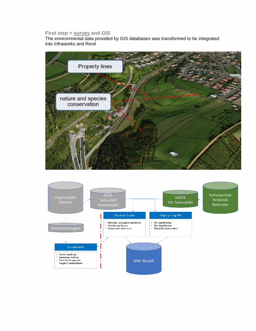
First step = survey and GIS The environmental data provided by GIS databases was transformed to be integrated into Infraworks and Revit

Second step = define Revit families and attributes The Sofistik bridge modeler is highly depending on the families used as placements or parts of the model. Setting up those families to meet all the requirements of the PEP is a very demanding job, as those parts are used for: - 3D- modelling - automatic generation of 2D plans - cost- and schedule planning - visualization - collision planning - etc.

Third step = bring it together Using the Sofistik Bridgemodeler enabled us to dynamically place piers, griders, parapets, railings and all the bits and parts needed to model a bridge.
Having invested a lot of time in step 2 in order to implement all the attributes and WBS into the families, the result is a BIM model – and not only a 3D model.
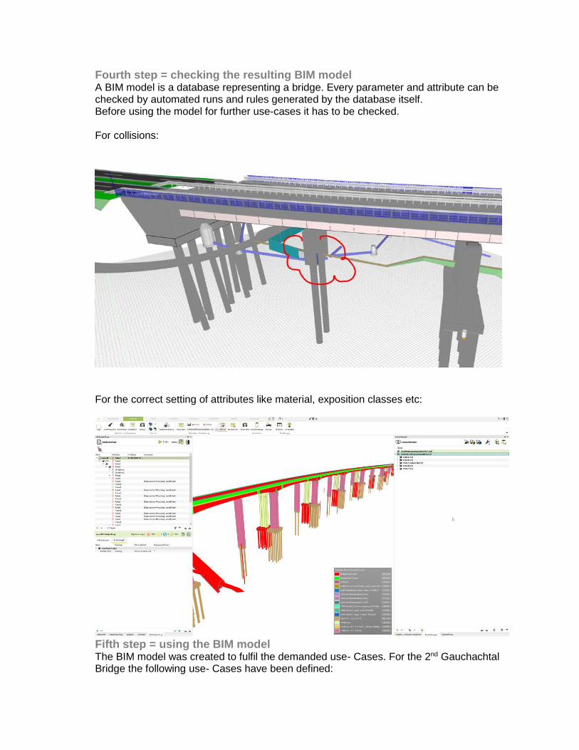
Fourth step = checking the resulting BIM model A BIM model is a database representing a bridge. Every parameter and attribute can be checked by automated runs and rules generated by the database itself. Before using the model for further use-cases it has to be checked. For collisions:
For the correct setting of attributes like material, exposition classes etc:
Fifth step = using the BIM model The BIM model was created to fulfil the demanded use- Cases. For the 2nd Gauchachtal Bridge the following use- Cases have been defined:

• Automatic plan generation
• Schedule planning
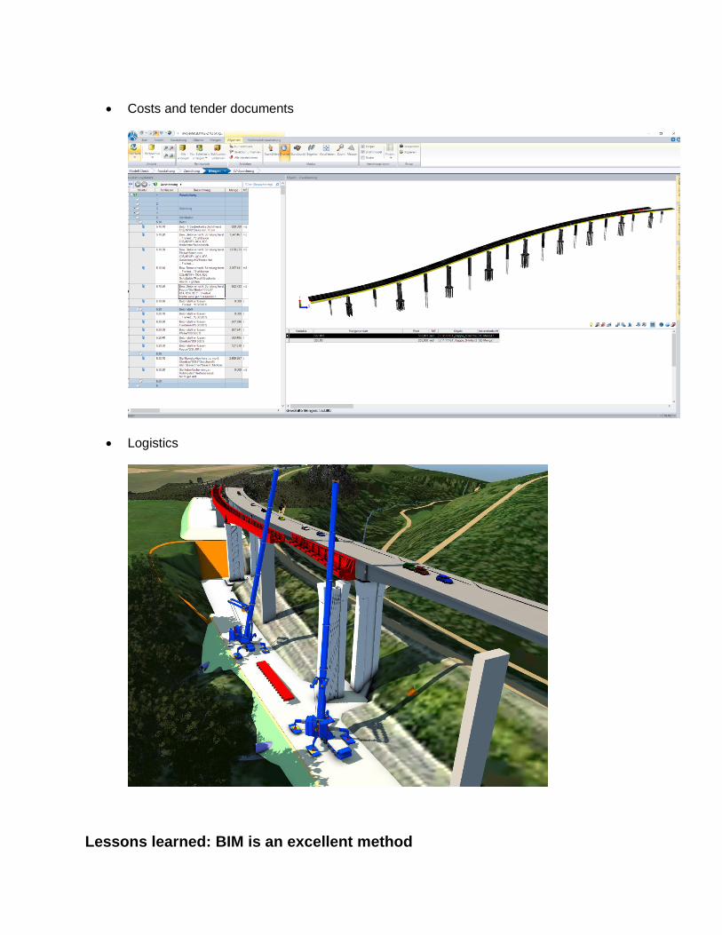
• Costs and tender documents
• Logistics
Lessons learned: BIM is an excellent method

Large scale and complex geometry
The pathfinder project showed the great potential for the use of BIM also in large scale projects with a super complex geometry. With the possibility to use the “Sofistik Bridge designer” for a lean workflow within one software and without the need for Dynamo programming experts we at Boll und Partner expect many more interesting projects in the near future with BIM.